

Page 1
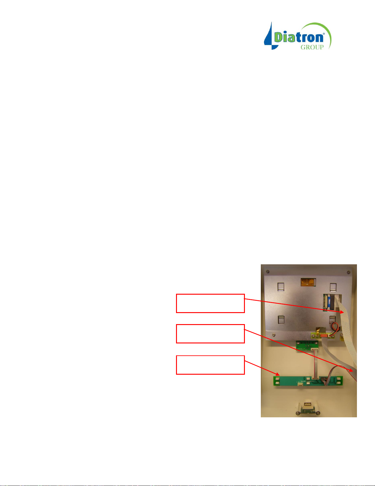
Abacus 380
Status LED Board
Monitor signal cable
BLTSST cable
Display frame installation
The list of tools you will need for the upgrade:
- 2.5 Allen screw driver
- Forceps or pliers, tweezers
- TX-10 Torx screw driver
1. Please shut down the system and disconnect it from the power source.
2. Remove the front cover from the instrument:
a. Remove the top-left cover.
b. Disconnect the flat BLTSST cable from the C_BLTSST connector of ACS Main board and
the monitor signal cable from C_LCD connector from the outer side of the ACS Main
board.
c. Remove the screws that fix the front cover. Two flat-head Torx screws on the sides, four
Allen screws on the bottom side of the instrument.
d. Remove the grounding cable from the front panel. (pull it off the connector)
3. Remove the display from the Front panel
a. Put the Front Panel on its front to access the display
1
Page 2
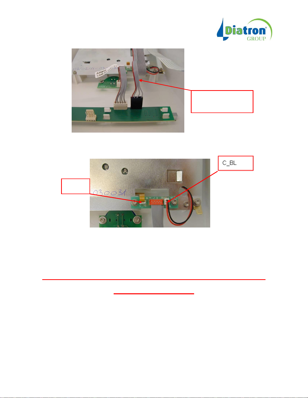
BLTSST cable – Start
button control section
C_TS
b. Disconnect the BLTS cable from the Status LED Board
c. Remove the Back Light cable (red/black) from C_BL connector
Note: The backlight cable might be tight. You may need to force a little bit to remove the backlight cable.
d. Remove the Touch screen flat cable from C_TS connector.
Do it very carefully, because touch screen flat cable is
Extremely fragile!!!
Use the forceps when you remove it.
2
Page 3
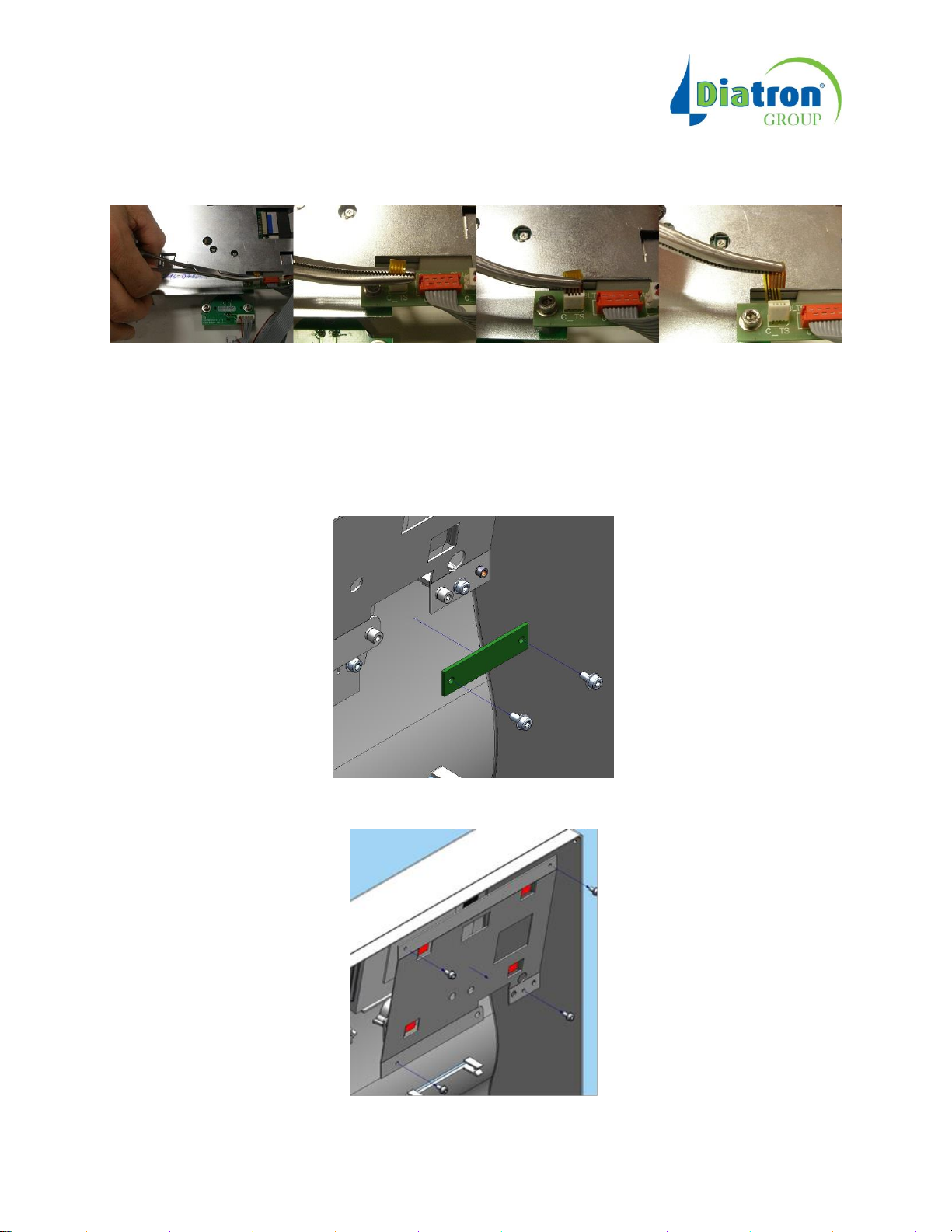
See pictures below:
1, 2, 3, 4,
1,-2, Hold the cable with the forceps at the connection.
3, Turn the forceps and it will pull the cable out from the connector.
4, Do it slowly till the cable is out. Remove forceps.
e. Remove the screws that held the BLTS board.
f. Remove the screws that held the Display holder panel and remove this holder panel with
the display.
3
Page 4
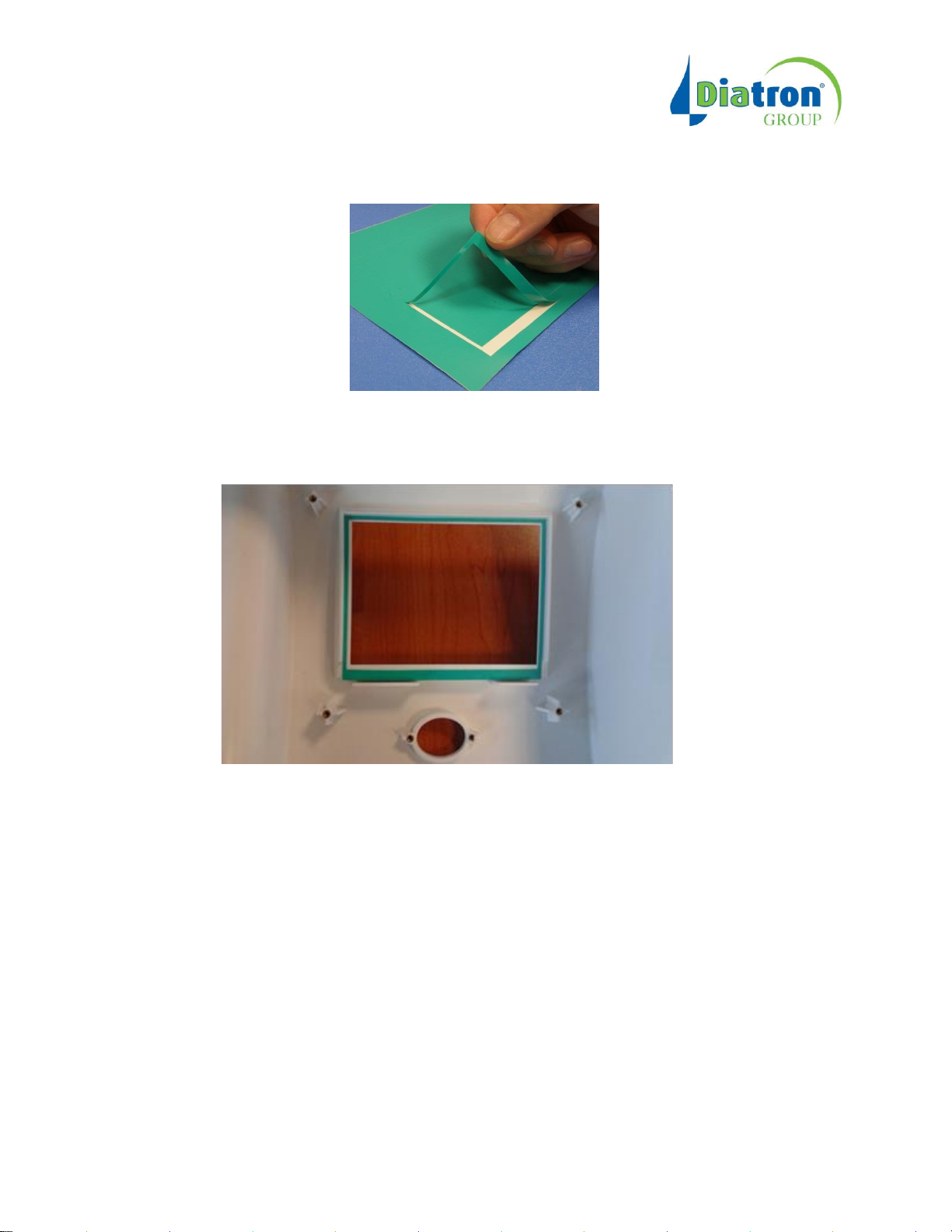
4. Install the extra frame to the Front panel
a. Take the frame from the precut adhesive film
b. Fix it into the back side of the Front Panel
5. Reinstall the display to the Front panel
a. Put back the original display to the Front cover if its touch cable was not damaged when
it was removed from connector C_TS (It is in paragraph 3.,d). If so replace the display
unit.
b. Install the metal Display holder panel. Fix it with its four screws.
c. Screw back the new BLTS board
d. Connect the touch cable and the back light cable to the BLTS
e. Connect the BLTS cable to the Status LED Board
6. Reassemble the front panel with the rest of the analyzer.
a. Connect the BLTSST cable and the white monitor signal cable to the ACS main board
4
Page 5

b. Connect the grounding cable to the front panel
7. Check the system operation
a. Switch the system on
b. Step in the Touchscreen calibration by pressing a neutral, unused area of the main
screen for a few second where there is no any button, and calibrate the screen.
The upgrade is done.
5
 Loading...