


2THOUSANDTWELVE
510Ic
Indoor Cycle
OWNER’S MANUAL

PURCHASER’S REFERENCE INFORMATION
PLEASE RECORD DETAILS ASSOCIATED WITH THE PURCHASE OF YOUR 510Ic BELOW. THIS INFORMATION WILL BE REQUIRED IN THE EVENT THE UNIT REQUIRES FUTURE SERVICE.
*ATTACH THE PURCHASE RECEIPT HERE:
Product Name: Diamondback 510Ic Indoor Cycle
Serial Number: E ___ ___ ___ ___ ___ ___ ___ ___ ___ ___
Date Purchased:
Dealer Name:
Dealer Address:
Dealer Contact Name:
Dealer Telephone Number: ( |
) |
|
|
|
|
SERIAL NUMBER
IIII III IIIII IIIIII
SAMPLEE0000000000
W RNING: REMOVAL
Serial Number Location
To Activate Warranty: Register the unit at www.diamondbackfitness.com OR complete the attached warranty card (see last page) and return it to Diamondback Fitness within 15 days of purchase.
Failure to comply may limit or void the Manufacturer’s warranty coverage.
Shipping Materials: Diamondback Fitness recommends that you retain the original packing materials (box and
packing items) for future shipping needs. |
Warranty: ____ Mailed ____ Online |
Date ________________ |
|
2

510Ic Owner’s Manual
SAVE THIS OPERATING INSTRUCTIONS MANUAL FOR YOUR REFERENCE.
510Ic
Computer Controlled Indoor Cycle
Diamondback Fitness
Release v.2 (7/2011)
1

TABLE OF CONTENTS
PURCHASER’S REFERENCE INFORMATION - Inside Front Cover
INTRODUCTION |
3 |
SAFETY INSTRUCTIONS & WARNINGS |
4 |
CARTON CONTENTS |
7 |
510Ic ASSEMBLY INSTRUCTIONS |
8 |
WORKOUT GUIDELINES |
13 |
WORKOUT QUALITY AND QUANTITY |
17 |
CONSOLE OVERVIEW & GENERAL NOTES |
18 |
CONSOLE KEYPAD FUNCTION |
20 |
CONSOLE OPERATION AND FEATURES |
21 |
PROGRAM CATEGORIES |
23 |
TROUBLESHOOTING |
29 |
MAINTENANCE |
30 |
WARRANTY INFORMATION |
31 |
WARRANTY REGISTRATION CARD |
35 |
2

510Ic Owner’s Manual
INTRODUCTION
Congratulations on the purchase of your new 510Ic Computer-Controlled Indoor Cycle from Diamondback Fitness. You have made a smart choice and are about to enjoy one of the most effective and technically-advanced methods of cardio-vascular exercise available today.
Founded in 1991 as an off-shoot of the legendary bicycle division, Diamondback Fitness was in many ways a complimentary addition to the Diamondback brand. One might even say this extension grew as a natural evolution from classic outdoor bicycle usage toward indoor-based cycling and cross training. It turns out many fitness enthusiasts were searching for ways to maintain conditioning during times of inclement weather or were simply looking for new and different crosstraining options.
This trend still continues today, twenty years later, as the strong Diamondback brand resonates with both the boomers who grew up with the bicycles, as well as the younger generations riding them today.
Diamondback Fitness continues to build upon this legendary brand identity by offering the cardio enthusiast a full line of upright bikes, recumbents, indoor cycles, and elliptical trainers that offer great value, high quality and intuitive & visually-pleasing design. Let’s just say, we are already planning our next twenty years.
Diamondback Fitness
6004 South 190th Street Suite 101 Kent WA 98032 Ph. 1.800.776.7642 Fax: 1.800.776.2073
For more information or questions regarding your equipment, please visit our website at www.diamondbackfitness.com
3

SAFETY INSTRUCTIONS & WARNINGS
Every piece of Diamondback Fitness equipment is built for maximum safety and meets or exceeds all applicable domes c and interna onal standards. However, certain precau ons must be taken when opera ng any exercise equipment.
NOTE: Please read the en re owner’s manual before opera ng the 510Ic.
CAUTION - FOR SAFE OPERATION
•Keep your hands and feet away from all moving parts and pinch points.
•If you have a history of heart disease, high blood pressure, diabetes, chronic respiratory diseases, elevated cholesterol, or if you smoke cigare es or experience any other chronic diseases or physical complaints, consult with a physician before beginning any exercise program.
•If overweight, or above the age of 35, consult with your physician before beginning any exercise program.
•Pregnant women should consult with their physician before beginning an exercise program.
•If you experience dizziness, nausea, chest pains or other abnormal symptoms during exercise, stop the exercise session immediately and consult your physician.
•Consume water before, during and a er each exercise session.
4

510Ic Owner’s Manual
SAFETY INSTRUCTIONS & WARNINGS
WARNINGS - TO REDUCE RISK OF INJURY TO YOURSELF OR OTHERS
•To ensure proper func oning of your unit, do not install a achments or accessories not provided or recommended by Diamondback Fitness.
•Always wear proper clothing and shoes when exercising.
•User weight is not to exceed 300 pounds (147.4 Kg) for the 510Ic.
•Keep children away from the unit. Hands and feet may become entangled with the moving parts and could result in serious injury.
•Place the unit in an area that will meet minimum clearance requirements:
-front & sides = 24 inches
-rear = 12 inches.
•The unit is intended for indoor use only.
•Place the unit on a solid, level surface. Always adjust the leveling feet before using to ensure stability.
•Ensure all adjustment knobs and levers are fastened securely before using the unit and a er making an adjustment.
•Use the handlebars when stepping on and o the unit.
•The unit is heavy. Do not a empt to move alone.
•Never operate the unit if it is damaged or broken. Contact your local authorized Diamondback Fitness Dealer for service.
•Always unplug the unit from the power source before moving or servicing.
•Do not remove the covers or other components. Only Authorized Diamondback Fitness Dealers or Authorized Technicians should perform service on the unit.
5
SAFETY INSTRUCTIONS & WARNINGS
Assembly of Technical Items
Assembly of all Diamondback Fitness products should be performed by a Diamondback Fitness Dealer or Authorized Technician. A significant amount of technical knowledge is required for the safe and complete assembly of the unit. Many retailers will o er delivery and assembly as part of the sales agreement. If this unit was sold unassembled (in the carton) and you do not feel you can perform the assembly successfully, please call the dealer for service. Service calls for improper assembly are not covered by the Warranty Policy and any associated charges will be the responsibility of the owner. Assembly may include adjustment and alignment of side cases and a achment brackets as needed for proper func on.
+ )ODW :DVKHU |
|
W |
|
|
|
|
+$OOHQ %ROW 0 3 PP |
+ )ODW :DVKHU |
|
W |
|
|
|
|
+ 6FUHZV 0 PP |
|
|
|
%R[ 6SDQQHU |
|
|
|
$OOHQ .H\ |
6FUHZGULYHU |
|
|
$OOHQ .H\ |
|
|
|
|
|
|
|
6 |

510Ic Owner’s Manual
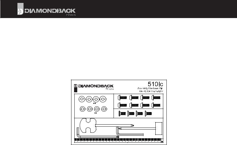
CARTON CONTENTS
Parts List
Item |
Description |
Quantity |
510ICġ |
A |
Console |
1 |
A-1 |
Console Fixing Screw |
4 |
B |
Handlebar Mast Assembly |
1 |
B-1 |
Handlebar Assembly Endcap |
1 |
B-4 |
Handlebar Assembly Endcap Screw |
1 |
B-5 |
Handlebars |
1 |
B-11 |
Heart Rate Console Wire |
1 |
B-13 |
Wire Harness - Upper |
1 |
C |
Rear Stabilizer Assembly |
1 |
D |
Front Stabilizer Assembly |
1 |
D-1 |
Leveling Foot Assembly |
4 |
D-2 |
Leveling Foot Lock Nut |
4 |
F-16 |
Power Input Jack |
1 |
F (L & R) |
Pedal, Clip & Strap Assembly (pair) |
1 |
G |
Main Frame |
1 |
G-1 |
Water Bottle Cage Assembly |
1 |
G-2 |
Water Bottle |
1 |
G-6 |
Stem / Seat Post Adjustment Knob |
1 |
G-9 |
Wire Harness - Lower |
1 |
G-13 |
Water Bottle Cage fixing screws |
1 |
H-1 |
Stabilizer Assembly Fixing Screw |
8 |
H-2 |
Stabilizer Assembly Curved Washer |
4 |
H-3 |
Stabilizer Assembly Flat Washer |
4 |
H-4 |
Handlebar Assembly Positioning Screw 4 |
|
K |
Assembly Hardware / Tool Kit |
1 |
L |
Saddle |
1 |
L-5 |
Fore-Aft Adjustment Lever |
1 |
M-1 |
Emergency Stop Knob |
1 |
N |
Power Supply/Adaptor |
1 |
7

ASSEMBLY INSTRUCTIONS
•Unpack the 510Ic from the carton. Please recycle.
•Verify the carton contains all parts from the list.
•Using the 6mm allen wrench, remove the blocking (the short
sec on of tubing installed at the factory to prevent damage to the front frame during shipping) by removing the two fixing screws shown in Figure 1 above.
•Discard this piece.
•Align the front stabilizer (D) with the receiver located in the front of the frame, and loosely install four (4) H-1 bolts, two (2) curved
washers (H-2) and two (2) flat washers (H-3), making sure that the correct shape of washers are installed on their corresponding surface profile; i.e. flat washer on the flat surface, etc. When all bolts have been inserted, ghten for final installa on with the 6mm allen wrench.
• Repeat this process for the rear stabilizer assembly (C).
8
510Ic Owner’s Manual
ASSEMBLY INSTRUCTIONS
• Install the saddle (L) onto the seat post and ghten with the included wrench.
• Install the pedals (F-L & F-R) into the crank arms. Threading the le pedal (marked with an “L”) by hand into the le crank with a counter-clockwise rota on. Do not cross-thread the cranks/pedals. The pedal must be ght and installed completely to prevent future damage to the cranks.
•Repeat the pedal installa on steps for the right side, no ng that the pedal will thread into the right crank with a clockwise rota on.
•Install the handlebars by sliding the bracket up under the handlebar mast (B) Feed the Heart Rate Console Wire (B-11) through the opening under the mast and pull it up and out with the wire harness.
•Posi on the Handlebars (B-5) in 1 of 3 possible posi ons
depending on user preference and install the 4 (H-4) Handlebar Assembly Posi oning Screws into place and ghten with
the 6mm allen wrench securing the Handlebars (B-5) to the Handlebar Mast (B).
• Make sure not to pinch the the Heart Rate Console Wire (B-11).
9
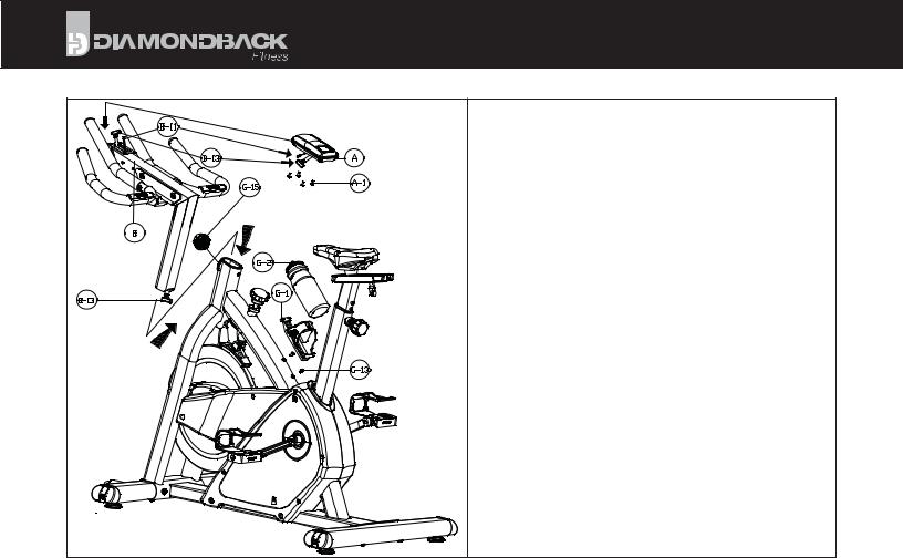
ASSEMBLY INSTRUCTIONS
•Insert the handlebar/stem assembly into the receiver on the main frame, paying care not to pinch the wire harness connector (B-13).
•Loosen the stem height adjuster knob (G-15) with two or three counter-clockwise rota ons. Adjust the stem/handlebar assembly to the lowest posi on by pulling outward on the knob to disengage the pop-pin. If the stem assembly does not drop, loosen the knob further and pull outward on the knob again. Repeat these steps again if necessary.
•Remove the four console fixing screws (A-1) from the back of the Console (A) and set them aside.
•Plug the upper wire harness connector (B-13) and the Heart Rate Console Wire (B-11) into the matching connectors on the back of the Console (A). Make sure both connec ons are firmly connected and click into posi on.
•Posi on the console above the moun ng plate located on the Handlebar Mast (B). Be careful feeding excess wires into the opening on the Handlebar Mast (B) while posi oning the console.
•Reinstall the four (4) fixing screws (A-1) through the underside of the plate and into the console. Tighten the four screws only a er all four have been started by hand.
•Install the Water Bo le Cage (G-1) using the 2 Water Bo le Cage Assembly Screws (G-13). Insert Water Bo le (G-2) into Water Bo le Cage (G-1).
10
 Loading...