


Purchaser's Reference Information
IT IS IMPERATIVE THAT YOU FILL IN THE FOLLOWING INFORMATION AND REFER TO IT SHOULD THE NEED FOR SERVICE ARISE.
Product Name: |
Diamondback 500Ub Upright or 500Sr Recumbent |
Serial Number: |
E __ __ __ __ __ __ __ __ __ __ |
To Activate Warranty:
1.REGISTER YOUR WARRANTY AT www.diamondbackÞtness.com OR
2.COMPLETELY FILL OUT THE ATTACHED WARRANTY CARD (SEE BACK COVER) AND RETURN TO DIAMONDBACK WITHIN 15 DAYS OF THE DATE OF PURCHASE. FAILURE TO COMPLY WITH THE WARRANTY ACTIVATION PROCEDURE MAY VOID THE MANUFACTURER'S WARRANTY.
Serial Number Location
Serial Number Sticker
Serial Number Sticker
Dealer Name: _________________________________________________________________________________________
Dealer Address: _______________________________________________________________________________________
Dealer Telephone Number: ( _____) ____________________________________________________________________
Dealer Contact Name: _________________________________________________________________________________
Date Purchased: ______________________________________________________________________________________
Shipping Materials:
Diamondback recommends that you retain the original packing materials (box and packing items) for future shipping needs.
2
500Ub.Sr OM R1.indd 2-3
Table of Contents |
|
Purchaser’s Reference Information .......................................................................................................................... |
2 |
Introduction ................................................................................................................................................................... |
4 |
Safety Instructions and Warnings .............................................................................................................................. |
5 |
500Ub Upright Assembly Drawing ............................................................................................................................ |
6 |
500Ub Upright Assembly Instructions ...................................................................................................................... |
7 |
500Sr Recumbent Assembly Drawing .................................................................................................................... |
9 |
500Sr Recumbent Assembly Instructions............................................................................................................. |
10 |
Workout Guidelines ................................................................................................................................................... |
12 |
Maximum Heart Rate & Training Zone.......................................................................................................... |
13 |
Quantity & Quality ............................................................................................................................................. |
13 |
Pulse Hand Grips ....................................................................................................................................................... |
15 |
Console |
|
Glossary of Terms ............................................................................................................................................ |
15 |
Default Values ................................................................................................................................................... |
15 |
Operating Tips ................................................................................................................................................... |
15 |
Console Layout ................................................................................................................................................ |
17 |
Displays .............................................................................................................................................................. |
18 |
Function Keys ................................................................................................................................................... |
19 |
Features ............................................................................................................................................................ |
20 |
Workout Programs |
|
Warm Up ............................................................................................................................................................ |
21 |
Cool Down ......................................................................................................................................................... |
21 |
Workout Summary .......................................................................................................................................... |
22 |
Quick Start ........................................................................................................................................................ |
23 |
Classic Programs |
|
Manual ..................................................................................................................................................... |
24 |
Random .................................................................................................................................................. |
25 |
Interval ...................................................................................................................................................... |
27 |
Hill Climb .................................................................................................................................................. |
28 |
Custom Trainer ....................................................................................................................................... |
30 |
HR Interactive Program |
|
Target HR ................................................................................................................................................ |
32 |
Maintenance .............................................................................................................................................................. |
34 |
Domestic Warranty Information ............................................................................................................................... |
35 |
Warranty Card ............................................................................................................................................................ |
39 |
3
6/11/2008 9:54:00 AM

Introduction
Congratulations on the purchase of your new cardio equipment from Diamondback. You have made a smart choice. You are about to experience one of the most effective and technically advanced methods of cardiovascular exercise available today.
Diamondback Fitness was founded as a brand extension of the legendary 30-year Diamondback bicycle division. The evolution of bicycles to home gyms for cross-training purposes and to stay fi t in inclement weather was a natural. Diamondback Fitness, known for delivering feature-packed, high-value equipment, has grown to a full line of cardio equipment including treadmills, ellipticals and stepper, as well as bikes, including innovative step-thru recumbents.
You can count on your Diamondback equipment to provide years of pleasure and improvement in your fi tness level. The solid construction and techno-savvy electronics are guaranteed to provide you with the ultimate workout experience.
For more information or questions regarding your equipment, please go to our website at www.diamondbackfi tness.com. Or contact us:
Diamondback Fitness c/o Raleigh America, Inc.
6004 S. 190th Street, Suite 101 Kent, WA 98032
Ph: 800.776.7642
Safety Instructions and Warnings
The 500 model units are built for optimum safety and are designed to meet or exceed all domestic and international standards. However, certain precautions need to be followed when operating any exercise equipment. BE SURE TO READ THE ENTIRE OWNERÕS MANUAL BEFORE OPERATING
YOUR 500 MODEL UNIT.
CAUTION Ð FOR SAFE OPERATION
1.Before beginning any exercise program on the 500 model unit it is important to consult with your physician if you have any of the following: History of heart disease, high blood pressure, diabetes, chronic respiratory diseases, elevated cholesterol, if you smoke cigarettes, experience any other chronic diseases, or physical complaints.
2.If over the age of 35 or overweight, consult with your physician before beginning any exercise program.
3.Pregnant women should consult with their physician before beginning an exercise program.
4.If you experience dizziness, nausea, chest pains or other abnormal symptoms during exercise, stop the exercise session immediately. Consult your physician before continuing your exercise.
5.Drink fl uids if you exercise for twenty or more minutes on any 500 model unit.
WARNING Ð TO REDUCE RISK OF INJURY TO YOURSELF OR OTHERS
1.To ensure proper functioning of your 500 model unit, do not install attachments or accessories not provided or recommended by Diamondback.
2.Always wear proper clothing and shoes when exercising on any 500 model unit.
3.User weight is not to exceed 275 pounds / 125 kilograms.
4.Keep children away from 500 model unit. Hands and feet may get caught in the pedals or other moving parts which could result in serious injury.
5.Place the 500 model unit in an area that will meet minimum clearance requirements: Front, Back & sides: 2 feet/60cm
6.Keep 500 model units away from walls to allow proper ventilation. Air should be able to circulate freely around the units. Keep all air openings free of dirt and dust. Never insert anything into openings.
7.The 500 model units are intended for indoor use in home environment. They are not intended for outdoor use.
8.Place your 500 model unit on a solid, level surface when in use.
9.Make sure all knobs for adjustments are fastened securely before getting on the unit and after making an adjustment (i.e. Seat post, saddle, seat assembly and handlebars).
10.Use the handlebars when getting on and off your 500 model unit.
11.Never operate the unit if it is damaged or broken. Contact your local authorized Diamondback Fitness dealer for service. Make sure all components are fastened securely (i.e. Seat post, saddle, seat assembly handlebars, and pedals) at all times.
4 |
5 |
||
500Ub.Sr OM R1.indd 4-5 |
|
|
6/11/2008 9:54:17 AM |
|
|
||
|
|
||
|
|
|
|

|
|
|
|
|
|
|
|
|
|
|
|
|
|
|
|
|
|
|
|
|
|
|
|
|
|
|
|
|
|
|
|
|
|
|
|
|
|
|
|
|
|
|
|
|
|
|
|
|
|
|
|
|
|
|
|
|
|
|
|
|
|
|
|
|
|
|
|
|
|
|
|
|
|
|
|
|
|
|
|
|
|
|
|
|
|
|
|
|
|
|
|
|
|
|
|
|
|
|
|
|
|
|
|
|
|
|
|
|
|
|
|
|
|
|
|
|
|
|
|
|
|
|
|
|
|
|
|
|
|
|
|
|
|
|
|
|
|
|
|
|
|
|
|
|
|
|
|
|
|
|
|
|
|
|
|
|
|
|
|
|
|
|
|
|
|
|
|
|
|
|
|
|
|
|
|
|
|
|
|
|
|
|
|
|
|
|
|
500Ub Upright Assembly Drawing |
|
500Ub Upright Assembly Instructions |
|||||||||||||||||||
Step 1: Stabilizer Bars Assembly
1. Place rear stabilizer bar under rear main frame body and align screw holes.
2. Insert two M8 x 75mm bolts into the stabilizer bar all the way through and into the holes on the frame
3. Secure rear stabilizer bar using an M8 nut and a curved washer on each bolt.
4. Repeat steps 1 – 3 to attach front stabilizer bar.
Step 2: Pedal Assembly
1. Use a 15mm open-end wrench to fi rmly affi x the pedals to the cranks.
2. The left and right pedals are different and are denoted as right or left (R or L) on the top & bottom of each pedal.
NOTE: Left pedal threads counterclockwise.
3. Retighten cranks after approximately 10 hours of use.
Step 3: Seat Post and Saddle assembly
1. Loosen the seat pin by turning it counter-clockwise 1-2 turns. Install seat post by sliding it into seat post receptor, pulling the seat pin out until a suitable hole is found.
2. Assemble saddle onto seat post.
3. Tighten the affi xing nut and washer using a 17mm open-end wrench.
SADDLE ANGLE ADJUSTMENT HINT: Hold the rear of saddle in the optimum comfort position and tighten the nut at the same time
Step 4: Console Mast Assembly
1. Remove console mast plastic cover from the unit's body by un-snap-
ping it.
2. Install console mast plastic cover onto console mast.
3. Connect the main wire harness in the main frame to the main wire har-
ness in the bottom of the console mast, taking care to install correctly.
(See plug alignment marks)
4. Install the console mast by sliding it into the console mast receptor
while gently pulling the wiring harness. This will keep the slack out of
the harness so the wires will not get pinched and short out. Insert and tighten three M8 x 16mm bolts, one fl at washer on each side and a curve washer on the front using a 6mm Allen wrench. Be sure not to pinch wire harness while tightening these three screws and make sure that the two top holes are light up with the holes on the receptor.
5. Snap console mast plast cover into top of sidecase.
6. Insert and tighten two M8 x 16mm bolts and fl at washers onto the two holes above the console mast
6 |
7 |
||
500Ub.Sr OM R1.indd 6-7 |
|
|
6/11/2008 9:54:18 AM |
|
|
||
|
|
||
|
|
|
|
500Ub Upright Assembly Instructions (Continued)
cover using a 6mm Allen wrench.
7.Place the bottle holder on the console mast. Insert and tighten the two M5 x 12mm screws using a Phillips screwdriver.
8.Snap the water bottle into the bottle holder.
Step 5: Handlebar Assembly
1. Insert the hand pulse harness through the opening on the left side of the console mast and out the top of the console mast.
2. Set the handlebar in place and secure it using a clamp, an M7 x P1.0 x 30mm bolt with a spring washer and fl at washer on top hole of the clamp and a T-shape Knob with a bushing, a fl at washer and spring washer on bottom hole of the clamp. As the bolt and T-shape knob are tightened leave the same gap on top and bottom.
3.Install the handlebar top and bottom covers by attaching them to each other from the opening in the bottom of the bottom cover using two M3 x 14mm Screws and one M5 x 25mm on each side of each cover.
Step 6: Console Assembly
1. Insert the ends of the main wiring harness and hand pulse wiring harness, trough the opening of the rear console cover.
2. Connect both plugs, from the main wiring harness and hand pulse wiring harness, to the plug receptors on the backside of the console taking care to install correctly (see plug alignment marks).
WIRING HARNESS INSTALLATION HINT: Any excess wiring must be carefully inserted (“stored”) back into the console mast before installing the console onto the console mounting plate.
3.Attach the console to the console mounting plate with the four M5 x 10mm screws on the top and bottom holes of the mounting plate using a Phillips screwdriver.
4.Attach the rear console coverl to the back of the console using four M5 x 10mm screws using a Phillips screwdriver.
5.Attach the right console plastic mount hood to console mast using one M5 x 14mm bolt and Phillips screwdriver. The cover should sit above the plastic handlebar covers and below the mounting brackter for the console
6.Attach the left console plastic mount hood to console mast using one M5 x 14mm bolt then to the right cover using three M3 x 14mm screws and a Phillips screwdriver.
Step 7: Transformer Assembly
1.Plug transformer into plug receptor located on the rear of the unit
2.Plug the transformer into power outlet.
NOTE: Be sure to use the right transformer for your power outlet, 110V or 220V.
8
500Ub.Sr OM R1.indd 8-9
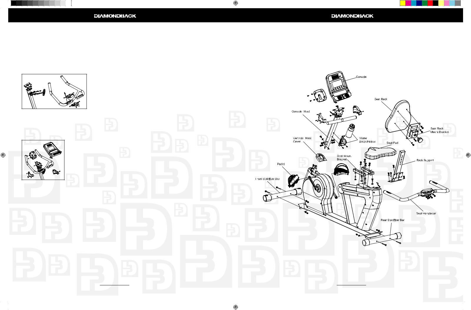
500Sr Recumbent Assembly Drawing
9
6/11/2008 9:54:21 AM
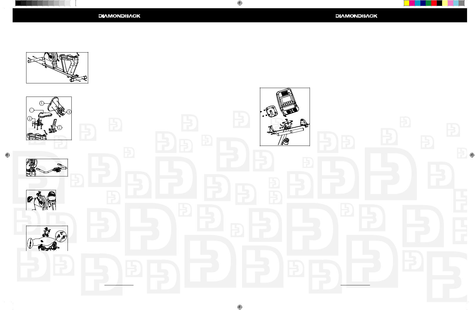
500Sr Recumbent Assembly Instructions
Step 1: Stabilizer Bars
1. Place rear stabilizer bar under rear main frame body and align screw holes.
2. Insert two M8 x 75mm bolts into the stabilizer bar all the way through and into the holes on the frame
3. Secure the stabilizer bar using an M8 nut and a curved washer on each bolt.
4. Repeat steps 1 – 3 to attach front stabilizer.
Step 2: Seat Assembly
1. Install seat mount bracket to seat slide on the seat track using four M8 x 16mm bolts and four washers.
2. Install seat support to seat slide on the seat track using four M8 x 16mm bolts and four washers.
3. Loosen the seat back locking pin by turning it counter-clockwise 1-2 turns. Install the seat back mount bracket by sliding it onto the back support tube, pulling the seat pin out until a suitable hole is found.
4. Install the seat pad on seat mount bracket using four M8 x 45mm bolts and four washers
5. Install the seat back pad on seat back mount bracket using four M8 x 16mm bolts and washers.
Step 3: Rear Handle Bar
1. Install rear handle bar to the bracket on the rear of the back support tube using four M8 x 16mm and four fl at washers
2. Plug in the HR pulse harness coming out of the plastic body to the receptor on the back of the handle bar.
Step 4: Pedals Assembly
1. Use a 15mm open-end wrench to fi rmly affi x the pedals to the cranks.


 2. The left and right pedals are different and are denoted as right or left (R or L) on the
top & bottom of each pedal.


 NOTE: Left pedal threads counterclockwise.
 3. Retighten cranks after approximately 10 hours of use.
Step 5: Console Mast & Water Bottle Assembly
1. Remove console mast plastic cover from the unit's body by un-snapping it. 2. Slide console mast cover onto bottom of console mast
3. Connect both the main wire harness and the hand pulse harness in the main frame to the two wire harnesses in the bottom of the console mast, taking care to install correctly. (See plug alignment marks)
 4. Install the console mast by sliding it into the console mast receptor while gently pulling the wiring harness. This will keep the slack out of the harness so the wires will not get pinched and short out. Insert and tighten three M8 x 16mm bolts, one fl at washer on each side and a curve washer on the front using a 6mm Allen wrench. Be sure not to pinch wire harness while tightening these
10
500Ub.Sr OM R1.indd 10-11
500Sr Recumbent Assembly Instructions (Continued)
three screws and make sure that the two top holes are light up with the holes on the receptor.
4.Snap console mast cover into top of sidecase.
5.Insert and tighten two M8 x 16mm bolts and fl at washers onto the two holes above the console mast cover using a 6mm Allen wrench.
6.Place the bottle holder on the console mast. Insert and tighten two M5 x 15mm screws using a Phillips screwdriver.
7.Snap the water bottle into the bottle holder.
Step 6: Console Assembly
1. Insert the ends of the main wiring harness and hand pulse wiring harness, trough the opening of the rear console cover.
2. Connect both plugs, from the main wiring harness and hand pulse wiring harness, to the plug receptors on the backside of the console taking care to install correctly (see plug alignment marks).
WIRING HARNESS INSTALLATION HINT: Any excess wiring must be carefully inserted (“stored”) back into the console mast before installing the console onto the console mounting plate.
3. Attach the console to the console mounting plate with the four M5 x 10mm screws on the top and bottom holes of the mounting plate using a Phillips screwdriver.
4. Attach the rear console cover to the back of the console using four M5 x 10mm screws using a Phillips screwdriver.
5.Attach the right console plastic mount hood to console mast using one M5 x 14mm bolt and Phillips screwdriver. The cover should sit above the plastic handlebar cover and below the mounting bracket for the console.
6.Attach the left console plastic mount hood to console mast using one M5 x 14mm bolt then to the right cover using three M3 x 14mm screws and a Phillips screwdriver.
Step 7: Transformer Assembly
1.Plug transformer into plug receptor located on the front of the unit.
2.Plug the transformer into power outlet.
NOTE: Be sure to use the right transformer for your power outlet, 110V or 220V.
11
6/11/2008 9:54:24 AM
Workout Guidelines
Good health is an exercise in common sense
The Surgeon General released a study in 2001, The Surgeon General’s Call To Action To Prevent and Decrease Overweight and Obesity. It indicates that 61% of American adults are either overweight or obese. The study states that overweight increases the risk of health problems, such as heart disease, certain type of cancer, type 2 diabetes, etc. It further points out that overweight needs to be regarded primarily as a Health rather than as an Appearance issue.
The Surgeon General’s Healthy weight advice for consumers is:
1.Aim for a healthy weight: Find your Body Mass Index (BMI) on the chart below.
2.Be active: Keep physically active to balance the calories you consume.
3.Eat well: Select sensible portion sizes.
BMI = (weight (lb.)/ height² (in)) x 703
Weight in Pounds
120 130 140 150 160 170 180 190 200 210 220 230 240 250
|
4’6 |
29 |
31 |
34 |
36 |
39 |
|
41 |
43 |
46 |
48 |
51 |
53 |
56 |
58 |
60 |
|
4’8 |
27 |
29 |
31 |
34 |
36 |
|
38 |
40 |
43 |
45 |
47 |
49 |
52 |
54 |
56 |
|
4’10 |
25 |
27 |
29 |
31 |
34 |
|
36 |
38 |
40 |
42 |
44 |
46 |
48 |
50 |
52 |
|
5’0 |
23 |
25 |
27 |
29 |
31 |
|
33 |
35 |
37 |
39 |
41 |
43 |
45 |
47 |
49 |
|
5’2 |
22 |
24 |
26 |
27 |
29 |
|
31 |
33 |
35 |
37 |
38 |
40 |
42 |
44 |
46 |
Inches |
5’4 |
21 |
22 |
24 |
26 |
28 |
|
29 |
31 |
33 |
34 |
36 |
38 |
40 |
41 |
43 |
5’8 |
18 |
20 |
21 |
23 |
24 |
|
26 |
27 |
29 |
30 |
32 |
34 |
35 |
37 |
38 |
|
|
5’6 |
19 |
21 |
23 |
24 |
26 |
|
27 |
29 |
31 |
32 |
34 |
36 |
37 |
39 |
40 |
|
|
|
|
|
|
|
|
|
|
|
|
|
|
|
|
|
and |
5’10 |
17 |
19 |
20 |
22 |
23 |
|
24 |
26 |
27 |
29 |
30 |
32 |
33 |
35 |
36 |
6’0 |
16 |
18 |
19 |
20 |
22 |
|
23 |
24 |
26 |
27 |
28 |
30 |
31 |
33 |
34 |
|
Feet |
|
|||||||||||||||
6’2 |
15 |
17 |
18 |
19 |
21 |
|
22 |
23 |
24 |
26 |
27 |
28 |
30 |
31 |
32 |
|
in |
6’4 |
15 |
16 |
17 |
18 |
20 |
|
21 |
22 |
23 |
24 |
26 |
27 |
28 |
29 |
30 |
Height |
6’8 |
13 |
14 |
15 |
17 |
18 |
|
19 |
20 |
21 |
22 |
23 |
24 |
25 |
26 |
28 |
|
6’6 |
14 |
15 |
16 |
17 |
19 |
|
20 |
21 |
22 |
23 |
24 |
25 |
27 |
28 |
29 |
|
|
|
|
|
|
|
|
|
|
|
|
|
|
|
|
|
|
|
|
|
Healthy Weight |
|
|
Overweight |
|
Obese |
|
||||||
|
|
|
|
|
|
|
|
|||||||||
Note: This chart is for adults (aged 20 years and older).
Heart rate is an important key to your exercise.
The Surgeon General also released a report on physical activity and health. This report defi nitively stated that exercise and fi tness are benefi cial for a person’s health and redefi ned that exercise is a key component of disease prevention and healthier living.
Medical research has shown us that there is an amount of exercise which is enough to condition the cardio respiratory system and the muscles of the body. This amount of exercise is between 60% and 85% of your maximum heart rate measured during a training session. This range allows enough exercise to achieve fi tness, but not an excessive amount to cause injury. Your heart rate is an excellent indicator of the amount of stress placed on the cardiovascular system. Taking full advantage of this informa
12
Workout Guidelines (Continued)
tion, the 500 model units are designed to include heart rate monitoring features.
If exercise intensity is too low or too high, no gains will be made in fi tness. If the intensity is too low, the stress levels are ineffective. If the intensity is too high, injury or fatigue may set your exercise program back as you try to recover.
The best way to monitor exercise intensity is to accurately count your pulse during exercise. Your heart rate can easily be determined by counting your pulse at the chest, wrist or at the carotid artery on your neck. It is diffi cult to count your own pulse during exercise, mainly because you cannot count fast enough to get an accurate number. Heart rate is monitored and electronically displayed as a digital
readout. Your target heart rate, the intensity needed to improve cardiovascular fi tness, depends primarily on your age and not your state of fi tness. It is calculated as a percentage of your maximum heart rate, estimated as 220 minus your age. It is most effective to train at your target heart rate between 60% and 85% of your maximum heart rate.
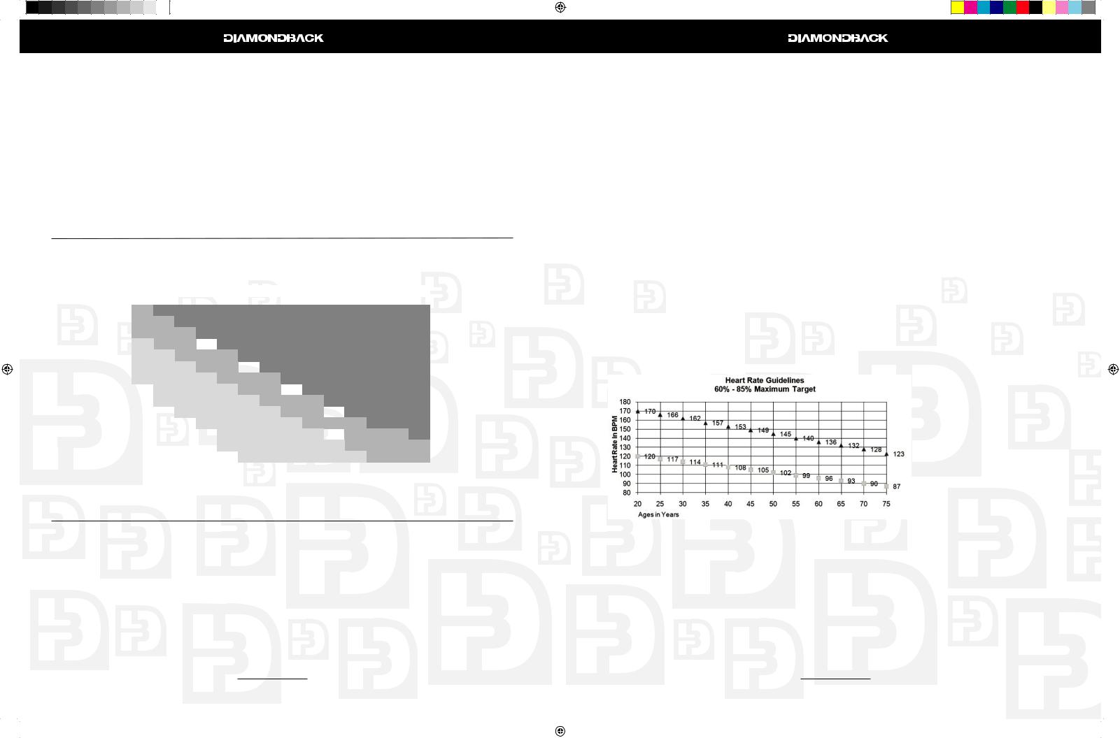
Maximum Heart Rate & Training Zone
To calculate your maximum heart rate and fi nd your training zone, use the following formula. An example has been provided below based on a 35-year –old person:
220 – Age = Maximum Heart Rate |
(220 – 35 = 185) |
|
60% of Maximum Heart Rate |
(60% x 185 |
= 111bpm) |
85% of Maximum Heart Rate |
(85% x 185 |
= 157bpm) |
Training Zone: |
111bpm – 157bpm |
|
= 85% = 60%
Quantity & Quality
It is recommended that you accumulate at least 30 minutes of physical activity most days of the week. Physical activity should be initiated slowly and the intensity should be increased gradually. You should select activities that you enjoy and can fi t into your daily life. Having Diamondback equipment at home certainly gives you the comfortable and convenient workout you want.
The American College of Sports Medicine makes the following recommendations for the quantity and
13
500Ub.Sr OM R1.indd 12-13 |
|
|
6/11/2008 9:54:28 AM |
|
|
||
|
|
|
|
 Loading...