

Page 1
01/2019
Mod: FVS-711/TS
Production code: PK-DT-107E DI
Page 2
CONVECTION OVENS - INSTRUCTIONS FOR THE INSTALLATION
EN
RHDA-104E
RHDT-104E
RHDA-107E
RHDT-107E
FMEC411M FMEC711M
FMEC411D FMEC711D
FMEC411T FMEC711T
FMEC723M FMEC1011M
FMEC723D FMEC1011D
FMEC723T FMEC1011T
FVS-423
FVS-711
FVS-423/TS
FVS-711/TS
FVS-1111/TS
RHDA-304E RHDT-304E
RHDA-104E RHDT-104E
RHDA-307E RHDT-307E
RHDA-107E RHDT-107E
RHDA-111E RHDT-111E
PK-DA-304E PK-DT-304E
PK-DA-104E PK-DT-104E
PK-DA-307E PK-DT-307E
PK-DA-107E PK-DT-107E
PK-DA-111E PK-DT-111E
B02.0026.00
Page 3
EN INDEX
Dimensions
Foreword
1.0 Declaration of Conformity
1.1
1.3
European Directive
ROHS 2012/19/UE
Transport of the oven and
packaging removal
1.4 Informative labels
INSTALLATION
1.5 Oven positioning
1.6 Electrical connection
1.7
Technical data for electrical
connection
2.3 Water features
2.4
2.5
Technical data table water
connection
Hydraulic connection
water inlet
2.6 Plumbing – water drainage
2.9 Reversal of door opening
3.0 Control and safety devices
3.1 Spare parts replacing
3.2 Checking the functions
2
Page 4
273
130,5
883
77
60 535 148
130
760
67
30 450 30
510
= =
32O
D
200
A
96
30
50 804
B
25
C
1316
114 760 23
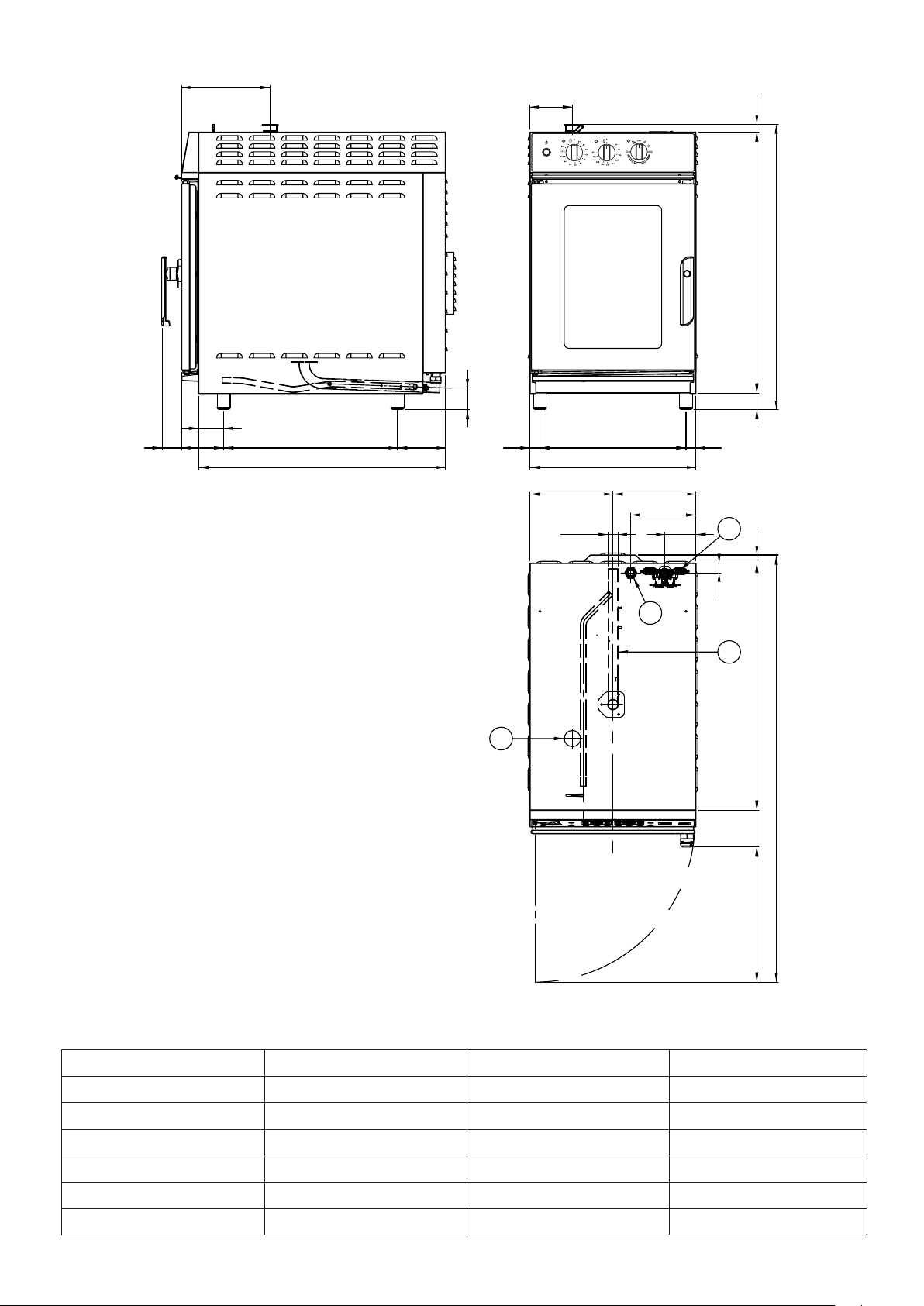
416
7 x 1/1 GN
Dimensioni Capacità Distanza teglie Peso a vuoto
Dimensions Capacity Trays distance Empty weight
Abmessungen Kapazität Einschubabstand Leergewicht
Dimensions Capacité Ecartement grilles Poids à vide
Dimensiones Capacidad Distancia bandejas Peso en vacío
Afmetingen Capaciteit Afstand dienbladen Leeggewicht
mm 510 x 812 x h 880 7 x 1/1 GN 67 mm
Page 5

EN
FOREWORD
The contents of this manual are generic and not all the functions described may be available on your
product.
The manufacturer declines all responsibility for possible inaccuracies contained in this pamphlet, due to printing
or copy errors. We reserve the right to make on our own products those changes to be considered necessary or
useful, without jeopardizing the essential characteristics.
Read the instructions for use very carefully paying particular attention to the rules concerning safety devices. This
appliance must only be used for what it has been designed for and built for and that is: all baking of dishes and
regenerating pre-cooked and/or frozen food.
WARNING!
Before making any type of connection of this equipment (electrical or hydraulic), carefully read the instructions
in this manual. This manual must be carefully kept to be available for future reference by users or service tech-
nicians. Installation must be carried out by d qualied personnel only.
1.0 DECLARATION OF CONFORMITY
The Manufacturer declares that the appliances conform to the EEC norms.
They must be installed in accordance with current standards, especially regarding aeration of the premises and
the exhaust gas evacuation system.
Note: The Manufacturer declines all and every responsibility for any direct damages caused by: an
incorrect use, wrong installation or bad maintenance.
1.1 EUROPEAN DIRECTIVE ROHS 2012/19/UE
This appliance is marked according to the European directive 2012/19/UE on Waste Electrical and Electronic
Equipment (WEEE). By ensuring this product is disposed correctly, you will help prevent potential negative consequences for the environment and human health, which could otherwise be caused by inappropriate waste handling of this product.
The symbol on the product, or on the documents accompanying the product, indicates that this
appliance may not be treated as household waste.
Instead it shall be handed over to the applicable collection point for the recycling of electrical
and electronic equipment.
Disposal must be carried out in accordance with local environmental regulations for waste disposal.
1.3 TRANSPORT OF THE OVEN AND PACKAGING REMOVAL
Upon receipt of the oven and before installing it, check the packaging is intact and there are not visible damages.
Also check that along with the oven you receive also the documentation, consisting of:
• Instructions for installation, use and maintenance
• Chart to check correct installation
• Wiring diagram
• Label ISO 3864-1
Before bringing the oven to the point, where it must be installed, check the following:
The doors are large enough to allow passage of the oven
The oor supports the weight.
According to the model of oven, its dimensions and its weight, use suitable facilities to handle goods during transport and installation, able to guarantee stability in order to avoid overturning, falls or uncontrolled movements of
the appliance or its components.
Keep the oven packed until you reach the site where the oven is going to be installed.
The packaging makes the handling of goods easier and protects the oven from accidental push.
During moving and installation of the oven, the installer must comply with accident-prevention regulations in
force at the place of installation (use of safety shoes, gloves, etc.) Remove the packaging taking care not to dam-
age the oven. The adhesive lm, that protects the surfaces made of stainless steel can be removed also after you
have positioned the oven on the corresponding stand or the support surface.
ATTENTION: Packaging materials and adhesive lm are potentially dangerous.
For this reason, they must be kept out of the reach of children and properly disposed of in compliance with local directives.
You should separate packaging materials (wood, cardboard, plastic...) and dispose of them separately, in compliance with directives in force at installation site.
Note: Take the protective lm o the stainless steel parts by hand before starting the appliance.
Do not use abrasive substances and/or metal objects. Clear any adhesive residues using a sponge soaked in sol-
vent. If the oven is heated up before removing the adhesive lm, the removal of the lm and cleaning of residues
of glue will be much more dicult.
9
Page 6

EN
1.4 INFORMATIVE LABELS
On each oven there are applied some metal labels, that give important info concerning characteristics of the oven,
electric and plumbing connections and eventually the drain connection.
On the right hand side panel there is the label A.
The info contained on this label are:
• Name and address of the manufacturer
• Oven model
• IPX protection grade against water jet.
• Conformity to EC directives.
• Power input and power supply (single or three phase).
• Serial number of the oven
• Symbol of European Directive 2012/19/UE
Removing the back side panel, on the oven chassis you nd label B.
On this label the serial number of the oven is repeated.
In this way, the customer or the installer can nd the serial number of the
oven also when the label A is dirty or damaged.
If the oven is equipped with humidication, in the back of the oven, near the
connector for water connection there is the label C.
Label C indicates water features necessary for a correct functioning of the
oven.
Same features are listed at paragraph 2.4 of this manual.
Close to the drain there is the label D, containing info concerning drain connection.
INSTALLATION
1.5 POSITIONING OF THE OVEN
The place where the oven will be installed
must comply the following requirements:
• Be protected from atmospheric agents
and have an adequate air circulation;
• Comply with regulations concerning
safety at work;
• Have a room temperature between 5
°C and 35 °C with a humidication not
higher than 70%.
• Place the oven and proceed with levelling using adjustable feet.
*Keep a suitable distance at the back,
in order the label of equipotential clamp
is easy to see when the oven has been
installed.
The same clamp must be easy to access to install equipotential cable after the oven has been installed in compliance with our instructions. Install the appliance in a position that allows access to the right side for installation, maintenance and technical assistance.
Maintain the minimum distances between the oven walls, (rear and right side) and either the brick walls or the
other appliances.
> 10 cm> 10 cm
*
10
Page 7

1.6 ELECTRICAL CONNECTION
When the appliance is delivered it is set to work at the voltage given
on the rating plate axed on the right side of the appliance.
The eectiveness of the equipotential system of which the appliance is
part of, must conform to current standards.
Connect using the screw you nd in the back side of the oven, marked
with the word EQUIPOTENTIAL.
The Manufacturer declines all and every responsibility if this important
accident prevention norm is not complied with. If the feeding cable is
damaged, it must be replaced by the technical service or in any case
by similar qualied personnel, in order to avoid any risk.
1.7 TECHNICAL DATA FOR ELECTRICAL CONNECTION
EN
Model
Power loading
and voltage
no. and motor
power
Heating
power
Absorbed
current
Feed cable
section
4.3 kW
380-415 V 3N ~
5 x 1.5 mm
2
50/60 Hz
4 x 2/3 GN
2.7 kW
220-240 V 1N ~
1 x 250 W 3.9 kW 7.5 A
3 x 1.5 mm
2
50/60 Hz
5.2 kW
4 x 1/1 GN
380-415 V 3N ~
1 x 250 W 4.9 kW 8.5 A 5 x 1.5 mm
2
50/60 Hz
5.2 kW
7 x 2/3 GN
380-415 V 3N ~
1 x 250 W 4.9 kW 8.5 A 5 x 1.5 mm
2
50/60 Hz
8.8 kW
7 x 1/1 GN
380-415 V 3N ~
1 x 250 W 8.5 kW 14.5 A 5 x 2.5 mm
2
50/60 Hz
15 kW
11 x 1/1 GN
380-415 V 3N ~
2 x 250 W 14.4 kW 25 A 5 x 4.0 mm
2
50/60 Hz
2.3 WATER FEATURES
The water must be suitable to human use with the following characteristics:
Temperature: included between 15 – 20°C
Total hardness: included between 4 and 12 °f (French degrees), it is advisable to install a softener upstream
from the appliance that will maintain the hardness level at the mentioned values.
Pressure: included between 150 and 250 KPa (1,5 – 2,5 bar).
Attention: higher water pressure values result in increased water consumption and can compromise
the correct functioning of some components.
Maximum chloride concentration (Cl-): less than 150 mg/litre.
Chlorine concentration (Cl2): less than 0.2 mg/litre.
pH: more than 7.
Water conductivity: included between 50 and 2000 µS/cm.
Attention: Water treatment systems that bring to dierent values to the ones above mentioned automatically invalidate the guarantee.
The use of dosing systems designed to prevent the build-up of lime-scale in pipes (i.e. polyphosphate dosing
systems) is also prohibited since it may impair the performance of the appliance.
2.4 TECNICAL DATA TABLE FOR THE WATER SYSTEM
4 x 2/3 GN 4 x 1/1 GN 7 x 2/3 GN 7 x 1/1 GN 11 x 1/1 GN
Water ow rate regulator for steam
generation in combined and steam
Ø 0.4 mm Ø 0.4 mm Ø 0.5 mm Ø 0.5 mm Ø 0.5 mm
cycle.
Water ow rate regulator drain steam
condenser.
Ø 0.7 mm Ø 0.7 mm Ø 0.7 mm Ø 0.7 mm Ø 0.7 mm
11
Page 8

EN
2.5 HYDRAULIC CONNECTION – WATER INLET
The ovens have a water inlet coupling at the back. Always install an on-o valve between the appliance and the
water mains, making sure it is easy to operate.
We also suggest installing a cartridge lter on the water inlet pipe.
Always use a set of new water joints, eventual old joints must not be used again.
Plumbing connection must be always eected with cold water and rigid pipes.
Never use hoses to connect the oven to the water main.
In models with 4 and 7 trays, the solenoid valve (A)
supplies the steam generation in Steam and Combi
cycles, valve (C) supplies the steam condensation
system.
In models with 10 teglie, the solenoid valve (A)
supplies the steam generation in Steam mode, (B)
in combi mode and the valve (C) supplies the steam
condensation system.
2.6 PLUMBING – WATER DRAINAGE
Drainage for the water is at the back of the oven and must be connected directly
to the end of the stainless steel drainpipe.
The drain must have no trap and be made in rigid pipes that can withstand a temperature of 110°C.
Under no circumstances must pipe diameter be reduced. The actual pipe should
be at atmospheric pressure with the appropriate funnel type air intake.
If the drainpipe is clogged for any reason steam can escape from the door and
bad smells can be created inside in the oven.
min. 2°
12
Page 9

EN
2.9 REVERSAL OF DOOR OPENING
In this oven series you can reverse the door opening also after installation, without asking for this option upon
the order of the oven. Proceed as follows:
Unscrew and remove the 2 screws indicated by the ar-
rows, that x the door to the hinges, taking care to
support the door.
Disconnect the wiring connector for the cooking
chamber lighting.
Pull the door out of hinges and lay it over a at surface
with the handle upwards.
Unscrew the 2 hinges from position A and B and screw
them again in the foreseen holes for position A1 and
B1.
Unscrew the door lock from position C and screw it
again on position C1. The holes of positions A1 B1 and
C1 are closed by protection screws. Use the screws
protecting holes A1 B1 and C1 to close the holes of
positions A, B, C.
Remove the drip pan under the door from position A
and screw it again upside down on position B.
The holes for the xing of position B are protected by
rivets, that must be removed.
After you have removed the right hand side panel,
pull out the wiring for chamber lighting and let it pass
through the hole near hinge B.
Connect the wiring connector for chamber lighting.
Fix the door upside down to hinges A and B.
13
Page 10

EN
After you have xed the door in its new position, the
handle will be upside down.
To put the door in the correct position, remove the
round little cap and unscrew the screw that blocks the
handle.
Pull out the handle and x it upside down.
Screw the xing screw again and put the little round
cap on its position.
To complete the operation, you need to x the magnetic sensor on the side of the door handle.
After you have removed the right hand side panel, x
the magnetic sensor inside the control panel on the
lower corner on the right hand side of the door.
Unscrew the sensor of the xing plate and let it pass
along with the cable under the cooking chamber until it
comes out from the left hand side of the oven.
Fix the sensor on the position indicated in the gure
here above.
After you have checked the correct functioning of the
magnetic sensor and mounted the side panels again,
you need to check if the door gasket is tight.
This operation must be carried out with oven in function.
Fix the door closure adjusting the xing screws of the
hinges and the door lock.
14
Page 11

EN
3.0 CONTROL AND SAFETY DEVICES
The ovens are equipped with a set of control and safety devices for the electric and hydraulic circuits.
3.0A 2A fuse: it is in the auxiliary circuit to protect against short circuiting of the electrical system and is in-
side its own support on the contactor’s xing bracket.
3.0D Motor overload protection: a thermal probe disengages the motor when, for various reasons, there is
an overload. When the overload protection triggers it stops the motor and also disconnects the heating elements or the gas valve. The probe is reset automatically when motor temperature drops.
3.0E Oven safety thermostat: disconnects the heating element or the gas valve when anomalies related to
overheating occur. Subsequent re-set will have to be done manually when causes for thermostat operation have
been determined.
3.0F Door micro switch: it stops the oven working when the door is opened.
3.0G Thermostat system for condensation of discharge steam: it
comprises a solenoid valve controlled by a thermostat whose sensor is
housed in contact with the discharge.
The solenoid valve, via the injector (G), lets cold water into the drainpipe
to condense the steam when a temperature of 90°C is reached.
Removing the side panel of the oven and acting on the F3 adjuster, it’s
possible to modify the condensation system in the following way: if you
turn the thermostat pin F3 counterclockwise until you hear a click, the
function is disabled.
If you turn the pin counterclockwise without reaching the limit stop, steam
condensation system activates when the temperature in the drain pipe is
around 30 °C.
If you turn the pin counterclockwise till limit stop, condensation system
activates when the temperature inside the drain is around 90 °C.
In our factory the ovens are supplied with F3 thermostat regulated at 90
°C.
3.1 REPLACING SPARE PARTS
The replacement of damaged parts must be done only by qualied personnel.
To request the manufacturer parts to be replaced must be provided the oven model and serial number.
These data can be found on the rating plate attached to the oven (see par. 1.4).
Before starting to replace spare parts make sure, for safety reasons, that the electricity main switch is o
and that the water on-o valve are closed.
3.2 CHECKING THE FUNCTIONS
After completing the installation of the oven is necessary to perform a leak test to the water network.
The installer must check with suitable measurement instruments that the air noise emissions have
a level of sound pressure type weighed A, less than 70 dB (A).
The label ISO 3864-1 here on the side must be stuck on a visible surface, 1,6 mt
height from the ground.
On oor models, the label is already stuck in the suitable position.
On table models, the label is supplied along with the documentation and must be
stuck after installation on a visible part of the appliance at 1.60 mt from the ground.
The installer must verify proper operation of the oven, providing the necessary instructions
to the customer and give this instruction manual that the user must follow carefully.
IMPORTANT:
Before the operator turns the oven on and uses it for any cooking or washing cycle, it is necessary that the install-
er or a qualied technician checks all the connections have been done up to the instructions stated in our manual.
The technician or the installer must therefore check as follows:
• The oven must stand (horizontal position) and be xed on a stand or a shelf, that can guarantee stability.
• Wiring connection must be eected according to the directives and the feed cable section must be no lower than
the one indicated in the manual.
• Pressure and hardness of the water must comply the values indicated in this manual;
• If the oven is supplied with drain pipe, this must be connected properly and the materials used should withstand
the working temperature.
After you have checked everything, open the water on-o valve, eventually the gas on-o valve and the protection switch, all installed upstream.
The installer must check the proper functioning of the oven and give to the operator necessary instructions for a
correct use of the oven, and also verify that the operator owns a copy of this manual.
At the end the installer must ll in and sign the chart for correct installation and give it to the customer, who will keep it for all warranty period of the oven.
15
 Loading...