

Page 1

01/2012
Mod: E77/F13A4-N
Production code: B-EF477
Page 2

ITALIANO ................................................................................................ pagina 2 - 10
ENGLISH ................................................................................................. page 11 - 19
FRANÇAIS ............................................................................................... page 20 - 28
DEUTSCH ................................................................................................ Seite 29 - 37
ESPAÑOL ................................................................................................ página 38 - 46
INDICE
CAPITOLO DESCRIZIONE PAGINA
Avvertenze generali ............................................................................................................................. 3
1. Dati tecnici .......................................................................................................................................... 4
1.1 Friggitrici elettriche Serie OPTIMA .................................................................................................... 4
1.2 Caratteristiche tecniche ....................................................................................................................... 4
2. Istruzioni per l’installazione ............................................................................................................... 4
2.1 Targhetta dati friggitrici elettriche Serie OPTIMA ............................................................................. 4
2.2 Leggi, norme e direttive tecniche ....................................................................................................... 5
2.3 Luogo d’installazione ......................................................................................................................... 5
2.3.1 Posizionamento ................................................................................................................................... 5
2.3.2 Montaggio apparecchiature top su base o supporto a sbalzo ............................................................ 5
2.4 Collegamento elettrico........................................................................................................................ 5
2.4.1 Messa a terra ........................................................................................................................................ 5
2.4.2 Equipotenziale .................................................................................................................................... 6
2.4.3 Cavo d’alimentazione ......................................................................................................................... 6
2.4.4 Collegamenti alla rete elettrica di distribuzione ................................................................................ 7
2.4.5 Consigli per l’installatore ................................................................................................................... 7
3. Sostituzione dei componenti più importanti ...................................................................................... 7
4. Istruzioni per l’utente .......................................................................................................................... 8
4.1 Accensione friggitrice ......................................................................................................................... 8
4.2 Temperature di cottura ........................................................................................................................ 9
4.3 Esempi di cottura................................................................................................................................. 9
4.4 Svuotamento della vasca olio ............................................................................................................. 9
4.5 Limitatore di temperatura .................................................................................................................... 9
4.6 Consigli e accorgimenti ...................................................................................................................... 10
5. Manutenzione e pulizia ...................................................................................................................... 10
SCHEMI DI INSTALLAZIONE ........................................................................................................... 47
SCHEMA ELETTRICO E77/F13-A4-E77/F12-A4T .......................................................................... 49
SCHEMA ELETTRICO E77/F26-A7 - E77/F24-A7T ....................................................................... 50
SCHEMA ELETTRICO E77/F13-A4 2V - E77/F13-A4 2VT ............................................................. 51
- 2 -
Page 3

AVVERTENZE GENERALI
- Leggere attentamente le avvertenze contenute nel presente libretto in quanto forniscono importanti
indicazioni riguardanti la sicurezza di installazione, d’uso e di manutenzione.
- Conservare con cura questo libretto per ogni ulteriore consultazione dei vari operatori.
- Dopo aver tolto l’imballaggio, assicurarsi dell’integrità dell’apparecchiatura e in caso di dubbio, non utilizzare
l’apparecchiatura e rivolgersi a personale professionalmente qualificato.
- Prima di collegare l’apparecchiatura, accertarsi che i dati riportati sulla targhetta siano corrispondenti a quelli della
rete di distribuzione elettrica.
- Questa apparecchiatura deve essere destinata solo all’uso per il quale è stata espressamente concepita, ogni
altro uso è da considerarsi improprio e quindi pericoloso.
- L’app arecchiatura deve essere utilizzata solo da persona addestrata all’uso della stessa.
- Per eventuale riparazione rivolgersi solamente ad un centro di assistenza tecnica autorizzato dal costruttore e
richiedere l’utilizzo di ricambi originali.
- Il mancato rispetto di quanto sopra, può compromettere la sicurezza dell’apparecchiatura.
- Non lavare l’apparecchiatura con getti d’acqua diretti e ad alta pressione.
- Non ostruire le aperture o feritoie di aspirazione o di smaltimento del calore.
- La sicurezza elettrica è garantita soltanto da un efficace impianto di messa a terra, come previsto dalle
vigenti norme di sicurezza elettrica, è quindi necessario verificare questo fondamentale requisito, e in
caso di dubbio, richiedere il controllo accurato da parte di personale professionalmente qualificato.
- Il costruttore non può essere considerato responsabile per eventuali danni causati dalla mancanza di
messa a terra dell’impianto.
- L’apparecchiatura deve essere inclusa in un sistema equipotenziale la cui efficienza deve essere verificat a secondo
le norme in vigore.
- Tutte le apparecchiature sono fornite di cavo, della lunghezza di m. 2, con caratteristiche come specificato in T ab. 2.
- Il cavo flessibile per l’allacciamento alla linea elettrica deve avere caratteristiche non inferiori al tipo con isolamento
in gomma H07RN-F .
- In caso di inosservanza delle norme contenute nel presente manuale, sia da parte dell’utente che da
parte del tecnico addetto all’installazione, la Ditta declina ogni responsabilità ed ogni eventuale incidente
o anomalia causato dalle suddette inosservanze non potrà essere imputato alla stessa.
In caso di inosservanza delle norme contenute nel presente manuale, sia da parte dell’utente che da parte del tecnico
addetto all’installazione, la Ditta declina ogni responsabilità ed ogni eventuale incidente o anomalia causato dalle
suddette inosservanze non potrà essere imputato alla stessa.
La casa costruttrice declina ogni responsabilità per le possibili inesattezze contenute nel presente opuscolo, imputabili ad
errori di trascrizione o stampa. Si riserva inoltre il diritto di apportare al prodotto quelle modifiche che si ritengono utili o
necessarie, senza pregiudicare le caratteristiche essenziali.
- 3 -
Page 4
1. DATI TECNICI
1.1 FRIGGITRICI ELETTRICHE SERIE OPTIMA
DIMENSIONI IN mm.
MODELLO
E77/F12-A4T
E77/F2V6-A4T
E77/F24-A7T
E77/F13-A4
E77/F2V7-A4
E77/F26-A7
*TENSIONE DI ALIMENT AZIONE: 3N AC 400 V; 3 AC 230 V ; 1N AC 230 V 50/60 Hz.
N.B.: La potenza assorbita con 3N AC 380 V; 3 AC 220 V; 1N AC 220 V 50/60 Hz è circa del 9% inferiore ai valori riportati.
La potenza assorbita con 3N AC 415 V; 3 AC 240 V; 1N AC 240 V 50/60 Hz è circa del 9% superiore ai valori riportati.
ESTERNO
L x P x A/A max.
400 x 700 x 290/425
400 x 700 x 290/425
700 x 700 x 290/425
400 x 700 x 850 x 985
400 x 700 x 850 x 985
700 x 700 x 850 x 985
V ASCA
Ltr.
12
6 + 6
12 + 12
13
7 + 7
13 + 13
POTENZA
ASSORBITA*
TOT ALE
kW
9
10,5
9 + 9
9
10,5
9 + 9
PESO
NETTO
kg.
30
35
45
60
60
80
T ab. 1
1.2 CARATTERISTICHE TECNICHE
STRUTTURA
Struttura portante in acciaio inox AISI 304, pannellatura e basamento in acciaio inox, montata su piedini regolabili in altezza.
VASCA in acciaio inox AISI 304.
TERMOSTATO ELETTRICO per comando resistenze (60 ÷ 200°C) per una regolazione ottimale della temperatura.
RESISTENZE ELETTRICHE in incoloy.
MANOPOLE COMANDI in materiale atermico.
2. ISTRUZIONI PER L’INSTALLAZIONE
L’installazione deve essere eseguita da persone qualificate secondo la normativa in vigore.
AVVERTENZE:
Nel caso in cui l’apparecchiatura venga installata contro una parete quest’ultima deve resistere ai valori di temperatura di
100°C e deve essere incombustibile.
Prima di procedere all’installazione, togliere dal rivestimento la pellicola di protezione in plastica, eliminando gli eventuali
residui adesivi con prodotto adatto alla pulizia per l’acciaio inossidabile.
Installare l’apparecchio in posizione orizzontale, la corretta posizione si otterrà ruotando i piedini livellatori.
Qualora l’apparecchiatura venga installata singolarmente si consiglia di fissarla per rendere più sicura la sua stabilità.
2.1 TARGHETTA DATI FRIGGITRICI ELETTRICHE SERIE OPTIMA
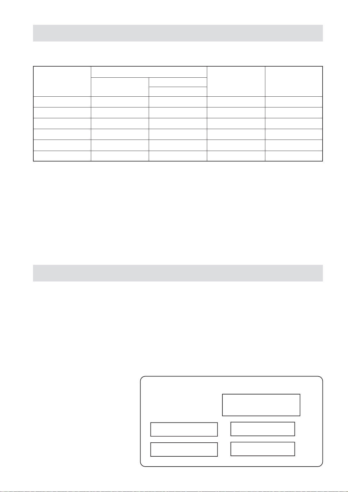
La targhetta dei dati tecnici si trova:
a)negli apparecchi con armadio, nell’armadio in basso a sinistra e all’interno.
b)negli apparecchi senza armadio, sul retro
ed all’interno.
Mod.
Matr. N°
V
HZ
- 4 -
KW
Page 5
2.2 LEGGI, NORME E DIRETTIVE TECNICHE
Per l’installazione sono da osservare le seguenti norme:
- Prescrizioni vigenti antinfortunistiche e antincendio.
- La regolamentazione dell’ente distributore energia elettrica.
- Norme igieniche.
- Norme impianti elettrici.
2.3 LUOGO D’INSTALLAZIONE
- L’apparecchio deve essere installato in locali con sufficiente areazione.
- Installare l’apparecchiatura secondo quanto previsto dalle norme di sicurezza.
2.3.1 POSIZIONAMENTO
- Le varie apparecchiature possono essere installate singolarmente o possono essere accoppiate ad altre apparecchiature
della stessa gamma OPTIMA.
- Questa apparecchiatura non è idonea per l’incasso.
- La distanza dalla pareti laterali deve essere minimo di 10 cm., nel caso in cui la distanza fosse inferiore o il materiale delle
pareti o del pavimento fossero infiammabili, è indispensabile l’applicazione di un isolante termico.
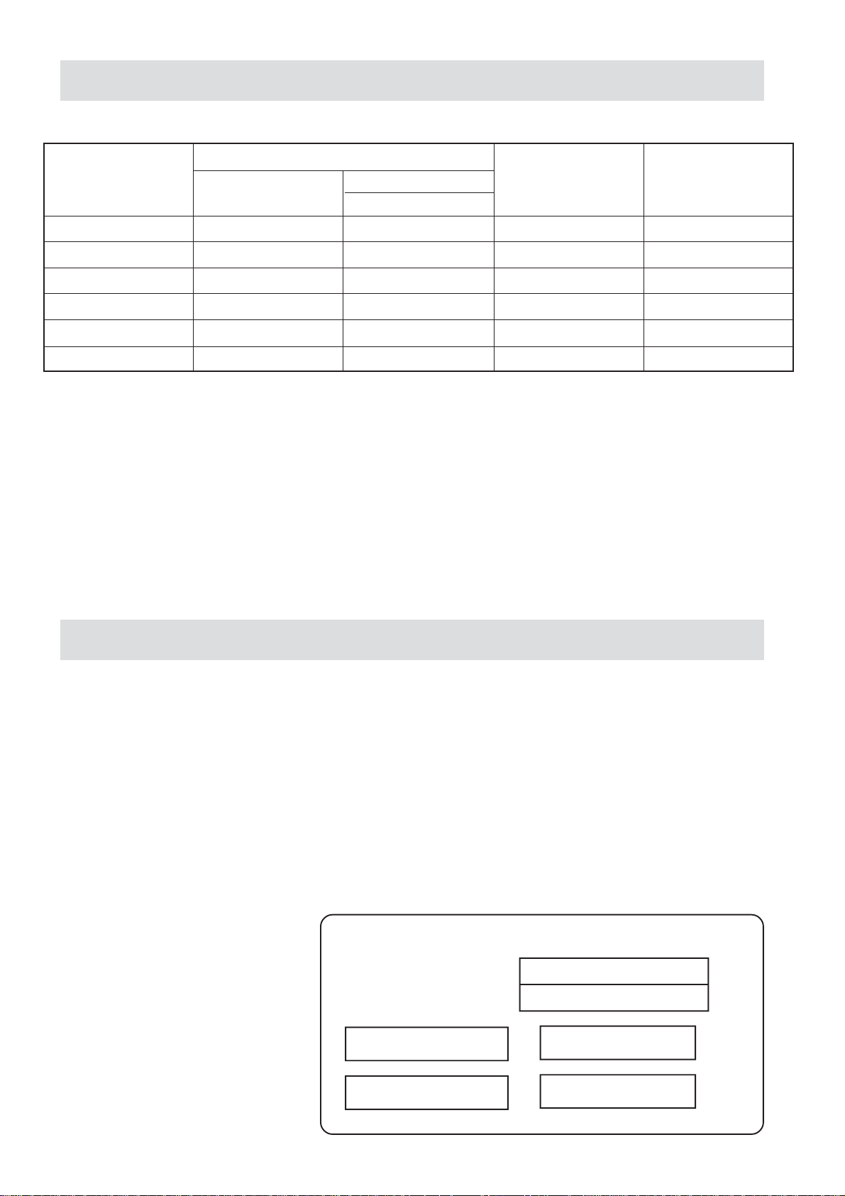
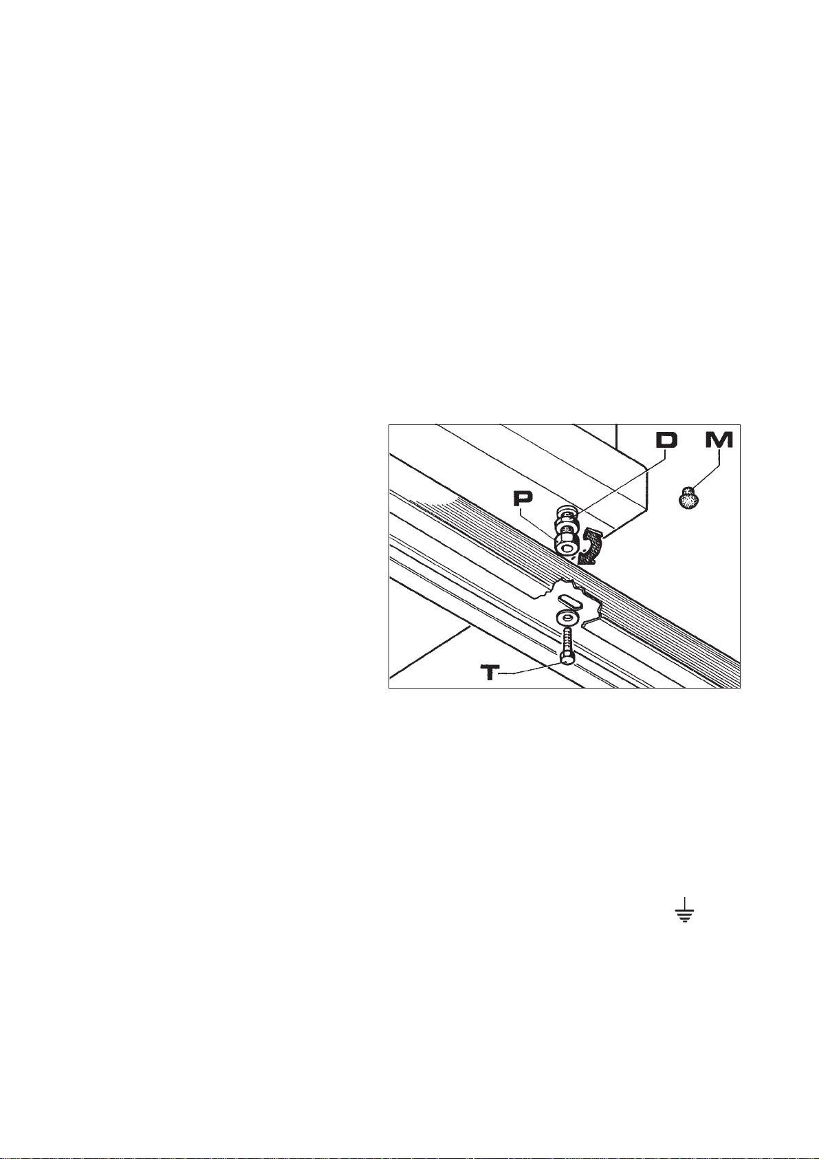
2.3.2 MONTAGGIO APPARECCHIATURE TOP SU BASE O SUPPORTO A SBALZO
Tutte le apparecchiature top sono munite di piedini
regolabili in altezza (P):
- Quando l’apparecchiatura deve essere sistemata libera
su un tavolo o un piano, avvitare o svitare i piedini (P)
come indicato in figura sino a farla appoggiare
perfettamente, quindi stringere il controdado (D) in modo
da bloccare il piedino. Per impedirle di scivolare, infilare
nei buchi inferiori dei piedini i tappi in gomma (M).
- Quando l’apparecchiatura deve essere fissata su una
base o su un supporto a sbalzo, regolare i piedini (P)
sino a farla appoggiare perfettamente, stringere poi il
controdado (D) in modo da bloccare il piedino. Fissare
quindi da sotto mediante viti M5 (T) con relative
rondelle avvitandole ai piedini come indicato in figura.
2.4 COLLEGAMENTO ELETTRICO
L’allacciamento elettrico dev’essere eseguito nel rispetto delle norme CEI, solo da personale autorizzato e competente.
In primo luogo esaminare i dati riportati nella tabella dati tecnici del presente libretto, nella targhetta e nello schema elettrico.
L’allacciamento previsto è del tipo fisso.
IMPORTANTE: A monte di ogni apparecchiatura è necessario prevedere un dispositivo di interruzione omnipolare della
rete, che abbia una distanza di contatti di almeno 3 mm., esempio:
- interruttore manuale di adatta portata, corredato di valvole fusibile
- interruttore automatico con relativi relè magnetotermici.
2.4.1 MESSA A TERRA
E’ indispensabile collegare a terra l’apparecchiatura.
A tale proposito è necessario collegare i morsetti, contraddistinti dai simboli ( ) posti sulla morsettiera arrivo linea, ad una
efficace terra, realizzata confermemente alle norme in vigore.
AVVERTENZE SPECIFICHE
La sicurezza elettrica di questa appartecchiatura è assicurata soltanto quando la stessa è correttamente collegata ad un
efficace impianto di messa a terra come previsto dalle vigenti norme di sicurezza elettrica; il costruttore declina, ogni
responsabilità qualora queste norme antinfortunistiche non vengano rispettate.
E’ necessario verificare questo fondamentale requisito di sicurezza e, in caso di dubbio, richiedere un controllo accurato
dell’impianto da parte di personale professionalmente qualificato.
Il costruttore non può essere considerato responsabile per eventuali danni causati dalla mancanza di messa a terra
dell’impianto.
ATTENZIONE: NON INTERROMPERE MAI IL CAVO DI TERRA (Giallo-verde).
- 5 -
Page 6
2.4.2 EQUIPOTENZIALE
L’apparecchiatura deve essere inclusa in un sistema equipotenziale la cui efficienza deve essere verificata secondo le norme
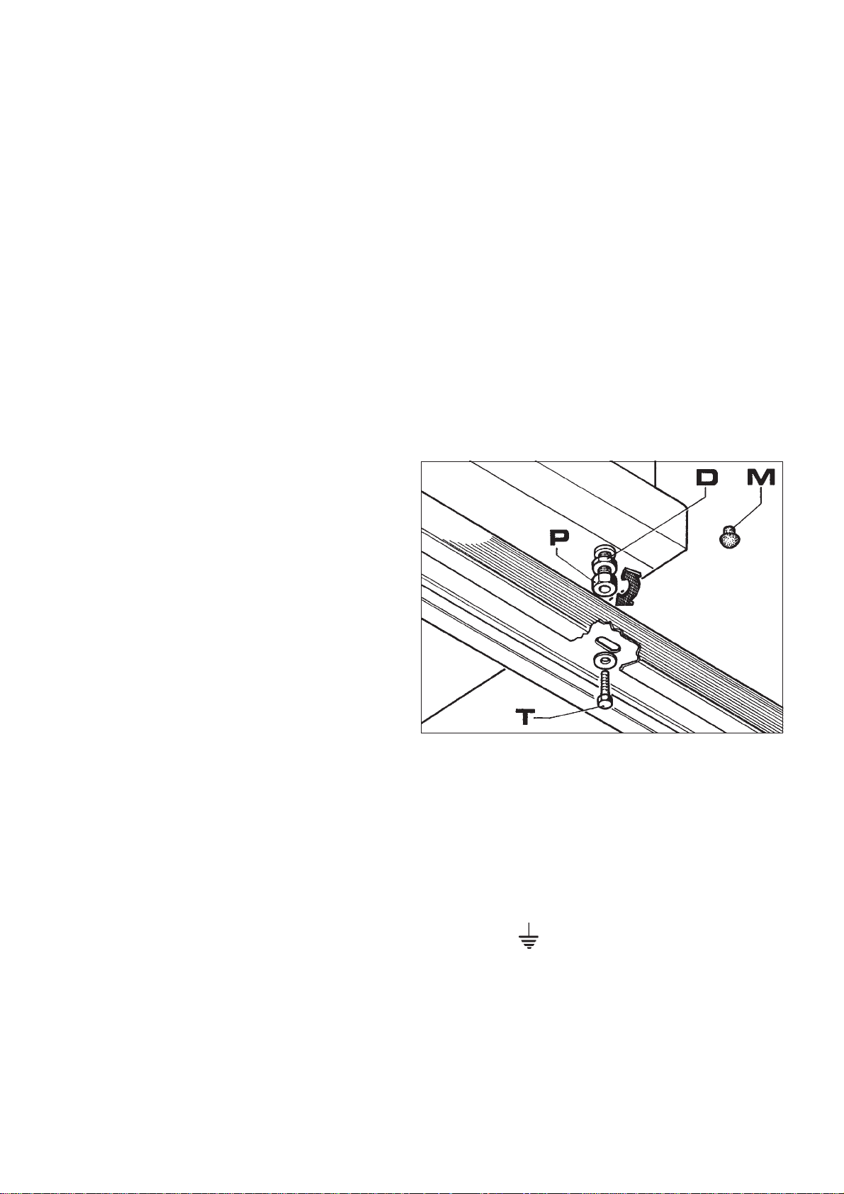
in vigore. La vite contrassegnata con la targhetta «Equipotenziale» si trova vicina alla morsettiera sul basamento nei modelli
con forno e sul retro nei restanti modelli.
2.4.3 CAVO D’ALIMENTAZIONE
L’apparecchiatura viene consegnata predisposta per una delle seguenti tensioni, 3N AC 380...415 V; 3 AC 220...240 V;
1N AC 220...240 V 50/60 Hz.
Il cavo flessibile per l’allacciamento alla linea elettrica deve essere di caratteristiche non inferiori al tipo con isolamento in
gomma H07RN-F. Il cavo deve essere introdotto attraverso il ferma cavo e fissato bene. Inoltre la tensione di alimentazione,
ad apparecchio funzionante, non deve discostarsi dal valore della tensione nominale ± 10%.
Per accedere alla morsettiera onde collegare l’apparecchiatura ad una rete d’alimentazione avente caratteristiche diverse da
quelle previste, o per sostituire il cavo d’alimentazione, occorre:
- smontare il pannello frontale (top o top + armadio)
- collegare il cavo d’alimentazione alla morsettiera secondo le necessità, seguendo le indicazioni riportate sull’apposita
etichetta collocata vicino alla morsettiera e nel presente libretto.
MODELLO
TIPO DI TENSIONE
3N AC 380...415 V 50/60 Hz
2N AC 380...415 V 50/60 Hz
3 AC 220...240 V 50/60 Hz
AC 220...240 V 50/60 Hz
NUMERO CAVI
D’ALIMENTAZIONE
SCHEMA ELETTRICO
DISEGNO N
E77/F13-A4
E77/F12-A4T
Mass.
A/fase
13
26
22,6
39
1
1345
N° cavi
mm
5 x 1,5
4 x 2,5
4 x 2,5
3 x 4
E77/F26-A7
2
Mass.
A/fase
13
26
22,6
39
2
1346
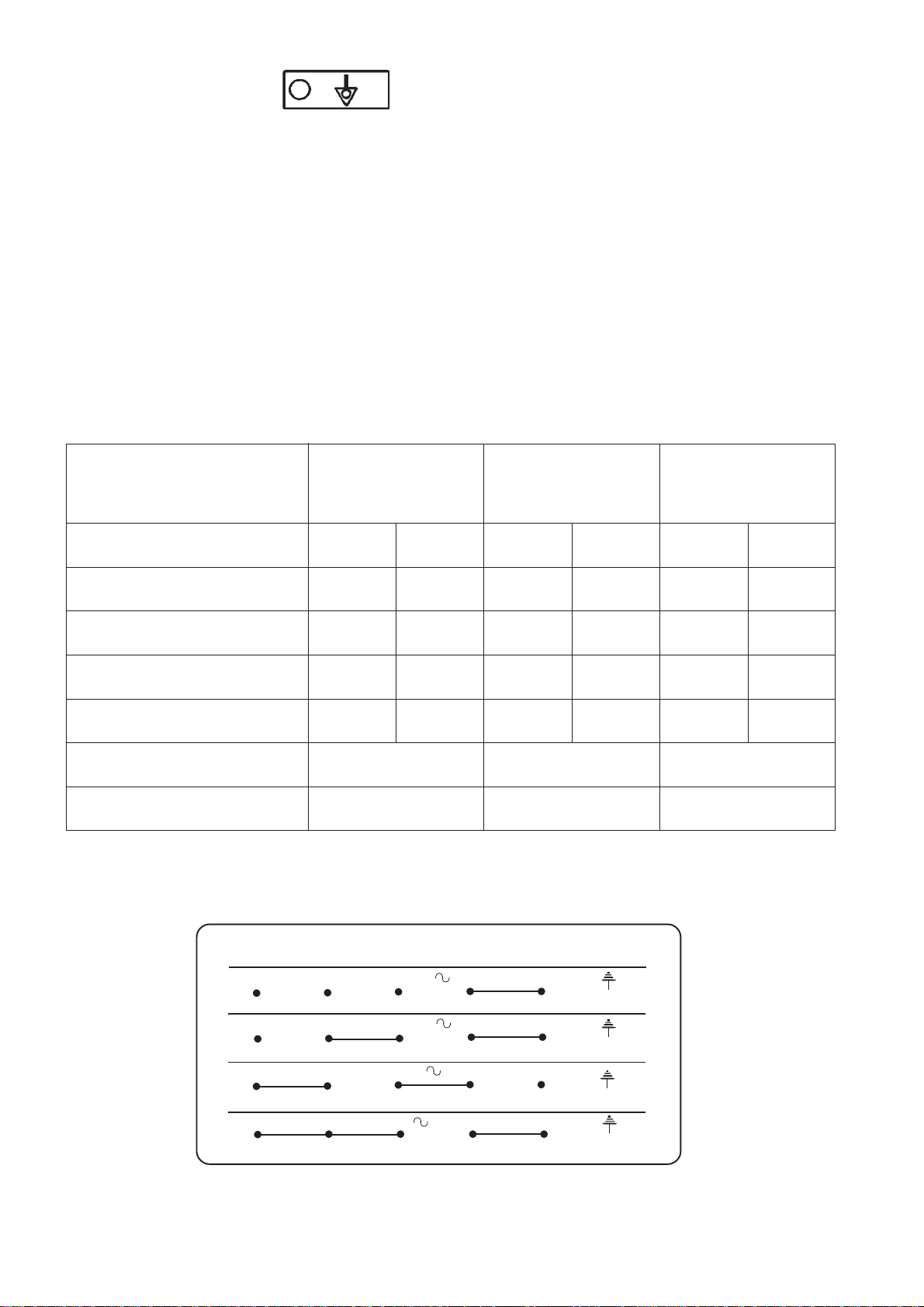
La targhetta dei tipi di collegamento elettrico si trova in prossimità della morsettiera.
N° cavi
mm
5 x 1,5
4 x 2,5
4 x 2,5
3 x 4
E77/F2V7-A4
E77/F2V6-A4T
2
Mass.
A/fase
15,2
30
26,3
45,7
N° cavi
mm
5 x 1,5
4 x 2,5
4 x 2,5
3 x 4
2
1
1347
T ab. 2
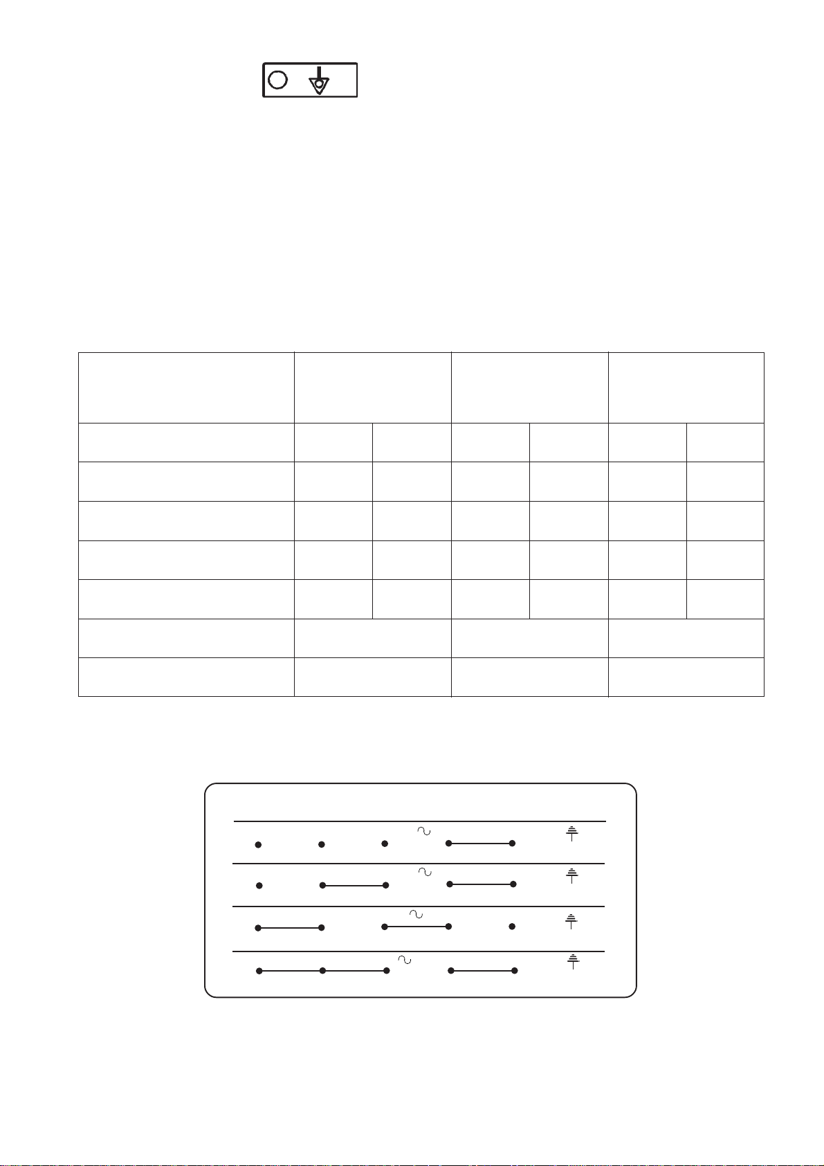
1
L1
L1
L1 N PE
L1
23456
380...415 V 3N 50/60 Hz
L2 L3 N PE
380...415 V 2N 50/60 Hz
L2 N PE
220...240 V 3 50/60 Hz
220...240 V 50/60 Hz
NPE
- 6 -
Page 7
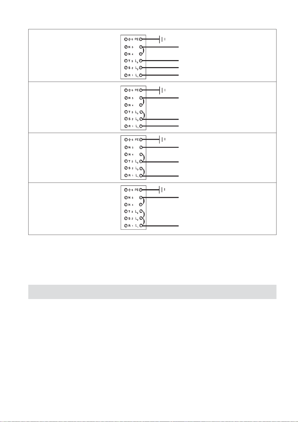
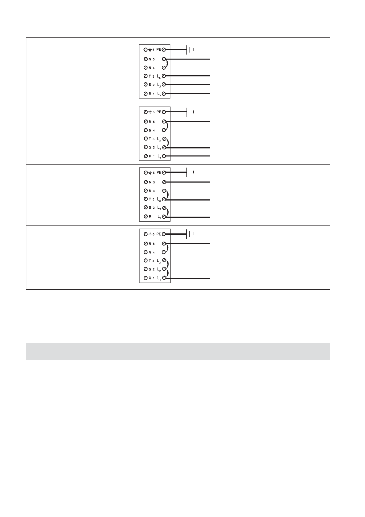
2.4.4 COLLEGAMENTI ALLA RETE ELETTRICA DI DISTRIBUZIONE
PE (Terra) giallo-verde
3N AC 380...415 V 50/60 Hz
Elementi 230 V
2N AC 380...415 V 50/60 Hz
Elementi 230 V
N (NP) azzurro
L3 (T) nero
L2 (S) nero
L1 (R) marrone
PE (Terra) giallo-verde
N (NP) azzurro
L2 (S) nero
L1 (R) marrone
3AC 220...240 V 50/60 Hz
Elementi 230 V
1N AC 220...240 V 50/60 Hz
Elementi 230 V
PE (Terra) giallo-verde
L3 (T) azzurro
L2 (S) nero
L1 (R) marrone
PE (Terra) giallo-verde
N (NP) azzurro
L1 (R) marrone
Tab. 3
2.4.5 CONSIGLI PER L’INSTALLATORE
- Mettere in funzione l’apparecchio secondo le istruzioni d’uso e spiegare il funzionamento all’utente utilizzando il
libretto istruzioni e illustrando eventuali modifiche costruttive e/o funzionali.
Lasciare il libretto istruzioni all’utente spiegando che lo deve utilizzare per ogni ulteriore consultazione.
3. SOSTITUZIONE DEI COMPONENTI PIÙ IMPORTANTI
Le sostituzioni sottoriportate vanno eseguite solo da un “Centro Assistenza autorizzato”.
Prima di eseguire le sostituzioni dei componenti, si deve togliere tensione all’apparecchio tramite l’interruttore omnipolare.
A) Commutatore e termostato
- smontare il cruscotto
- svitare le viti che fissano il componente
- rimuovere il bulbo del termostato sfilandolo dal portabulbo (solo per il termostato).
- scollegare i fili tenendo in considerazione lo schema elettrico
- sostituire il componente e riassemblare il tutto, utilizzando lo schema elettrico.
- rimontare il tutto seguendo l’ordine inverso di smontaggio.
B) Resistenze
- smontare il cruscotto
- togliere la flangia “Segger” per il bloccaggio della resistenza
- staccare i cavi seguendo lo schema elettrico, lasciando quello di protezione per ultimo
- rimuovere i bulbi dalle loro sedi
- sfilare il gruppo di riscaldamento dalla vasca
- rimontare il tutto seguendo l’ordine inverso.
- 7 -
Page 8
4. ISTRUZIONI PER L’UTENTE
Premessa
Prima di mettere in funzione l’apparecchiatura, lavare accuratamente la vasca ed i cestelli, operando come segue:
- Riempire la vasca fino a livello con acqua e detersivo, mettere in funzione il riscaldamento e portare in ebollizione per
alcuni minuti, scaricare l’acqua attraverso, il rubinetto di scarico e risciacquare abbondantemente la vasca con acqua
pulita.
- Se per friggere si usa del grasso, non metterlo nella vasca se non è allo stato liquido; dopo l’uso scaricare il grasso
quando è ancora liquido.
- Quando si deve scaldare lo strutto solido, occorre farlo molto lentamente, forando spesso la superficie del grasso per
favorirne la dilatazione e lo scioglimento.
- Durante l’uso si raccomanda di non coprire la vasca o versare all’interno sali o aromi.
- Non mettere mai in funzione l’apparecchiatura prima di aver riempito d’olio il recipiente. La mancata avvertenza
di tale norma arrecherebbe gravi danni per il surriscaldamento della vasca e delle resistenze.
RIEMPIMENTO VASCA
Assicurarsi che il rubinetto di scarico sia chiuso e che la vasca sia pulita, quindi versare l’olio per friggere fino ad un livello
compreso tra la tacca del MIN. e quella del MAX. Per la capacità della vasca vedere la tabella dei dati tecnici 1.1.
ATTENZIONE: Il livello dell’olio alla temperatura massima aumenta di circa 1 cm. rispetto al livello a freddo.
RIEMPIMENTO DEL CESTELLO
La quantità di cibo da mettere nel cesto dipende da come si vuole cucinarla. Al momento dell’immersione nell’olio bisogna
evitare un rapido abbassamento della sua temperatura evitando comunque che scenda al di sotto dei 160 °C. Piccoli pezzi di
cibo cucinati per il giusto tempo, risultano comunque migliori di un grosso pezzo che deve essere cotto per più lungo tempo.
4.1 ACCENSIONE FRIGGITRICE
Dopo aver riempito la vasca fino ad un livello compreso
tra le due tacche:
- Azionare l’interruttore omnipolare a monte dell’apparecchio. (E77/F13-A4; E77/F12-A4T; E77/F26-A7)
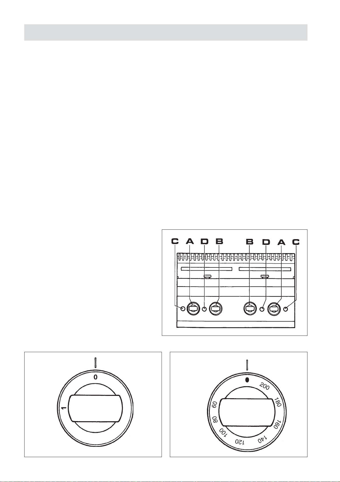
- Accendere l’apparecchio ruotando la manopola (A) e
Fig. 1 e impostare la temperatura ruotando la manopola
(B) e Fig. 2 del termostato portandola alla temperatura
desiderata: la spia verde (C) e spia gialla (D) sono
accese. (E77/F2V7-A4; E77/F2V6-A4T)
- Accendere l’apparecchio ruotando la manopola Fig. 2
impostando la temperatura desiderata, la spia verde (C)
e la spia gialla (D) sono accese.
- Raggiunta la temperatura impostata; la spia gialla (D)
si spegne.
- Se l’apparecchio non viene usato è opportuno che venga
spento anche l’interruttore onnipolare.
Fig. 1 Fig. 2
- 8 -
Page 9
4.2 TEMPERATURE DI COTTURA
La temperatura ottimale dell’olio va dai 160° ai 190°C (vedi la tabella riportata al punto 4.3). Naturalmente, se si hanno in
vasca 180°C, quando viene immesso il cesto col cibo la temperatura scende. A parità di peso più i pezzi di cibo sono grossi,
più il calo della temperatura è evidente e maggiore diventa il termpo di cottura. Con il brusco abbassamento della temperatura
si cucina in modo anomalo perchè il cibo rimanendo per un tempo più lungo immerso nell’olio, assorbe più grasso e perde in
aroma e morbidezza. Cucinando a temperature troppo alte, invece, molto spesso si ottiene una crosta dura sulla superficie
esterna dei pezzi di cibo e un’insufficiente cottura all’interno. Se l’olio o il grasso raggiungono una temperatura troppo
elevata insorge una deformazione molecolare del cibo che può provocare danni all’organismo che lo ingerisce.
4.3 ESEMPI DI COTTURA
CIBO
Crostini
Gamberi e totani
Filetto di pesce impanato
Frittura mista
Salsicce
Polli
Polli novelli
Arrosti vari (da 1 a 2 kg)
Patatine e spicchi
Doratura di patate a spicchi
Fondi di carciofi, melanzane, cavolfiori, zucchini
Frittelle
Crocchette di riso
TEMPO IN MINUTI TERMOST ATO °C
1
2 - 5
2 - 4
3 - 5
2 - 4
10 - 15
5 - 8
20 - 25
3 - 5
1 - 2
2 - 4
2 - 4
3 - 5
180
180
190
190
170 - 180
170 - 180
180
170
190
190
190
180
160 - 180
4.4 SVUOTAMENTO DELLA VASCA OLIO
Friggitrici su armadio
Per svuotare la vasca, aprire l’apposito rubinetto, l’olio scorrerà automaticamente attraverso un filtro nella bacinella raccogliolio.
È necessario verificare periodicamente che il livello dell’olio nella bacinella raccogliolio non raggiunga l’orlo e che il filtro
sia pulito.
Se necessario procedere al suo svuotamento e/o alla pulizia del filtro.
Una maniglia estraibile sul bordo superiore facilita l’estrazione e lo svuotamento della bacinella raccogliolio con entrambe
mani.
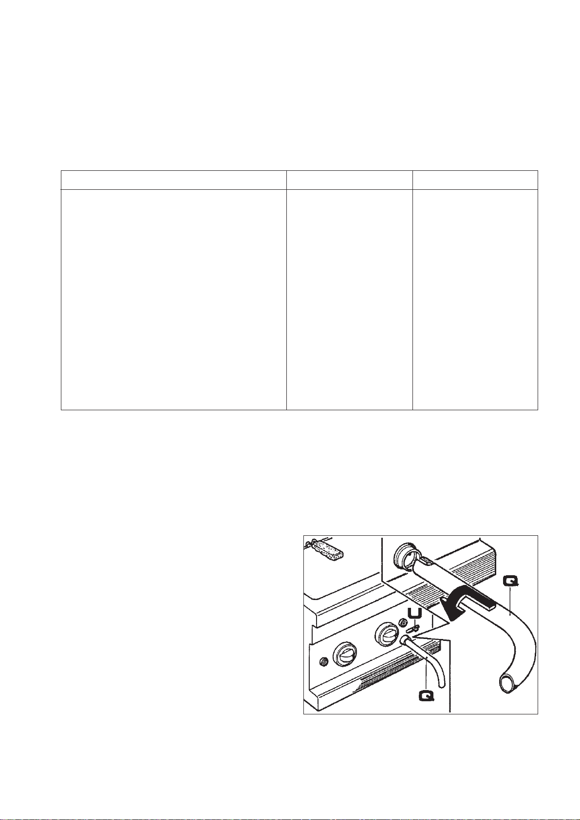
Per friggitrici su top (Fig. 3)
Per effettuare questa operazione bisogna inserire nel rubinetto di scarico l’apposita prolunga (Q), con innnesto a baionetta, data in dotazione. Posizionare un recipiente per il recupero
dell’olio, quindi alzare la leva di sicurezza ed aprire il rubinetto tirando verso sinistra la manopolina (U).
Attenzione: é consigliabile che tale operazione venga eseguita con olio freddo.
Fig. 3
4.5 LIMITATORE DI TEMPERATURA
Le friggitrici sono dotate di un termostato di sicurezza che interviene in caso di surriscaldamento dell’olio.
Quando questo è intervenuto, per far ripartire l’apparecchio occorre riarmare il termostato. Questa operazione deve essere
effettuata da personale qualificato, che accerterà la causa del suo intervento.
- 9 -
Page 10
4.6 CONSIGLI E ACCORGIMENTI
- Si raccomanda che l’olio o il grasso che vengono usati per la cottura siano di buona qualità e sempre esenti da impurità;
queste debbono essere limitate mediante filtrazione.
- Prima di versare l’olio fresco o filtrato nella vasca accertarsi che questa sia stata pulita a fondo.
- Mettere il coperchio all’apparecchio quando questo non viene usato.
5. MANUTENZIONE E PULIZIA
- Pulire giornalmente la parti in acciaio inox con acqua tiepida saponata, quindi risciacquare abbondantemente ed asciugare
con cura. La lucentezza viene mantenuta ripassando periodicamente con un opportuno detergente.
- Evitare nel modo più assoluto di pulire l’acciaio inox con paglietta, spazzola o raschietti di acciaio comune in quanto
possono depositare particelle ferrose che ossidandosi provocano punti di ruggine. Può essere eventualmente adoperata
lana di acciaio inossidabile passata nel senso della satinatura.
- Qualora l’apparecchiatura non venga utilizzata per lunghi periodi, passare energicamente su tutte le superfici in acciaio
un panno leggermente imbevuto di olio di vaselina, in modo da stendere un velo protettivo. Arieggiare periodicamente i
locali.
VASCHE DI COTTURA
Scollegare la macchina dalla corrente.
Svuotare le vasche dall’olio facendolo scendere attraverso il
rubinetto di scarico nella vasca raccogli olio.
Togliere il coperchio, cestini e retina alloggiati sopra la resi-
stenza.
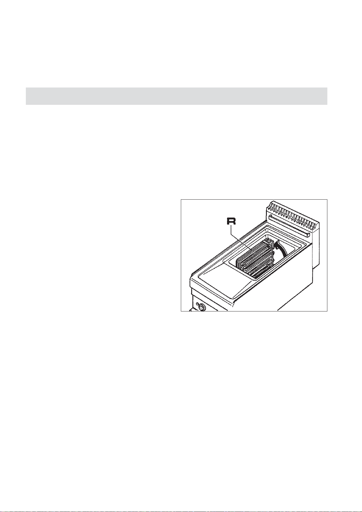
Effettuare la manovra sulla resistenza SOLO a macchina
fredda.
Ruotare le resistenze R manualmente.
Il microinterruttore, interrompe l’afflusso di corrente.
Con gli elementi riscaldanti in posizione verticale è possibile
una totale ed accurata pulizia della vasca.
Attenzione: prima di scaricare l’olio, attendere che sia
freddo; i grassi vanno scaricati allo stato liquido.
Pulire periodicamente il filtro. Si consiglia di usare oli o grassi di buona qualità, esenti da impurità eventualmente eliminate mediante filtrazione.
Mettere il coperchio quando l’apparecchio non viene usato.
Fig. 4
- 10 -
Page 11

CONTENTS
SECTIONS DESCRIPTION PAGES
General notices .................................................................................................................................... 12
1. Technical data ..................................................................................................................................... 13
1.1 Electric heated deepfat fryers series OPTIMA .................................................................................... 13
1.2 Technical characteristics ..................................................................................................................... 13
2. Installation instructions ...................................................................................................................... 13
2.1 Data plate for electric heated deepfat fryers series OPTIMA .............................................................. 13
2.2 Laws, regulations and technical directives ......................................................................................... 14
2.3 Installation place ................................................................................................................................. 14
2.3.1 Positioning .......................................................................................................................................... 14
2.3.2 Mounting the top units on a base or a next ending support .............................................................. 14
2.4 Electrical connection .......................................................................................................................... 14
2.4.1 Earthing ............................................................................................................................................... 14
2.4.2 Equipotential....................................................................................................................................... 15
2.4.3 Power supply cable .............................................................................................................................. 15
2.4.4 Connections to various main power supplies ..................................................................................... 16
2.4.5 Advice to fitters ................................................................................................................................... 16
3. Replacing the most important components ........................................................................................ 16
4. User instructions .................................................................................................................................. 17
4.1 Switching on the fryer ......................................................................................................................... 17
4.2 Cooking temperatures ......................................................................................................................... 18
4.3 Cooking examples .............................................................................................................................. 18
4.4 Draining the oil tank ........................................................................................................................... 18
4.5 Temperature limiter ............................................................................................................................. 18
4.6 Suggestions and advice ....................................................................................................................... 19
5. Maintenance and cleaning .................................................................................................................. 19
INSTALLATION DIAGRAM ............................................................................................................... 47
ELECTRICAL DIAGRAM E77/F13-A4-E77/F12-A4T ..................................................................... 49
ELECTRICAL DIAGRAM E77/F26-A7-E77/F24-A7T ..................................................................... 50
ELECTRICAL DIAGRAM E77/F13-A4 2V-E77/F13-A4 2VT .......................................................... 51
- 11 -
Page 12

GENERAL NOTICES
- Carefully read the instructions contained in the present booklet as they supply important information relating to
safe installation, use and maintenance.
- Keep this booklet with care, for any further consultation by the various operators.
- Having removed the packing, make sure the unit is in good order and in case of doubt, do not use the unit, but call
on skilled personnel.
- Before connecting the unit, make sure the data appearing on the serial plate correspond to those of the main
electric supply.
- The unit must be used only by a person trained for its operation.
- Before performing cleaning or servicing operations, disconnect the unit from the electric supply.
- Shut off the unit in case of fault or bad functioning. For any repairs, please call exclusively an authorised technical
service centre, and ask for original spare parts only . Non compliance with the above may compromise the unit’s
safety.
- This unit must only be used for the purpose it was expressly built for.
- Do not wash the unit with direct or high-pressure water jets.
- Do not obstruct openings or draft grids or heat vents.
- Electrical safety is guaranteed only by an efficient earthing system, as envisaged by the electrical safety
regulation in force: it is therefore necessary to verify this essential requisite and, in case of doubt,
request an accurate check-up by professionally qualified personnel.
- The Manufacturer cannot be deemed responsible for any damages caused by the lack of earthing in the
system.
- The unit must be included in an equipotential system whose efficiency should be tested in compliance with the law
in force.
- All units are supplied with a 200cm long cable having the characteristics shown in Tab. 2.
- The hook-up wire for the power supply connection should not have characteristics below the type with rubber
insulation H07RN-F .
- In case of non-compliance with the indications contained in the present manual, both on the user’s part
and on the installing technician’s part, the Manufacturer declines any responsibility, and any possible
accident or fault caused by the above mentioned non-compliances will not be imputable to the
Manufacturer.
In the event of the user or the installation technician failing to observe the instructions given in this manual, the Firm
disclaims all responsibility thereof and cannot be held liable for any accidents or trouble caused by such non-observance.
THE MANUFACTURER DISCLAIMS ALL RESPONSIBILITY FOR ANY INACCURACIES IN THIS BOOKLET THAT MAY BE
DUE TO TYPING OR PRINTING MISTAKES. THE MANUFACTURER, MOREOVER, RESERVES THE RIGHT TO MAKE THE
MODIFICATIONS TO THE PRODUCT IT CONSIDERS USEFUL OR NECESSARY, WITHOUT AFFECTING ITS BASIC FEATURES.
- 12 -
Page 13
1. TECHNICAL DATA
1.1 ELECTRIC HEATED DEEPFAT FRYERS SERIES OPTIMA
DIMENSIONS mm.
EXTERNAL T ANKMODEL
L x P x A/A max.
E77/F12-A4T
E77/F2V6-A4T
E77/F24-A7T
E77/F13-A4
E77/F2V7-A4
E77/F26-A7
*Feeding Power: 3N AC 400V ; 3 AC 230V ; IN AC 230V ; 50/60 HZ
N.B.: the absorbed power with 3N AC 380V ; 3 AC 220V ; 1N AC 220 V 50/60 HZ is around 9% lower than the values supplied.
The absorbed power with 3N AC 415V ; 3 AC 240V ; 1N AC 240V 50/60 HZ is around 9% higher than the values supplied.
400 x 700 x 290/425
400 x 700 x 290/425
700 x 700 x 290/425
400 x 700 x 850 x 985
400 x 700 x 850 x 985
700 x 700 x 850 x 985
Ltr.
12
6 + 6
12 + 12
13
7 + 7
13 + 13
TOTAL
POWER
ABSPORTION
kW
9
10,5
9 + 9
9
10,5
9 + 9
NET
WEIGHT
kg.
30
35
45
60
60
80
T ab. 1
1.2 TECHNICAL CHARACTERISTICS
STRUCTURE
Structural support made of stainless steel AISI 304, panel and base of stainless steel, mounted on height-adjustable feet.
TANK made of stainless steel AISI 304.
ELECTRICAL THERMOSTAT for resistor control (60•200°C) for an optimum temperature adjustment.
ELECTRICAL RESISTORS made of Incoloy.
CONTROL KNOBS in athermal material.
2. INSTALLATION INSTRUCTIONS
Installation must be performed by qualified technicians according to the law in force.
WARNINGS:
Should the unit be installed against a wall, the latter must be heat-resistant to temperatures of 100°C and must be fireproof.
Before proceeding with the installation, remove the protective plastic film from the relevant parts, eliminating any adhesive
residues with an appropriate cleaning product suitable for stainless steel.
Install the unit in a horizontal position; its correct levelling will be achieved by rotating the adjustable feet.
If the unit is installed by itself, it is advisable to fasten it to make its stability safer.
2.1 DATA PLATE FOR ELECTRIC HEATED DEEPFAT FRYERS SERIES OPTIMA
The technical data plate is located as follows:
a)in the appliances with cabinet, on same
cabinet at low left and inside;
b)in appliances with no cabinet, at back and
inside.
V
Mod.
Matr . N°
HZ
- 13 -
KW
Page 14
2.2 LAWS, REGULATIONS AND TECHNICAL DIRECTIVES
The following indications should be observed during installation:
- Accident and fire regulations in force
- The regulations of the electric power supply company.
- Hygienic regulations.
- The rules for electrical systems.
2.3 INSTALLATION PLACE
- The unit should be installed in adequately ventilated places.
- Install the unit in compliance with the safety regulations.
2.3.1 POSITIONING
- The various units may be installed individually or together with other units of our range OPTIMA.
- This unit is not suitable for encasing.
- The distance between side walls must be a minimum of 10cm; should the distance be less or the wall or floor material be
flammable, it is essential to use a thermal insulator.
2.3.2 MOUNTING THE TOP UNITS ON A BASE OR A NEXT ENDING SUPPORT
All Top units are supplied with height-adjustable feet (P):
- When the unit is to be placed free on a table or a surface,
tighten or loosen the feet (P) as shown in the illustration
till it is perfectly steady, then tighten the locknut (D) so
that the foot is blocked. To prevent slipping, insert the
rubber plugs (M) into the feet’s lower holes.
- When the unit is to be fixed to a base or an extending
support, adjust the feet (P) till it is perfectly steady,
then tighten the locknut (D) so that the foot is blocked.
Subsequently fasten from beneath by way of M5 screws
(T) and respective washers, screwing them into the feet
as shown in the illustration.
2.4 ELECTRICAL CONNECTION
Electrical connection should be performed in compliance with the IEC regulations, only by authorised and competent
personnel. In the first instance, examine the data shown on the technical data table of this manual, on the serial plate and on
the electrical diagram.
The envisaged connection is of the fixed type.
IMPORTANT: Ahead of each unit it is necessary to install an omnipolar main breaker, having a spacing among contacts of
at least 3mm; example:
- manual breaker of appropriate capacity, complete with fuse valves
- automatic breaker with respective magnetothermal relays.
2.4.1 EARTHING
It is essential to earth the unit.
To this purpose, it is necessary to connect to an efficient earthing system the terminals marked with the symbols ( ) placed
on the line-receiving terminal box. The earthing system should comply with the law in force.
SPECIFIC WARNINGS
The electrical safety of this unit is assured only when it is correctly connected to an efficient earthing system as stated in
the electrical safety regulations in force; the Manufacturer declines any responsibility for the non-compliance with these
safety regulations.
It is necessary to verify this fundamental safety requisite and, in case of doubt, ask for an accurate testing of the system by
professionally qualified personnel.
The Manufacturer cannot be deemed responsible for any damages caused by the lack of unit earthing.
ATTENTION: NEVER INTERRUPT THE EARTH WIRE (Yellow-Green).
- 14 -
Page 15
2.4.2 EQUIPOTENTIAL
The unit should be included within an equipotential system whose efficiency must be tested according to the law in force.
The screw marked with the label “Equipotential” is located near the terminal box on the base.
2.4.3 POWER SUPPLY CABLE
The unit is supplied fitted for the following voltages: 3N AC 380...415V; 3 AC 220...240V; 1N AC 220...240V 50/60 Hz.
The flexible cable for power supply connection should not have characteristics lower than the rubber insulation type H07RNF. The cable should be inserted through the cable clamp and firmly fastened. Furthermore, the supply voltage with the unit
functioning should not go outside the value of the nominal tension ±10%.
To have access to the terminal box in order to connect the unit to a supply network having different characteristics from those
provided for, or to replace the supply cable, you need to:
- remove the front panel (top or top + cabinet)
- connect the cable to the terminal box according to need, and following the instructions shown on the provided label near the
terminal bord and on the present booklet.
MODEL
SUPPL Y VOL TAGE TYPE
3N AC 380...415 V 50/60 Hz
2N AC 380...415 V 50/60 Hz
3 AC 220...240 V 50/60 Hz
AC 220...240 V 50/60 Hz
QUANTITY OF POWER
SUPPL Y CABLES
ELECTRICAL DIAGRAM
DRAWING NO.
E77/F13-A4
E77/F12-A4T
Max.
A/f
13
26
22,6
39
1345
Nb. Cables
mm
5 x 1,5
4 x 2,5
4 x 2,5
3 x 4
1
2
The electrical connection plate is placed near the terminal board.
E77/F26-A7
Max.
A/f
13
26
22,6
39
Nb. Cables
2
1346
mm
5 x 1,5
4 x 2,5
4 x 2,5
3 x 4
E77/F2V7-A4
E77/F2V6-A4T
2
Max.
A/f
15,2
30
26,3
45,7
Nb. Cables
mm
2
5 x 1,5
4 x 2,5
4 x 2,5
3 x 4
1
1347
T ab. 2
1
L1
L1
L1 N PE
L1
23456
380...415 V 3N 50/60 Hz
L2 L3 N PE
380...415 V 2N 50/60 Hz
L2 N PE
220...240 V 3 50/60 Hz
220...240 V 50/60 Hz
NPE
- 15 -
Page 16
2.4.4 CONNECTIONS TO VARIOUS MAIN POWER SUPPLIES
3N AC 380...415 V 50/60 Hz
Elements 230 V
2N AC 380...415 V 50/60 Hz
Elements 230 V
PE (Earth) yellow - green
N (NP) blue
L3 (T) black
L2 (S) black
L1 (R) brown
PE (Earth) yellow - green
N (NP) blue
L2 (S) black
L1 (R) brown
3AC 220...240 V 50/60 Hz
Elements 230 V
1N AC 220...240 V 50/60 Hz
Elements 230 V
2.4.5 ADVICE TO FITTERS
PE (Earth) yellow - green
L3 (T) blue
L2 (S) black
L1 (R) brown
PE (Earth) yellow - greSen
N (NP) blue
L1 (R) brown
Tab. 3
- Activate the unit according to the use instructions, and explain its operation to the user by consulting the instruction
booklet, illustrating also any manufacturing and/or functional modifications.
Leave the instruction booklet with the user, advising that he/she should refer to it for any future consultation.
3. REPLACING THE MOST IMPORTANT COMPONENTS
The replacements described below should be performed by an “Authorised Assistance Centre” only.
Before carrying out the replacement of components, you should shut off power from the appliance by means of the
omnipolar switch.
A) Switch and thermostat
- remove the cover
- undo the screws fastening the component
- remove the thermostat bulb, sliding it off the bulb holder (for thermostat only)
- disconnect the wires, following the electrical diagram
- change the component and reassemble everything, using the electrical diagram
- install all parts in the reverse order.
B) Resistors
- remove the cover
- remove the spring washer blocking the resistor
- disconnect the wires following the electrical diagram, and keeping the protection wire for last.
- remove the bulbs from their housing
- pull out the heating unit from the tank
- install all parts in the reverse order.
- 16 -
Page 17

4. USER INSTRUCTIONS
Foreword
Before activating the appliance, thoroughly wash the tank and the baskets, operating as follows:
- Fill in the tank to level with water and detergent, activate heating and bring boiling point for a few minutes, drain water
through drainage tap, and thoroughly rinse tank with clean water.
- If you use fat to fry, place it in the tank only in the liquid state: after use, discharge the fat when still liquid.
- When you have to heat up solid lard, you need to do it very slowly, often puncturing the fat surface in order to facilitate
spreading and melting.
- During use, we recommend not to cover the tank nor to introduce salt or spices into it.
- Never activate the appliance before having filled its container with oil. Non compliance with such a provision would
cause serious damage due to overheating of tank and resistors.
FILLING IN THE TANK
Make sure the drain tap is shut off and the tank is clean, then pour frying oil into it to reach the MIN mark, and at any rate
not over the MAX mark. For tank capacity, see technical data Table 1.1.
WARNING: the oil level at the highest temperature increases around 1 cm if compared with the cold level.
FILLING UP THE BASKET
The quantity of food to place into the basket depends on how you wish to cook it. At the moment of immersion in oil, you
need to prevent a too quick lowering of its temperature, avoiding at any rate that it goes under 60°C. Small pieces of food
cooked for the right time, are always better than a big chunk that needs to be cooked for a longer time.
4.1 SWITCHING ON THE FRYER
Having filled the tank up to its lower level of MIN:
- Activate the omnipolar switch ahead of the appliance.
(EF 47; EF 47T; E77/F26-A7)
- Turn on the appliance by rotating the knob (A) and Fig.
1, and set the temperature by rotating knob (B) and Fig.
2 of thermostat, bringing it to the desired temperature:
the green indicator light (C) and yellow indicator light
(D) are on. (EF 472V ; EF 472 VT)
- Switch the equipment on by turning handle (see figure
2) and by setting the requested temperature. The green
light -C- and the yellow light -D- are on.
- Having reached the set temperature, the yellow indicator
light (D) goes off.
- If the appliance is not used, it is better to turn off the
omnipolar switch too.
Fig. 1 Fig. 2
- 17 -
Page 18

4.2 COOKING TEMPERATURES
The optimum oil temperature ranges from 160° to 190°C (see Table shown at point 4.3). Naturally, it the tank has reached a
temperature of 180°C, when you introduce the basket with food, the temperature will go down. On an equal weight basis, the
bigger the food pieces, the lower the temperature will go, making the cooking time longer. With a sudden lowering of
temperature, cooking becomes uneven because food absorbs more fat and loses flavour and softness, due to its staying
immersed in oil longer. Conversely, when cooking at too high a temperature, very often you produce a hard crust on food’s
outer surface and an insufficient cooking of its inner parts. If oil or fat reach too high a temperature, a molecular deformation
of food takes place, which may engender harmful consequences to the organism ingesting it.
4.3 COOKING EXAMPLES
FOOD
Crostini
Prawns and cuttle-fish
Crumbed fish fillet
Mixed fish fry
Sausages
Chickens
Spring chickens
Various roasts (from 1 to 2kg)
French fries
Browning sliced potatoes
Artichoke bottoms, egg plant, cauliflower, zucchini
Pikelets
Rice croquettes
4.4 DRAINING THE OIL TANK
TIME IN MINUTES THERMOST AT °C
1
2 - 5
2 - 4
3 - 5
2 - 4
10 - 15
5 - 8
20 - 25
3 - 5
1 - 2
2 - 4
2 - 4
3 - 5
180
180
190
190
170 - 180
170 - 180
180
170
190
190
190
180
160 - 180
For fryers on Top
To drain the tank, open the respective tap and the oil will automatically flow out through a filter into the oil collecting tray.
It is necessary to periodically check that the oil level in the collecting tray does not reach the rim and the filter is clean.
If necessary, empty it and/or clean the filter.
A pull-out handle on the upper edge facilitates the extraction and emptying of the oil collecting tray with both hands.
For fryers on Top (Fig. 3)
To perform this operation you need to insert the supplied
relevant extension (Q) into the drain tap, with the click-on
connection. Place beneath it a tray for collecting the oil, then
lift the safety lever and open the tap by pulling the knob (U)
to the left.
Warning: It is advisable this operation be performed when
the oil is cold.
Fig. 3
4.5 TEMPERATURE LIMITER
The fryers are fitted with a safety thermostat, which is activated when oil is overheated. Once the thermostat has intervened,
to start the appliance again you need to reset the thermostat. This operation should be carried out by skilled personnel, who
will check the cause of its activation.
- 18 -
Page 19

4. 6 SUGGESTIONS AND ADVICE
- We recommend that oil and fat employed for cooking be of good quality and always without impurities: the latter must be
eliminated by filtering.
- Before pouring fresh or filtered oil into the tank, make sure the latter has been thoroughly cleaned.
- Place the lid onto the appliance, when not in use.
5. MAINTENANCE AND CLEANING
- Clean the stainless steel parts daily with soapy lukewarm water, then rinse well and dry thoroughly.
- Absolutely avoid to clean the stainless steel with common steel-wool, or common steel brushes and scrapers, as they may
discard ferrous particles which, on depositing, cause rust spots. You may, if you like, use stainless steel-wool passed on
following the butter-finish direction.
- Should the unit remain unused for long periods, heavily rub all the steel surfaces with a cloth slightly wetted with vaseline
oil, in order to cover them with a protective film. Periodically ventilate the premises.
COOKING TANKS
Disconnect the machine from the current.
Drain oil from tanks by making it flow out through the drainage
tap into the oil collecting tray.
Remove lid, baskets, and grille housed above the resistor.
Carry out the operation on the resistance only when the
machine is cold.
Turn the “R” resistances manually. The microswitch interrupts the current flow.
With the heating elements in the vertical position, it is possible
to carry out a complete and thorough cleaning of tank.
Warning: before draining the oil, wait for it to become cold;
fats must be discharged when in the liquid state.
Clean the filter periodically. We suggest to use good quality
oils or fats, with no impurities, which can be eliminated by
filtering if necessary.
Place lid on top when the appliance is not used.
Fig. 4
- 19 -
Page 20

SOMMAIRE
CHAPTER DESCRIPTION PAGES
Regles generales .................................................................................................................................. 21
1. Donnees techniques ............................................................................................................................ 22
1.1 Friteuses electriques serie OPTIMA .................................................................................................... 22
1.2 Caracteristiques techniques ................................................................................................................ 22
2.1 Plaquette d’identification des friteuses electriques serie OPTIMA .................................................... 22
2. Instructions pour l’installation............................................................................................................ 22
2.2 Legislation a respecter ........................................................................................................................ 23
2.3 Lieu d’installation............................................................................................................................... 23
2.3.1 Mise en place ....................................................................................................................................... 23
2.3.2 Montage de l’appareil sur une base ou un support ........................................................................... 23
2.4 Branchement electrique ...................................................................................................................... 23
2.4.1 Mise a la terre ...................................................................................................................................... 23
2.4.2 Systeme equipotentiel ......................................................................................................................... 24
2.4.3 Cordon d’alimentation ........................................................................................................................ 24
2.4.4 Branchements au differents reseaux electriques de distribution ........................................................ 25
2.4.5 Informations de l’usager ...................................................................................................................... 25
3. Changement des composants plus importants .................................................................................... 25
4. Mode d’emploi .................................................................................................................................... 26
4.1 Allumage de la friteuse........................................................................................................................ 26
4.2 Temperatures de cuisson ..................................................................................................................... 27
4.3 Exemples de cuisson ........................................................................................................................... 27
4.4 Vidange du bac d’huile ....................................................................................................................... 27
4.5 Limiteur de temperature ...................................................................................................................... 27
4.6 Conseils et precautions ....................................................................................................................... 28
5. Entretien & nettoyage ......................................................................................................................... 28
SCHEMAS D’INSTALLATION ........................................................................................................... 47
SCHEMA ELECTRIQUE E77/F13-A4-E77/F12-A4T ....................................................................... 49
SCHEMA ELECTRIQUE E77/F26-A7-E77/F24-A7T ....................................................................... 50
SCHEMA ELECTRIQUE E77/F13-A4 2V-E77/F13-A4 2VT ........................................................... 51
- 20 -
Page 21

REGLES GENERALES
- Lisez attentivement les instructions contenues dans cette notice car elles fournissent d’importantes indications
concernant la sécurité d’installation, d’emploi et d’entretien.
- Rangez soigneusement cette notice dans un endroit accessible et adapté à de futures consultations.
- Après avoir déballé l’appareil, contrôlez-en l’intégrité. En cas de doute ne l’utilisez pas et adressez-vous à un
personnel qualifié. 3
- Avant de brancher l’appareil, assurez-vous que les informations reportées sur la plaquette signalétique correspondent
à celles du réseau de distribution électrique.
- Cet appareil n’est destiné qu’à l’usage pour lequel il a été expressément conçu. Tout autre usage est considéré
impropre et donc dangereux.
- L’appareil ne doit être utilisé que p ar une personne formée à son usage et ayant pris connaissance du contenu de
cette notice.
- Pour les réparations adressez-vous seulement à un centre de service après-vente agréé par le Fabricant et exigez
des pièces de rechange d’origine.
- Le non respect de ces indications peut compromettre la sécurité de l’appareil.
- Ne dirigez jamais de jets d’eau à haute pression sur l’appareil pour le laver .
- N’obstruez jamais les ouvertures ou les fentes d’aspiration ou d’évacuation de la chaleur.
- La sécurité électrique n’est garantie que par une mise à la terre efficace, conformément à la législation
en vigueur en matière de sécurité électrique. En cas de doute, faites contrôler votre installation par un
électricien qualifié.
- Le Fabricant décline toute responsabilité en cas de dégâts causés à des personnes ou à des biens
provoqués par l’absence de mise à la terre de l’appareil.
- L’appareil doit être inclus dans un système équipotentiel dont l’efficacité devra être vérifié conformément à la
législation en vigueur.
- T ous les appareils sont livrés avec un cordon d’aliment ation de 2 m, avec les characteristiques indiquées dans le
T ableau 2.
- Les caractéristiques du câble flexible de branchement à la ligne électrique doivent être au moins égales au câble
avec isolation en caoutchouc H07RN - F .
- En cas de non respect des instructions contenues dans cette notice, aussi bien de la part de l’usager
que de l’installateur, le Fabricant décline toute responsabilité en cas de dégâts à des personnes ou à
des biens dérivants de ce non respect.
En cas de non respect des instructions contenues dans ce manuel, aussi bien de la part de l’usager que de l’installateur, le
Fabricant décline toute responsabilité en cas de dégâts à des personnes ou à des biens provoqués par ce non respect.
LE FABRICANT DECLINE TOUTE RESPONSABILITE SUR LES CONSEQUENCES IMPUTABLES A D’EVENTUELLES
INEXACTITUDES DUES A DES ERREURS DE TRANSCRIPTION OU D’IMPRESSION. LE FABRICANT SE RESERVE AUSSI LE
DROIT D’APPORTER TOUTES LES MODIFICATIONS QU’IL RETIENDRA UTILES OU NECESSAIRES SUR LES PRODUITS
SANS EN MODIFIER, CEPENDANT, LES CARACTERISTIQUES PRINCIPALES.
- 21 -
Page 22

1. DONNEES TECHNIQUES
1.1 FRITEUSES ELECTRIQUES SERIE OPTIMA
DIMENSIONS IN mm.
EXTERNE BACMODELE
L x P x H/H max.
E77/F12-A4T
E77/F2V6-A4T
E77/F24-A7T
E77/F13-A4
E77/F2V7-A4
E77/F26-A7
*TENSION D’ALIMENTA TION: 3N AC 400V , AC 230V , 1N AC 230V 50/60 Hz
NB: la puissance absorbée avec 3N AC 400V , AC 230V , 1N AC 230V 50/60 Hz est inférieure de 9% environ p ar rapport aux valeurs prévues.
La puissance absorbée avec 3N AC 415V , AC 240V , 1N AC 240V 50/60 Hz est supérieure de 9% environ par rapport aux valeurs prévues.
400 x 700 x 290/425
400 x 700 x 290/425
700 x 700 x 290/425
400 x 700 x 850 x 985
400 x 700 x 850 x 985
700 x 700 x 850 x 985
Ltr.
12
6 + 6
12 + 12
13
7 + 7
13 + 13
PUISSANCE
TOTAL*
ABSORBEE
kW
9
10,5
9 + 9
9
10,5
9 + 9
POIDS
NET
kg.
30
35
45
60
60
80
T ab. 1
1.2 CARACTERISTIQUES TECHNIQUES
STRUCTURE
La structure portante est en acier Inox AISI 304, les panneaux et la base sont en acier Inox, le tout monté sur des pieds réglables
en hauteur.
Le BAC est en acier Inox AISI 304.
THERMOSTAT ELECTRIQUE pour le contrôle des résistances (de 60 à 200°C) pour un réglage optimal de la température.
RESISTANCES ELECTRIQUES en Incoly.
Les MANETTES sont en matériau athermique.
2. INSTRUCTIONS POUR L’INSTALLATION
L’installation doit être exécutée par un installateur qualifié en conformité avec la législation en vigueur.
ATTENTION !
Si l’appareil est installé contre un mur, il faut que ce dernier puisse résister à une température de 100° et qu’il soit en matériau
incombustible.
Enlevez d’abord la pellicule en plastique qui le recouvre et éliminez les résidus éventuels avec un produit de nettoyage
adapté à l’acier inoxydable.
Installez l’appareil horizontalement et contrôlez son horizontalité. Réglez éventuellement en agissant sur les pieds réglables.
Si l’appareil est installé seul, il est conseillé de l’ancrer au sol pour garantir sa stabilité.
2.1 PLAQUETTE D’IDENTIFICATION DES FRITEUSES ELECTRIQUES SERIE OPTIMA
La plaquette d’identification est appliquée :
a) sur les friteuses avec meuble, à l’intérieur
du meuble en bas à gauche.
b) sur les friteuses sans meuble, à l’intérieur
et au dos.
V
Mod.
Matr. N°
HZ
- 22 -
KW
Page 23

2.2 LEGISLATION A RESPECTER
La législation suivante est à respecter :
- Lois sur la prévention des accidents de travail et des risques d’incendie
- Réglementation de la compagnie distributrice d’électricité
- Normes d’hygiène
- Normes sur les “Installations électriques”
2.3 LIEU D’INSTALLATION
- L’appareil doit être installé dans un local suffisamment aéré.
- L’appareil doit être installé conformément aux normes de sécurité.
2.3.1 MISE EN PLACE
- Cet appareil peut être installé seul ou assemblé à d’autres de la même gamme OPTIMA.
- Cet appareil n’est pas prévu pour être encastré.
- Vous devez respecter une distance minimum de 10 cm des cloisons. Si cette distance est inférieure ou si le matériau des
cloisons ou du plancher est inflammable, il est indispensable de prévoir une isolation thermique.
2.3.2 MONTAGE DE L’APPAREIL SUR UNE BASE OU UN SUPPORT
Toutes les plaques sont équipées de pieds réglables en
hauteur (P) :
- Si l’appareil est installé simplement sur une table, vissez
ou dévissez les pieds (P) comme illustré sur la figure cicontre, jusqu’à ce l’appareil soit parfaitement
horizontal, serrez ensuite le contre-écrou (D) de façon à
bloquer les pieds. Pour empêcher qu’ils ne glissent,
enfilez les tampons en caoutchouc (M) dans les trous
inférieurs des pieds.
- Si l’appareil doit être encastré dans une base ou un
support, réglez les pieds (P) comme illustré sur la figure
jusqu’à ce l’appareil soit parfaitement horizontal, serrez
ensuite le contre-écrou (D) de façon à bloquer les pieds.
Fixez ensuite les pieds par en-dessous à travers les vis
M5 (T) et la rondelle.
2.4 BRANCHEMENT ELECTRIQUE
Le branchement électrique doit être exécuté dans le respect des normes CEI, par un personnel autorisé et compétent. Avant
tout, vérifiez la correspondance des données reportées dans le tableau des données techniques de ce manuel, sur la plaquette
d’identification et sur le schéma électrique. Le branchement prévu est du type fixe.
IMPORTANT : Prévoyez en amont de chaque appareil, un dispositif d’interruption omnipolaire du réseau qui ait une
distance entre les contacts de 3 mm au moins, par exemple:
- interrupteur manuel de puissance adaptée équipé de fusibles
- disjoncteur.
2.4.1 MISE A LA TERRE
Il est indispensable de relier l’appareil à une installation de mise à la terre.
Dans ce but, il faut relier les bornes identifiables par le pictogramme ( ) à une installation de mise à la terre efficace, réalisée
conformément à la législation en vigueur.
AVERTISSEMENTS
La sécurité électrique n’est garantie que par une mise à la terre efficace, conformément à la législation en vigueur en
matière de sécurité électrique. Le Fabricant décline toute responsabilité au cas où cette législation ne serait pas respecter.
En cas de doute, faites contrôler votre installation par un électricien qualifié.
Le Fabricant décline toute responsabilité en cas de dégâts causés à des personnes ou à des biens provoqués par l’absence
de mise à la terre de l’appareil.
ATTENTION : NE JAMAIS INTERROMPRE LE CABLE DE TERRE (Jaune - vert).
- 23 -
Page 24

2.4.2 SYSTEME EQUIPOTENTIEL
L’appareil doit être inclus dans un système équipotentiel dont l’efficacité devra être vérifiée conformément à la législation
en vigueur. La vis marquée avec la plaquette “équipotentiel” se trouve à côté du bornier sur la base.
2.4.3 CORDON D’ALIMENTATION
L’appareil est livré prêt à fonctionner à une des tensions suivantes : 3N AC 380 ...415 V, 3 AC 220 ... 240 V,
IN AC 220 ... 240 V 50/60 Hz.
Les caractéristiques du câble flexible de branchement à la ligne électrique doivent être au moins égales au câble avec
isolation en caoutchouc H07RN - F. Le câble doit être introduit à travers la bague d’arrêt et fixé correctement. La tension
d’alimentation de l’appareil en marche ne doit pas dépasser la tension nominale de ± 10%.
Pour accéder au bornier et relier l’appareil à un réseau d’alimentation différent de celui prévu ou pour changer le câble
d’alimentation, il faut :
- démonter le panneau de façade (top ou top avec meuble)
- relier le câble d’alimentation au bornier en fonction des nécessités, suivant les indications reportées sur l’étiquette
appliquée à côté du bornier ou dans ce manuel.
MODELE
TYPE DE TENSION
3N AC 380...415 V 50/60 Hz
2N AC 380...415 V 50/60 Hz
3 AC 220...240 V 50/60 Hz
AC 220...240 V 50/60 Hz
E77/F13-A4
E77/F12-A4T
Max.
A/f
13
26
22,6
39
Nbre de câbles
mm
2
5 x 1,5
4 x 2,5
4 x 2,5
3 x 4
E77/F26-A7
Max.
A/f
13
26
22,6
39
QUANTITE CABLES
D’ALIMENTATION
SCHEMA ELECTRIQUE
DESSIN N°
1
1345
La plaquette des différents branchements électriques est située près du bornier.
Nbre de câbles
5 x 1,5
4 x 2,5
4 x 2,5
2
1346
mm
3 x 4
E77/F2V7-A4
E77/F2V6-A4T
2
Max.
A/f
15,2
30
26,3
45,7
Nbre de câbles
2
mm
5 x 1,5
4 x 2,5
4 x 2,5
3 x 4
1
1347
T ab. 2
1
L1
L1
L1 N PE
L1
23456
380...415 V 3N 50/60 Hz
L2 L3 N PE
380...415 V 2N 50/60 Hz
L2 N PE
220...240 V 3 50/60 Hz
220...240 V 50/60 Hz
NPE
- 24 -
Page 25

2.4.4 BRANCHEMENTS AU DIFFERENTS RESEAUX ELECTRIQUES DE DISTRIBUTION
PE (Terre) jaune-vert
3N AC 380...415 V 50/60 Hz
Eléments 230 V
2N AC 380...415 V 50/60 Hz
Eléments 230 V
N (NP) bleu
L3 (T) noir
L2 (S) noir
L1 (R) marron
PE (Terre) jaune-vert
N (NP) bleu
L2 (S) noir
L1 (R) marron
3AC 220...240 V 50/60 Hz
Eléments 230 V
1N AC 220...240 V 50/60 Hz
Eléments 230 V
2.4.5 INFORMATIONS DE L’USAGER
PE (Terre) jaune-vert
L3 (T) bleu
L2 (S) noir
L1 (R) marron
PE (Terre) jaune-vert
N (NP) bleu
L1 (R) marron
Tab. 3
Mettez l’appareil en route en suivant le mode d’emploi et expliquez le fonctionnement à l’usager en utilisant ce manuel et
en lui illustrant les éventuels changements apportés.
Laissez un exemplaire de ce manuel à l’usager en lui expliquant de le consulter en cas de besoin.
3. CHANGEMENT DES COMPOSANTS PLUS IMPORTANTS
Attention ! Pour les réparations adressez-vous seulement à un centre de service après-vente agréé et exigez l’utilisation de
pièces d’origine.
Avant d’effectuer toute opération de réparation, coupez l’arrivée de courant à travers l’interrupteur omnipolaire.
A) Commutateur et thermostat
- démontez le panneau des commandes
- dévissez les vis de fixation
- retirez le réservoir du thermostat de son porte-réservoir (pour thermostat seulement)
- déconnectez les fils en vous basant sur le schéma électrique
- remontez le tout en procédant dans le sens contraire du montage.
B) Résistances
- démontez le panneau des commandes
- enlevez la bride Seeger qui fixe les résistances
- déconnectez les câbles en vous basant sur le schéma électrique (déconnectez le câble d’alimentation en dernier).
- retirez les réservoirs de leur logement
- dégagez le groupe de chauffage du bac
- remontez le tout en procédant dans le sens contraire du montage.
- 25 -
Page 26

4. MODE D’EMPLOI
Avant - propos
Avant de mettre en route la friteuse, lavez soigneusement le bac et les paniers en opérant de la façon suivante :
- Remplissez le bac d’eau et de détergent. Mettez en route la friteuse portez à ébullition et laissez bouillir pendant quelques
minutes. Vidangez l’eau à travers le robinet de vidange et rincez abondamment le bac avec de l’eau propre.
- Si vous utilisez de la graisse de friture, versez-la lorsqu’elle est liquide. Après l’usage, vidangez la graisse lorsqu’elle est
encore liquide.
- Faites fondre doucement le saindoux en perçant souvent la surface pour en favoriser la dilatation.
- Pendant l’utilisation, ne couvrez pas le bac et ne versez pas de sel ou d’arômes.
- Ne mettez jamais en route la friteuse avant d’avoir rempli le bac d’huile. Le non respect de cette règle provoquerait des
dégâts irréversibles au fond du bac et aux résistances.
REMPLISSAGE DU BAC
Assurez-vous que le robinet de vidange est fermé. Versez l’huile de friture jusqu’à l’encoche MIN. mais jamais au-dessus de
l’encoche MAX. Reportez-vous au tableau des données techniques (paragraphe 1.1) pour connaître la capacité du bac.
ATTENTION! Le niveau de l’huile à la température maximum augmente de 1 cm environ par rapport au niveau de l’huile froide.
REMPLISSAGE DU PANIER
La quantité d’aliments à introduire dans le panier dépend de leur mode de cuisson. L’important est d’éviter une trop grande
baisse de température au moment de l’immersion. La température de l’huile ne doit jamais descendre en-dessous de 160°C. La
cuisson de petites quantités dans leur juste temps vaut mieux qu’une grosse quantité qui doit cuire pendant plus longtemps.
4.1 ALLUMAGE DE LA FRITEUSE
Après avoir rempli le bac jusqu’à l’encoche du niveau
minimum :
- actionnez l’interrupteur omnipolaire en amont de la
friteuse, (E77/F13-A4; E77/F12-A4T; E77/F26-A7)
- allumez la friteuse en tournant la manette A (fig. 1) et
programmez la température en tournant la manette B
(fig. 2): le voyant vert (C) et le voyant jaune (D) sont
allumés. (E77/F2V7-A4; E77/F2V6-A4T)
- Allumer l’appareil en tournant la manette (fig. 2) et la
placer sur la température désirée. Le voyant vert (C) et
le voyant jaune (D) s’allument.
- Une fois la température programmée atteinte, le voyant
jaune (D) s’éteint.
- Lorsque vous n’utilisez pas la friteuse, il est
recommandé de la débrancher.
Fig. 1
Fig. 2
- 26 -
Page 27

4.2 TEMPERATURES DE CUISSON
La température idéale de l’huile de cuisson est comprise entre 160 et 190°C (cfr. tableau paragraphe 4.3). La température
descend au moment de l’immersion des aliments. A poids égal, plus les aliments sont gros et plus la température descend avec
comme conséquence une augmentation du temps de cuisson. Evitez absolument une baisse trop importante de la température
car l’aliment reste immergé dans l’huile plus longtemps. Il absorbe donc beaucoup plus de gras et perd en saveur et en
moelleux. Par contre, si la température est trop élevée, elle crée une croute externe et une cuisson insuffisante à l’intérieur de
l’aliment. Si l’huile ou la graisse atteignent une température trop élevée, il se crée une transformation moléculaire des
aliments qui peut provoquer des troubles digestifs.
4.3 EXEMPLES DE CUISSON
ALIMENTS
Croûtons
Crevettes et calmars
Filets de poisson panés
Friture de poissons mixte
Saucisses
Poulets
Coquelets
Rôtis divers (de 1 à 2 kg)
Frites
Dorure des pommes de terre
Fonds d’artichauts, aubergines, choux-fleurs, courgettes
Beignets
Croquettes de riz
4.4 VIDANGE DU BAC D’HUILE
TEMPS DE CUISSON
(minutes)
1
2 - 5
2 - 4
3 - 5
2 - 4
10 - 15
5 - 8
20 - 25
3 - 5
1 - 2
2 - 4
2 - 4
3 - 5
THERMOSTA T °C
180
180
190
190
170 - 180
170 - 180
180
170
190
190
190
180
160 - 180
Pour friteuses sur meuble
Pour vidanger le bac d’huile, ouvrez le robinet de vidange et l’huile s’écoulera automatiquement à travers un filtre dans la
bassine de récolte.
Videz périodiquement la bassine et contrôlez la propreté du filtre .
Une poignée escamotable placée sur le bord supérieur de la bassine facilite son utilisation.
Pour friteuses sur top (Fig. 3)
Introduisez la rallonge (Q) avec prise à baïonette fournie en
dotation. Placez un récipient sous le robinet d’une capacité
suffisante pour reccueillir toute l’huile. Levez le levier de
sécurité et ouvrez le robinet en tirant la manette (U) vers la
gauche.
Attention ! Cette opération doit être exécutée lorsque l’huile
est froide.
Fig. 3
4.5 LIMITEUR DE TEMPERATURE
La friteuse est équipée d’un thermostat de sécurité qui se déclenche en cas de surchauffe de l’huile en arrêtant son
fonctionnement. Pour la faire repartir, il faut réenclencher le thermostat. Cette opération doit être confiée à un personnel
qualifié qui contrôlera aussi la cause du déclenchement.
- 27 -
Page 28

4.6 CONSEILS ET PRECAUTIONS
- L’huile ou la graisse de friture doivent toujours être de bonne qualité et sans impuretés, en cas de besoin, filtrez-les.
- Avant de verser de l’huile fraîche ou filtrée, vérifiez que le fond du bac est propre.
- Lorsque la friteuse n’est pas utilisée, posez le couvercle dessus.
5. ENTRETIEN & NETTOYAGE
- Nettoyez tous les jours les eléments en acier Inox avec de l’eau tiède et savonneuse. Rincez abondamment et séchez
soigneusement.
- Ne nettoyez jamais les éléments en acier Inox avec des éponges abrasives ou des racleurs en acier car ils abîmeraient la
plaque et provoqueraient, à la longue, son oxydation.
- Avant toute période d’inactivité prolongée, passez un chiffon imbibé d’huile de vaseline sur tous les éléments en acier
Inox, de façon à étaler un film de protection. Aérez périodiquement le local.
BACS DE CUISSON
Débranchez l’appareil.
Videz les bacs d’huile en vidangeant l’huile à travers le robinet
de vidange jusque dans la bassine de récolte.
Enlevez le couvercle, les paniers et la petite grille au-dessus
de la résistance.
Attendez que l’appareil ait refroidi avant de toucher à la
résistance.
Tournez manuellement les résistances «R». Le
microinterrupteur interrompt l’arrivée de courant.
En posant les éléments chauffants verticalement, vous pouvez
nettoyer à fond le bac.
Attention ! avant de vidanger l’huile, attendez qu’elle soit
refroidie. La graisse doit être vidangée lorsqu’elle est liquide.
Nettoyez périodiquement le filtre. Utilisez toujours de l’huile
ou de la graisse de bonne qualité et sans impuretés, en cas de
besoin, filtrez-les.
Lorsque la friteuse n’est pas utilisée, posez le couvercle dessus.
Fig. 4
- 28 -
Page 29

INHALTSVERZEICHNIS
KAPITEL BESCHREIBUNG SEITE
Allgemeine Hinweise .......................................................................................................................... 30
1. Technische Daten ................................................................................................................................ 31
1.1 Elektrisch Beheizte Friteusen Serie OPTIMA ..................................................................................... 31
2. Installationsanleitungen ..................................................................................................................... 31
2.1 Datenschild Der Lektrisch Beheizten Friteusen Der Serie OPTIMA .................................................. 31
2.2 Gesetze, Normen Und Technische Richtlinien ...................................................................................32
2.3 Installationsort .................................................................................................................................... 32
2.3.1 Aufstellung .......................................................................................................................................... 32
2.3.2 Montage Von Top-geräten Auf Untergestellen Oder ........................................................................... 32
2.4 Elektroanschluß .................................................................................................................................. 32
2.4.1 Erdleiteranschluß ................................................................................................................................ 32
2.4.2 Äquipotentialsystem ........................................................................................................................... 33
2.4.3 Versorgungskabel ................................................................................................................................ 33
2.4.4 Anschluss An Die Verschiedenen Stromverteilungsnetze ................................................................... 34
2.4.5 Hinweise Für den Installateur.............................................................................................................. 34
3. Austauschen der Wichtigsten Bestandteile......................................................................................... 34
4. Anweisungen Für Den Verwender ....................................................................................................... 35
4.1 Einschalten der Friteuse ...................................................................................................................... 35
4.2 Kochtemperatur ................................................................................................................................... 36
4.3 Kochzeitenbeispiele ............................................................................................................................ 36
4.4 Entleeren Der Ölwanne........................................................................................................................ 36
4.5 Temperaturbegrenzer ........................................................................................................................... 36
4.6 Tips und Nützliche Hinweise .............................................................................................................. 37
5. Wartung und Reinigung...................................................................................................................... 37
INSTALLATIONSPLÄNE.................................................................................................................... 47
SCHALTPLAN E77/F13-A4-E77/F12-A4T ........................................................................................ 49
SCHALTPLAN E77/F26-A7-E77/F24-A7T ........................................................................................ 50
SCHALTPLAN E77/F13-A4 2V-E77/F13-A4 2VT............................................................................. 51
- 29 -
Page 30

ALLGEMEINE HINWEISE
- Dieses Handbuch enthält wichtige Anleitungen für eine sichere Installation, Verwendung und Wartung
und muß daher aufmerksam durchgelesen werden.
- Dieses Handbuch muß für ein späteres Nachschlagen der verschiedenen Bediener sorgfältig aufbewahrt werden.
- Nach dem Entfernen der Verpackung muß das Gerät nach seinem einwandfreien Zustand überprüft werden;
verwenden Sie im Zweifelsfall das Gerät nicht, sondern wenden Sie sich an eine qualifizierte Fachkraft.
- Vor dem Geräteanschluß sicherstellen, daß die Schilddaten den Werten des Elektrischeversorgungsnetzes
entsprechen.
- Das Gerät darf nur von Personen bedient werden, die mit dessen Umgang vertraut sind.
- Vor Säuberungs- oder W artungsarbeiten das Gerät stets von der Gasversorgungsleitung abtrennen.
- Das Gerät muß im Falle eines Defekts oder eines gestörten Betriebes ausgeschaltet werden. Reparaturen dürfen
ausschließlich in befugten technischen Betreuungsstellen durchgeführt werden. Originalersatzteile verlangen!
Vorschrif tswidrigkeiten können die Sicherheit des Gerätes beeinträchtigen!
- Dieses Gerät darf nur für den Verwendungszweck benutzt werden, für den es eigens entwickelt wurde.
- Beim Waschen keinen direkten Hochdruck-Wasserstrahl auf das Gerät richten.
- Die Öffnungen oder Schlitze für die Absaugung oder den Wärmeauslaß dürfen nicht verstopft werden.
- Die Sicherheit ist nur dann gewährleistet, wenn eine leistungsfähige und mit den geltenden
Stromsicherheitsnormen übereinstimmenden Erdungsanlage vorhanden ist; diese grundwichtige
Anforderung muß daher überprüft werden und im Zweifelsfall ist eine sorgfältige Kontrolle durch
qualifizierte Fachkräfte in Anspruch zu nehmen.
- Der Hersteller kann nicht für eventuelle Schäden haftbar gemacht werden, die auf eine fehlende
Anlagenerdung zurückzuführen sind.
- Das Gerät muß in einem Äquipotentialsystem eingeschlossen sein, dessen Leistungsfähigkeit nach den geltenden
Normen zu überprüfen ist.
- Alle Geräte werden mit einem 200 cm langen Kabel geliefert, wie erklärt im T afel 2.
- Das biegsame Kabel für den Stromleitungsanschluß darf keine geringeren Eigenschaften besitzen als der mit
Gummi isolierte Kabeltyp H07RN-F .
- Bei Nichtbefolgung der in diesem Handbuch enthaltenen Vorschriften durch den Verwender oder den
Installationstechniker lehnt der Hersteller jede Verantwortung ab und haftet somit nicht für eventuelle
Unfälle oder Störungen, die auf ein solches Verhalten zurückführbar sein sollten.
Bei Nichtbefolgung der in diesem Handbuch enthaltenen Vorschriften durch den Verwender oder den Installationstechniker
lehnt der Hersteller jede Verantwortung ab und haftet somit nicht für eventuelle Unfälle oder Störungen, die auf ein
solches Verhalten zurückführbar sein sollten.
DER HERSTELLER HAFTET IN KEINER WEISE FÜR EVENTUELL IN DIESER BROSCHÜRE ENTHALTENE UNGENAUIGKEITEN
DURCH ABSCHRIFTS- ODER DRUCKFEHLER. ER BEHÄLT SICH AUSSERDEM DAS RECHT VOR, ALS VORTEILHAFT ODER
NOTWENDIG BEFUNDENE PRODUKTÄNDERUNGEN OHNE BEEINTRÄCHTIGUNG DER WESENTLICHEN
PRODUKTEIGENSCHAFTEN VORZUNEHMEN.
- 30 -
Page 31

1. TECHNISCHE DATEN
1.1 ELEKTRISCH BEHEIZTE FRITEUSEN SERIE OPTIMA
ABMESSUNGEN IN mm.
MODELL
E77/F12-A4T
E77/F2V6-A4T
E77/F24-A7T
E77/F13-A4
E77/F2V7-A4
E77/F26-A7
* ANSCHLUßSPANNUNG: 3N AC 400V; 3 AC 230V; 1N AC 230V 50/60 Hz
HINWEIS: Die Leistungsaufnahme liegt bei 3N AC 400V; 3 AC 230V; 1N AC 230V 50/60 Hz um etwa 9% unter den angegebenen Werten.
Bei 3N AC 415V; 3 AC 240V; 1N AC 240V 50/60 Hz ist die Leistungsaufnahme um etwa 9% höher als die angegebenen Werte.
AUßENMASSE
B x T x H/H max.
400 x 700 x 290/425
400 x 700 x 290/425
700 x 700 x 290/425
400 x 700 x 850 x 985
400 x 700 x 850 x 985
700 x 700 x 850 x 985
WANNE
Ltr.
12
6 + 6
12 + 12
13
7 + 7
13 + 13
GESAMT
NENNAUFNAHME
kW
9
10,5
9 + 9
9
10,5
9 + 9
NETTO
GEWICHT
kg.
30
35
45
60
60
80
Tafel 1
1.2 TECHNISCHE EIGENSCHAFTEN
TRAGESTRUKTUR aus rostfreiem Stahl AISI 304, Vertäfelung und Untergestell aus rostfreiem Stahl, auf höhenverstellbaren
Füßen montiert.
WANNE aus rostfreiem Stahl AISI 304.
ELEKTRISCHER THERMOSTAT zur Ansteuerung der Heizwiderstände (60 - 200°C) für eine optimale
Temperatureinstellung.
ELEKTRISCHE HEIZWIDERSTÄNDE aus Incoloy.
BEDIENUNGSKNÖPFE aus athermischem Material.
2. INSTALLATIONSANLEITUNGEN
Die Installation muß in Übereinstimmung mit den geltenden Vorschriften von qualifizierten Fachkräften durchgeführt
werden.
HINWEISE:
Wenn das Gerät gegen eine Wand installiert wird, so muß die Wand einer Temperatur von 100°C standhalten und feuerfest
sein.
Vor der Installation ist der Plastikschutzfilm vom Gerät zu lösen und die eventuellen Klebereste mit einem für Inoxstahl
geeigneten Putzmittel zu entfernen.
Das Gerät in einer horizontalen Stellung installieren und durch das Drehen der Nievellierungsfüße eben stellen.
Wenn das Gerät alleine installiert wird, ist es zugunsten seiner Stabilität empfehlenswert, es zu befestigen.
2.1 DATENSCHILD DER LEKTRISCH BEHEIZTEN FRITEUSEN DER SERIE OPTIMA
Das Schild mit den technischen Daten
befindet sich:
a)bei Geräten mit Schrank: links unten im
Schrank und im Innern;
b)bei Geräten ohne Schrank: auf der
Rückseite und im Innern.
V
Mod.
Matr . N°
HZ
- 31 -
KW
Page 32

2.2 GESETZE, NORMEN UND TECHNISCHE RICHTLINIEN
Bei der Installation müssen folgende Normen befolgt werden:
- Geltende Unfall- und Brandverhütungsvorschriften.
- Die Vorschriften der Stromversorgungsunternehmen.
- Die Hygienenormen.
- Die Normen für Stromanlagen.
2.3 INSTALLATIONSORT
- Das Gerät muß in einem ausreichend durchlüftetem Raum installiert werden.
- Die Installation hat in Übereinstimmung mit den Bestimmungen der Sicherheitsnormen.
2.3.1 AUFSTELLUNG
- Die einzelnen Geräte können alleine aufgestellt werden, oder aber in der Kombination mit anderen Geräten unserer
Produkteserie OPTIMA.
- Dieses Gerät eignet sich nicht für den Schrankeinbau.
- Der von den Seitenwänden einzuhaltende Mindestabstand beträgt 10 cm; bei geringeren Abständen oder wenn das Wandbzw. Bodenmaterial nicht feuerfest ist, muß unbedingt ein Wärmeschutzstoff aufgebracht werden.
2.3.2 MONTAGE VON TOP-GERÄTEN AUF UNTERGESTELLEN ODER
Alle Top-Geräte sind mit höhenverstellbaren Füßen (P)
ausgestattet:
- Soll das Gerät frei auf einem Tisch oder einer
Aufstandfläche aufgestellt werden, die Füße (P) laut
Abbildung so lange aus- oder einschrauben, bis das
Gerät perfekt aufliegt und dann die Gegenmutter (D)
zur Sperrung des Fußes festziehen. Um das Abrutschen
zu verhindern, die Gummistopfen (M) in die unteren
Löcher der Füßchen einstecken.
- Soll das Gerät auf einer auskragenden Unterlage oder
Halterung befestigt werden, die Füßchen (P)
einregulieren, bis das Gerät perfekt aufliegt und dann
die Gegenmutter (D) festziehen, um die Füßchen zu
sperren.
Danach von unter her mit den M5-Schrauben (T) und den
entsprechenden Unterlegscheibendurch abbildungsgemäßes Aufschrauben festmachen.
2.4 ELEKTROANSCHLUß
Der Stromanschluß darf nur durch befugtes und sachverständiges Personal und in Übereinstimmung mit den IEC-Normen
durchgeführt werden. Vor Beginn der Anschlußarbeit müssen die in diesem Handbuch in der Tabelle der technischen Daten
und auf dem Typenschild und im Schaltplan enthaltenen Angaben durchgesehen werden.
Es muß ein fester Anschluß durchgeführt werden.
WICHTIG: Dem Gerät muß ein allpoliger Stromnetzausschalter mit einem Kontaktabstand von wenigstens 3 mm vorgeschaltet
werden, z.B.:
- ein manueller Schalter mit angemessener Leistung und mit Schmelzsicherungen
- ein Selbstausschalter mit entsprechendem Fehlerstrom-Schutz.
2.4.1 ERDLEITERANSCHLUß
Das Gerät muß unbedingt geerdet werden.
Hierzu müssen die mit dem Symbol ( ) gekennzeichneten Klemmen des Leitungseingangs auf dem Klemmenbrett an
einen leistungsfähigen Erdanschluß angeschlossen werden, der den geltenden Normen entsprechen muß.
SPEZIFISCHE HINWEISE
Das Gerät ist vom elektrischen Standpunkt aus nur dann sicher, wenn es in Übereinstimmung mit den geltenden Vorschriften
zur Stromsicherheit ordnungsgemäß an eine leistungsfähige Erdanlage angeschlossen ist. Der Hersteller übernimmt bei
Nichteinhaltung dieser Unfallschutznorm keine Verantwortung.
Diese grundlegend wichtige Sicherheitsanforderung muß überprüft werden und im Zweifelsfall für eine sorgfältige
Anlagenkontrolle durch sachverständiges Personal gesorgt werden.
Der Hersteller kann für eventuelle Schäden, die auf das Fehlen der Anlagenerdung zurückzuführen sind, nicht
verantwortlich gemacht werden.
ACHTUNG: DER ERDLEITER (gelb-grün) DARF NIE UNTERBROCHEN WERDEN.
- 32 -
Page 33

2.4.2 ÄQUIPOTENTIALSYSTEM
Das Gerät muß zu einem Äquipotentialsystem gehören, dessen Leistungsfähigkeit nach den geltenden Normen überprüft
werden muß. Die mit dem “Äquipotential”-Schild gekennzeichnete Schraube befindet sich nahe dem Klemmenbrett auf
dem Untergestell.
2.4.3 VERSORGUNGSKABEL
Das Gerät wird für eine der folgenden Spannungen aufnahmebereit geliefert: 3N AC 380...415V; 3 AC 220...240V;
1N AC 220...240V 50/60 Hz.
Das biegsame Kabel für den Stromnetzanschluß darf keine geringeren Eigenschaften als die des mit Gummi isolierten Typs
H07RN-F besitzen. Das Kabel muß durch den Kabelklemme eingefügt und gut befestigt werden. Außerdem darf die
Anschlußspannung bei in Betrieb stehendem Gerät nicht mehr als ±10% vom Nennspannungswert abweichen.
Um das Gerät an ein Versorgungsnetz mit anderen Eigenschaften als die vorgesehenen anzuschließen oder um das Speisekabel
zu ersetzen, bekommen Sie in folgender Weise Zugriff zum Klemmenbrett:
- nehmen Sie den vorderen Deckel ab (Top oder Top + Schrank) oder
- schließen Sie das Speisekabel je nach Bedarf am Klemmenbrett an und befolgen Sie dabei die Anleitungen auf dem
entsprechendem Klebeschild neben dem Klemmenbrett und im vorliegenden Handbuch.
MODELL
BETRIEBSP ANNUNG
3N AC 380...415 V 50/60 Hz
2N AC 380...415 V 50/60 Hz
3 AC 220...240 V 50/60 Hz
AC 220...240 V 50/60 Hz
ANZAHL DER
SPEISEKABEL
SCHALTPLAN
ZEICHNUNG Nr.
E77/F13-A4
E77/F12-A4T
SPITZENSTROM
A/f
13
26
22,6
39
1345
KABELANZ.
5 x 1,5
4 x 2,5
4 x 2,5
1
mm
3 x 4
SPITZENSTROM
2
E77/F26-A7
KABELANZ.
A/f
13
26
22,6
39
2
1346
Das Schild mit den Stromanschlussarten befindet sich in der Nähe des Klemmenbretts.
2
mm
5 x 1,5
4 x 2,5
4 x 2,5
3 x 4
E77/F2V7-A4
E77/F2V6-A4T
SPITZENSTROM
A/f
15,2
30
26,3
45,7
1347
KABELANZ.
5 x 1,5
4 x 2,5
4 x 2,5
3 x 4
1
mm
Tafel 2
2
1
L1
L1
L1 N PE
L1
23456
380...415 V 3N 50/60 Hz
L2 L3 N PE
380...415 V 2N 50/60 Hz
L2 N PE
220...240 V 3 50/60 Hz
220...240 V 50/60 Hz
NPE
- 33 -
Page 34

2.4.4 ANSCHLUSS AN DIE VERSCHIEDENEN STROMVERTEILUNGSNETZE
PE (Erde) gelb-grün
3N AC 380...415 V 50/60 Hz
Elemente 230 V
2N AC 380...415 V 50/60 Hz
Elemente 230 V
N (NP) hellblau
L3 (T) schwarz
L2 (S) schwarz
L1 (R) braun
PE (Erde) gelb-grün
N (NP) hellblau
L2 (S) schwarz
L1 (R) braun
3AC 220...240 V 50/60 Hz
Elemente 230 V
1N AC 220...240 V 50/60 Hz
Elemente 230 V
PE (Erde) gelb-grün
L3 (T) hellblau
L2 (S) schwarz
L1 (R) braun
PE (Erde) gelb-grün
N (NP) hellblau
L1 (R) braun
Tafel 3
2.4.5 HINWEISE FÜR DEN INSTALLATEUR
- Setzen Sie das Gerät gemäß seiner Betriebsanleitungen in Betrieb und erklären Sie dem Benutzer den Gerätebetrieb mit
Hilfe dieser Betriebsanleitungen. Weisen Sie dabei auf eventuelle Konstruktions- bzw. Betriebsänderungen hin.
Überlassen Sie die Betriebsanleitungen dem Benutzer und erklären Sie ihm, daß er sie für späteres Nachschlagen verwenden muß.
3. AUSTAUSCHEN DER WICHTIGSTEN BESTANDTEILE
Die nachfolgend beschriebenen Austauschungen dürfen nur von befugten Kundendienststellen durchgeführt werden.
Vor dem Austauschen von Bestandteilen muß die Stromversorgung des Gerätes mit dem Hauptschalter unterbrochen werden.
A) Umschalter und Thermostat
- Das Schaltbrett abmontieren.
- Die Festklemmschrauben des auszutauschenden Bestandteiles losschrauben.
- Den Thermostatwulst durch Herausziehen aus seinem Halter entfernen (nur für Thermostat).
- Die Drähte schaltplangerecht abtrennen.
- Den Bestandteil ersetzen und alles schaltplangerecht wieder anschließen.
- Alles in der umgekehrten Folge wieder zusammenbauen.
B) Heizwiderstände
- Das Schaltbrett abmontieren.
- Den heizwiderstandssperrenden “Segger”-Flansch abnehmen.
- Die Kabel schaltplangerecht abtrennen, wobei das Schutzkabel als letztes abzutrennen ist.
- Die Wulste aus ihren Aufnahmestellen nehmen.
- Die Heizgruppe aus der Wanne ziehen.
- Alles in der umgekehrten Folge wieder zusammenbauen.
- 34 -
Page 35

4. ANWEISUNGEN FÜR DEN VERWENDER
Vorbemerkung
Vor Inbetriebnahme des Gerätes sind die Wanne und die Körbe in folgender Weise gründlich zu reinigen:
- Die Wanne bis zum Füllstand mit Wasser und Reinigungsmittel füllen, die Heizung einschalten, aufkochen und einige
Minuten lang weiterkochen, das Wasser über den Auslaufhahn auslassen und die Wanne dann mit sauberem Wasser reichlich
nachspülen.
- Wird zum Fritieren Fett verwendet, so darf es nur im flüssigen Zustand in die Wanne eingegossen werden. Nach dem
Gebrauch muß das Fett ausgelassen werden, solange es noch flüssig ist.
- Beim Aufwärmen von festem Schmalz bitte ganz langsam vorgehen und dabei öfter in das Schmalz stechen, um die
Ausdehnung und den Schmelzvorgang zu fördern.
- Während des Gebrauches darf die Wanne weder zugedeckt noch Salz oder Gewürze in sie eingestreut werden.
- Das Gerät darf niemals in Betrieb gesetzt werden, bevor das Öl eingefüllt wurde. Das Nichteinhalten dieser Vorschrift würde
die Wanne und die Heizwiderstände wegen Überhitzung schwer beschädigen.
AUFFÜLLEN DER WANNE
Sicherstellen, daß der Auslaufhahn geschlossen und die Wanne sauber ist und dann das Fritieröl bis zur MIN-Kennzeichnung
einfüllen. Der Füllstand darf die MAX-Kennzeichnung nicht überschreiten. Das Wannenfassungsvermögen bitte der technischen
Datentabelle 1.1 entnehmen. ACHTUNG: Bei der Höchsttemperatur steigt der Ölstand im Vergleich zum Ölstand bei kaltem
Öl um etwa 1 cm an.
AUFFÜLLEN DES KORBES
Die Menge der einzugebenden Speise hängt davon ab, wie sie gekocht werden soll. Beim Eintauchen in das Öl ist ein rasches
Absinken der Öltemperatur zu vermeiden, die auf keinen Fall unter 160°C absinken sollte. Mit der angemessenen Kochzeit
gekochte kleine Stücke schmecken auf jeden Fall besser als ein großes Stück, für das eine längere Kochzeit erforderlich ist.
4.1 EINSCHALTEN DER FRITEUSE
Nach dem Einfüllen des Öles bis zur unteren
Füllstandkennzeichnung MIN:
- Den dem Gerät vorgeschalteten Hauptschalter
einschalten. (E77/F13-A4; E77/F12-A4T; E77/F26-
A7)
- Das Gerät einschalten, indem der Drehknopf (A) Abb. 1
zu drehen ist, und danach die Temperatur einstellen,
indem der Drehknopf (B) Abb. 2 des Thermostats auf
die gewünschte Temperatur zu drehen ist. Nun leuchten
die grüne Kontrollampe (C) und die gelbe Kontrollampe
(D) auf. (E77/F2V7-A4; E77/F2V6-A4T)
- Das Gerät einschalten, indem der Drehknopf Abb. 2 auf
die gewünschte Temperatur einzustellen ist. Dabei
leuchten die grüne (C) und die gelbe (D) Kontrolleuchte
auf.
- Bei Erreichen der eingestellten Temperatur erlischt die gelbe Kontrollampe (D).
- Wenn das Gerät nicht verwendet wird, sollte auch der Hauptschalter ausgeschaltet werden.
Abb. 1 Abb. 2
- 35 -
Page 36

4.2 KOCHTEMPERATUR
Die optimale Öltemperatur liegt zwischen 160° und 190°C (siehe Tabelle im Abs. 4.3). Selbstverständlich sinkt die Temperatur
ab, wenn in ein 180°C messendes Öl der Korb mit den Speisen eingetaucht wird. Bei gleichem Gewicht sinkt die Temperatur
um so mehr, je größer die Speisestücke sind, mit folglicher Verlängerung der Kochzeit. Bei einer raschen Temperatursenkung
verläuft der Kochvorgang in anomaler Weise, weil die Speisen länger im Öl bleiben, mehr Fett ansaugen und an Aroma und
Weichheit verlieren. Bei zu hohen Kochtemperaturen bilden die Speisestücke dagegen oftmals eine harte Kruste auf der
Außenoberfläche, wogegen sie im Innern nicht genug gekocht bleiben. Wenn das Öl oder das Fett zu stark erhitzt wird,
verursacht es eine Molekülveränderung der Speisen, die für den verzehrenden Organismus gesundheitsschädlich sein kann.
4.3 KOCHZEITENBEISPIELE
SPEISEN THERMOSTA T °C
Geröstete Brotschnitten
Krebstiere und Pfeilkalmare
Panierte Fischfilets
Gemischte Backfische
Bratwürste
Hühnchen
Junge Hühnchen
Verschiedene Braten (von 1 bis 2 kg)
Kartoffelscheiben
Goldbräunung von Kartoffelscheiben
Artischockenherzen, Auberginen, Blumenkohl, Zucchini
Küchlein
Reiskroketten
MINUTENZEIT
1
2 - 5
2 - 4
3 - 5
2 - 4
10 - 15
5 - 8
20 - 25
3 - 5
1 - 2
2 - 4
2 - 4
3 - 5
180
180
190
190
170 - 180
170 - 180
180
170
190
190
190
180
160 - 180
4.4 ENTLEEREN DER ÖLWANNE
Für Friteusen auf Schränken
Zum Entleeren der Wanne den entsprechenden Hahn öffnen, wonach das Öl automatisch durch einen Filter in die Ölfangschale
auslaufen wird. Regelmäßig kontrollieren, daß der Ölstand in der Ölfangschale nicht bis zum Rand reicht und daß der Filter
sauber ist.
Die Schale notfalls entleeren und/oder den Filter säubern.
Ein ausziehbarer Griff am oberen Rand erleichtert das Entnehmen und Entleeren der Ölfangschale mit beiden Händen.
Für Friteusen auf Kragstrukturen (Abb. 3)
Zur Durchführung dieses Vorganges die dazu dienende
beigestellte Verlängerung (Q) mit Bajonettanschluß in den
Auslaufhahn stecken. Einen Behälter zum Auffangen des Öles
aufstellen, den Sicherheitshebel anheben und durch nach links
ziehen des Schiebeknopfes (U) den Hahn öffnen.
Achtung: Dieser Vorgang sollte nur bei erkaltetem Öl
durchgeführt werden.
Abb. 3
4.5 TEMPERATURBEGRENZER
Die Friteusen sind mit einem Sicherheitsthermostat versehen, der im Falle einer Ölüberhitzung angesprochen wird. In diesem
Fall muß der Thermostat zur Wiedereinschaltung des Gerätes wieder rückgestellt werden. Dieser Vorgang darf nur durch eine
Fachkraft durchgeführt werden, durch die auch die Ursache der Thermostatauslösung festgestellt werden muß.
- 36 -
Page 37

4.6 TIPS UND NÜTZLICHE HINWEISE
- Es wird empfohlen, nur gutes und von Unreinheiten freies Öl oder Fett zu verwenden. Unreinheiten müssen durch Filtrierung
beseitigt werden.
- Vor dem Einfüllen des frischen oder gefilterten Öles in die Wanne sicherstellen, daß sie vorher gründlich gereinigt wurde.
- Den Deckel aufsetzen, wenn das Gerät nicht verwendet wird.
5. WARTUNG UND REINIGUNG
- Die Teile aus Inox-Stahl täglich mit lauwarmem Seifenwasser säubern, reichlich nachspülen und sorgfältig abtrocknen.
- Die Inox-Stahlteile dürfen absolut nicht mit herkömmlichen Metallwollen, Bürsten oder Stahlschabern geputzt werden,
weil sich dadurch Eisenteilchen ablagern könnten, die verrosten und auf dem Gerät Roststellen bilden könnten. Eventuell
kann Stahlwolle verwendet werden, die in die selbe Richtung der Oberflächensatinierung gewischt werden muß.
- Wenn das Gerät eine längere Zeit lang nicht verwendet wird, ein leicht in Vaselinöl getunktes Tuch energisch über die
gesamten Stahloberflächen wischen und so einen Schutzfilm auftragen. Den Raum von Zeit zu Zeit durchlüften.
KOCHWANNEN
Die Maschine vom Strom abtrennen.
Das Öl aus den Wannen in die Ölfangschale auslaufen lassen
und dazu den Auslaufhahn öffnen.
Den Deckel, die Körbe und das Netz über dem Heizwiderstand
entfernen.
Die Handhabung des Rohrheizkörpers nur auf der kalten
Maschine durchführen.
Die Rohrheizkörper, R“ von Hand drehen; der Mikroschalter
wird die Stromzufuhr unterbrechen.
Bei vertikal gestellten Heizelementen kann die Wanne
vollständig und sorgfältig gereinigt werden.
Achtung: Vor dem Auslassen des Öles abwarten, bis es
erkaltet ist; Fette müssen im flüssigen Zustand ausgelassen
werden.
Den Filter regelmäßig säubern. Es wird empfohlen, nur gutes
und von Unreinheiten freies Öl oder Fett zu verwenden.
Unreinheiten sollten eventuell durch Filtrierung entfernt
werden. Den Deckel aufsetzen, wenn das Gerät nicht verwendet
wird.
Abb. 4
- 37 -
Page 38

ÍNDICE
CAPÍTULOS DESCRIZIONE PÁGINAS
Advertencias generales........................................................................................................................ 39
1. Datos técnicos ..................................................................................................................................... 40
1.1 Freidoras electricas serie OPTIMA ...................................................................................................... 40
1.2 Características técnicas ....................................................................................................................... 40
2. Instrucciones para la instalación ......................................................................................................... 40
2.1 Placa de datos de las freidoras eléctricas serie OPTIMA..................................................................... 40
2.2 Ley, normas y directivas técnicas........................................................................................................ 41
2.3 Lugar de instalación ............................................................................................................................ 41
2.3.1 Ubicación ............................................................................................................................................ 41
2.3.2 Montaje aparatos top sobre bases o soportes voladizos .................................................................. 41
2.4 Conexión eléctrica .............................................................................................................................. 41
2.4.1 Protección de tierra .............................................................................................................................. 41
2.4.2 Equipotencial ...................................................................................................................................... 42
2.4.3 Cable de alimentación ........................................................................................................................ 42
2.4.4 Conexiones con las distintas redes eléctricas de suministro. ............................................................. 43
2.4.5 Consejos para el instalador ................................................................................................................. 43
3. Sostitución de los componentes más importantes .............................................................................. 43
4. Instrucciones para el usuario ............................................................................................................... 44
4.1 Encendido freidora .............................................................................................................................. 44
4.2 Temperatura de cocción ...................................................................................................................... 45
4.3 Ejemplos de cocción ........................................................................................................................... 45
4.4 Vaciado del recipiente del aceite ........................................................................................................ 45
4.5 Limitador de temperatura .................................................................................................................... 45
4.6 Consejos y precauciones ..................................................................................................................... 46
5. Manutención y limpieza ..................................................................................................................... 46
ESQUEMAS DE INSTALACIÓN ......................................................................................................... 47
ESQUEMAS ELÉCTRICO E77/F13-A4-E77/F12-A4T .................................................................... 49
ESQUEMAS ELÉCTRICO E77/F26-A7-E77/F24-A7T .................................................................... 50
ESQUEMAS ELÉCTRICO E77/F13-A4 2V-E77/F13-A4 2VT .......................................................... 51
- 38 -
Page 39

ADVERTENCIAS GENERALES
- Leer atentamente las observaciones contenidas en el presente manual ya que suministran importantes
indicaciones respecto a la seguridad de instalación, de uso y de mantenimiento.
- Conservar con cuidado el presente manual para cualquier consulta posterior de los distintos operadores.
- Después de haber quitado el embalaje, asegurarse que el aparato esté íntegro y en caso de dudas, no utilizar el
mismo y dirigirse a personal profesionalmente experto.
- Antes de conectar el aparato asegurarse que los datos de la placa correspondan con los de la red de suministro
de la electricidad.
- El aparato debe ser utilizado sólo por la persona adiestrada para el uso del mismo.
- Antes de realizar operaciones de limpieza o mantenimiento, desconectar el aparato de la red de la electricidad.
- Desactivar el aparato en caso de desperfectos o de mal funcionamiento. Para eventuales reparaciones dirigirse
solamente a un centro de asistencia técnica autorizado y pedir el empleo de repuestos originales. La falta de
respeto de todo lo antes expuesto puede poner en peligro la seguridad del aparato.
- Este aparato tiene que ser destinado solamente para el uso para el cual ha sido expresamente concebido.
- No lavar el aparato con chorros de agua y a alta presión.
- No obstruir las aberturas ni ranuras de aspiración o de eliminación del calor.
- La seguridad eléctrica está garantizada por una eficaz protección de tierra, según lo previsto por las
normas vigentes sobre la seguridad eléctrica, por tanto es necesario verificar este requisito fundamental
y, en caso de duda, pedir el control cuidadoso por parte de personal profesionalmente experto.
- El fabricante no puede ser considerado responsable por eventuales daños causados por la falta de la
línea de tierra de la instalación.
- El aparato debe estar incluido en un sistema equipotencial de comprobada eficiencia según las normas en vigor .
- Todos los aparatos se suministran con cable de 200 cm. de longitud, como se indica en la Tab. 2.
- El cable flexible para la conexión con la línea eléctrica debe tener características no inferiores al tipo con aislamiento
de goma H07RN-F .
- En caso de falta de observación de las normas contenidas en el presente manual, tanto por parte del
usuario como por parte del técnico de la instalación, la empresa Fabricante declina toda responsabilidad
y cualquier eventual accidente o anomalía causado por tal falta de observación.
En caso de que no se respeten las normas contenidas en el presente manual, tanto por parte del usuario como por parte
del técnico de la instalación, la empresa Fabricante declina cualquier tipo de responsabilidad y, los posibles accidentes
o anomalías provocados no se podrán imputar al fabricante.
LA EMPRESA FABRICANTE DECLINA CUALQUIER RESPONSABILIDAD POR POSIBLES INEXACTITUDES CONTENIDAS
EN EL PRESENTE DOCUMENTO, IMPUTABLES A ERRORES DE TRANSCRIPCIÓN O IMPRESIÓN. ADEMÁS SE RESERVA EL
DERECHO A APORTAR AL PRODUCTO TODAS LAS MODIFICACIONES QUE CONSIDERE ÚTILES O NECESARIAS, SIN
PERJUICIO DE LAS CARACTERÍSTICAS ESENCIALES.
- 39 -
Page 40

1. DATOS TÉCNICOS
1.1 FREIDORAS ELECTRICAS SERIE OPTIMA
DIMENSIONES EN mm.
EXTERIORES RECIPIENTEMODELO
L x P x A/A max.
Ltr.
POTENCIA
ELÉCTRICA
ABSORBIDA
TOTAL
kW
PESO
NETO
kg.
E77/F12-A4T
E77/F2V6-A4T
E77/F24-A7T
E77/F13-A4
E77/F2V7-A4
E77/F26-A7
*VOL T AJE DE ALIMENT ACIÓN: 3N CA 400 V; 3 CA 230 V .; 1N CA 230 V 50760HZ
NOT A: la potencia absorbida con: 3N CA 380V ; 3 CA 220V; 1N CA 220 V 50/60 HZ. es inferior del 9% aprox. respecto a los valores indicados.
La potencia absorbida con: 3N CA 415V; 3CA 240V; 1N CA 240V 50/60 Hz es del 9% aprox. superior a los valores indicados.
400 x 700 x 290/425
400 x 700 x 290/425
700 x 700 x 290/425
400 x 700 x 850 x 985
400 x 700 x 850 x 985
700 x 700 x 850 x 985
12
6 + 6
12 + 12
13
7 + 7
13 + 13
9
10,5
9 + 9
9
10,5
9 + 9
30
35
45
60
60
80
Tab. 1
1.2 CARACTERÍSTICAS TÉCNICAS
ESTRUCTURA
Estructura de sostén de acero inoxidable AISI 304, paneles y estructura de acero inoxidable, montada sobre patas de altura
regulable.
RECIPIENTE de acero inoxidable AISI 304.
TERMOSTATO ELÉCTRICO para el control de las resistencias (60 - 200°C) para una óptima regulación de la temperatura.
RESISTENCIAS ELÉCTRICAS de incoloy.
POMOS DE MANDO de material atérmico.
2. INSTRUCCIONES PARA LA INSTALACIÓN
La instalación y la eventual transformación para el uso con otros tipos de gas tiene que ser efectuada por personas
expertas, según las normas en vigor.
OBSERVACIONES
En caso de que el aparato se instale contra una pared, esta última tiene que resistir a los valores de temperatura de 100°C y
debe ser incombustible.
Antes de efectuar la instalación, quitar el revestimiento de la película de protección plástica, eliminando los eventuales
residuos adhesivos con un producto apto para la limpieza del acero inoxidable.
Instalar el aparato en posición horizontal: la posición correcta se obtiene girando las patas niveladoras.
En caso de que el aparato se instale solo se aconseja fijarlo para hacer más segura su estabilidad.
2.1 PLACA DE DATOS DE LAS FREIDORAS ELÉCTRICAS SERIE OPTIMA
La placa de los datos técnicos se encuentra:
a)en los aparatos con armario, en el armario
debajo a la izquierda y en el interior.
b)en los aparatos sin armario, en la parte
trasera y en el interior.
V
Mod.
Matr. N°
HZ
- 40 -
KW
Page 41

2.2 LEY, NORMAS Y DIRECTIVAS TÉCNICAS
Para la instalación hay que respetar las siguientes normas:
- Medidas vigentes contra accidentes e incendios
- La reglamentación de la compañía de energía eléctrica
- Normas higiénicas.
- Normas instalaciones eléctricas.
2.3 LUGAR DE INSTALACIÓN
- El aparato debe ser instalado en locales con suficiente aireación.
- Instalar el aparato según lo previsto por las normas de seguridad.
2.3.1 UBICACIÓN
- Los distintos aparatos pueden instalarse solos o pueden ser combinados con otros aparatos o equipos de nuestra gama
OPTIMA.
- Este aparato no es apto para empotrar.
- La distancia de las paredes laterales debe ser como mínimo de 10 cm. en caso de que la distancia fuera inferior o el material
de las paredes o del suelo fueran inflamables, es indispensable aplicar un aislamiento térmico.
2.3.2 MONTAJE APARATOS TOP SOBRE BASES O SOPORTES VOLADIZOS
Todos los aparatos constan de patas de altura regulable (P):
- Cuando se trata de un aparato de sobremesa, hay que
enroscar o desenroscar las patas (P) como se indica en
la figura hasta que se apoye perfectamente, luego
apretar la contratuerca (D) para bloquear la pata. Para
impedir que resbale, colocar en los agujeros inferiores
de las patas los tapones de goma (M).
- Cuando se fija el aparato en una base o en un soporte
de voladizo, hay que regular las patas (P) hasta que se
apoye perfectamente, luego apretar la contratuerca
(D) para bloquear la pata. Fijar luego desde abajo con
los tornillos M5 (T) con las arandelas
correspondientes, enroscándolas en las patas como
se indica en la figura.
2.4 CONEXIÓN ELÉCTRICA
La conexión eléctrica debe ser efectuada según las normas CEI, sólo por personal autorizado y competente. En primer lugar
examinar los datos indicados en la tabla de datos técnicos del presente manual, en la placa y en el esquema eléctrico.
La conexión prevista es fija.
IMPORTANTE: antes de cada aparato es necesario colocar un dispositivo de interrupción omnipolar de la red, que tenga una
distancia de contactos de por lo menos 3 mm., por ejemplo:
- interruptor manual de capacidad adecuada, con válvulas fusible
- interruptor automático con los correspondientes relés termomagnéticos.
2.4.1 PROTECCIÓN DE TIERRA
Es indispensable conectar a tierra el aparato.
Con este fin es necesario conectar los bornes marcados con los símbolos ( ) en la caja de bornes de llegada de la línea con
una eficaz protección de tierra, realizada según las normas en vigor.
OBSERVACIONES ESPECÍFICAS
La seguridad eléctrica de este aparato está asegurada cuando la misma está conectada correctamente a una eficaz
instalación de tierra, según lo dispuesto por las normas sobre la seguridad eléctrica vigentes; el fabricante declina toda
responsabilidad en caso de que las normas contra accidentes no sean respetadas.
Es necesario controlar este fundamental requisito de seguridad y, en caso de dudas, solicitar un cuidadoso control de la
instalación por parte de personal profesionalmente experto.
El constructor no puede ser considerado responsable por eventuales daños causados por la falta de protección de tierra
de la instalación.
ATENCIÓN: NO INTERRUMPIR NUNCA EL CABLE DE TIERRE (amarillo-verde).
- 41 -
Page 42

2.4.2 EQUIPOTENCIAL
El aparato debe estar incluido en un sistema equipotencial cuya eficiencia debe ser verificada según las normasen vigor. El
tornillo marcado con la etiqueta “Equipotencial” se encuentra cerca de la caja de bornes en la estructura.
2.4.3 CABLE DE ALIMENTACIÓN
El aparato se entrega preparado para las siguientes tensiones, 3N AC 380 ... 415 V; 3 AC 220 .... 240 V;
IN AC 220 .... 240 V 50/60 Hz.
El cable flexible para la conexión con la línea eléctrica debe tener características no inferiores al tipo de aislamiento de goma
H07RN-F. El cable debe ser introducido a través de un sujeta cable y luego fijado muy bien. Además la tensión de alimentación,
con el aparato en función, no debe alejarse del valor de la tensión nominal ± 10%.
Para acceder a la caja de bornes para la conexión del aparato a una red de alimentación con características distintas de las
previstas, o para sustituir el cable de alimentación hay que:
- desmontar el panel delantero (top o top + armario)
- conectar el cable de alimentación en la caja de bornes según las necesidades, siguiendo las indicaciones de la expresa
etiqueta, colocada cerca de la caja de bornes y en el presente manual.
MODELO
TIPO DE TENSIÓN
3N AC 380...415 V 50/60 Hz
2N AC 380...415 V 50/60 Hz
3 AC 220...240 V 50/60 Hz
AC 220...240 V 50/60 Hz
CANTIDAD CABLES
DE ALIMENTACIÓN
ESQUEMA ELÉCTRICO
DIBUJO N°
E77/F13-A4
E77/F12-A4T
Masa
A/f
13
26
22,6
39
1345
N° Cables
mm
5 x 1,5
4 x 2,5
4 x 2,5
3 x 4
1
E77/F26-A7
2
Masa
A/f
13
26
22,6
39
2
1346
La placa de los tipos de conexión eléctrica se encuentra cerca de la caja de bornes
N° Cables
2
mm
5 x 1,5
4 x 2,5
4 x 2,5
3 x 4
E77/F2V7-A4
E77/F2V6-A4T
Masa
A/f
15,2
30
26,3
45,7
1
1347
N° Cables
2
mm
5 x 1,5
4 x 2,5
4 x 2,5
3 x 4
Tab. 2
1
L1
L1
L1 N PE
L1
23456
380...415 V 3N 50/60 Hz
L2 L3 N PE
380...415 V 2N 50/60 Hz
L2 N PE
220...240 V 3 50/60 Hz
220...240 V 50/60 Hz
NPE
- 42 -
Page 43

2.4.4 CONEXIONES CON LAS DISTINTAS REDES ELÉCTRICAS DE SUMINISTRO.
PE (Tierra) amarillo-verde
3N AC 380...415 V 50/60 Hz
Elementos 230 V
2N AC 380...415 V 50/60 Hz
Elementos 230 V
N (NP) azul
L3 (T) negro
L2 (S) negro
L1 (R) marrón
PE (Tierra) amarillo-verde
N (NP) azul
L2 (S) negro
L1 (R) marrón
3AC 220...240 V 50/60 Hz
Elementos 230 V
1N AC 220...240 V 50/60 Hz
Elementos 230 V
2.4.5 CONSEJOS PARA EL INSTALADOR
PE (Tierra) amarillo-verde
L3 (T) azul
L2 (S) negro
L1 (R) marrón
PE (Tierra) amarillo-verde
N (NP) azul
L1 (R) marrón
Tab. 3
- Poner en función el aparato según las instrucciones de empleo, y explicar el funcionamiento al usuario utilizando el
manual de instrucciones y explicando las eventuales modificaciones de construcción y/o de funcionamiento.
Dejar el manual de instrucciones al usuario explicándole que lo tiene que utilizar para otras consultas.
3. SOSTITUCIÓN DE LOS COMPONENTES MÁS IMPORTANTES
Las sustituciones más importantes deben ser realizadas sólo por un “Centro de Asistencia autorizado”
Antes de efectuar las sustituciones de los componentes, hay que desconectar la tensión de los aparatos, a través del interruptor
omnipolar.
A) Conmutador y termostato
- desmontar el tablero
- desatornillar los tornillos que fijan la pieza
- quitar el bulbo del termostato sacándolo del portabulbo (sólo para el termóstato)
- desconectar los hilos teniendo en consideración el esquema eléctrico
- sustituir la pieza y volver a ensamblar todo, utilizando el esquema eléctrico
- volver a montar todo siguiendo el orden inverso al del desmontaje.
B) Resistencias
- desmontar el tablero
- quitar la platina “Segger” de bloqueo de la resistencia
- quitar los cables del esquema eléctrico, dejando el de protección para el final
- sacar los bulbos de sus alojamientos
- sacar el grupo de calentamiento del recipiente
- volver a montar todo siguiendo el orden inverso.
- 43 -
Page 44

4. INSTRUCCIONES PARA EL USUARIO
Premisa
Antes de poner en funcionamiento el aparato, hay que lavar cuidadosamente el recipiente y los cestos, de la siguiente manera:
- Llenar el recipiente hasta el nivel con agua y detergente, poner en función el calentamiento y llevar a ebullición algunos
minutos, descargar el agua a través del grifo de vaciado y enjuagar abundantemente el recipiente con agua limpia.
- Si se usa grasa para freir, no hay que ponerla en el recipiente si no está en estado líquido; después del uso descargar la grasa
cuando aún está líquida.
- Cuando se calienta la manteca de cerdo sólida, hay que hacerlo muy lentamente, perforando a menudo la superficie de la
grasa para favorecer la dilatación y el derretido.
- Se recomienda no abrir el recipiente durante el uso ni añadir sales o especias.
- No hay que poner nunca el aparato en funcionamiento antes de haber llenado con aceite el recipiente. La falta de observación
de esta norma produciría graves daños por el sobrecalentamiento del recipiente y de las resistencias.
LLENADO DEL RECIPIENTE
Asegurarse que el grifo de vaciado esté cerrado y que el recipiente esté limpio, luego verter el aceite para freir hasta la marca
MÍN. y sin superar nunca la marca MÁX. Respecto a la capacidad del recipiente véase la tabla de datos técnicos 1.1
ATENCIÓN: el nivel del aceite a la máxima temperatura aumenta 1 cm. aproximadamente respecto al nivel en frío.
LLENADO DEL CESTO
La cantidad de productos que se coloca en el cesto depende de cómo se desea cocerlos. En el momento de introducirlos en el
aceite hay que evitar una rápida disminución de la temperatura evitando de todos modos que descienda por debajo de los
160°C. Los trozos pequeños de alimentos cocinados el tiempo justo resultan siempre mejores que un trozo grande, que tiene
que ser cocinado durante más tiempo.
4.1 ENCENDIDO FREIDORA
Después de haber llenado el recipiente hasta la marca del
nivel inferior mín.:
- Accionar el interruptor omnipolar situado antes del
aparato. (E77/F13-A4; E77/F12-A4T; E77/F26-A7)
- Encender el aparato girando el pomo (A) y Fig. 1 y
programar la temperatura girando el pomo (B) y Fig. 2
del termostato, colocándolo en la temperatura deseada:
la luz testigo verde (C) y la luz testigo amarilla (D)
están encendidas. (E77/F2V7-A4; E77/F2V6-A4T)
- Encender el aparato girando el pomo, Fig. 2,
programando la temperatura deseada; la luz testigo
verde (C) y la amarilla (D) están encendidas.
- Cuando se ha alcanzado la temperatura programada, la
luz amarilla (D) se apaga.
- Si no se usa el aparato es mejor apagar incluso el
interruptor omnipolar.
Fig. 1 Fig. 2
- 44 -
Page 45

4.2 TEMPERATURA DE COCCIÓN
La temperatura óptima del aceite va de 160°C a 190°C (véase la tabla del punto 4.3). Naturalmente si en el recipiente la
temperatura está 180° C., cuando se introducen los alimentos la temperatura baja. Con un peso igual, más grandes son los
trozos y más evidente es la disminución de la temperatura, mayor es también el tiempo de cocción. Con una disminución
brusca de la temperatura se cocina de manera anómala porque al quedar los alimentos durante más tiempo sumergidos en el
aceite, más grasa absorben y pierden aroma y blandura. Cocinando a temperaturas demasiado altas, en cambio, muy a
menudo. se obtiene una costra dura en la superficie exterior de los trozos de alimentos y una cocción insuficiente en el
interior. Si el aceite o la grasa alcanzan temperaturas muy elevadas, se produce una deformación molecular de los alimentos
que puede causar daños al organismo que los ingiere.
4.3 EJEMPLOS DE COCCIÓN
ALIMENTO
“Crostini”
Gambas y calamares
Filetes de pescado empanado
Fritos mixtos
Chorizo
Pollos
Pollos pequeños
Carnes asadas varias (de 1 a 2 Kg.)
Patatas en gajos
Dorado de patatas en gajos
Corazones de alcachofas, berenjenas, coliflores,
calabacines
Buñuelos
Croquetas de arroz
TIEMPO EN MINUTOS TERMOSTA TO °C
1
2 - 5
2 - 4
3 - 5
2 - 4
10 - 15
5 - 8
20 - 25
3 - 5
1 - 2
2 - 4
2 - 4
3 - 5
180
180
190
190
170 - 180
170 - 180
180
170
190
190
190
180
160 - 180
4.4 VACIADO DEL RECIPIENTE DEL ACEITE
Para freidoras con armario
Para vaciar el recipiente, abrir el grifo, el aceite corre automáticamente a través de un filtro colocado en la cubeta de recogida
del aceite.
Es necesario verificar periódicamente que el nivel del aceite en la cubeta de recogida no alcance el borde y que el filtro esté
limpio.
Si fuera necesario vaciar y/o limpiar el filtro.
Una manilla extraíble situada en el borde superior facilita la extracción y el vaciado de la cubeta de recogida con las dos
manos.
Para freidoras encimeras (Fig. 3)
Para efectuar esta operación hay que colocar en el grifo de
vaciado la prolongación correspondiente (Q), con conexión
tipo bayoneta, suministrada de serie. Colocar un recipiente
para recuperar el aceite, luego levantar la palanca de seguridad
y abrir el grifo tirando hacia la izquierda el pomo (U).
Atención: se aconseja realizar esta operación con el aceite
frío.
4.5 LIMITADOR DE TEMPERATURA
Fig. 3
Las freidoras constan de un termostato de seguridad que interviene en caso de sobrecalentamiento del aceite. Cuando éste ha
intervenido, para poner nuevamente en funcionamiento el aparato, hay que volver a activar el termostato. Esta operación
debe ser efectuada por personal experto, que podrá comprobar las causas de su activación.
- 45 -
Page 46

4.6 CONSEJOS Y PRECAUCIONES
- Se recomienda que el aceite o la grasa que se usan para la cocción sean de buena calidad y siempre libres de impurezas, que
tienen que ser eliminadas a través del filtrado.
- Antes de añadir aceite fresco o filtrado en el recipiente asegurarse que el mismo esté bien limpio.
- Poner la tapa al aparato cuando no se lo usa.
5. MANUTENCIÓN Y LIMPIEZA
- Limpiar diariamente las partes de acero inoxidable con agua tibia enjabonada, luego enjuagar abundantemente y secar
con cuidado.
- Evitar absolutamente limpiar el acero inoxidable con una esponja metálica, cepillos o rascadores de acero común ya que
pueden depositar partículas ferrosas que al oxidarse causen problemas de herrumbre. Puede usarse en todo caso lana de
acero inoxidable pasada en el sentido del satinado.
- En caso de que el aparato no sea utilizado durante largos períodos, pasar enérgicamente sobre toda la superficie de acero
un paño apenas embebido con aceite de vaselina a fin de extender un velo de protección. Airear periódicamente los
ambientes.
RECIPIENTES DE COCCIÓN
Desenchufe la máquina de la corriente.
Vaciar los recipientes del aceite haciéndolo salir a través del
grifo de vaciado hacia la cubeta de recogida.
Manipule la resistencia únicamente con la máquina fría.
Gire las resistencias «R» manualmente, el microinterruptor
interrumpe el flujo de corriente.
Con los elementos calentados en posición vertical se puede
realizar una limpieza total y cuidadosa del recipiente.
Atención: antes de vaciar el aceite, esperar a que esté frío;
las grasas se descargan en estado líquido.
Limpiar periódicamente el filtro. Se aconseja usar aceites o
grasas de buena calidad, sin impurezas, eliminadas a través de
filtraciones.
Poner la tapa cuando no se usa el aparato.
Fig. 4
- 46 -
Page 47

SCHEMI DI INSTALLAZIONE - INSTALLATION DIAGRAM
SCHEMAS D’INSTALLATION - INSTALLATIONSPLÄNE
ESQUEMAS DE INSTALACIÓN
E77/F12-A4T
Ø 17mm
H=15/20 mm
E77/F2V6-A4T
Ø 17mm
H=15/20 mm
Equipotenziale
Equipotential
Equipotentiel
Äquipotential
Equipotencial
Ingresso cavo d’alimentazione
Supply cable inlet
Entrée câble d’alimentation
Speisekabeleingang
Entrada cable de alimentación
D= Rubinetto scarico vasca
Tank drainage tap
Robinet de vidange bac
Wannenauslaufhahn
Grifo de vaciado del recipiente
- 47 -
Page 48

E77/F13-A4
E77/F26-A7
Equipotenziale
Equipotential
Equipotentiel
Äquipotential
Equipotencial
E77/F2V7-A4
Ingresso cavo d’alimentazione
Supply cable inlet
Entrée câble d’alimentation
Speisekabeleingang
Entrada cable de alimentación
D= Rubinetto scarico vasca
Tank drainage tap
Robinet de vidange bac
Wannenauslaufhahn
Grifo de vaciado del recipiente
- 48 -
Page 49

SCHEMA ELETTRICO - ELECTRICAL DIAGRAM
SCHEMA ELECTRIQUE - SCHALTPLAN
ESQUEMAS ELÉCTRICO
E77/F13-A4-E77/F12-A4T
M-1.5
C
MI1
NA
G-1.5
M-1.5
T1
12
BL-0.75
1P2
P1
2
CO
N-0.75
L2L1
M-1.5
BL-1.5
BL-1.75
M-1.5
R1
M-1.5
BL-1.5
N-1.5
T1
1
R-1.5
CO
C1
TL
21
P2
P1
90
ON
1
3
13
5
2
4
14
6
ON
32
12
22
11
21
31
ON
FA1
1
35
A1
14
A2
BL-1.5
B-1.5
1P2
P2
P1
0
O
OFF
C1
2
6
13
M-1.5
4
N-1.5
R-1.5
1 3
24
5
13
14
6
OFF
TL
21
31
R-1.5
BL-1.5
M-1.5
N-1.5
32
12
22
11
21
31
32
221122
OFF
ABBREVIAZIONE
SHORTNAME
ABREVIA TION
KURZZEICHEN
ABREVIACION
MI 1
CA
M
CO
T1
R1
C1
L1
L2
A1
TL
N° CODICE
CODE n°
N° CODE
Nr. CODEX
N° CODICO
RTFOC 00035
RTBF 900045
RTCU 700212
RTBF 800163
RTCU 700570
164608
160505
160506
00023
RTBF 800164
R
S
M
1
L1
L2
M-1.5
N-1.5
CA
ITALIANO
MICROINTERR. RESISTENZE
CAVO D’ALIMEN-TAZIONE
MORSETTIERA
COMMUTATORE
TERMOSTATO
RESISTENZA
CONTATTORE DI POTENZA
LAMPADA VERDE
LAMPADA ARANCIONE
FILTRO ANTIDISTURBO
TERMOSTATO LIMITE
T
NN
32
L3
R-1.5
6
4
5
PE
GV-1.5
BL-1.5
B-1.5
ENGLISH
HEATING ELEMENTS MICROSW.
POWER SUPPLY CABLE
TERMINAL BLOCK
SWITCH
THERMOSTAT
HEATING ELEMENT
RELAIS
GREEN LAMPE
ORANGE LAMPE
INTERFERENCE FILTERS
LIMIT THERMOSTAT
COLORE COLLEGAMENTI EL.:
FRANCAIS
MICROCONTACT RESISTANCE
CABLE D’ALIMENTATION
PENNEAU DE CONTROLE
COMMUTATEUR
THERMOSTAT
RESISTANCE
RELAI
LAMPE VERTE
LAMPE ORANGE
FILTRE ANTIPARASITES
LIMITE THERMOSTAT
G-V = GIALLO-VERDE
M = MARRONE
N = NERO
BL = BLU
G = GRIGIO
V = VERDE
R = ROSSO
B = BIANCO
DEUTSCH
MIKROSCHALTER HEIZKORPER
ANSCHLUSSKABEL
KLEMMENLEISTE
HAUPTSCHALTER
THERMOSTAT
HEIZKOERPER
RELAIS
GRUENE LAMPE
ORANGE LAMPE
FUCKENSTOR FILTER
SICHERHEITS-THERMOSTAT
ESPANOL
MICRO-INTERRUPTOR RESIS.
CABLE D’ALIM.
REGLETA
CONMUTADOR
TERMOSTATO
RESISTENCIA
CONTADOR DE POTENCIA
BOMBILLLA VERDE
BOMBILLA ANARANJADO
FILTRO ANTIMOLESTIA
TERMOSTATO LÍMITE
- 49 -
Page 50

SCHEMA ELETTRICO - ELECTRICAL DIAGRAM
SCHEMA ELECTRIQUE - SCHALTPLAN
ESQUEMAS ELÉCTRICO
E77/F26-A7 - E77/F24-A7T
ABBREVIAZIONE
SHORTNAME
ABREVIATION
KURZZEICHEN
ABREVIACION
MI 1/MI 2
FA1 / F A6
CA1 /CA2
M1 / M2
CO1 / CO2
CO1 / CO2
T1 / T2
R1 / R2
C1 / C2
L1 / L3
L2 / L4
FA7 - FA8
TL1 / TL2
N° CODICE
CODE n°
N° CODE
Nr. CODEX
N° CODICO
RTFOC 00035
RTFOC 00312
RTBF 900045
E77/F26-A7: RTCU700212
E77/F24-A7T : RTCU900110
RTBF 800163
RTCU 700570
RTFOC 00439
RTCU 900290
RTCU 900072
RTFOC 00312
RTBF 800164
ITALIANO
MICROINTERRUTTORE RESIST .
FILTRO ANTIDISTURBO
CAVO D’ALIM.
MORSETTIERA
COMMUTATORE
COMMUTATORE
TERMOSTATO
RESISTENZA
CONTATTORE DI POTENZA
LAMPADA VERDE
LAMPADA ARANCIONE
FILTRO ANTIDISTURBO
TERMOSTATO LIMITE
ENGLISH
HEATING ELEMENTS MICROSW.
INTERFERENCE FILTERS
POWER SUPPL Y CABLE
TERMINAL BLOCK
SWITCH
SWITCH
THERMOSTAT
HEATING ELEMENT
RELAIS
GREEN LAMPE
ORANGE LAMPE
INTERFERENCE FILTERS
LIMIT THERMOSTAT
MICROCONTACT RESISTANCE
FILTRE ANTIP ARASITES
CABLE D’ALIMENTATION
PENNEAU DE CONTROLE
COMMUTATEUR
COMMUTATEUR
THERMOSTAT
RESISTANCE
RELAI
LAMPE VERTE
LAMPE ORANGE
FILTRE ANTIPARASITES
LIMITE THERMOSTAT
- 50 -
FRANCAIS
DEUTSCH
MIKROSCHALTER HEIZKORPER
FUNCKENSTOR FILTER
ANSCHLUSSKABEL
KLEMMENLEISTE
HAUPTSCHALTER
HAUPTSCHALTER
THERMOSTAT
HEIZKOERPER
RELAIS
GRUENE LAMPE
ORANGE LAMPE
FUCKENSTOR FILTER
SICHERHEITS-THERMOSTAT
ESP ANOL
MICRO-INTERRUPTOR RESIS.
FILTRO ANTIMOLESTIA
CABLE D’ALIM.
REGLETA
CONMUTADOR
CONMUTADOR
TERMOSTATO
RESISTENCIA
CONTADOR DE POTENCIA
BOMBILLLA VERDE
BOMBILLA ANARANJADO
FILTRO ANTIMOLESTIA
TERMOSTATO LÍMITE
Page 51

SCHEMA ELETTRICO - ELECTRICAL DIAGRAM
SCHEMA ELECTRIQUE - SCHALTPLAN
ESQUEMAS ELÉCTRICO
E77/F13-A4 2V - E77/F13-A4 2VT
ABBREVIAZIONE
SHORTNAME
ABREVIATION
KURZZEICHEN
ABREVIACION
MI 1/ MI2
FA1 / F A3
CA1 / CA2
M1 / M2
CO1 / CO2
T1 / T2
R1 / R2
C1 / C2
L1 - L3
L2 - L4
FA4 - FA5
TL1 / TL2
N° CODICE
CODE n°
N° CODE
Nr. CODEX
N° CODICO
RTFOC 00035
RTFOC 00312
RTBF 900045
RTCU 900110
RTBF 800163
RTCU 700592
RTBF 800153
RTCU 900290
RTCU 900072
RTFOC 00023
RTBF 800164
ITALIANO
MICROINTERR. RESISTENZE
FILTRO ANTIDISTURBO
CAVO D’ALIMEN-TAZIONE
MORSETTIERA
COMMUTATORE
TERMOSTATO
RESISTENZA
CONTATTORE DI POTENZA
LAMPADA VERDE
LAMPADA ARANCIONE
FILTRO ANTIDISTURBO
TERMOSTATO LIMITE
ENGLISH
HEATING ELEMENTS MICROSW.
INTERFERENCE FILTERS
POWER SUPPLY CABLE
TERMINAL BLOCK
SWITCH
THERMOSTAT
HEATING ELEMENT
RELAIS
GREEN LAMPE
ORANGE LAMPE
INTERFERENCE FILTERS
LIMIT THERMOSTAT
MICROCONTACT RESISTANCE
FILTRE ANTIP ARASITES
CABLE D’ALIMENTATION
PENNEAU DE CONTROLE
COMMUTATEUR
THERMOSTAT
RESISTANCE
RELAI
LAMPE VERTE
LAMPE ORANGE
FILTRE ANTIPARASITES
LIMITE THERMOSTAT
- 51 -
FRANCAIS
DEUTSCH
MIKROSCHALTER HEIZKORPER
FUNCKENSTOR FILTER
ANSCHLUSSKABEL
KLEMMENLEISTE
HAUPTSCHALTER
THERMOSTAT
HEIZKOERPER
RELAIS
GRUENE LAMPE
ORANGE LAMPE
FUCKENSTOR FILTER
SICHERHEITS-THERMOSTAT
ESP ANOL
MICRO-INTERRUPTOR RESIS.
FILTRO ANTIMOLESTIA
CABLE D’ALIM.
REGLETA
CONMUTADOR
TERMOSTATO
RESISTENCIA
CONTADOR DE POTENCIA
BOMBILLLA VERDE
BOMBILLA ANARANJADO
FILTRO ANTIMOLESTIA
TERMOSTATO LÍMITE
Page 52

I
INFORMAZIONE AGLI UTENTI
AI SENSI delle Direttive 2002/95/CE, 2002/96/CE e 2003/108/CE, relative alla riduzione dell’uso di sostanze pericolose nelle
apparecchiature elettriche ed elettroniche, nonché allo smaltimento dei rifiuti.
Il simbolo del cassonetto barrato riportato sull’apparecchiatura o sulla confezione, indica che il prodotto alla fine della propria vita utile
deve essere raccolto separatamente dagli altri rifiuti.
La raccolta differenziata della presente apparecchiatura giunta a fine vita è organizzata e gestita dal produttore. L’utente che vorrà disfarsi
della presente apparecchiatura dovrà quindi contattare il produttore e seguire il sistema che questo ha adottato per consentire la raccolta
separata dell’apparecchiatura giunta a fine vita.
L’adeguata raccolta differenziata per l’avvio successivo dell’apparecchiatura dismessa al riciclaggio, al trattamento e allo smaltimento
ambientalmente compatibile contribuisce ad evitare possibili effetti negativi sull’ambiente e sulla salute e favorisce il reimpiago e/o riciclo
dei materiali di cui è composta l’apparecchiatura.
Lo smaltimento abusivo del prodotto da parte del detentore comporta l’applicazione delle sanzioni amministrative previste dalla normativa vigente.
GB
USER INFORMATION
Pursuant to the 2002/95/CE, 2002/96/CE and 2003/108/CE Directives concerning the reduction in the utilisation of dangerous
substances in electric and electronic equipment, as well as waste disposal.
The symbol of the crossed rubbish skip on the equipment or on the package indicates that the product must be separated from other
waste at the end of its useful life.
The differentiated collection of this equipment is organised and managed by the producer. The user who intends to get rid of this equipment
shall contact the producer and follow the system that the latter has used in order to collect the equipment separately at the end of its life.
The proper differentiated collection in order to start the following recycling, treatment and disposal of the disused equipment in
compliance with the environment helps to avoid possible negative effects on the environment and on health, and favours the reutilisation
and/or recycling of the materials forming the equipment.
The unauthorised disposal of the product by the holder implies applying administrative penalties provided by the regulations in force.
F
INFORMATIONS DESTINÉES AU CLIENT
Conformément aux Directives 2002/95/CE, 2002/96/CE et 2003/108/CE concernant la réduction des substances dangereuses
dans les appareils électriques et électroniques ainsi que le traitement des déchets.
Le pictogramme de la benne barrée reportée sur l’appareil ou sur l’emballage indique que l’appareil, à la fin de sa vie, doit être traité sé-
parément des autres déchets.
La collecte différentiée de cet appareil ayant atteint la fin de sa vie est organisée et gérée par le fabricant. Le client souhaitant se défaire de cet appareil
devra donc contacter le fabricant et suivre la procédure que ce dernier a adoptée afin de permettre la collecte séparée de l’appareil arrivé en fin de vie.
La collecte différentiée adéquate permettant le recyclage successif de l’appareil et un traitement compatible avec l’environnement contri-
bue à prévenir les impacts négatifs sur l’environnement et la santé des personnes ainsi qu’à favoriser la réutilisation et/ou le recyclage
des matériaux qui composent l’appareil.
Le traitement illégal de l’appareil par son propriétaire entraîne l’application des sanctions administratives prévues par la législation en vigueur.
D
INFORMATION FÜR DIE BENUTZER
IM SINNE der Richtlinien 2002/95/EG, 2002/96/EG und 2003/108/EG zur Beschränkung der Verwendung bestimmter gefähr-
licher Stoffe in Elektro- und Elektronikgeräten und zur Entsorgung der Abfälle.
Das auf dem Gerät oder auf der Packung vorhandene Symbol eines gekreuzten Müllcontainers weist darauf hin, dass das Produkt nach
Ende seiner Nutzungsdauer von anderen Abfällen getrennt zu sammeln ist.
Die getrennte Sammlung dieses Geräts nach Ende seiner Nutzungsdauer wird vom Hersteller organisiert und verwaltet. Der Benutzer,
der sich von diesem Gerät befreien will, muss sich daher mit dem Hersteller in Verbindung setzen und das System befolgen, das der
Hersteller für die getrennte Sammlung des Geräts nach Ende seiner Nutzungsdauer eingeführt hat.
Eine angemessene getrennte Sammlung für die spätere Zuführung des abgelegten Geräts zum Recyling, zur Behandlung und zur umweltfreundlichen Entsorgung trägt dazu bei, mögliche negativen Auswirkungen auf die Umwelt und auf die Gesundheit zu vermeiden
und begünstigt die Wiederverwertung und/oder das Recycling der Werkstoffe, aus denen das Gerät besteht.
Eine rechtswidrige Produktentsorgung durch den Besitzer führt zur Auferlegung der von den einschlägigen Normvorschriften vorgese-
henen Verwaltungssanktionen.
E
INFORMACIÓN A LOS USUARIOS
Según las Directivas 2002/95/CE, 2002/96/CE y 2003/108/CE, relativas a la reducción del uso de sustancias peligrosas en los
aparatos eléctricos y electrónicos, así como a la gestión de los residuos.
El símbolo del contenedor tachad que aparece en los aparatos o en los envases, indica que el producto, al final de su vida útil debe
recogerse separado de los otros residuos.
La recogida diferenciada de este aparato una vez llegado el fin de su vida útil es organizada y gestionada por el productor. El usuario que
desee deshacerse de este aparato deberá, pues, ponerse en contacto con el productor y seguir el sistema adoptado por éste para permitir la
recogida separada del aparato al final de su vida útil.
La adecuada recogida diferenciada para el posterior reciclaje, tratamiento y desguace ambientalmente compatible del aparato contribuye a evitar
posibles efectos negativos sobre el ambiente y la salud y favorece la reutilización o el reciclaje de los materiales de que está compuesto el aparato.
El desguace abusivo del producto por parte del propietario comporta la aplicación de las sanciones administrativas previstas por la normativa vigente.
 Loading...