

Page 1
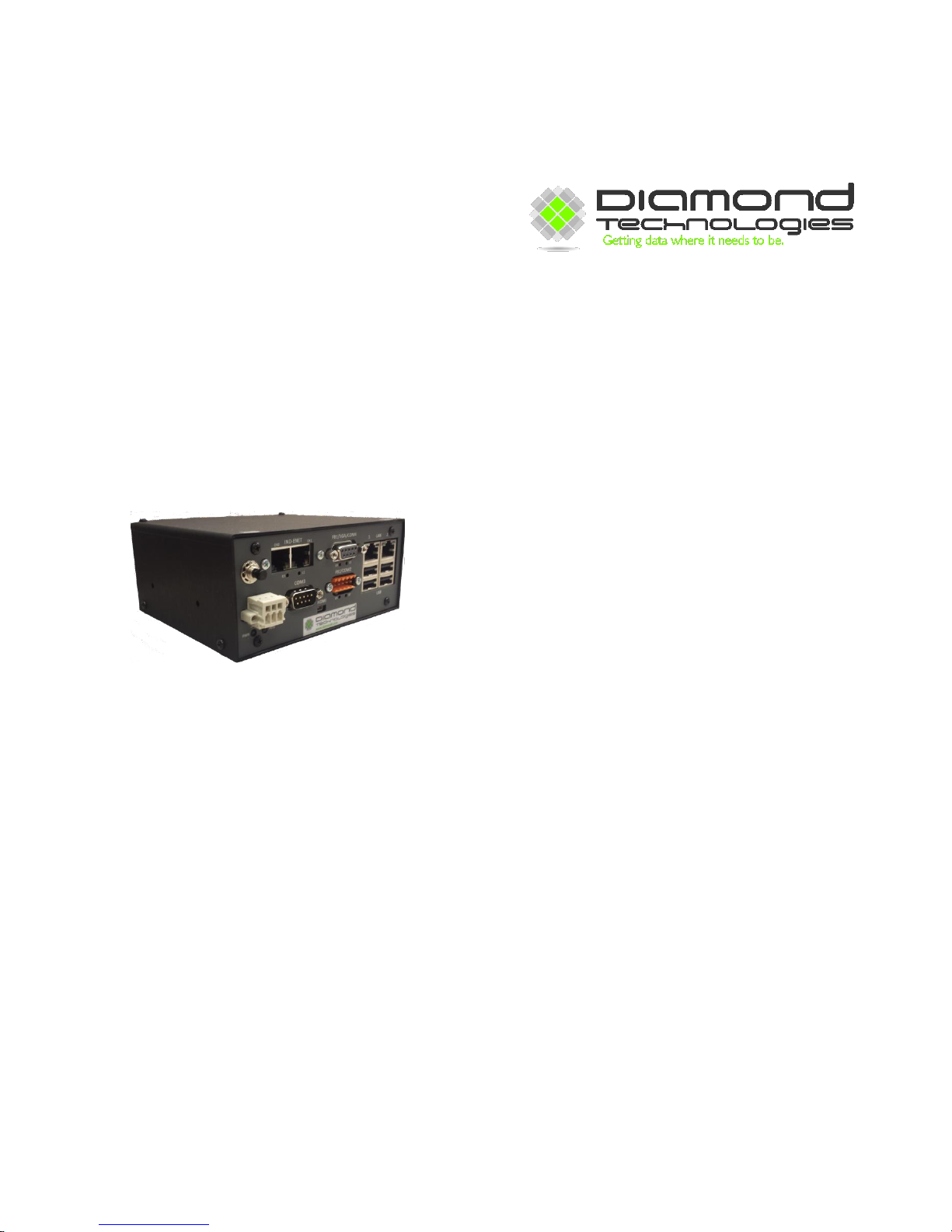
DT9000 Master
Quick Start Guide
V1.3
Page 2

6 Clock Tower Place
Suite 100
Maynard, MA 01754
USA
Tel: (866) 837-1931
Tel: (978) 461-1140
FAX: (978) 461-1146
http://www.diamondt.com/
Liability
Diamond Technologies Inc. shall not be liable for technical or editorial errors or omissions contained herein, nor for
incidental or consequential damages resulting from the use of this material. Those responsible for the use of this
device must ensure that all necessary steps have been taken to verify that the applications meet all performance
and safety requirements including any applicable laws, regulations, codes, and standards.
There are many applications of this product. The examples and illustrations in this document are included solely
for illustrative purposes. Because of the many variables and requirements associated with any particular
implementation, Diamond Technologies Inc. cannot assume responsibility for actual use based on these examples
and illustrations.
Diamond Technologies Inc., reserves the right to modify our products in line with our policy of continuous product
development. The information in this document is subject to change without notice and should not be considered
as a commitment by Diamond Technologies Inc.
Intellectual Property Rights
© 2014 Diamond Technologies Inc. * ALL RIGHTS RESERVED.* Protected to the fullest extent under
U.S. and international laws. Copying, or altering of this document is prohibited without express written consent
from Diamond Technologies Inc.
Diamond Technologies Inc. has intellectual property rights relating to technology embodied in the product
described in this document. These intellectual property rights may include patents and pending patent applications
in the US and other countries.
Diamond Technologies Inc. and the Diamond Technologies logo are trademarks of Diamond Technologies Inc. All
other trademarks are the property of their respective holders.
DT9000 Master: Quick Start Guide v 1.3 Page 2 of 27
Page 3
i Revision History
Version
Date
Description
1.0
11/2/2014
Original Version
1.1
12/29/2014
All Sections
1.2
3/26/2015
New Application Version (v1.2)
1.3
10/5/2015
New Application Version (v1.3)
ii Reference Documents
iii Table of Contents
..................................................................................................................................................................................................1
..................................................................................................................................................................................................2
i Revision History .....................................................................................................................................................................3
ii Reference Documents ............................................................................................................................................................3
iii Table of Contents .................................................................................................................................................................3
1.0 General ........................................................................................................................................................................4
1.1 Front View ..........................................................................................................................................................................4
1.2 Power ..................................................................................................................................................................................5
1.2 Industrial Ethernet Port .......................................................................................................................................................5
1.4 FB1/VGA/COM4 Port ........................................................................................................................................................5
1.5 FB2/COM2 Port .................................................................................................................................................................5
1.6 LAN Port ............................................................................................................................................................................5
1.7 COM Ports ..........................................................................................................................................................................6
1.8 HDMI Connector ................................................................................................................................................................6
2.0 Getting Connected .......................................................................................................................................................7
2.1 Troubleshooting Remote Desktop Connections .................................................................................................................8
2.1.1 Ensure that the DT9000 is on ......................................................................................................................................8
2.1.2 Ensure that you are connected to the proper LAN port ...............................................................................................9
2.1.3 Ensure that you have a direct connection to the device ..............................................................................................9
2.1.4 Ensure that your Ethernet port is being assigned a dynamic IP address .....................................................................9
3.0 Master Setup and Configuration ................................................................................................................................ 10
3.1 Master Devices and Firmware .......................................................................................................................................... 11
3.2 Master Configuration ........................................................................................................................................................ 11
4.0 Creating a Master Configuration ...................................................................................................................................... 12
4.1 Configuring a Modbus RTU Master ................................................................................................................................. 12
4.2 Configuring Network Masters with SYCON.NET .................................................................................................... 14
5.0 Network IO Monitor ......................................................................................................................................................... 19
5.1 Troubleshooting Network Data ........................................................................................................................................ 20
6.0 OPC Server ....................................................................................................................................................................... 21
DT9000 Master: Quick Start Guide v 1.3 Page 3 of 27
Page 4
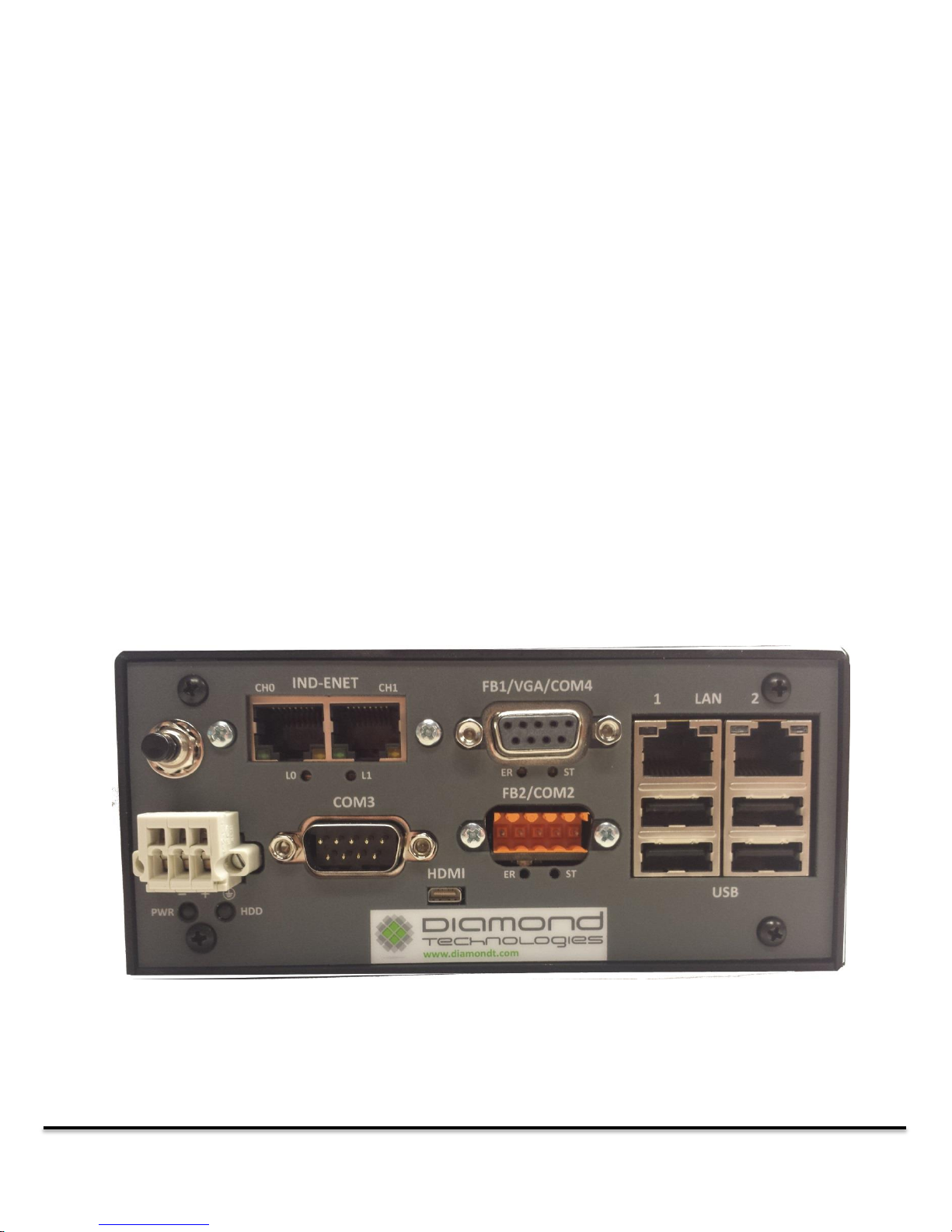
Front view of a DT9000 Master with Ethernet, Profibus and DeviceNet masters.
6.1 Tag Setup .......................................................................................................................................................................... 22
A1 IND-ENET and FieldBus LED Descriptions ............................................................................................................. 23
A1.0 Etherernet Connector ................................................................................................................. 24
Ethercat Firmware Installed ............................................................................................................................................... 24
Ethernet IP Firmware Installed .......................................................................................................................................... 24
Modbus TCP Firmware Installed ....................................................................................................................................... 25
Profinet IO Firmware Installed .......................................................................................................................................... 25
A1.1 ProfiBus Connector ..................................................................................................................... 26
A1.2 CANopen Connector ................................................................................................................... 26
A1.3 DeviceNet Connector .................................................................................................................. 27
1.0 General
The DT9000 Master features an Ethernet card which is able to act as a master for a number of different
Industrial Ethernet networks. The DT9000 Master can also optionally support other non-Ethernet based
industrial networks. This guide provides a general overview of the DT9000 setup and configuration for
use as an Ethernet master.
1.1 Front View
DT9000 Master: Quick Start Guide v 1.3 Page 4 of 27
Page 5

1.2 Power
Power (9-40V) is applied through the PWR connector on the bottom left of the front panel. When power
is properly applied to the device, the PWR LED will turn Yellow. If the reverse polarity is applied, the
HDD LED will turn red. If this occurs, disconnect the device from the power supply and switch the
positive and negative wires in the connector. Once the power is properly connected, the push button
switch directly above the PWR connector can be used to turn the DT9000 on.
1.2 Industrial Ethernet Port
The IND-ENET port is used to connect the Ethernet master to the industrial network. Depending on
which network master you have configured in the Master Console Application, the two connectors can
have different functions. In general (especially with a single, non-looping connection) you should use the
Channel 0 (left socket). See Appendix A1 for information on network specific LED functions.
1.4 FB1/VGA/COM4 Port
Depending on the options your DT9000 Master has installed, this port will have a different function.
If you have at least one FieldBus master installed (DeviceNet, ProfiBus, CANopen) this port will house
the connector for one of your FieldBuses. Consult the product description for your DT9000 device part
number for information about which FieldBus adapter is on which port.
If you do not have a FieldBus master (Ethernet Only) this port will be either a VGA connection to the
DT9000 or COM4 (see 1.7 COM Ports). The VGA connection allows you to connect the DT9000 to a
monitor instead of controlling it through remote desktop (also see 1.8 HDMI Connector).
1.5 FB2/COM2 Port
Depending on the options your DT9000 Master has installed, this port will have a different function.
If you have two FieldBus masters installed (DeviceNet, ProfiBus, CANopen) this port will house the
connector for one of your FieldBuses. Consult the product description for your DT9000 device part
number for information about which FieldBus adapter is on which port.
If you have fewer than two FieldBus master options installed, this port will be COM2 (see 1.7 COM
Ports).
1.6 LAN Port
The LAN ports can be used to connect the DT9000 to a local network. Initially, the LAN2 port is used to
directly connect a PC to the DT9000 to configure and control the device. Both LAN ports can be
configured as desired once the initial connection is made, but changing the default settings on LAN2 is
not recommended, as it could prevent you from connecting to the DT9000. Also the LAN1 port is
DT9000 Master: Quick Start Guide v 1.3 Page 5 of 27
Page 6
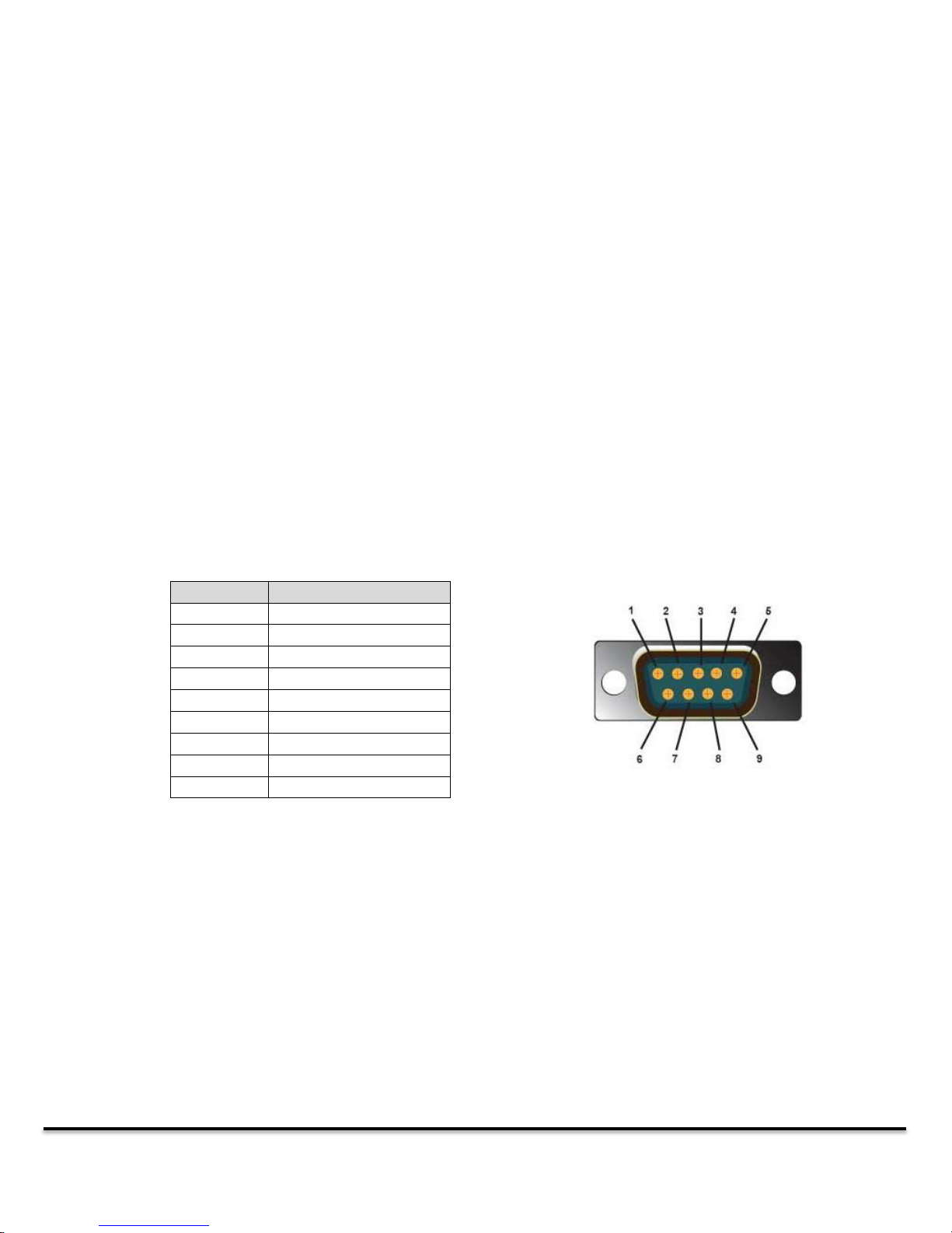
PIN
Connection
1
422 Rx+
2
232 Rx
3
232 Tx
4
NC or +5 VDC out *
5
GND
6
422 Rx-
7
NC 8 422 Tx+ / 485 D+
9
422 Tx- / 485 D-
initially setup as a pass through network port. This allows the user to connect a corporate network to
the LAN1 port and devices connected to LAN2 will have a connection to both the DT9000 and the
corporate network.
1.7 COM Ports
Depending on how many network masters are installed in the DT9000, there will be either 1 to 3 COM
ports available. These ports are used by the Modbus RTU Master and can be configured as a generic
serial port to attach other serial devices to the DT9000.
These COM ports support RS232, RS422 and RS485 serial protocols. The protocol is determined by the
connection made. Because of this it is recommended that the cables used to connect serial devices to
the DT9000 only connect the pins required for the desired protocol. When using a standard serial cable,
active signals on pins used by the DT9000 for different protocols could cause it to switch communication
methods and not work as desired. Cables for all supported protocols are available from the Diamond
Technologies.
COM 2, COM3 – Supports RS232/RS422/RS485.
* +5 VDC out on pin 4 is enabled by installing internal jumper
J34 – COM2
J35 – COM3
1.8 HDMI Connector
Though the preferred method for connecting to the DT9000 is using Windows Remote Desktop (see 2.0
Getting Connected) you also have the option to connect the DT9000 to a screen using the mini HDMI
connector and controlling it as you would a desktop computer (with USB mouse and Keyboard).
DT9000 Master: Quick Start Guide v 1.3 Page 6 of 27
Page 7
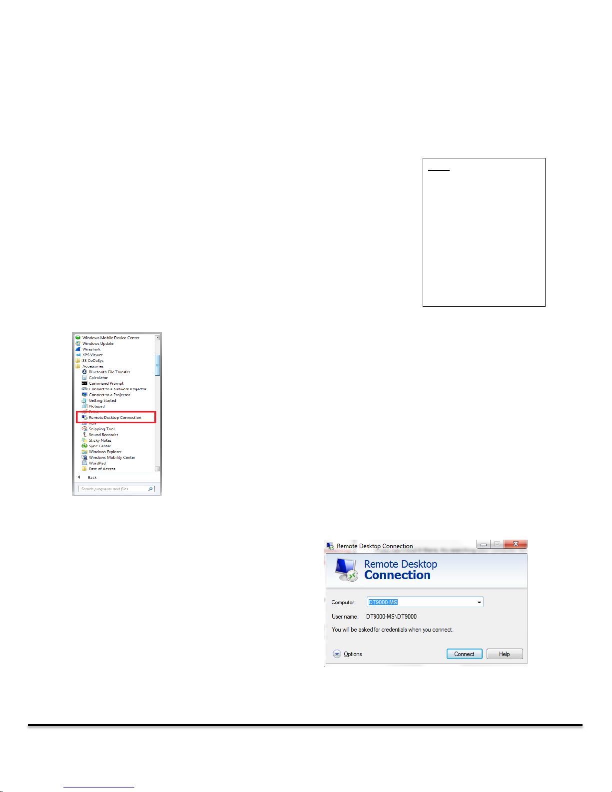
The preferred method of connecting to the DT9000 Master is using Windows
Remote Desktop. Before initiating the connection:
1. Ensure that your PC’s network adapter is set to receive an IP address
via DHCP.
2. Make sure that LAN 2 on the DT9000 is connected to an Ethernet
port on your PC through a standard Ethernet cable. The DT9000 will
automatically assign an IP address to your network adapter when
you connect to it.
Note: The VGA and
HDMI Ports can also be
used to access the
DT9000. If you hook up a
monitor, mouse and
keyboard the DT9000
can be used like any
desktop PC.
The Remote desktop tool can typically be found under “Start >
Accessories > Remote Desktop Connection”
If you can’t find it there, try searching your computer for it. Most
Windows installations will come with the Remote Desktop tool.
When you start Remote Desktop, it will ask for the
name of the computer you would like to connect
to. You can either enter the name or IP address of
the DT9000 to connect. The default name is
DT9000-MS. The default IP address is
192.168.137.1.
2.0 Getting Connected
DT9000 Master: Quick Start Guide v 1.3 Page 7 of 27
Page 8
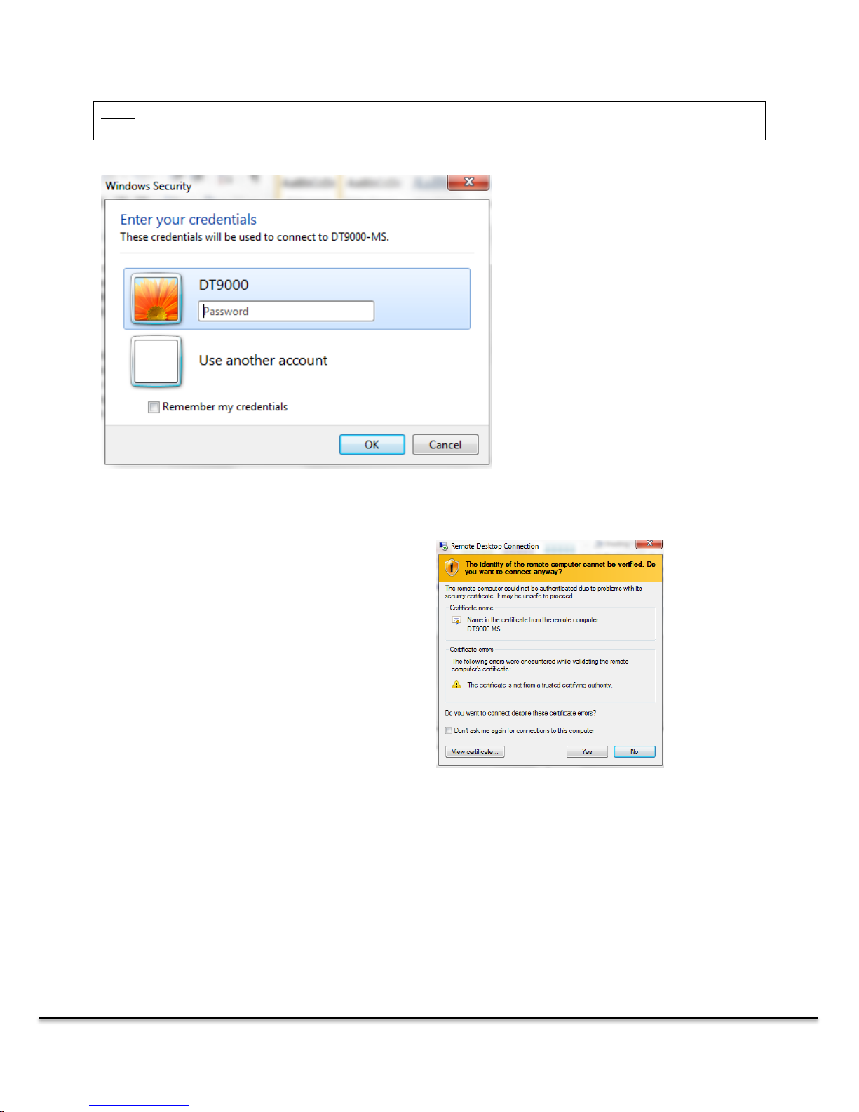
Note: Depending on how your Network Discovery is configured, your pc may not be able to connect using
the computer name. In this case, use the IP address.
If you are able to successfully connect
with the name or address you provided,
you will be prompted to enter your
account password. The username is
DT9000 and the password is Diamond
Depending on your computers security settings,
you may see a warning similar to this one when
the Remote Desktop connection is being
established.
Click yes to continue with the connection.
You should now be remotely connected to your DT9000. If you get an error while attempting to connect,
please read the Troubleshooting Remote Desktop Connections section of this guide.
2.1 Troubleshooting Remote Desktop Connections
2.1.1 Ensure that the DT9000 is on
First, check that the PWR LED is solid green. If the LED shows Yellow, the device is in “Standby Mode.” If
this is the case, push the button above the PWR connector to turn the DT9000 on. Wait a few minutes
DT9000 Master: Quick Start Guide v 1.3 Page 8 of 27
Page 9

To access these settings, first
Navigate to “Start > Control Panel >
Network and Sharing Center”
Click the “Local Area Connection” link for the
network adapter that is connected to the DT9000.
Note: If you have more than one Local Area
Connection, ensure that you are selecting the
correct one. You may have to have the network
cable connected for this option to appear.
for it to boot up and attempt to connect again. If the HDD LED (below the PWR connector) is solid red,
this means the power is not properly connected (see section 1.2).
2.1.2 Ensure that you are connected to the proper LAN port
To make the initial remote desktop connection to your device, you must be using LAN2 on the DT9000.
LAN 1 can later be configured to allow a remote desktop connection if you wish, but the initial device
setup will only allow the connection to be made on the LAN2 port. If the cable is connected properly,
you should see the green and yellow LEDs above the LAN2 port active.
2.1.3 Ensure that you have a direct connection to the device
DO NOT try to connect to the DT9000 through a router or switch when you make the initial Remote
Desktop connection. The DT9000 should be plugged directly into an Ethernet port on the PC you wish to
connect from. After making the initial connection you can configure the network settings to allow for
different types of connections.
2.1.4 Ensure that your Ethernet port is being assigned a dynamic IP address
If your PC is set to a static IP address or static DNS server, you will be unable to connect to the DT9000
using Remote Desktop.
DT9000 Master: Quick Start Guide v 1.3 Page 9 of 27
Page 10
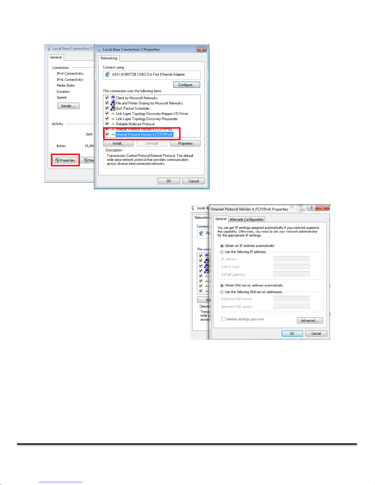
Clicking the “Properties” button will
bring up the “Local Area Connection
Properties” window. Scroll down until
you see Internet Protocol Version 4
(TCP/IPv4). Select that option and click
“Properties”
Set up your network connection so that it is the
same as the window pictured to the right.
Ensure that “Obtain IP address automatically” is
selected
Ensure that “Obtain DNS server address
automatically” is selected
3.0 Master Setup and Configuration
The DT9000 can be configured as a master on many different industrial networks, depending on the
options installed. To configure these networks, open the DT9000 Master Console application. This tool
can be found under C:\Program Files\Diamond Technologies Inc\DT9000 Master Console and can also be
found as an icon on your DT9000 desktop. The DT9000 Master Console must be run as an Administrator
to function properly.
DT9000 Master: Quick Start Guide v 1.3 Page 10 of 27
Page 11
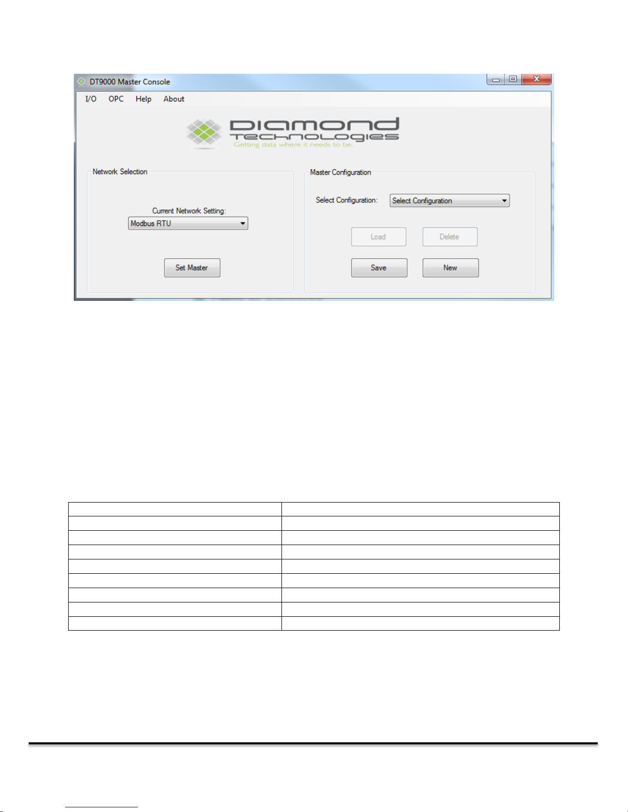
The master console can be used to select and configure Master communication channels
Network Firmware
Hardware Option
EthernetIP Master
Ethernet Adapter
EtherCAT Master
Ethernet Adapter
Profinet I/O Master
Ethernet Adapter
Profibus Master
PROFIBUS Adapter
Profibus DPV2 Master
PROFIBUS Adapter
CANopen Master
CANopen Adapter
DeviceNet Master
DeviceNet Adapter
Modbus RTU Master
Serial COM Port
3.1 Master Devices and Firmware
The Network Selection section of the application can be used to change the firmware on the physical
communication channels in the DT9000.
To change the firmware, select the firmware you would like to install and click Set Master. If the
firmware is successfully loaded the communication channel will be initialized with the new protocol
stack and a success message will appear.
The firmware you are loading must be compatible with the physical hardware connected to the
communication channel. Below is a list of hardware options and available network firmware.
3.2 Master Configuration
Once Firmware is downloaded to the device the next step is to build a Master Configuration. The
Master Configuration defines what slave devices the Master will communicate with, the specifics about
DT9000 Master: Quick Start Guide v 1.3 Page 11 of 27
Page 12
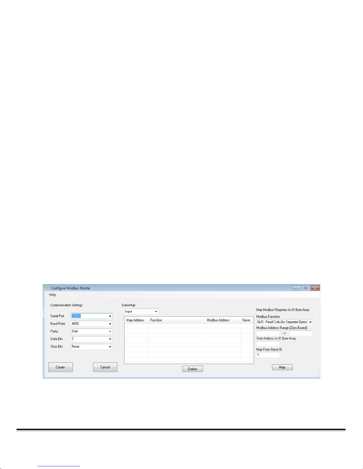
The configuration screen for the Modbus RTU Master Device
each slave, as well the specifics about the network communications. (See Section 4.0 for more
information about creating a new configuration file.)
The Master Configuration section can be used to switch between commonly used master
configurations. It allows you to save and load device configurations with a single click. When you select a
device, the Select Configuration selection box will display all saved configurations for the currently
loaded firmware. Loading a new firmware to the device will refresh this list. Note that the configuration
displayed in the box is not necessarily the currently loaded configuration.
To save the currently downloaded configuration simply click the Save button. This will open a dialog
window asking you to name the configuration. If the configuration is successfully saved, a success popup
window will appear.
To load a configuration to the device, select the configuration you wish to load from the Select
Configuration selection box and click the Load button. If the master configuration is successfully loaded
the communication device will be restarted and a success popup window will appear. This operation will
overwrite any existing configuration in the device.
The Delete button will delete the currently selected configuration file. This operation cannot be undone.
4.0 Creating a Master Configuration
Depending on which communication device you have selected, the “New” button will either open a
configuration creation form, or start a second application to assist with configuring the master for
network communication.
4.1 Configuring a Modbus RTU Master
Before you can see the Network IO data from your Modbus RTU Master device, you must configure
some basic communication parameters and map the Modbus data to the Network IO Array.
DT9000 Master: Quick Start Guide v 1.3 Page 12 of 27
Page 13
Note: When mapping Coils or Discrete Inputs, there are two options for each read and write function.
You can map them as ‘bytes’ or as ‘bits.’
Mapping them as bytes means that each Coil will be mapped to a byte in the Network IO Array. This is
useful for viewing flags. Any output mapped with this option will set a 1 for any entered value above 0.
Mapping them as bits means that all of the coils in your map will be read and packed into a byte (8 bits).
If the number of coils mapped are not a multiple of 8, the high bits of the last byte will be padded with
zeros. This option is useful for viewing larger data fields stored in the Modbus Coils (integers, etc.).
Note: No two data maps can intersect each other in the Input and Output Network IO Arrays. If you
attempt to add a Data Map that conflicts with an existing mapping, you will get an error.
The communication settings allow you to select the Serial Port that the Master will use to communicate,
as well as some basic serial parameters. Ensure that the parameters here reflect the settings and
capabilities of your slave device(s). The Serial Port numbers are labeled on the front of the DT9000. All
listed serial ports may not be available, depending on your DT9000s installed hardware options.
The Data Map section allows you to associate any Modbus coil, input or register with a section of the
Network IO Array for both inputs and outputs. The dropdown menu at the top allows you to select
between the “Input” and “Output” data mappings. Depending on your selection, the list below will
display all input or output maps already defined.
The fields on the right of the screen allow you to create a new data mapping. “Modbus Function” box
will show either read or write functions depending if you have “Input” or “Output” data selected. This is
the Modbus function that will be used to read or write your data from the slave.
The fields labeled “Modbus Address Range” indicate the Modbus address to perform the operation at
on the slave device. Entering an invalid address could cause errors when viewing the Network IO. Note
that the addresses are absolute (zero based) and are inclusive. This means that if you read addresses 0
through 5 you are reading 6 registers.
Next, enter the starting byte address in the Network IO array you want to map the data to. The ending
address and data length will be calculated based on the Modbus function and Modbus address range
you have selected and displayed in the data map list to the left.
Once you have completed your configuration hit the “Create” button on the bottom left. This will
automatically load your new configuration into the Modbus RTU Master. Be sure to save the
configuration if you wish to keep it!
DT9000 Master: Quick Start Guide v 1.3 Page 13 of 27
Page 14
Username
Administrator
Password
[blank]
4.2 Configuring Network Masters with SYCON.NET
Some of the network devices must be configured using a second program called SYCON.NET. When you
hit the “New” button with one of these masters selected, SYCON.NET will automatically open.
When SYCON.NET is opening, it will ask for a username and password. The default is:
For most of the network types, you will be required to upload a datasheet to Sycon.net for each type of
slave device that will be included in the network configuration. The exact file format and content for this
datasheet is network specific and vendor specific, and it should be available from the slave device
manufacturer.
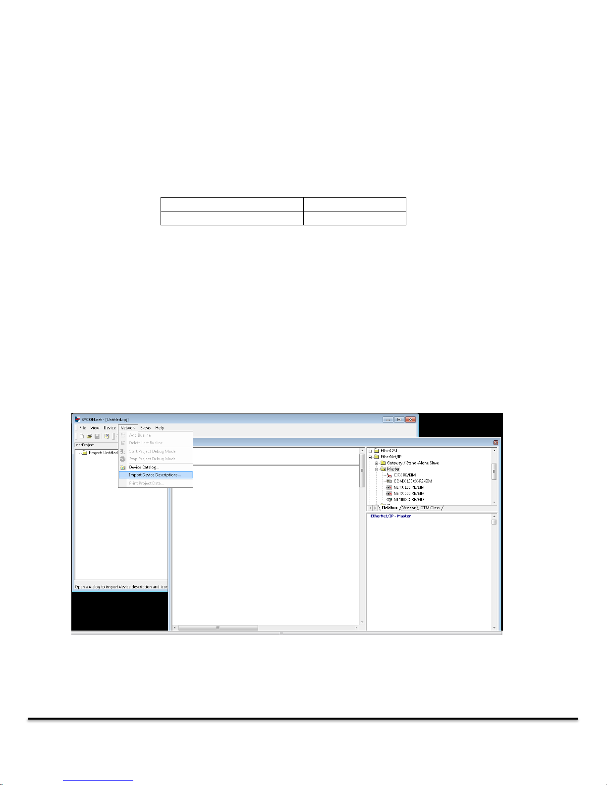
To add a datasheet simply select the Network drop down list in SYCON.NET and then click on Import
Device Descriptions. This will allow you to select the specific slave configuration file. To do this first
select the correct file type in the Files of Type box, next navigate to and select the specific configuration
you would like to import. Note that you can easily drag and drop the Device Description files from your
PC onto the DT9000 using Windows File Explorer or transfer them via a USB disk.
After you have imported your device description file(s) your devices will show up in the available devices
list in the NetDevice window on the right side of the SYCON.NET screen. You will need to look under
DT9000 Master: Quick Start Guide v 1.3 Page 14 of 27
Page 15
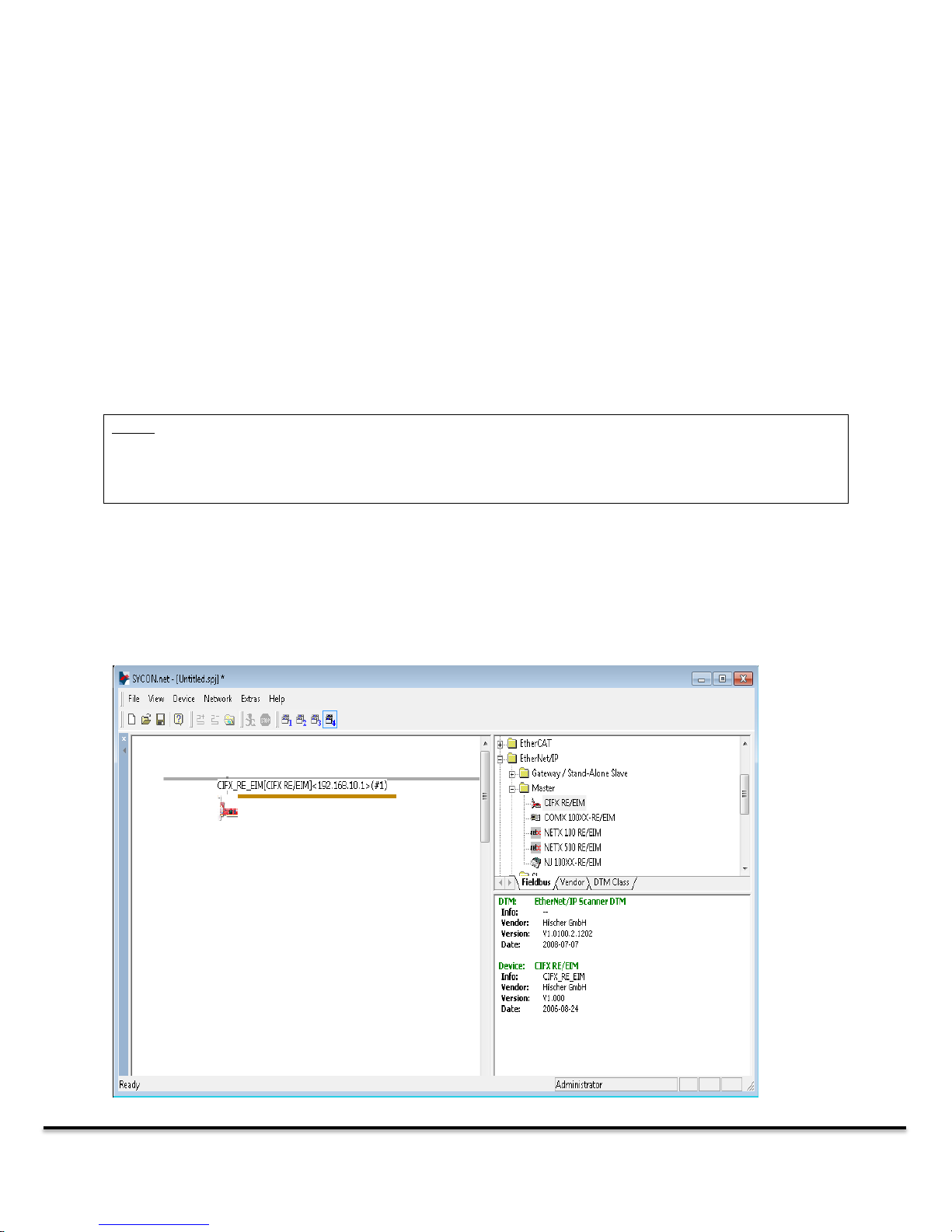
Note: The screenshots in this section show the configuration of an Ethernet IP master and slave.
Depending on the network, the screens may look slightly different, but the basic procedure for
configuration will be the same.
Drag and drop device descriptors from the catalog on the right into the Network window. Note that
your cursor must be on the network (grey bar) to be able to drop the master into the configuration.
the specific network and then the specific type of device you have, for example Profibus and then Slave
to locate a Profibus Slave device description. If the device did not show up you may have to restart
SYCON.NET.
Once you have loaded all your slave devices into the SYCON.NET catalog, you can begin to build your
configuration. Start by finding the folder on the right hand side of the NetDevice window that
corresponds with the industrial network you have configured on your network card. Find the Network
Master device in that folder and drag it into the blank area to the left (see image below, The DT9000
utilizes the CIFX RE/EIM modules for Ethernet networks).
DT9000 Master: Quick Start Guide v 1.3 Page 15 of 27
Page 16
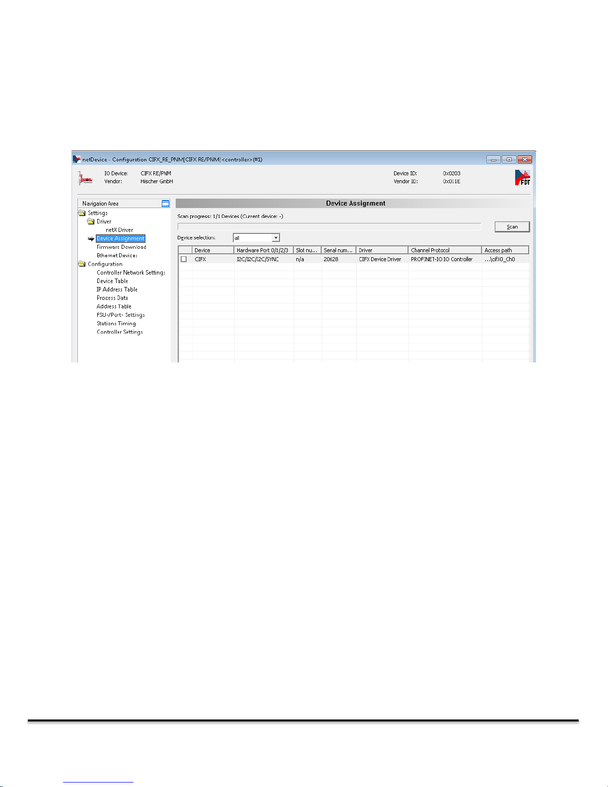
Next, we have to assign the device descriptor you have just selected to your actual network hardware.
Right-click on the master in the network window and select “Configuration…”
In the “Navigation Area” on the left of the configuration window, find “Device Assignment.” Set the
Device Selection pull-down menu (to the right) to “all” and hit the Scan button. If your network
firmware was properly installed, you should see the card come up in the list. Check the box next to the
network card that represents the network master you are looking to utilize and click Apply at the
bottom of the screen then select OK. The Channel Protocol column will show the firmware of each card
installed in your DT9000. If the Channel Protocol section does not indicate the protocol you are
attempting to use this means you have the wrong device firmware loaded (see section 3.1).
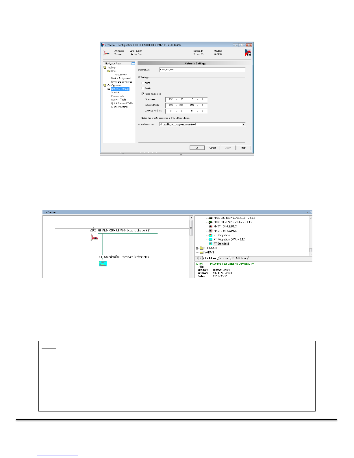
Next, you can use the options in the NetDevice Window to set other parameters specific to your
network. In the case of Ethernet IP you will need to set your IP address as well as subnet mask as shown
below.
DT9000 Master: Quick Start Guide v 1.3 Page 16 of 27
Page 17
Note:
If the Datasheet you imported came directly from the device manufacturer (usually means it will contain
the exact name of the device in it) then you may not have to do any configuration in the slave
configuration window.
There are some situations when a manufacturer will provide you with the datasheet for the 3rd party
hardware they use for network integration, so it does not contain the specific I/O configuration of the
device. If this is the case, the device manufacturer will need to provide additional instruction on how the
slave device is configured so you can set it up with your master.
Once the Master is setup you can setup your network slave devices. Drag any slave devices that you
want to connect to the Master from the catalog into the network window so they attach to the network
coming out of the master (see image below).
Right-click on the slave device in the network window and select “Configuration…” This will bring up the
slave configuration window. This window is going to be slightly different depending on the type of
network you are using. You need to set up the slave configuration so the master knows exactly what
data is being communicated over the network by the slave (input and output size, for example).
DT9000 Master: Quick Start Guide v 1.3 Page 17 of 27
Page 18
Note: Make sure to save the generated configuration file in the DT9000 Master application. If you wish
to edit the configuration in the future, make sure that you also save the SYCON.net project.
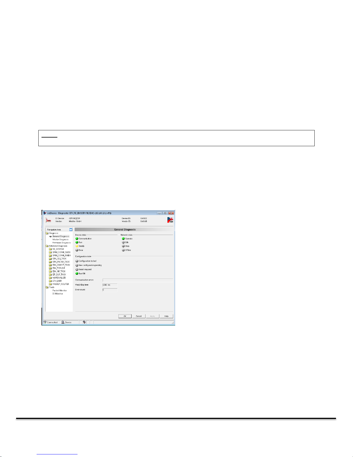
This “General Diagnosis” screen is
indicating that there are no errors on
the network and the network is in a run
state.
Once you have completed the configuration for all of your slave devices, you need to send the
configuration to the network master. Right-click on the master icon in the network window and select
“Download.” Once the download is complete communication should automatically start between the
master and the slaves.
Be sure to download the configuration every time you make a change. The changes in SYCON.NET will
not be reflected in the actual master hardware until you download the configuration. This new
configuration will now be accessible through the DT9000 Master Console application.
After downloading the configuration you can view the status of the network and troubleshoot any
communication issues, right click on the master icon in the network window and click “Diagnostic…”
This will bring up the master configuration menu. To access the “General Diagnosis” and “Master
Diagnosis” select them from the navigation area on the left.
DT9000 Master: Quick Start Guide v 1.3 Page 18 of 27
Page 19
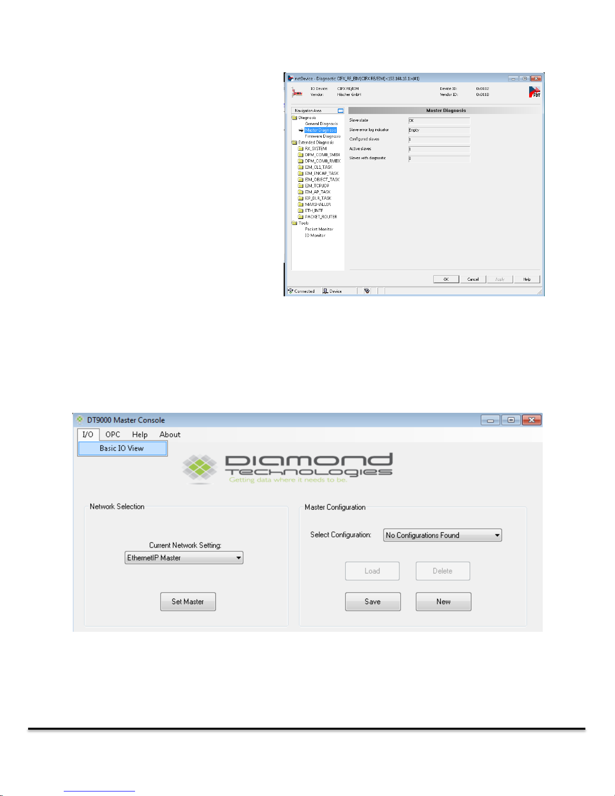
The “Master Diagnosis” tab can also give
some useful information about the current
state of the network. This screen is showing
the number of configured slaves and their
status.
To view the network IO data you must first select a device and a configuration. Once the configuration
has been loaded you can select the “Basic IO View” from the I/O Menu Item.
5.0 Network IO Monitor
DT9000 Master: Quick Start Guide v 1.3 Page 19 of 27
Page 20
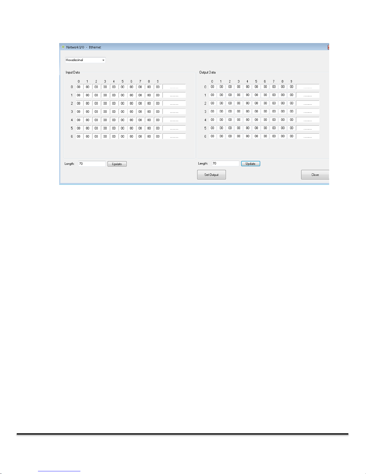
The network IO Monitor displays the real-time input and output data over the selected network. Each
row of data contains 10 bytes, and the ASCII value of that row is displayed next to it, with a ‘.’
symbolizing an unprintable character. The dropdown menu at the top allows you to switch between
hexadecimal and decimal data.
To write to the output data, simply enter the values you wish to write into the corresponding bytes in
the output array and hit “set output.” You will get a popup confirmation if the write was successful.
5.1 Troubleshooting Network Data
Many Industrial Networks will not show any of the data if there is an error in the configuration. If you
are seeing all zeros on your IO window, review the configuration file and ensure that it is correct.
Other networks (Such as Modbus RTU) are able to display some of the mapped data when a minor
configuration error is present. The network IO Monitor will pop up an error to indicate the mappings
that are not correct, and those bytes will change red on the IO Screen. Any other data mappings will
continue to function, though for large data maps, these errors could cause a significant slowdown in
communication between master and slaves.
DT9000 Master: Quick Start Guide v 1.3 Page 20 of 27
Page 21
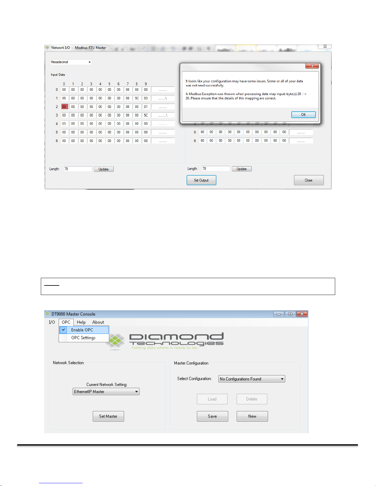
Here is an example with one byte of incorrectly mapped data. Only the affected byte(s) will turn red and
the rest of the data will be read as usual.
Note: OPC functionality is an optional feature. If you have not yet purchased OPC functionality, the OPC
menu will be disabled in your application.
6.0 OPC Server
The DT9000 can be set up as an OPC server, allowing you to set and read data through the OPC protocol.
You can enable the OPC server functionality using the OPC dropdown menu at the top of the
application.
DT9000 Master: Quick Start Guide v 1.3 Page 21 of 27
Page 22
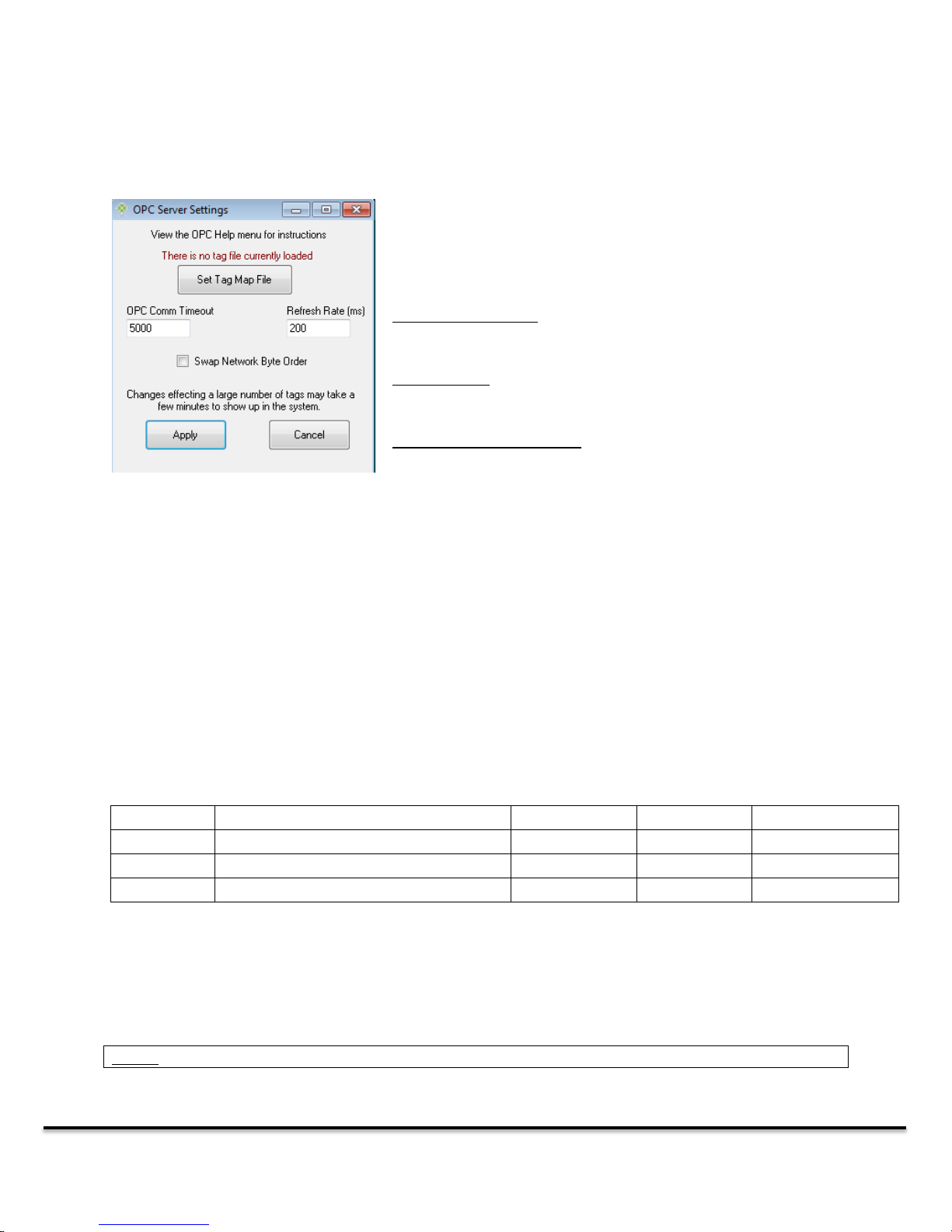
Clicking the OPC Settings option in the OPC menu will open the
OPC configuration window. Use the Set Tag Map File button to
add a new tag mapping CSV file. This will overwrite the
currently configured OPC tags.
OPC Comm Timeout: The time the DT9000 will wait before
timing out its connection with the OPC server.
Refresh Rate: The frequency that the Network Data is refreshed
to the OPC server.
Swap Network Byte Order: Swaps the byte order (Big Endian /
Little Endian) used to create the OPC data types for the tags.
~TagGroup
Tag Name
Tag Type
Data Offset
Transfer Type
GroupName
Alarm_Flag
UByte
0
Output
GroupName
System_Status
UShort
1
Output
GroupName
Run_Speed
Integer
3
Input
Note: Any line beginning with a ~ character will be treated as a comment and will be ignored.
To set up OPC server functionality, you must map your network byte data to OPC tags. This is done
through a CSV file which allows you to define tag names, tag types and byte boundaries (see 6.1 Tag
Setup).
When OPC is enabled, it will effectively disable the Output functionality on your I/O Monitor. This is
because the network output will be based on the value of any mapped OPC tags, and not the value
entered in the I/O Monitor. The I/O Monitor will still show the network inputs. Disabling OPC will simply
break the link between the industrial network and the OPC tags, so the tags will still exist but they will
no longer be updated based on the network inputs.
6.1 Tag Setup
The OPC tags are created using a CSV File. To create the file you can simply open an Excel spreadsheet (
or any CSV compatible editor) program and enter the tag information in the following format:
When you are finished, export the file as a CSV and save it to your DT9000. You may also just create the
CSV file manually, separating each column with a comma:
GroupName,TagName,UByte,0,Output
DT9000 Master: Quick Start Guide v 1.3 Page 22 of 27
Page 23
Byte
8 bits, signed
UByte
8 bits, unsigned
Short
16 bits, signed
UShort
16 bits, unsigned
Integer
32 bits, signed
UInteger
32 bits, unsigned
There are currently 6 supported OPC data types:
The master input and output byte arrays are separate, so the input mapping and output mapping will
both start at data offset zero. Be careful you do not unintentionally overlap bytes when defining your
tags. This IS allowed and will not produce an error but you will likely get unintended results in your OPC
values.
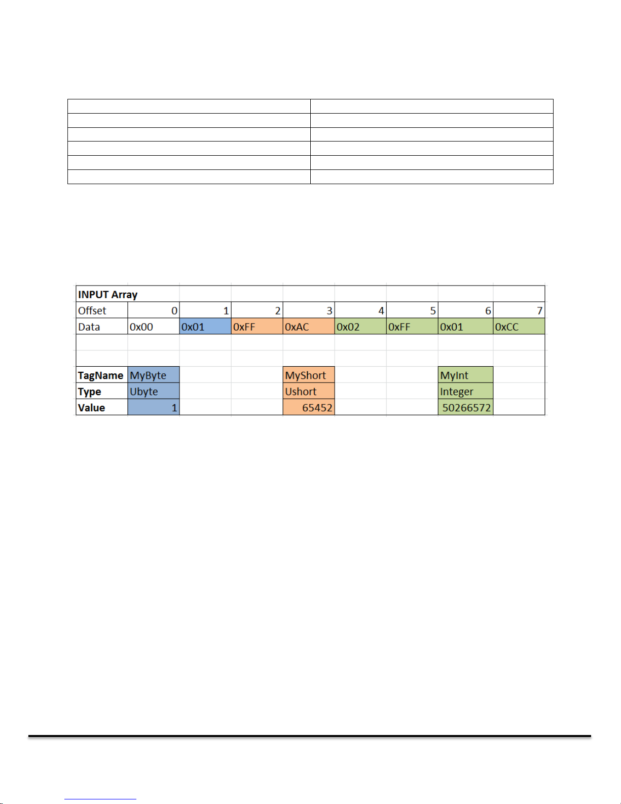
The above image illustrates a simple example as to how the data is mapped between OPC tags and the
Input/Output byte arrays on the network master. Bytes can be mapped in any order and mappings can
overlap if required. The datatype defined determines the number of bytes in the mapping, you simply
need to give the offset of the starting byte. The above mapping would be defined with three lines in the
CSV File:
TagGroup,MyByte,UByte,1,Input
TagGroup,MyShort,UShort,2,Input
TagGroup,MyInt,Integer,4,Input
A1 IND-ENET and FieldBus LED Descriptions
This appendix provides descriptions of the LED indicators on the DT9000 Fieldbus connectors. The LEDs
have different meanings depending on the network firmware installed.
DT9000 Master: Quick Start Guide v 1.3 Page 23 of 27
Page 24
CH0
CH1
Green
Ethernet Link
Yellow
Ethernet Activity
Green
N/A
Yellow
N/A
L0
Color
State
Description
Off
Off
Device is in the INIT state.
Green
Flashing (2.5 Hz)
Device is in the PREOPERATIONAL state
Green
Flashing (10Hz)
Device is in BOOT state
Green
Single Flash
Device is in SAFE-OPERATIONAL state
Green
On
Device is in OPERATIONAL state
L1
Color
State
Description
Off
Off
Master has no errors
Red
On
Communicator error. Read error code from Dual-Port
Memory.
CH0
CH1
Green
Ethernet LINK
Yellow
Ethernet ACT
Green
Ethernet LINK
Yellow
Ethernet ACT
L0
Color
State
Description
Green
On
Device is operational
Green
Flashing 1Hz
Standby Mode, No configuration loaded
Red/Green
Flashing 1Hz
Self-Test on power up
Red
Flashing 1Hz
Minor Fault, (incorrect configuration can be considered
minor fault)
Red
On
Major Fault, device cannot recover
Off
Off
No power to device
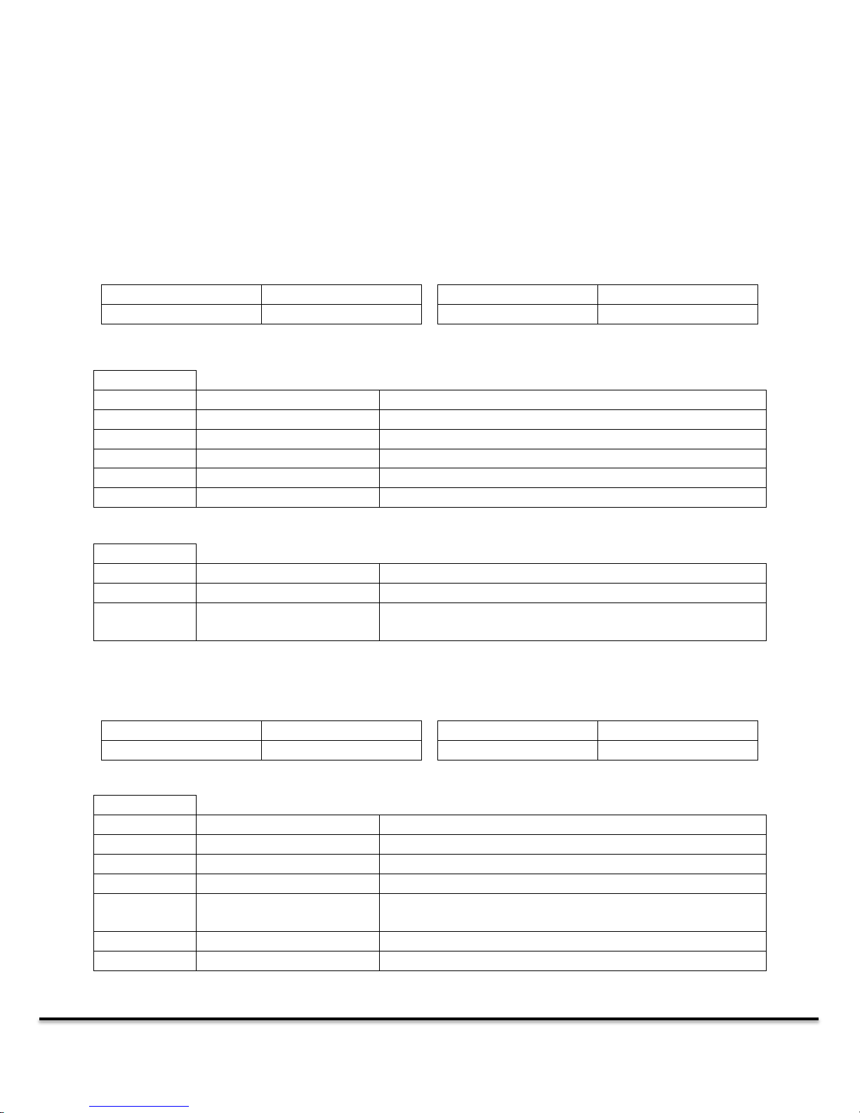
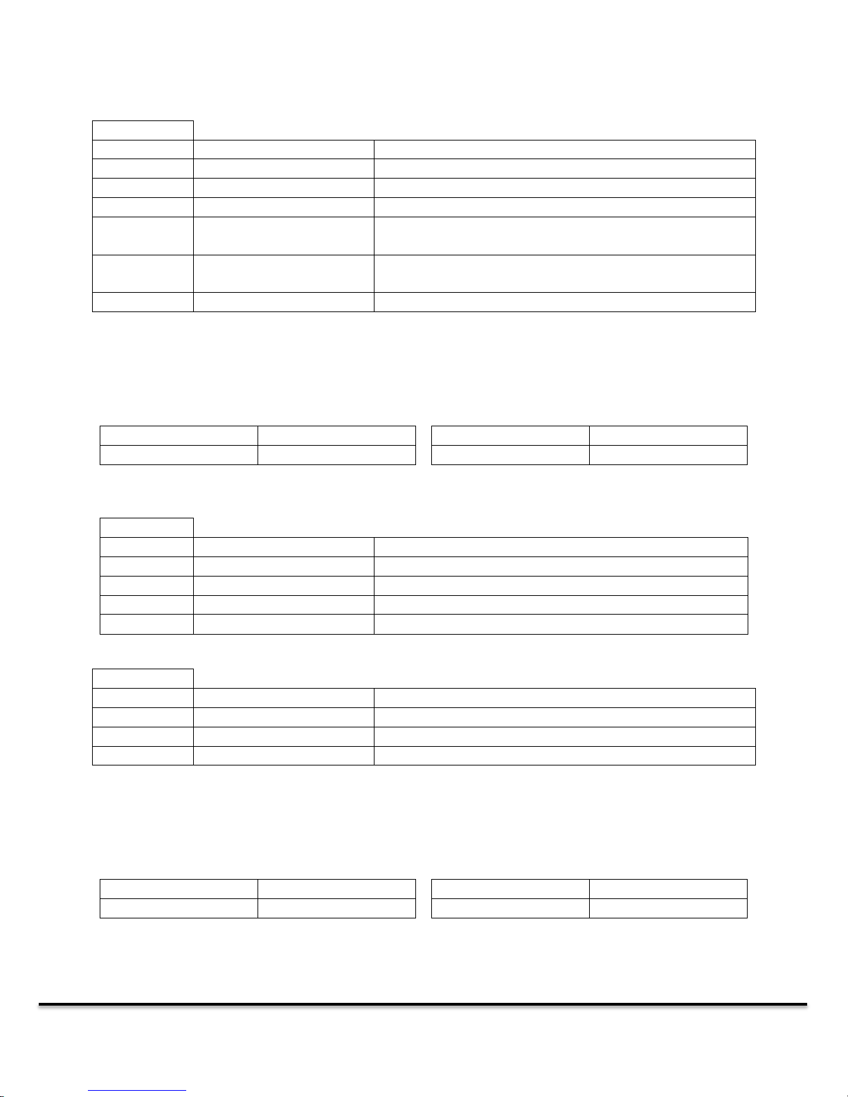
A1.0 Etherernet Connector
There are 6 LEDs on the Ethernet Connector. Two standard Ethernet LEDs for each Ethernet port (green
on the left and yellow on the right) and two status LEDs below the Ethernet connector. The left LED is
referred to as L0 and the right L1.
Ethercat Firmware Installed
Ethernet IP Firmware Installed
DT9000 Master: Quick Start Guide v 1.3 Page 24 of 27
Page 25
L1
Color
State
Description
Green
On
Device has established at least one connection
Green
Flashing 1Hz
Device has IP address, but no established connection
Red/Green
Flashing 1Hz
Self-Test on power up
Red
Flashing 1Hz
Connection timeout, status will persist until connections
are re-established.
Red
On
Device detected that another device on the network is
using the same IP address
Off
Off
No power to device OR device does not have an IP address
CH0
CH1
Green
Ethernet LINK
Yellow
Ethernet ACT
Green
Ethernet LINK
Yellow
Ethernet ACT
L0
Color
Status
Description
Green
On
Connected to at least one device
Green
Flashing 1Hz
Ready, no configuration loaded
Green
Flashing 5Hz
Configured, waiting for communication
Off
Off
Not ready
L1
Color
Status
Description
Off
Off
No Communication Errors
Red
Flashing 2Hz
System Error
Red
On
Communication Error
CH0
CH1
Green
Ethernet LINK
Yellow
Ethernet ACT
Green
Ethernet LINK
Yellow
Ethernet ACT
Modbus TCP Firmware Installed
Profinet IO Firmware Installed
DT9000 Master: Quick Start Guide v 1.3 Page 25 of 27
Page 26
L0
Color
Status
Description
Off
Off
No Errors
Red
Flashing 1Hz, 3 sec
DCP signal service initiated by the bus
Red
Flashing 2Hz
Invalid configuration, Watchdog error or Internal error
L1
Color
Status
Description
Off
Off
No Errors
Red
Flashing 2Hz
Configuration fault: not all configured devices are
connected
Red
On (With L0 On)
No Valid Master License
Red
On (With L1 not On)
No Ethernet link
ST
Color
State
Description
Green
Solid
Communication to all slaves established
Green
Flashing at 5 Hz
Configured, but no bus communication
Green
Flashing irregular
No configuration / Incorrect configuration
Green
Off
ERROR (see Error LED) or no power to device
ER
Color
State
Description
Red
Off
No ERROR / no power to device
Red
Flashing at 5 Hz
No communication with at least one slave device
Red
Solid
No communication to all slaves or serious bus error
occurred
ST
Color
State
Description
Green
Solid
Device is in OPERATIONAL state
Green
Flashing at 2.5 Hz
Device is in PREOPERATIONAL state
Green
Single Flash
Device is in STOPPED state
Green
Off
ERROR (see Error indicator) OR device is executing a reset
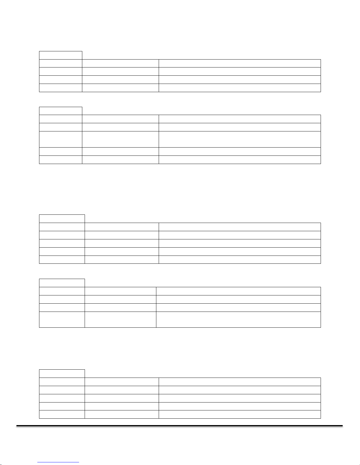
A1.1 ProfiBus Connector
The ProfiBus connector has two LEDS directly below it. The one on the left is the Error (Er) indicator and
the one on the right is the Status (ST) indicator.
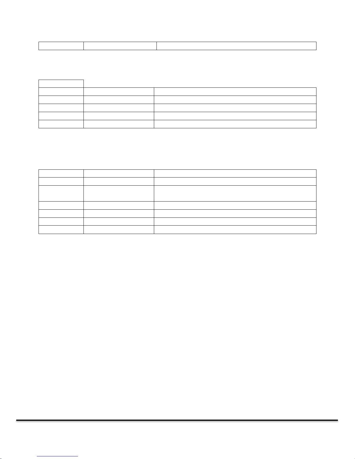
A1.2 CANopen Connector
The CANopen connector has two LEDs directly below it. The one on the left is the Error (Er) indicator and
the one on the right is the Status (ST) indicator.
DT9000 Master: Quick Start Guide v 1.3 Page 26 of 27
Page 27
OR device has no configuration loaded
ER
Color
State
Description
Red
Off
No ERRORs
Red
Single Flash
WARNING limit reached (too many error frames)
Red
Double Flash
Error Control Event Occurred (NMT slave or NMT Master)
Red
Solid
The device is in BUS OFF state
Color
State
Description
Green
On
Online, Connection established with all slaves
Green
Flashing 1Hz
Online, no connection established (missing or incorrect
configuration)
G-> R -> OFF
Flashing 2Hz
Self-test after power on.
Red
Flashing 1Hz
Minor Fault / Connection Timeout / No Network Power
Red
On
Critical fault / Link Failure (Duplicate MAC or CAN-bus OFF)
Off
Off
Device not powered on / No Network Power
Error Indicator
A1.3 DeviceNet Connector
The DeviceNet connector has a single LED directly below it.
DT9000 Master: Quick Start Guide v 1.3 Page 27 of 27
 Loading...