

Page 1
Mod: DSG-14B
Production code: ES14-(GAZ)
0
2/2014
Page 2

E100301X rev5 21/02/14
TUMBLE DRYERS
INSTALLATION,
USE AND MAINTENANCE
INSTRUCTION
Page 3

E100301X rev5 21/02/14
INDEX
1. INTRODUCTION ............................................................................................................................................ 3
2. SAFETY RULES ............................................................................................................................................. 3
3. MANUFACTURER LIABILITY ........................................................................................................................ 4
4. UNPACKING .................................................................................................................................................. 5
5. MACHINE IDENTIFICATION ......................................................................................................................... 5
6. INSTALLATION AND POSITIONING ............................................................................................................. 5
7. INSTALLATION: GAS HEATED MACHINES SPECIFICATIONS ................................................................. 6
8. NOISE LEVEL ................................................................................................................................................ 6
9. ELECTRIC CONNECTION ............................................................................................................................. 7
10. GAS CONNECTION ..................................................................................................................................... 7
11. GAS CONNECTION: TIGHTNESS TEST .................................................................................................... 8
12. GAS CONNECTION: THERMAL POWER ................................................................................................... 8
13. GAS CONNECTION: GAS INLET PRESSURE CONTROL ........................................................................ 8
14. GAS CONNECTION: FINAL TEST .............................................................................................................. 9
15. HUMID AIR AND BURN GAS EXAUST ....................................................................................................... 9
16. STEAM CONNECTION ................................................................................................................................ 9
17. COMPRESSED AIR CONNECTION .......................................................................................................... 10
18. MACHINE DESCRIPTION ......................................................................................................................... 10
19. PREPARE THE LINEN ............................................................................................................................... 10
20. START A PROGRAM ................................................................................................................................. 11
21. PROGRAM DELAYED START ................................................................................................................. 12
22. PROGRAM PAUSE .................................................................................................................................... 13
23. PROGRAM STOP ...................................................................................................................................... 13
24. PROGRAM STEPS .................................................................................................................................... 13
25. END OF A WORKING DAY ........................................................................................................................ 14
26. PARAMETERS MODIFICATIONS DURING THE CYCLE ........................................................................
14
27. MANUAL CONFIGURATION ..................................................................................................................... 14
28. SAVED PROGRAMS ................................................................................................................................. 15
29. COIN OP DRYER: HOW IT WORKS ........................................................................................................ 16
30. HOW TO ACCESS THE PROGRAM AREA .............................................................................................. 17
31. PROGRAMS ............................................................................................................................................... 18
32. LANGUAGE SELECTION .......................................................................................................................... 19
33. DATE/TIME MODIFICATION ..................................................................................................................... 19
34. ENERGY CONSUMPTION ........................................................................................................................ 19
35. NO WRINKLE ............................................................................................................................................. 19
36. INITIAL COOLING ...................................................................................................................................... 20
37. PAYMENT SYSTEM .................................................................................................................................. 20
38. ADVERT ..................................................................................................................................................... 20
39. COIN BOX MENU ...................................................................................................................................... 20
40. EMERGENCY STOP BUTTON .................................................................................................................. 21
41. BLACK OUT ............................................................................................................................................... 21
42. WHAT MUST BE DONE IN CASE OF GAS SMELL ................................................................................. 21
43. DISPLAYED WARNING ............................................................................................................................. 21
44. DRYER MAINTENANCE ............................................................................................................................ 23
45. DRYING PROBLEMS ................................................................................................................................. 24
46. DUAL TIMER DRYER: USE ....................................................................................................................... 25
47. TILTING DRYER: USE ............................................................................................................................... 25
48. SAFETY DEVICE CONTROL..................................................................................................................... 26
49. SCRAPPING .............................................................................................................................................. 26
50. WARRANTY CONDITION .......................................................................................................................... 27
51. TECHNICAL DATA 10-34 .......................................................................................................................... 28
52. TEHCNICAL DATA 55-75 .....................................................................................................
.................... 33
53. GAS PRESSURE ....................................................................................................................................... 38
Page 4
E081101X rev5 21/02/14
3
1. INTRODUCTION
This manual refers to industrial tumble dryers
installation, use and maintenance.
It is written in compliance with the European
Community rules in force. The information here
written are addressed to the installer and the user,
who must be sure to fully understand them before
to use the machine.
This manual must always be available for
consultancy. In case it should be lost or damaged,
ask for a new copy to the manufacturer.
The producer is not responsible for any
consequence coming from a wrong dryer use
because of a not complete or missing reading of
this manual.
The manufacturer reserves itself the right to
modify the specifications written in this manual or
the characteristics of each machine. Some picture
of this manual may differ from reality because of
some detail. Diagram and technical data may be
changed without any previous notice.
Manual and its attachments are parts of the
machine themselves, so they must be kept
together with the machine and follow the machine
when it is sold to another user.
Attachments and exploded view with spare parts
list can be retrieved in the technical area of the
producer website.
Dryer serial number must be available when
entering in the web site.
ATTENTION!
Manufacturer is not responsible for any possible
wrong information here written, when this errors
are due to a printing or translation error.
The manufacturer reserves himself the right to
modify the product, when necessary or useful,
without changing the main characteristics. Without
any previous authorisation of the manufacturer, to
copy completely or partially the text and the
pictures of this manual is forbidden.
2. SAFETY RULES
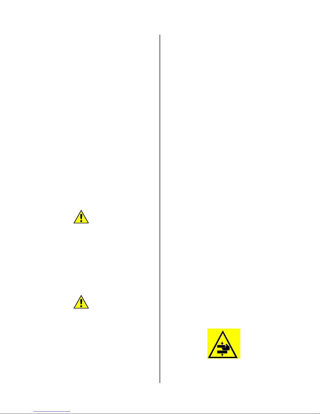
ATTENTION!
Chocking, injuries and
permanent invalidity risks!
Not respecting the following instruction, may
cause damages to people, things and animals.
Installation and maintenance of the here
described machines must be trained by
authorised personnel, which knows the product
and respecting the European Rules in matter of
industrial machines installation.
Reparation made in a not correct way may
seriously compromise the user safety.
Instruction must be read with high attention before
to make the machine work. Instruction must be
available to all the people working with the dryer.
Here described tumble dryers must be used to
professionally drying clothes and linen: any other
use is forbidden, if not before authorized by the
manufacturer.
Before to take out the linen from the dryer, be
sure that the drum is stopped. Never pull your
hands inside the drum, if it is still rotating.
Do not dry in the machine any other different
object; do not dry linen, which entered in contact
with dangerous stuff like explosives, detonating
explosives or inflammables. Linen entered in
contact with this substances, need to be rinsed or
aired before to be dried.
Do not dry linen which has been soaked in
substances dangerous for the operator health, like
poison or cancerogenic stuff.
To avoid risks of fire or explosion, do not
approach to the machine with combustible or
inflammable substances.
The use of this machine is forbidden to people
under 16 years of age.
Children must not play with this equipment.
Packing materials must be kept out of the reach of
children.
Detergents must be kept out of the reach of
children.
Children and pets must be kept away from the
equipment door when it is open.
External supplementary connection to the
machine release the manufacturer from any
responsibility if they are not properly done.
WARNINGS
Working with opened sides is forbidden!
In order to avoid burnings or accident it is
forbidden to remove, even temporarily, the
protection panels and the safety systems!
Page 5
E100301X rev
It is forbi
d
metallic o
b
emergenc
y
described
p
Each time
the safety
d
To know
t
working is
The dryer
s
burns dan
g
Burns ma
y
- The co
n
the dry
e
- The co
n
its ope
n
- The c
o
during
t
- The co
n
On the ma
if one of
t
must repla
S
External
p
during the
Dryer mu
personnel
in the roo
m
READ C
A
OPERAT
I
INFOR
M
Any servi
c
operated
o
to work o
n
5
den to in
jects insi
d
, please
f
rocedures
the dryer
evice corr
e
he machin
compulsor
y
BU
R
, because
er.
be caused
tact with
t
r;
tact with t
h
ing;
ntact with
he mainten
tact with t
h
chines are
hem shoul
d
ce it with a
tuck near
d
anels can
machine w
o
st always
and with at
!
REFULLY
T
NG IN CAS
E
ALL THE
ELECTR
O
e on the
e
nly by qu
a
the mach
i
troduce b
a
e the dru
m
ollow alw
a
is starter,
c
ct working
e and its
s
!
NS DANG
E
of its natu
r
by:
he linen t
a
e door ins
the heat
ance;
e fluxing st
fixed the f
o
be dama
g
new identi
c
ried linen
e
reach hig
h
rking.
be used
least one
o
HE INSTR
U
OF BLAC
K
USER ABO
CUTION
D
lectrical p
lified pers
o
ne, cut off
rs, sticks
. In case
ys the h
e
heck alwa
!
afety devi
RS
e, present
s
ken out fr
o
ide, followi
n
ing batteri
e
am parts.
llowing lab
ed, the u
s
al one.
xit.
temperat
u
by train
e
ther opera
t
CTION FO
R
OUT, AN
D
UT THEM.
ANGER
a
rts must
nnel. Bef
o
the electri
c
or
of
re
ys
ce
a
m
g
es
el,
er
re
ed
or
by
re
al
s
u
P
o
nco
Olaoron
U
a
S
a
vagunThtodr
Wdidi
I
nlig
u
nTh
U
c
a
3
.
T
hreth
W
t
h
-
-
-
-
pply.
wer and c
o
ly by m
ntrary the
w
n the elect
r
bel was stu
unstuck, it
e.
O
P
ser must be
during the
w
ssume a ve
r
udden or
n
oided beca
u
ainst the
d
loading.
e other pe
o
distract th
e
yer.
hile workin
g
stracted b
y
straction.
the room
w
hting must
pleasant fl
a
ese instruc
ser must al
w
refully the r
u
MANUFA
C
e instructi
o
placing, bu
t
e safety an
d
ith referen
c
e manufact
u
The ma
c
and acci
d
The machi
Periodical
missing;
Manual in
s
ntrolled ci
nufacture
r
arranty c
o
ic board, t
h
k. If this la
needs to be
ERATOR
P
CONDI
T
in perfect p
s
orking cycle
tical postur
e
ot controll
e
se of the ri
s
ryer chassi
s
ple in the l
a
operator,
, the oper
a
TV, radi
LI
G
here the
m
be at least
o
shing must
b
ATT
ions do not
ays pay hi
g
les.
TURER LIA
ns written
completing
accident pr
e
e to what i
s
re is not re
s
hine use
d
ent prevent
i
ne was not
c
and/or prog
r
truction wa
s
rcuits can
b
personn
e
ndition ex
p
e here be
l
bel should
b
replaced b
y
SYCHO-P
H
IONS
ycho-physi
c
, the user m
in front of t
h
d moveme
ks of dang
e
, i.e.: duri
n
undry room
who is wo
r
tor do not
o or any
GHTING
achine is i
n
o
f 300-500
l
e avoided.
ENTION!
cover all p
o
h attention
BILITY
in this ma
n
the duties
d
evention la
w
written in
t
ponsible wh
oes not re
s
ion laws in f
o
orrectly ins
t
rammed m
a
not respec
t
21/02/1
4
e modifie
d
l, on th
e
ires.
ow warnin
g
e damage
d
an identica
l
YSICAL
al condition
;
ust always
e machine.
nt must b
e
rous knock
s
g the drye
r
do not hav
e
king on th
e
have to b
e
source o
f
stalled, th
e
ux intensity
;
ssible risks
.
and respec
t
ual are no
t
eriving fro
m
s.
his manual
,
en:
pect safet
y
rce;
alled;
intenance i
s
ed;
Page 6
E100301X rev5 21/02/14
- Defects occurred in the power supply;
- Not authorized modification made on the
machine;
- The machine is used by not authorized
personnel.
4. UNPACKING
The machine must be controlled at the delivery
moment, any external or inside damage dues to
the transport, must be reported immediately to the
forwarder.
ATTENTION!
Moving the machine, remember that the dryer
centre of gravity is located in the last third of the
machine height.
Machine must be completely unpacked next to the
installation place. Straps must be cut and the
covering packing material must be taken off.
Packing materials must be wasted following the
rules in subject of environment protection.
Using a key, take away the nuts on the machine
base which are fixing the dryer to the pallet
(frontal and back).
ATTENTION!
Check the machine net and gross weight on the
technical data sheet sent with the machine: it
must comply with the available lifting means.
ATTENTION!
Pallet cannot be used as normal dryer support!
The machine must always be installed without the
pallet and positioned as described in the relative
paragraph.
ATTENTION!
The machine can be moved only when it is fixed
on its pallet: the machine handling must be done
only by trained and competent personnel.
5. MACHINE IDENTIFICATION
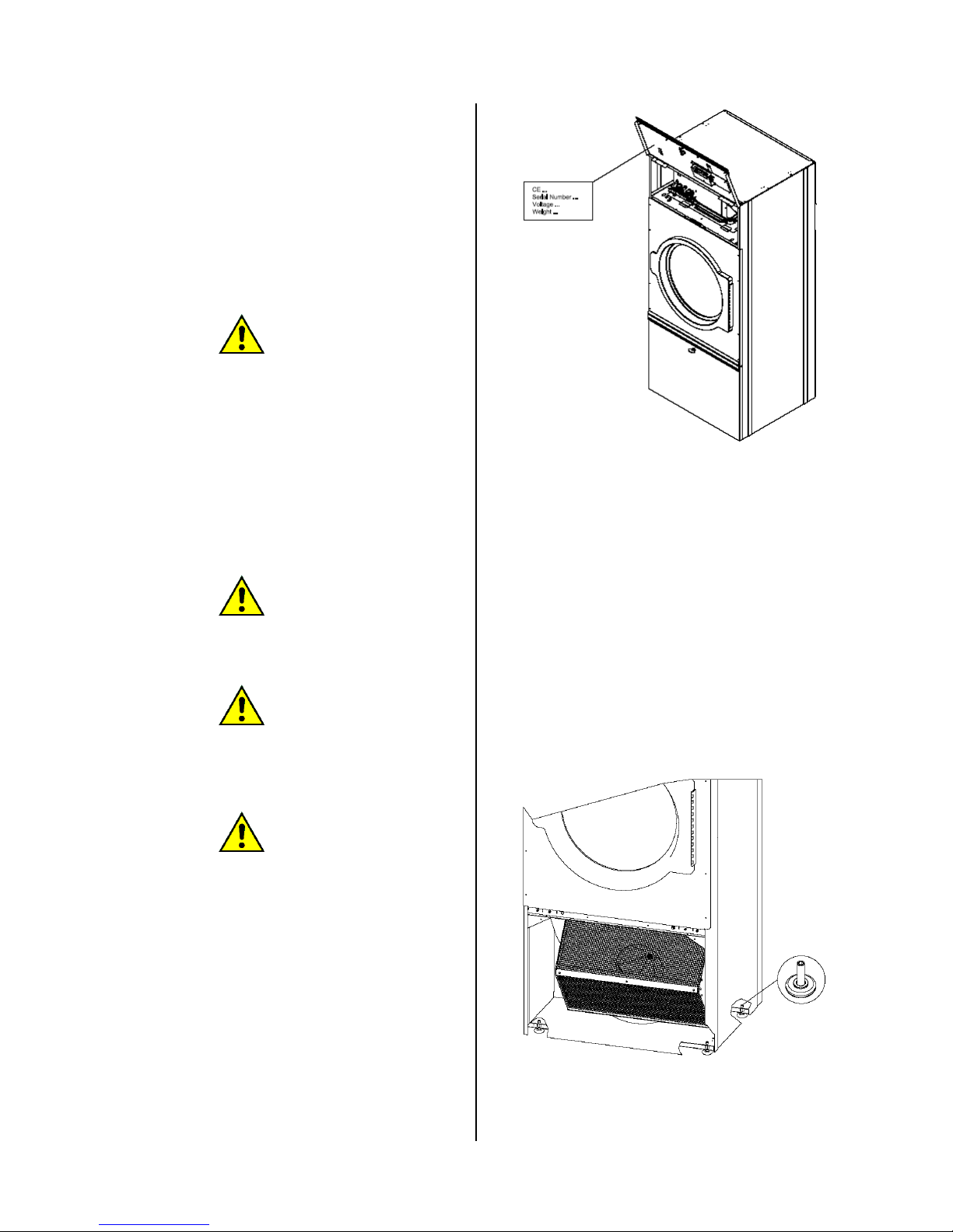
The dryer is identified by the sticker reporting the
machine serial number, model, power and
technical characteristics.
Be sure that the electrical, hydraulic, steam, gas,
compressed air connections are complying with
the sticker data.
Spare parts and / or services require the correct
model identification.
If the serial number sticker is tampered, missing,
removed or damaged in a way that does not allow
a correct machine identification, the dryer
installation and service can be difficult and the
warranty automatically expires.
6. INSTALLATION AND POSITIONING
Installation must be trained by qualified personnel.
Machine must be positioned on a plane surface
horizontally and in a stable way using the
adjustable feet at the dryer base. Feet can be
adjusted from outside, screwing and unscrewing
them until the dryer is correctly positioned.
In models where it is provided, the feet can be
adjusted from inside using a 5mm hexagonal key
after the filter door and the back panel have been
opened
Always check if the floor can bear the machine
weight written in the technical data sheet The
machine load can be considered totally static. To
calculate the dryer static load, the weight of the
Page 7
E100301X rev5 21/02/14
wet linen to be loaded must be added to the dryer
net weight.
Be sure the floor is clean and high temperature
resistant.
For a correct machine use, working and service,
leave at least 500 mm free surface around the
dryer.
The room temperature must be between +5°C
and +40°C.
Protection class is IPX4.
The room where the machine is installed, must
have enough air change. Please note: the
machine takes air from the room where it is
installed and blow off the humid air coming from
the drying cycle to the outside.
The dryer must not be installed behind a door
which can be closed with a key, a sliding door or a
door with hinges mounted on the side opposite to
the tumble dryer.
Do not install or use a machine if it is damaged.
Do not install a machine in a position where the
door cannot be completely open (a suitable kit can
be provide to change the door hinge from left to
right and vice versa.
ATTENTION!
Clean air must be assured to the machine; air
combined with chlorine, fluorine or other
solvent vapours must be avoided.
Do not use or stock near the machine
benzene, petroleum or other inflammable
stuffs. On the contrary fire or explosion may
be caused.
Keep near the machine a foam extinguisher
which is periodically controlled in compliance
with the rules in force.
7. INSTALLATION: GAS HEATED MACHINES
SPECIFICATIONS
Each gas heated machine must be considered,
independently from the capacity, a gas
equipment.
During the installation, the following rules must be
respected:
- territorially building and fire-prevention rules;
- accident prevention rules;
- CENELEC rules (electric system);
- Rules about the combustible gas use
- Rules about gas system supplied by public
net or GPL gas
- Rules coming from the gas company
- Rules coming from the electricity company
- Other possible local rules.
Air inlet and ventilation openings can be closed
only if the opening condition is controlled and only
if the flame of the gas heated equipment is
possible only when air inlet and ventilation are
open.
The room is correctly aired, even when the gas
exhaust is mechanically operated, if the nominal
thermal pollution of this gas equipment do not
cause depression in the room. In this way a
regular gas combustion and the complete exhaust
of the burn gas are guaranteed.
To dimension the air grating, please refer to the
data written on the machine technical sheet and to
the rules in force. In this way a regular gas
combustion and the complete gas exhaust are
guaranteed.
Air inlet dimensions must comply with the
technical sheet requirements and with the subject
rules in force.
In case the dryer supplied with liquid gas is
installed in a basement, forced ventilation system
must be provided.
ATTENTION!
Never installed a gas heated machine in the
same room where machine using solvents are
installed (example: dry cleaning machine) .
This combination could produce dangerous
substances for the operator and it can cause
steel corrosion.
If a gas heated machine and a machine using
solvents are installed in two separate room, be
sure that there is no possibility of air
exchange between the two rooms.
ATTENTION!
In case of machine equipped with a tilting
system, the machine must be fixed to the floor
using some screw anchor.
Machine must be installed perfectly
horizontally on a floor without elastic reaction.
ATTENTION!
In case of titling machines, there are external
parts which moves during the linen loading
and unloading steps.
For machine dimensions and machine needed
space during the movement, please refer to
the technical data sheet.
8. NOISE LEVEL
The air noise produced by the machine is
producing an A continuous and weighted acoustic
pressure lower than 70 dB.
In case that more machine should be mounted in
line, the sums of the acoustic pressure are:
2 machines: air noise < 73dB
Page 8
E100301X rev5 21/02/14
3 machines: air noise < 75dB
4 machines: air noise < 76dB
5 machines: air noise < 77dB
9. ELECTRIC CONNECTION
Electric connection must be carried out by
qualified technicians and must comply with local
and national rules in force. Check if the supply
data corresponds to the data written on the
machine plate.
To connect the machine use a H05 VV – F cable
or superior, it must be correctly dimensioned
following the data label.
Install before the machine a omnipolar
disconnecting device (i.e.: a circuit breaker) which
need to have a contact opening that allows the
complete disconnection in case one of the
conditions of the over tension III category is
verified. This device must comply with the subject
regulation in force.
Check the main switch, it must be in position “0”.
Open the electric supply door. Open the electric
supply door.
Pass the electric supply cable through the cable
holder supplied with the machine. The cable must
be correctly dimensioned (check the following
table).
Electric supply cable connection must be done on a
series of marked terminal.
Following the kind of heating, which is indicated
on the serial number plate, connect the cable to
the terminals, as indicated:
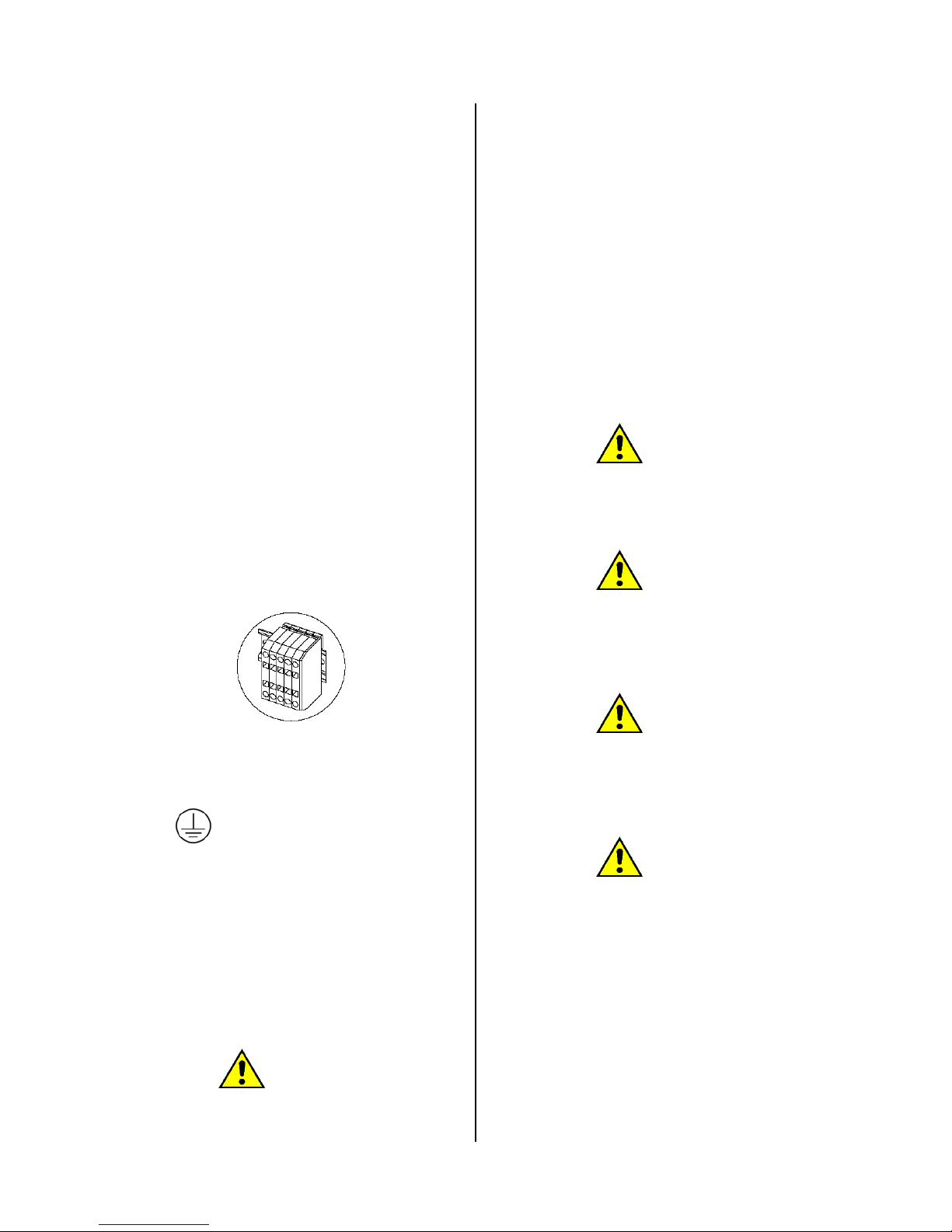
: ground, colour: yellow/green
L1, L2, L3: phase, colour: brown
N: neutral, colour: blue
In case of installation or replacement of the
supplying cable, the ground cable must be at least
5cm longer than the other cables.
The electric diagram is contained in an envelope,
near the electric board.
ATTENTION!
Check the fan rotation direction: it must rotate in
the direction which allows the exhaust air
discharge; it means that the fan motor must
rotated in the direction indicated by the arrow
marked on the motor cover.
Check that the phases are connected in the
correct sequence.
The machine must be connected to an efficient
ground system: the supplier is not responsible in
case this connection is not operated in
compliance with the subject rules in force.
Before to do any maintenance cut the electricity
supply to the machine: for maintenance refer to
the machine electric diagram, which is inside the
machine; anyway, it can be retrieved in any
moment in the manufacturer web site.
The minimum section for the electric cable are
indicated in the attached technical data sheet and
are expressed in mm
2
.
ATTENTION!
The technical data minimum sections can change
according to the connection length. In case the
cable is longer than 5 meters, the cable diameter
must be proportionally increased.
ATTENTION!
The machine connection must always be made
respecting the data written in the serial number
plate (power, supply tension, frequency).
For voltage different from the one provided, ask
for more information to the manufacturer.
ATTENTION!
For machine equipped with drum or fan speed
control, it means for machine equipped with
inverter, a protection by RCD kind B device must
be provided (sensible to the current medium
value).
ATTENTION!
In case the machine is equipped with a supply
cable, and the cable is damaged, it must be
replaced by the manufacturer or by the authorized
technical service;, anyway only qualified
personnel can service the machine, in order to
prevent any risk.
10. GAS CONNECTION
If the machine is gas heated, the necessary
connection with distribution system must be
made: check the machine serial number plate
data, especially supply gas pressure.
Page 9
E100301X rev5 21/02/14
ATTENTION!
The gas maximum pressure admitted is
50mbar. To supply the gas with an higher
pressure, even for short time, may damage the
valve.
The gas distribution system must be realised in
compliance with the rules in force and it must
respect the sections and the pressure suitable for
the installed equipment. .
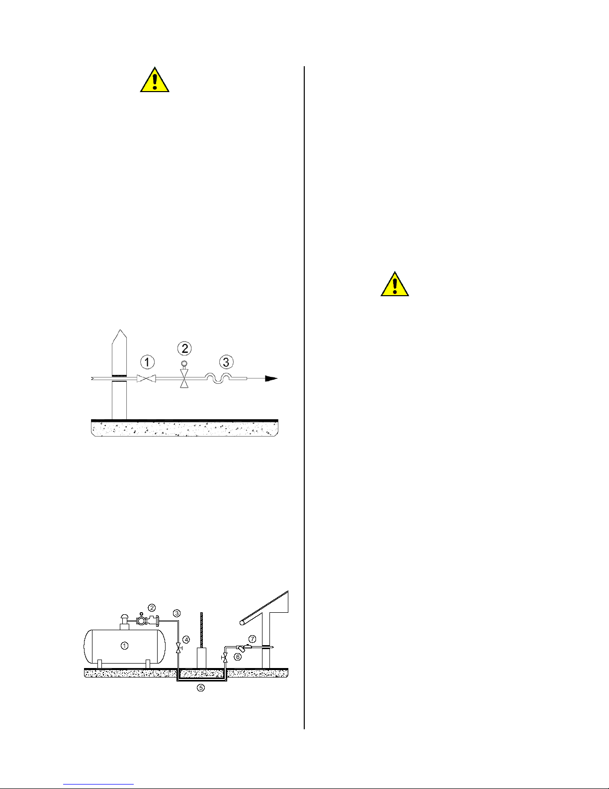
Look to the following picture: before the machine
must be installed a rapid gas interceptor cock (1);
the gas cock must be near the dryer and in an
easy reachable position. The cock must comply
with the rules in force and must be an approved
model.
A low point pressure switch must be provided (2).
The connection to the gas system must be made
using a no-vibration joint (3); if flexible tubes are
used, these must be in stainless steel DIN 3384 or
DIN 3383.
The gas system must be realised in compliance
with the rules in force. The dryer gas connection
has a dimension, which is written in the technical
data sheet; this dimension do no must be
reduced.
The next picture shows how the machine should
be connected in case of gas cylinder with high
pressure: in this case a two steps reduction
system is necessary; it must be realised in
compliance with the rules in force.
A first 1.5mbar governor must be connected after
the high pressure gas cylinder (1), after that a
safety valve with the appropriate dimension must
be installed (2).
The high pressure tube (3) is interrupted by an
interceptor cock (4) and then it follows protected
(5) below the compartments division area border.
Before to enter in the room where the machine is
installed, a second interceptor valve must be
provided and then a filter (6) and a second
governor (7) which brings the pressure to the
correct working value.
11. GAS CONNECTION: TIGHTNESS TEST
All the joints between system and dryer must be
tightness tested .
To make this test, it is suggested to use a leak
finder spray; otherwise the joints can be covered
with a foamy substances, which must not be
corrosive. In both cases, bubbles must not be
created.
ATTENTION!
It is forbidden to use free flame for the
tightness test!
12. GAS CONNECTION: THERMAL POWER
Each dryer tested in the factory is prepared for the
kind of gas which is written in the sticker near the
serial number plate.
If the machine is predisposed for a gas which
does not correspond to the kind available in the
installation place, then it is compulsory to make
the dryer adaptation. In this case, the authorised
after sales centre must be informed.
The dryer working with the expected thermal
power depend on the inlet pressure and the gas
calorific power, but also depend on the nozzle, the
gas pressure arriving to the nozzle and from a
correct supply of primary air.
The pressure of the gas arriving to the machine
must be included in the limits written on the gas
type tables. It the pressure is not included in the
limits written in this manual, the dryer cannot be
started.
If the verified gas pressure is different from the
tables values, please contact the gas company or
the company which realised the gas system.
The GAS Lower Calorific Power, which must be
asked to the gas company, must correspond to
the one indicated in the technical data table.
13. GAS CONNECTION: GAS INLET
PRESSURE CONTROL
The inlet gas pressure must be controlled using a
digital or liquid measure tool. (precision: at list 0.1
mbar).
- Close the interceptor device.
- Open the sealing screw of the gas valve
pressure tube connection indicated with
“Pin”.
- Connect the manometer.
- Open the interceptor device.
Page 10
E100301X rev5 21/02/14
- Start the dryer following the user instruction
- Check the inlet pressure, with the burner
working.
- Switch off the dryer.
- Close the interceptor device.
- Take off the monometer.
- Close the screw of the gas valve pressure
tube and control the tightness.
- Open the interceptor device and control test
the tightness.
The dryer must not working if the gas pressure is out of
the limit shown in the reference table.
14. GAS CONNECTION: FINAL TEST
Once the connection works are taken over, the
equipment and the installation must be controlled.
It is necessary to control:
- that the connection are made respecting the
instructions written in this manual;
- that the safety rules and the laws about this
subject are respected;
- that gas connection are tightness tested.
Switch on the machine following the user manual
instructions controlling the burner lighting on and
the flame aspect.
Do a gas test with the volumetric method. Using
the gas contactor, control how much gas was
used in a fixed time unit: this value must be
compared with the values in the tables.
15. HUMID AIR AND BURN GAS EXAUST
The humid air and burn gas exhaust system must
be realized following the rules in force.
To avoid lack of humid air and noise, the exhaust
joints to the outside must be made tight with high
temperature resistant material (filler, putty,
silicone preparation.
Gas heated tumble dryer are B22 equipment, it
means they are gas equipment which depend on
a aired room without any wind protection device
with blower behind the burning room.
Dryer burned gas must be brought outside
through a chimney.
Burn gas and humid air pipe must be the shortest
possible one and it must be rising to the exhaust
chimney.
In the lowest point a condenser drain must be
provided, this drain derivation must observe the
local rules in subject of water drain connection.
The dryer is equipped with a suction fan which
produces its typical noise while working.
To reduce the noise level, a muffler can be
installed on the drain (it can be found in
specialised shop).
16. STEAM CONNECTION
Only for steam heated tumble dryers, a
connection to the steam system must be provided.
This connection must be performed by qualified
personnel in compliance with the national and
local rules in force.
Steam must satisfy the minimum requirement
which are written in the technical data sheet; all
system parts must be certified.
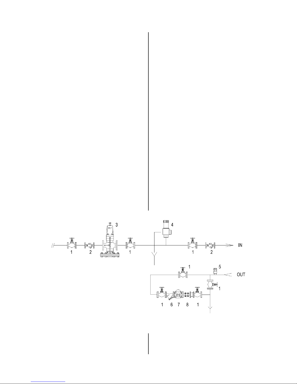
The steam system must be realised following the
below diagram:
System elements are identified as below::
1) On - off valve;
2) Filter;
3) pressure reducing valve (if necessary)
4) Safety valve
IN) Machine steam exchanger inlet
Page 11
E100301X rev5 21/02/14
ATTENTION!
In order to be efficient, the safety valve must
be of a adequate size to provide to the
maximum steam system rate.
5) Vacuum breaker valves
6) Filter
7) Inverted bucket steam trap
8) Flow indicator
OUT) Machine steam heater outlet
ATTENTION!
Drying productivity depend on the steam
heater efficiency.
Dryer can work with the steam pressure range
referred in the technical data sheet, anyway
lower is the pressure, more poor are the
machine performance. In order to avoid too
much longer drying time, the pressure should
be at least 5bar.
17. COMPRESSED AIR CONNECTION
Connection to a compressed air system is
necessary for some dryer models: check the
equipment data sheet.
System must be performed by qualified personnel
in compliance with national and local rules in
force.
Connection between system and dryer must be
tight tested; it is suggested to use a leak finder
spray. In case of air leaks, stop them.
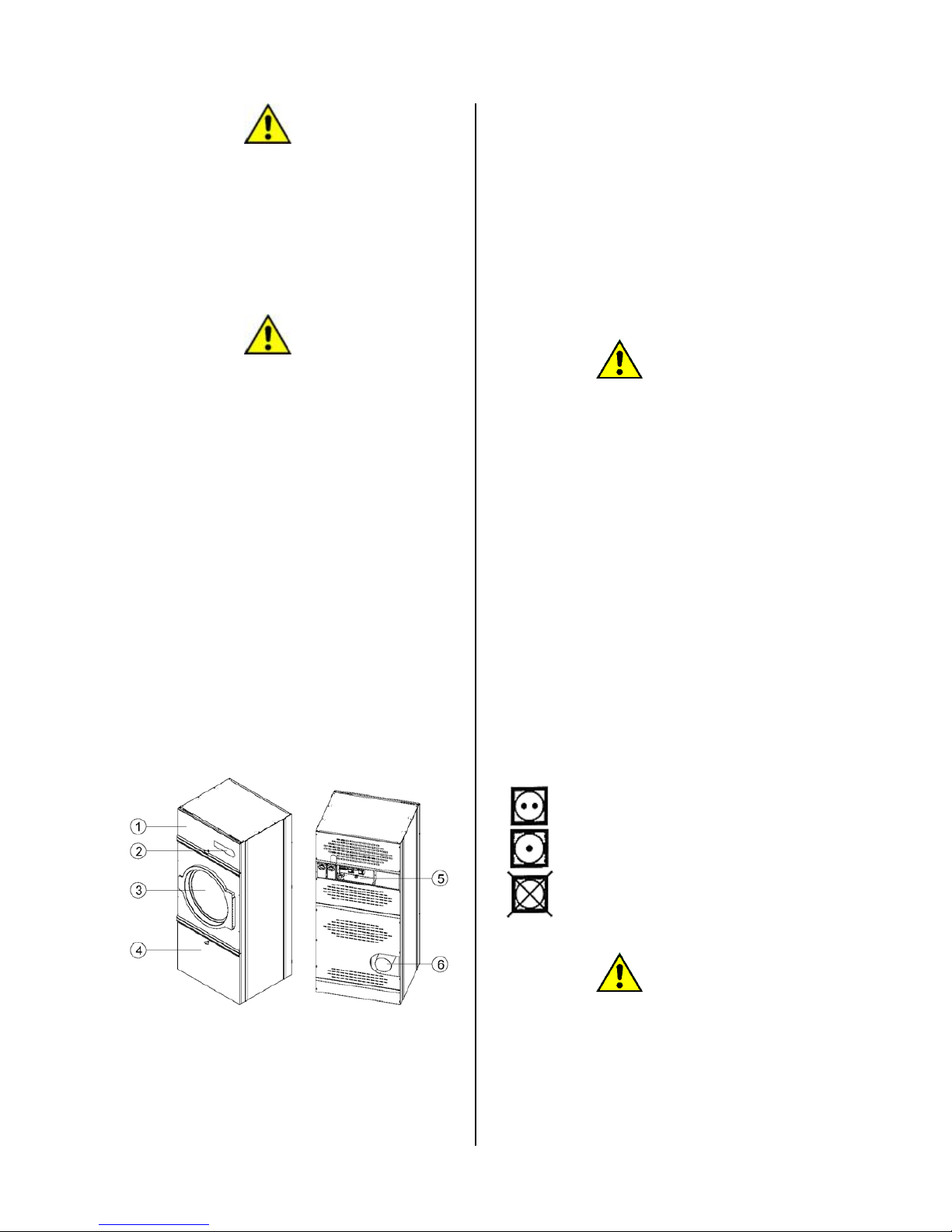
18. MACHINE DESCRIPTION
The dryer is characterized from some elements
which must be known before to use the machine.
The point nr 1 identifies to the heater door. In
case of service, the door can be opened using the
plastic key supplied with the machine, inside the
documents envelope.
Only competent and specialized personnel is
allowed to access to the electric board.
The point nr 2 identifies the control board area,
which can be electronic (microprocessor) or
electro-mechanic (double timer).
The point nr 3 identifies the door of the dryer.
The point nr 4 identifies the filter door. It must be
open each time the filter needs to be cleaned. The
access to the filter must be allowed only to
specialized an competent personnel.
The point nr 5 identifies the electric connection
box and a part of the electric system.
The point nr 6 identifies the humid air exhaust
(always) and the burn gas exhaust (in case of gas
heated machines).
ATTENTION!
Air intakes on the machine back must be
always free. The air passage must not be
limited in any way.
19. PREPARE THE LINEN
Dryer must be loaded on the base of the data
written on the serial number plate: the dryer must
not be loaded with a weight above the nominal
load written on the serial number plate.
Before to decide the most adequate program,
divided the linen into groups, which should be
homogeneous for kind of fabrics or fibres, in order
to reach a uniform drying inside the drum.
Only spin linen must be loaded into the dryer.
Always be sure that batcher or other object are
not among the linen.
Be sure that, during the washing, softener (or
similar products) were used in compliance with
the linen manufacturer instructions.
Before to dry the linen, be sure that the garments
instructions allow the tumbling. The linen must be
wet washed.
Below some international symbol explication:
Normal temperature drying
Low temperature drying
Do not tumble.
ATTENTION!
Do not use the machine if chemical products
were used to wash.
Do not use the machine in case of self-igniting
fabrics.
Linen to be dried must not have been in
contact with dangerous substances such as
Page 12
E100301X rev
explosives
In case
o
acetone,
removers,
remove w
a
with an
e
completel
y
This linen
m
to be dried
Subjects
s
caps, wat
e
one side
o
latex foa
m
rubber par
t
Do not dry
Be sure th
a
used in co
m
Check the
with dama
g
Closes zip
p
ribbons an
Metallic e
l
closures,
protect th
e
shocks, w
itself.
20. START
Switch on
t
the machin
e
In case of
s
valve to l
e
hammering
closed to o
p
In case of
interceptor
v
Be sure th
a
model equi
p
position, th
a
working cy
c
Before to s
always to
paragraph).
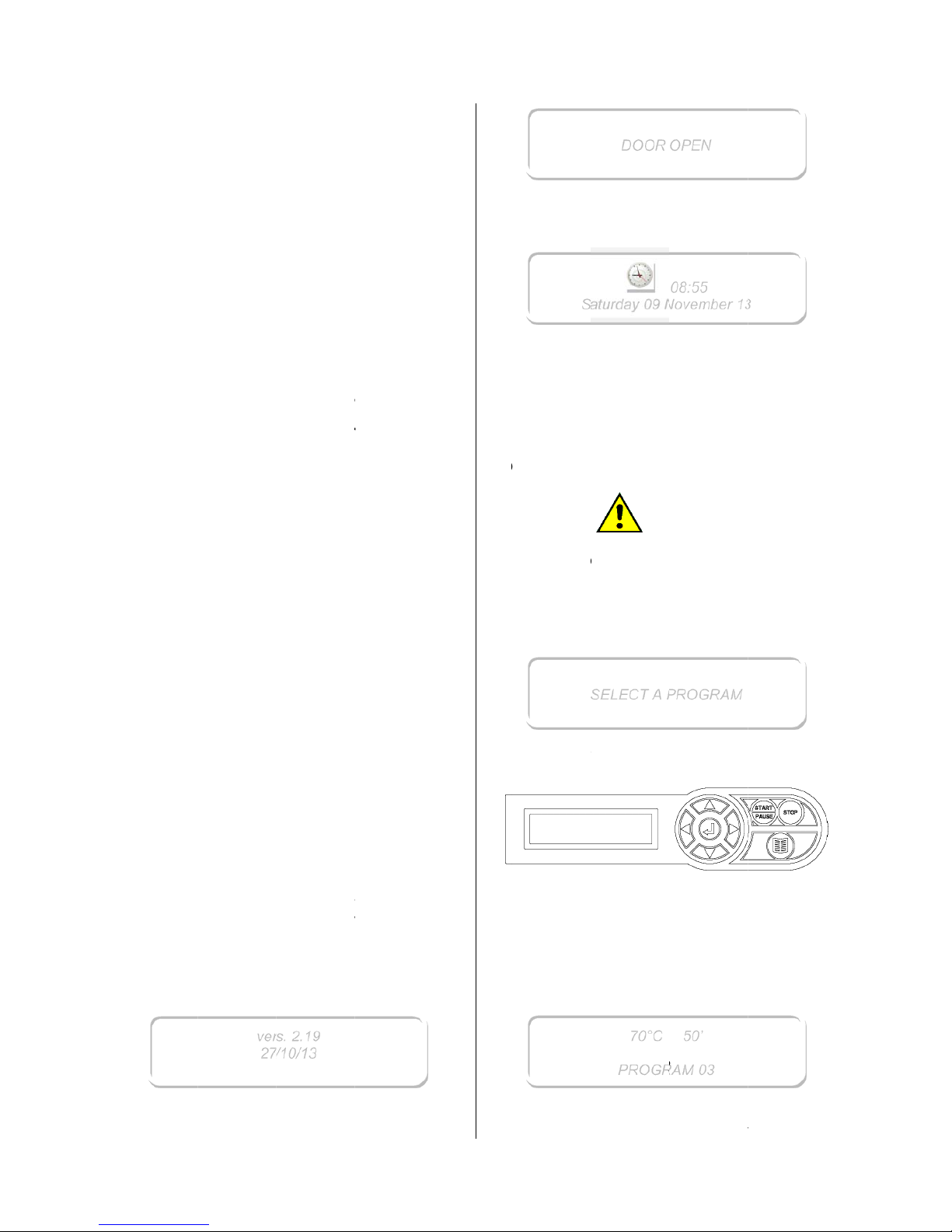
When the
date and v
e
A
fter that t
h
5
, detonatin
g
f linen s
o
alcohol,
p
turpentine,
x, it must
nough q
u
remove th
e
ust be we
.
uch as fo
a
rproof tex
t
f rubber,
g
parts, an
d
s, must no
t
linen whic
h
t softener
pliance w
i
padded ga
r
ed padded
pers; butto
n
d laces. E
m
ements s
u
must be
w
dryer dr
u
hich could
A PROGR
A
he main sw
.
team heate
t the ste
a
, open the
en position
gas heate
d
alve.
t the emer
g
pped with t
h
t it has not
le or during
tart the ma
c
be tested
machine is
rsion are di
s
e display sh
ver
s27/
or flamma
iled with
etrol, Ker
o
wax and
s
be washed
antity of
se substa
n
ll rinsed an
d
m (latex f
o
iles, items
arments o
r
each fab
r
be dried.
was not w
a
and simila
r
th their ins
t
ments: do
garments.
s the dow
n
pties the p
o
ch as bu
c
rapped i
n
m from s
also dam
a
M
itch to supp
d machines
m enter.
T
gate valv
e
in one minu
t
machine
ency stop
is option) i
s
been activ
a
the transpo
r
hine, safet
y
(see the
starter, so
f
played.
ows:
. 2.19
10/13
bles.
cocking
o
sene, st
a
ubstances
in hot wa
t
detergent
ces.
aired bef
o
am), sho
w
with at le
a
pillows w
i
ic containi
n
shed befo
r
products
a
ructions.
not the dr
y
jackets, ti
ckets.
kles, hoo
k
a cloth
ratches a
n
ge the lin
e
ly electricity
open the g
a
o limit wa
t
slowly: fr
o
e time.
open the g
button (on t
in the corr
e
ted during l
a
t.
devices ne
correspondi
tware rele
a
il,
in
to
er
to
re
er
st
th
g
e.
re
er
es
s,
to
d
en
to
te
t
er
m
as
he
ct
st
ed
ng
se
Wdi
T
h
i
nth
T
h
h
oab
s
h
O
C
d
odr
Wsh
T
ous
Wpo
m
T
hbe
hile the d
o
splayed by
t
e dryer i
s
troduce the
at the drum
e machine
mogeneou
s
ove the o
n
eet and in t
h
nce the dry
e
losing the
d
not stay
c
yer front p
a
hen the do
o
ows:
select a p
r
ing the foll
o
- to
s
- to
s
hen a prog
sition in th
e
odified: see
e characte
r
fore to st
a
S
a
S
or is open,
urns with th
e
ready to
wet linen i
n
is completel
y
must be loa
d
linen; load
e indicate
d
e serial nu
m
r is loaded,
c
ATT
oor, be s
u
losed bet
w
nel.
r is compl
e
ogram, scro
l
wing keys:
croll ahead:
croll back:
◄
ram is visu
a
list are dis
p
the relative
p
istic of the
rt the cyc
l
DOOR
O
0
turday09
N
ELECT A
P
70°C
PR
OGRA
the above
date and t
h
be loaded
side the dr
u
y empty.
d with the
m
ing weight
m
in the te
c
ber plate.
close the do
ENTION!
re that pie
c
een the d
o
tely closed
,
ll down the
p
► or ▲
or ▼
lised, its n
a
layed (the
n
paragraph).
program ca
n
e; in effec
t
PEN
08:55
ovember 1
3
ROGRAM
50’
AM 03
21/02/1
4
massage i
s
e time.
. Before t
o
m, be sur
e
ost possibl
e
ust not b
e
hnical dat
a
or.
es of line
n
or and th
e
the displa
y
rograms lis
t
me and it
s
ame can b
e
Example:
be verifie
d
, after fe
w
Page 13
E100301X rev5 21/02/14
seconds the display will show the drying
parameters.
Program parameters visualisation may be
anticipated or deleted using the ENTER ◄┘ Key.
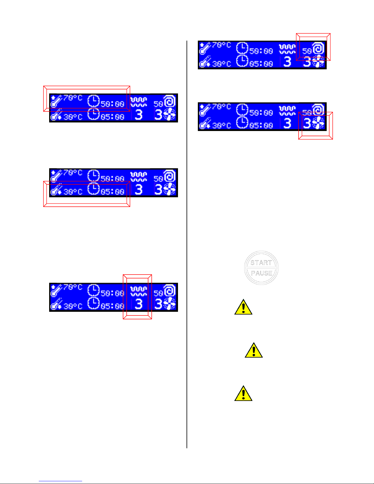
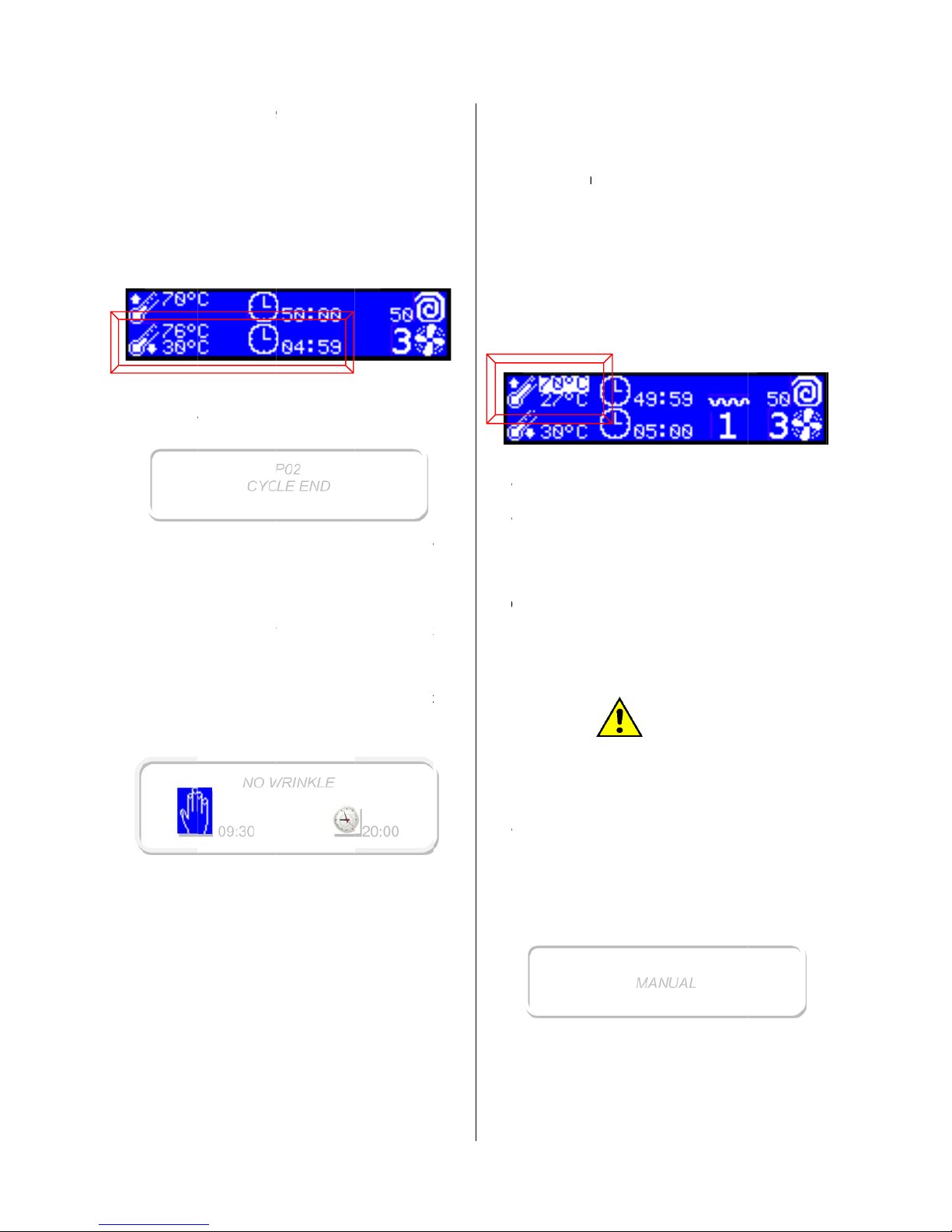
Here below the parameters description:
The parameters shown above on the left are the
drying cycle temperature and length. In our
example the cycle will reach a maximum
temperature of 70°C and will be 50 minutes long.
The ending part of a drying program is a not
heated cycle (called cooling) which is necessary
to assure the integrity of the garments. The box
on the above pictures marks cooling temperature
and the cooling cycle time. The machine will
complete the cycle as soon as one of this two
parameters is reached. In the above example the
cooling cycle will be ended within 5 minutes or the
temperature is lower than 30°C.
In the above picture the drying heating power is
marked (only in case of machine equipped with
the power control option). The dry heating power
are three:
- level 1: minimum power
- level 2: medium power
- level 3: maximum power
the level must be selected according to the kind of
fabric to be dryed. Higher is the selected level,
quicker will be the temperature increasing inside
the drum.
In the above picture the red box marks the drum
rotation speed (only in case of machine equipped
with the DSC option).
In the above picture the red box marks the fan
rotation speed (only in case of machine equipped
with the FSC option). Suction speed levels are
four:
- level 1: very low speed
- level 2: low speed
- level 3: medium speed
- level 4: high speed
The selected level correspond to the air passage
speed inside the drum: higher is the selected
level, quicker is the air passage inside the drum.
When the wished program is displayed, press the
START/PAUSE key to start it.
ATTENTION!
For a correct ironing cycle, the selected program
should assure a 10 – 20 % of linen residual
humidity at the end of the cycle.
ATTENTION!
In case of damages or working anomalies,
shut off the dryer and call the authorized
service centre.
ATTENTION!
At the end of the program the line must never
be left inside the stopped machine: you may
run into a phenomenon of auto combustion!
21. PROGRAM DELAYED START
To select the program follow the instructions given
in the previous paragraph, but instead to press
Page 14
E100301X rev
START/PA
U
The displa
y
The time o
n
the starting
The start
c
hours.
Use the ke
y
time and pr
e
The displa
y
Below the
shows how
missing to t
The count
d
pressing th
e
Once the
c
automatical
If the door
machine s
t
paragraph).
22. PROG
R
While the p
or definitel
y
Pressing t
h
temporary i
n
The displa
y
If the dryer
The pause
5
SE, press
t
shows:
the left is t
h
time is flash
an be del
a
s ▼ and
▲
ss ENTER
shows:
name of t
h
many hour
s
he automati
c
own can
b
key STOP
ountdown i
s
ly started.
is opened
d
ays in pa
u
AM PAUS
E
rogram is r
u
interrupted.
e key STA
R
terrupted.
shows:
door is ope
n
is stopped
STAR
T
14:20
→
PRO
G
04:
P03 P
R
P03
D
he key ME
N
e current o
n
ing.
yed at ma
to fix the
w
◄┘ or STA
R
e program
, minutes a
n
start.
e stopped
or MENU.
ended th
e
uring the c
o
se (see t
h
nning, it ca
n
T/PAUSE
t
, the displa
y
when the
d
ING TIME
14:2
0
RAM 2
14:47
SS STAR
T
OOR OPE
N
U:
e, on the ri
g
ximum for
ished starti
T.
a countdo
w
d seconds
a
at any ti
m
cycle will
unt down, t
e appropri
a
be tempor
a
he program
shows:
oor is clos
ht
24
ng
n
re
e
be
he
te
ry
is
ed
a
gprin
Wplbe
2
3
T
h
m
Athar
D
mau
2
4
T
hhe
E
c
h
D
c
e
D
li
n
t
e
t
w
W
c
h
D
is
r
erig
O
t
h
a
n
ain and the
ogram will
terrupted.
hen the d
o
ease note
very hig
h
. PROGRA
e program
oment, just
p
tumble dr
y
e drying p
e extracte
d
o not leav
e
achine: yo
u
to combu
s
. PROGRA
e drying p
r
ating and e
ch one
aracteristic
uring the he
rtain time a
t
uring the c
o
en for the fi
x
mperature:
t
o paramete
hile the pr
o
eck all the
f
uring the he
always hig
h
al drum te
m
ht (in our e
x
n the right
i
e end of th
e
d 59”).
key START
/
start from
t
ATT
or is open
that the li
n
!
STOP
can be defi
ressing the
ATT
er should
rogram en
d
and hang
o
ATT
the hot li
n
could run
tion.
STEPS
ogram is c
o
d cooling.
of these
value: temp
e
ting step h
e
the fixed te
oling time,
ed time or
u
he step will
f
s is reache
d
gram is ru
ixed param
e
ting step, t
h
lighted (in
o
perature i
s
ample: 27°
C
t is indicate
heating s
t
/PAUSE is
p
t
he point
w
ENTION!
during a d
en temper
a
nitely interr
u
STOP key:
ENTION!
never sto
p
, unless a
l
ut to cool
t
ENTION!
en inside
t
into a phe
n
omposed b
y
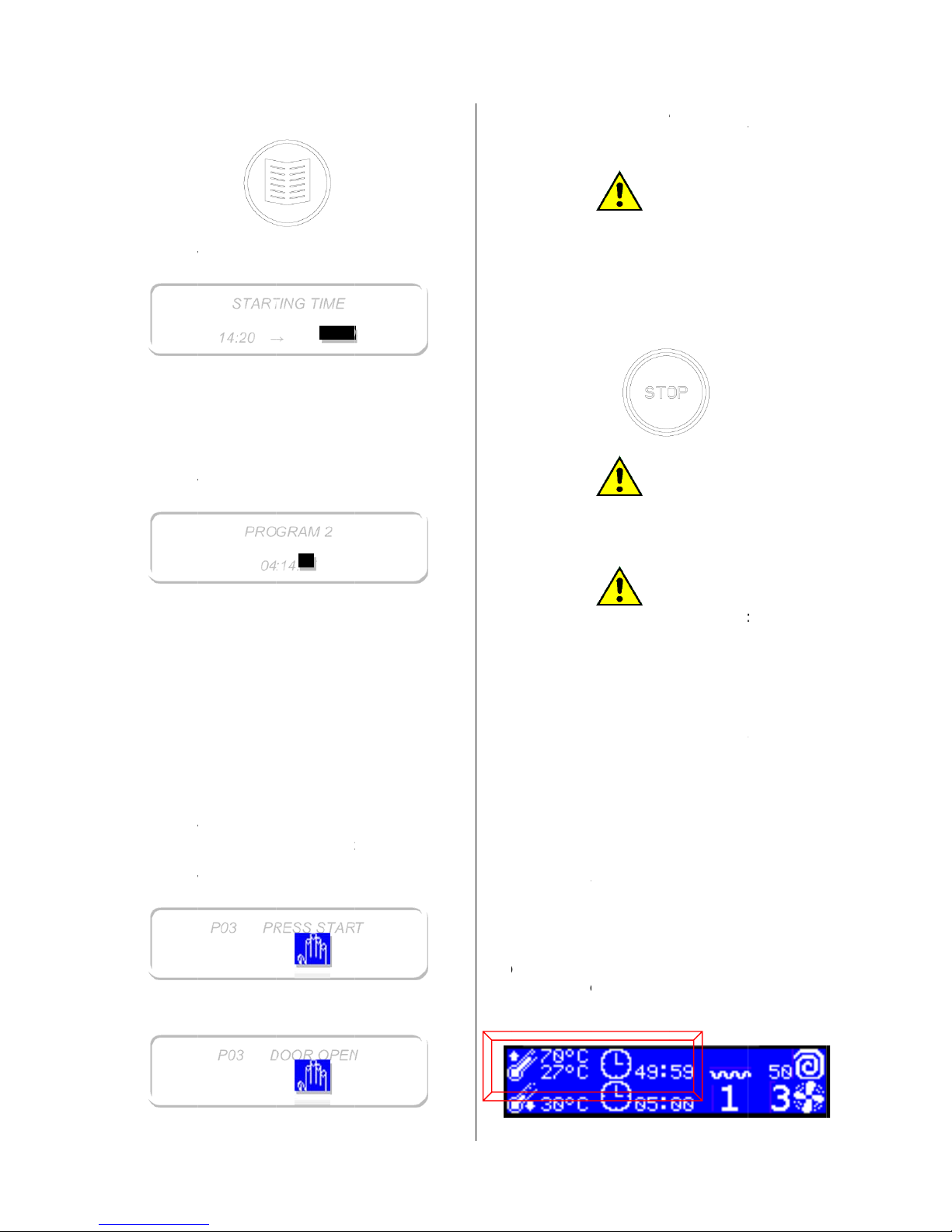
two step
s
rature and
t
machine i
s
mperature.
the machi
n
p to arrived
finished wh
e
.
nning, it is
ters.
e set point
ur exampl
e
flashing b
e
).
d the time
r
ep (in our
e
21/02/1
4
ressed. Th
e
here it wa
s
ryer pause
,
ture coul
d
pted at an
y
ped befor
e
l the item
s
hem down.
he stoppe
d
omenon o
f
two steps
:
has tw
o
ime.
drying for
a
e cools th
e
to the fixe
d
n one of th
e
possible t
o
temperatur
e
: 70°C): th
e
low on th
e
emaining t
o
xample: 49
’
Page 15
E100301X rev
The end p
a
(cooling st
e
damaged.
During the
c
is always d
and the re
a
line (in the
b
On the ri
g
remaining
example: 4’
The cycle e
The displa
y
The name
o
(in the exa
m
stay displa
y
until the do
o
In case the
is not open
,
the relative
again follo
w
No wrinkle
STOP key
o
will stop at
the progra
m
The waiting
displayed o
displayed
o
countdown
NOTE: A
p
the progr
a
programme
NOTE: usi
n
rapid adva
n
directly to t
h
enabled by
25. END O
F
A
t the end
5
rt of the pro
g
p) to be
s
ooling cycl
e
isplayed (in
l drum tem
p
elow exam
p
ht of the
time is
d
and 59”).
nd is signal
e
shows:
f the progr
a
ple: the pr
o
ed until th
e
r is opened
STOP key
if the no w
r
paragraph),
ing the set
v
step can b
e
r opening
t
the progra
m
med length
.
time before
n the left. T
h
n the right,
as soon as
t
revious dry
i
m, if an
d.
g the key
►
ce and sto
p
he cooling
s
IMESA Afte
r
A WORKI
N
of the worki
P
CYC
L
NO
W
09:30
g
ram is a n
o
ure that th
e
the set poi
the below
e
erature flas
h
le: 76°C)
cooling te
m
isplayed (i
d by a 10 s
e
m just end
e
gram nr 2).
STOP key
.
is not press
inkle functio
n
the drum
w
alue.
interrupte
d
he door. An
med time o
the no wrin
k
e no wrinkl
e
this value
he step will
s
ng step ca
n
INITIAL
it is possib
l
the heatin
g
tep. This fu
n
Sales Serv
G DAY
ng day, the
02
E END
RINKLE
t heated cy
c
linen is
n
t temperat
u
xample: 30°
on the abo
perature, t
the bel
o
conds buzz
d is display
The messa
is pressed
d or the d
o
is on (look
ill start to t
u
pressing t
yway this st
r at the end
le step star
t
step lengt
h
w
ill becom
e
tart.
be added
COOLING
e to activat
e
step passi
ction must
ice.
dryer must
20:00
le
ot
re
C)
ve
he
w
.
ed
ge
or
or
to
rn
he
ep
of
is
is
a
to
is
a
ng
be
be
p
udr
C
t
hstTh
2
6TH
Wbe
T
o
k
eTh
T
h
wEwthAmke
O
a
p
a
U
a
n
P
tr
a
2
7
C
wpaTo
►
P
T
h
P
T
h
t at the en
d
um must be
lose all the
e appropri
a
eam and co
m
e dryer do
o
. PARAM
E
E CYCLE
hile the pro
g
modified: t
h
modify a
p
y MENU or
e display s
h
e tempera
t
ith backgro
u
ch time th
a
ay, its value
e key ▲ an
d
ll the displa
ove from o
n
ys ◄ and
►
nce all the
n
while: after
rameters w
ser can ma
k
y time and
i
rogram mo
d
ined perso
n
. MANUAL
ycle can be
hen the lin
e
rameters..
use this c
o
while th
e
ROGRAM”.
e display s
h
ress the key
e display s
h
of the cy
c
emptied an
d
energy sup
te line s
w
pressed ai
r must be le
f
TERS MO
D
ram is run
n
is changes
rogram whil
e
the key EN
T
ows:
ure set poi
n
nd.
t a parame
can be incr
e
▼.
ed param
e
parameter
.
ecessary ch
few second
s
ll come bac
k
e as many
c
n any cycle
ATT
ification mu
nel.
CONFIGU
R
run also in
n was load
e
nfiguration,
display is
ows:
ENTER or
S
ows:
MAN
U
le and swit
c
cleaned.
plies to the
itches: ele
c
r.
ft open.
IFICATIO
N
ing, the par
are not sav
e
e it is runni
n
ER ◄┘.
nt is highli
g
ter is highli
g
ased or de
c
ter can be
to another
anges are
m
the visuali
s
to the usu
a
hanges as
step.
ENTION!
st be oper
a
ATION
a manual c
ed, set the
press once
t
showing
“
TART.
AL
21/02/1
4
hed off: th
e
dryer usin
g
tricity, gas
,
S DURIN
G
meters ca
n
d.
g, press th
e
hted with
a
hted in thi
s
reased wit
h
modified: t
o
one use th
e
ade wait fo
r
ation of th
e
l way.
he wants, a
t
ted only b
y
onfiguration
:
main dryin
g
he key ▲ o
r
SELECT
A
Page 16
E100301X rev
Using the
k
increased
o
Once the
w
or ENTER.
The displa
y
Using the
k
can be inc
r
value.
Once the
w
ENTER an
d
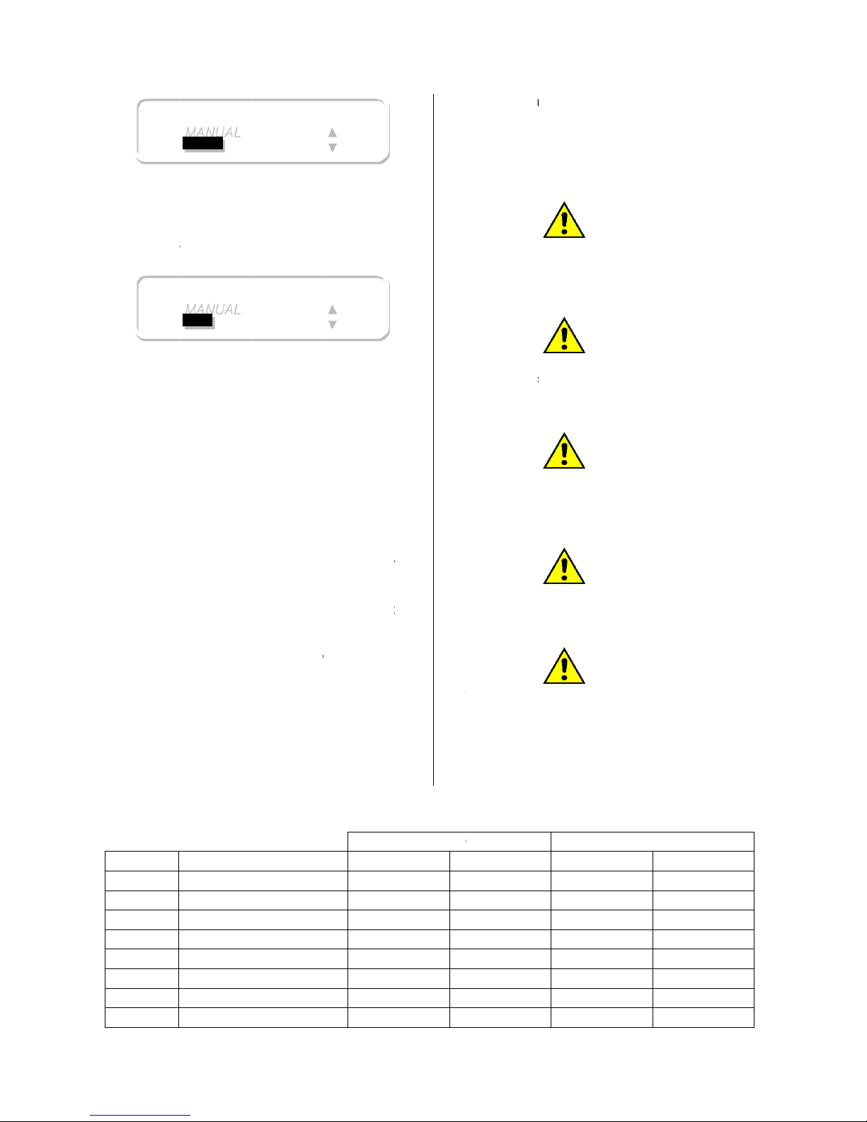
The manua
The set val
u
the next us
e
A
s explain
e
case para
m
drying cycl
e
28. SAVED
The machi
programs. I
each progr
a
Program c
a
relevant pa
r
In case of
option, the
d
- right:
- paus
e
- left:
4
Rotation a
n
the relevan
t
PROG.
01
02
03
04
05
06
07
08
5
eys ▲ and
r decreased
ished time i
s
shows:
eys ▲ and
eased or d
e
ished temp
e
then start
o
l cycle start.
e stay in
m
of a manu
a
d for the p
r
eters can
(see the pr
e
PROGRA
M
ne is deli
v
n the next p
a
m paramet
e
n be freely
agraph.
dryers equi
efault reve
r
40 seconds
: 5 second
s
0 seconds
d pause ti
m
paragraph)
T
RESIDU
A
RESIDU
A
RESIDU
A
RESIDU
A
TTT
T
MANUAL
30 min
MANUAL
40°C
▼, the dryi
n
up to the wi
visualised,
▼, the dryi
n
creased up
rature is vi
s
r directly S
T
emory as d
e
l cycle.
ograms val
u
be chang
e
vious para
g
S
ered with
ge a table i
s
r.
modified as
pped with r
e
sing times a
es can be
.
YPE
L HUMIDIT
Y
L HUMIDIT
Y
L HUMIDIT
Y
L HUMIDIT
Y
IME
IME
IME
IME
g time can
shed value.
press STA
R
g temperat
u
to the wish
ualised, pr
e
ART.
fault value
f
e, also in t
h
d during t
raph).
0 configur
resuming t
explain in t
versing dr
u
re:
modified (s
°
9 8 7 6
549
8
▲
▼
▲
▼
be
T
re
ed
ss
f
or
is
he
ed
he
he
m
ee
I
nopth
T
hte
m
Y
d
e
d
ron Wtoency
S
(
mdr
Av
f
a
m
d
r
DRYIN
G
C
0
0
5
0
0
0
0
0
case of
m
tions, the d
e
e programs:
- he
a
- Dr
u
- Fa
n
e used t
e
mperature
anufacturer
llow stain
s
tergent wa
s
ied to a te
e!
rinkles on
t
o much lo
n
d. If this
e
cle should
b
nsible diffe
ay be cau
s
ying.
oid to dry
brics with s
y
ay cause th
e
um could b
e
Min.
DRY
IRON DRY
DRY
DRY
50
50
40
40
achine e
q
fault para
m
ting power:
m Speed: 4
0
Speed: sp
e
ATT
mperature
indicated
instructions
ATT
on the
not well
r
mperature
h
AT
T
he dried lin
e
ger waiting
vent occur
s
e activated.
ATT
rence in the
ed by sea
m
AT
T
garments
nthetics se
a
plastic me
l
soiled.
°C
40
40
40
40
40
40
40
40
uipped wit
h
eters are th
e
level 3
rpm
ed 2
ENTION!
must com
p
on the
label.
ENTION!
linen mea
n
insed or th
igher than
ENTION!
n can be
c
time after
t
often, th
e
ENTION!
thickness
o
s) may cau
s
ENTION!
with plasti
c
ams. High t
e
lts and cons
COOLIN
G
21/02/1
4
the othe
r
same in al
l
ly with th
e
garment
s
s that th
e
e linen wa
s
the allowe
d
aused by
a
he progra
m
no wrinkl
e
f the fabric
s
e a uneve
n
buttons o
r
mperature
s
equently th
e
Min.
3
3
3
3
3
3
3
3
Page 17
E100301X rev
PROG.
09
10
11
12
13
14
15
16
17
18
19
20
21
22
23
24
25
26
27
28
29
30
HIGH
MEDIUM
LOW
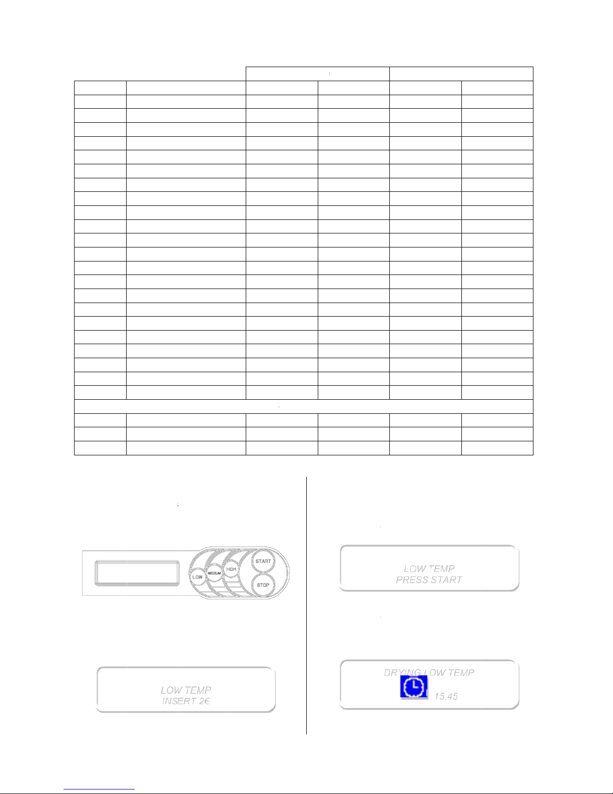
29. COIN
O
In case th
payment s
y
keys, etc.),
user to ch
MEDIUM,
H
If one of t
pressed, th
e
For exampl
the display
It means th
a
5
T
TTTTTTT
TTTTT
TTTTTTTTTTTTT
P DRYER:
e dryer is
stem (centr
a
the keypa
d
oose amon
IGH.
he keys L
O
cost of the
e, when th
e
shows:
t the minim
LO
W
INS
E
YPE
IME
IME
IME
IME
IME
IME
IME
IME
IME
IME
IME
IME
IME
IME
IME
IME
IME
IME
IME
IME
IME
IME
IME
IME
IME
HOW IT W
O
prepared t
o
l cash, coi
n
is modifie
d
g three pr
o
W, MEDIU
M
program is
d
user press
um price for
TEMP
RT 2€
°
765498765498765498765
4Co98
7
RKS
work with
box, prep
a
to allow t
grams: LO
W
or HIGH
isplayed.
the key L
O
a cycle is 2
€
DRYIN
G
C
0
0
0
0
0
0
0
0
0
0
0
0
0
0
0
0
0
0
0
0
0
0
oin Op drye
r
0
0
0
a
id
he
,
is
W
.
A
c
o
a
m
W
W
D
t
htim
Min.
40
40
40
40
30
30
30
30
30
30
20
20
20
20
20
20
15
15
15
15
15
15
s
50
50
50
cording to
ins are ins
e
ount to co
m
hen the pri
c
hen the ST
A
uring the d
r
e chosen
p
e in minut
e
°C
40
40
40
40
40
40
40
40
40
40
40
40
40
40
40
40
40
40
40
40
40
40
40
40
40
the system
rted, the di
s
plete the c
y
e is entirely
RT is pres
s
ying cycle,
rogram an
d
s and seco
n
LOW
T
PRESS
S
DRYING L
O
COOLIN
G
configuratio
play shows
cle purchas
paid, the di
s
ed, the cycl
e
a sliding lin
to the mi
s
ds.
EMP
TART
W TEMP
15:45
21/02/1
4
Min.
3
3
3
3
3
3
3
3
3
3
3
3
3
3
3
3
3
3
3
3
3
3
3
3
3
n, when th
e
the residua
l
e.
play shows:
is started.
riminds t
o
sing dryin
g
Page 18
E100301X rev
During the
changed ju
s
selection
w
any machin
In case the
while the c
y
values ar
e
proportiona
In case th
e
the relevan
t
is displaye
d
name:
Should the
STOP be p
dryer woul
d
The credit
t
this pause.
If the paus
e
automatical
If the door
cycle is def
i
The credit i
s
only to buy
While the
c
program ca
5 minutes
b
shows the
YOU WAN
T
sentence i
s
the corres
p
brought.
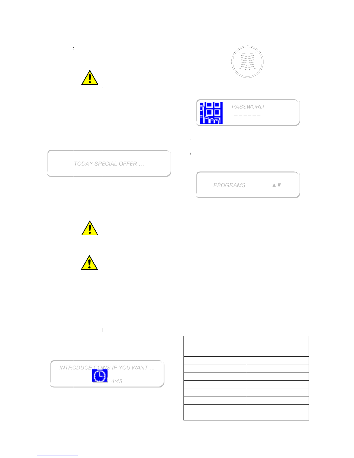
30. HOW T
O
Default par
a
in the user
m
While the
MENU:
INTR
O
5
cycle, the
s
t pressing
ill be auto
m
e stop.
A
selected p
r
cle is runn
different,
lly modify.
field “ADV
E
t
paragraph
)
by turns
w
door be op
e
ressed, whi
be in stand
-
ime count d
A
is longer t
h
ly lost.
A
is opened d
nitely stopp
e
not lost, b
e
drying time
a
ooling tim
e
nnot be cha
n
efore the d
r
message
TO BUY
M
followed
b
onding mi
n
ACCESS
meter valu
e
enu.
machine is
TODAY SP
E
DUCE COI
N
drying pr
o
the new pr
o
atically u
p
TTENTION
!
ogram shou
ing, and th
e
the credit
RT” was c
o
, the advert
ith the sel
e
ned, or the
le the cycle
by.
own contin
u
TTENTION
!
an 5 minut
e
TTENTION!
uring the c
o
d and brou
g
cause the
p
nd not cool
i
is running
ged.
ying cycle e
“INTRODU
C
ORE DRYI
N
y the mini
m
imum time
THE PROG
R
can be m
o
stopped,
p
CIAL OFF
E
S IF YOU
W
gram can
gram key: t
dated with
o
ld be chang
new progr
a
time will
nfigured (s
ising messa
cted progr
a
key PAUSE
is running, t
es also duri
s, the credi
t
oling step, t
ht to the en
d
ayment nee
ng time.
, the select
nd, the displ
E COINS
G TIME”. T
h
um price a
that can
AM AREA
dified enteri
ress the
k
R …
ANT …
be
he
ut
ed
m
be
ee
ge
m
or
he
ng
is
he
.
ds
ed
ay
IF
is
nd
be
ng
ey
T
h
D
S
Tea
Osh
F
r
U
p
r
h
e
m
T
o
If
s
y
m
s
e
P
o
p
v
e
e following
igit the 6
f
ART/PAU
S
ch digit.
nce the s
e
ows:
om this poi
n
sing the k
e
ogramming
- PROG
R
- LANG
U
- DATE/
T
- ENER
G
following
anage thes
e
exit from o
the mach
i
stem, the
a
ade keepin
g
conds from
rogram me
n
eration. T
h
rsion keys
w
Stand
a
configur
a
STA
R
STO
P
LEFT:
RIGHT
DOWN
UP:
▲
ENTER:
MEN
U
P
R
message is
igures cod
e
E key. The
quence is
t it is possi
b
ys ▲ and
areas:
AMS
AGE
IME
Y CONSU
M
paragraphs
areas.
n menu, jus
t
ne is equi
ccess to th
e
pressing t
h
the machin
e
u allows to
e below ta
b
ith the coin
rd
tion
T
◄
►
▼
◄┘
PASS
W
_ _ _
_
OGRAMS
displayed:
pressing
display sho
w
completed,
le to start to
▼ scroll
u
ES
are explai
n
press STO
P
pped with
e program
a
he STOP k
e
switch on (
make all th
le match t
op version
k
Coi
n
config
u
ST
ASTO
not av
a
not av
a
L
O
HI
G
ME
D
not av
a
ORD
_ _
▲
▼
21/02/1
4
6 time th
e
s a star fo
r
the displa
y
program.
p/down th
e
ing how t
o
or MENU.
a paymen
t
rea can b
e
y within 3
0
power on).
necessar
y
e standar
d
eys:
Op
ration
RT
P
ilable
ilable
W
H
IUM
ilable
Page 19

E100301X rev5 21/02/14
31. PROGRAMS
To enter in the program area, please follow the
instruction given in the previous paragraph.
When the display shows “PROGRAMS ▲▼”,
press ENTER ◄┘.
Scroll down the programs with the key ▲ and ▼
until it is displayed the name of the program that
you want to modify.
When the wished program is displayed (in our
example the number 3), press ENTER ◄┘. In this
way it is possible to enter in the program n. 3
parameters modification. The parameters list can
be scrolled up and down using the keys ▲ and ▼.
From this point use the keys as explained below:
- The keys ”▲▼”, to scroll the available
parameters.
- The key “ENTER ◄┘” to enter in a
program and modify it.
- The keys ”▲▼” to modify the value while
it is flashing.
- The key “ENTER ◄┘” to confirm the
displayed value.
- The key “◄ ►” to change the cursor
position to write the PROGRAM NAME.
Here below the program which can be modified
and their possible values.
PROGRAM NAME
Program description displayed during the program
selection and execution. It can be maximum 16
character long.
PROGRAM TYPE
This parameter is used to make the program
works in an automatic way (deciding the residual
humidity at the end of the cycle) or in a traditional
way (deciding the cycle length). The two
parameters are:
- HUMIDITY
- TIME
RESIDUAL HUMIDITY AT THE CICLE END
(only programs “WITH RESIDUAL HUMIDITY”)
Select the value of the residual humidity at the
end of the cycle, once this value is reached the
cycle is ended:
- IRON DRY
- DRY
- EXTRA DRY
WDT T SET
(only programs “WITH RESIDUAL HUMIDITY”)
In this area can be fixed the safety time for the
program stop and the set point temperature for
the automatic cycle.
- DRYING TIME OUT: 1’ ÷ 120’
- TEMPERATURE: 0°C ÷ 90°C
N. STEP
(only programs “TIME”)
A number of heating steps (or cooling steps) can
be set:
- 1 ÷ 10
STEP 1
(only programs “TIME”)
For each step composing the cycle, it is possible
to decide the drying temperature and the step
length:
- TIME: 1’ ÷ 120’
- TEMPERATURE: 0°C ÷ 90°C
STEP 2 … 10
For each step composing the cycle, it is possible
to decide the drying temperature and the step
length:
- TIME: 1’ ÷ 120’
- TEMPERATURE: 0°C ÷ 90°C
COOLING TIME
It corresponds to the length of the cooling cycle at
the end of the drying cycle. This time is
automatically reduced if the set point cooling
temperature is reached before the end of the
cycle:
- 0’ ÷ 30’
COOLING TEMPERATURE SET POINT
It is the cooling temperature which determine the
end of the drying program. If the cooling time
elapse before the temperature is reached, the
program end however.
- 0°C ÷ 90°C
REVERSING DRUM
(with machine with reversing options)
In case the machine is equipped with a reversing
option, this function can be excluded from the
program.
If the parameter “WITHOUT” is selected, the drum
turn always in the same direction (right).
- WITH
- WITHOUT
DRUM RIGHT ROTATION TIME
(machines and programs WITH REVERSING
DRUM)
It is the drum clockwise turning time:
0” ÷ 5’
DRUM STOP TIME
(machines and programs WITH REVERSING
DRUM)
It is the drum rotation pause:
1” ÷ 5’
DRUM LEFT ROTATION TIME
(machines and programs WITH REVERSING
DRUM)
It is the drum counterclockwise turning time:
Page 20
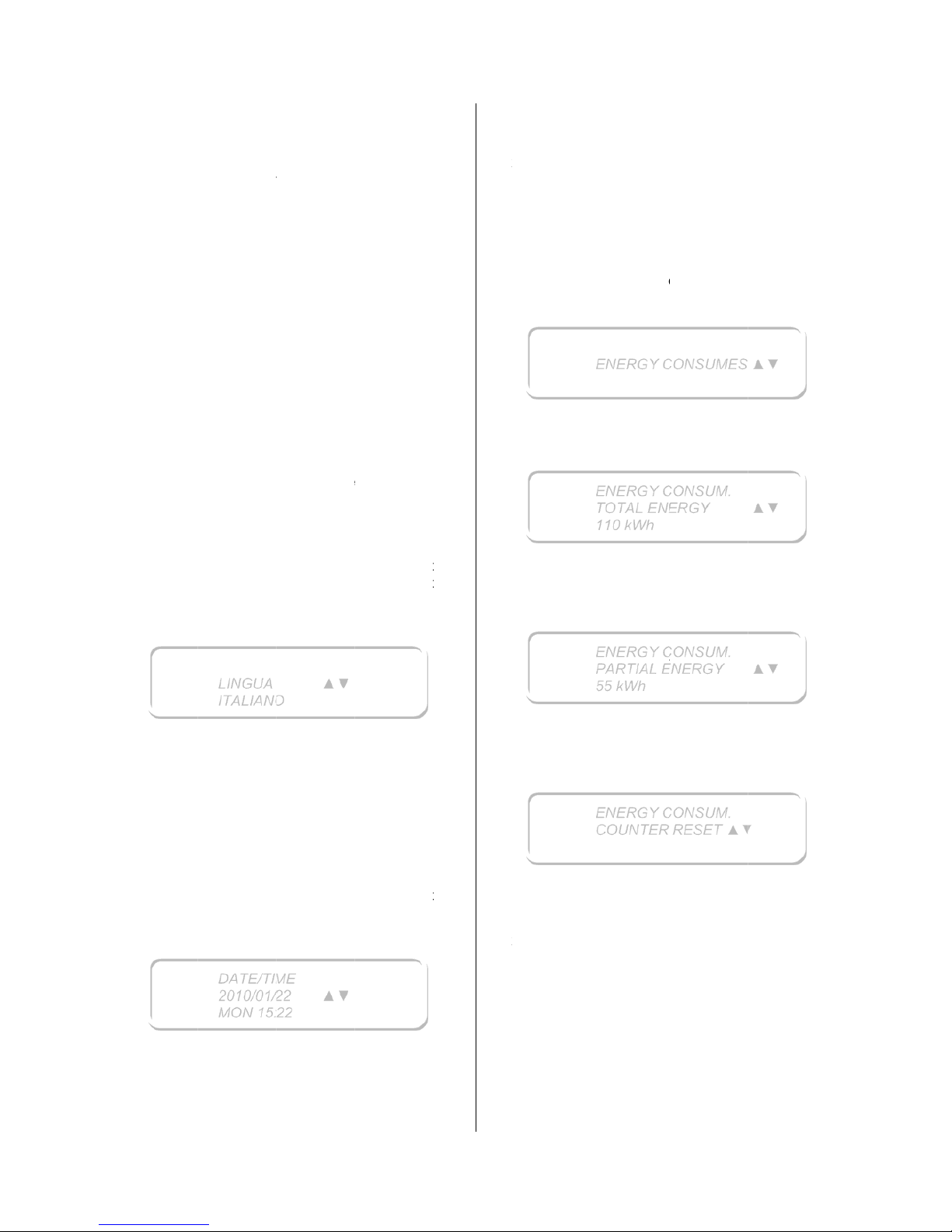
E100301X rev
0” ÷ 5’
(dryers equ
It is the dru
m
20rpm ÷ 80
(dryers equ
It is the hu
m
1 ÷ 4
P
(dryers equ
This param
of the elect
r
MIN 1
MED 2
MAX 3
S
T
(dryer wher
Length of t
h
cycle.
0’ ÷ 30’
32. LANG
U
To enter i
n
language,
pertinent p
a
When the d
Press ENT
E
The langua
flash. Scrol
key ▼ an
d
displayed p
Exit the me
n
33. DATE/
T
To enter in
and the ti
m
pertinent p
a
When the d
Press ENT
E
The year (i
n
Using the
k
the value o
f
Using the
k
5
DRU
M
ipped with
D
speed in
r
rpm
FAN
ipped with F
id air sucti
o
OWER LE
V
ipped with a
eter allow t
o
ic heater:
ARTING C
O
e this functi
o
e initial coo
l
AGE SELE
C
the progr
a
follow the
ragraph.
isplay show
s
R ◄┘.
ge (ITALIA
N
l down/up t
h
▲. Whe
n
ress ENTE
R
u using the
IME MODI
F
the progra
m
e, follow th
e
ragraph.
isplay show
s
R ◄┘.
our examp
l
eys ▼ and
each data.
eys ◄ and
LINGUA
ITALIAN
O
DATE/TI
M
2010/01/
2
MON 15:
2
SPEED
SC option)
ound per mi
n
SPEED
SC option)
n fan speed
EL CONT
R
power level
reduce the
OLING LE
N
n is activat
e
ing cycle b
e
TION
m area a
n
instructions
:
, in our exa
e language
s
the wishe
d
to confirm.
keys STOP
ICATION
area and c
h
instructio
n
:
e 2010) sta
r
▲ it is pos
s
► it is pos
s
▲▼
▲▼
ute:
level
OL
control)
heating po
w
GTH
d)
fore the dryi
d change t
given in t
mple) starts
list using t
language
or MENU.
ange the d
a
s given in t
ts to flash.
ible to mo
d
ible to mo
d
er
ng
he
he
to
he
is
te
he
ify
ify
t
h
W
E
E
x
3
4
T
oin
P
c
o
m
W
P
c
o
T
hus
P
T
h
u
s
P
P
“
N“YEx
M
3
5
T
o
d
ein
W
e value of e
a
hen all da
t
NTER to co
n
it the menu
. ENERGY
enter i
n
structions gi
lease note,
rrect only
achines at t
h
hen the dis
p
ress ENTE
R
nsumption.
e display
s
ed starting
f
ress ▼. The
e display
s
ed starting
f
ress ▼. The
ress ENTE
R
O” is displ
a
ES”. Press
it from pro
ENU.
. NO WRIN
enter in
activate t
h
structions gi
hen the dis
p
ch data.
/time para
m
firm.
using the k
e
CONSUMP
T
the prog
v
en in the p
e
the data
g
if the ins
t
e test mom
e
lay shows:
◄┘ to di
The display
hows how
rom the ins
t
display sho
w
hows how
rom the las
t
display sho
w ◄┘
to res
e
yed: press
ENTER ◄
┘
gram area
u
KLE
the progra
m
e no-wrink
l
v
en in the p
e
lay shows:
ENERGY
C
ENERGY
C
TOTAL EN
E
110 kWh
ENERGY
C
PARTIAL E
N
55 kWh
ENERGY
C
COUNTER
eters are
ys STOP o
r
ION
ram area,
rtinent par
a
iven in th
aller corre
c
ent.
splay the
d
shows:
much ener
g
allation day.
s:
much ener
g
hour count
e
s:
t the count
e
▼ or ▲ to
to reset.
using the k
e
m area to
e function,
rtinent par
a
ONSUMES
ONSUM.
RGY
ONSUM.
NERGY
ONSUM.
RESET ▲
▼
21/02/1
4
fixed, pres
s
MENU.
follow th
e
graph.
is area ar
e
tly set th
e
ryer energ
y
y has bee
n
y has bee
n
r reset.
r. A flashin
g
change it i
n
y STOP o
r
activate o
r
follow th
e
graph.
▲▼
▲▼
▲▼
Page 21
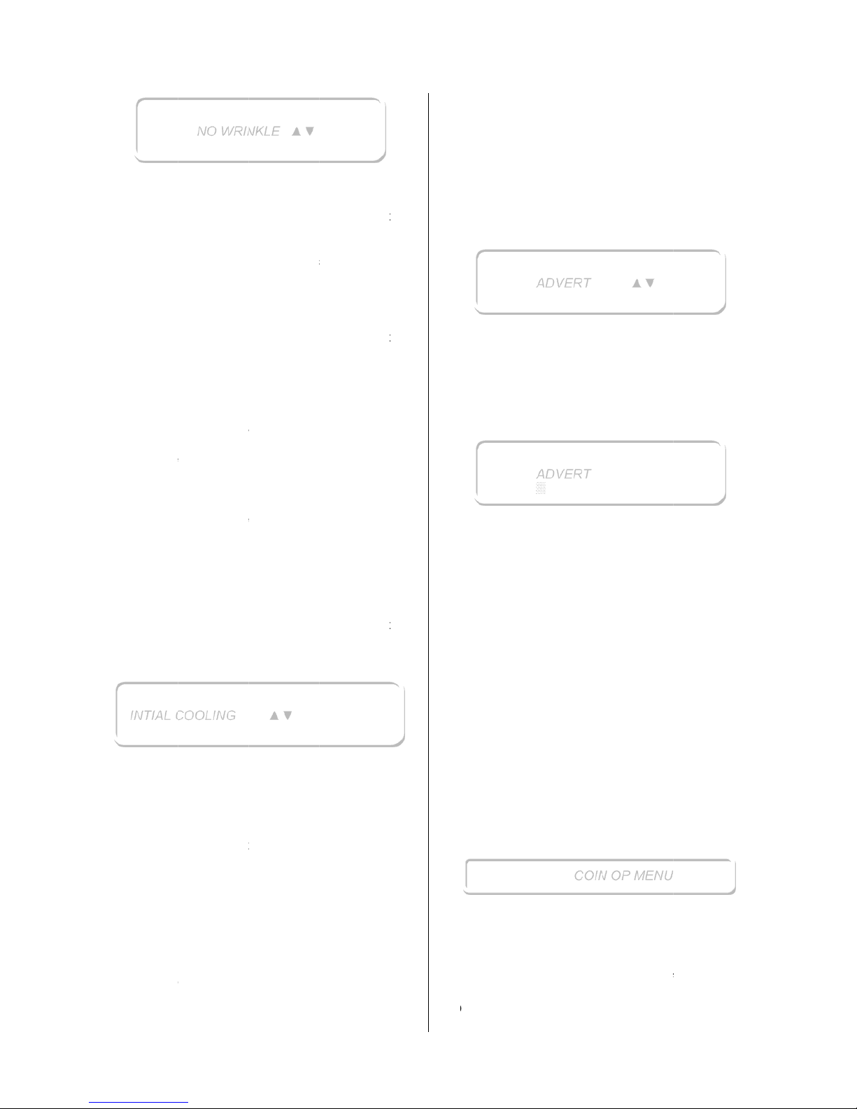
E100301X rev
Press ENT
E
menu.
The param
following:
- NO
W
- END
after
wrin
k
seco
n
- FOR
W
seco
n
cycle
- PAU
S
expr
e
the n
- BAC
K
Valu
e
- MAX
befo
r
36. INITIA
L
To enter i
deactivate
instructions
When the d
Press ENT
E
and ▼ or
▲
Press ENT
E
If it is sele
c
can be se
t
cycle, whic
h
before the
n
37. PAYM
E
If the ma
c
system, th
e
are not ava
i
These par
a
menu or i
n
additional p
- TOT
A
starti
n
INTIAL
C
5
R ◄┘ to
e
eters which
RINKLE: p
o
o YES:
n
after th
e
not o
p
param
e
o NO: no
-
after th
e
door is
n
CYCLE PA
the end of
le cycle s
ds.
ARD: it i
s
ds. Value
v
.
E: how lon
ssed in se
c
o wrinkle cy
c
: it is the l
e
valid only f
o
TIME C
Y
e the dryer
d
COOLING
n the pro
g
the initi
a
given in the
isplay show
s
R ◄┘ to g
o
to select Y
E
R ◄┘ to c
o
ted YES, t
h
in each p
start toge
t
ormal heati
n
NT SYSTE
M
hine is e
q
re are som
e
ilable in the
s
meters are
t
to the CO
arameters
w
L CREDIT:
ng from the
i
NO WRI
N
OOLING
nter in the
can be m
o
ssible valu
e
o-wrinkle
c
cooling en
d
en and r
e
ters fixed b
e
wrinkle cyc
l
cooling e
n
ot open.
USE: it is t
h
the cooling
tart; it is
the right r
o
alid only for
g the drum
onds. Valu
e
le.
ft rotation ti
m
r the no wr
i
CLE: no
w
efinitely sto
p
ram area
t
l cooling,
pertinent p
a
:
into the p
a
S or NO.
nfirm the s
e
en an initi
a
rogram: it i
s
her with th
e
g cycle.
uipped wit
special p
a
tandard ve
r
he ones int
o
IN BOX m
e
hich can be
total amou
n
nstallation d
KLE ▲▼
▲▼
NO WRINK
L
dified are t
are:
ycle will st
a
, if the doo
r
specting t
low.
e will not st
a
d, even if t
e waiting ti
m
before the
expressed
tation time
the no wrin
k
stopped. Ti
m
valid only
f
e in secon
d
nkle cycle.
rinkle len
g
s.
o activate
follow t
ragraph.
rameter me
lected optio
n
l cooling ti
m
a beginni
program st
a
h a paym
e
rameter whi
sion.
the ADVE
R
nu, plus t
w
only read:
t of the cre
d
ate.
E
he
art
is
he
art
he
e
no
in
in
le
e
f
or
s.
ht
or
he
nu
.
e
ng
art
nt
ch
T
o
it,
3
8
T
h
C
T
oin
W
P
t
e
is
T
hpo
If
t
hdrToth
T
h
3
9
T
h
C
T
oin
W
P
U
s
cWMthOM
- DAILY
the da
y
. ADVERT
e “ADVER
T
oin – Op Dr
y
enter i
n
structions gi
hen the dis
p
ress the ke
y
xt, which w
i
working.
e display s
ssible to w
r
the line wi
ere will be
yer is runni
n
compile t
h
e here belo
w
- STAR
T
cursor
m
- STAR
T
figure
a
- STAR
T
selecte
d
- HIGH,
value f
o
e available
. COIN BO
X
e “COIN B
O
oin Op drye
r
enter i
n
structions gi
hen the dis
p
ress MEDIU
sing the L
O
roll the me
n
hen the wi
s
EDIUM to
c
e LOW and
nce the wis
EDIUM to
c
CREDIT: t
o
(starting fro
” menu is
a
ers.
the prog
v
en in the p
e
lay shows:
MEDIUM t
o
ll run on th
e
ows a curs
ite:
h the curs
o
no messag
g.
e message
,
explain lo
g
pressed for
oves throu
g
pressed f
o
t the left of t
h
pressed fo
letter.
LOW to m
o
r the select
e
characters
a
MENU
X MENU’” i
s.
the prog
v
en in the p
e
lay shows:
to set the
W and HIG
H
u paramete
r
hed param
e
onfirm and,
HIGH keys
t
ed value i
s
onfirm. He
r
ADVERT
ADVERT
▒
COI
N
tal amount
m 00:00).
vailable on
l
ram area,
rtinent par
a
display th
e
display w
h
or to indicat
r is compl
e
es appeari
n
, use the k
e
ic:
less then 1
g
h the text.
r 2 secon
d
he selected
r 5 second
s
ve among
t
d figure.
re 29.
s present o
n
ram area,
rtinent par
a
coin box.
H keys, it i
s
.
eter is disp
l
while it is
f
o modify its
displayed,
e below th
e
▲▼
OP MENU
21/02/1
4
of credit o
f
y in case o
f
follow th
e
graph.
advertisin
g
ile the drye
r
e where it i
s
tely empty
,
g while th
e
ys followin
g
second: th
e
s: add on
e
position.
: erase th
e
he possibl
e
ly in case o
f
follow th
e
graph.
possible t
o
ayed, pres
s
lashing, us
e
value.
press agai
n
paramete
r
Page 22
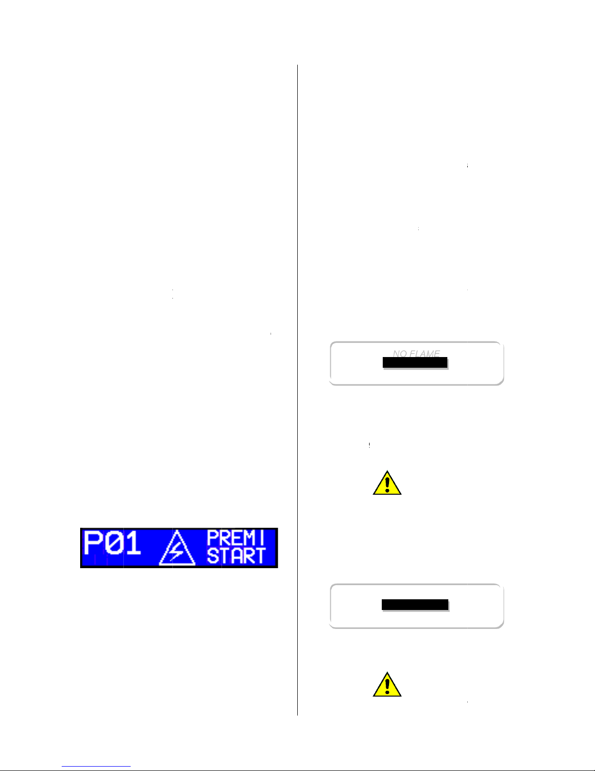
E100301X rev
list of this
m
- COI
N
displ
a
- TOK
E
in c
u
elect
r
TOK
E
- TOK
E
in c
u
elect
r
TOK
E
- DEC
I
whe
n
-
AUTO
To exit the
program le
v
40. EMER
G
In case a q
u
emergency
When the
e
drum stops
When the
emergency
written on i
t
41. BLAC
K
In case of
b
in the drum
In this cas
e
leave it ope
When the
e
will show:
The interru
p
number 1,
possible to
Load the
m
cycle will b
interrupted.
42. WHAT
SMELL
In case the
of gas:
- sto
p
- op
e
5
enu:
: it identifie
s
yed.
N 1: it ide
n
rrency) of
e
onic board i
N 1).
N 2: it ide
n
rrency) of
e
onic board i
N 2).
MALS: nu
m
the price is
o XX: no
o XX,X:
o
o XX,XX:
MATIC ST
A
o If “YES
been
autom
a
o If “NO
”
comple
t
STAR
T
menu or t
o
el, just pres
s
ENCY STO
ick machin
e
stop button
mergency
s
and the dry
e
emergenc
y
stop button
.
OUT
lack out, on
e
and they co
, open the
d
ned.
lectricity wi
ted progra
m
in our exa
m
start it again
achine aga
i
e started fr
o
MUST BE
D
room where
immediate
l
n immedi
a
the curre
n
tifies the va
l
ach impuls
e
nput (termin
tifies the va
l
ach impuls
e
nput (termin
ber of de
displayed:
decimal
ne decimal
two decima
RT:
”: when the
completed,
tically start.
: when th
e
t
ed, the cy
c
is pressed.
go back t
o
STOP one
P BUTTON
stop is ne
e
(if present).
top button i
r is turned
o
ends, s
e
, turning it i
or more cl
o
uld risk to c
a
oor, unload
ll be restor
e
number is
ple), pres
s
.
n and clos
e
m the poin
t
ONE IN C
the dryer is
y the progr
a
tely all t
h
cy that will
ue (express
given to t
al identified
ue (express
given to t
al identified
cimals sho
w
s
payement h
the cy
c
payment
le start onl
y
the previ
o
or more tim
e
ded, press t
s
pressed, t
ff.
t again t
the directi
thes may s
t
tch fire.
the dryer a
d, the displ
displayed (t
ing Start it
the door: t
where it
w
A
SE OF G
A
installed s
m
m;
e door a
be
ed
he
by
ed
he
by
n
as
le
is
if
us
e.
he
he
he
on
ay
nd
ay
he
is
he
as
S
ell
nd
C
4
3
T
hco
h
i
H
d
i
I
n
d
ice
E
a
cIn
o
f
d
iInco
Wtofoke
C
s
h
I
n
r
e
I
nhi
d
i
I
nte
I
n
wind
o
- close
gate
v
- do n
o
matc
h
- do no
all the instal
l
. DISPLAY
E
e micropro
c
rrect dryer
ghlight of a
s
ere below
splayed ala
r
case one
splayed, pl
e
ntre to solv
e
ch one
o
oustically s
i
case of a d
warning: in
rectly to the
case of a
g
uld be displ
hen this al
a
work, but t
h
r a reset. T
y ENTER
◄
ontrol if the
g
own often,
a
case of c
o
placed by: “
case the t
e
gher than
splay is flas
h
case th
e
mperature i
s
this case t
h
ws;
immediatel
y
alve before
t light on
es or lighte
r
t
smoke;
er to check
t
D WARNI
N
essor repo
r
working a
n
tatus.
a complet
e
ms.
of the follo
ase contac
t
the possibl
f the foll
o
gnalled by
a
al timer dr
y
case the
m
authorized
s
NO F
L
as heated d
ayed:
rm is displa
y
e heating s
y
start agai
n
.
as tap is o
p
sk for a ch
e
AT
T
in op dryer,
NO FLAME
OVERH
E
mperature
i
t
he set poi
ing:
heating
not going
b
AT
T
e suction c
o
NO FL
A
PRESS
E
OVERH
E
the valve
the machin
e
the room
;
he gas leak
G
ts both in c
a
d in case
list of t
h
wing alarm
s
t an author
e problem.
wing alar
m
buzzer.
er, there is
n
achine sho
u
ervice cent
r
AME
ryer, the foll
yed, the dry
stem is sto
p
the heatin
en. In case
ck to the se
ENTION!
the above
PRESS ST
A
ATING
inside the d
nt tempera
t
is stoppe
d
elow the sa
f
ENTION!
ontinues to
w
AME
NTER
ATING
21/02/1
4
ore the ga
s
;
illumination
,
.
se of a no
-
of a simpl
e
e possibl
e
should b
e
ized servic
e
s is als
o
o possibilit
y
ld stop, as
k
e.
owing alar
m
er continue
s
ped waitin
g
g, press th
e
the alarm i
s
rvice centre.
message i
s
RT”
rum is 30°
C
ure, at th
e
until th
e
ety value.
ork to coo
l
Page 23
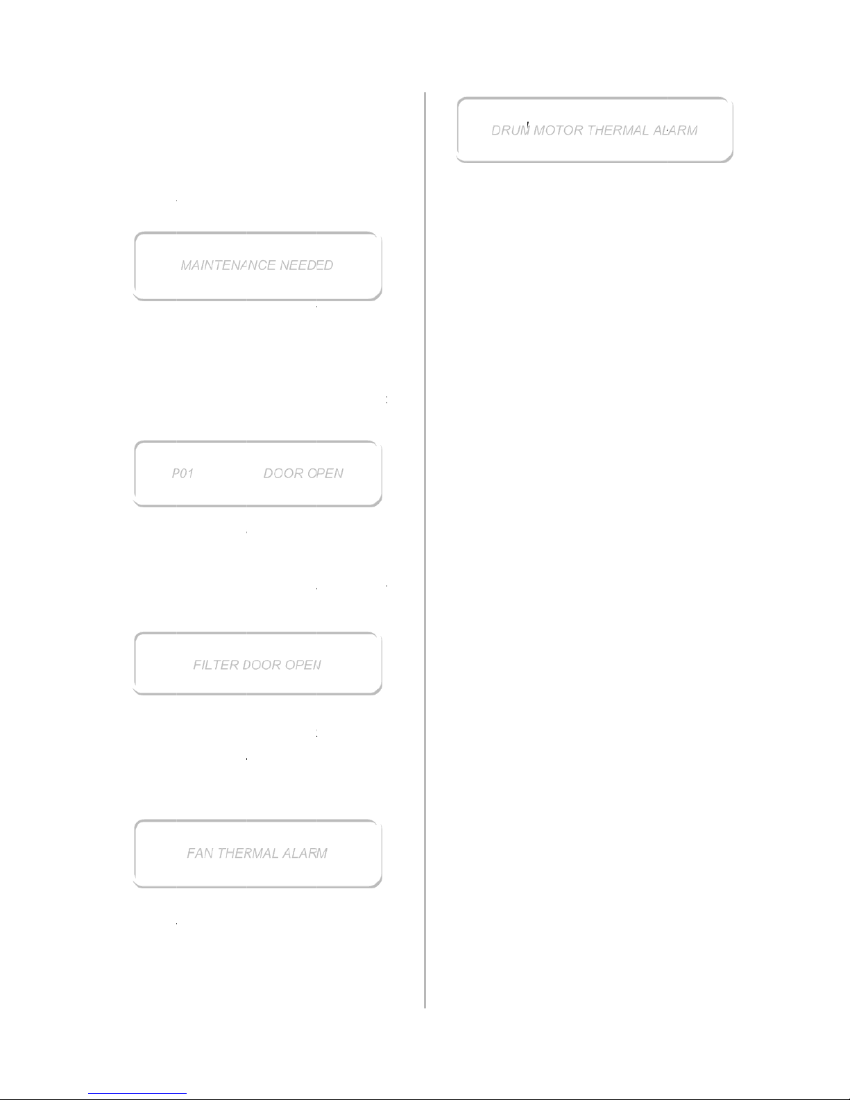
E100301X rev
the linen.
In case thi
s
a check to
a
In case th
e
higher than
shows the
f
Pressing o
n
any other s
i
authorised
maintenan
c
If the door
machine st
o
The machi
n
again the c
y
If the filter
display sho
w
The machi
n
start again
t
If the fan
m
display sho
w
Turn off t
h
service cen
t
If the drum
the display
P
5
alarm is re
n authorize
d
MAINTEN
A
temperatur
the set poi
n
ollowing fla
s
e key, the
m
gnal. Anyw
a
service
c
e.
DOO
is opened d
ps. The dis
p
e is in pau
s
cle pressin
g
FILTER
D
door is o
p
s:
e is in pau
s
he cycle pr
e
FAN
T
otor overhe
a
s:
e dryer an
tre intervent
i
DRUM MO
T
motor over
h
shows:
MAINTENA
01
FILTER
D
FAN THE
R
peating ver
y
service ce
n
NCE NEED
E
e inside the
t temperat
u
hing alarm:
achine star
t
y it is nece
s
entre for
R OPEN
uring the dr
y
lay shows:
e: close the
START.
OOR OPE
N
en, the dr
y
e: close the
ssing STA
R
HERMAL
ts, the dry
e
d ask for
t
on.
OR THER
M
eats, the d
r
NCE NEED
E
DOOR O
P
OOR OPE
N
MAL ALAR
M
often, ask
f
tre.
D
drum is 30
re, the displ
again with
o
sary to call t
the ordin
a
ing cycle, t
door and st
a
er stops. T
filter door a
T.
r stop and t
he authoris
AL
yer stops a
D
EN
f
or
°C
ay
ut
he
ry
he
art
he
nd
he
ed
nd
T
use
rn off the
rvice centr
e
DRU
M
dryer and
interventio
n
MOTOR T
H
ask for th
e
.
ERMAL AL
A
21/02/1
4
authorise
d
RM
Page 24
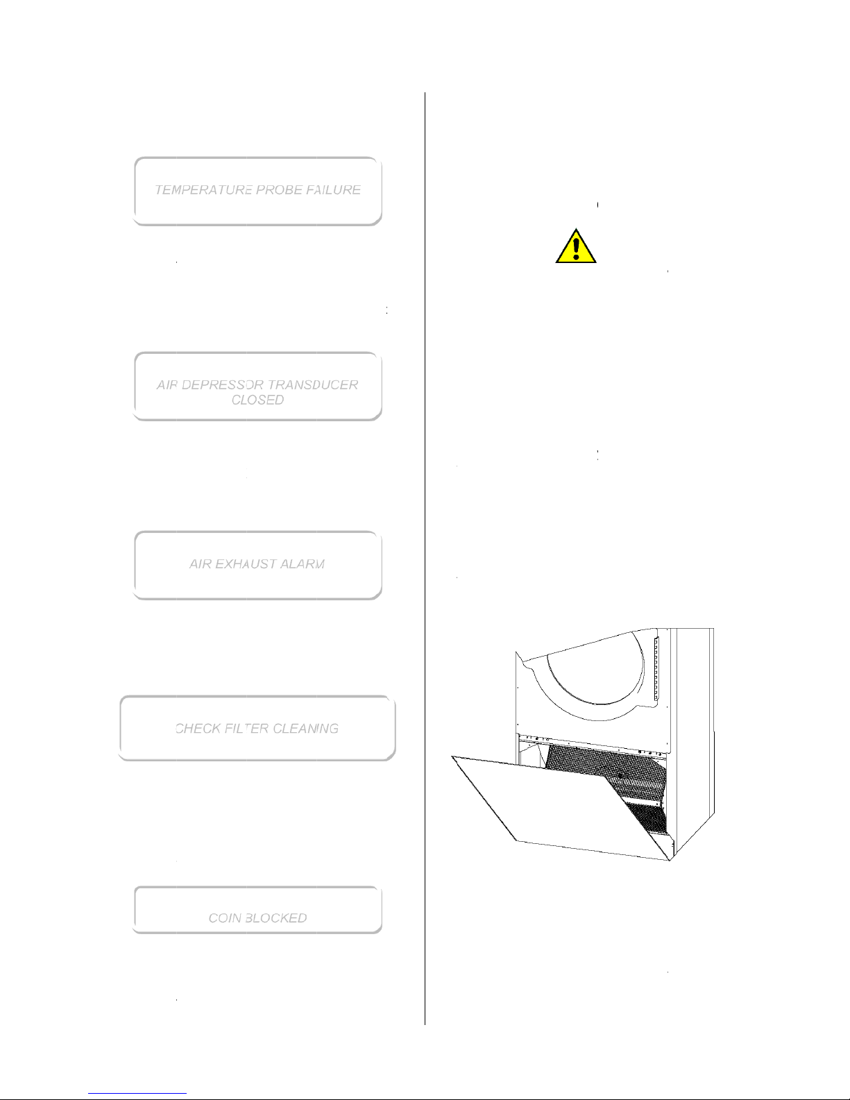
E100301X rev
TE
M
If the temp
e
shows:
Turn off t
h
service cen
t
AIR DE
P
If the air d
display sho
w
Ask for the
If there is
a
the display
Ask for the
F
If the filter i
s
Turn off th
clean the fil
t
If the mac
h
box, the dis
It means t
h
box for mor
Check the
service cen
t
TE
M
AIR
C
5
PERATUR
E
rature pro
b
e dryer an
tre intervent
i
RESSOR T
R
epressor tr
a
s:
authorised
s
AIR E
X
problem
w
shows:
authorised
s
ILTER CL
E
dirty, the d
i
e machine,
t
er.
COIN
B
ine is confi
g
play shows:
at the coin
e than 5 se
c
credit an
d
tre intervent
i
PERATUR
E
DEPRESS
O
CL
O
AIR EXH
A
HECK FIL
T
COIN
B
PROBE F
A
e is damag
e
d ask for
t
on.
ANSDUC
E
nsducer is
ervice centr
e
X
HAUST
ith the hum
ervice centr
e
ANING CH
E
splay show
s
open the
f
LOCKED
ured to w
o
is blocked i
onds.
ask for t
on.
PROBE F
A
R TRANS
D
SED
UST ALAR
M
ER CLEAN
I
LOCKED
ILURE
d, the displ
he authoris
R CLOSED
damaged, t
interventio
n
id air exhau
interventio
n
CK
:
ilter door a
rk with a c
o
nside the c
o
he authoris
ILURE
UCER
NG
ay
ed
he
n.
st,
n.
nd
in
in
ed
T
h
a
I
nco
If
a
l
4
4
E
i
npe
A
b
e
m
D
I
nnemAvinexFobesp
E
A
Atfro
T
o
d
rth
I
n
b
eFopaIn
fil
is alarm a
p
cycle is run
this cas
e
mpleted, e
v
the coin b
o
arm would
b
. DRYER
M
There i
s
d
a
ch ordina
r
tervention
rsonnel.
ll the dryer
fore any
achine.
o not use w
a
the follo
w
cessary
aintenance
a
oid the fluf
f
not neces
s
haust).
r the daily
used. Do
onge, solv
e
CH CYCL
E
the end o
f
m the fluff.
clean th
e
awer (for s
o
e filter room
case of mo
removed.
r model wi
t
ying attenti
o
both cases
ter using t
h
pears also
i
ning, i.e. w
h
the prog
r
en if the ala
r
x should s
u
e automatic
a
AINTENAN
C
a risk of i
n
maging th
e
y and ext
r
must be
supply con
n
maintenanc
e
ter or stem
t
ing paragr
a
ordinary
nd how the
y
backlog ar
o
ary in cas
e
cleaning, a
ot use abr
a
nts or metal
l
each dryi
n
filter, ope
n
me model
s
.
el with filte
r
h filter dra
w
n to not da
m
, the fluff m
u
e hands,
d
f the coin b
en extra ti
m
am is goi
rm stays dis
p
uddenly ma
lly reset.
CE
ATTENTIO
N
juring you
r
equipmen
t
aordinary
m
operated
b
ection mu
s
e intervent
i
to clean the
phs are e
x
and
e
y need to b
e
und the dr
y
of dryer
w
wet and so
f
sive produ
c
lic objects.
g cycle, cl
e
the door
), in order
t
door, the fi
er, empty t
age the ne
t
st be remo
v
do not us
e
21/02/1
4
locked whil
e
e is bought
.
g on an
d
layed.
ke free, th
e
!
self or
.
aintenanc
e
y qualifie
d
t be cut of
f
on on th
e
parts.
plained th
e
xtraordinar
y
scheduled.
er (this not
e
ith externa
l
t cloth mus
t
ts, abrasiv
e
an the filte
r
or pull th
e
o access t
o
lter must no
t
he filter ba
g
.
ed from th
e
sharpene
d
Page 25
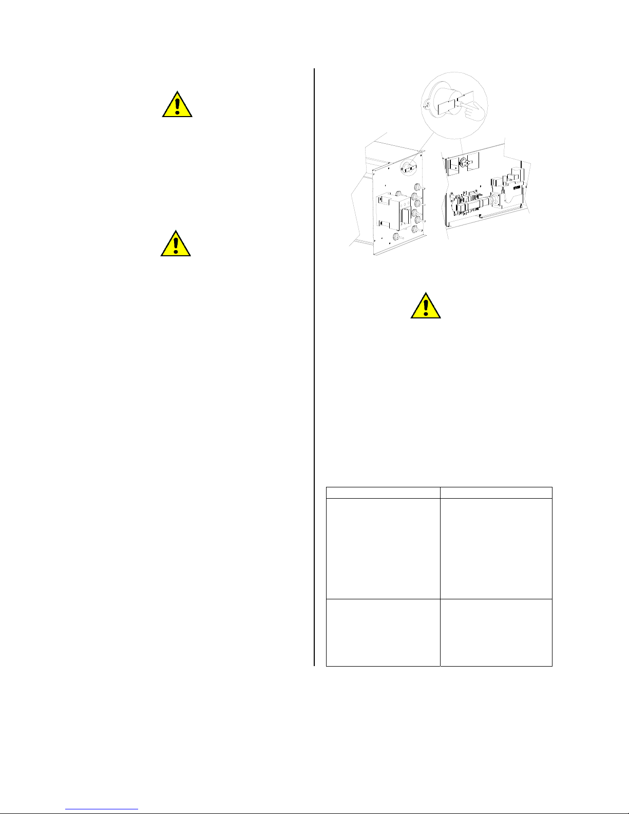
E100301X rev5 21/02/14
object
ATTENTION!
Never use the dryer without the fluff filter. If the
filter is damaged, replace it immediately.
EACH WEEK
Check the drum cleaning condition: there must no
be deposit on the drum. Be sure that there are not
stains due to melted nylon seams, button and
other.
ATTENTION!
To clean the drum, do not use a high pressure or
a water continuously cleaner.
The drum must be cleaned with a dried and soft
cloth.
EACH THREE MONTHS
Check the fan and the suction cleanness. Check
the drum and the ventilator motor cooling fans
cleanness.
EACH YEAR
An authorized service centre must be contacted
to:
- clean the burner or the heating element from
fluff and other
- clean the dryer inside
- control the pneumatic tightness
- control the gas tightness
WHEN NECESSARY
In case the temperature inside the burner reaches
too much higher values, a safety thermostatic
paste stops the heating system: the drum
continues to rotate, but the heating system stay
deactivated.
The thermostatic paste need to be manually
rearmed, in this case it is necessary to turn off the
dryer, cut all the energy supply, open the above
frontal door and press the brown coloured push
button near the thermostatic paste.
If the problem should repeat, switch off the dryer
and call the authorised service centre.
ATTENTION!
In case of tilting dryers, before to start any
maintenance service, control that the air
system is completely discharged and no
pneumatic movement can be activated, even
when if there is no electricity supply.
In case of maintenance with mechanism,
which are not in the rest position, be sure to
mechanically and safely block the pneumatic
mechanism.
45. DRYING PROBLEMS
In case of not satisfying drying results, please
check the following table to find a solution to the
most usual problems.
PROBLEM SOLUTION
The linen presents
yellow stains.
Check if the linen is
correctly rinsed and all
the soap is washed
away.
The PH value must be
included between 5
and 6.
The linen is yellowed.
Check that the drying
temperature is
complying with the data
on the label.
Page 26
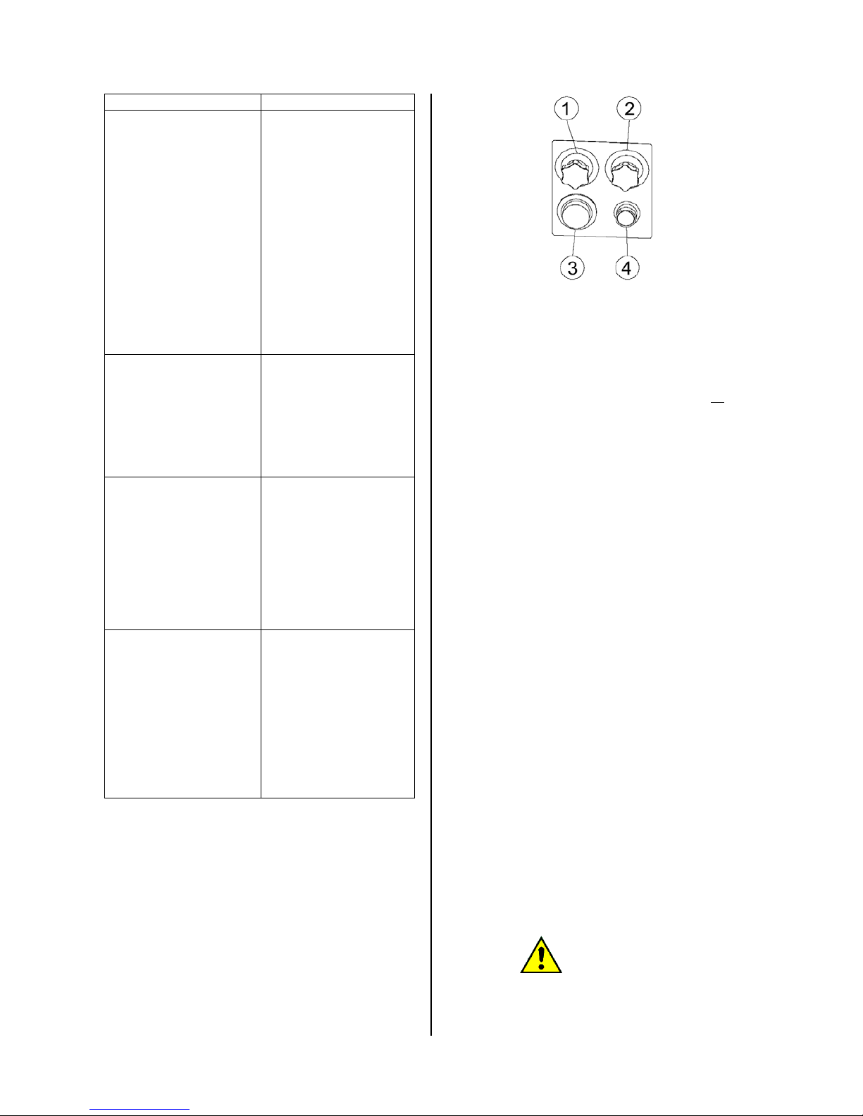
E100301X rev5 21/02/14
PROBLEM SOLUTION
At the end of the cycle
linen is still wet.
Check the selected
temperature, it could be
too much low.
Check the air suction
system, it could be
blocked and its
efficiency limited.
Check the exhaust
system: it could be to
much strong avoiding
the air to pass through
the linen.
At the end of the cycle
linen is hardened
Check the cycle
temperature, especially
in case of linen fabrics.
If temperature is too
much high, the fabrics
is going to harden.
At the end of the cycle
linen is felted
Check clothes label
and their conformity
with the dryer use,
especially in case of
wool or mixed wool
fabrics. In this case
avoid a complete
drying.
The drum is scratched.
Some clothes are
damaged, torn
Metallic objects like
buckle, hooks,
fastenings must be
covered with a cloth
before to dry, so the
drum is protected by
scratches or collisions,
which could also
damage the linen.
46. DUAL TIMER DRYER: USE
Until now it was treated only the case of a
microprocessor controlled dryer.
It is also available a simplified dryer model, which
is controlled by electromechanical commands.
For this dryer the control is the following:
Marks 1 and 2 indicate the heating and the
cooling timers.
Marks nr 3 indicates the thermostat and the
marks nr 4 the START button.
In this picture is not preset the RESET button,
which equips only gas heated dryers.
Load the machine and close the door; all the
instructions given in the previous paragraphs must
be respected.
Fix the heating and cooling times using the two
timers; fix the drying temperature using the
thermostat.
Press the START button.
The START button lights on and the cycle starts
and runs until its end.
In case the drum door or the filter door are
opened, the cycle stops: to start it again press
START.
If the START button does not light on, and the
cycle does not start, when the button is pressed
ask for the intervention of an authorised service
centre.
Only in case of gas heated dryers: if the burner
does not start, the red RESET button lights on to
signal the flame control block.
In this case the machine continues to work, but
the heating is deactivated. To unlock the flame
control, press the RESET button until it lights off.
In case the RESET button light on often, ask for a
dryer check to an authorized service centre.
47. TILTING DRYER: USE
In case the dryer is equipped with a tilting system,
to the previous paragraphs indication, the
following remarks need to be added to control the
right and left drum rotation.
In this case the controls can be given using a
remote keyboard.
ATTENTION!
When the machine is in the tilting step, or the
pneumatic door is opening, the user must not
stay close to the machine and control the
dryer using the remote keyboard.
Page 27
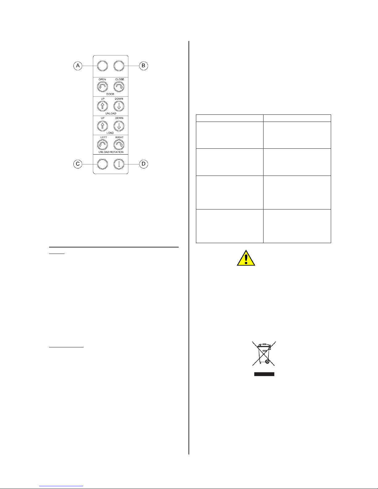
E100301X rev5 21/02/14
Before to start the tilting, always wait for the end
of the running cycle.
To activated or deactivate the keyboard use the
key – switch (D).
When the keyboard is on, the microprocessor is
off.
If the keyboard is on, the green light is also on (A).
LOADING (for machine equipped with two way
tilting)
Switch on the keyboard using the key. To open
the door press at the same time the activation key
(below at left) and the “DOOR OPEN” key.
When the door opening is complete, make the
dryer bend to the back pressing at the same time
the activation key (C) and the “LOAD UP” key.
When the loading is completed, bring the dryer in
the original position pressing at the same time the
activation key (C) and the “LOAD DOWN” key.
Close the door pressing at the same time the
activation key (C) and the “CLOSE DOOR” key.
Switch off the keyboard using the key (D).
UNLOADING
Switch on the keyboard using the key (D).
To open the door press at the same time the
activation key (C) and the “DOOR OPEN” key.
When the door opening is complete, make the
dryer bend forward pressing at the same time the
activation key (C) and the “UNLOAD DOWN” key.
When the machine is in the unloading position,
the linen exit can be helped by the slow alternate
rotation of the drum (right and left); to make the
drum rotate, press at the same time the activation
key (C) and the “UNLOAD ROTATION” key
(RIGHT and/or LEFT).
When the unloading operation is ended, bring the
dryer to the orginal position pressing at the same
time the activation key (below – left) and the
“UNLOAD UP” key.
Close the door pressing at the same time the
activation key (C) and the “CLOSE DOOR” key.
Switch off the keyboard using the key (D).
48. SAFETY DEVICE CONTROL
After the machine is turned on, before to start the
drying cycle, it is necessary to control the safety
device correct working.
The user should always stick to the following
procedure:
ACTION SEQUENCE REACTION
Start a drying cycle and
open the door…
… the dryer should
stop and stay in pause.
Start a drying cycle and
open the filter door…
… the dryer should
stop and stay in pause.
Press (if present) the
emergency stop button
…
… the drum should
stops and the dryer
should turn off.
As soon as the dryer is
electrically supplied …
… the machine must
be in stand-by waiting
for a command (drum
stopped, fan and
heating deactivated)
ATTENTION!
Safety device must always be tested when the
machine is switch on and before to start the
working shift.
49. SCRAPPING
When the machine life cycle arrives to the end,
please proceed with the machine scrapping
following the country rules, keeping separate the
metallic, the plastic, the glass, the
electric/electronic parts.
The above symbol on the appliance or on the
package means that at the end of its life cycle this
product must be collected separately from other
waste material.
For this appliance waste separation, follow the
rules in force in the Country where the machine is
installed.
A correct waste separation avoid dangerous
impact on the environment and make easier the
material recycling.
Unlawful disposal may caused application of
Page 28

E100301X rev5 21/02/14
administrative sanction, following the rules in force
in the country where the dryer is installed.
ATTENTION!
In case the machine should not be more used
before the dryer disposal, make the door lock
out of service, to avoid that somebody close
himself inside risking his life.
Electric supply cable must be disconnected
and disposed.
50. WARRANTY CONDITION
For the warranty condition, check the
manufacturer price list.
ATTENTION!
To benefit of the manufacturer warranty condition,
the manual instructions must be carefully
followed. In particolar:
- Work always respecting the dryer use limits;
- Maintenance must be always correctly
operated;
- The dryer must be used only by well trained
personnel;
- Use only original spare parts.
Page 29
E100301X rev5 21/02/14
51. TECHNICAL DATA 10-34
MODEL U.M. 10 14 18 23 34
MAIN FEATURES
CAPACIY 1/20 and 1/25 kg 10 / 7,4 14 / 10 18 / 13,5 23 / 17,4 34 / 25,6
REVRSING - OPTIONAL OPTIONAL OPTIONAL SI / YES SI / YES
DIAMETRO CESTO Ø mm 756 756 756 977 977
DRUM DEPTH mm 420 585 767 590 870
LOADING DIAMETER Ø mm 560 560 560 560 560
STANDARD SPEED rpm 38 38 38 38 38
NOISE dB(A) 61 61 61 61 61
LOSS AT SHELL % 15 15 15 15 15
AIR/BURN GAS EXHAUST (pos.6) Ø mm 150 150 150 200 200
AIR FLOW m3/h 1200 1200 1200 1680 1680
BACKPRESSURE mt 10 10 10 10 10
NET WEIGHT (electric / gas / steam) kg 203 / 201 / 207 217 / 215 / 221 233 / 230 / 234 286 / 287 / 290 323 / 321 / 323
STANDARD PACKAGE
WIDTH mm 840 840 840 1060 1060
DEPTH mm 740 890 1070 950 1220
Page 30

E100301X rev5 21/02/14
MODEL U.M. 10 14 18 23 34
HEIGHT mm 1882 1882 1882 1974 1974
VOLUME m3 1,17 1,4 1,7 1,98 2,55
GROSS WEIGHT (electric / gas / steam) kg 210 / 208 / 214 225 / 223 / 229 245 / 242 / 246 298 / 300 / 303 341 / 339 / 341
HEATING
ELECTRIC HEATING kW 18 18 24 24 36
STEAM (pos. 2=IN; pos. 3=OUT)
STEAM CONSUMPTION*
Ø IN 1” 1” 1” 1” 1”
Ø OUT 1” 1” 1” 1” 1”
bar 1÷15 1÷15 1÷15 1÷15 1÷15
kg 26 (5bar) 36 (5bar) 46 (5bar) 49 (5bar) 73 (5bar)
GAS (pos. 4)
GAS CONSUMPTION*
kW 29,4 29,4 29,4 37,8 50.4
Ø IN ¾” ¾” ¾” ¾” ¾”
m3 (G20) 0,7 1 1,2 1,6 2,3
kg (GPL / GLP) 0,5 0,7 0,8 1,1 1,6
ELECTRIC ABSORPTION (pos. 5)
ELECTRIC HEATING
3ph380V-480V (+N) / 3ph220V-240V / 1ph230V
50/60Hz
CABLE SECTION
kW 18,7 18,7 24,7 25,1 37,1
A 27 / 48 / 82 27 / 48 / 82 35 / 62 / 106 37 / 64 / 110 54 / 94 / 162
mm2 10 / 10 / 25 10 / 10 / 25 10 / 16 / 25 10 / 16 / 25 16 / 35 / 25
Page 31
E100301X rev5 21/02/14
MODEL U.M. 10 14 18 23 34
CONSUME*
kWh 6,7 9,3 11,9 15,4 22,6
STEAM / GAS HEATING
3ph380V-480V (+N) / 3ph220V-240V / 1ph230V
50/60Hz
CABLE SECTION
CONSUME*
kW 0,7 0,7 0,7 1,1 1,1
A 1,5 / 3 / 4 1,5 / 3 / 4 1,5 / 3 / 4 2,1 / 4 / 6,3 2,1 / 4 / 6,3
mm2 2,5 / 2,5 / 2,5 2,5 / 2,5 / 2,5 2,5 / 2,5 / 2,5 2,5 / 2,5 / 2,5 2,5 / 2,5 / 2,5
kWh 0,2 0,2 0,2 0,4 0,5
NOTE: Technical data refers to reversing drum equipped machines.
NOTE: Machine is mounted on 4 adjustable feet (pos. 7) with tread M10.
*Standard cycle: load at the nominal capacity using wet cotton (180gr/m
2
) with a 50% residual humidity for a 0% residual humidity output. 3’ cooling.
Page 32
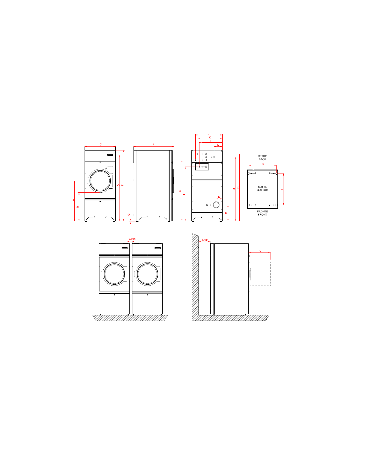
E100301X rev5 21/02/14
DRYERS 10 - 34
Page 33
E081101X rev5 21/02/14
32
[mm]
10 14 18 23 34
A
971 971 971 1061 1061
B
691 691 691 781 781
C
791 791 791 1022 1022
D
1610 1610 1610 1691 1691
E
1760 1760 1760 1932 1932
F
707 874 1051 918 1188
G
15÷20 15÷20 15÷20 15÷20 15÷20
H
1508 1508 1508 1496 1496
I
1302 1302 1302 1496 1496
J
622 622 622 921 921
K
576 576 576 685 685
L
563 563 563 921 921
M
208 208 208 327 327
N
157 157 157 193 193
P
422 422 422 422 422
Q
1576 1576 1576 1691 1691
R
1666 1666 1666 1776 1776
S
714 714 714 945 945
T
487 654 831 671 952
V
560 560 560 560 560
Wmin
10 10 10 10 10
Xmin
500 500 500 500 500
DRYERS 10 - 34
Page 34
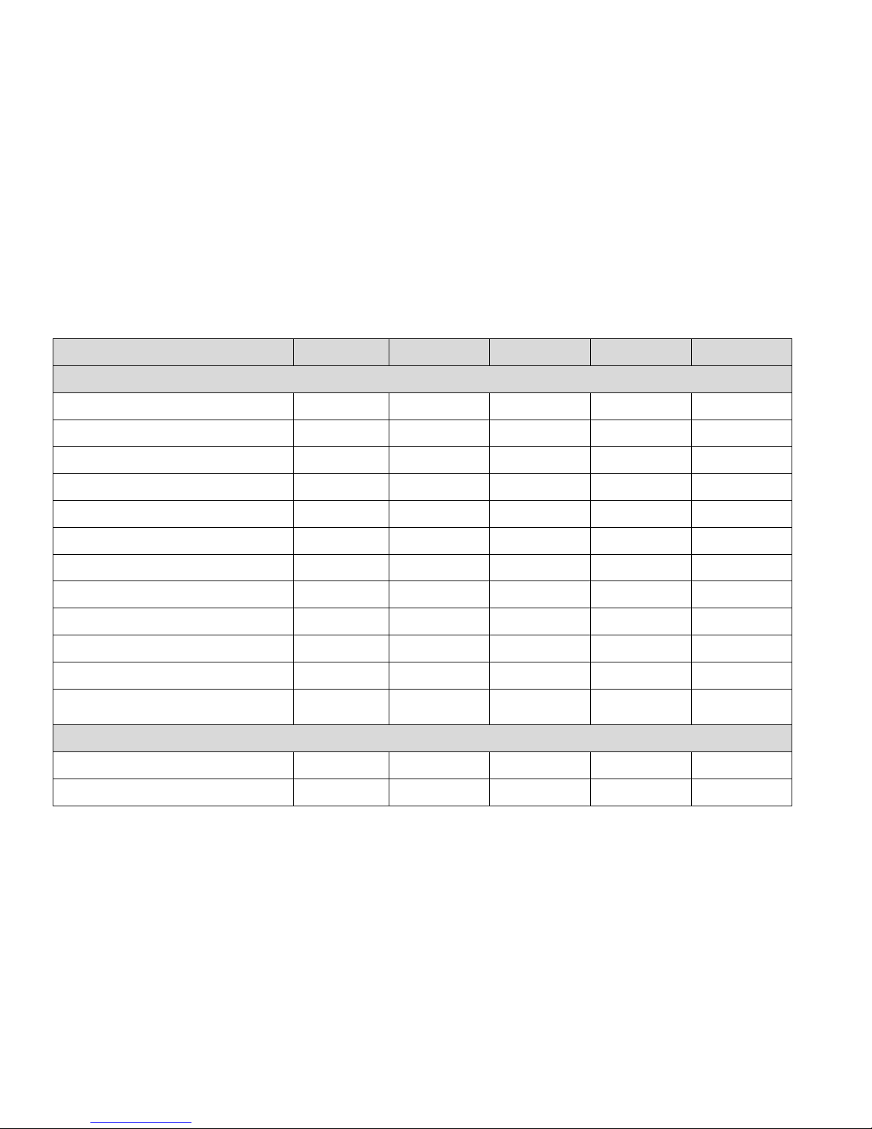
E100301X rev5 21/02/14
52. TEHCNICAL DATA 55-75
MODEL U.M. 55 55 T 75 75 T
MAIN FEATURES
CAPACITY 1/20 and 1/25 kg 55 / 43,5 55 / 43,5 75 / 60 75 / 60
REVERSING DRUM - SI SI SI SI
DRUM DIAMETER Ø mm 1202 1202 1202 1202
DRUM DEPTH mm 960 960 1310 1310
LOADING DIAMETER Ø mm 890 890 890 890
STANDARD SPEED rpm 25 25 25 25
NOISE dB(A) 74 74 74 74
LOSS AT SHELL % 15 15 15 15
AIR / BURN GAS EXHAUST (pos.6) Ø mm 300 300 300 300
AIR FLOW m3/h 1980 1980 1980 1980
MAX BACKPRESSURE mt 10 10 10 10
NET WEIGHT (electric / gas / steam) STD or
NET WEIGHT (electric / gas / steam) 1 WAY / 2
WAYS
kg 813 / 829 / 822
821 / 837 / 830
828 / 844 / 837
1135 / 1156 / 1147
1143 / 1164 / 1155
1150 / 1171 / 1162
STANDARD PACKAGE
WIDTH mm 1540 1540 1540 1540
DEPTH mm 1700 1700 2050 2050
Page 35
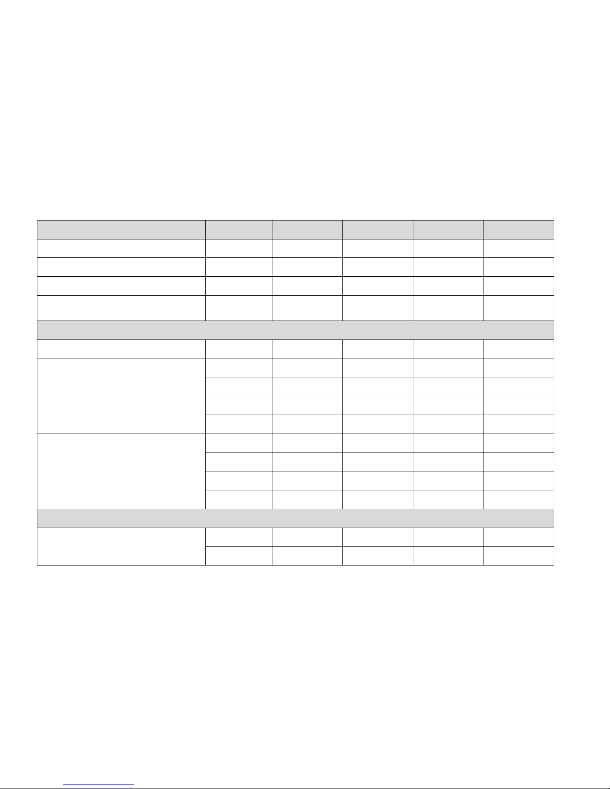
E100301X rev5 21/02/14
MODEL U.M. 55 55 T 75 75 T
HEIGHT WITH PALLET mm 2422 2422 2422 2422
HEIGHT WITHOUT PALLET (FOR CONTAINER) mm 2272 2272 2272 2272
VOLUME WITH PALLET / WITHOUT PALLET m3 6,3 / 5,9 6,3 / 5,9 7,6 / 7,1 7,6 / 7,1
GROSS WEIGHT (electric / gas / steam) STD or
GROSS WEIGHT (electric / gas / steam) 1 WAY /
2 WAYS
kg 882 / 898 / 891
889 / 905 / 898
897 / 913 / 906
1199 / 1220/ 1211
1206 / 1227 / 1218
1214 / 1235 / 1226
HEATING
ELECTRIC HEATING kW 58,5 58,5 97,5 97,5
STANDARD STEAM (pos. 2=IN; pos. 3=OUT)
TILTING STEAM (pos. 2T=IN; pos. 3T=OUT)
STEAM CONSUME (10bar)*
Ø IN 1 ¼” 1 ¼” 1 ½” 1 ½”
Ø OUT 1” 1” 1 ¼” 1 ¼”
bar 15 15 15 15
kg 71 71 97 97
STANDARD GAS (pos. 4)
TILTING GAS (pos. 4T)
GAS CONSUME*
kW 95 95 115 115
Ø IN 1 ¼” 1 ¼” 1 ¼” 1 ¼”
m3 (G20) 3,8 3,8 5,2 5,2
kg (GPL / GLP) 2,6 2,6 3,5 3,5
ELECTRIC ABSORPTION (pos. 1)
ELECTRIC HEATING
3ph380V-480V (+N) / 3ph220V-240V / 1ph230V
50/60Hz
kW 60,7 60,7 100,5 100,5
A 88 / 152 / - 88 / 152 / - 148 / 256 / - 148 / 256 / -
Page 36
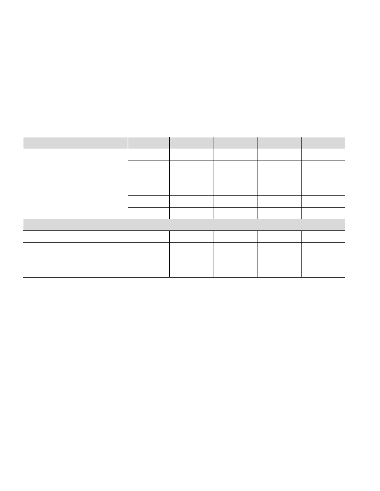
E100301X rev5 21/02/14
MODEL U.M. 55 55 T 75 75 T
CABLE SECTION
CONSUME*
mm
2
16 / 35/ - 16 / 35 / - 35 / 50 / - 35 / 50 / -
kWh 35,8 35,8 48,8 48,8
STEAM AND GAS HEATING
3ph380V-480V (+N) / 3ph220V-240V / 1ph230V
50/60Hz
CABLE SECTION
CONSUME*
kW 2,2 2,2 3 3
A 2,8 / 4,8 / 8,4 2,8 / 4,8 / 8,4 4 / 7 / - 4 / 7 / -
mm2 2,5 / 2,5 / 2,5 2,5 / 2,5 / 2,5 2,5 / 2,5 / 2,5 2,5 / 2,5 / 2,5
kWh 0,7 0,7 1 1
COMPRESSED AIR
COMPRESSED AIR IN (pos. 5) std configuration
steam heating
Ø mm 6 - 6 -
COMPRESSED AIR IN (pos. 5T) tilting
configuration
Ø mm - 12 - 12
COMPRESSED AIR CONSUME (electric / gas
machine)
l/h - 100 - 100
COMPRESSED AIR CONSUME (steam
machine)
l/h 5 105 5 105
NOTE: in case of tilting configuartion, data refers to a 2 way tilting machine (laod and unload with tilting)
*Standard cycle: load at the nominal capacity using wet cotton (180gr/m
2
) with a 50% residual humidity for a 0% residual humidity output. 3’ cooling.
Page 37
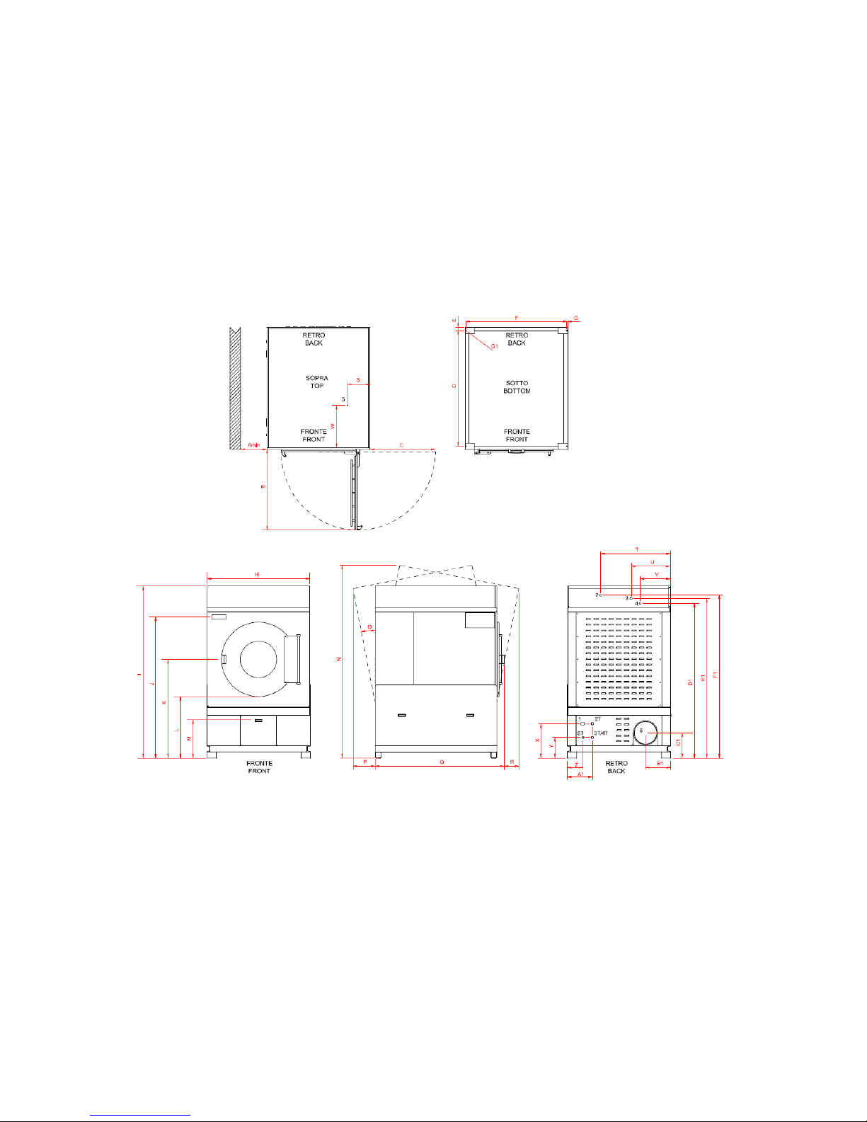
E100301X rev5 21/02/14
DRYERS 55 - 75
Page 38
E081101X rev5 21/02/14
37
[mm]
55 55 T 75 75 T
Amin
500 500 500 500
B
1063 1063 1063 1063
C
858 858 858 858
D
1520 1520 1870 1870
E
40 40 40 40
F
1330 1330 1340 1340
G
10 10 10 10
H
1360 1360 1360 1360
I
2260 2260 2260 2260
J
1850 1850 1850 1850
K
1295 1295 1295 1295
L
807 807 807 807
M
500 500 500 500
N
- 2516 - 2516
O
- 11° - 8°
P
- 296 - 229
Q
1700 1700 1930 1930
R
- 247 - 292
S
220 - 220 -
T
913 - 913 -
U
514 - 514 -
V
395 - 395 -
W
570 - 570 -
X
359 359 359 359
Y
- 270 - 270
Z
- 207 - 207
A1
- 331 - 331
B1
330 330 330 330
C1
330 330 330 330
D1
2032 - 2032 -
E1
2095 - 2095 -
F1
2139 - 2139 -
G1
Ø 13 Ø 13 Ø 13 Ø 13
DRYERS 55 - 75
Page 39
E081101X rev5 21/02/14
38
53. GAS PRESSURE
Only in case of gas heated dryers, please check
the nominal pressure data and the nozzle
dimension in the next tables.
I, UK, IE, ES
Type B22, II2H3+ CE 0085-AT0341
Max pressure in the flue: 150Pa
NATURAL GAS 2H (G20); PCI=34,02MJ/Nm
3
P
n
=20.
000Pa
P
max
=2500Pa; P
min
=1700Pa
Dryer
nozzles
[nr]
Ø nozzles
[mm]
10 2 2,90
14 2 2,90
18 2 2,90
23 3 2,70
34 4 2,70
55 4 4,05
75 4 5,00
LIQUID GAS 3+ (G30); PCI=45,65MJ/kg
P
n
=2800-3000/3700Pa
P
max
=3500/4500Pa; P
min
=2000/2500Pa
Dryer
nozzles
[nr]
Ø nozzles
[mm]
10 2 1,85
14 2 1,85
18 2 1,85
23 3 1,75
34 4 1,75
55 4 2,35
75 4 2,75
AT, CH
Type B22, II2H3+ CE 0085-AT0341
Max pressure in the flue: 150Pa
NATURAL GAS 2H (G20); PCI=34,02MJ/Nm
3
P
n
=2000Pa
P
max
=2500Pa; P
min
=1700Pa
Dryer
nozzles
[nr]
Ø nozzles
[mm]
10 2 2,90
14 2 2,90
18 2 2,90
23 3 2,70
34 4 2,70
55 4 4,05
75 4 5,00
LIQUID GAS 3B/P (G30); PCI=45,65MJ/kg
P
n
=2800-3000/3700Pa
P
max
=3500/4500Pa; P
min
=2000/2500Pa
Dryer
nozzles
[nr]
Ø nozzles
[mm]
10 2 1,85
14 2 1,85
18 2 1,85
23 3 1,75
34 4 1,75
55 4 2,35
75 4 2,75
F
Type B22, IIE+3+ CE 0085-AT0341
Max pressure in the flue: 150Pa
NATURAL GAS 2E+ (G20); PCI=34,02MJ/Nm
3
P
n
=2000Pa
P
max
=2500Pa; P
min
=1700Pa
Dryer
nozzles
[nr]
Ø nozzles
[mm]
10 2 2,90
14 2 2,90
18 2 2,90
23 3 2,70
34 4 2,70
55 4 4,05
75 4 5,00
LIQUID GAS 3+ (G30); PCI=45,65MJ/kg
P
n
=2800-3000/3700Pa
P
max
=3500/4500Pa; P
min
=2000/2500Pa
Dryer
nozzles
[nr]
Ø nozzles
[mm]
10 2 1,85
14 2 1,85
18 2 1,85
23 3 1,75
34 4 1,75
55 4 2,35
75 4 2,75
DE
Type B22, II2ELL3B/P CE 0085-AT0341
Max pressure in the flue: 150Pa
NATURAL GAS 2ELL (G20); PCI=34,02MJ/Nm
3
P
n
=2000Pa
P
max
=2500Pa; P
min
=1700Pa
Dryer
nozzles
[nr]
Ø nozzles
[mm]
10 2 2,90
14 2 2,90
18 2 2,90
23 3 2,70
34 4 2,70
55 4 4,05
75 4 5,00
Page 40
E100301X rev5 21/02/14
NATURAL GAS 2ELL (G25); PCI=29,30MJ/Nm
3
P
n
=1800Pa
P
max
=2500Pa; P
min
=2000Pa
Dryer
nozzles
[nr]
Ø nozzles
[mm]
10 2 3,20
14 2 3,20
18 2 3,20
23 3 3,00
34 4 3,00
55 4 4,50
75 4 5,50
LIQUID GAS 3B/P (G30); PCI=45,65MJ/kg
P
n
=2800-3000/3700Pa
P
max
=3500/4500Pa; P
min
=2000/2500Pa
Dryer
nozzles
[nr]
Ø nozzles
[mm]
10 2 1,65
14 2 1,65
18 2 1,65
23 3 1,50
34 4 1,50
55 4 2,35
75 4 2,75
 Loading...