

Page 1
•Diamond
AIRCRAFT
AIRPLANE FLIGHT MANUAL
DA62
I
J� 1q
Page O -
0
Page 2

DA 62 AFM Introduction
Intentionally left blank.
Page 0 - 0a Rev. 0
11-Jan-2019
Doc. # 11.01.05-E
Page 3

DA 62 AFM Introduction
FOREWORD
We congratulate you on the acquisition of your new DIAMOND DA 62.
Skillful operation of an airplane increases both safety and the enjoyment of flying. Please
take the time therefore, to familiarize yourself with your new DIAMOND DA 62.
This airplane may only be operated in accordance with the procedures and operating
limitations of this Airplane Flight Manual.
Before this airplane is operated for the first time, the pilot must familiarize himself with
the complete contents of this Airplane Flight Manual.
In the event that you have obtained your DIAMOND DA 62 second-hand, please let us
know your address, so that we can supply you with the publications necessary for the
safe operation of your airplane.
This document is protected by copyright. All associated rights, in particular those of
translation, reprinting, radio transmission, reproduction by photo-mechanical or similar
means and storing in data processing facilities, in whole or part, are reserved.
Copyright © by: DIAMOND AIRCRAFT INDUSTRIES INC.
1560 Crumlin Sideroad,
London, Ontario, Canada N5V 1S2
Phone. : +1 519 457 4000
E-Mail : [email protected]
Doc. # 11.01.05-E Rev. 0
11-Jan-2019 Page 0 - 1
Page 4

Introduction DA 62 AFM
0.1 APPROVAL
The content of approved chapters is approved by Transport Canada Civil Aviation.
0.2 RECORD OF REVISIONS
All revisions of this manual, with the exception of:
• Temporary Revisions,
• updates of the modification level (Section 1.1),
• updated mass and balance information (Section 6.3),
• updates of the Equipment Inventory (Section 6.5), and
• updates of the List of Supplements (Section 9.2)
must be recorded in the following table.
The new or amended text is indicated by a vertical black line at the left hand side of the
revised page, with the revision number and date appearing at the bottom of the page.
If pages are revised which contain information valid for your particular serial number
(modification level of the airplane, weighing data, Equipment Inventory, List of
Supplements), then this information must be transferred to the new pages in hand-writing.
Temporary Revisions, if applicable, are inserted behind the cover page of this manual.
Temporary Revisions are used to provide information on systems or equipment until the
next 'permanent' revision of the Airplane Flight Manual. When a 'permanent' revision
covers a Mandatory Design Change Advisory or Optional Design Change Advisory (MÄM
or OÄM), then the corresponding Temporary Revision is superseded. For example: If
Revision 1 covers OÄM 62-039, then the Temporary Revision TR OÄM-62-039 is
superseded by the 'permanent' Revision 1.
Page 0 - 2 Rev. 0
11-Jan-2019
Doc. # 11.01.05-E
Page 5

DA 62 AFM Introduction
Rev.
No.
Reason
Chapter
Page(s)
Date of
Revision
Approval No.
Approval
Date
Date
Inserted
Signature
Doc. # 11.01.05-E Rev. 0
11-Jan-2019
Page 0 - 3
Page 6

Introduction DA 62 AFM
0.3 LIST OF EFFECTIVE PAGES
Ch. Page Date
0 0-0 11-Jan-2019
0-0a 11-Jan-2019
0-1 11-Jan-2019
0-2 11-Jan-2019
0-3 11-Jan-2019
0-4 11-Jan-2019
0-5 11-Jan-2019
0-6 11-Jan-2019
0-7 11-Jan-2019
0-8 11-Jan-2019
0-9 11-Jan-2019
0-10 11-Jan-2019
0-11 11-Jan-2019
0-12 11-Jan-2019
Ch. Page Date
1 1-1 11-Jan-2019
1-2 11-Jan-2019
1-3 11-Jan-2019
1-4 11-Jan-2019
1-5 11-Jan-2019
1-6 11-Jan-2019
1-7 11-Jan-2019
1-8 11-Jan-2019
1-9 11-Jan-2019
1-10 11-Jan-2019
1-11 11-Jan-2019
1-12 11-Jan-2019
1-13 11-Jan-2019
1-14 11-Jan-2019
0-13 11-Jan-2019
0-14 11-Jan-2019
0-15 11-Jan-2019
Page 0 - 4 Rev. 0
11-Jan-2019
1-15 11-Jan-2019
1-16 11-Jan-2019
1-17 11-Jan-2019
1-18 11-Jan-2019
1-19 11-Jan-2019
1-20 11-Jan-2019
1-21 11-Jan-2019
1-22 11-Jan-2019
Doc. # 11.01.05-E
Page 7

DA 62 AFM Introduction
Ch. Page Date
2 DOT-appr. 2-1 11-Jan-2019
DOT-appr. 2-2 11-Jan-2019
DOT-appr. 2-3 11-Jan-2019
DOT-appr. 2-4 11-Jan-2019
DOT-appr. 2-5 11-Jan-2019
DOT-appr. 2-6 11-Jan-2019
DOT-appr. 2-7 11-Jan-2019
DOT-appr. 2-8 11-Jan-2019
DOT-appr. 2-9 11-Jan-2019
DOT-appr. 2-10 11-Jan-2019
DOT-appr. 2-11 11-Jan-2019
DOT-appr. 2-12 11-Jan-2019
DOT-appr. 2-13 11-Jan-2019
DOT-appr. 2-14 11-Jan-2019
Ch. Page Date
2 DOT-appr. 2-28 11-Jan-2019
DOT-appr. 2-29 11-Jan-2019
DOT-appr. 2-30 11-Jan-2019
DOT-appr. 2-31 11-Jan-2019
DOT-appr. 2-32 11-Jan-2019
DOT-appr. 2-33 11-Jan-2019
DOT-appr. 2-34 11-Jan-2019
DOT-appr. 2-35 11-Jan-2019
DOT-appr. 2-36 11-Jan-2019
DOT-appr. 2-37 11-Jan-2019
DOT-appr. 2-38 11-Jan-2019
DOT-appr. 2-39 11-Jan-2019
DOT-appr. 2-40 11-Jan-2019
DOT-appr. 2-41 11-Jan-2019
DOT-appr. 2-15 11-Jan-2019
DOT-appr. 2-16 11-Jan-2019
DOT-appr. 2-17 11-Jan-2019
DOT-appr. 2-18 11-Jan-2019
DOT-appr. 2-19 11-Jan-2019
DOT-appr. 2-20 11-Jan-2019
DOT-appr. 2-21 11-Jan-2019
DOT-appr. 2-22 11-Jan-2019
DOT-appr. 2-23 11-Jan-2019
DOT-appr. 2-24 11-Jan-2019
DOT-appr. 2-25 11-Jan-2019
DOT-appr. 2-26 11-Jan-2019
DOT-appr. 2-27 11-Jan-2019
DOT-appr. 2-42 11-Jan-2019
DOT-appr. 2-43 11-Jan-2019
DOT-appr. 2-44 11-Jan-2019
Doc. # 11.01.05-E Rev. 0
11-Jan-2019
Page 0 - 5
Page 8

Introduction DA 62 AFM
Ch. Page Date
3 3-1 11-Jan-2019
3-2 11-Jan-2019
3-3 11-Jan-2019
3-4 11-Jan-2019
3-5 11-Jan-2019
3-6 11-Jan-2019
3-7 11-Jan-2019
3-8 11-Jan-2019
3-9 11-Jan-2019
3-10 11-Jan-2019
3-11 11-Jan-2019
3-12 11-Jan-2019
3-13 11-Jan-2019
3-14 11-Jan-2019
Ch. Page Date
3 3-28 11-Jan-2019
3-29 11-Jan-2019
3-30 11-Jan-2019
3-31 11-Jan-2019
3-32 11-Jan-2019
3-33 11-Jan-2019
3-34 11-Jan-2019
3-35 11-Jan-2019
3-36 11-Jan-2019
3-37 11-Jan-2019
3-38 11-Jan-2019
3-39 11-Jan-2019
3-40 11-Jan-2019
3-41 11-Jan-2019
3-15 11-Jan-2019
3-16 11-Jan-2019
3-17 11-Jan-2019
3-18 11-Jan-2019
3-19 11-Jan-2019
3-20 11-Jan-2019
3-21 11-Jan-2019
3-22 11-Jan-2019
3-23 11-Jan-2019
3-24 11-Jan-2019
3-25 11-Jan-2019
3-26 11-Jan-2019
3-27 11-Jan-2019
3-42 11-Jan-2019
3-43 11-Jan-2019
3-44 11-Jan-2019
3-45 11-Jan-2019
3-46 11-Jan-2019
3-47 11-Jan-2019
3-48 11-Jan-2019
3-49 11-Jan-2019
3-50 11-Jan-2019
3-51 11-Jan-2019
3-52 11-Jan-2019
3-53 11-Jan-2019
3-54 11-Jan-2019
Page 0 - 6 Rev. 0
11-Jan-2019
Doc. # 11.01.05-E
Page 9

DA 62 AFM Introduction
Ch. Page Date
3 3-55 11-Jan-2019
3-56 11-Jan-2019
3-57 11-Jan-2019
3-58 11-Jan-2019
3-59 11-Jan-2019
3-60 11-Jan-2019
3-61 11-Jan-2019
3-62 11-Jan-2019
3-63 11-Jan-2019
3-64 11-Jan-2019
3-65 11-Jan-2019
3-66 11-Jan-2019
3-67 11-Jan-2019
3-68 11-Jan-2019
Ch. Page Date
4A 4A-1 11-Jan-2019
4A-2 11-Jan-2019
4A-3 11-Jan-2019
4A-4 11-Jan-2019
4A-5 11-Jan-2019
4A-6 11-Jan-2019
4A-7 11-Jan-2019
4A-8 11-Jan-2019
4A-9 11-Jan-2019
4A-10 11-Jan-2019
4A-11 11-Jan-2019
4A-12 11-Jan-2019
4A-13 11-Jan-2019
4A-14 11-Jan-2019
3-69 11-Jan-2019
3-70 11-Jan-2019
3-71 11-Jan-2019
3-72 11-Jan-2019
3-73 11-Jan-2019
3-74 11-Jan-2019
4A-15 11-Jan-2019
4A-16 11-Jan-2019
4A-17 11-Jan-2019
4A-18 11-Jan-2019
4A-19 11-Jan-2019
4A-20 11-Jan-2019
4A-21 11-Jan-2019
4A-22 11-Jan-2019
4A-23 11-Jan-2019
4A-24 11-Jan-2019
4A-25 11-Jan-2019
4A-26 11-Jan-2019
4A-27 11-Jan-2019
Doc. # 11.01.05-E Rev. 0
11-Jan-2019
Page 0 - 7
Page 10

Introduction DA 62 AFM
Ch. Page Date
4A 4A-28 11-Jan-2019
4A-29 11-Jan-2019
4A-30 11-Jan-2019
4A-31 11-Jan-2019
4A-32 11-Jan-2019
4A-33 11-Jan-2019
4A-34 11-Jan-2019
4A-35 11-Jan-2019
4A-36 11-Jan-2019
4A-37 11-Jan-2019
4A-38 11-Jan-2019
4A-39 11-Jan-2019
4A-40 11-Jan-2019
4A-41 11-Jan-2019
Ch. Page Date
4A 4A-55 11-Jan-2019
4A-56 11-Jan-2019
4A-57 11-Jan-2019
4A-58 11-Jan-2019
4A-59 11-Jan-2019
4A-60 11-Jan-2019
4A-61 11-Jan-2019
4A-62 11-Jan-2019
4A-63 11-Jan-2019
4A-64 11-Jan-2019
4A-65 11-Jan-2019
4A-66 11-Jan-2019
4A-67 11-Jan-2019
4A-68 11-Jan-2019
4A-42 11-Jan-2019
4A-43 11-Jan-2019
4A-44 11-Jan-2019
4A-45 11-Jan-2019
4A-46 11-Jan-2019
4A-47 11-Jan-2019
4A-48 11-Jan-2019
4A-49 11-Jan-2019
4A-50 11-Jan-2019
4A-51 11-Jan-2019
4A-52 11-Jan-2019
4A-53 11-Jan-2019
4A-54 11-Jan-2019
4A-69 11-Jan-2019
4A-70 11-Jan-2019
4A-71 11-Jan-2019
Page 0 - 8 Rev. 0
11-Jan-2019
Doc. # 11.01.05-E
Page 11

DA 62 AFM Introduction
Ch. Page Date
4B 4B-1 11-Jan-2019
4B-2 11-Jan-2019
4B-3 11-Jan-2019
4B-4 11-Jan-2019
4B-5 11-Jan-2019
4B-6 11-Jan-2019
4B-7 11-Jan-2019
4B-8 11-Jan-2019
4B-9 11-Jan-2019
4B-10 11-Jan-2019
4B-11 11-Jan-2019
4B-12 11-Jan-2019
4B-13 11-Jan-2019
4B-14 11-Jan-2019
Ch. Page Date
4B 4B-28 11-Jan-2019
4B-29 11-Jan-2019
4B-30 11-Jan-2019
4B-31 11-Jan-2019
4B-32 11-Jan-2019
4B-33 11-Jan-2019
4B-34 11-Jan-2019
4B-35 11-Jan-2019
4B-36 11-Jan-2019
4B-37 11-Jan-2019
4B-38 11-Jan-2019
4B-39 11-Jan-2019
4B-40 11-Jan-2019
4B-41 11-Jan-2019
4B-15 11-Jan-2019
4B-16 11-Jan-2019
4B-17 11-Jan-2019
4B-18 11-Jan-2019
4B-19 11-Jan-2019
4B-20 11-Jan-2019
4B-21 11-Jan-2019
4B-22 11-Jan-2019
4B-23 11-Jan-2019
4B-24 11-Jan-2019
4B-25 11-Jan-2019
4B-26 11-Jan-2019
4B-27 11-Jan-2019
4B-42 11-Jan-2019
4B-43 11-Jan-2019
Doc. # 11.01.05-E Rev. 0
11-Jan-2019
Page 0 - 9
Page 12

Introduction DA 62 AFM
Ch. Page Date
5 5-1 11-Jan-2019
5-2 11-Jan-2019
5-3 11-Jan-2019
5-4 11-Jan-2019
5-5 11-Jan-2019
5-6 11-Jan-2019
5-7 11-Jan-2019
5-8 11-Jan-2019
5-9 11-Jan-2019
5-10 11-Jan-2019
5-11 11-Jan-2019
5-12 11-Jan-2019
5-13 11-Jan-2019
5-14 11-Jan-2019
Ch. Page Date
5 5-28 11-Jan-2019
5-29 11-Jan-2019
5-30 11-Jan-2019
5-31 11-Jan-2019
5-32 11-Jan-2019
5-33 11-Jan-2019
5-34 11-Jan-2019
5-35 11-Jan-2019
5-36 11-Jan-2019
5-37 11-Jan-2019
5-38 11-Jan-2019
5-39 11-Jan-2019
5-40 11-Jan-2019
5-41 11-Jan-2019
5-15 11-Jan-2019
5-16 11-Jan-2019
5-17 11-Jan-2019
5-18 11-Jan-2019
5-19 11-Jan-2019
5-20 11-Jan-2019
5-21 11-Jan-2019
5-22 11-Jan-2019
5-23 11-Jan-2019
5-24 11-Jan-2019
5-25 11-Jan-2019
5-26 11-Jan-2019
5-27 11-Jan-2019
5-42 11-Jan-2019
5-43 11-Jan-2019
5-44 11-Jan-2019
5-45 11-Jan-2019
5-46 11-Jan-2019
5-47 11-Jan-2019
5-48 11-Jan-2019
5-49 11-Jan-2019
5-50 11-Jan-2019
5-51 11-Jan-2019
5-52 11-Jan-2019
5-53 11-Jan-2019
5-54 11-Jan-2019
Page 0 - 10 Rev. 0
11-Jan-2019
Doc. # 11.01.05-E
Page 13

DA 62 AFM Introduction
Ch. Page Date
5 5-55 11-Jan-2019
5-56 11-Jan-2019
5-57 11-Jan-2019
5-58 11-Jan-2019
5-59 11-Jan-2019
5-60 11-Jan-2019
5-61 11-Jan-2019
5-62 11-Jan-2019
5-63 11-Jan-2019
5-64 11-Jan-2019
5-65 11-Jan-2019
5-66 11-Jan-2019
5-67 11-Jan-2019
5-68 11-Jan-2019
Ch. Page Date
5 5-82 11-Jan-2019
5-83 11-Jan-2019
5-84 11-Jan-2019
5-85 11-Jan-2019
5-86 11-Jan-2019
5-87 11-Jan-2019
5-88 11-Jan-2019
5-89 11-Jan-2019
5-90 11-Jan-2019
5-91 11-Jan-2019
5-92 11-Jan-2019
5-69 11-Jan-2019
5-70 11-Jan-2019
5-71 11-Jan-2019
5-72 11-Jan-2019
5-73 11-Jan-2019
5-74 11-Jan-2019
5-75 11-Jan-2019
5-76 11-Jan-2019
5-77 11-Jan-2019
5-78 11-Jan-2019
5-79 11-Jan-2019
5-80 11-Jan-2019
5-81 11-Jan-2019
Doc. # 11.01.05-E Rev. 0
11-Jan-2019
Page 0 - 11
Page 14

Introduction DA 62 AFM
Ch. Page Date
6 6-1 11-Jan-2019
6-2 11-Jan-2019
6-3 11-Jan-2019
6-4 11-Jan-2019
6-5 11-Jan-2019
6-6 11-Jan-2019
6-7 11-Jan-2019
6-8 11-Jan-2019
6-9 11-Jan-2019
6-10 11-Jan-2019
6-11 11-Jan-2019
6-12 11-Jan-2019
6-13 11-Jan-2019
6-14 11-Jan-2019
6-15 11-Jan-2019
6-16 11-Jan-2019
6-17 11-Jan-2019
6-18 11-Jan-2019
6-19 11-Jan-2019
6-20 11-Jan-2019
6-21 11-Jan-2019
6-22 11-Jan-2019
6-23 11-Jan-2019
6-24 11-Jan-2019
6-25 11-Jan-2019
6-26 11-Jan-2019
6-27 11-Jan-2019
6-28 11-Jan-2019
Ch. Page Date
6 6-29 11-Jan-2019
Ch. Page Date
7 7-1 11-Jan-2019
7-2 11-Jan-2019
7-3 11-Jan-2019
7-4 11-Jan-2019
7-5 11-Jan-2019
7-6 11-Jan-2019
7-7 11-Jan-2019
7-8 11-Jan-2019
7-9 11-Jan-2019
7-10 11-Jan-2019
7-11 11-Jan-2019
7-12 11-Jan-2019
7-13 11-Jan-2019
7-14 11-Jan-2019
7-15 11-Jan-2019
7-16 11-Jan-2019
7-17 11-Jan-2019
7-18 11-Jan-2019
7-19 11-Jan-2019
7-20 11-Jan-2019
7-21 11-Jan-2019
7-22 11-Jan-2019
7-23 11-Jan-2019
7-24 11-Jan-2019
7-25 11-Jan-2019
Page 0 - 12 Rev. 0
11-Jan-2019
Doc. # 11.01.05-E
Page 15
DA 62 AFM Introduction
Ch. Page Date
7 7-26 11-Jan-2019
7-27 11-Jan-2019
7-28 11-Jan-2019
7-29 11-Jan-2019
7-30 11-Jan-2019
7-31 11-Jan-2019
7-32 11-Jan-2019
7-33 11-Jan-2019
7-34 11-Jan-2019
7-35 11-Jan-2019
7-36 11-Jan-2019
7-37 11-Jan-2019
7-38 11-Jan-2019
7-39 11-Jan-2019
Ch. Page Date
7 7-54 11-Jan-2019
7-55 11-Jan-2019
7-56 11-Jan-2019
7-57 11-Jan-2019
7-58 11-Jan-2019
7-59 11-Jan-2019
7-60 11-Jan-2019
7-61 11-Jan-2019
7-62 11-Jan-2019
7-63 11-Jan-2019
7-64 11-Jan-2019
7-65 11-Jan-2019
7-66 11-Jan-2019
7-67 11-Jan-2019
7-40 11-Jan-2019
7-41 11-Jan-2019
7-42 11-Jan-2019
7-43 11-Jan-2019
7-44 11-Jan-2019
7-45 11-Jan-2019
7-46 11-Jan-2019
7-47 11-Jan-2019
7-48 11-Jan-2019
7-49 11-Jan-2019
7-50 11-Jan-2019
7-51 11-Jan-2019
7-52 11-Jan-2019
7-53 11-Jan-2019
7-68 11-Jan-2019
7-69 11-Jan-2019
7-70 11-Jan-2019
7-71 11-Jan-2019
7-72 11-Jan-2019
7-73 11-Jan-2019
7-74 11-Jan-2019
7-75 11-Jan-2019
7-76 11-Jan-2019
7-77 11-Jan-2019
7-78 11-Jan-2019
7-79 11-Jan-2019
7-80 11-Jan-2019
7-81 11-Jan-2019
Doc. # 11.01.05-E Rev. 0
11-Jan-2019
Page 0 - 13
Page 16
Introduction DA 62 AFM
Ch. Page Date
7 7-82 11-Jan-2019
7-83 11-Jan-2019
7-84 11-Jan-2019
7-85 11-Jan-2019
7-86 11-Jan-2019
7-87 11-Jan-2019
7-88 11-Jan-2019
7-89 11-Jan-2019
7-90 11-Jan-2019
7-91 11-Jan-2019
7-92 11-Jan-2019
7-93 11-Jan-2019
7-94 11-Jan-2019
Ch. Page Date
8 8-1 11-Jan-2019
8-2 11-Jan-2019
8-3 11-Jan-2019
8-4 11-Jan-2019
8-5 11-Jan-2019
8-6 11-Jan-2019
8-7 11-Jan-2019
8-8 11-Jan-2019
8-9 11-Jan-2019
8-10 11-Jan-2019
8-11 11-Jan-2019
8-12 11-Jan-2019
8-13 11-Jan-2019
8-14 11-Jan-2019
8-15 11-Jan-2019
8-16 11-Jan-2019
Ch. Page Date
9 9-1 11-Jan-2019
9-2 11-Jan-2019
9-3 11-Jan-2019
9-4 11-Jan-2019
Page 0 - 14 Rev. 0
11-Jan-2019
Doc. # 11.01.05-E
Page 17

DA 62 AFM Introduction
TABLE OF CONTENTS
Chapter
GENERAL
(a non-approved chapter) . . . . . . . . . . . . . . . . . . . . . . . . . . . . . . . . . . . . . . . . 1
OPERATING LIMITATIONS
(an approved chapter). . . . . . . . . . . . . . . . . . . . . . . . . . . . . . . . . . . . . . . . . . . 2
EMERGENCY PROCEDURES
(a non-approved chapter) . . . . . . . . . . . . . . . . . . . . . . . . . . . . . . . . . . . . . . . . 3
NORMAL OPERATING PROCEDURES
(a non-approved chapter) . . . . . . . . . . . . . . . . . . . . . . . . . . . . . . . . . . . . . . . 4A
ABNORMAL OPERATING PROCEDURES
(a non-approved chapter) . . . . . . . . . . . . . . . . . . . . . . . . . . . . . . . . . . . . . . . 4B
PERFORMANCE
(a non-approved chapter) . . . . . . . . . . . . . . . . . . . . . . . . . . . . . . . . . . . . . . . . 5
MASS AND BALANCE / EQUIPMENT LIST
(a non-approved chapter) . . . . . . . . . . . . . . . . . . . . . . . . . . . . . . . . . . . . . . . . 6
DESCRIPTION OF THE AIRPLANE AND ITS SYSTEMS
(a non-approved chapter) . . . . . . . . . . . . . . . . . . . . . . . . . . . . . . . . . . . . . . . . 7
AIRPLANE HANDLING, CARE AND MAINTENANCE
(a non-approved chapter) . . . . . . . . . . . . . . . . . . . . . . . . . . . . . . . . . . . . . . . . 8
SUPPLEMENTS . . . . . . . . . . . . . . . . . . . . . . . . . . . . . . . . . . . . . . . . . . . . . . . . . . . . . . . . . . . . . . . . . . . 9
Doc. # 11.01.05-E Rev. 0
11-Jan-2019
Page 0 - 15
Page 18

DA 62 AFM General
CHAPTER 1
GENERAL
Page
1.1 INTRODUCTION . . . . . . . . . . . . . . . . . . . . . . . . . . . . . . . . . . . . . . . . 1-2
1.2 CERTIFICATION BASIS . . . . . . . . . . . . . . . . . . . . . . . . . . . . . . . . . . 1-4
1.3 WARNINGS, CAUTIONS AND NOTES . . . . . . . . . . . . . . . . . . . . . . 1-4
1.4 DIMENSIONS . . . . . . . . . . . . . . . . . . . . . . . . . . . . . . . . . . . . . . . . . . 1-5
1.5 DEFINITIONS AND ABBREVIATIONS . . . . . . . . . . . . . . . . . . . . . . . 1-7
1.6 UNITS OF MEASUREMENT . . . . . . . . . . . . . . . . . . . . . . . . . . . . . . 1-16
1.6.1 CONVERSION FACTORS. . . . . . . . . . . . . . . . . . . . . . . . . . . 1-16
1.6.2 CONVERSION CHART LITERS / US GALLONS . . . . . . . . . 1-18
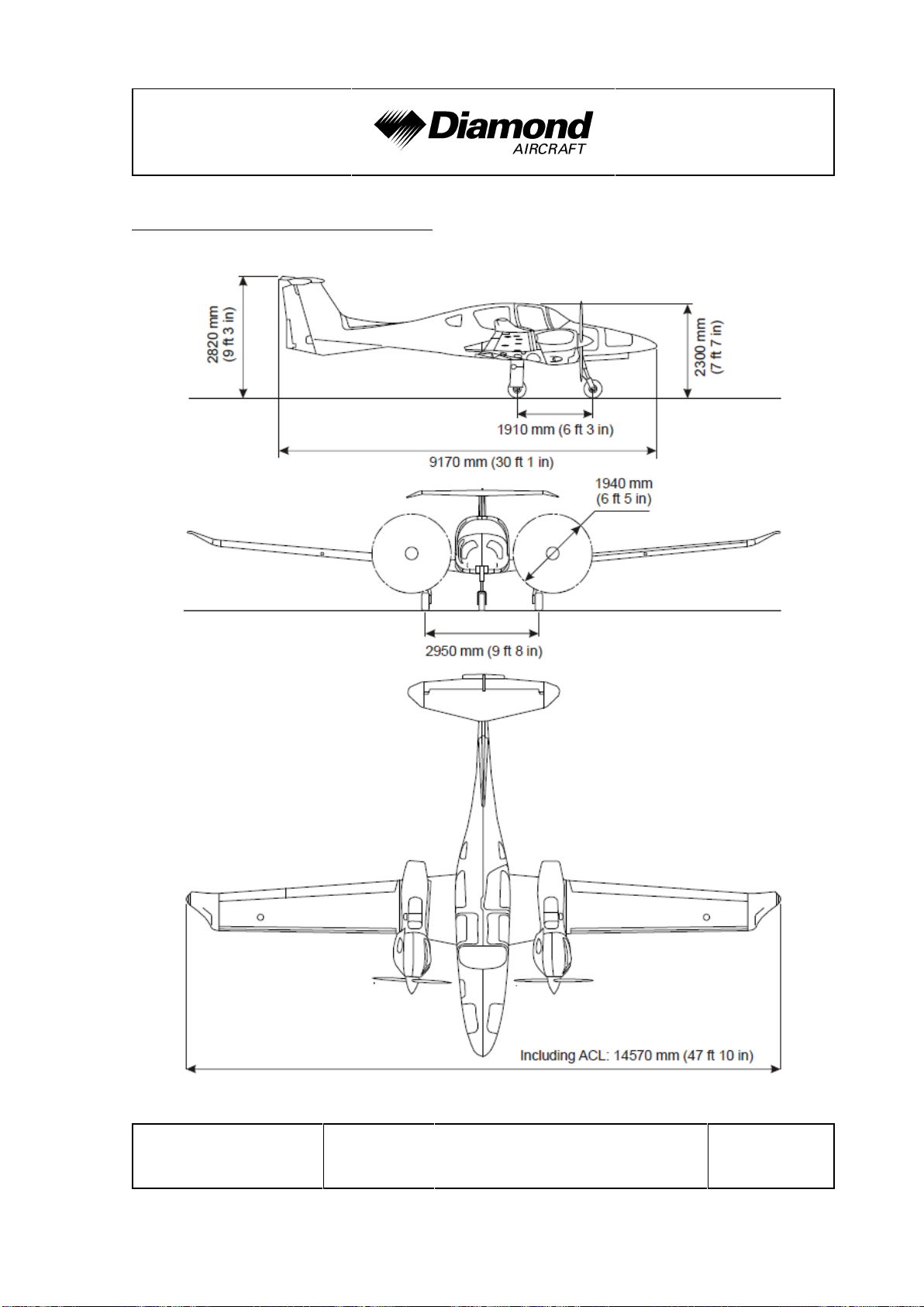
1.7 THREE-VIEW DRAWING . . . . . . . . . . . . . . . . . . . . . . . . . . . . . . . . 1-19
1.8 G1000 AVIONICS SYSTEM . . . . . . . . . . . . . . . . . . . . . . . . . . . . . . 1-20
1.9 SOURCE DOCUMENTATION. . . . . . . . . . . . . . . . . . . . . . . . . . . . . 1-21
1.9.1 ENGINE . . . . . . . . . . . . . . . . . . . . . . . . . . . . . . . . . . . . . . . . . 1-21
1.9.2 PROPELLER . . . . . . . . . . . . . . . . . . . . . . . . . . . . . . . . . . . . . 1-21
1.9.3 AVIONICS SYSTEM . . . . . . . . . . . . . . . . . . . . . . . . . . . . . . . 1-22
Doc. No. 11.01.05-E Rev. 0 11-Jan-2019 Page 1 - 1
Page 19

General DA 62 AFM
1.1 INTRODUCTION
This Airplane Flight Manual has been prepared in order to provide pilots and instructors
with all the information required for the safe and efficient operation of the airplane.
The Airplane Flight Manual includes all the data which must be made available to the
pilot according to the AWM 523 requirement. Beyond this, it contains further data and
operating instructions which, in the manufacturer’s opinion, could be of value to the pilot.
Equipment and modification level (design details) of the airplane may vary from serial
number to serial number. Therefore, some of the information contained in this manual
is applicable depending on the respective equipment and modification level. The exact
equipment of your serial number is recorded in the Equipment Inventory in Section 6.5.
The modification level is recorded in the following table (as far as necessary for this
manual).
Modification Source Installed
MTOM 2300 kg/5071 lb MÄM 62-001 9 yes 9 no
Maximum Zero Fuel Mass
2200 kg (4850 lb)
Engine Software
VC33_2P_05_19*
Garmin Hard- and Software
Upgrade I (Garmin G1000 NXi)
Auxiliary Fuel Tanks OÄM 62-001 9 yes 9 no
Continuous Flow Oxygen System
(77 cuft cylinder)
Garmin GWX 70 Weather Radar OÄM 62-009 9 yes 9 no
Avidyne TAS 600 Series OÄM 62-011 9 yes 9 no
MTOM 1999 kg/4407 lb OÄM 62-018 9 yes 9 no
MÄM 62-063 9 yes 9 no
MÄM 62-168 9 yes 9 no
MÄM 62-254 9 yes 9 no
OÄM 62-004 9 yes 9 no
7 Seated Configuration OÄM 62-019 9 yes 9 no
Page 1 - 2 Rev. 0 11-Jan-2019 Doc. No. 11.01.05-E
Page 20

DA 62 AFM General
Modification Source Installed
WX-500 Storm Scope OÄM 62-021 9 yes 9 no
Continuous Flow Oxygen
System (50 cuft cylinder)
Removal of Unfeathering
Akkumulator
Heated Static Ports OÄM 62-037 9 yes 9 no
On Top Exhaust System OÄM 62-038 9 yes 9 no
28V Power Outlet Option OÄM 62-1002 9 yes 9 no
* Or later approved software
This Airplane Flight Manual must be kept on board the airplane at all times. Its designated
place is the side bag of the forward left seat. The designated place for the Garmin G1000
Cockpit Reference Guide is the bag on the rear side of the forward right seat.
OÄM 62-028 9 yes 9 no
OÄM 62-030 9 yes 9 no
CAUTION
The DA 62 is a twin engine airplane. When the operating
limitations and maintenance requirements are complied with,
it has the high degree of reliability which is required by the
certification basis. Nevertheless, an engine failure is not
completely impossible. For this reason it is highly
recommended for flights during the night, on top, under IMC,
or above terrain which is unsuitable for a landing, to select
flight times and flight routes such that reduced performance
in case of single engine operation does not constitute a risk.
Doc. No. 11.01.05-E Rev. 0 11-Jan-2019 Page 1 - 3
Page 21

General DA 62 AFM
1.2 CERTIFICATION BASIS
The DA 62 has been approved by Transport Canada in accordance with the Canadian
Airworthiness Manual (AWM) Chapter 523, Type Certificate No. A-273
Category of Airworthiness: NORMAL
1.3 WARNINGS, CAUTIONS AND NOTES
Special statements in the Airplane Flight Manual concerning the safety or operation of
the airplane are highlighted by being prefixed by one of the following terms:
WARNING
means that the non-observation of the corresponding
procedure leads to an immediate or important
degradation in flight safety.
CAUTION
means that the non-observation of the corresponding
procedure leads to a minor or to a more or less long term
degradation in flight safety.
NOTE
draws the attention to any special item not directly related
to safety but which is important or unusual.
Page 1 - 4 Rev. 0 11-Jan-2019 Doc. No. 11.01.05-E
Page 22

DA 62 AFM General
1.4 DIMENSIONS
NOTE
All dimensions shown below are approximate.
Overall Dimensions
Span : 14.57 m 47 ft 10 in
Length : 9.17 m 30 ft 1 in
Height : 2.82 m 9 ft 3 in
Wing
Airfoil : Wortmann FX 63-137/20 - W4
Wing Area : 17.10 m² 184.1 sq.ft.
Mean aerodynamic chord : 1.247 m 4 ft 1 in
Aspect ratio : 12.8
Dihedral : 5.2°
Leading edge sweep : 1°
Aileron
Area (total, left + right) : 0.65 m² 7 sq.ft.
Doc. No. 11.01.05-E Rev. 0 11-Jan-2019 Page 1 - 5
Page 23

General DA 62 AFM
Wing Flaps
Area (total, left + right) : 2.16 m² 23.25 sq.ft.
Horizontal Tail
Area : 2.91 m
2
31.32 sq.ft.
Elevator area : 0.82 m² 8.83 sq.ft.
Angle of incidence : -2° relative to longitudinal axis of airplane
Vertical Tail
Area : 2.31 m² 24.86 sq.ft.
Rudder area : 0.74 m² 7.97 sq.ft.
Landing Gear
Track : 2.95 m (9 ft 8 in)
Wheelbase : 1.91 m (6 ft 3 in)
Nose wheel : 6.00-6, for details refer to AMM
Main wheel : 6.00-6, for details refer to AMM
Page 1 - 6 Rev. 0 11-Jan-2019 Doc. No. 11.01.05-E
Page 24

DA 62 AFM General
1.5 DEFINITIONS AND ABBREVIATIONS
(a) Airspeeds
CAS: Calibrated Airspeed. Indicated airspeed, corrected for installation and instrument
errors. CAS equals TAS at standard atmospheric conditions (ISA) at MSL.
IAS: Indicated Airspeed as shown on an airspeed indicator.
KCAS: CAS in knots.
KIAS: IAS in knots.
TAS: True Airspeed. The speed of the airplane relative to the air. TAS is CAS
corrected for errors due to altitude and temperature.
vO: Operating Maneuvering Speed. Full or abrupt control surface movement is not
permissible above this speed.
vFE: Maximum Flaps Extended Speed. This speed must not be exceeded with the
given flap setting.
vLE: Maximum Landing Gear Extended Speed. This speed may not be exceeded
if the landing gear is extended.
v
: Maximum Landing Gear Operating Speed for Extension. This speed may not
LOE
be exceeded during the extension of the landing gear.
v
: Maximum Landing Gear Operating Speed for Retraction. This speed may not
LOR
be exceeded during the retraction of the landing gear.
v
: Minimum Control Speed - Airborne. Minimum speed necessary to be able to
MCA
control the airplane in case of one engine inoperative.
v
: Never Exceed Speed in smooth air. This speed must not be exceeded in any
NE
operation.
Doc. No. 11.01.05-E Rev. 0 11-Jan-2019 Page 1 - 7
Page 25

General DA 62 AFM
vNO: Maximum Structural Cruising Speed. This speed may be exceeded only in
smooth air, and then only with caution.
v
: Rotation Speed.
R
v
: Stalling Speed, or the minimum continuous speed at which the airplane is still
S
controllable in the given configuration.
vS0: Stalling Speed, or the minimum continuous speed at which the airplane is still
controllable in the landing configuration.
vS1: Stalling Speed, or the minimum continuous speed at which the airplane is still
controllable with flaps and landing gear retracted.
v
: Minimum Control Speed for Schooling. Minimum speed necessary in case of
SSE
one engine intentionally inoperative/idle (training purposes).
vx: Best Angle-of-Climb Speed.
vy: Best Rate-of-Climb Speed.
v
: Best Rate of-Climb Speed for one engine inoperative.
YSE
v
: Speed at 50 ft above take-off surface.
50ft
(b) Meteorological Terms
ISA: International Standard Atmosphere. Conditions at which air is identified
as an ideal dry gas. The temperature at mean sea level is 15 °C (59 °F),
air pressure at MSL is 1013.25 hPa (29.92 inHg); the temperature
gradient up to the altitude at which the temperature reaches -56.5 °C
(-69.7 °F) is -0.0065 °C/m (-0.00357 °F/ft), and above this 0 °C/m (0
°F/ft).
MSL: Mean Sea Level.
OAT: Outside Air Temperature.
Page 1 - 8 Rev. 0 11-Jan-2019 Doc. No. 11.01.05-E
Page 26

DA 62 AFM General
QNH: Theoretical atmospheric pressure at MSL, calculated from the elevation
of the of the measuring point above MSL, and the actual atmospheric
pressure at the measuring point.
Density Altitude:
Altitude in ISA conditions at which the air density is equal to the current
air density.
Indicated Pressure Altitude:
Altitude reading with altimeter set to 1013.25 hPa (29.92 inHg).
Pressure Altitude:
Altitude indicated by a barometric altimeter, which is set to 1013.25 hPa
(29.92 inHg). The Pressure Altitude is the Indicated Pressure Altitude
corrected for installation and instrument errors.
In this Airplane Flight Manual, altimeter instrument errors are regarded
as zero.
Wind: The wind speeds which are shown as variables in the diagrams and
tables in this manual should be regarded as headwind or tailwind
components of the measured wind.
(c) Flight Performance and Flight Planning
AGL: Above Ground Level.
Demonstrated Crosswind Component:
The speed of the crosswind component at which adequate
maneuverability for take-off and landing has been demonstrated during
type certification.
Doc. No. 11.01.05-E Rev. 0 11-Jan-2019 Page 1 - 9
Page 27

General DA 62 AFM
MET: Weather, weather advice.
NAV: Navigation, route planning.
RoC: Rate of Climb.
(d) Mass and Balance
CG: Center of Gravity, also called 'center of mass'. Imaginary point in which
the airplane mass is assumed to be concentrated for mass and balance
calculations. Its distance from the Datum Plane is equal to the Center
of Gravity Moment Arm.
Center of Gravity Moment Arm:
The Moment Arm which is obtained if one divides the sum of the
individual moments of the airplane by its total mass.
Center of Gravity Limits:
The Center of Gravity range within which the airplane, at a given mass,
must be operated.
DP: Datum Plane; an imaginary vertical plane from which all horizontal
distances for center of gravity calculations are measured.
Empty Mass: The mass of the airplane including unusable fuel, all operating fluids and
the maximum quantity of oil.
Maximum Take-off Mass:
The maximum permissible mass for take-off.
Page 1 - 10 Rev. 0 11-Jan-2019 Doc. No. 11.01.05-E
Page 28

DA 62 AFM General
Maximum Landing Mass:
The highest mass for landing conditions at the maximum descent velocity.
This velocity was used in the strength calculations to determine the
landing gear loads during a particularly hard landing.
Moment Arm: The horizontal distance from the Datum Plane to the Center of Gravity
of a component.
Moment: The mass of a component multiplied by its moment arm.
Usable fuel: The quantity of fuel available for flight planning.
Unusable fuel: The quantity of fuel remaining in the tank which cannot be used for flight.
Useful load: The difference between take-off mass and empty mass.
(e) Engine
EECU: Electr. Engine Control Unit
RPM: Revolutions per minute (rotational speed of the propeller)
Engine starting fuel temperature:
Above this fuel temperature, the engine may be started.
Take-off fuel temperature:
Above this fuel temperature, take-off power setting is permitted.
OEI: One engine inoperative
Doc. No. 11.01.05-E Rev. 0 11-Jan-2019 Page 1 - 11
Page 29

General DA 62 AFM
(f) Designation of the Circuit Breakers on the Instrument Panel
LH MAIN BUS:
COM1 COM Radio No. 1
GPS/NAV1 Global Positioning System and NAV Receiver No. 1
XPDR Transponder
ENG INST Engine Instruments
PITOT Pitot Heating System
DE-ICE De-Icing System
TAXI/MAP/ACL Taxi-, Map-, Anti Collision Light
PFD Primary Flight Display
ADC Air Data Computer
AHRS Attitude Heading Reference System
GEAR WRN Landing Gear Annunciation
GEAR Landing Gear Control
AUX PUMPS Aux Fuel Pumps
RH MAIN BUS:
MFD Multi Function Display
SAM Standby Altitude Module
STALL WRN Stall Warning System
FLAP Flap System
LDG LT/START Landing Light/Start
NAV LT/FLOOD Navigation (Position) Light, Flood Light
AV/GDU/FAN Avionic-, GDU-Cooling Fans
AVIONIC BUS Avionic Bus
AV CONT Avionic Control
INST LT Instrument Light
STATIC HT/PEDALS Static Heating System/Adjustable Rudder Pedals
Page 1 - 12 Rev. 0 11-Jan-2019 Doc. No. 11.01.05-E
Page 30

DA 62 AFM General
AVIONICS BUS:
COM2 COM Radio No. 2
GPS/NAV2 Global Positioning System and NAV Receiver No. 2
AUDIO Audio Panel
AFCS/ESP/USP Auto Pilot System
TWX Lightning Detection System
ADF Automatic Direction Finder
DME Distance Measuring Equipment
Wx RDR Weather Radar
TAS Traffic Advisory System
DATA LINK Data Link System
IRIDIUM Satellite Receiver
EVS Enhanced Vision System
GCU/FLT STRM Control Unit (Keypad)/Flight Stream
LH ENG ECU BUS:
ECU BUS LH ECU Bus
ECU B LH ECU B
ECU A LH ECU A
LH BUS:
ALT.LH LH Alternator
BATT Battery
LH ENGINE:
FUEL PUMP A LH ECU A Fuel Pump
FUEL PUMP B LH ECU B Fuel Pump
Doc. No. 11.01.05-E Rev. 0 11-Jan-2019 Page 1 - 13
Page 31

General DA 62 AFM
RH ENG ECU BUS:
ECU BUS RH ECU Bus
ECU B RH ECU B
ECU A RH ECU A
RH BUS:
ALT.RH RH Alternator
BATT Battery
RH ENGINE:
FUEL PUMP A RH ECU A Fuel Pump
FUEL PUMP B RH ECU B Fuel Pump
(g) Equipment
ELT: Emergency Locator Transmitter
(h) Design Change Advisories
MÄM: Mandatory Design Change Advisory
OÄM: Optional Design Change Advisory
VÄM: Variant Design Change Advisory
Page 1 - 14 Rev. 0 11-Jan-2019 Doc. No. 11.01.05-E
Page 32

DA 62 AFM General
(i) Miscellaneous
AFM: Airplane Flight Manual
AMM: Airplane Maintenance Manual
ATC: Air Traffic Control
AWM: Airworthiness Manual
CAR: Canadian Airworthiness Regulation
CFRP: Carbon Fiber Reinforced Plastic
DOT: Department of Transport
EASA: European Aviation Safety Agency
EPU: External Power Unit
GIA: Garmin Integrated Avionics
GFRP: Glass Fiber Reinforced Plastic
GPS: Global Positioning System
IFR: Instrument Flight Rules
JC/VP: Joint Certification/Validation Procedure
PCA: Primary Certification Authority
TCCA: Transport Canada Civil Aviation
VFR: Visual Flight Rules
Doc. No. 11.01.05-E Rev. 0 11-Jan-2019 Page 1 - 15
Page 33

General DA 62 AFM
1.6 UNITS OF MEASUREMENT
1.6.1 CONVERSION FACTORS
Dimension SI Units US Units Conversion
Length
Volume
Speed
Speed of
rotation
Mass [kg] kilograms [lb] pounds [kg] x 2.2046 = [lb]
[mm] millimeters
[m] meters
[km] kilometers
[l] liters
[ml] milliliter
[km/h] kilometers
per hour
[m/s] meters per
second
[RPM] revolutions per minute --
[in] inches
[ft] feet
[NM] nautical
miles
[US gal] US gallons
[qts] US quarts
[oz] ounce
[kts] knots
[mph] miles per
hour
[fpm] feet per
minute
[mm] / 25.4 = [in]
[m] / 0.3048 = [ft]
[km] / 1.852 = [NM]
[l] / 3.7854 = [US gal]
[l] / 0.9464 = [qts]
[ml] x 0.033814 = [oz]
[km/h] / 1.852 = [kts]
[km/h] / 1.609 = [mph]
[m/s] x 196.85 = [fpm]
[fpm] / 196.85 = [m/s]
Force,
weight
Pressure [hPa] hecto-
Temperature
Page 1 - 16 Rev. 0 11-Jan-2019 Doc. No. 11.01.05-E
[N] Newtons
pascals
[mbar] millibars
[bar] bars
[°C] degrees
Celsius
[lbf] pounds
force
[inHg] inches of
mercury
[psi] pounds per
square inch
[°F] degrees
Fahrenheit
[N] x 0.2248 = [lbf]
[hPa] = [mbar]
[hPa] / 33.86 = [inHg]
[bar] x 14.504 = [psi]
[°C]x1.8 + 32 = [°F]
([°F] - 32)/1.8 = [°C]
Page 34

DA 62 AFM General
Dimension SI Units US Units Conversion
Intensity of
electric
current
Electric
charge
(battery
capacity)
[A] ampères --
[Ah] ampère-hours --
Electric
potential
Time [sec] seconds --
[V] volts --
Doc. No. 11.01.05-E Rev. 0 11-Jan-2019 Page 1 - 17
Page 35
General DA 62 AFM
1.6.2 CONVERSION CHART LITERS / US GALLONS
Liters US Gallons US Gallons Liters
5 1.3 1 3.8
10 2.6 2 7.6
15 4.0 4 15.1
20 5.3 6 22.7
25 6.6 8 30.3
30 7.9 10 37.9
35 9.2 12 45.4
40 10.6 14 53.0
45 11.9 16 60.6
50 13.2 18 68.1
60 15.9 20 75.7
70 18.5 22 83.3
80 21.1 24 90.9
90 23.8 26 98.4
100 26.4 28 106.0
110 29.1 30 113.6
120 31.7 32 121.1
130 34.3 34 128.7
140 37.0 36 136.3
150 39.6 38 143.8
160 42.3 40 151.4
170 44.9 45 170.3
180 47.6 50 189.3
Page 1 - 18 Rev. 0 11-Jan-2019 Doc. No. 11.01.05-E
Page 36
DA 62 AFM General
1.7 THREE-VIEW DRAWING
Doc. No. 11.01.05-E Rev. 0 11-Jan-2019 Page 1 - 19
Page 37

General DA 62 AFM
1.8 G1000 AVIONICS SYSTEM
1. The G1000 Integrated Avionics System is a fully integrated flight, engine,
communication, navigation and surveillance instrumentation system. The system
consists of a Primary Flight Display (PFD), Multi-Function Display (MFD), audio panel,
Air Data Computer (ADC), Attitude and Heading Reference System (AHRS), engine
sensors and processing unit (GEA), and integrated avionics (GIA) containing VHF
communications, VHF navigation, and GPS (Global Positioning System).
2. The primary function of the PFD is to provide attitude, heading, air data, navigation,
and alerting information to the pilot. The PFD may also be used for flight planning.
The primary function of the MFD is to provide engine information, mapping, terrain
information, autopilot operation, and for flight planning. The audio panel is used for
selection of radios for transmitting and listening, intercom functions, and marker beacon
functions.
3. The primary function of the VHF Communication portion of the G1000 is to enable
external radio communication. The primary function of the VOR/ILS Receiver portion
of the equipment is to receive and demodulate VOR, Localizer, and Glide Slope
signals. The primary function of the GPS portion of the system is to acquire signals
from the GPS satellites, recover orbital data, make range and Doppler measurements,
and process this information in real-time to obtain the user's position, velocity, and
time.
4. If the Garmin GWX 70 weather radar system is installed, it can be used to aid the pilot
in avoiding thunderstorms and associated turbulence or for ground mapping. The
GWX 70 shall be used to avoid severe weather and not for penetrating severe weather.
Pulse type weather radar systems like the GWX 70 detect precipitation only, not clouds
or turbulence. The display may indicate clear areas between intense returns, but this
does not necessarily mean it is safe to fly between them. As installed on the DA 62,
the Garmin GWX 70 has a demonstrated range of 160 nautical miles. Refer to Garmin
G1000 Pilot’s Guide for the DA 62, P/N 190-01895-( ) for Garmin G1000 or
P/N 190-01904-( ) for G1000 NXi in the latest effective issue for further information.
Page 1 - 20 Rev. 0 11-Jan-2019 Doc. No. 11.01.05-E
Page 38

DA 62 AFM General
1.9 SOURCE DOCUMENTATION
This section lists documents, manuals and other literature that were used as sources
for the Airplane Flight Manual, and indicates the respective publisher. However, only the
information given in the Airplane Flight Manual is valid.
1.9.1 ENGINE
Address: Austro Engine GmbH
Rudolf Diesel-Str. 11
A-2700 Wiener Neustadt
AUSTRIA
Phone: +43-2622-23 000
Fax: +43-2622-23 000 - 2711
Internet: www.austroengine.at
Documents: Operation Manual,
E4.01.02, latest revision
1.9.2 PROPELLER
Address: mt-propeller
Airport Straubing Wallmühle
D-94348 Atting
GERMANY
Doc. No. 11.01.05-E Rev. 0 11-Jan-2019 Page 1 - 21
Page 39

General DA 62 AFM
Documents: E-124, Operation and Installation Manual
Hydraulically controlled variable pitch propeller
MTV -5, -6, -9, -11, -12, -14, -15, -16, -21, -22, -25
1.9.3 AVIONICS SYSTEM
Address: Garmin International, Inc.
1200 East 151st Street
Olathe, Kansas 66062
USA
Phone: +1-(913)-3978200
Fax: +1-(913)-3978282
Website: www.garmin.com
Documents: G1000 Cockpit Reference Guide
P/N 190-01896-( ), latest revision
G1000 Pilot’s Guide
P/N 190-01895-( ), latest revision
G1000 NXi Cockpit Reference Guide
P/N 190-01905-( ), latest revision
G1000 NXi Pilot’s Guide
P/N 190-01904-( ), latest revision
Page 1 - 22 Rev. 0 11-Jan-2019 Doc. No. 11.01.05-E
Page 40

DA 62 AFM Operating Limitations
CHAPTER 2
OPERATING LIMITATIONS
Page
2.1 INTRODUCTION . . . . . . . . . . . . . . . . . . . . . . . . . . . . . . . . . . . . . . . . 2-3
2.2 AIRSPEED. . . . . . . . . . . . . . . . . . . . . . . . . . . . . . . . . . . . . . . . . . . . . 2-4
2.3 AIRSPEED INDICATOR MARKINGS . . . . . . . . . . . . . . . . . . . . . . . . 2-6
2.4 POWER-PLANT LIMITATIONS. . . . . . . . . . . . . . . . . . . . . . . . . . . . . 2-7
2.5 ENGINE INSTRUMENT MARKINGS . . . . . . . . . . . . . . . . . . . . . . . 2-13
2.6 WARNING, CAUTION AND ADVISORY ALERTS . . . . . . . . . . . . . 2-14
2.6.1 WARNING, CAUTION AND ADVISORY ALERTS
ON THE G1000 . . . . . . . . . . . . . . . . . . . . . . . . . . . . . . . . . . . 2-14
2.6.2 OTHER WARNING ALERTS. . . . . . . . . . . . . . . . . . . . . . . . . 2-18
2.7 MASS (WEIGHT). . . . . . . . . . . . . . . . . . . . . . . . . . . . . . . . . . . . . . . 2-19
2.8 CENTER OF GRAVITY . . . . . . . . . . . . . . . . . . . . . . . . . . . . . . . . . . 2-20
2.9 APPROVED MANEUVERS . . . . . . . . . . . . . . . . . . . . . . . . . . . . . . . 2-21
2.10 MANEUVERING LOAD FACTORS . . . . . . . . . . . . . . . . . . . . . . . . . 2-22
2.11 OPERATING ALTITUDE . . . . . . . . . . . . . . . . . . . . . . . . . . . . . . . . . 2-23
2.12 FLIGHT CREW . . . . . . . . . . . . . . . . . . . . . . . . . . . . . . . . . . . . . . . . 2-23
2.13 KINDS OF OPERATION . . . . . . . . . . . . . . . . . . . . . . . . . . . . . . . . . 2-23
2.14 FUEL . . . . . . . . . . . . . . . . . . . . . . . . . . . . . . . . . . . . . . . . . . . . . . . . 2-27
2.15 LIMITATION PLACARDS . . . . . . . . . . . . . . . . . . . . . . . . . . . . . . . . 2-30
2.16 OTHER LIMITATIONS. . . . . . . . . . . . . . . . . . . . . . . . . . . . . . . . . . . 2-36
2.16.1 FUEL TEMPERATURE . . . . . . . . . . . . . . . . . . . . . . . . . . . . 2-36
2.16.2 BATTERY CHARGE . . . . . . . . . . . . . . . . . . . . . . . . . . . . . . 2-36
2.16.3 DOOR LOCKING DEVICE. . . . . . . . . . . . . . . . . . . . . . . . . . 2-36
2.16.4 ELECTRONIC EQUIPMENT . . . . . . . . . . . . . . . . . . . . . . . . 2-37
2.16.5 GARMIN G1000 AVIONICS SYSTEM. . . . . . . . . . . . . . . . . 2-38
Doc. No. 11.01.05-E Rev. 0 11-Jan-2019
DOT
Page 2 - 1
approved
Page 41

Operating Limitations DA 62 AFM
2.16.6 AUTOPILOT LIMITATIONS . . . . . . . . . . . . . . . . . . . . . . . . 2-42
2.16.7 SMOKING . . . . . . . . . . . . . . . . . . . . . . . . . . . . . . . . . . . . . 2-43
2.16.8 GROUND OPERATION . . . . . . . . . . . . . . . . . . . . . . . . . . . 2-43
2.16.9 GARMIN GWX 70 WEATHER RADAR OPERATION . . . . 2-43
2.16.10 USE OF THE SUN VISORS . . . . . . . . . . . . . . . . . . . . . . . 2-44
2.16.11 PDF/MFD CONTROL UNIT (KEYPAD). . . . . . . . . . . . . . . 2-44
Page 2 - 2 Rev. 0 11-Jan-2019
DOT
Doc. No. 11.01.05-E
approved
Page 42

DA 62 AFM Operating Limitations
2.1 INTRODUCTION
Chapter 2 of this Airplane Flight Manual provides operating limitations, instrument
markings and placards necessary for the safe operation of the airplane, its powerplants,
standard systems and standard equipment.
The limitations included in this Chapter are approved.
WARNING
Operation of the airplane outside of the approved operating
limitations is not permissible.
Doc. No. 11.01.05-E Rev. 0 11-Jan-2019
DOT
Page 2 - 3
approved
Page 43

Operating Limitations DA 62 AFM
2.2 AIRSPEED
Airspeed KIAS Remarks
above 2200 kg
v
O
Operating
(4850 lb) to
2300 kg (5071 lb)
maneuvering
speed
above 2100 kg
141 KIAS Do not make full or
abrupt control surface
movement above this
speed.
138 KIAS
(4630 lb) to
2200 kg (4850 lb)
above 1999 kg
135 KIAS
(4407 lb) to
2100 kg (4630 lb)
above 1900 kg
131 KIAS
(4189 lb) to
1999 kg (4407 lb)
above 1800 kg
128 KIAS
(3968 lb) to
1900 kg (4189 lb)
up to 1800 kg
120 KIAS
(3968 lb)
v
FE
Max. flaps
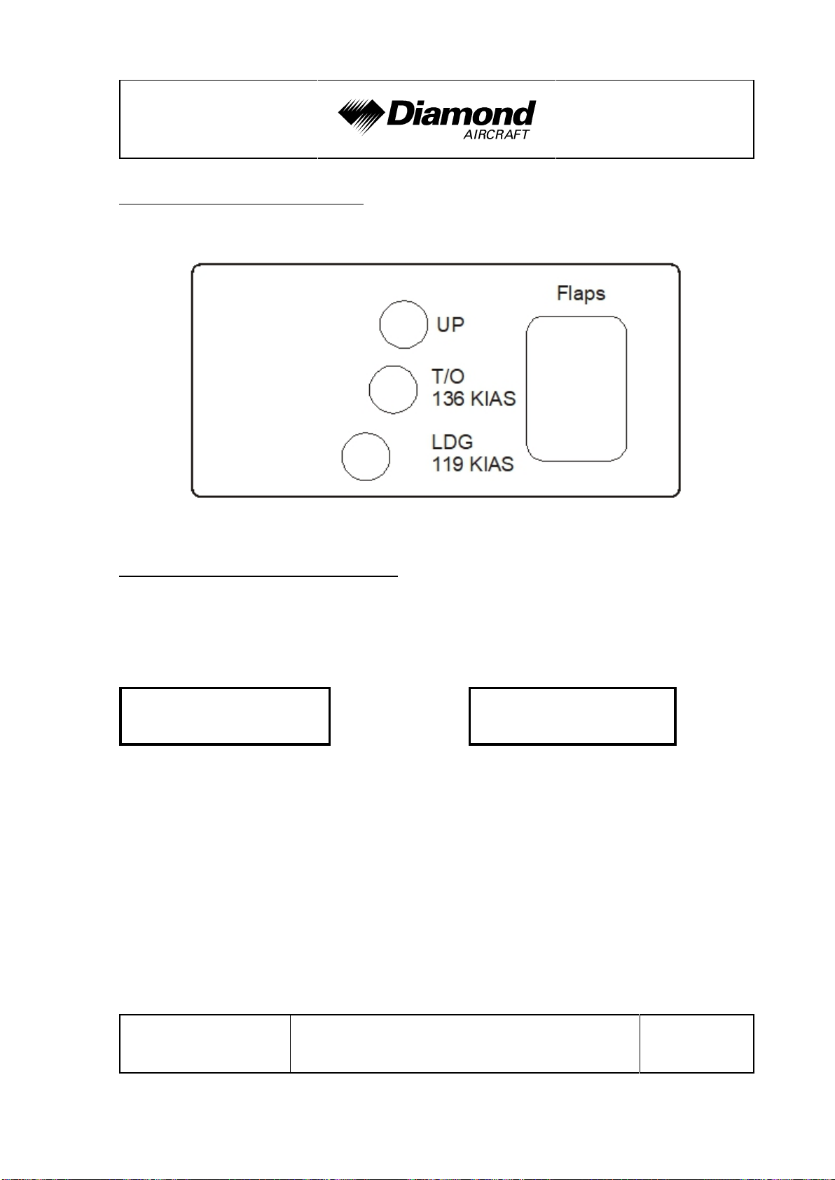
LDG 119 KIAS Do not exceed these
extended speed
T/O 136 KIAS
v
LO
Max. landing
Extension v
LOE
gear operating
speed
v
LE
Max. landing gear extended speed 205 KIAS Do not exceed this
Retraction v
LOR
Page 2 - 4 Rev. 0 11-Jan-2019
speeds with the given
flap setting.
205 KIAS Do not operate the
landing gear above this
162 KIAS
speed.
speed with the landing
gear extended.
DOT
Doc. No. 11.01.05-E
approved
Page 44

DA 62 AFM Operating Limitations
Airspeed KIAS Remarks
v
v
v
MCA
NO
NE
Minimum
control speed
airborne
T/O 70 KIAS With one engine
inoperative, keep
UP 76 KIAS
airspeed above this
limit.
Max. structural cruising speed 162 KIAS Do not exceed this
speed except in smooth
air, and then only with
caution.
Never exceed speed in smooth air 205 KIAS Do not exceed this
speed in any operation.
Doc. No. 11.01.05-E Rev. 0 11-Jan-2019
DOT
Page 2 - 5
approved
Page 45

Operating Limitations DA 62 AFM
2.3 AIRSPEED INDICATOR MARKINGS
Marking KIAS Significance
White arc 64 -119 KIAS Operating range with flaps fully extended.
If MÄM 62-001 is
carried out:
69 - 119 KIAS
70 - 162 KIAS
Green arc
If MÄM 62-001 is
carried out:
73 - 162 KIAS
Yellow arc 162 - 205 KIAS ‘Caution’ range - “Only in smooth air”.
87 KIAS
Blue radial
If MÄM 62-001 is
carried out:
89 KIAS
Red radial 76 KIAS Minimum control speed, single engine.
Red radial 205 KIAS Maximum speed for all operations - vNE.
Normal operating range.
Best rate of climb speed, single engine.
Page 2 - 6 Rev. 0 11-Jan-2019
DOT
Doc. No. 11.01.05-E
approved
Page 46

DA 62 AFM Operating Limitations
2.4 POWER-PLANT LIMITATIONS
a) Number of engines : 2
b) Engine manufacturer : Austro Engine
c) Engine designation : E4P-C
d) RPM limitations (shown as propeller RPM)
Maximum take-off (rpm) : 2300 RPM
Maximum continuous (rpm) : 2200 RPM
Maximum overspeed : 2500 RPM max. 20 sec
e) Engine power
Max. take-off power : 100% (132 kW) max. 5 min
Max. continuous power : 95% (126 kW)
f) Oil pressure (absolute)
Minimum < 1500 RPM : 0.9 bar (13.05 psi)
Minimum $ 1500 RPM : 2.5 bar (36.26 psi)
Maximum : 6.5 bar (94.25 psi)
Normal range : 2.5 bar - 6 bar (36.26 psi - 87.02 psi)
g) Oil quantity
Minimum : 5.0 l (5.28 qts)
Maximum : 7.0 l (7.40 qts)
Maximum oil consumption : 0.1 liter/h (0.11 qts/h)
Doc. No. 11.01.05-E Rev. 0 11-Jan-2019
DOT
Page 2 - 7
approved
Page 47

Operating Limitations DA 62 AFM
h) Oil temperature
Minimum : -30 °C (-22 °F)
Maximum : 139 °C (282 °F)
Normal range : 50 °C - 135 °C (122 °F - 275 °F)
i) Gearbox temperature
Minimum : -30 °C (-22 ° F)
Minimum (full load) : 35 °C (95 °F)
Maximum : 120 °C (248 °F)
NOTE
A cautionary (yellow) gearbox temperature range is not
imposed by the engine manufacturer. However, there is a
delay between power changes and gearbox temperature.
Therefore, a cautionary range has been added to the G1000
gearbox temperature instrument solely to make the pilot
attentive to the gearbox temperature approaching the
maximum allowable limit. There is no specific time limit
associated with operating in the cautionary gearbox
temperature range.
j) Coolant temperature
Minimum (at start-up) : -30 °C (-22 °F)
Minimum (full load) : 60 °C (140 °F)
Maximum : 100 °C (212 °F)
Page 2 - 8 Rev. 0 11-Jan-2019
DOT
Doc. No. 11.01.05-E
approved
Page 48

DA 62 AFM Operating Limitations
k) Fuel temperature
Minimum : -30 °C (-22 °F)
Maximum : 60 °C (140 °F)
l) Fuel pressure (absolute)
Minimum : 4 bar (58.0 psi)
Maximum : 7 bar (101.5 psi)
NOTE
The fuel pressure is not indicated on the G1000; a fuel
pressure warning will illuminate on the PFD if the pressure
is below limit.
m) Voltage
Minimum : 24.1 V
Maximum : 32.0 V
n) Amperage
Maximum : 70 A
o) Propeller manufacturer : mt-Propeller
p) Propeller designation : MTV-6-R-C-F/CF 194-80
q) Propeller diameter : 194 cm (76.38 in)
r) Prop. pitch angle (@ 0.75 R) : 11° ± 0.2° (low pitch)
80° ± 1° (feathered position)
s) Governor : mt-Propeller P-877-16 electrical governor with
feather position
Doc. No. 11.01.05-E Rev. 0 11-Jan-2019
DOT
Page 2 - 9
approved
Page 49

Operating Limitations DA 62 AFM
t) Oil specification:
SAE Grade 5W-30:
SAE Grade 5W-40:
SHELL HELIX ULTRA
ADDINOL SUPER POWER MV 0537
BP VISCO 5000
REPSOL ELITE COMMON RAIL
GULF FORMULA GMX
AEROSHELL Oil Diesel Ultra
CASTROL Edge 5W-30 A3
CASTROL Edge Professional A3
G-Energy F Synth
TOTAL Quartz 9000 Energy
SHELL HELIX ULTRA
LIQUI MOLY LEICHTLAUF HIGH TECH
MEGOL MOTORENOEL HIGH CONDITION
PETRONAS Syntium 3000
LUKOIL LUXE SYNTHETIC
CASTROL Edge Professional A3
CASTROL Magnatec Professional A3
VALVOLINE SynPower HST
VALVOLINE SynPower
GULF Formula GX
AUSTRO ENGINE Aero
produced by Liqui Moly
recommended by Austro Engine GmbH
SAE Grade 0W-40:
CASTROL SLX PROFESSIONAL LONGTEC
CASTROL Edge 0W-40 A3/B4
CASTROL Edge Professional A3
SHELL Helix Ultra
Page 2 - 10 Rev. 0 11-Jan-2019
DOT
Doc. No. 11.01.05-E
approved
Page 50

DA 62 AFM Operating Limitations
CAUTION
Only engine oils conforming to MB 229.5 specification are
approved by Austro Engine GmbH to be used for operation.
Use only one type of approved E4 engine oil for an oil
change.
NOTE
It is not recommended to mix different SAE grades.
u) Gearbox oil (propeller gearbox) : SHELL SPIRAX GSX 75W-80
SHELL SPIRAX S6 GXME 75W-80
v) Coolant : Distilled water/cooler protection (BASF
Glysantin Protect Plus / G48) 1/1. The
freezing point of the coolant is -38°C
(-36.4 °F).
CAUTION
If the coolant or gearbox oil level is low the reason must be
determined and the problem must be corrected by authorized
personnel.
w) Maximum restart altitude : 20,000 ft pressure altitude
for immediate restarts
10,000 ft pressure altitude
for restarts within two minutes
If MÄM 62-168 (engine software
VC33_2P_05_19 or later approved
software) is installed: 15,000 ft pressure altitude
Doc. No. 11.01.05-E Rev. 0 11-Jan-2019
for immediate restart
DOT
Page 2 - 11
approved
Page 51

Operating Limitations DA 62 AFM
Up to 10,000 ft pressure altitude:
OAT
Max. engine
OFF time
[° C] [° F] [minutes]
below -15 below 5 2
-15 to -5 5 to 23 5
above -5 above 23 10
x) Restart airspeed (starter) : max. 80 KIAS or airspeed for a stationary
propeller, whichever is lower.
WARNING
V
is 76 KIAS and should be considered when attempting
MCA
to engine restart with the starter and obtaining a stationary
propeller. This limitation should be observed.
Restart airspeed (windmilling) : Maximum: 115 KIAS
Minimum: 110 KIAS below 10,000 ft
100 KIAS above 10,000 ft
y) No intentional shutdown below 3,000 ft AGL and above 10,000 ft pressure altitude.
DOT
Page 2 - 12 Rev. 0 11-Jan-2019
Doc. No. 11.01.05-E
approved
Page 52

DA 62 AFM Operating Limitations
2.5 ENGINE INSTRUMENT MARKINGS
Engine instrument markings and their color code significance are shown in the tables
below.
Indi-
cation
RPM -- --
Oil
pressure
Oil
temp.
Coolant
temp.
Gearbox
temp.
Load -- -- up to 95% 95 - 100% --
Red
arc/bar
=
lower
prohibited
range
below 0.9 bar 0.9 to 2.5 bar 2.5 to 6.0 bar 6.0 to 6.5 bar
below -30°C -30° to 50°C 50° to 135°C
below -30°C -30° to 60°C 60° to 95°C 95° to 100°C above 100°C
below -30°C -30° to 35°C 35° to 115°C
Yellow
arc/bar
=
caution
range
Green
arc/bar
=
normal
operating
range
up to
2200 RPM
Yellow
arc/bar
=
caution
range
2200 to 2300
RPM
135° to
139°C
115° to
120°C
Red
arc/bar
upper
prohibited
range
above
2300 RPM
above
6.5 bar
above 139°C
above 120°C
=
Fuel
temp.
Ammeter -- -- up to 60A 60 to 70A above 70A
Voltmeter
Fuel qty.
Doc. No. 11.01.05-E Rev. 0 11-Jan-2019
below -30°C -- -30° to 55°C 55° to 60°C above 60°C
below 24.1V 24.1 to 25V 25 to 30V 30 to 32V above 32V
below
--
1 US gal
1 to 25
-- --
US gal
DOT
Page 2 - 13
approved
Page 53

Operating Limitations DA 62 AFM
2.6 WARNING, CAUTION AND ADVISORY ALERTS
2.6.1 WARNING, CAUTION AND ADVISORY ALERTS ON THE G1000
NOTE
The alerts described in the following are displayed on the
Garmin G1000. Section 7.10 includes a detailed description
of the alerts.
The following tables show the color and significance of the warning, caution and advisory
alerts lights on the G1000.
Color and Significance of the Warning Alerts on the G1000
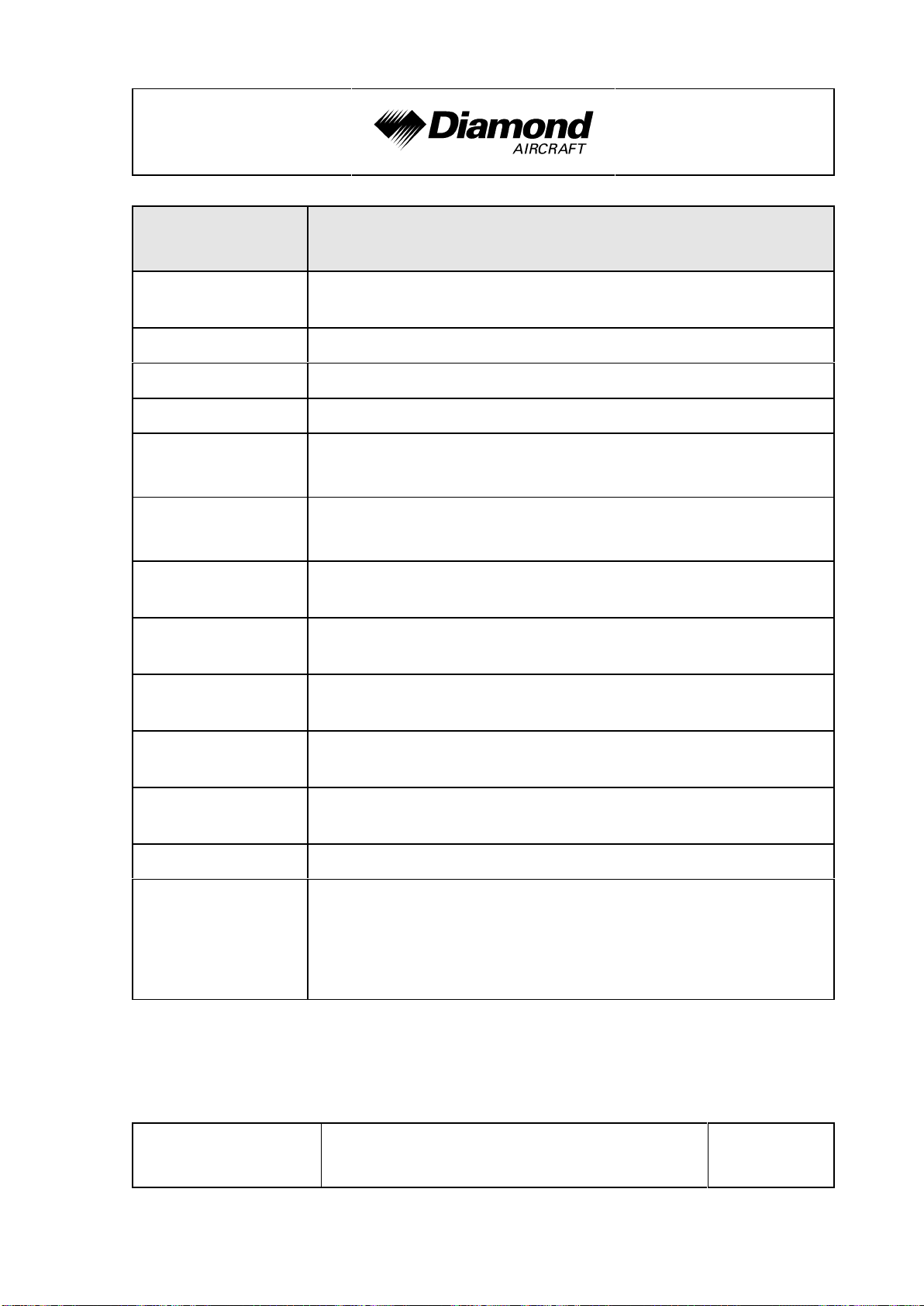
Warning Alerts
(Red)
WARNING One of the warnings listed below is being indicated.
L/R ENG TEMP
L/R OIL TEMP
L/R OIL PRES
L/R FUEL TEMP Left/Right fuel temperature is in the upper red range (too
L/R GBOX TEMP Left/Right engine gearbox temperature is in the upper red
L/R FUEL PRESS Left/Right engine fuel pressure is low.
Left/Right engine coolant temperature is in the upper red
range (too high/> 100 °C [212 °F]).
Left/Right engine oil temperature is in the upper red range
(too high/> 139 °C [282 °F]).
Left/Right engine oil pressure is in the lower red range
(too low/< 0.9 bar [13.05 psi]).
high/> 60 °C [140 °F])
range (too high/> 120 °C [248 °F]).
Meaning/Cause
Page 2 - 14 Rev. 0 11-Jan-2019
DOT
Doc. No. 11.01.05-E
approved
Page 54
DA 62 AFM Operating Limitations
Warning Alerts
(Red)
L/R ALTN AMPS Left/Right engine alternator output is in the upper red range
(too high/> 70 A).
L/R ENG FIRE Left/Right engine fire detected.
L/R STARTER Left/Right engine starter is engaged.
L/R DOOR OPEN Left/Right pilot door is/are not closed and locked.
REAR DOOR
Passenger door is not closed and locked.
OPEN
FWD DOOR
Left/Right baggage door is/are not closed and locked.
OPEN
ATTITUDE FAIL The display system is not receiving attitude reference
information from the AHRS.
AIRSPEED FAIL The display system is not receiving airspeed input from the
air data computer.
Meaning/Cause
ALTITUDE FAIL The display system is not receiving altitude input from the air
data computer.
VERT SPEED
FAIL
HDG The display system is not receiving valid heading input from
WARN RAIM position warning. The nav deviation bar is removed.
Red X or
yellow X
Doc. No. 11.01.05-E Rev. 0 11-Jan-2019
The display system is not receiving vertical speed input from
the air data computer.
the AHRS.
A red or yellow (if MÄM 62-254 is installed) X through any
display field, such as com frequencies, nav frequencies, or
engine data, indicates that the display field is not receiving
valid data.
DOT
Page 2 - 15
approved
Page 55

Operating Limitations DA 62 AFM
Color and Significance of the Caution Alerts on the G1000
Caution Alerts
(Amber)
A fault was detected by the left/right engine ECU A (one
reset of minor faults is possible)
L/R ECU A FAIL
L/R ECU B FAIL
L/R FUEL LOW Left/Right main tank fuel quantity is low.
L/R ALTN FAIL Left/Right engine alternator has failed.
L/R VOLTS LOW Left/Right engine bus voltage is too low (< 25 V).
or
ECU A is being tested during FADEC-test procedure during
the 'Before Take-Off Check'.
A fault was detected by the left/right engine ECU B (one
reset of minor faults is possible)
or
ECU B is being tested during FADEC-test procedure during
the 'Before Take-Off Check'.
Meaning/Cause
L/R COOL LVL Left/Right engine coolant level is low.
PITOT FAIL Pitot heat has failed.
PITOT HT OFF Pitot heat is OFF.
STAL HT FAIL Stall warning heat has failed.
STAL HT OFF Stall warning heat is OFF.
LOI GPS integrity is insufficient for the current phase of flight.
AHRS ALIGN:
Keep Wings Level
L/R AUX FUEL E Left/Right auxiliary fuel tank empty (if installed).
CHECK GEAR Landing gear is not down and locked.
DEICE LVL LO De-icing fluid level is low (if installed).
Page 2 - 16 Rev. 0 11-Jan-2019
The AHRS (Attitude and Heading Reference System) is
aligning.
DOT
Doc. No. 11.01.05-E
approved
Page 56

DA 62 AFM Operating Limitations
Caution Alerts
(Amber)
DEIC PRES HI De-icing pressure is high (if installed).
DEIC PRES LO De-icing pressure is low (if installed).
Color and Significance of the Advisory Alerts on the G1000
Advisory Alerts
(White)
L/R GLOW ON Left/Right engine glow plug active.
L/R AUXPUMP
ON
PFD FAN FAIL Cooling fan for the PFD is inoperative.
MFD FAN FAIL Cooling fan for the MFD is inoperative.
Fuel transfer from auxiliary to main tank is in progress
(if installed).
Meaning/Cause
Meaning/Cause
GIA FAN FAIL Cooling fan for the GIAs is inoperative.
Doc. No. 11.01.05-E Rev. 0 11-Jan-2019
DOT
Page 2 - 17
approved
Page 57

Operating Limitations DA 62 AFM
2.6.2 OTHER WARNING ALERTS
Warning Alerts on the Instrument Panel
Warning Alert
(Red)
GEAR UNSAFE
WARNING LIGHT
Audible Warning Alerts
Audible Warning
Alert
GEAR
RETRACTED
CHIME TONE
(repeating)
Meaning/Cause
Illuminates if the landing gear is neither in the final up nor in
the down & locked position.
Meaning/Cause
Resounds if the landing gear is in retracted configuration and
the flaps move into LDG position or when the power lever is
placed in a position below approximately 25%.
Page 2 - 18 Rev. 0 11-Jan-2019
DOT
Doc. No. 11.01.05-E
approved
Page 58
DA 62 AFM Operating Limitations
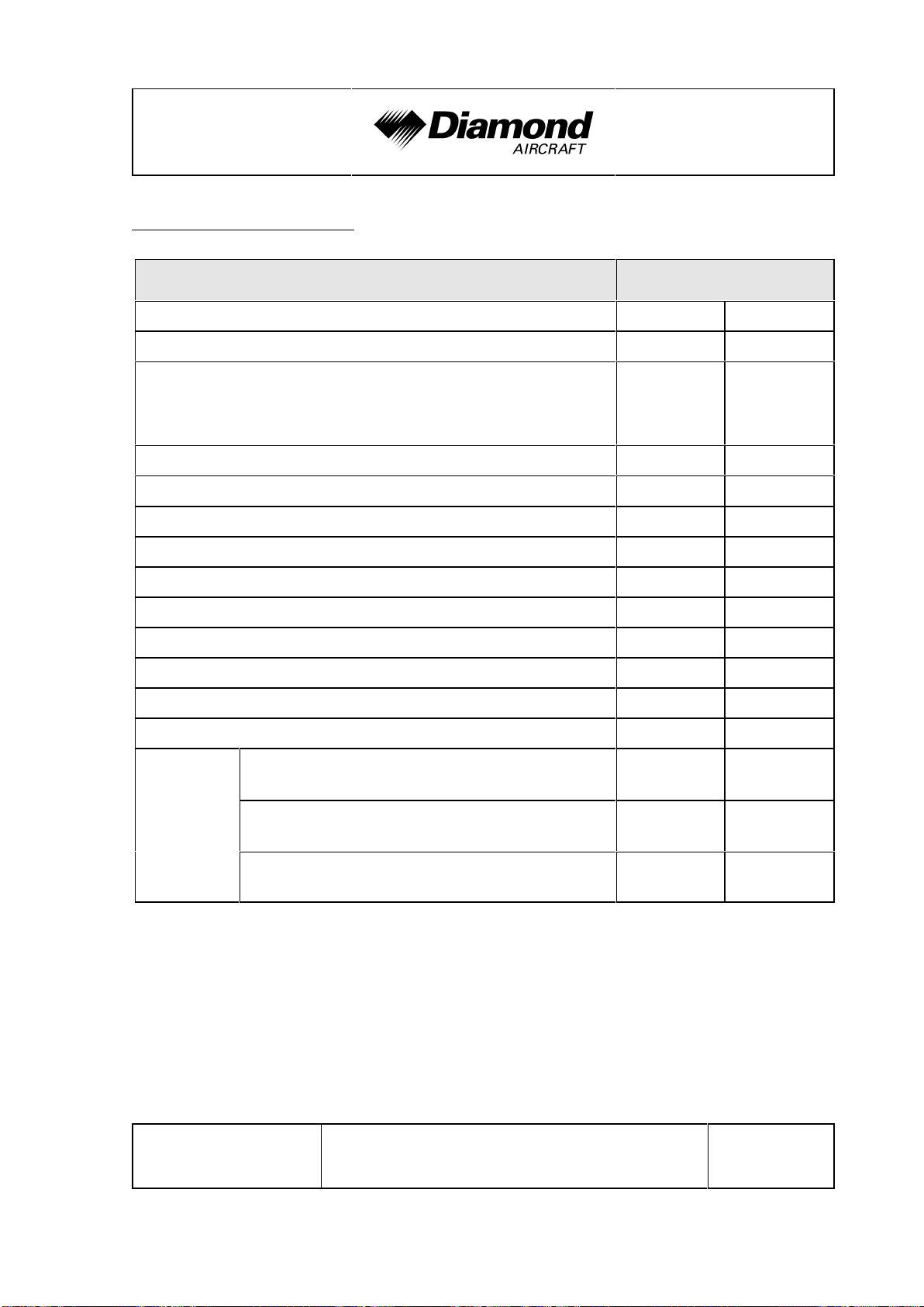
2.7 MASS (WEIGHT)
Value
Minimum flight mass 1600 kg 3329 lb
Maximum take-off mass (if MÄM 62-001 is carried out) 2300 kg 5071 lb
Maximum take-off mass
(if MÄM 62-001 is NOT carried out
or if OÄM 62-018 AND MÄM 62-001 are carried out)
Maximum zero fuel mass 2036 kg 4489 lb
Maximum landing mass 2300 kg 5071 lb
Maximum zero fuel mass (if MÄM 62-063 is carried out) 2200 kg 4850 lb
Max. load in LH nose baggage compartment 30 kg 66 lb
Max. load in RH nose baggage compartment 30 kg 66 lb
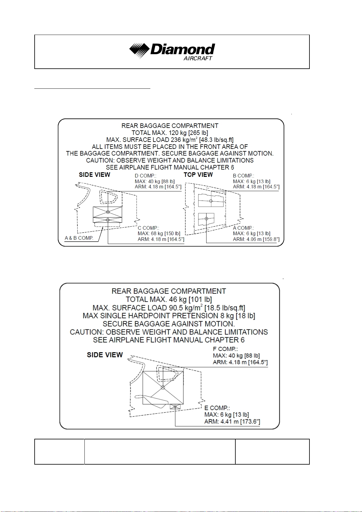
Max. total load in rear baggage compartment 120 kg 265 lb
Max. load in section A of rear baggage compartment 6 kg 13 lb
Max. load in section B of rear baggage compartment 6 kg 13 lb
Max. load in section C of rear baggage compartment 68 kg 150 lb
Mass (Weight)
1999 kg 4407 lb
Max. load in section D of rear baggage compartment 40 kg 88 lb
If OÄM
62-019
is carried
out
Max. load total load in rear baggage
compartment
Max. load in section E of rear baggage
compartment
Max. load in section F of rear baggage
compartment
46 kg 101 lb
6 kg 13 lb
40 kg 88 lb
WARNING
Exceeding the mass limits will lead to overstressing of the
airplane as well as to degradation of flight characteristics and
flight performance.
Doc. No. 11.01.05-E Rev. 0 11-Jan-2019
DOT
Page 2 - 19
approved
Page 59

Operating Limitations DA 62 AFM
2.8 CENTER OF GRAVITY
Datum Plane
The datum plane (DP) is a plane which is normal to the airplane’s longitudinal axis and
in front of the airplane as seen from the direction of flight. The airplane’s longitudinal axis
is parallel with the floor of the nose baggage compartment. When the floor of the nose
baggage compartment is aligned horizontally, the datum plane is vertical. The datum plane
is located 2.196 meters (86.46 in) forward of the most forward point of the root rib on the
stub wing (refer to figure in Section 6.2).
Center of Gravity Limitations
The center of gravity (CG position) for flight conditions must be between the following
limits:
Most forward flight CG:
2.340 m (92.13 in) aft of datum plane at 1600 kg (3527 lb) to 1800 kg (3968 lb)
2.460 m (96.85 in) aft of datum plane at max. take-off mass (see Section 2.7)
linear variation in between
Most rearward flight CG:
2.460 m (96.85 in) aft of datum plane at 1600 kg (3527 lb)
2.510 m (98.82 in) aft of datum plane at 1900 kg (4189 lb) to 1999 kg (4407 lb)
2.530 m (99.61 in) aft of datum plane at MTOM
linear variation in between
Refer to Section 6.4.4 for a graphical illustration of the CG limitations.
WARNING
Exceeding the center of gravity limitations reduces the
controllability and stability of the airplane.
Page 2 - 20 Rev. 0 11-Jan-2019
DOT
Doc. No. 11.01.05-E
approved
Page 60

DA 62 AFM Operating Limitations
2.9 APPROVED MANEUVERS
The airplane is certified in the Normal Category in accordance with AWM 523.
Approved Maneuvers
1) All normal flight maneuvers;
2) Stalling (with the exception of dynamic stalling); and
3) Lazy Eights, Chandelles, as well as steep turns and similar maneuvers, in which
an angle of bank of not more than 60° is attained.
CAUTION
Aerobatics, spinning and flight maneuvers with more than 60°
of bank are not permitted in the Normal Category. Stalling
with asymmetric power or one engine inoperative is not
permitted.
CAUTION
Intentional negative-g maneuvers are not permitted.
Doc. No. 11.01.05-E Rev. 0 11-Jan-2019
DOT
Page 2 - 21
approved
Page 61

Operating Limitations DA 62 AFM
2.10 MANEUVERING LOAD FACTORS
NOTE
The tables below show structural limitations. The load factor
limits for the engine must also be observed. Refer to the
corresponding operation manual for the engine.
at v
O
at v
NE
with flaps in APP
or LDG position
Positive 3.8 3.8 2.0
Negative -1.52 0.0 0.0
WARNING
Exceeding the maximum structural load factors will lead to
overstressing of the airplane.
CAUTION
Intentional negative-g maneuvers are not permitted.
Page 2 - 22 Rev. 0 11-Jan-2019
DOT
Doc. No. 11.01.05-E
approved
Page 62

DA 62 AFM Operating Limitations
2.11 OPERATING ALTITUDE
The maximum operating altitude is 20,000 ft (6,096 m) pressure altitude.
2.12 FLIGHT CREW
Minimum crew : 1 (one person)
Maximum number of occupants : 5 (five persons)
7 (seven persons, if OÄM 62-019 is installed)
2.13 KINDS OF OPERATION
Provided that national operational requirements are met, the following kinds of operation
are approved:
• daytime flights according to Visual Flight Rules (VFR)
• with the appropriate equipment: night flights according to Visual Flight Rules (NVFR)
• with the appropriate equipment: flights according to Instrument Flight Rules (IFR)
• take-off and landing on paved surfaces
• take-off and landing on grass surfaces
Flights into known or forecast thunderstorms are prohibited.
Flights into known or forecast icing conditions are prohibited.
Minimum Operational Equipment (Serviceable)
The following table lists the minimum serviceable equipment required for operation.
Additional minimum equipment for the intended operation may be required by national
operating rules and also depends on the route to be flown.
Doc. No. 11.01.05-E Rev. 0 11-Jan-2019
DOT
Page 2 - 23
approved
Page 63

Operating Limitations DA 62 AFM
NOTE
Many of the items of minimum equipment listed in the
following table are integrated in the G1000.
Flight &
navigation
instruments
For Daytime
VFR Flights
* airspeed indicator
(on G1000 PFD or
backup)
* altimeter (on G1000
PFD or backup)
* magnetic compass
* 1 headset, used by
pilot in command
In Addition for
Night VFR Flights
* vertical speed
indicator (VSI)
* attitude gyro
(artificial horizon; on
G1000 PFD or
backup)
* turn & bank
indicator (on G1000
PFD)
* directional gyro
* VHF radio (COM)
* VOR receiver
* transponder
(XPDR), mode A
and mode C
* GPS receiver (part
of G1000)
In Addition for
IFR Flights
* second airspeed
indicator (both, on
G1000 PFD and
backup)
* second altimeter
(both, on G1000
PFD and backup)
* second attitude
gyro (both, on
G1000 PFD and
backup)
* second VHF radio
(COM)
* VOR-LOC-GP
receiver
* second GPS
receiver (part of
G1000)
* second headset
Page 2 - 24 Rev. 0 11-Jan-2019
DOT
Doc. No. 11.01.05-E
approved
Page 64

DA 62 AFM Operating Limitations
Engine
Instruments
For Daytime VFR
Flights
* fuel qty. (2x)
* oil press. (2x)
* oil temp. (2x)
* coolant temp. (2x)
* coolant level
indicator (2x)
* gearbox temp. (2x)
* load (2x)
* prop. RPM (2x)
* fuel temp. left &
right tank
* fuel flow (2x)
* fuel px warning
In Addition for
Night VFR Flights
* ammeter
* voltmeter
In Addition for
IFR Flights
Lighting * position lights
* strobe lights (anti
collision lights)
* landing light
* instrument lighting
* flood light
* flashlight
Doc. No. 11.01.05-E Rev. 0 11-Jan-2019
DOT
Page 2 - 25
approved
Page 65

Operating Limitations DA 62 AFM
Other
operational
minimum
equipment
For Daytime VFR
Flights
* stall warning
system
* alternate means for
fuel quantity
indication (see
Section 7.9)
* safety belts for
each occupied seat
* Airplane Flight
Manual
* Egress Hammer
In Addition for
Night VFR Flights
* Pitot heating
system
* alternate static
valve
In Addition for
IFR Flights
* sufficient charge
for the internal
battery of the
Standby Attitude
Module
NOTE
A list of approved equipment can be found in Chapter 6.
Engine Systems and Equipment
All engine systems and equipment must be functional prior to airplane take-off. Any engine
system or equipment failure must be corrected before next flight.
DOT
Page 2 - 26 Rev. 0 11-Jan-2019
approved
Doc. No. 11.01.05-E
Page 66

DA 62 AFM Operating Limitations
2.14 FUEL
Approved fuel grades: JET A, JET A-1 (ASTM D 1655)
TS-1 (Russia, GOST 10227-86)
TS-1 (Ukraine, GSTU 320.00149943.011-99)
RT (Russia, GOST 10227-86)
RT (Ukraine GSTU 320.00149943.007-97)
No. 3 Jet Fuel (China, GB 6537-2006)
JP-8 (F34) (USA, MIL-DTL-83133G-2010)
and blends of the above listed fuel grades.
NOTE
A minimum cetane number of 36 determined acc. to
EN ISO 5165/ASTM D613 is recommended.
NOTE
Use only uncontaminated fuel from reliable sources.
Any mixture of the different types of fuel additives is not permitted.
OPERATION WITH ANTI-MICROBIAL LIFE FUEL ADDITIVES
The application of the following additives is permitted:
- KATHON FP 1.5 : max. 100 ppm
- BIOBOR JF : max. 270 ppm for initial treatment
max. 135 ppm for permanent use after initial treatment
Doc. No. 11.01.05-E Rev. 0 11-Jan-2019
DOT
Page 2 - 27
approved
Page 67

Operating Limitations DA 62 AFM
CAUTION
In case of an unknown or an over dosage of the fuel additives
the fuel system must be purged until the dosage is within the
permitted limits.
NOTE
The specified additives are qualified for the operation with
the certified fuel grades.
NOTE
The instructions of the fuel additive supplier must be followed.
OPERATION WITH ANTI-ICING FUEL ADDITIVES
The application of the following additive is permitted:
- PRIST Hi-Flash : max. 1500 ppm
CAUTION
The use of PRIST Hi-Flash fuel additive is only permitted with
JET A, JET A-1 (ASTM D 1655) and JP-8 (F34).
NOTE
The instructions of the fuel additive supplier must be followed.
Page 2 - 28 Rev. 0 11-Jan-2019
DOT
Doc. No. 11.01.05-E
approved
Page 68

DA 62 AFM Operating Limitations
Main Tanks
US gal Liter US gal Liter US gal Liter
Total fuel quantity 2 x 26.0 2 x 98.4 2 x 18.5 2 x 70.0 2 x 44.5 2 x 168.4
Usable fuel 2 x 25.0 2 x 94.6 2 x 18.2 2 x 68.9 2 x 43.2 2 x 163.5
Max. permissible
difference LH/RH
5.0 18.9
Auxiliary Tanks
Total
(if installed)
Doc. No. 11.01.05-E Rev. 0 11-Jan-2019
DOT
Page 2 - 29
approved
Page 69
Operating Limitations DA 62 AFM
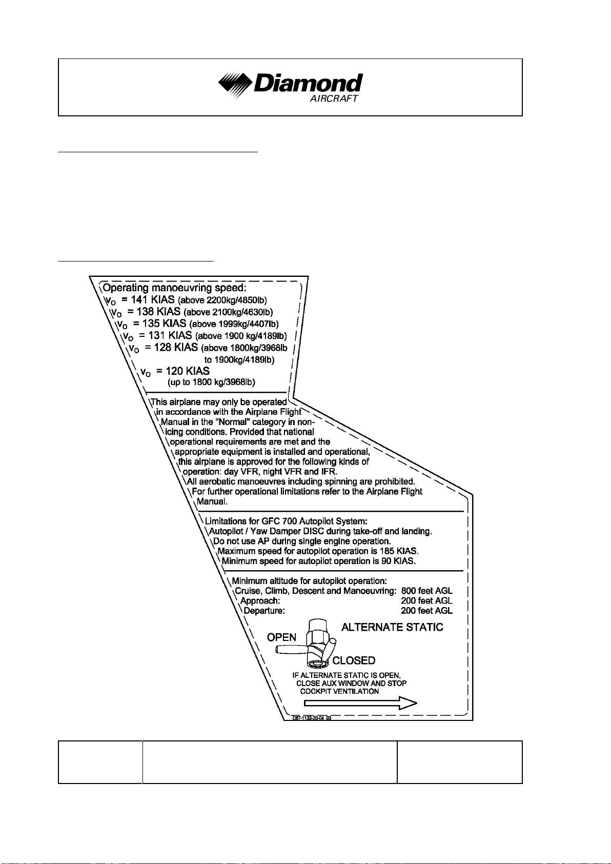
2.15 LIMITATION PLACARDS
All limitation placards are shown below. A list of all placards is included in the Airplane
Maintenance Manual (Doc. No. 7.02.25), Chapter 11.
The following limitation placards are in the forward view of the pilot:
Left of the Instrument Panel:
Page 2 - 30 Rev. 0 11-Jan-2019
DOT
Doc. No. 11.01.05-E
approved
Page 70

DA 62 AFM Operating Limitations
On the Instrument Panel:
LANDING GEAR
vLE / v
v
On the Emergency Landing Gear Extension Lever:
= 205 KIAS
LOE
= 162 KIAS
LOR
EMERGENCY
Gear Extension
Max. 162 KIAS
On the Instrument Panel:
Standard Tank: Auxiliary Tank (if installed):
max. usable
fuel: 2 x 25 US gal
max. difference LH/RH
tank: 5 US gal
max. usable
fuel main tank:
2 x 25 US gal
auxiliary tank:
2 x 18.2 US gal
max. difference LH/RH
main tank: 5 US gal
Doc. No. 11.01.05-E Rev. 0 11-Jan-2019
DOT
approved
Page 2 - 31
Page 71

Operating Limitations DA 62 AFM
(a) Next to Each of the Two Fuel Filler Necks;
(b) In Addition Next to Each of the Two Auxiliary Fuel Filler Necks (if installed):
WARNING
APPROVED FUEL
JET-A1,
or see Airplane Flight Manual
In Each Cowling, on the Door for the Oil Filler Neck:
OIL
AUSTRO ENGINE
Aero
5W-40
or see Airplane
Flight Manual
OR
OIL
SHELL HELIX
ULTRA
5W-30
or see Airplane
Flight Manual
Page 2 - 32 Rev. 0 11-Jan-2019
DOT
Doc. No. 11.01.05-E
approved
Page 72
DA 62 AFM Operating Limitations
Next to the Flap Selector Switch:
In the Nose Baggage Compartments:
LH Nose Baggage Compartment: RH Nose Baggage Compartment:
Max. Baggage:
30 kg (66 lb)
Max. Baggage:
30 kg (66 lb)
Doc. No. 11.01.05-E Rev. 0 11-Jan-2019
DOT
Page 2 - 33
approved
Page 73
Operating Limitations DA 62 AFM
In the Rear Baggage Compartment:
If OÄM 62-019 is NOT carried out:
If OÄM 62-019 is carried out:
Page 2 - 34 Rev. 0 11-Jan-2019
DOT
Doc. No. 11.01.05-E
approved
Page 74

DA 62 AFM Operating Limitations
Beside the Door Locking Device Installed in the Passengers' Door:
EMERGENCY EXIT:
The keylock must be
unlocked during flight!
On the Bottom Center of the Instrument Panel:
NO SMOKING
On the Armrest with Integrated Keypad (if OÄM 62-031 is carried out):
STOW FOR TAKE-OFF AND
LANDING, IN ALL EMERGENCIES
AND ABNORMAL OPERATING
PROCEDURES
Doc. No. 11.01.05-E Rev. 0 11-Jan-2019
DOT
Page 2 - 35
approved
Page 75

Operating Limitations DA 62 AFM
2.16 OTHER LIMITATIONS
2.16.1 FUEL TEMPERATURE
From -30 °C to 60 °C (from -22 °F to 140 °F).
2.16.2 BATTERY CHARGE
Take-off for a Night VFR or IFR flight with a discharged battery is not permitted.
NOTE
The most common indication of a discharged battery is
that the engine cannot be started with battery power.
The use of an external power supply for engine starting with a discharged airplane battery
is not permitted if the subsequent flight is intended to be a Night VFR or IFR flight. In this
case, the airplane main battery must be charged first.
2.16.3 DOOR LOCKING DEVICE
The LH & RH CREW DOORS and the passenger door must not be blocked by the key
lock during operation of the airplane.
Page 2 - 36 Rev. 0 11-Jan-2019
DOT
Doc. No. 11.01.05-E
approved
Page 76

DA 62 AFM Operating Limitations
2.16.4 ELECTRONIC EQUIPMENT
The use and switching on of electronic equipment other than that which is part of the
equipment of the airplane is not permitted, as it could lead to interference with the
airplane's avionics.
Examples of undesirable items of equipment are:
- Mobile phones
- Remote radio controls
- Video screens employing CRTs
- Minidisc recorders in record mode
This list is not exhaustive.
The use of laptop and handheld computers, including those with CD-ROM drives, CD
and mini-disc players in the replay mode, cassette players and video cameras is permitted.
All this equipment however should be switched off for take-off and landing.
NOTE
Refer to the applicable flight authority for the use of electronic
equipment associated with electronic flight bag operation.
Doc. No. 11.01.05-E Rev. 0 11-Jan-2019
DOT
Page 2 - 37
approved
Page 77
Operating Limitations DA 62 AFM
2.16.5 GARMIN G1000 AVIONICS SYSTEM
1. The Garmin G1000 Cockpit Reference Guide, P/N 190-01896-( ) or Garmin
G1000 NXi Cockpit Reference Guide, P/N 190-01905-( ), appropriate revision must
be immediately available to the flight crew.
2. The G1000 must utilize the software Garmin 010-01895-00, the Garmin G1000 NXi
must utilize the software Garmin 010-01895-04, approved software in accordance
with the mandatory service bulletin DAI MSB 62-003, latest version.
Software Part Number Approved
Version
System
010-01895-( )
Manifest
006-B0093-( ) GPS1, GPS2
006-B0172-( ) GTX1-GIA1, GTX1-GIA2
006-B0190-( ) GIA1, GIA2
006-B0193-( ) GEA1-GIA1; GEA1-GIA2
006-B0203-( ) GMA1-GIA1, GMA1-GAI2
006-B0223-( ) GRS1-GIA1, GRS1-GIA2
006-B0224-( ) GMU1
006-B0319-( ) PFD1, MFD1
006-B0328-( )
006-B0329-( )
006-C0048-( ) GMU1 FPGA
006-C0049-( ) GRS1 FPGA
for approved
version see
DAI MSB
62-003
latest version
Function
006-C0055-( ) GDC1 FPGA
006-D0159-( ) GRS1 MV DB
006-D0202-( )
006-B0261-( ) GDC1-GIA1
006-B0081-( ) COM1, COM2
DOT
Page 2 - 38 Rev. 0 11-Jan-2019
approved
Doc. No. 11.01.05-E
Page 78

DA 62 AFM Operating Limitations
Software Part Number Approved
Version
006-B0083-() GS1, GS2
006-B0082-() NAV1, NAV2
Function
NOTE
The database version is displayed on the MFD power-up
page immediately after system power-up and must be
acknowledged. The remaining system software versions can
be verified on the AUX group sub-page 5, "AUX-SYSTEM
STATUS".
3. IFR enroute, oceanic and terminal navigation predicated upon the G1000 GPS receiver
is prohibited unless the pilot verifies the currency of the database or verifies each
selected way point for accuracy by reference to current approved data.
4. Instrument approach navigation predicated upon the G1000 GPS receiver must be
accomplished in accordance with approved instrument approach procedures that are
retrieved from the GPS equipment database. The GPS equipment database must
incorporate the current update cycle.
NOTE
Not all published approaches are in the FMS database. The
pilot must ensure that the planned approach is in the
database.
(a) Instrument approaches utilizing the GPS receiver must be conducted in the
approach mode, and Receiver Autonomous Integrity Monitoring (RAIM) must
be available at the Final Approach Fix.
(b) Accomplishment of ILS, LOC, LOC-BC, LDA, SDF, MLS or any other type of
Doc. No. 11.01.05-E Rev. 0 11-Jan-2019
DOT
Page 2 - 39
approved
Page 79

Operating Limitations DA 62 AFM
approach not approved for GPS overlay with the G1000 GPS receiver is not
authorized.
(c) Use of the G1000 VOR/ILS receiver to fly approaches not approved for GPS
require VOR/ILS navigation data to be present on the display.
(d) When an alternate airport is required by the applicable operating rules, it must
be served by an approach based on other than GPS or Loran-C navigation,
the airplane must have the operational equipment capable of using that
navigation aid, and the required navigation aid must be operational.
(e) VNAV information may be utilized for advisory information only. Use of VNAV
information for Instrument Approach Procedures does not guarantee step-down
fix altitude protection, or arrival at approach minimums in normal position to
land.
(f) RNAV (GPS) approaches must be conducted utilizing the GPS sensor.
(g) RNP RNAV operations are not authorized, except as noted in Chapter 1 of this
AFM.
5. If not previously defined, the following default settings must be made in the "SYSTEM
SETUP" menu of the G1000 prior to operation (refer to Pilot's Guide for procedure
if necessary):
(a) DIS, SPD : nm, kt (sets navigation units to "nautical miles" and "knots")
(b) ALT, VS : ft, fpm (sets altitude units to "feet" and "feet per minute")
(c) POSITION : deg-min (sets navigation grid units to decimal minutes)
NOTE
Navigation Information is referenced to WGS-84 reference
system, and should only be used where the Aeronautical
Information Publication (including electronic data and
aeronautical charts) conforms to WGS-84 or equivalent.
Page 2 - 40 Rev. 0 11-Jan-2019
DOT
Doc. No. 11.01.05-E
approved
Page 80

DA 62 AFM Operating Limitations
6. When AHRS is required to meet the items listed in the minimum operational equipment
(serviceable) table in Section 2.13 of this AFM, operation is prohibited in the following
areas:
(a) North of 72° N latitude at all longitudes.
(b) South of 70° S latitude at all longitudes.
(c) North of 65° N latitude between longitude 75° W and 120° W (Northern Canada).
(d) North of 70° N latitude between longitude 70° W and 128° W (Northern Canada).
(e) North of 70° N latitude between longitude 85° E and 114° E (Northern Russia).
(f) South of 55° S latitude between longitude 120° E and 165° E (Region south
of Australia and New Zealand).
When day VFR operations are conducted in the above areas, the MFD must be in
a non-heading up orientation.
7. The fuel quantity, fuel required, and fuel remaining functions of the FMS are
supplemental information only and must be verified by the flight crew.
8. The GPS is approved for SBAS operations. Refer to Supplement A33 for SBAS and
P-RNAV Operation.
9. The availability of SafeTaxi®, ChartView, or FliteCharts® in electronic form on the G1000
is for information purposes only, it is still mandatory to carry another source of charts
on-board the airplane.
Doc. No. 11.01.05-E Rev. 0 11-Jan-2019
DOT
Page 2 - 41
approved
Page 81

Operating Limitations DA 62 AFM
2.16.6 AUTOPILOT LIMITATIONS
1. It is the responsibility of the pilot in command to monitor the autopilot when it is
engaged. The pilot should be prepared to immediately disconnect the autopilot and
to take prompt corrective action in the event of unexpected or unusual autopilot
behavior.
2. The autopilot and yaw damper must be disconnected (using the DISC button) during
take-off, landing and single engine operation.
3. Following an autopilot or electric trim malfunction, re-engaging the autopilot or manual
electric trim, or resetting the AFCS/ESP/USP circuit breaker is prohibited until the
cause of the malfunction has been determined and corrected.
4. The Garmin G1000 Cockpit Reference Guide for the Diamond DA 62,
P/N 010-01896-( ) or Garmin G1000 NXi Cockpit Reference Guide for the Diamond
DA62, P/N 010-01905-( ) approved revision must be immediately available to the flight
crew.
5. ILS approaches using the GFC700 / flight director are limited to Category I approaches
only.
6. Autopilot maximum airspeed: 185 KIAS
Autopilot minimum airspeed: 90 KIAS
7. Altitude select captures below 1200 feet AGL are prohibited.
8. The autopilot must be disengaged:
- below 200 ft AGL during approach,
- below 200 ft AGL during departure,
- below 800 ft AGL for all other phases of flight,
- during single engine operation.
9. Overriding the autopilot to change pitch or roll attitude is prohibited. (Disengage or
press CWS while maneuvering.)
Page 2 - 42 Rev. 0 11-Jan-2019
DOT
Doc. No. 11.01.05-E
approved
Page 82

DA 62 AFM Operating Limitations
10. The GFC 700 AFCS pre-flight test must be successfully completed prior to use
of the autopilot, flight director, yaw damper or manual electric trim.
11. A pilot with the seat belt fastened must occupy the left pilot's seat during all
operations.
12. The yaw damper is an integral part of the autopilot system and must not be used
separately.
2.16.7 SMOKING
Smoking in the airplane is not permitted.
2.16.8 GROUND OPERATION
Take-off and landing has been demonstrated on hard paved surfaces (asphalt, concrete,
etc.) and grass runways.
2.16.9 GARMIN GWX 70 WEATHER RADAR OPERATION
WARNING
The Garmin GWX 70 Weather Radar System (if installed)
must not be operated on ground except in standby mode
during taxiing. If the system is transmitting, it may result in
bodily injury if persons are within the minimum safe distance
of 2.3 m (7.4 ft). Never operate the radar in a hangar or other
enclosure as radiation can be reflected throughout the area.
Doc. No. 11.01.05-E Rev. 0 11-Jan-2019
DOT
Page 2 - 43
approved
Page 83

Operating Limitations DA 62 AFM
2.16.10 USE OF THE SUN VISORS
The sun visors (if installed) may only be used during cruise. During all other phases of
flight, the sun visors must be locked in the fully upward position.
2.16.11 PDF/MFD CONTROL UNIT (KEYPAD)
The PFD/MFD control unit must be stowed during take-off and landing all emergencies
and abnormal operating procedures.
Page 2 - 44 Rev. 0 11-Jan-2019
DOT
Doc. No. 11.01.05-E
approved
Page 84

DA 62 AFM
3.1 INTRODUCTION . . . . . . . . . . . . . . . . . . . . . . . . . . . . . . . . . . . . . . . . 3-4
3.2 AIRPLANE-RELATED G1000 WARNINGS. . . . . . . . . . . . . . . . . . . . 3-6
Emergency
Procedures
CHAPTER 3
EMERGENCY PROCEDURES
Page
3.1.1 GENERAL . . . . . . . . . . . . . . . . . . . . . . . . . . . . . . . . . . . . . . . . 3-4
3.1.2 CERTAIN AIRSPEEDS IN EMERGENCIES . . . . . . . . . . . . . . 3-5
3.1.3 SELECTING EMERGENCY FREQUENCY . . . . . . . . . . . . . . . 3-5
3.2.1 WARNINGS/GENERAL. . . . . . . . . . . . . . . . . . . . . . . . . . . . . . 3-6
3.2.2 L/R ENG TEMP . . . . . . . . . . . . . . . . . . . . . . . . . . . . . . . . . . . . 3-6
3.2.3 L/R OIL TEMP . . . . . . . . . . . . . . . . . . . . . . . . . . . . . . . . . . . . . 3-8
3.2.4 L/R OIL PRES . . . . . . . . . . . . . . . . . . . . . . . . . . . . . . . . . . . . 3-10
3.2.5 L/R GBOX TEMP. . . . . . . . . . . . . . . . . . . . . . . . . . . . . . . . . . 3-11
3.2.6 L/R FUEL TEMP . . . . . . . . . . . . . . . . . . . . . . . . . . . . . . . . . . 3-12
3.2.7 L/R FUEL PRESS . . . . . . . . . . . . . . . . . . . . . . . . . . . . . . . . . 3-13
3.2.8 L/R ALTN AMPS . . . . . . . . . . . . . . . . . . . . . . . . . . . . . . . . . . 3-13
3.2.9 L/R ENG FIRE . . . . . . . . . . . . . . . . . . . . . . . . . . . . . . . . . . . . 3-14
3.2.10 L/R STARTER . . . . . . . . . . . . . . . . . . . . . . . . . . . . . . . . . . . 3-14
3.2.11 DOOR OPEN . . . . . . . . . . . . . . . . . . . . . . . . . . . . . . . . . . . . 3-15
3.3 AIRPLANE-RELATED G1000 CAUTIONS . . . . . . . . . . . . . . . . . . . 3-16
3.3.1 L/R ALTN FAIL . . . . . . . . . . . . . . . . . . . . . . . . . . . . . . . . . . . 3-16
3.4 G1000 SYSTEM WARNINGS . . . . . . . . . . . . . . . . . . . . . . . . . . . . . 3-17
3.4.1 RED X/YELLOW X . . . . . . . . . . . . . . . . . . . . . . . . . . . . . . . . 3-17
3.4.2 ATTITUDE FAIL. . . . . . . . . . . . . . . . . . . . . . . . . . . . . . . . . . . 3-17
3.4.3 AIRSPEED FAIL . . . . . . . . . . . . . . . . . . . . . . . . . . . . . . . . . . 3-17
3.4.4 ALTITUDE FAIL. . . . . . . . . . . . . . . . . . . . . . . . . . . . . . . . . . . 3-17
3.4.5 VERT SPEED FAIL . . . . . . . . . . . . . . . . . . . . . . . . . . . . . . . . 3-18
3.4.6 HDG. . . . . . . . . . . . . . . . . . . . . . . . . . . . . . . . . . . . . . . . . . . . 3-18
Doc. No. 11.01.05-E Rev. 0 11-Jan-2019 Page 3 - 1
Page 85

Emergency
Procedures
3.5 G1000 FAILURES . . . . . . . . . . . . . . . . . . . . . . . . . . . . . . . . . . . . . 3-19
3.5.1 NAVIGATION INFORMATION FAILURE . . . . . . . . . . . . . . . 3-19
3.5.2 PFD OR MFD DISPLAY FAILURE. . . . . . . . . . . . . . . . . . . . 3-19
3.5.3 AHRS FAILURE . . . . . . . . . . . . . . . . . . . . . . . . . . . . . . . . . . 3-20
3.5.4 AIR DATA COMPUTER (ADC) FAILURE . . . . . . . . . . . . . . 3-21
3.5.5 ERRONEOUS OR LOSS OF ENGINE AND
FUEL DISPLAYS . . . . . . . . . . . . . . . . . . . . . . . . . . . . . . . . . 3-21
3.5.6 ERRONEOUS OR LOSS OF WARNING/CAUTION
ANNUNCIATORS . . . . . . . . . . . . . . . . . . . . . . . . . . . . . . . . 3-22
3.6 ABNORMAL ENGINE BEHAVIOUR . . . . . . . . . . . . . . . . . . . . . . . 3-23
3.7 ONE ENGINE INOPERATIVE PROCEDURES . . . . . . . . . . . . . . . 3-24
3.7.1 DETECTING THE INOPERATIVE ENGINE . . . . . . . . . . . . 3-25
3.7.2 ENGINE TROUBLESHOOTING . . . . . . . . . . . . . . . . . . . . . 3-26
DA 62 AFM
3.7.3 ENGINE SECURING (FEATHERING) PROCEDURE . . . . . 3-29
3.7.4 UNFEATHERING & RESTARTING THE
ENGINE IN FLIGHT . . . . . . . . . . . . . . . . . . . . . . . . . . . . . . . 3-30
3.7.5 ENGINE FAILURE DURING TAKE-OFF . . . . . . . . . . . . . . . 3-34
3.7.6 ENGINE FAILURES IN FLIGHT. . . . . . . . . . . . . . . . . . . . . . 3-37
3.7.7 LANDING WITH ONE ENGINE INOPERATIVE . . . . . . . . . 3-39
3.7.8 GO-AROUND/BALKED LANDING WITH ONE
ENGINE INOPERATIVE . . . . . . . . . . . . . . . . . . . . . . . . . . . 3-42
3.7.9 FLIGHT WITH ONE ENGINE INOPERATIVE . . . . . . . . . . . 3-45
3.8 ENGINES OUT LANDING . . . . . . . . . . . . . . . . . . . . . . . . . . . . . . . 3-47
3.9 DITCHING . . . . . . . . . . . . . . . . . . . . . . . . . . . . . . . . . . . . . . . . . . . 3-49
3.10 LANDING GEAR SYSTEM FAILURES . . . . . . . . . . . . . . . . . . . . . 3-50
3.10.1 LANDING GEAR UNSAFE WARNING . . . . . . . . . . . . . . . 3-50
3.10.2 MANUAL EXTENSION OF THE LANDING GEAR . . . . . . 3-52
3.10.3 LANDING WITH GEAR UP . . . . . . . . . . . . . . . . . . . . . . . . 3-54
3.10.4 LANDING WITH A DEFECTIVE TIRE ON THE
MAIN LANDING GEAR . . . . . . . . . . . . . . . . . . . . . . . . . . . 3-55
3.10.5 LANDING WITH DEFECTIVE BRAKES . . . . . . . . . . . . . . 3-56
Page 3 - 2 Rev. 0 11-Jan-2019 Doc. No. 11.01.05-E
Page 86

DA 62 AFM
3.11 FAILURES IN THE ELECTRICAL SYSTEM . . . . . . . . . . . . . . . . . . 3-57
3.12 SMOKE AND FIRE . . . . . . . . . . . . . . . . . . . . . . . . . . . . . . . . . . . . . 3-60
3.13 OTHER EMERGENCIES. . . . . . . . . . . . . . . . . . . . . . . . . . . . . . . . . 3-63
Emergency
Procedures
3.11.1 COMPLETE FAILURE OF THE ELECTRICAL SYSTEM . . 3-57
3.11.2 HIGH CURRENT . . . . . . . . . . . . . . . . . . . . . . . . . . . . . . . . . 3-58
3.11.3 STARTER MALFUNCTION . . . . . . . . . . . . . . . . . . . . . . . . . 3-59
3.12.1 ENGINE FIRE ON GROUND. . . . . . . . . . . . . . . . . . . . . . . . 3-60
3.12.2 ENGINE FIRE DURING TAKE-OFF . . . . . . . . . . . . . . . . . . 3-60
3.12.3 ENGINE FIRE IN FLIGHT . . . . . . . . . . . . . . . . . . . . . . . . . . 3-61
3.12.4 ELECTRICAL FIRE ON GROUND . . . . . . . . . . . . . . . . . . . 3-61
3.12.5 ELECTRICAL FIRE IN FLIGHT . . . . . . . . . . . . . . . . . . . . . . 3-62
3.13.1 SUSPICION OF CONTAMINATION IN THE
CABIN (CARBON MONOXIDE, COOLANT
LIQUID ODOUR OR VAPOR) . . . . . . . . . . . . . . . . . . . . . . . 3-63
3.13.2 UNLOCKED DOORS. . . . . . . . . . . . . . . . . . . . . . . . . . . . . . 3-64
3.13.3 DEFECTIVE PROPELLER RPM REGULATING
SYSTEM . . . . . . . . . . . . . . . . . . . . . . . . . . . . . . . . . . . . . . . 3-66
3.13.4 UNINTENTIONAL FLIGHT INTO ICING . . . . . . . . . . . . . . . 3-69
3.13.5 FUEL SUPPLY FAILURE . . . . . . . . . . . . . . . . . . . . . . . . . . 3-70
3.13.6 RECOVERY FROM AN UNINTENTIONAL SPIN . . . . . . . . 3-71
3.13.7 EMERGENCY DESCENT . . . . . . . . . . . . . . . . . . . . . . . . . . 3-72
3.13.8 EMERGENCY EXIT. . . . . . . . . . . . . . . . . . . . . . . . . . . . . . . 3-72
3.13.9 AUTOPILOT OR ELECTRIC TRIM
MALFUNCTION/FAILURE. . . . . . . . . . . . . . . . . . . . . . . . . . 3-73
NOTE
Procedures for uncritical system faults are given in Chapter
4B - ABNORMAL OPERATING PROCEDURES.
Doc. No. 11.01.05-E Rev. 0 11-Jan-2019 Page 3 - 3
Page 87

Emergency
Procedures
DA 62 AFM
3.1 INTRODUCTION
3.1.1 GENERAL
This chapter contains checklists as well as the description of recommended procedures
to be followed in the event of an emergency. Engine failure or other airplane-related
emergencies are most unlikely to occur if the prescribed procedures for pre-flight checks
and airplane maintenance are followed.
If, nonetheless, an emergency does arise, the guidelines given in this chapter should
be followed and applied in order to clear the problem.
As it is impossible to foresee all kinds of emergencies and cover them in this Airplane
Flight Manual, a thorough understanding of the airplane by the pilot is, in addition to his
knowledge and experience, an essential factor for the solution of any problems which
may arise.
WARNING
In each emergency, control over the flight attitude and the
preparation of a possible emergency landing have priority
over attempts to solve the current problem ("first fly the
airplane"). Prior to the flight, the pilot must consider the
suitability of the terrain for an emergency landing for each
phase of the flight. For a safe flight, the pilot must constantly
keep a safe minimum flight altitude. Solutions for various
adverse scenarios should be thought over in advance. This
should prevent a situation where the pilot is faced with an
emergency he cannot handle calmly and with determination.
Page 3 - 4 Rev. 0 11-Jan-2019 Doc. No. 11.01.05-E
Page 88

DA 62 AFM
3.1.2 CERTAIN AIRSPEEDS IN EMERGENCIES
Event
Emergency
Procedures
One engine inoperative minimum
control speed (air) v
MCA
One engine inoperative speed for
best rate of climb v
YSE
Flaps UP 76 KIAS
Flaps T/O 70 KIAS
87 KIAS up to 1999 kg (4407 lb)
89 KIAS above 1999 kg (4407 lb)
3.1.3 SELECTING EMERGENCY FREQUENCY
In an in-flight emergency, depressing and holding the Com transfer button ȼ on the
G1000 for 2 seconds will tune the emergency frequency of 121.500 MHz. If the display
is available, it will also show it in the "Active" frequency window.
Doc. No. 11.01.05-E Rev. 0 11-Jan-2019 Page 3 - 5
Page 89

Emergency
Procedures
DA 62 AFM
3.2 AIRPLANE-RELATED G1000 WARNINGS
3.2.1 WARNINGS/GENERAL
"Warning" means that the non-observation of the corresponding procedure leads to an
immediate or important degradation in flight safety. The warning text is displayed in red
color. A warning chime tone of 1.5 seconds duration will sound and repeat without delay
until the alarm is acknowledged by the crew.
3.2.2 L/R ENG TEMP
L/R ENG TEMP
Coolant temperatures above the limit value of 100 °C can lead to a total loss of power
due to engine failure.
- Check G1000 for L/R COOL LVL caution message (low coolant level)
L/R COOL LVL caution message not displayed:
During climb:
- Reduce power on affected engine by 10% or more as required.
- Increase airspeed by 10 KIAS or more as required.
- If the coolant temperature does not reach the green range within 60 seconds,
reduce power on affected engine as far as possible and increase airspeed.
Left/Right engine coolant temperature is in the upper
red range (too high/above 100 °C)
CONTINUED
Page 3 - 6 Rev. 0 11-Jan-2019 Doc. No. 11.01.05-E
Page 90

DA 62 AFM
During cruise:
- Reduce power on affected engine.
- Increase airspeed.
- Check coolant temperature in green range.
CAUTION
If high coolant temperature is indicated and the L/R COOL
LVL caution message is not displayed, it can be assumed
that there is no technical defect in the cooling system and
that the above mentioned procedure can decrease the
temperature(s). This might not be the case if the coolant
temperature does not return to the green range. In this case,
Emergency
Procedures
perform a precautionary landing on the nearest suitable
airfield. Prepare for an engine failure in accordance with
3.7.6 - ENGINE FAILURES IN FLIGHT.
END OF CHECKLIST
L/R COOL LVL caution message displayed:
- Reduce power on affected engine.
- Expect loss of coolant.
WARNING
A further increase in coolant temperature must be expected.
Prepare for an engine failure in accordance with
3.7.6 - ENGINE FAILURES IN FLIGHT.
END OF CHECKLIST
Doc. No. 11.01.05-E Rev. 0 11-Jan-2019 Page 3 - 7
Page 91

Emergency
Procedures
3.2.3 L/R OIL TEMP
DA 62 AFM
L/R OIL TEMP
Oil temperatures above the limit value of 139 °C can lead to a total loss of power due
to engine failure.
- Check oil pressure.
If the oil pressure is outside of the green range (lower limit):
- Reduce power on affected engine.
- Expect loss of engine oil.
Left/Right engine oil temperature is in the upper red
range (too high/above 139 °C).
WARNING
A further increase in oil temperature must be expected.
Prepare for an engine failure in accordance with
3.7.6 - ENGINE FAILURES IN FLIGHT.
If the oil pressure is within the green range:
- Reduce power on affected engine.
- Increase airspeed.
CONTINUED
Page 3 - 8 Rev. 0 11-Jan-2019 Doc. No. 11.01.05-E
Page 92

DA 62 AFM
If high oil temperature is announced and the oil pressure
indication is within the green range, it can be assumed that
there is no technical defect in the engine oil system and that
the above mentioned procedure can decrease the
temperature(s). This might not be the case if the oil
temperature does not return to the green range. In this case,
perform a precautionary landing on the nearest suitable
airfield. Prepare for an engine failure in accordance with
3.7.6 - ENGINE FAILURES IN FLIGHT.
END OF CHECKLIST
Emergency
Procedures
CAUTION
Doc. No. 11.01.05-E Rev. 0 11-Jan-2019 Page 3 - 9
Page 93

Emergency
Procedures
3.2.4 L/R OIL PRES
DA 62 AFM
L/R OIL PRES
Oil pressures below the limit value of 0.9 bar can lead to a total loss of power due to
engine failure.
- Reduce power on affected engine.
- Expect loss of oil.
Left/Right engine oil pressure is in the lower red range
(too low/below 0.9 bar).
WARNING
Land at the nearest suitable airfield. Prepare for an engine
failure in accordance with 3.7.6 - ENGINE FAILURES IN
FLIGHT.
END OF CHECKLIST
Page 3 - 10 Rev. 0 11-Jan-2019 Doc. No. 11.01.05-E
Page 94

DA 62 AFM
3.2.5 L/R GBOX TEMP
Emergency
Procedures
L/R GBOX TEMP
Gearbox temperatures above the limit value of 120 °C can lead to a total loss of power
due to engine failure.
- Reduce power on affected engine.
- Increase airspeed.
Left/Right engine gearbox temperature is in the upper
red range (too high/above 120 °C).
CAUTION
At high ambient temperature conditions, and/or at low
airspeeds with high power settings, it can be assumed that
there is no technical defect in the gearbox and that the above
mentioned procedure will decrease the temperature(s). This
might not be the case if the gearbox temperature does not
return to the green range. In this case, perform a
precautionary landing on the nearest suitable airfield. Prepare
for an engine failure in accordance with 3.7.6 - ENGINE
FAILURES IN FLIGHT.
END OF CHECKLIST
Doc. No. 11.01.05-E Rev. 0 11-Jan-2019 Page 3 - 11
Page 95

Emergency
Procedures
3.2.6 L/R FUEL TEMP
DA 62 AFM
L/R FUEL TEMP
Fuel temperatures above the limit value of 60 °C can lead to a noticeable reduction of
the high pressure pump efficiency.
- Reduce power on affected engine.
- Increase airspeed.
Left/Right fuel temperature is in the upper red range
(too high/above 60 °C).
CAUTION
At high ambient temperature conditions, and/or at low
airspeeds with high power settings and low fuel quantities,
it can be assumed that the above mentioned procedure will
decrease the temperature(s). If the fuel temperature does
not return to the green range, perform a precautionary landing
on the nearest suitable airfield.
NOTE
Increased fuel temperature may occur when the fuel quantity
in the main tank is low. If the auxiliary tank is installed, the
fuel temperature can be decreased by transferring fuel from
the auxiliary to the main tank.
END OF CHECKLIST
Page 3 - 12 Rev. 0 11-Jan-2019 Doc. No. 11.01.05-E
Page 96

DA 62 AFM
3.2.7 L/R FUEL PRESS
Emergency
Procedures
L/R FUEL PRESS
1. Fuel quantity . . . . . . . . . . . . . . . . . . . . . . . . . check
2. FUEL SELECTOR of affected engine . . . . . . check ON
3. Fuel pump of affected engine . . . . . . . . . . . . ON
if L/R FUEL PRESS warning remains:
4. FUEL SELECTOR of affected engine . . . . . . CROSSFEED
if L/R FUEL PRESS warning still remains:
Left/Right engine fuel pressure is low.
WARNING
Imminent engine failure must be expected. Prepare for an
engine failure in accordance with 3.7.6 - ENGINE FAILURE
IN FLIGHT.
END OF CHECKLIST
3.2.8 L/R ALTN AMPS
L/R ALTN AMPS
Proceed according to:
3.10.2 - HIGH CURRENT
END OF CHECKLIST
Doc. No. 11.01.05-E Rev. 0 11-Jan-2019 Page 3 - 13
Left/Right engine alternator output is in the upper red
range (too high/above 70 A).
Page 97

Emergency
Procedures
3.2.9 L/R ENG FIRE
DA 62 AFM
L/R ENG FIRE
Engine fire can lead to a total loss of power due to engine failure as well as severe
structural damage.
Proceed according to the following procedures as applicable:
3.11.1 - ENGINE FIRE ON GROUND
3.11.2 - ENGINE FIRE DURING TAKE-OFF
3.11.3 - ENGINE FIRE IN FLIGHT
END OF CHECKLIST
3.2.10 L/R STARTER
Left/Right engine fire detected.
L/R STARTER
Proceed according to:
3.10.3 - STARTER MALFUNCTION
END OF CHECKLIST
Page 3 - 14 Rev. 0 11-Jan-2019 Doc. No. 11.01.05-E
Left/Right engine starter is engaged.
Page 98

DA 62 AFM
3.2.11 DOOR OPEN
Emergency
Procedures
L/R DOOR OPEN
REAR DOOR OPEN
FWD DOOR OPEN Left or right baggage door is/are not closed and
Proceed according to:
3.12.2 - UNLOCKED DOORS
END OF CHECKLIST
Left/Right door is not closed and locked.
Rear door is not closed and locked.
locked.
Doc. No. 11.01.05-E Rev. 0 11-Jan-2019 Page 3 - 15
Page 99

Emergency
Procedures
3.3 AIRPLANE-RELATED G1000 CAUTIONS
3.3.1 L/R ALTN FAIL
DA 62 AFM
L/R ALTN FAIL
(a) One Alternator Failed
Proceed according to:
4B.4.6 - L/R ALTN FAIL
(b) Both Alternators Failed
If both alternators fail at the same time, reduce all electrical
equipment to a minimum. Expect battery power to last
30 minutes and land the airplane as soon as possible. Expect
engine stoppage after this period of time.
Left/Right engine alternator has failed.
WARNING
1. AVIONICS MASTER . . . . . . . . . . . . . . . . . . . OFF
2. LH/RH Alternator . . . . . . . . . . . . . . . . . . . . . . OFF
3. XPDR. . . . . . . . . . . . . . . . . . . . . . . . . . . . . . . STBY
4. LANDING GEAR . . . . . . . . . . . . . . . . . . . . . . down, when down and locked pull
Emergency Release
5. Stall/Pitot/Static Heat . . . . . . . . . . . . . . . . . . . OFF
6. All lights . . . . . . . . . . . . . . . . . . . . . . . . . . . . . OFF
END OF CHECKLIST
Page 3 - 16 Rev. 0 11-Jan-2019 Doc. No. 11.01.05-E
Page 100

DA 62 AFM
Emergency
Procedures
3.4 G1000 SYSTEM WARNINGS
3.4.1 RED X/YELLOW X
A red or yellow X through any display field, such as COM frequencies, NAV frequencies,
or engine data, indicates that display field is not receiving valid data.
3.4.2 ATTITUDE FAIL
ATTITUDE FAIL
Revert to the standby attitude indicator, part of the Standby Attitude Module.
3.4.3 AIRSPEED FAIL
AIRSPEED FAIL
Revert to the standby airspeed indicator, part of the Standby Attitude Module.
3.4.4 ALTITUDE FAIL
The display system is not receiving attitude reference
information from the AHRS; accompanied by the
removal of sky/ground presentation and a red X over
the attitude area.
The display system is not receiving airspeed input
from the air data computer; accompanied by a red X
through the airspeed display.
ALTITUDE FAIL
Revert to the standby altimeter, part of the Standby Attitude Module.
Doc. No. 11.01.05-E Rev. 0 11-Jan-2019 Page 3 - 17
The display system is not receiving altitude input from
the air data computer; accompanied by a red X
through the altimeter display.
 Loading...