

Page 1

CG-2 Mini Groover with 49 HP Diesel
Operators Manual &
Parts Book
December 2012
Part Number 1802086
www.diamondproducts.com
Page 2

Date
Service Performed
Parts Used
CG-2 Mini Grinder /G r oove
Maintenance Records & Notes
Page 3

Table of Contents
Safe Operations and Precautions…………...…2-6
Depth Stop Assembly…………………………....41
Safety Precautions
Safety Alerts
1
Dimensions………………………………………….7
Dash Layout & Operational Controls…………….8
Operating The CG-2……………...……………9-15
Maintaining The CG-2………..………………16-25
Frame & Guards Assembly……………...…..26-27
Instrument Panel Assembly……………………..28
Control Lever Assembly………………………....29
Control Grip Assembly…………………………...30
Blade Shaft Assembly ………………….…….32-32
Lift Plate Assembly……………………….……...33
Drive Axle Assembly………………………….….34
Transmission & Drive Gear Assembly……..35-36
Engine & Exhaust Assembly……………….…...37
PTO Assembly…………………………………....38
Air Intake Assembly ……………………………..39
Positraction Engagement Assembly……………40
Hydraulic Pump Assembly………………………42
Battery Assembly………………………………...43
Fuel Tank And Supply Assembly……………….44
Water Supply Assembly…………………………45
Transmission Jack Shaft Assembly……………46
Guide Wheel Assembly…………………………47
Transmission Belt Tensioner Assembly………48
Front Pointer Assembly…………………………49
Parking Brake Assembly……….……………….50
Belt Location Assembly…………………………51
Maintenance Record….…………………….52-53
Warranty Information……………………………54
Operate the CG-2 Mini Grooving machine and all of
its components according to this manual. Failure to
comply with and have understanding of the following
safety, operations, and maintenance instructions
may result in serious injury or death. All operators
must be properly trained or supervised by
experienced personnel prior to operating the
machine and should be familiar with the risk and
hazards involved with its operation. Improper or
unintended machine usage is discouraged and
Diamond Products cannot be held liable for
damages.
Any and all machine modifications should be made
by Diamond Products to ensure safety and design.
Any modifications made by the owner(s) are not the
responsibility of Diamond Products and void all
warranties is problems arise from modifications.
Refer to the CG-2 Mini Grooving Machine parts list
for additional information and parts diagrams.
Replace parts with only those found in the parts list.
NOTICE: The information in this manual may
be updated at anytime.
Serious Injuries and/or death will occur if these
instructions are not foll owed.
Serious Injuries and/ or death will occur if these
instructions are not foll owed.
Mild and/or moderate injuries may occur is
these instructions are not fol l owed.
Page 4

Safety Precautions
2
Operate the CG-2 Concrete Groover/Grinder and all
of its components according to the Diamond
Products owner manual. All operators must be
properly trained or supervised in order to operate
this machine and understand the inherent risk and
hazards involved. Improper or unintended saw
usage is highly discouraged and Diamond Products
cannot be held liable for any damages.
Any and all saw modifications shall be made by
Diamond Products to ensure proper safety and
engineering. Modifications made to the saw by the
current owner are not the responsibility of Diamond
Products, and void any and all warranties if
problems arise due to the modifications.
Failure to comply with and understand all safety,
operation, and maintenance procedures and
instructions provided in this manual can result in
serious injury and/or death. Any and all information
in this manual may be updated and changed at any
time.
Prior to operating the saw, record the saws serial
number and engine model number and serial
number in the
for future reference.
Serial Tags
Safety Alerts
Serious injuries and/or death will occur if these
instructions are not followed.
section of this manual
Proposition 65
Engine exhaust and some of its constituents are
known to the State of California to
cause cancer, birth defects, and or
other forms of repertory harm.
Respiratory Hazard
Concrete cutting and drilling produces dust and
fumes known to cause illness, death, cancer,
respiratory disease, birth defects, and or
reproductive harm. Safety protection techniques
include, but are not limited to:
• Wearing protective gloves.
• Wearing safety goggles or face shield.
• Using approved respirator.
• Washing work clothes daily.
• Using water when cutting to minimize dust.
• Washing hands and face prior to eating or
drinking.
For additional safety and self protection
information, contact your employer, the
Occupational Safety and Health Administration
(OHSA), and/or The National Institute for
Occupational Safety and Health (NIOSH).
Spark Arrest Requirements
Serious injuries and/or death could occur if these
instructions are not followed.
Mild and/or moderate injuries could occu r i f these
instructions are not followed.
In the State of California it is a violations of Section
4442 or 4443 to use or operate an engine on any
forest-covered, brush-covered, or grass covered
land unless the engine is equipped with a spark
arrestor, as defined in Section 4442, maintained in
effective, working o rde r or t h e engine is
constructed, equipped, and maintained for
prevention of fire pursuant to section 4443.
Page 5

General Safety Procedures
3
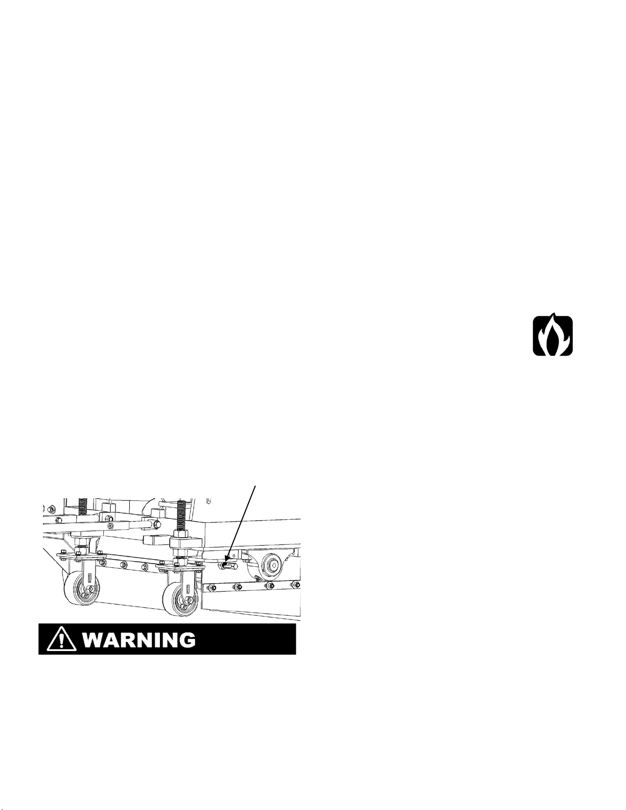
• Regularly clean any slurry, concrete dust, and
debris from saw.
• Place jack stand or locks under
both frame edges at the front and
back of the saw frame when
working under saw.
• Repair saw immediately if problems arise.
• Replace saw decals when they have become
damaged or unreadable to ensure proper safety
and operating procedures.
• Dispose of all hazardous waste and materials
properly according to city, state, and federal
regulations.
• Always have a phone nearby and locate the
closest fire extinguisher and first aid kit prior to
saw operation.
• Persons under the statutory age limit should
not operate the saw.
• Always allow saw to fully cool when finished
operating in order to prevent burns or injury.
DO NOT:
• Operate the saw without a complete
understanding of all safety, operations,
and maintenance instruction.
• Drop equipment, supplies, tools, blades,
etc. when handling to prevent injury.
• Operate machine without using
appropriate safety equipment required for
work site task.
• Operate or service machine with clothing,
hair, or accessories that are loose and
may become entangled in machine.
• Operate using attachments not associated
with or recommended for the machine.
• Operate machine with loose fasteners or
belts.
• Operate machine with anyone in working
area.
• Operate machine until obstruction have
been removed from worksite
• Operate machine when ill, fatigued, or
under the influence of drugs or alcohol.
• Operate the saw on extreme slopes.
.
• Operate saw without any safety guards,
access panels, or safet y devices removed or
tampered with.
• Grease or lubricate engi ne o r components
while it’s running.
• Perform any maintenance until saw has
cooled.
• Perform maintenance with engine running.
Battery Safety
• Ignitable explosive gases are
emitted from battery. DO NOT
expose battery to sparks or open
flame.
• Keep are around battery well ventilated.
• Keep the battery level when handling it.
• Use protective eyewe ar or a face shield and
avoid contact with the skin when
handling/servicing the battery.
• Use a proper battery tester whe n testing the
battery strength.
• Always connect the battery cables to the proper
terminal to ensure safety.
• Regularly inspect the battery, cables, clamps,
and terminals for damages. Clean, replace,
tighten, and grease components as necessary.
• Always keep the battery cable clamps away
from the battery terminals when the battery is
disconnected to avoid a cciden tal connections.
• Immediately rinse your clothing, skin, or eyes
with water if exposed to battery acid. Seek
medical attention immediately!
• Turn off the master battery disconnect when
servicing the machine.
• Disconnect the battery prior to servicing the
machine unless stated otherwise.
• Remove the battery when storing the machine
for longer periods.
• Disconnect external eq u i pment connected
through the electrical o u tlets prior to servicing
the machine.
• Always use the correct size fuses (amps) to
prevent fires.
Blade Safety
• Always use reinforced abrasive blades or steel
centered diamond blades.
• Inspect all blades prior to usage and discard
any damaged blades.
• NO NOT install a blade shaft with engine
running.
• Keep all body parts away from rotating blades.
Page 6

Blade Safety cont.
• DO NOT Expose yourself or others to the direct
line of the blade shaft while operating the saw.
• Inspect the blade flanges, for any visible
damage, wear, and cleanliness.
• Always use the appropriate si ze blade for the
cutting task. The blade must fit snug on the
blade shaft arbor and be properly retained by
all blade shaft tie bolts and flanges.
• Wear gloves and always be aware of
environment when handling blades.
• DO NOT drop blades when handling.
• Always point printed arrow on the blade in the
direction the blade shaft is rotating when
installing blade.
The CG-2 is
an Up Cut machi ne ,
therefore the blade arrows
must point toward the
operator if they were at the rear of the
machine.
• Always use the appropriate blade type for the
material being cut.
• DO NOT exceed the maximum RPM speed
printed on the blade when cutting; Excessive
blade speed can cause blade breakage,
resulting in serious injury and/or death.
• DO NOT use blade with lower maximum
operating speed than the blade shaft speed for
cutting.
• Always tighten the blade shaft bolts to 185 ft-lb
or 250 Nm to properly secure the flange and
blades. Failure to completely secure the loose
flange or blades may cause parts to loosen or
fall off resulting in serious injury and damage to
machine.
• Install correct blade shaft sheave, drive belts,
and flanges when changing blade size. Refer to
the Diamond Products parts list in this manual
for additional information.
• Adjust engine speed if necessary to properly
accommodate the indicated blade speed which
can be identified by the readout on the shaft
speed tachometer located on the dash.
• Raise the blade to a sufficient height when
maneuvering the saw to provide proper
clearance between groun d and blades.
• Always allow blades to cool prior to servicing,
blades may get extremely hot during cutting
process and may retain heat for long periods of
time.
Belt Guard Safety
• DO NOT Operate saw without belt guards in
place.
• Blade exposure while cutting should be no more
than 180°.
• DO NOT remove belt guards with engine
running.
• Always keep belt guards in place and securely
fastened to prevent danger.
• Inspect the belt guard prior to operating and
clean, repair, or repl a ce as neces s a r y.
Fuel Safety
• Store all fuels in appropriate safety containers.
• DO NOT operate saw with a fuel leak.
• DO NOT refuel machine while it is running.
• Let engine cool before add i n g fuel.
• DO NOT smoke or expose fuel to
open flame when filling the fuel
tank and or working on machine.
• DO NOT overfill fuel tank, and
immediately cleanup any fuel spilled prior to
starting machine as fuel may leak from vent
cap when saw is raised.
• Move the saw away from fueling area prior to
starting engine.
• Use appropriate diesel f uels i n co ld weather
areas.
• Drain fuel tank and fuel lines for prolonged
storage.
Engine Safety & Starting Procedure
• Refer to the Deutz Operational Manual including
with this saw for primary engine safety and
care information.
• Push the
immediately stop the engine if necess a r y.
Starting Procedure
• The CG-2 machine is equipped with multiple
safety devices to prevent injury to operator
or equipment during startup and operation.
• Always start the engine with the speed
control lever in
transmission fully engaged to prevent
unnecessary saw movement.
• To engage the transmission, locate the
Positraction Engagement Knob on the dash
of the machine and tighten until transmission
is fully engaged.
• Water pressure must be present at the water
supply connection in order to start the
machine. The CG-2 machine is equipped with
Emergency Stop
NUETRAL
button down to
and the
Page 7
a water safety device that prevents saw
operations without having an adequate
water supply. Water does not necessarily
need to be flowing to cutting head, but must
be pressurizing in the system and must be
utilized when sawing.
• The CG-2 Grooving and Grinding machine is
also equipped with a safety device that will
not permit an engine start unless the cutting
head is fully raised and the saw blades are
completely clear of ground. This is achieved
by raising the cutting head FULLY by
pressing the left button on the controller
handle and raising the cutting head till it
stops.
• Set the parking brake located on the left side
of the machine to the ON position.
• The machine may now be started using the
key switch located on the dash panel.
• Once engine has been started and given
adequate time to achieve operating
temperature the saw is ready for use.
• Remember the transmission must be fully
engaged or a safety device will not allow
lowering of the cutting head.
• Slowly lower the cutting head using the right
button on the control lever use caution not
to slam the cutting head blades into the
ground.
• Also be sure that the rotating safety shield is
rotated out of the way and locked in to
position using the pin on the lower left of the
machine.
• THIS MACHINE IS AN UP CUT SAW,
MEANING THE BLADES ROTATE IN A
DIRECTION CAUSING THE MACHINE TO
FORCE ITSELF BACKWARDS. USE CAUTION
WHEN FIRST ATTEMPTING TO CUT TO
PREVENT SERIOUS INJURY TO OPERATOR
AND EQUIPMENT. BE AWARE OF THE
EMERGENCY STOP BUTTON LOCATED ON ---
-THE DASH IN ORDER TO PRESS IT IN CASE
MACHINE BECOMES UNCOTROLLABLE.
• Once machine is set to depth and ready to
cut, disengage the parking brake and
proceed to cut with caution by moving the
controller handle forward.
• DO NOT leave machine unattended when
running.
• Keep all body parts away from rotating parts
when the machine is running.
• DO NOT start engine without air filters installed.
• DO NOT allow dust or debris to enter air intake
tubes when cleaning/servicing air filters to
prevent serious engine damage.
• Replace any damaged saw components
immediately that may allow dust to enter the
engine in order to prevent serious engine
damage.
• DO NOT use any starting substances or fluids
when starting engine using glow
plugs. (Spraying st arter into
intake tube) These materials are
extremely flammable and
explosive, and can melt or damage parts
possibly causing engine to explode when used
in conjunction with glow plugs.
• Always operate saw in a well ventilated area.
Concentrated engine exhaust can cause loss of
consciousness and/or death.
• DO NOT operate saw in areas that contain
combustible materials and/or fumes, these can
create and explosio n.
• DO NOT leave saw unattended after shutting
off until blades have fully stopped spinning.
• Clean the engines cooling system regularly to
prevent hot operating temperature and damage
to saws engine.
• DO NOT perform any maintenance on saw
while it is running.
• Let engine cool before performing any
maintenance.
• Handle hot oil carefully when changing oil and
make sure to properly dispo se of used oil.
Cutting Safety
• The work area should contain no buried or
embedded electrical, gas, water, or
telecommunications lines.
• Turn off all electricity, gas, and water lines
around work area prior to cutting.
• DO NOT expose yourself or others to the direct
line of cutting when operating saw.
• DO NOT allow any person, animal, or object in
and around work area when cutting.
Page 8
• Use just enough pressure to guide the saw on
6
cutting line. DO NOT forcibly direct (twist) the
saw from side to side to avoid damaging the
saw blades.
• Avoid sawing excessively deep to prevent
premature blade wear and reduce sawing cost.
Hydraulic System Safety
• Turn the engine off prior to performing and
maintenance on the hydraulic system.
• Lower the saw to the floor so it is level to
release pressure in the hydraulic system prior
to performing any maintenance on the
hydraulic system.
• Visually inspect for, or use a piece of cardboard
placed under machine to check
for and locate and hydraulic
leaks. Keep all body parts away
from areas were that may eject
hydraulic fluid. Pressurized hydraulic fluid can
penetrate skin causing serious injury.
Belt Safety
• Turn off engine prior to performing any belt
maintenance.
• Always let belts cool down prior to performing
any replacement or repairs.
• Regularly inspect the belts for any fraying,
stress cracks, and /or any other damage,
replace them immediately if and damage is
found.
• Over tensioning the belts may cause damage to
the PTO unit. Under tensioning belts may cause
shorter belt life and poor saw performance.
• Squealing belts are an indication that the belts
are loose.
• Always make sure that belts are properly
aligned.
• Always replace belt guard prior to operating the
saw after any belt maintenance.
Transmission Safety
• DO NOT assume the transmission will act as a
brake or holding mechanism when the saw is in
Neutral
the
saw. Block the saw to prevent an unwanted
movement and set the parking brake on the left
side of the machine.
• The engine must run at half throttle or greater
to ensure proper transmission efficiency.
• Clean the transmission fan and fan guard
regularly and prevent buildup of debris on the
transmission to prevent high transmission
temperatures.
position when stopping or parking
Transportation Safety
• Drain the saws fuel tank when transporting
over long distances.
• Use heavy duty ramps that will support
weights greater than the saw and operator
for loading.
• The towing vehicle/trailers should always be
in good working condition and capable of
handling the weight of the machine.
• Raise the saw to avoid catching the lower
body of the saw when loading and
unloading saw.
• Use extreme caution and low speed when
guiding saw up or down ramps for loading.
• Slowly drive the saw backward up the
ramps and slowly forward for unloading
down ramps.
• When transporting saw, turn engine off
once the saw is loaded and place the drive
level in the
Neutral
position and engage the
transmission.
• Block and chain the saw to properly secure
it for transport, do not assume the
transmission and parking brake will keep
the machine in place.
• Refer to DOT (Department of
Transportation) for additional information
regarding proper transportation technique.
Lifting Safety
• Move yourself and others
away from the lifting area
when hoisting to prevent
being crushed underneath
saw.
• Secure the appropriate cables, ropes, wires,
and/or chains to the saw lifting points and
frame to properly lift saw when hoisting it.
• DO NOT attempt to lift saw irresponsibly or
improperly.
Page 9
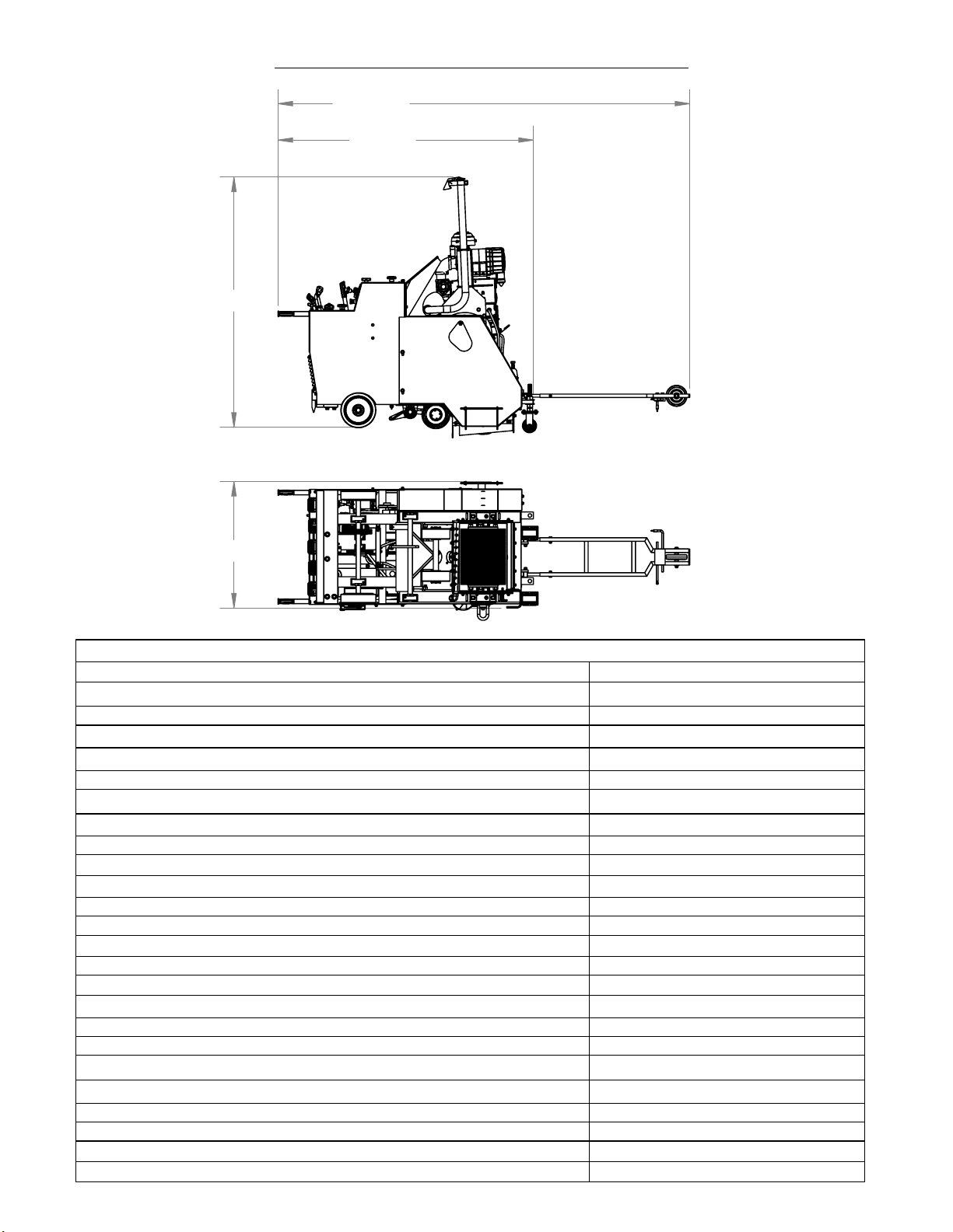
72.000
7
CG-2 Mini Groover Dimensions
118.000
73.000
36.000
Saw Specifications
Maximum Length (Pointer Down and Handles Extended)
Minumum Length (Handles in and Pointer Up)
Saw Height
Handle Extension
Saw Width (Maximum)
Uncrated Saw Weight
Blade Arbor Diameter
Maximum Cutting Depth
Blade Shaft Bearing Diameter
Blade Shaft Bearing
Blade Shaft Drive
Blade Shaft Effective Length
Blade LIft
Blade Coolant
Front Wheels
Drive Wheels
Handle Bars
Transmission
Drive Speed
Electric Start
Hour Meter
Amp Meter
Fuel Capacity
Blade Tachometer
Frame Lift
142.00"
73.00"
72.00"
24.00"
36.00"
1900-2000 lbs.
5.00"
1.625"
1.4375"
High Capacity Tapered Roller
Dual 5 Groove 3V Belts
16.00"
Electro-Hydraulic Pump
10 H1/4 Spray Nozzle
8.00" x 3.00" x 1.00"
10.00" x 3.00" x 1.25"
Two Positions with Tilt
Eaton Hydrostatic
0-200 Ft/Min
Standard
Standard
Warning Light
9.0 U.S Gallons
Standard
Standard
Page 10
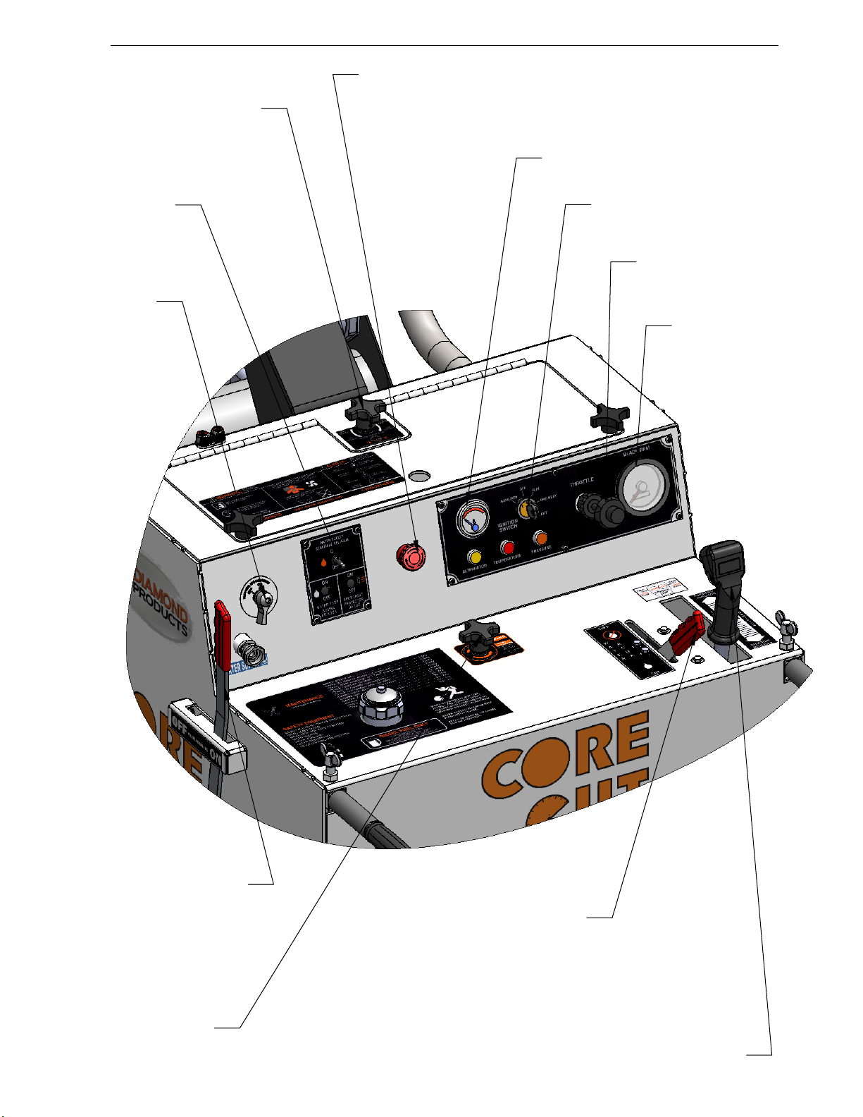
CG-2 MIni Groover Dash Layout & Operational Controls
8
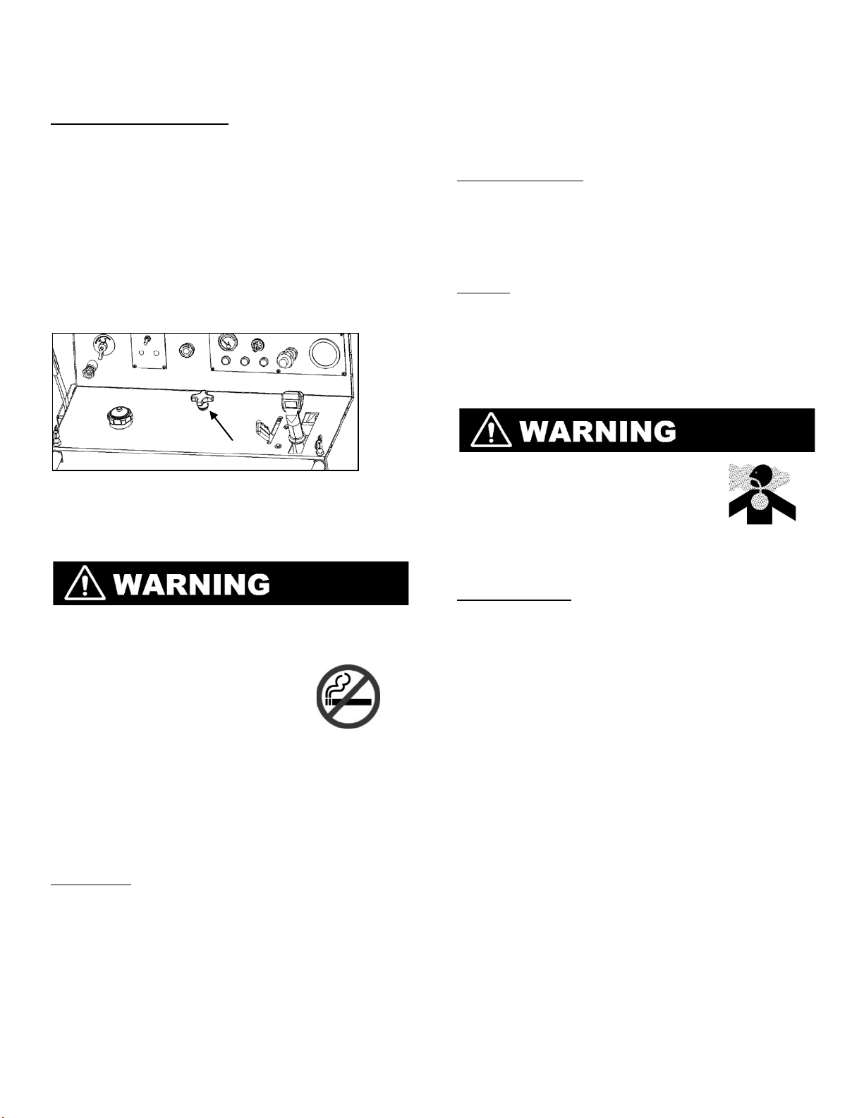
Blade Depth Stop Control:
Holds specific cutting depth.
Emergency Stop:
Stops all power systems
inside of machine in case
of emergency.
Water Safety Switch:
Ensures water pressure
to machine.
Master Power Switch:
Controls Electrical output
from battery to components
electrical systems.
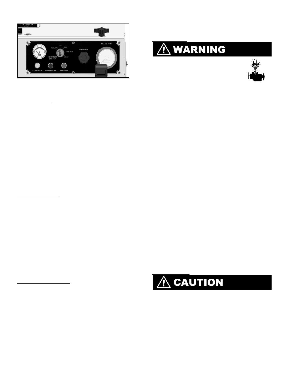
Engine Temperature Guage
Ignition Switch
Throttle Control:
Used to sets engine RPM.
Shaft Tach:
Accurately monitors
blade shaft RPM, and
indicates total hours of
saw operation.
Parking Break:
When engaged prevents
machine from moving.
Positraction Control:
Used To engage drive
axle to transmission.
Water Control Lever:
Used to engage water flow to
cutting head.
Control Lever:
Forward & Reverse motion controls
machine movement in corresponding
direction while in center is neutral. Left
button controls raises blades, and right
button lowers blades.
Page 11
Operating the CG -2
9
Handlebars
The handlebars are used to help the operator guide
and maneuver the saw.
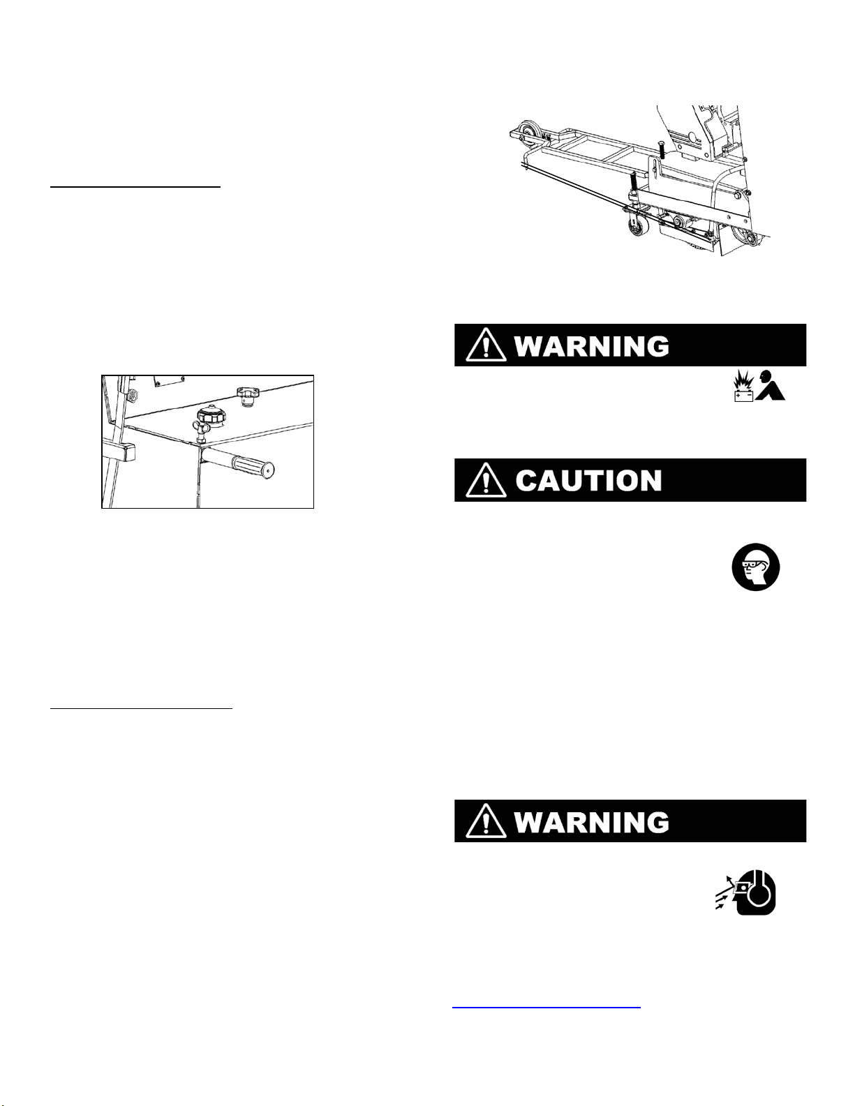
Adjusting the Handlebars
1. Loosen the handle lock knobs.
2. Hold the handlebar grip and place the first
handlebars into the handlebar opening
directly below the lock knob , there are two
paths the handlebar can fit through. Select
the handlebar angle that works best for
specific cutting ope r a tion and slide
handlebar in to determined length.
3. Tighten the handle lock knob to secure
handlebar at proper position.
pointer lanyards and place it in the cable
cleat to secure it in place.
Pointer Alignment Using String
Battery
• Ignitable & explosive gasses
are emitted from the battery.
DO NOT expose battery to any sparks or
open flames, and keep are around battery
well ventilated.
Handle Lock Knob & Handlebar
4. Repeat steps 2-3 to secure the second
handlebar.
5. Adjust handlebar orientation and length as
necessary.
Front Pointer
The front pointer assembly aids the operator in
following a cutting line.
Adjusting the Front Pointer
1. Remove the tensioned pointer lanyard from
the cable cleat on the top of the dash.
2. Lower the front pointer to the floor.
3. Loosen both front pointer frame screws.
4. Divide a 10’ piece of string in half.
5. Place the looped end of the string into a
gullet on the backside of the outermost
blade.
6. Place one side of the string up against the
front side of the blade, holding the string
ends in one hand; tension the lines out
towards the front pointer rod.
7. Slide the pointer rod over between the
tensioned string lines.
8. Retighten both front pointer frame screws
to secure pointer rods .
9. Lift the front pointer frame off the ground
when cut is complete, and re-tension
• Use proper battery tester, such as a
voltmeter, to test the ba t te ry stren gth.
• Use protective eyewe ar or face
shield and avoid skin contact
when handling battery.
The saw contains an installed, charged battery with
one positive and one negative battery lead. The
battery cables are connected prior to saw delivery.
A battery disconnect switch is located o n the left
side of the dash on the saw, this disconnect switch
should be used whenever the saw is not in
operation for safety and battery longevity.
Diamond Blades
DO NOT Exceed the maximum RPM printed on the
blade when cutting. Excessive blad e
speed can cause blade breakag e ,
resulting in serious injury or death.
Using the proper blade helps preserve the blades
life and also improves the operator’s efficiency,
resulting in lower cost. Refer to
www.diamondproducts.com for a list of all the
different blades available to suite each job.
Page 12
10
Inspecting the Blade
Always inspect each blade prior to blade
installation. DO NOT use damaged blades for
cutting in order to avoid injuring yourself, others,
or the machine. Discard all damaged blades and
inspect each replacement blade for deficiencies.
Inspect blades prior to installation for:
• Cracks, Nicks, Or Dents
• A damaged and/or deformed arbor.
• Darkness or discolo r ati on near edges of the
blade.
• A deformed blade circumference.
• Segments missing or cracked.
• Core wear.
• Bending or warpage.
• Uneven side widths.
Blade Speed
Refer to the Diamond Products blade specification
for information on the recommended blade RPM
when cutting. DO NOT use a blade with a lower
maximum operating speed than the blade shafts
speed when cutting.
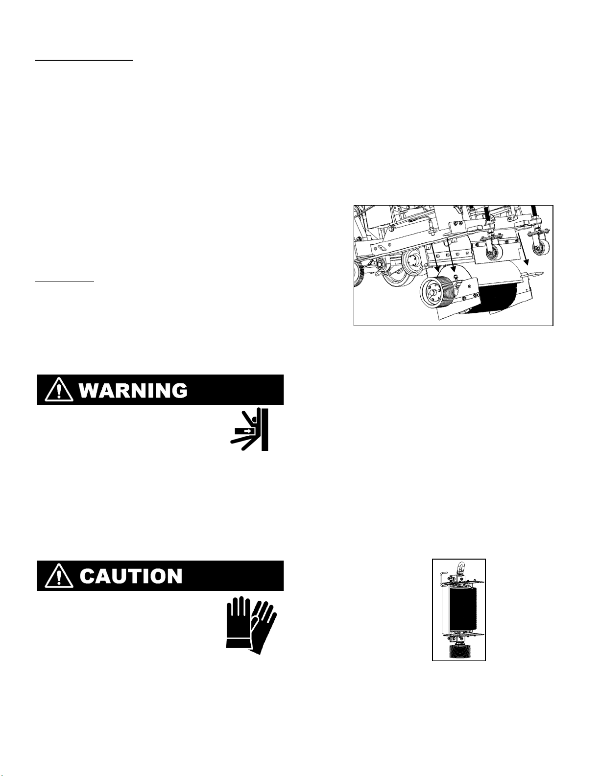
Blade Shaft Removal
• DO NOT remover or install a
blade shaft with the engine
running.
• Failure to properly s e cure th e
loose flange and blade shaft tie bolts may
cause parts to loosen and fall off.
• The blade shaft assembly weighs up to 500
pounds and must be lifted to a vertical
position to change blades.
• Failure to follow these instructions may
cause serious injury or death.
3. Lower the saw until the blades make
contact with the ground using the lowering
button located on the right side of the
control handle.
4. Block the front and rear of the blade shaft
assembly with wooden block or similar to
ensure the blade shaft assembly does not
roll when bearing bolts are loosened.
5. Remover the depth stop wheels off the
front of the machine by removing the hex
nuts with a 1.50” wrench or socket.
6. Loosen and remover the 4 blade shaft
bearing bolts using a 3/4” wrench or socket.
Carefully Lower Blade Shaft Assembly From Machine
7. Slowly raise the saw to the maximum height
using the raise (Left) pushbutton on the
speed lever.
8. Carefully remove chock blocks at the front
of the blade shaft assembly and slowly
remove the assembly, it should clear the
machine.
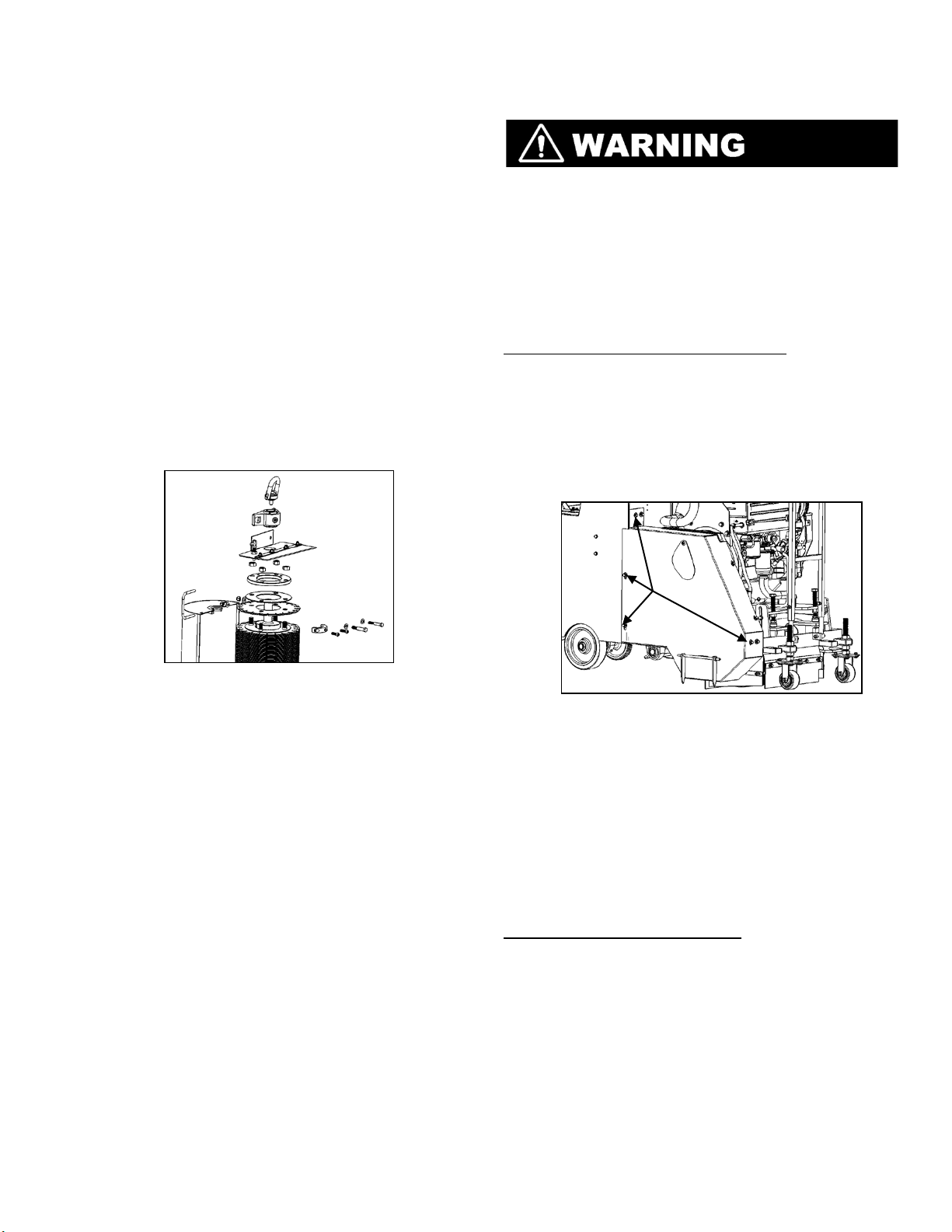
9. Using supplied hoist ring (2504720)
attached to the non sheave end of the
blade shaft. Make sure the ring is fully
seated in the threads and that threads are
clean and free of debris on the end of the
blade shaft. With a suitable lifting device
and proper capacity chain or cable, lift the
shaft and carefully set down on sheave end.
After securely setting in upright position,
remove hoist ring.
• Always wear protect ive glo ves
when handling blades.
• Always let blades cool prior to
removing or replacing of
blades.
Place Blade Shaft Assembly on End Using Hoist Ring
1. Remove the belt guard. There are 6 bolts
that must be removed using a 9/16”
Wrench or Socket.
2. Remove the blade shaft driv e belts (2).Refer
to page __ for removal and installation.
10. Remove the revolving blade shield by
removing the hex head machine screws
located on the underside of the shield near
the bearings.
Page 13
11. After bearing cap halves are removed,
11
remove outer shield and set as ide.
12. Remove the bearing on the lifting end of
the blade shaft and set aside.
13. Next, remove the Left Blade Cover
Weldment leaving the water shield and lock
pin attached.
14. Remove the (4) Hex nuts using a 1-1/8”
wrench or socket holding the Blade Flange
in place.
15. If the Blade Flange is stuck, use the (4) pre
tapped holes to thread ½-13 bolts to press
off the flange.
16. Once the Blade Flange is removed you have
access to the cutting bl ades and spacers,
these will vary depending on the setup of
your saw. REMEMBER to inspect all blades
for any signs of damage including, cracks,
dents, missing segments or discoloration
and replace immediately.
Belt Guards
• DO NOT operate machine with belt guards
removed.
• DO NOT remove belt guards when engine is
running.
The belt guards shield the belt drive to prevent
accidents and must always be in place when
operating the saw.
Removal & Installation of Belt Guards
1. Remove the (6) 3/8” bolts using a 9/16”
wrench or socket that retain the belt guard.
2. Lift the belt guard away from machine.
NOTE: the belt guard shields the underside
of the pulleys and must be removed by
pulling straight back.
3. Install in reverse order of removal.
Blade Removal (Please Refer to the Parts Manual
Section of This Manual for Larger Illustration).
17. Repeat steps 10-16 in reverse order for
reassembly, take note that the blade shaft
spins at very high RPM’s and all fasteners
must be double checked for proper fitment
and torque (4 bolts retaining Blade Flange
must be 185 ft lbs or 250 Nm) prior to
reinstallation to ensure operator and
machine safety.
18. When installing new blades, be sure the
blades are correct for the cutting task.
19. Cleanliness is very important in this area of
the machine, take the extra time to ensure
all debris, slurry and foreign materials have
been fully eliminated b e fore r ea ssembly.
20. Always make sure the arrow on your
Diamond Products blade is pointed in the
same direction as the rotation of the blade
shaft.
21. Reinstall blade shaft assembly in the
reverse order of removal; reinstall belts,
guards and depth stop wheels before
restarting machine.
Remove the six bolts attaching belt guard.
Water Supply
The water supply helps cool the blades and
minimize dust when cutting. Approximately five to
eight gallons of water per minute are required to
adequately cool blades when running.
NOTE: this
machine is equipped with a water safety switch
meaning it will NOT operate unless there as a
suitable supply of water to the water supply line.
Using the Water Supply System
1. Connect water source to the hose
connection on the left side of the dash of
the machine.
2. Turn on the Water Safety Switch on dash
panel.
3. When ready to start cut, turn the water flow
to the ON position using the level next to
the Machine Control Handle on the right of
the dash. Remember the water source
needs to be ON and adequate in order for
the machine to be started.
Page 14
4. There a total of ten spray tips routed just
12
behind the blades of the cutting head, these
ensure proper cooling when cutting.
5. Check that the spray tips with machine off
that they are functioning properly and have
an even spray of water when servicing
machine.
Control Grip
The control grip located on the right side of the
dash control many of the functions of the machine.
Moving the lever in a forward and reverse motion
control the machine movement in a similar fashion,
while in the center position is neutral.
NOTE: even
though the machine will typically not move in the
neutral position, do not assume it is safe to hold
the machine in a parked manner, always use the
parking brake to park machine.
There are also two
button located on the front side of the control
lever, these operat e the raisi ng and lo weri ng of the
cutting head. The left button raises that machine,
while the right lowers the machine.
Control Grip Lever
Raising the Saw
Press the left button on the control grip to raise the
saw and depress to stop.
NOTE: Always raise blade
to s sufficient height to ensure the blades are
completely clear of the ground when maneuvering
the machine.
Lowering the Saw
Press the right button on the control grip to lower
the saw and depress to stop.
NOTE: Carefully lower
the saw, do not slam the cutting head down, this
may damage blades or the machine.
Controlling Lowering Speed
It is possible to adjust the rate at which the
machine lowers the cutting head, to do this make
sure the machine is shut off and remover the rear
access panel form the machine. With panel
removed adjust the flow control valve located on
the hydraulic pump so it is to the operators liking.
Flow Control Valve
Forward Control
Push the control lever forward to travel forward ate
desired speed. The maximum speed that the saw
can travel is 200 ft/min.
NOTE: The engine must be
running and the transmission must be fully
engaged in order to move the usin g the speed
control lever, which must be in the NUETRAL
position to start engine. Also remember that the
emergency STOP button will always stop the
machine should it be necessary.
Reverse Control
Pull the speed control l ever backward to the
desired traveling speed. The maximum speed the
machine will travel backward is 200 ft/min.
Neutral Control
Place the speed control lever in the Neutral position
to stop the saw from moving forward and
backward. DO NOT use the neutral position as a
parking brake, this will NOT hold the machine;
apply the parking brake to keep machine from
moving unnecessarily.
Transmission
The transmission controls the movement of
machine. Always remember to push the em ergency
STOP button to immediately stop the saw if
necessary. The transmission must be engaged and
in the neutral position in order to start the
machine, as a precaution always have parking
brake set when starting the machine.
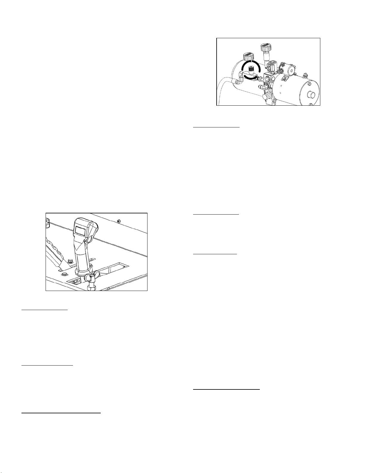
Engaging Transmission
1. Place speed control leve r i n the neutral
position.
2. With engine off, turn the Transmission
Engagement Knob located in the center of
the lower dash to the left to engage
transmission.
Page 15
3. Turn knob till its stops, this ensures that
13
transmission is engaged.
Disengaging Transmission
1. Place speed control leve r i n the neutral
position.
2. Locate Transmission Engagement Knob in
the center of the dash.
3. Turn Engagement Knob to the right to
disengage transmission
4. Transmission is disengaged when machine
will free roll. NOTE: DO NOT disengage
transmission unless saw is on level ground
and parking brake is set.
Transmission Engageme nt Knob
Fuel System
• DO NOT operate the saw with a fuel leak.
• DO NOT refuel saw with the engine
running.
• DO NOT smoke or expose
fuel to open flame when
filling the fuel tank and/or
working on fuel system.
• DO NOT overfill fuel tank. Cleanup any
spilled fuel prior to starting the machine.
• NOTE: Fuel may seep from fuel vent cap
when saw is raised to its upright position if
overfilled with fuel, cleanup any fuel
spillage.
Adding Fuel
Check fuel level daily and fill as necessary, avoid
running machine out of fuel.
1. Lower the saw so that it is level with
ground.
2. Stop the engine and allow time to cool
down.
3. Remove fuel cap.
4. Fill the fuel tank with low sulfur or ultra low
sulfur diesel fuel only. The fuel tank has a
capacity of nine gallons.
5. Replace fuel cap and tighten to secure.
Cold Weather Fuel
Diesel fuel can become thick in cold weather,
resulting in clogs in the fuel system; refer to the
Deutz Operation manual for a list of appropriate
cold weather fuels.
Storage
Fill the fuel tank to prevent condensation and
contamination in the tank for short storage
intervals. For long periods of storage, drain the fuel
tank and lines.
Engine
• DO NOT leave engine running
while machine is unattended.
• Operate saw in a well
ventilated area, co ncen trated
exhaust can cause loss of consciousness
and/or death.
Engine Governor
A manufacturer set governor controls the engines
maximum speed. DO NOT adjust the governor
setting unless blade size has changed and would
require a different maximum engine speed.
Ignition Switch
The ignition switch is located on the dash panel of
the CG-2 machine. This is a multi-function switch
and operates as follows:
Auxiliary:
•
the engine.
• Off: Turns engine off.
Run:
•
engine.
•
Pre-Heat:
help the engine start in cold weather.
•
Start:
Creates power, but does not start
Creates power, but does not start the
Warms engines glow plugs which
Turns engine on.
DO NOT engage
Start for long periods of time, this can
cause overheating or damage to the starter.
If engine does not start right away, release
the key and try several minutes later. Refer
to the Fault Table in the Deutz manual if
engine does not start after two attempts.
Page 16
14
Ignition Switch & Throttle Handle
Throttle Handle
This controls the engines RPM, which in return
control the blade RPM which in monitored on the
Blade Tachometer located next to the Throttle
Handle. NOTE: The Tachometer on the dash DOES
NOT indicate engine RPM, this is a measure of
blade RPM.
• Turn the throttle handle counterclockwise to
increase the engines RPM ’s. To decrease
engine RPM’s turn the throttle handle
clockwise.
• Push the spring loaded throttle tip and pull
the throttle out to increase engine RPM’s, or
push in the throttle handle to decrease
engine RPM’s.
Hold/Release Knob
• Turn the Hold/Release knob clockwise to
hold the throttle at a constant engine/blade
RPM or turn the Hold / R eleas e knob
counterclockwise to r e l ea se the throttle and
adjust engine RPM.
• Turn the Throttle Handle clockwise to
decrease, or counterclo ckwise to increase
engine/blade RPM when the Hold/R el e ase
button is secure; however, the spring
loaded throttle tip cannot be pushed in or
pulled out to adjust engine/blade RPM when
the Hold/Release button is secured.
Prior to Starting Engine
Complete the following check list prior to starting
the engine.
• Fill the fuel tank with diesel and check the
engine oil.
• Push the water valve to OFF position
• Make sure Water Safety Switch is ON
• Place transmission in NEUTRAL
• Engage transmission
• Apply Parking Brake
• Pull Emergency Stop OUT
• Verify the Master Power Switch is ON
• Push the Throttle in to idle.
• Remove all obstructions from work area.
Starting Engine
• DO NOT use any starting
substance or starter fluids when
starting machine. Engines
equipped with glow plugs may
ignite these extremely flammable materials
and may spark fire or explosion causing
serious injury and/or damage to machine.
1. To start engine without using glow plugs,
insert the key into the key ignition and turn
Start
the key to
, and immediately release
when engine starts. If engine does not start
after two attempts, refer to the Fault Table
in the Deutz Manual.
2. To start the engine using glow plugs, insert
the key into the key ignition and turn the
key to
Pre-Heat,
holding it there for
approximately 20 seconds. Turn the key to
Start
the
position and release immediately
after engine start. If the engine does not
start right away, try the
again and attempt to
Start
Pre-Heat
process
engine. If engine
does not start after two attempts refer to
the Fault Table in the Deutz Manual.
3. Once engine has started increas e engine
speeds to half throttle and allow the engine
to warm up for several minutes.
4. Increase the engine speed to full throttle
after warm up. Adjust throttle as necessary
when cutting. DO NOT exceed
recommended blade RPM.
NOTE: At times
the actual blade RPM will be lower than that
recommended for the blade do to job
conditions and/or task difficulty level.
Stopping Engine
• DO NOT leave the saw unattended, after
turning off engine until blades have fully
stopped spinning.
1. Place speed controller in
Neutral
position.
2. Raise blades from cut.
3. Push water valve to OFF position.
4. Decrease engine speed to i dle for several
minutes to allow engine to cool down.
OFF
5. Turn key to
position and remove key.
Page 17
Concrete Cutting
15
• DO NOT expose yourself or other in
the direct path of the
blades when operating
the saw.
For better efficiency, keep the foll o wi ng in mind
while cutting:
• Use just enough pressure on the handlebars
to guide the saw on the cutting line. DO
NOT forcibly direct (twist) the saw form side
to side when cutting.
• Moving too quickly when cutting may stall
the saw, or cause the blades to climb out of
the cut. If the saw stalls at anytime, move
the speed controller to the
Neutral
and raise the blades fully to restart the
engine.
• DO NOT lower the blades or move the saw
forward to quickly when finishing a partial
cut to avoid forcing the blades into the
concrete.
Prior to Cutting
Complete the following prior to cutting:
• Raise the blades to a sufficient height
when maneuvering the saw to provide
proper clearance between machine and
the ground.
• Align the front pointer with the blade.
• Clearly mark the cutting line.
• The work area should not contain any
buried cables, electr i ca l l ines, gas lines,
or telecommunication lines and all gas
and electrical utilities should be shut off
in area prior to cutting.
Making the Cut
1. Pull the water valve to the
ON
2. Align the blade and pointer with the cutting
line.
3. Lower the blade to touch the cutting
surface.
4. Plunge the blade until the desired cutting
depth is reached. To maintain a particular
depth when cutting, turn the Depth Control
Knob clockwise, located on the top of the
machines dash, until resistance is felt. The
blade should not lower any further, if there
is no need for a depth stop, do not use it.
5. Push the speed control lever forward until
the desired travelling speed is reached .
position
position.
Raise and lower the blades as necessary.
When using the depth stop, raise the blades
from the cut and repeat as necessary.
Adjusting the Depth Stop
Turn the depth stop knob counterclockwise to
increase the cutting depth when plunging the
blade, or turn the depth stop knob cloc kw i s e to
decrease the cutting depth when plunging the
blade. The depth stop knob will stop turning when
the saw has reached its maximum depth.
Depth Control Knob
Continuing a Partial Cut
1. Maneuver the saw into the correct location.
2. Align the blade with previous cut, and then
plunge the blade back into t h e co n cr ete. DO
NOT move forward until blade is properly
aligned with cut.
3. Push the speed control lever forward until
the desired travel i ng speed is reached.
Finishing a Cut
1. Place the speed control lever in the
Neutral
position.
2. Raise the blades from the cut high enough
to ensure proper ground clearance when
maneuvering saw.
Page 18

Maintaining the CG-2
16
DO NOT attempt to perform any maintenance on
this saw if you are not properly trained for it, or are
not supervised by an experienced p erson. Contact
the manufacturer with any questions regarding the
maintenance. Refer to the Diamond Products Parts
list contained in this manual for additional
information, part numbers, and assembly diagrams.
Failure to read and comply with the instructions
provided in this manual may result in serious
injuries and/or death, and may cause damage to
the saw.
Complete the tasks listed below prior to performing
and saw maintenance:
• Turn the engine of and let the engine and
machine cool down.
• Turn all switches and/or controls to their
OFF positions.
• Disconnect the battery.
• Place jack stands or blocks under both
edges of the frame at the front and under
the frame base at the rear of the machine
when working underneath the saw.
Maintenance Overview
Complete the following maintenance task as
required. There is a maintenance chart decal
placed directly atop the machine on the dash panel
for you convenience. Refer to the Deutz
Operational Manual for full engine maintenance.
Daily and/or Regularly
• Lubricate the blade shaft bearings daily or
when dry cutting 2-3 times daily. The
grease fittings for the bearings are located
on either side of the blade shaft assembly.
• Lubricate the blade shaft cover bearings
daily, the grease fittings are located on the
inner edges of the blade shaft cover on
either side of the blade shaft end flanges.
• Inspect all belts daily for tension and wear,
and replace and/or re-tension them if
necessary.
• Visually inspect the saw for any signs of
damage, fluid leaks, or excessive wear.
• Tighten loose nuts and bolts.
• Check fuel level and fill if necessary.
• Check hydraulic fluid level and fill if
necessary.
• Check engine oil and fill if necessary.
• Remove all slurry and debris from the
cooling fan.
• Remove and slurry or debris from the oil
cooler.
• Re-tension the rear drive chain if necessary.
125 Hours
• Change Engine oil.
• Replace oil Filter.
500 Hours
• Replace in-line fuel filter.
• Replace fuel filter.
• Check battery, cables, and connectors and
clean if necessary.
• Replace outer primary air filter.
• Replace inner safety fil ter.
Handle Bars
The handle bars generally require little to no
maintenance. Check them occasionally for
abnormal bending or cracking and replace
immediately is there is any damage.
Part Lubrication
• DO NOT lubricate any part with the engine
running.
Lubricating parts on schedule increases the saw’s
efficiency and prolongs the saws life. Use NLGI
No.2 premium lithium based grease when
lubricating parts.
Blade Shaft
Lubricate both ends of the blade shaft daily, and 23 time daily when dry cutting.
Blade Shaft Cover
Lubricate both sides of the blade shaft cover daily.
Lift Plate Bearings
Lubricate the lift plate bearings and front axle
bearings every 40 hours of operation.
Page 19

PTO
17
Pump grease into the PTO grease fitting until it
begins to ooze out from behind the V-ring seal
every 25 hours. The grease fit ting is accessible on
the side of the belt guard, r otate access door to
locate fitting.
Rear Wheels
Inspect the rear wheels regularly for any visible
damages or wear and replace when necessary.
Replacing Rear Wheels
1. With the machine properly lifted and setting
on jack stands, unscrew the Trantorque
bushing and remove the rear wheel.
2. Place new wheel onto rear axle weldment.
3. Place Trantorque bushing into new wheel
hole and tighten bushing to 175 ft-lb (237
Nm). NOTE: Failure to properly tighten the
Trantorque bushing may cause the wheel to
fall off saw.
Battery Type
12 Volt, Group 24
Inspecting the Battery
1. Open access panel on top of the machine.
2. Loosen the battery brace l o c k nuts and
remove brace.
3. Disconnect the negative battery cable lead
form the negative battery terminal.
4. Disconnect the posit ive bat tery cable lead
form the positive battery terminal.
5. Inspect the battery terminals, battery
cables, and battery clamps for any visual
signs of damage, and corrosion and clean or
replace as necessary.
6. Reconnect positive battery cable to positive
battery terminal.
7. Reconnect the negative battery cable to the
negative battery terminal.
8. Replace the battery bra ce a nd locknuts.
9. Close access panel.
NOTE: If battery must be replaced, carefully
remove the battery from its platform and
remove it from the machine being careful to
keep it level. Properly dispose of old
battery.
Electrical System
Trantorque Bushing
Battery
• Ignitable & explosive gasses are emit ted
from the battery. DO NOT
expose battery to any sparks or
open flames, and keep are
around battery well ventilated.
• Disconnect the battery when performing
maintenance.
• Use a proper battery tester , such as a
voltmeter, to test battery and electrical
system.
• Use protective eyewe ar or a face shield and
avoid any contact with the skin when
handling the battery.
• DO NOT perform any electrical
maintenance with the battery
connected.
The electrical syst em generally requires litt le to no
maintenance. The fuses are located near the
hydraulic pump on the inside of the dash accessible
through the access panel. Replace fuses as
necessary.
The relay switch and circuit breakers are located
next to the fuse panel. The circuit breaker should
reset itself in the event of an overload, if the
breaker continually turns on and off, disconnect the
battery and determine the cause of the overload.
Magnetic Sensor
The magnetic sensor detects t h e blade shafts RPM
at the blade shaft and transfers the reading to the
blade shaft tachometer/hour meter. Generally this
sensor requires little or no maintenance, however,
if the blade tachometer/ hour meter remain at zero
Page 20

when operating the saw, the magnetic sensor
18
needs to be adjusted or replaced.
Magnetic Sensor Located Behind Blade Shaft Sheave
Adjusting the Magnetic Sensor
1. Loosen the jam nut on the magnetic sensor.
2. Turn the magnetic sensor clockwise until it
bottoms out (stops).
3. Turn the sensor counter clockwise exactly
one half turn.
4. Retighten the jam nut down the frame base
to secure sensor.
Replacing the Magnetic Sensor
1. Disconnect the battery.
2. Disconnect the magnetic sensors two wire
connector.
3. Loosen the jam nut on the sensor so it sits
near the upper part of the sensor, and turn
the sensor counter clockwi s e to remove it
from the base frame.
4. Place new sensor into the thread e d hole
and tight sensor till it bottoms out (stops).
5. Turn the sensor one half turn
counterclockwise and secure the jam nut on
sensor to frame base.
6. Reconnect the battery.
Air Cleaner
Refer to the Deutz Operation manual as the
primary source for information on the air cleaner.
Restriction Indicator
Service the air cleaner as de termined by the
restriction indicator to prevent unnecessary
damage to the engine, which decreas es
maintenance cost and prolongs the life the engine.
• The restriction ind icator service bar turns
red when the air cleaner requires service.
The chart on the restriction indicator
identifies the current restriction l evel in the
air cleaner.
• Press the reset button on the restriction
indicator to reset the unit after the air
cleaner has been serviced.
Restriction Indicator
Rubber Dust Ejector Boot
The rubber dust ejector boot valve ejects debris
and water when operating the saw. Occasionally
inspect and clean the ejector boot.
• Press inward on both sides of the ejector
boot near the valve opening to rele ase
debris and water, and clean the valve
opening when necessary.
Rubber Dust Ejector Boot
Cleaning/Replacing the outer Primary Filter
The air filter contains a dry outer primary filter.
Service filter accordi ng to the restriction indicator
bar, and replace the filter annually.
DO NOT over-service or under-service the filter.
DO NOT operate saw without filter installed.
1. Pull the tab out on the air cleaners end
cover.
2. Turn the end cap clockwise to unlock the
cover, and pull the end cover away from the
air cleaner.
3. Pull out the primary filter from the air
cleaner and inspect it condi tion.
4. Move away from the saw and clean the
filter form the inside out using dry
compressed air (no more than 70 PSI) and
wash lightly with water to remove all debris
from filter.
5. Allow filter to completely dry before reinstallation.
Page 21

6. Inspect the inside of the air cleaner
19
assembly. Clean away and loose debris
being careful not to get any debris inside
the intake tube.
7. Place filter back into air cleaner over safety
filter, and gently push into place till it feels
secure.
8. Place the end cap cover tigh tly back against
the end of the air cleaner housing and twist
clockwise and lock into place using tab.
Replacing the inner safety filter
The inner safety filt er i s not t o be cl ea ne d, replace
after five service cleanings of the primarily filter, or
every year. DO NOT operate saw without the
without this filter installed.
Air Cleaner End Cover Tab
Speed Control Lever
The speed control level genera l ly requires little
maintenance. If the speed control lever is out of
sync with the saws movement, for example, if the
saw moves forward when in neutral, adjustment is
needed.
Adjusting the Speed Control Lever
1. Remove the rear cover panel from saw and
identify the linkage assembly connected to
the speed control lever.
2. Adjust the threaded link between the ball
joint connectors.
3. Remove any tools from area and start
engine to check for accuracy .
4. Turn engine off and readjust if necessary,
then replace rear body panel.
5. If desired, loosen or tight the lock nuts on
the ball joints pivot point to adjust the
friction felt when moving the control l ever .
Linkage Assembly
Hydraulic System
• Turn off the engine prior to performing and
maintenance on the hydraulic system.
• Lower the saw to the floor so it is level to
release the pressurized hydraulic fluid in the
hydraulic system prior to performing and
maintenance or repairs.
• Visually inspect for, o r use a piece of
cardboard under machine, for
any hydraulic fluid leaks. Keep
all body parts away from areas
that may eject hydraulic fluid.
Pressurized hydraulic fluid can penetrate
skin causing serious injury. IF skin is
punctured by hydraulic fluid, seek medical
attention immediately.
Adding Hydraulic Fluid
Check the hydraulic fluid level regularly and add
when necessary.
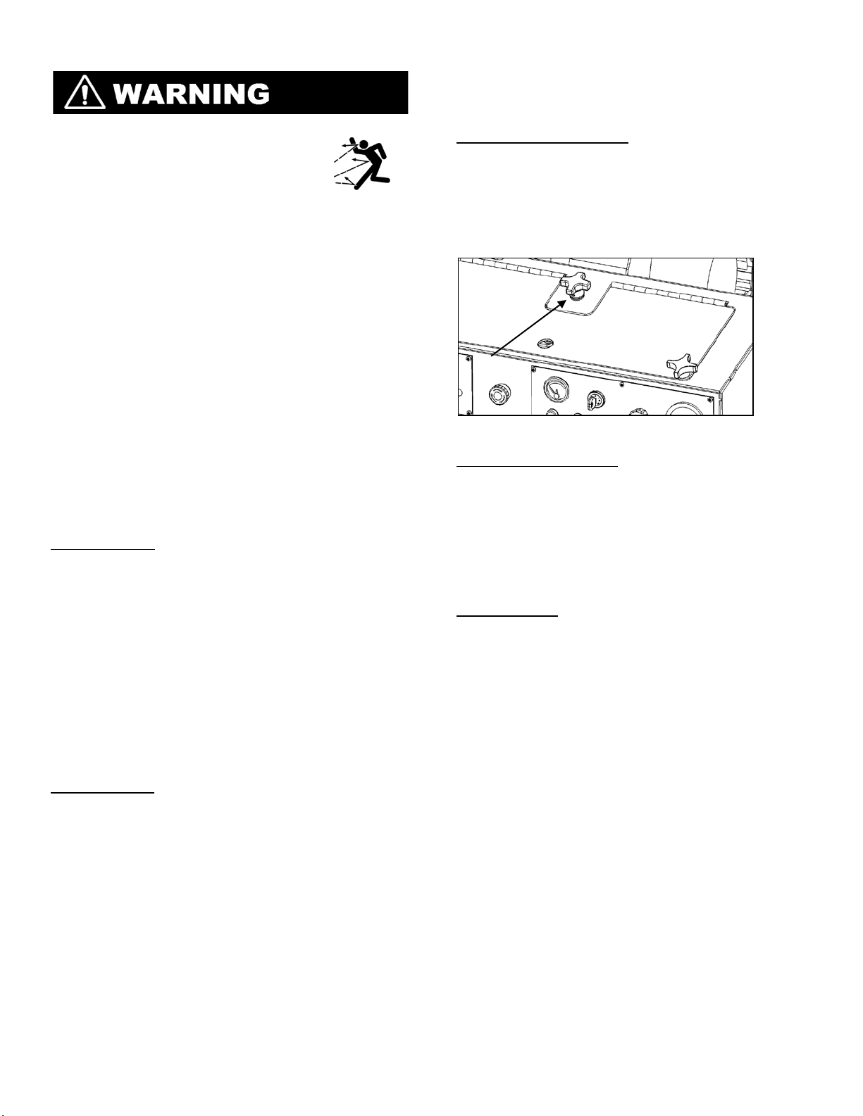
1. Open the access panel on top of the dash of
the saw.
2. Lower the saw to the ground so it is level
(this provides and accurate fluid level
reading).
3. Remove the breather cap on the top of the
hydraulic pump.
4. Add DEXTRON II automatic transmission
fluid when necessary.
NOTE: Filling the oil
to the top of the opening will cause fluid to
leak for the cap when the saw is lowered.
Fill oil to just below where the pipe begins
to extend out from the pump body to
prevent overfilling.
Page 22

Hydraulic Pump Breather Cap
20
Transmission
Cooling Fan
• Remove the fan guard and wipe down or
use compressed air to remove d ebris and
slurry form the transmission cooling fan.
The transmission will not properly cool if the
fan is clogged up with debris.
Adding Oil
• The hydraulic pump supplies oil to the
transmission. Check the oil level daily in the
pump and add DEXTRON II automatic
transmission fluid if necessary. Refer to the
previous section for information on adding
fluid.
Adjusting Rear Drive Chain
• Regularly inspect the rear drive chain and
tighten when necessary. Regularly lubricate
the rear drive chain with oil to increase the
chains life.
1. Remove the rear access panel from
machine.
2. Remover the chain guard.
3. Loosen the four 3/8” hex bolts and nuts
attaching the transmission to transmission
platform, but do not remove.
4. Adjust the set screw (3/8” bolt) that is
located on the front side of the transmission
platform.
5. Turn the set screw clockwis e to push
transmission backward in order to tighten
up chain slack. Leave a little slack in the
chain and DO NOT over tighten the chain.
6. Retighten the 4 transmission bolts and hex
nuts.
7. Replace chain guard and rear body access
panel.
Trans mission Adjustment Screw
Belt System
• Turn the engine off prior to
performing any belt
maintenance.
• Always let belts cool prior to
performing any belt maintenance.
Blade Drive Belts
There are two five-strand V belts that rotate the
blades shaft via the PTO.
Blade Drive Belt Tension
The manufacturer’s belt tension is s e t between 6870 hertz (Hz). DO NOT exceed the manufactures
tension settings. NOTE: Over-tensioning the belts
may damage the power-take-off (PTO) unit. Undertensioning the belts may cause premature wear
and/or poor saw performance. Squealing belts are
an indication that the belts are loose.
Test the belt tension on a daily basis to ensure best
performance and longest life of belts.
• Touch the end of the sonic tensio n me ter
sensor (Available through Diamond
Products) at the midpoint of the longest
section and strum the belt. Adjust the belts
tension if it is lower than the manufacturers
setting.
Adjusting the Belt Drive
1. Remove the belt guard.
2. Inspect belts for and fraying, stress cracks,
and/or breakage and replace immediately if
any damage is found.
3. Test the belt tension, Continue to step 4 if
the belt needs tensioning. R e place belt
guard if no tensioning or replacement is
required.
4. There are two ½-13 retaining bolts on the
front sides of the engine plate. Loosen
Page 23

these bolts and allow the engine plate to be
21
moved by the tensioning bolts.
5. Two large tension bolts can be found on
both front corners of the engine plate.
Loosen each bolts hex nut.
6. Adjust the tension bolt closest to the belt
first, don’t over tighten.
7. Once the blade belts are tightened properly,
adjust the second belt tension bolt to match
the first exactly.
8. Retighten the tension bolt hex nuts.
9. Retighten the two ½-13 bolts on the side of
the engine plate, and replace belt guard.
Engine Plate Bolts & Tensioning Hex Nuts
Replacing the Blade Drive Belts
1. Remove the belt guard.
2. Locate and loosen the two ½-30 Engine
Plate retaining bolts on either side of the
engine plate near the front.
3. Adjust the two belt tensioning bolts on the
front of the engine plate one at a time after
loosening each belts hex nut.
4. Turn both bolts counter clockwise until each
swivel pad and nut touch the bottom of the
engine plate.
5. You should now have the belts adequately
loosened for belt remov al.
6. Remove the belts from the PTO and blade
sheave and replace with new belts.
7. Align the new belts in a fashion that they
are lined up with the corresponding V
grooves on the sheave and PTO. NOTE: The
PTO unit has (11) grooves, the first groove
closest to engine is for the Jack shaft belt,
DO NOT seat blade shaft belts in this
groove.
8. Adjust the tension in the belts by first
adjusting the belt tension bolt closest to the
drive belts. DO NOT exceed manufacturer’s
belt tension settings.
9. Once first tension bolt is adjusted, adjust
second to match exactly.
10. Retighten tension bolts hex nuts and the ½13 engine plate retaining bolts on the sides
of the engine plate and replace belt guard.
Primary Transmission V Belt
There is one Primary Transmission V Belt on the
saw. This is tensioned by a spring tensioner, and
requires no manual tension adjustments. Inspect
the belt for fraying, stress cracks, and/or any other
damage and replace immediately if damage is
present.
Replacing the Primary V-Belt
1. Remove belt guard.
2. Remove the blade shaft drive belts outlined
in previous section.
3. Push the spring tensioner down and hold it
in place to create slack in the V belt.
4. Remove the V belt from the spring
tensioner idler wheel, then from PTO unit
and jackshaft pulley.
5. Route the new V belt around the PTO unit,
jackshaft pulley and spring tensioner idler
wheel.
6. Release the spring ten s ioner to tension the
V belt.
7. Reinstall and tension blade shaft belts.
8. Replace belt guard.
Primary Transmission V Belt
Secondary Transmission V-Belt
There is one secondary transmission v-belt
on the saw. This belt is tensioned by the spring
tensioner that tensions the primary v-belt and
requires no manual adjustment. Visually inspect the
secondary transmission v-bet for fraying, str es s
cracks, and/or any other damages and replace as
necessary.
Replacing the Secondary Transmission V-Belt
1. Remove the belt guard.
2. Push the spring tensionr down to create
slack in the belt.
3. Remove the belt from the inner jack shaft
pulley.
Page 24

4. Release the spring ten s ioner.
4
1 2 3
7
8 6 13
12
9
11
10
5
22
5. Remove the v-belt form the transmission
pulley.
6. Loop and alight the new v-belt first around
the transmission pulley.
7. Press down on the transmission belt
tensioner and route the secondary belt
around the jackshaft pulley.
8. Release the spring ten s ioner to tension the
secondary v-belt.
9. Replace belt guards.
Secondary Transmission V-Belt
Engine V-Belts
Refer to the parts list section of this manual for
replacement v-belts and other parts.
Engine
• Always allow engine to cool down before performing any maintenance or inspections.
• Never attempt maintenance when engine is running.
• Always allow maintenance to be done by individuals with experience.
Always refer to the Deutz Operation Manual as the primary source of information on the engine.
Engine Components
Front View Of Deutz Engine
Rear View Of Deutz Engine
Page 25

Engine Components Cont.
23
1. Removable Air Cowling (Remov e to access
Fuel Injectors)
2. Air Intake Pipe
3. Cylinder Head Cover
4. Oil Cooler
5. Oil Fill
6. Fuel Supply Pump
7. Oil Filter
8. Primary Fuel Filter
9. Oil Dip Stick
10. Oil Pan
11. Throttle Lever
12. Starter Motor
13. Cooling Fan
Engine Cooling System
Inspect and clean the engine cooling system
regularly, pending on the level of concrete dust and
debris at different job site. Failure to clean and
monitor the engine cooling system will result in
higher operation temperatures and possible engine
damage.
Oil Cooler
Engine Oil Cooler
1. Remover the coolant air cowling.
2. Clean the cooler with a brush or use a hose
to remove slurry and dust.
3. Blow compressed air into the cooling fins on
the top of the cooler to dislodge and dust or
debris.
4. Replace the cowling intake and fasten.
Cooling Fan
Cooling Fan
1. Remove the engine cooling fan cover.
2. Clean the fan guard with a brush or water
hose.
3. Blow compressed air around the fan to
remove and dirt or debris.
4. Replace the fan guard and fasten.
Checking Oil Level
Check the engine oil level ever y time machine is
operated and top off if necessary.
1. Turn the engine off with saw on level
ground.
2. Lower the saw so that the engine is level.
3. Remove the oil dipstick and wipe it clean.
4. Reinsert the oil dipstick into holder and
remove again. The oil level should be
between the upper and lower depression
marks on the dipstick. DO NOT let oil go
below the lower depression mark on
dipstick this will cause catastrophic engine
failure.
5. Remove the oil cap and add oil as
necessary. Let oil set tle for a few minutes
then check again. DO NOT fill oil above the
higher marking on the oil dipstick.
6. Refer to the Deutz Operators manual for
proper oils to be used.
7. Replace dipstick and oil cap prior to
operating saw.
Changing Engine Oil
Change Engine Oil Every 125 Hours.
1. Lower the saw that it is level to the ground.
2. Start the engine and allow to idle to about
two minutes. This will warm oil and allow it
to flow better form engine.
3. Place oil drain pan underneath saw to catch
drain oil form oil drain hose.
4. Open the oil drain valve and drain oil
completely.
5. Close the oil drain valve. Dispose of used oil
according to city, state, and federal
regulations.
6. Replace oil filter by first placing a oil catch
tray beneath filter.
7. Loosen oil filter (rotating counterclockwise)
using appropriate oil filter wrench.
8. Hold oil filter under mating surface to catch
any residual oil that may come from engine.
9. Wipe off mating surface with clean cloth.
10. Light oil the gasket of the new oil filter with
clean oil.
11. Tighten new oil filter in place (rotating
clockwise) until it touches the mating
Page 26

surface, then finish tightening filter with oil
24
filter wrench.
12. Inspect seal for any leaks.
13. Remover oil cap and refill engine with the
proper capacity and appropriate oil type
which can be found in the Deutz Operation
Manual included with your saw.
14. Let oil settle for several minutes and check
oil level with dipstick.
15.
Fill with engine oil until oil level meets the
top depression mark on the oil dip stick.
NOTE: When changing oil and filter, replace
filter after dirty oil has been drained form
machine.
Oil Filter
Replacing Fuel Filter
Replace the fuel filter annually, or every 500 hours.
1. Turn of Engine
2. Lower the saw so that its level with ground.
3. Place drainage pan beneath the fuel filter.
4. Loosen the fuel filter (rotating
counterclockwise) using appropriate
wrench.
5. Drain the fuel from the filter into tray.
6. Wipe down fuel filter mating surface with a
clean cloth.
7. Lightly oil the new filter rubber gasket with
clean oil.
8. Tighten new fuel filter (rotating clockwise)
until it reaches the mating surface, then
tighten using appropriate wrench.
9. Inspect for any fuel leaks.
Fuel Filter
In Line Fuel Filter
Replace the inline fuel filter every 250-500 hours
depending on the amount of sediment visible in the
filter.
Replacing In Line Fuel Filter
1. Turn the engine off.
2. Lower the saw do that it is level with the
ground.
3. Place a drainage tray underneath fuel filter.
4. Remove hose clamps on each end of the
fuel filter, excess fuel may leak form hoses.
5. Remove filter and replace with new filter
verifying that the arrow on the filter is
pointing in the direction of fuel flow.
6. Push hoses up tightly to filter body and
reinstall clamps.
7. Check for any fuel leaks and properly
dispose of waste fuel and filter.
Oil and Fuel Lines
Regularly check the oil and fuel lines for any visible
sign of wear or leakage and replace or service as
necessary.
Storing
Complete the following task when storing saw for
extended periods of tim e.
• Lower the saw completely to remove strain
on lifting mechanism.
• Turn all switch and controls to OFF position.
• Remove battery from the saw and store in
proper location.
• Drain fuel from tanks and fuel lines.
• Disconnect water supply hose and drain all
water from system using compressed air.
• Refer to Deutz Operator Manual for
information on engine storage.
• Clean the saw and store in a dry area out of
the reach of children.
Disposal of Saw
Properly dispose of the saw when it is no longer
repairable and/or contain any safety hazards not
worth repairing. Drain all fluids form the machine
including oil, and fuel and dispose of according t o
city, state, and federal regulations. Remove battery
and deposit it at a proper recycling facility. Secure
the saw and haul to salvage yard for appropriate
disposal.
Page 27

Index
Serial Number
Model Number
Serial Number
Troubleshooting
Symptom
Problem
Solution
Emergency stop button activated?
Pull out on emergency stop button.
Out of fuel?
Check for fuel in tank.
Fuel filter or lines clogged?
Replace fuel filter or lines.
Weak or worn out battery?
Test, charge, or replace battery.
Faulty battery connection?
Inspect, clean and tighten battery cables.
Main circuit breaker tripped?
Check wiring for short.
Cold weather condition?
Pre-Heat engine with glow plugs.
Engine Malfunction?
Refer to Deutz manual.
Defective solenoid start switch?
Check and replace hydraulic pump solenoid.
Worn out battery?
Test, charge, or replace battery.
Defective raise button?
Check and replace raise button.
Debris in lowering valve stem?
Remove, inspect, and clean valve stem.
Worn out battery?
Test, charge, or replace battery.
Defective lowering button?
Check and replace lowering button.
Saw lowers to fast/slow.
Improper lowering speed?
Adjust flow valve knob on hydraulic pump.
Saw will not completely lower.
Depth stop set?
Turn the knob on the depth stop counterclockwise.
Misaligned rear axle?
Adjust rear axle alignment.
Excessive force applied when sawing?
Reduce forward speed.
Wrong blade for application?
Contact dealer or manufacturer for correct blade.
Loose belts causin g slippage?
Check belt tension on regular basis.
Sheaves misaligned?
Use straightedge to check alignment.
Worn sheave grooves?
Check for groove wear and replace as necessary.
Mismatched belt set?
Replace with new set of belts, DO NOT mix new and old.
Overheating PTO?
Check belt tension and lubricate PTO every 25 hrs.
25
Serial Tags
Saw Serial Tag
The saw’s serial tag is located on the left side of the dash. Record this number below for future reference and
customer service purp oses.
Engine Serial Tag
The engines serial tag is located on the top of the engine attached to the valve cover. Record this serial tags
model and serial number below for future ref erence and customer service purposes.
Troubleshooting
Engine will not start.
Saw will not rise.
Saw Will Not Lower.
Machine not cutting straight.
Short Belt Life
References
1. Deutz AG (
• Operations Manual 2011, 1
• Spare Parts Catalogue D/TD/TCCD 2011, 1
www.deutz.com)
st
Edition, Germany 2008
st
Edition, Germany, 2008
2. Diamond Products (
www.diamodproducts.com)
• CG-2 Mini Groover/Grinder With 49 HP Diesel Manual, Grand Rapids, 2012
Page 28

CG-2 Mini Groover Main Frame & Guards
26
1110 33 32
9 8 7
17
19
18
6
20
5
31 28 30 29
25 2627
16
14
4
15
3
27
12 39 13
22 24 23
34
35
38 36 37
1
13 39
12
2
21
42
4041161443
Page 29

CG-2 Mini Groover Main Frame And Guards
27
ITEM NO.
PART NUMBER
1 6079266
2 6079265
3 6075281
4 6079267
5 6075282
6 7700105
7 7600196
8 2501955
9 2500636
10
11
12
13
14
15
16
17
18
19
20
21
22
23
24
25
26
27
28
29
30
31
32
33
91500A199
34
35
36
37
38
39
40
41
42
43
2900430
2900234
2900005
2903018
2900031
2900138
2900567
2900114
2900126
2900024
6075405
6075406
2900127
2900106
2900084
6082005
2501603
6082004
6079264
2900246
2900252
2900010
2501427
2506731
6082002
2900042
2903136
2903138
2900006
6079260
6079259
6079261
2900019
DESCRIPTION
CG-2 Frame Weldment
CG-2 Upright Safety Guard Weldment
Belt Guard Front Safety Cover Weldment
CG-2 Belt Guard
Belt Guard Rear Safety Cover
COVER, REAR, LOUVERED, CG-2
HANDLE, ROD,
1.0 X 35.0
Handle Stop Grip
Handle Grip
Hand Lock Knob, 1/2-13 x 1-1/2"
Hand Lock Knob, 3/8"-16
3/8-16x1.00 HEX CAP SCREW
3/8" Flat Washer
5/16 SPLIT LOCK WASHER
5/16-18x1.00 HEX CAP SCREW
5/16" Flat Washer
1/4-20x.750 HEX CAP SCREW
1/4" USS Flat Washer
1/47" Split Lock Washer
Main Counterweight Assembly
Aux. Counterweight Assembly
1/2" USS Flat Washer
1/2-13 x 2.00" Hex Head Cap Screw
1/2 SPLIT LOCK WASHER
Rear Pointer Rod
Set Collar, 3/8" with Set Screw
Rear Pointer Weldment
PTO Grease Fitting Access Door
Shoulder Screw, 5/16" x 1/4" (1/4-20)
Belleville Washer, 5/16"
1/4-20 Nylon-Insert Hex Locknut
Rope Cleat
8-32 x1.00" Flat Head Phillips Machine Screw
3.00" I.D. Dust Cap
Frame Lift Weldment, CG-2
3/4 SPLIT LOCK WASHER
3/4" USS Ftal Washer
3/4-10 x 2.00" Hex Head Cap Screw
3/8 SPLIT LOCK WASHER
Front Water Shield
CG-2 Water Shield Retaining Strip
Rear Water Shield
5/16-18x .750" Hex Head Cap Screw
QTY.
1
1
1
1
1
1
2
2
2
2
2
10
10
12
2
12
4
4
4
1
1
4
4
4
1
2
4
1
1
1
1
1
2
2
1
3
3
3
10
1
2
1
10
Page 30

CG-2 Mini Groover Insrument Panel Assembly
28
43
5
6
7
2
8
1
16
9
ITEM NO.
1
2 2800566
3 2800062
4 2800063
5 2801367
6 2703192
7 2703194
8 6010416
9 2900021
10
11
12
13
14
15
16
10
PART NUMBER
2500565A
6010098
2700785
2700787
2700786
2500228
6013093
2800388
1514131211
Description
Battery Disconnect Switch Body
Face Plate, Battery Disconnect
Toggle Switch On/Off
Switch Boot
Emergency Stop Buttton
Temperature Gauge, Pricol
Ignition Switch & Key
VDO Tachometer / Hour Meter
Tap Screw, Pan Hd., #10-24 x 3/8"
Switch Plate
Alternator Light
Oil Temperature Light
Oil Pressure Light
Throttle Controller
Gauge Panel
Fuse Panel, 6 Circuit
QTY.
1
1
1
1
1
1
1
1
10
1
1
1
1
1
1
1
Page 31

CG-2 MIni Groover Control Lever Assembly
29
12
ITEM NO.
PART NUMBER
1 6075408
2 6010055
3 6079209
4 2900153
5 2506001
6 2900047
7 2903018
8 2900018
9 6075410
10
11
12
13
14
15
16
17
18
19
2900596
2501339
6010319
2500152
6011059
2900033
2900052
2900126
2900125
2900114
description
Lever Support
Friction Spacer
CG-2 Speed Control Lever
Friction Washer, 3/8"
Spacer, 3/4" x 3/8" x 1"
3/8-16 x 1.75 Hex Cap Screw
3/8" Flat Washer
Lock Nut, 3/8-16 Nylon
Control Lever Arm
3/8-16 x 2.50" Hex Head Cap Screw
Rubber Support Mount
Control Grip Assembly
Rod End, 3/8-24 Female
Rod, 3/8-24 x 1-3/4"
3/8-16 HEX NUT
1/47-20 x 1.25" Hex Cap Screw
1/4" USS Flat Washer
1/4-20 Hex Nut
1/4-20x.750 HEX CAP SCREW
QTY.
1
1
1
3
1
3
2
2
1
1
1
1
2
1
4
2
4
2
2
16
17
11
18
1
3
2
47
6
10
19
9
8
4
14
6
5
13
8
15
6
15
Page 32

CG-2 Mini Groover Control Grip Assembly
30
1
4
6
8
5
3
2
4
7
ITEM NO.
1 2501280
2 2501281
3 2500644
4 2500694
5 2800372
6 2800373
7 2900453
8 2900452
9 2800393
PART NUMBER
9
Description
Control Grip Body
Control Grip Cover
Plug, Rectangular
Plug, 5/8" Hole
Pushbutton Switch (B&G)
Pushbutton Switch (B&W)
Set Screw, Soc. Hd., M5-0.8 x 12mm
Machine Screw, Oval Hd., #4 x 5/8"
Harness, Hydraulic Pump
QTY.
1
1
1
2
1
1
1
1
1
Page 33

13
31
1
7
16
9
4
16
3
12
10
52
17
23
8
1
CG-2 Mini Groover Blade Shaft Assembly
14 24
6
15
21 20 19 18
28
26 27 22 29
Page 34

CG-2 MIni Groover Blade Shaft Assembly
32
NOTE: BLADES ARE NOT INCLUDED.
ITEM
NO.
NUMBER
1 2705403
2 6082007
3 6030317
4
6078034-1
5 6091574
6 2500440
7 6075416
8 6075414
9 6075415
10
6091589
12
2900062
13
2503351
14
6010230
15
2903091
16
2900058
17
2900026
18
6079262
19
6079263
20
2903018
21
2900018
22
2506550
23
2903134
24
7600292
26
2900080
27
2900006
28
2900142
29
2503468
32
2504720
PART
Description
Bearing, 1-7/16" Pillow Block
Blade Shaft, CG-2
Blade Flange
Key, 3/8" Sq. x 5/8"
Threaded Rod, 3/4"-10 x 18.625"
Sheave, 8" x 10 Groove QD Style
Blade Cover Weldment
Blade Cover Side Mount Weldment, Right
Blade Cover Side Mount Weldment, Left
Outer Bearing, Blade Cover, Top
Grease Fitting, 1/8" NPT
Locking Spring Plunger, L-Handle
Shaft Tach Gear
1/2-13 x 3.00" Hex Head Cap Screw
1/2 FLAT WASHER
1/2-13 Nylon-Insert Hex Locknut
CG-2 Blade Side Splash Shield
CG-2 Water Shield Side Strip
3/8" Flat Washer
Lock Nut, 3/8-16 Nylon
Bushing, QD, SF 1-7/16"
3/4-10 Hex Nut Hex Nut
Sleeve, Tach Gear
3/8-16 x 2.00" Hex Head Cap Screw
3/8 SPLIT LOCK WASHER
5/16-10 x .375" Cup Point Set Screw
CG-2 Blade Sheave Key
1/2-13" Hoist Ring
Defa
ult/Q
TY.
2
1
1
1
4
1
1
1
1
2
2
1
1
4
8
4
2
2
8
8
1
8
1
3
3
1
1
1
Page 35

CG-2 Mini Groover Lift Plate Assembly
33
9
11
17
22
15
21
19
18
20
16
14
8
7
13
2
1012
ITEM NO.
10
11
12
13
14
15
16
17
18
19
20
21
22
PART NUMBER
1 6075418
2 2501390
3 2501428
4 2501391
5 2501418
6 2501392
7 2900127
8 2900084
9 2900025
6010536
2501393
2901246
2500158
2900499
2500177
6010031
6010119
2900064
2900596
2900033
3200727
3200057
34
1
5678
description
Lift Plate Weldment
Wheel, 8" Front
Seal, 1-1/2" V-Ring
Seal, 1-1/4" x 1-3/4" x 1/4"
Ball Bearing, 1" x 2" x 1/2"
Retaining Ring, 2" Internal
1/2" USS Flat Washer
1/2 SPLIT LOCK WASHER
1/2-13 x 1.25" Hex Cap Screw
Wheel Cover
Wheel Cover Gasket
10-24 x .625" Phillips Pane Head Machine Screw
Pillow Block Bearing 1-1/4"
1/2-13x1.50 HEX CAP SCREW
Hydraulic Cylinder 2.00" Bore
Cylinder Pin, 1" Dia. x 3" Long
Cylinder Pin, 1" Dia. x 3-1/2" Long
Hair Pin Cotter, 3/4"
3/8-16 x 2.50" Hex Head Cap Screw
3/8-16 HEX NUT
1/4" NPT Breather
Elbow, 1/4" M. Pipe to 1/4" M. JIC
QTY.
1
2
2
2
8
2
6
6
2
2
2
8
2
4
1
1
1
4
1
1
1
1
Page 36

CG-2 Mini Groover Drive Axle Assembly
34
7 8 9
3
ITEM NO.
1 2500873
2 7600252
3 2500874
4 6010665
5
6 2500158
7 2900499
8 2900084
9 2900127
PART NUMBER
7600167-09
5
4
261
DESCRIPTION
Wheel, 10" Rear with 2" Bore
ROD,
1.25 X 32.75, AXLE
Trantorque Bushing, 1-1/4"
Wheel Drive Gear, 60 Tooth
KEY, .25 X 3.0L
Pillow Block Bearing 1-1/4"
1/2-13x1.50 HEX CAP SCREW
1/2 SPLIT LOCK WASHER
1/2" USS Flat Washer
QTY.
2
1
2
1
1
2
4
4
4
Page 37

34
35
36
25
35
37
1
32
15
19
38
21
22
26
24
23
28
30
29
2
9
18
20
39
13
CG-2 Mini Groover Transmission & Drive Assembly
6
17
3
11
15
16
7
10
8
29 30
31
14
15
40
27
33
4
12
Page 38

CG-2 Mini Groover Transmission & Drive Assembly
36
ITEM NO.
1 7800072
2 2600068
3 2500150
4 2900063
6 2500159
7 2500148
8 2500149
9 6048229
10
11
12
13
14
15
16
17
18
19
20
21
22
23
24
25
26
27
28
29
30
31
32
33
34
35
36
37
38
39
40
42
PART NUMBER
6010069
2900083
2900035
2900014
2900018
2900024
2900082
2900005
2900006
3200046
6010060
6010682
2900143
2500519
2900567
2900019
2900031
6010671
6075501
2900058
2900026
2900106
6010059
3200062
2504025
2900038
2900448
2900023
2900009
6010664
2900048
2900508
DESCRIPTION
TRANSMISSION PLATFORM, 6010068, MODIFIED
Eaton Hydrostatic Transmission
Sprocket, #40 x 11 Tooth
Woodruff Key #405, 1/8" x 5/8"
Pillow Block Bearing, 3/4"
Sprocket, #40 x 45 Tooth
QD Bushing, SDS x 3/4" w/Fasteners
Key, 3/16" Sq. x 1-1/4"
Chain, #40 x 56 Pitch
Fender Washer, 1/4" x 1-1/4"
3/8-16 x 3.00" Hex Head Cap Screw
3/8" SAE Flat Washer
Lock Nut, 3/8-16 Nylon
1/47" Split Lock Washer
1/4-20 x .500" Hex Head Cap Screw
3/8-16x1.00 HEX CAP SCREW
3/8 SPLIT LOCK WASHER
Fitting, 3/8" F. JIC to 3/8" Push Lock
Oil Recirculation Hose, 3/8" I.D. x 9"
Transmission Pulley 5.5"
Woodruff Key #61, 3/16" x 5/8"
Cooling Fan, 7"
5/16" Flat Washer
5/16-18x .750" Hex Head Cap Screw
5/16 SPLIT LOCK WASHER
Chain Guard
Shift Lever Weldment
1/2 FLAT WASHER
1/2-13 Nylon-Insert Hex Locknut
1/2-13 x 2.00" Hex Head Cap Screw
CG-2 Transmission Hose
Hose Clamp #4
V-Belt, AX-33
#10 Split Lock Washer
#10-32 x .500" Hex Head Machine Screw
1/4-20 X .625" Hex Head Cap Screw
1/4 SAE Flat Washer
Transmission Jackshaft 18T
1/4-20 x 1.50" Hex Head Cap Screw
5/16-18 x 1.50" Hex Head Cap Screw
QTY.
1
1
1
1
2
1
1
1
1
1
4
4
4
7
1
4
4
3
1
1
1
1
1
1
1
1
1
3
3
2
1
1
1
4
4
3
3
1
3
1
Page 39

CG-2 Mini Groover Engine Assembly
37
12
11
13
ITEM NO.
1 6075509
2 2600580
3 2900084
4 2900192
5 2900058
6 2903092
7 6075508
8 2903164
9 2900321
10
11
7
12
13
14
15
16
17
18
19
20
21
22
PART NUMBER
2903018
2707350
3201167
2700747
2903520
2900476
2900467
2900139
2900717
2900003
2701775
2701339
2702274
DESCRIPTION
Engine Mount Weldment
Deutz Model D2011L03i 49 HP
1/2 SPLIT LOCK WASHER
1/2-13 x 2.25" Hex Head Cap Screw
1/2 FLAT WASHER
1/2-13 x 3.50" Hex Head Cap Screw
Exhaust Stabilizer Mount
M10-1.5 x 20 Hex Head Cap Screw
M10 SPLIT LOCK WASHER
3/8" Flat Washer
Exhaust Pipe
U-Bolt, Clamping, 2"
Rain Cap 2"
3/4-10 x 6.00" F/T Hex Head Cap Screw
Swivel Pad Nut, 3/4-10
3/4-10 Nylon-Insert Hex Locknut
1/2-13 x 1.75" Hex Head Cap Screw
3/4-10 x 2.50" Hex Head Cap Screw
3/4" SAE Flat Washer
Deutz Oil Filter
Deutz Fuel Filter
Deutz Starter
QTY.
1
1
4
2
6
2
1
4
4
4
1
1
1
2
2
4
2
2
2
1
1
1
20
6
21
14
16
15
4
98
10
2
22
3
5
16
5
1
19
18
17
Page 40

CG-2 Mini Groover PTO Assembly
38
3 2 8
7
5
4
17
1
22 21
12 11
14 14
19
14 14 15
6
1323 24
16
10
9
18
20
ITEM NO.
PART NUMBER
1 6082013
2 2501721
3 2501670
4 2900316
5 2900318
6 2501717
7 2501983
8 2501714
9 2501720
10
11
12
13
14
15
16
17
18
19
20
21
22
23
24
2501722
2501719
2501998
2500751
2501986
6046020
2900654
2900621
2501985
2900954
2900062
2903169
2900321
2501984
2900624
DESCRIPTION
Inner Ring Support
Coupling Hub
Hubbard Plug, 1-1/8"
M10 x 40mm Hex Head Cap Screw
M10 x 50mm Hex Head Cap Screw
Shaft Support Sleeve
Seal, 2" x 2-5/8" x 5/16"
Seal, 1" x 1-1/2" x 1/4"
Splined Drive Shaft
Sheave, 4" x 11 Groove
Bearing Retainer Plate
Grease Slinger Disc
Seal, 1-3/4" V-Ring
Ball Bearing, 40mm x 68mm x 15mm
PTO Bearing Spacer
Bearing Lock Nut, 1-9/16"-18
3/8-16 x .875" Hex Head Cap Screw
Grease Disc
3/8-24 x .875" Hex Head Cap Screw
Grease Fitting, 1/8" NPT
M10 x1.5 x 30 Hex Head Cap Screw
M10 SPLIT LOCK WASHER
Seal, 1" x 1-1/4" x 1/8"
6-32 x .375" Hex Head Machine Screw
QTY.
1
1
1
2
6
1
1
1
1
1
1
1
1
4
1
1
8
1
6
1
11
11
1
6
Page 41

CG-2 Mini Groover Air Intake Assembly
39
13 14
12
11
2
10
4
5
3
6
9
8
16
13
1
ITEM NO.
PART NUMBER
1 6075401
2 2501385
3 2501384
4 2704336
5 2500423
6 3200117
7 2506684
8 6010052
9 3200847
10
11
12
13
14
15
16
17
18
17 18 16
3205561
2501388
2900138
2900031
2900567
2900329
2900126
2900341
2900024
15
Description
Air Intake Bracket
Mounting Band, Polymer
Air Cleaner Complete
Hose Elbow, 3" I.D.
Restriction Indicator
Close Nipple, 1/8" NPT
Hose Elbow, 2-1/2" I.D.
Connector Tube, 2-1/2" O.D.
2.78-3.09" T-Bolt Clamp
3.31-3.59" T-Bolt Clamp
Pre-Cleaner with Clamp
5/16-18x1.00 HEX CAP SCREW
5/16 SPLIT LOCK WASHER
5/16" Flat Washer
M8 x 20MM Hex Head Cap Screw
1/4" USS Flat Washer
M6 x 16mm Hex Head Cap Screw
1/47" Split Lock Washer
7
QTY.
1
2
1
1
1
1
1
1
3
1
1
4
6
4
2
4
2
2
Page 42

CG-2 Mini Groover Positraction Engagement Assembly
40
6
5
4
3
7
2
ITEM NO.
1 6085101
2 2502135
3 2500007
4 2900665
5 2900239
6 6010095
7 2903018
8 2900013
9 2900018
PART NUMBER
1
Description
Positraction Engagement
Weldment
Acme Threaded Rod, 3/4-6 x 11"
Set Collar, 1/2" with Set Screw
Belleville Washer, 1/2"
Friction Washer, 1/2"
Depth Stop Knob
3/8" Flat Washer
3/8-16 X 1.25" Hex Cap Screw
Lock Nut, 3/8-16 Nylon
QTY.
1
1
1
6
1
1
3
1
1
8
7
9
Page 43

CG-2 Mini Groover Depth Stop Assembly
41
5
6
3
1
4
2
9
11
8
10
7
ITEM
1 6010097 1
2 2900665 1
3 2900058 1
4 2900239 1
5 6010095 1
6 2900132 1
7 2900158 1
8 2900084 1
9 2900037 1
10 2900007 1
11 2900004 1
PART NO.
QTY.
DESCRIPTION
Depth Stop Weldment
Belleville Washer, 1/2"
Flat Washer, 1/2" SAE
Friction Washer, 1/2"
Depth Stop Knob
Roll Pin, 3/16" x 1-1/4"
Yoke, 1/2-13
Lock Washer, 1/2" Split
Hex Nut, 1/2-13
Clevis Pin, 1/2" Dia. x 1-3/8"
Cotter Pin, 1/8" x 1"
Page 44

CG-2 Mini Groover Hydraulic Pump Assembly
42
3
3
9
4
11
2
12
8
7
ITEM NO.
1 2600070
2 3200123
3 2700321
4 3200120
5 3200115
6 3200116
7 3200060
8 3200056
9 3200057
10
11
12
10
PART NUMBER
3200054
2900047
2900006
DESCRIPTION
Hydraulic Pump Unit
Pipe Nipple, 3/8" NPT x 2"
Breather Cap
Pipe Coupling, 3/8" NPT
Elbow, 3/8" O-Ring to 1/4" F. Pipe
Elbow, 1/4" O-Ring to 3/8" M. JIC
Hex Nipple, 1/4" NPT
Flow Control Valve, 1/4" NPT
Elbow, 1/4" M. Pipe to 1/4" M. JIC
Hydraulic Hose Assembly (Lift Plate Cylinder)
3/8-16 x 1.75 Hex Cap Screw
3/8 SPLIT LOCK WASHER
16 5
QTY.
1
1
2
1
1
1
1
1
1
1
2
2
Page 45

CG-2 Mini Groover Battery Assembly
43
MAIN POWER SHUTOFF
1513
6
3 4
11
12
5
14
16
BODY GROUND
DETAIL A
2
SCALE 2 : 4.5
ENGINE GROUND
STARTER POWER
A
10
1
ITEM NO.
1 6010670
2 6010016
3 6010017
4 6010344
5 2800600
6 6079077
7 6079078
8 6079079
9 6079080
10
11
12
13
14
15
16
HYDRAULIC PUMP POWER
PART NUMBER
6079081
2900125
2900126
2900031
2900567
2900217
2900141
879
Description
Battery Platform
Battery Pad
Battery Top Brace
Rod, 1/4-20 x 9-1/2"
Battery 12 Volt
Cable, Battery (Pos) to Disconnect
Cable, Disconnect to Lift Pump
Cable, Disconnect to Starter
Cable, Battery (Neg) to Ground
Cable, Ground to Engine
1/4-20 Hex Nut
1/4" USS Flat Washer
5/16 SPLIT LOCK WASHER
5/16" Flat Washer
5/16"-18 x 1.25" Hex Cap Screw
5/16-18 MEDIUM DUTY HEX NUT
QTY.
1
1
1
2
1
1
1
1
1
1
4
4
3
6
3
3
Page 46

CG-2 Mini Groover Fuel Tank & Supply Assembly
44
64
7
5
1
3
16
17
15
18
ITEM NO.
PART NUMBER
1 2501784
2 6010257
3 3200206
4 2504786
5 2500205
6 2501777
7 2501215
8 6010693
9 2501785
10
11
12
13
14
15
16
17
18
2
3200062
3200057
3200091
6010103
6013095
2900019
2900031
2900567
2900138
11
14
8
12
10
9
13
DESCRIPTION
Fuel Tank
Fuel Tank Mount Bar
Pipe Plug, 1/4" NPT
Fuel Tank Cap & Gauge
Fuel Tank Grommet
Fuel Valve w/Pick-Up
Bushing, Rubber, Tank
Fuel Supply Hose, 5/16" I.D. x 30"
Filter, Diesel Fuel
Hose Clamp #4
Elbow, 1/4" M. Pipe to 1/4" M. JIC
Fitting, 1/4" F. JIC to 1/4" Push Lock
Fuel Return Hose, 5/16" I.D x 48"
Fuel Supply Hose, 5/16" I.D. x 54"
5/16-18x .750" Hex Head Cap Screw
5/16 SPLIT LOCK WASHER
5/16" Flat Washer
5/16-18x1.00 HEX CAP SCREW
QTY.
1
2
1
1
1
1
1
1
1
6
1
1
1
1
4
8
8
4
Page 47

13 12
45
CG-2 Mini Groover Water Supply Assembly
5
24
9
10 11
26
3
6
7
21
2322
B
DETAIL B
SCALE 1 : 6
ITEM NO.
PART NUMBER
1 6011257
2 3200558
3 6011256
5 2500002
6 3200399
7 3200172
8 6082011
9 3205583
10
11
12
13
14
15
16
17
18
19
20
21
22
23
24
25
7
DETAIL A
SCALE 1 : 4
3205584
2800060
3200568
3202298
6082010
3200021
3200155
3202046
6091575
2504610
6093038
2900023
2900009
2900024
2900708
2900688
25
1
14
A
19
20
Description
Water Valve Mounting Bracket
Water Valve, 1/2" Panel Mount
Water Valve Handle
Lever Grip
Elbow, 1/2" M. Pipe x 1/2" F. Pipe Swivel
Fitting, 1/2" M. Pipe to 1/2" Pushlok
Water Supply Hose, 30"
Fitting, Street Tee, 1/2"-14 NPTF
Reducer, 1/2" M. to 1/8" F. Pipe
Water Pressure Safety Switch
Coupler, 1/2" Pipe Female
Fitting, 1/2" MPT to 3/4" F. Garden Hose
Water Hose, 1/2" ID x 58"
Fitting, 3/4" F Garden to 1/2" Hose Barb
Fitting, 1/2" M. Pipe to 3/4" M. Garden
Elbow, Pipe, 1/2", 90
, SCH 40
Spray Pipe
Nozzle, Spray, H1/4-8030
Spray Pipe Plug
1/4-20 X .625" Hex Head Cap Screw
1/4 SAE Flat Washer
1/47" Split Lock Washer
10-32 x .500" Round Head (Phillips) Machine Screw
10-32 Nylon-Insert Hex Locknut
8
15
16
17
18
QTY.
1
1
1
1
2
3
1
1
1
1
1
1
1
1
1
1
1
10
1
2
2
2
2
2
Page 48

11
46
CG-2 Mini Groover Transmission Jackshaft Assembly
9 2 1 3
10
10
4
3
2
11
9
8 7 6 2 3 3
ITEM NO.
PART NUMBER
1 6010667
2 2501748
3 2501743
Ball Bearing, 20mm x 42mm x 12mm
4 6010666
5 2900669
20mm x 90mm (M16) Shoulder Bolt
6 6010685
7 2900202
8 2900670
9
10
11
2500455A
6048229
2900617
5/16-18 x .500" Cup Point Set Screw
3 2 6 5
Description
Jackshaft Pivot Housing
Retaining Ring, 42mm Internal
Idler Jackshaft
Bearing Spacer, 1/4"
5/8 SAE Flat Washer
M16 Nylon-Insert Hex Locknut
Pulley, 4" Single Groove
Key, 3/16" Sq. x 1-1/4"
QTY.
1
4
5
1
1
2
1
1
2
2
4
Page 49

CG-2 Mini Groover Guide Wheel Assembly
47
9
8
8
9
3
7
4
ITEM NO.
1 6082000
2 2507007
3 6082001
4 2900031
5 2900567
6 2900138
1
7 2900141
8 2900295
9 2901406
PART NUMBER
Description
Caster Plate Weldment
Rigid Caster 4" x 2"
Threaded Rod, 1"-8 x 8"
5/16 SPLIT LOCK WASHER
5/16" Flat Washer
5/16-18x1.00 HEX CAP SCREW
5/16-18 MEDIUM DUTY HEX NUT
1.00" USS Flat Washer
1-8 Hex Nut
QTY.
1
1
1
4
4
4
4
2
2
2
5
6
Page 50

CG-2 Mini Groover Transmission Belt Tensioner Assembly
48
1 28 7
9 5 3
ITEM NO.
1 6075170
2 6010055
3 2903018
4 2900153
5 2900006
6 2900047
7 2500246
8 2500074
9 2900013
10
6
PART NUMBER
5 3 4
DESCRIPTION
10
Belt Tension Arm
Friction Spacer
3/8" Flat Washer
Friction Washer, 3/8"
3/8 SPLIT LOCK WASHER
3/8-16 x 1.75 Hex Cap Screw
Shoulder Adapter, 3/8" Bore
Idler Pulley 3"
3/8-16 X 1.25" Hex Cap Screw
2504035 Spring, Ext., 3/4" x 6-1/2" 1
QTY.
1
1
2
1
2
1
1
1
1
Page 51

CG-2 Mini Groover Front Pointer Assembly
49
6 5
4
3
10
9 8
7
4
1
2
9
12
ITEM NO.
PART NUMBER
1 6075413
2 6011152
3 6082003
4 2500740
5 2501409
6 2500007
7 2903096
8 2900127
9 2900026
10
11
12
2900025
2900013
2900105
11
Description
Frame, Front Pointer
Front Pointer Arm
Front Pointer Rod
Pointer Cap
Wheel, 6"
Set Collar, 1/2" with Set Screw
1/-13 x 5.50" Hex Head Cap Screw
1/2" USS Flat Washer
1/2-13 Nylon-Insert Hex Locknut
1/2-13 x 1.25" Hex Cap Screw
3/8-16 X 1.25" Hex Cap Screw
1/2-13 x 2.75" Hex Head Cap Screw
QTY.
1
2
2
2
1
2
1
2
3
2
2
2
Page 52

CG-2 Mini Groover Parking Brake Assembly
50
14
8
13
ITEM
NO.
PART
NUMBER
1 6011229
2 6011234
3 6011230
4 6011231
5 2501664
6 2900083
7 2903018
8 6011232
9 2900006
10
2900005
11
2900082
12
2900632
13
6011233
14
2500002
15
2900019
16
2900031
17
6048229
18
2900026
Description
Bearing Housing Bar
Friction Disc, 3/4" x 2-1/2" x 3/8"
Pivot Pin
Pivot Arm
Ball Bearing, 3/4" x 1-5/8" x 7/16"
Fender Washer, 1/4" x 1-1/4"
3/8" Flat Washer
Brake Lever
3/8 SPLIT LOCK WASHER
3/8-16x1.00 HEX CAP SCREW
1/4-20 x .500" Hex Head Cap Screw
T-Bolt, 1/2-13
Lever Gate
Lever Grip
5/16-18x .750" Hex Head Cap Screw
5/16 SPLIT LOCK WASHER
Key, 3/16" Sq. x 1-1/4"
1/2-13 Nylon-Insert Hex Locknut
QTY.
1
1
1
1
1
1
3
1
3
3
1
1
1
1
2
2
1
1
10
1615
1
17
64
11
18
12
52379
Page 53

CG-2 Mini Groover Belt Location
51
1
32
ITEM NO.
1 2504025
2 2502668
3 2503416
PART NUMBER
Description
Eaton Transmission Belt
Belt, AP56
Banded Belt, 5/3V/600 - 5 Strand
QTY.
1
1
2
*NOTE: IMAGE FOR ILLUSTRATION PURPOSES ONLY, NEVER OPERATE MACHINE
WITHOUT ALL BLADE & BELT GUARDS IN PLACE.
Page 54

Page 55

Wiring Diagram
ITEM PART NO. QTY. DESCRIPTION
1 2801306 1 Control Panel Harness
2 2800429 1 Engine Harness
3 2800397 1 Tach Sensor Harness
4 2800392 1 Relay Harness
5 2800393 1 Hydraulic Pump Harness
6 2800600 1 Battery, 12V
7 2800565 1 Battery Disconnect Switch
8 6079077 1 Cable, Battery (POS) to Disconnect
9 6079080 1 Cable, Battery (NEG) to Ground
10 6079078 1 Cable, Disconnect to Lift Pump
11 6079079 1 Cable, Disconnect to Starter
12 2600070 1 Hydraulic Pump Unit
13 2700169 1 Solenoid, Motor
14 2800372 1 Pushbutton Switch, Raise
15 2800373 1 Pushbutton Switch, Lower
16 2801474 2 Switch, N.O. Pushbutton
17 6010416 1 Tach/Hour Meter (VDO) Calibrated
2800611 2 (Light Socket)
2800612 2 (Light Bulb, Wedge Base)
18 2800169 1 Magnetic Sensor
19 2800387 1 Circuit Breaker, 25A
2800364 1 Circuit Breaker Boot, Red
20 2703194 1 Ignition Switch & Key
2703195 1 (Ignition Key Only)
21 2800144 1 Relay, Ignition
22 2801367 1 Emergency Stop Button
23 2702274 1 Starting Motor (Includes #24)
24 2701823 1 Solenoid Switch
25 2800144 1 Relay, Water Safety Switch
2800263 1 Relay Connector
2800264 4 Wire Terminal, 1/4" Push-on
26 2800062 1 Toggle Switch
2800063 1 Boot, Toggle Switch
27 2800060 1 Water Pressure Safety Switch
28 2800388 1 Fuse Panel, 6 Circuit
2800389 2 Fuse, 10A Red ATO/ATC
29 2703192 1 Temperature Gauge, Pricol
30 2700785 1 Alternator Light
2700293 1 (Bulb Only)
31 2800787 1 Oil Temperature Light
2700293 1 (Bulb Only)
31 2800786 1 Oil Pressure Light
2700293 1 (Bulb Only)
Page 56

54
EQUIPMENT AND P ARTS
WARRANTY
Diamond Products warrants all equipment manufactured by it against defects
in workmanship or materials for a period of one (1) year from the date of
shipment to Customer.
The responsibility of Diamond Products under this Warranty is limited to
replacement or repair of defective parts at Diamond Products’ Elyria, Ohio
factory, or at a point designated by it, of such parts as shall appear to us upon
inspection at such parts, to have been defective in material or workmanship,
with expense for transportation and labor borne by Customer.
In no event shall Diamond Products be liable for consequential or
incidental damages arising out of the failure of any Product to operate properly.
Integral units such as engines, electric motors, batteries, transmissions,
etc., are excluded from this Warranty and are subject to the prime
manufacturer’s warranty.
THIS WARRANTY IS IN LIEU OF ALL OTHER WARRANTIES, EXPRESSED
OR IMPLIED, AND ALL SUCH OTHER WARRANTIES ARE HERE BY
DISCLAIMED.
 Loading...