

Page 1

CONCRETE SAW
PARTS LIST
MODEL
CC1300XL
Electric Units
March 21, 2014
Part 1801809
Page 2
Page 3

GENERAL SAFETY WARNINGS AND PRECAUTIONS
PERSONAL SAFETY
Read and understand all operating instructions before attempting to operate the saw.
Always wear safety approved hearing, eye, head and respiratory protection.
Always wear sturdy boots with non-slip soles to ensure proper footing. Use of steel toed safety boots is
recommended.
Due to the nature of concrete cutting, sparks may be generated therefore never wear clothing that is made of
flammable material.
Know how to stop the saw quickly in case of emergency.
Keep all parts of your body away from the blade and all other moving parts.
Use caution and follow all instructions when loading and unloading the saw.
Electric Units
BLADE SAFETY
Examine cutting blades before each use. Blade should have no cracks, nicks, or flaws. The center hole must be
undamaged. Use only blades recommended for your particular model saw.
The saw should only be used for cutting material that is specified on each cutting blade. Read the instructions
provided with each blade to determine which material the blade is designed to cut.
Use only reinforced abrasive blades or steel centered diamond blades manufactured for use on concrete saws.
Inspect blade flanges for damage, excessive wear and cleanliness before mounting the blade. The blade must fit
snuggly on the clean, undamaged blade shaft.
Observe the specified maximum speed of the blade. Never use a blade that has a lower maximum operating
speed than the blade shaft speed.
The ignition governor is designed to limit the maximum no-load engine speed. Speeds in excess of that may
cause the blade to exceed the maximum blade speed. Do not operate the unit at speeds greater than the
maximum blade speed.
Always keep guards in place and never allow the blade exposure on the guard to exceed 180 degrees. Repair or
replace damaged guards immediately.
Never expose anyone to the direct line of the blade.
Make sure that the blade does not come in contact with the ground or any other surface when transporting the
saw.
GENERAL SAW SAFETY
The saw must never be left unattended when the engine is running.
Keep both hands on the handles when operating the saw.
Use caution and slow speed when using the self propelled drive to move the saw up or down ramps or when
loading and unloading from trucks or trailers. When going down ramps, DRIVE the saw forward slowly. When
going up ramps, BACK the saw in reverse slowly. Always position yourself on the high side of the slope.
Gas Units
CUTTING / WORK AREA SAFETY
Never operate the saw in any application or job in which you are not trained or supervised.
Always ensure that the work area does not contain any buried or embedded electrical lines, gas lines or water
lines. Ensure that all electric, gas and water lines that may be buried or embedded in the ground, floor, walls or
ceilings are shut off prior to cutting.
Keep bystanders and animals out of the work area.
Do not operate the saw in areas which contain combustible material or fumes. Sparks may occur from cutting
that could cause a fire or explosion.
Gas Units
cause loss of consciousness and death.
Gas Units
Shut off the engine and allow it to cool prior to fueling. Wipe off any spilled fuel. Always move away from the
fueling area prior to starting saw.
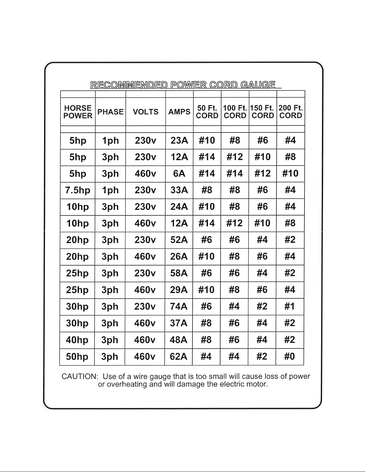
Failure to comply with the preceding warnings could result in serious bodily injury!
: disconnect power cord prior to changing the blade or performing maintenance.
: never operate the saw if there is a fuel leak.
: operate the saw only in well ventilated areas. Engine exhaust contains carbon monoxide which can
: observe all safety regulations for the safe handling of fuel. Store fuel in appropriate safety containers.
Concrete cutting as all construction work is inherently dangerous!
Page 4

NOTES
____________________________________________________
____________________________________________________
____________________________________________________
____________________________________________________
____________________________________________________
____________________________________________________
____________________________________________________
____________________________________________________
____________________________________________________
____________________________________________________
____________________________________________________
____________________________________________________
____________________________________________________
____________________________________________________
____________________________________________________
____________________________________________________
____________________________________________________
____________________________________________________
____________________________________________________
____________________________________________________
____________________________________________________
____________________________________________________
____________________________________________________
____________________________________________________
____________________________________________________
____________________________________________________
____________________________________________________
____________________________________________________
____________________________________________________
Page 5

Table of Contents
Description Page No.
Common Parts….…………………………………………………..…….....6
Front Axle Assembly........……………………………………………….....8
Screw Feed Assembly........……………………………………………..…..9
Motor Assembly, 5HP, 230V, 1 Phase.…………………………………....10
Motor Assembly, 5HP, 230V, 3 Phase.…..……………………………..…12
Motor Assembly, 5HP, 460V, 3 Phase………………..…..……………....14
Motor Assembly, 10HP, 230V, 3 Phase...…………………………...…....16
Motor Assembly, 10HP, 460V, 3 Phase ..................................................... 18
Motor Assembly, 10HP, 575V, 3 Phase ..................................................... 20
Starter Box Assembly, 3 Phase, 220-240V ................................................. 22
Starter Box Assembly, 3 Phase, 415-480V ................................................. 23
Starter Box Assembly, 3 Phase, 550-600V ................................................. 25
Starter Box, 220-240V ................................................................................ 26
Starter Box, 415-480V ................................................................................ 28
Starter Box, 550-600V ................................................................................ 30
Blade Shaft Assembly ................................................................................. 32
Blade Shaft Assembly (10HP, 230/460V Units) ........................................ 33
Blade Shaft Assembly (10HP, 575V Units) ............................................... 34
14” Blade Guard Assembly ........................................................................ 35
18” Blade Guard Assembly ........................................................................ 36
20” Blade Guard Assembly ........................................................................ 37
Pointer Assembly ........................................................................................ 38
Pointer Assembly (10HP Units).................................................................. 39
Warranty………………..……………………..……………………..…Rear Cover
Page 6
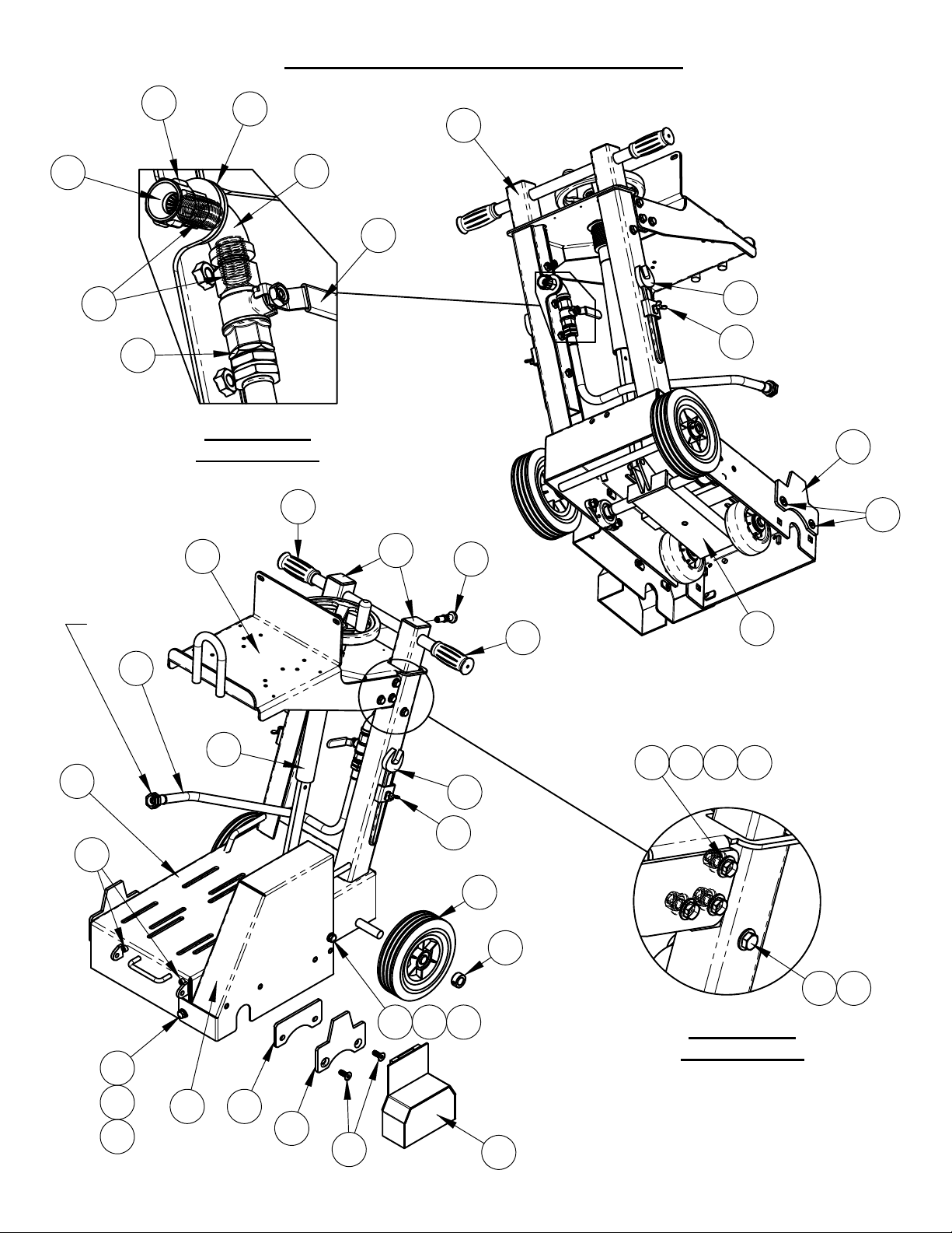
6090147 CC1300 XL COMMON PARTS
6
23
19
17
22
DETAIL B
SCALE 1 : 3
25
21
30
20
18
29
28
13
14
10
9
24
TO BLADE
GUARD
16
1
15
5
33
30
4 27 26
4
13
14
3
624
8
DETAIL A
32
31 4
SCALE 1 : 4
6
4
7
11
10
9
12
Page 7

CC1300XL COMMON PARTS - 6090147 (Regular Cut)
7
- 6048877 (Upcut)
ITEM PART NO.
1 6048181 1 Frame Weldment (Regular Cut)
6048269 1 Frame Weldment (Upcut)
2 2501439 2 Wheel, 8 x 2 x 3/4"
3 2400615 2 Set Collar, 3/4"
4 2900014 16 Flat Washer, 3/8" SAE
5 2900314 1 Cap Screw, Hex Hd., M10-1.5 x 20mm
6 2900321 2 Lock Washer, M10 Split
7 6048001 1 Belt Guard (Regular Cut)
6048149 1 Belt Guard (Upcut)
8 2900320 1 Cap Screw, Hex Hd., M10-1.5 x 100mm
9 2900744 4 Capscrew, Flat Hd., M10 x 25mm
10 6048908 2 Tapered Guard Mount
11 6048915 1 Tapered Guard Mount Spacer
12 6048906 1 Shaft Guard
13 2500256 2 Wrench Head
14 2900307 2 Wing Screw, M6 x 16mm
15 2900980 2 Capscrew, Soc. Hd., M8 X 10mm
16 6011055 1 Water Hose Assembly, 30" Long
17 3200155 1 Fitting, 1/2" M. Pipe to 3/4" M. Garden
18 3200027 1 Water Valve
19 3200008 2 Close Nipple, 1/2" NPT
20 3200209 1 Pipe Elbow, 1/2" Female
21 2900425 1 Flat Washer, 7/8" SAE
22 3200022 1 Fitting, 1/2" F. Pipe to 3/4" F. Garden
23 3200025 1 Hose Filter Washer
24 2400138 1 Indexing Plunger 1/2-13
25 6030318 1 Lift Bar Assembly
26 2900018 6 Lock Nut, 3/8-16 Nylon
27 2900005 6 Cap Screw, Hex Hd., 3/8-16 x 1"
28 6040213 1 Sliding Handle Weldment
29 2501441 2 Cap, 2" Sq. Tube
30 2500636 2 Handle Grip
31 2900596 2 Cap Screw, Hex Hd., 3/8-16 x 2-1/2"
32 6048184 1 Front Axle Assembly
33 6048183 1 Screw Feed Assembly
Default
/QTY.
DESCRIPTION
Page 8
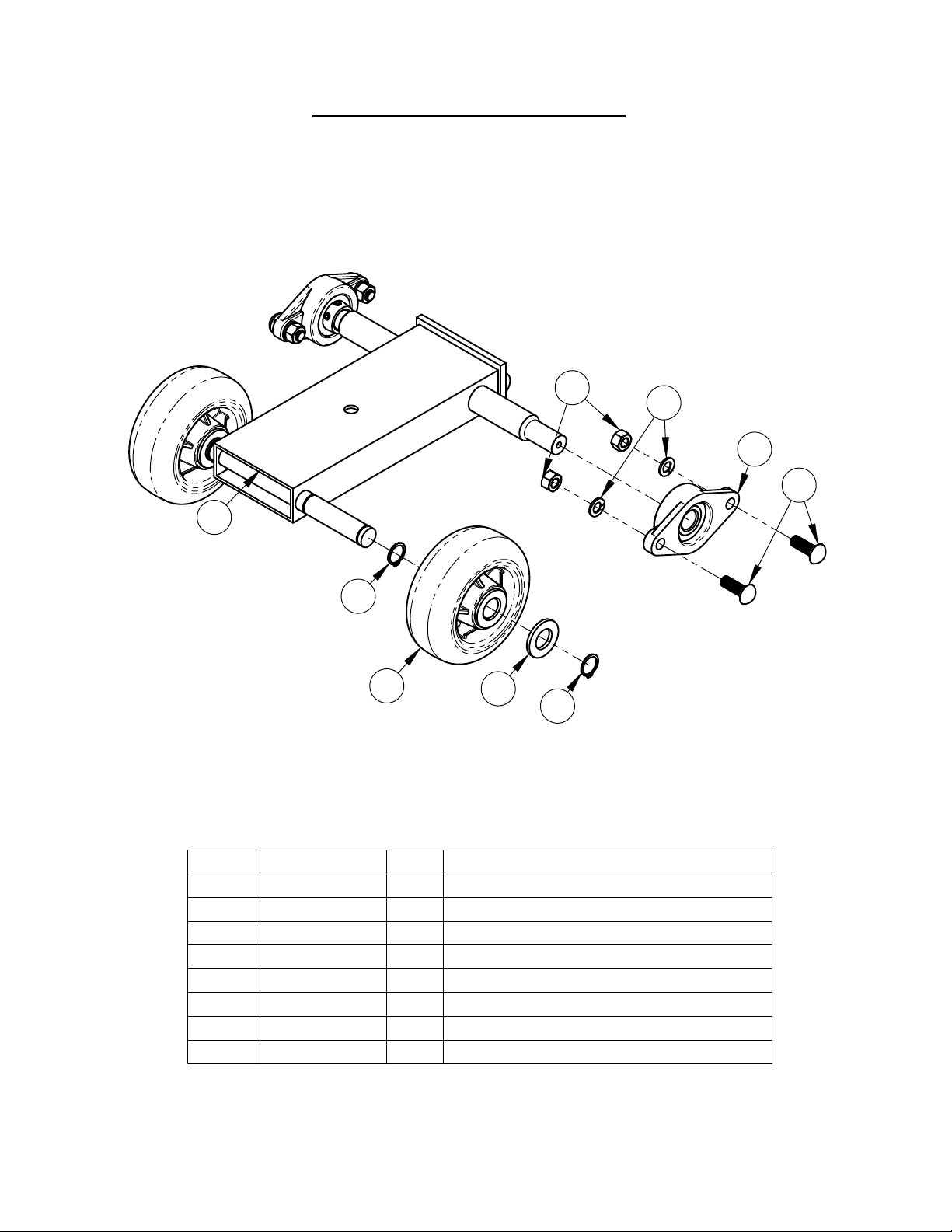
6048184 Front Axle Assembly
8
8
1
2
3
4
2
7
5
6
ITEM PART NO. QTY. DESCRIPTION
1 6040212 1 Front Axle Weldment
2 2501186 4 Retaining Ring, External 3/4"
3 2500005 2 Wheel, 5" x 2" x 3/4"
4 2900003 2 Flat Washer, 3/4" SAE
5 2500011 2 Flg Mnt Brg 3/4" Peer UCFT204-12-90
6 2900324 4 Carriage Bolt, M10-1.75 x 30
7 2900321 4 Lock Washer, M10 Split
8 2900304 4 Lock Nut, M10-1.5 Nylon Insert
Page 9
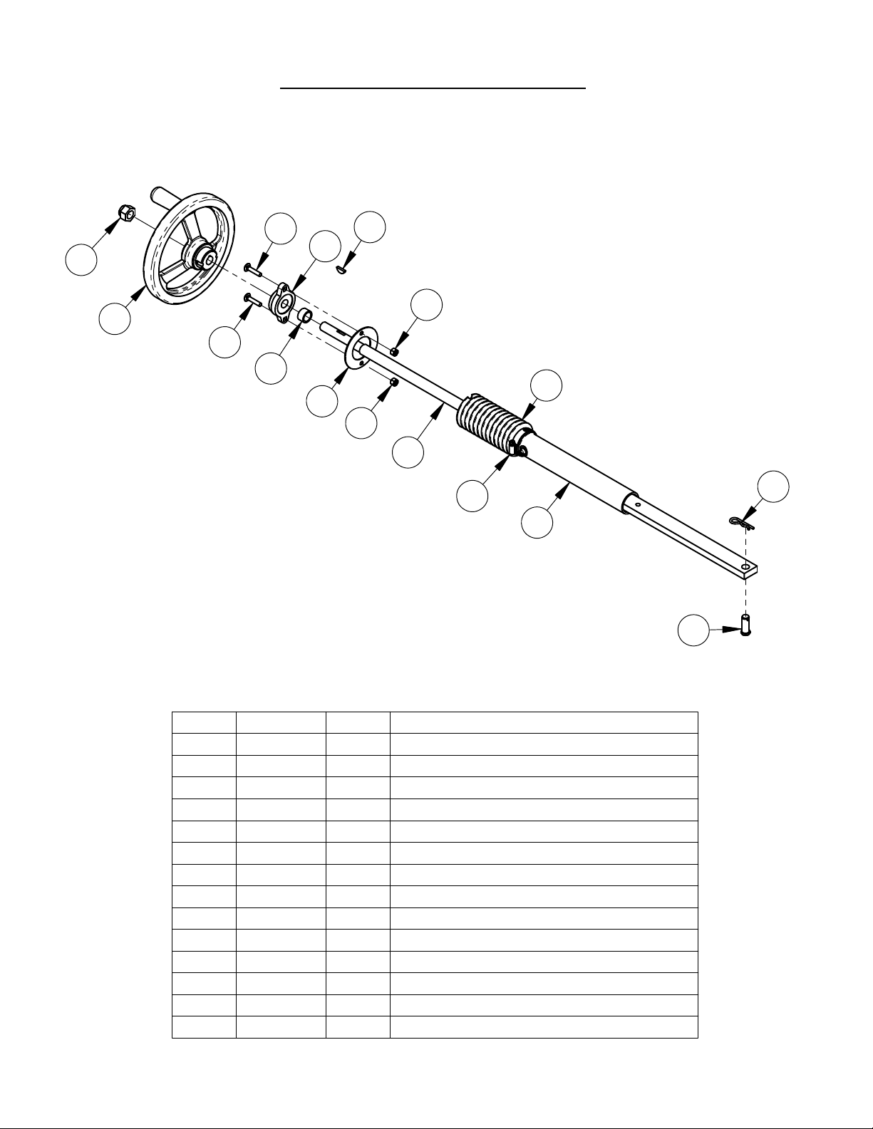
Screw Feed Assembly #6048183
9
11
7
11
12
5
14
1
2
3
10
4
8
9
10
6
13
ITEM PART NO. QTY DESCRIPTION
1 6047928 1 Adjustment Shaft W/Grease Fitting
2 2900266 1 Clevis Pin, 1/2 x 1-1/4"
3 2900276 1 Hairpin Cotter, 1/8" x 1/2" to 3/4"
4 2500807 1 Bearing, 5/8", Two Bolt Flange
5 6047929 1 Adjustment Screw
6 6047931 1 Spacer Tube 7/8 x 1/2
7 2900352 1 Woodruff Key, 5/32 x 3/4, #506
8 2900355 1 Lock Nut, 5/8-18, Flex Top
9 2500800 1 Handwheel, 8" x 5/8"
10 2900373 2 Carriage Bolt, 1/4-20 x 1-1/4", GR5
11 2900010 2 Lock Nut, 1/4-20 Nylon
12 6048036 1 Bellow, 5-1/2"
13 6048038 1 Bellow Mount Washer
14 3202142 1 Hose Clamp #24
Page 10
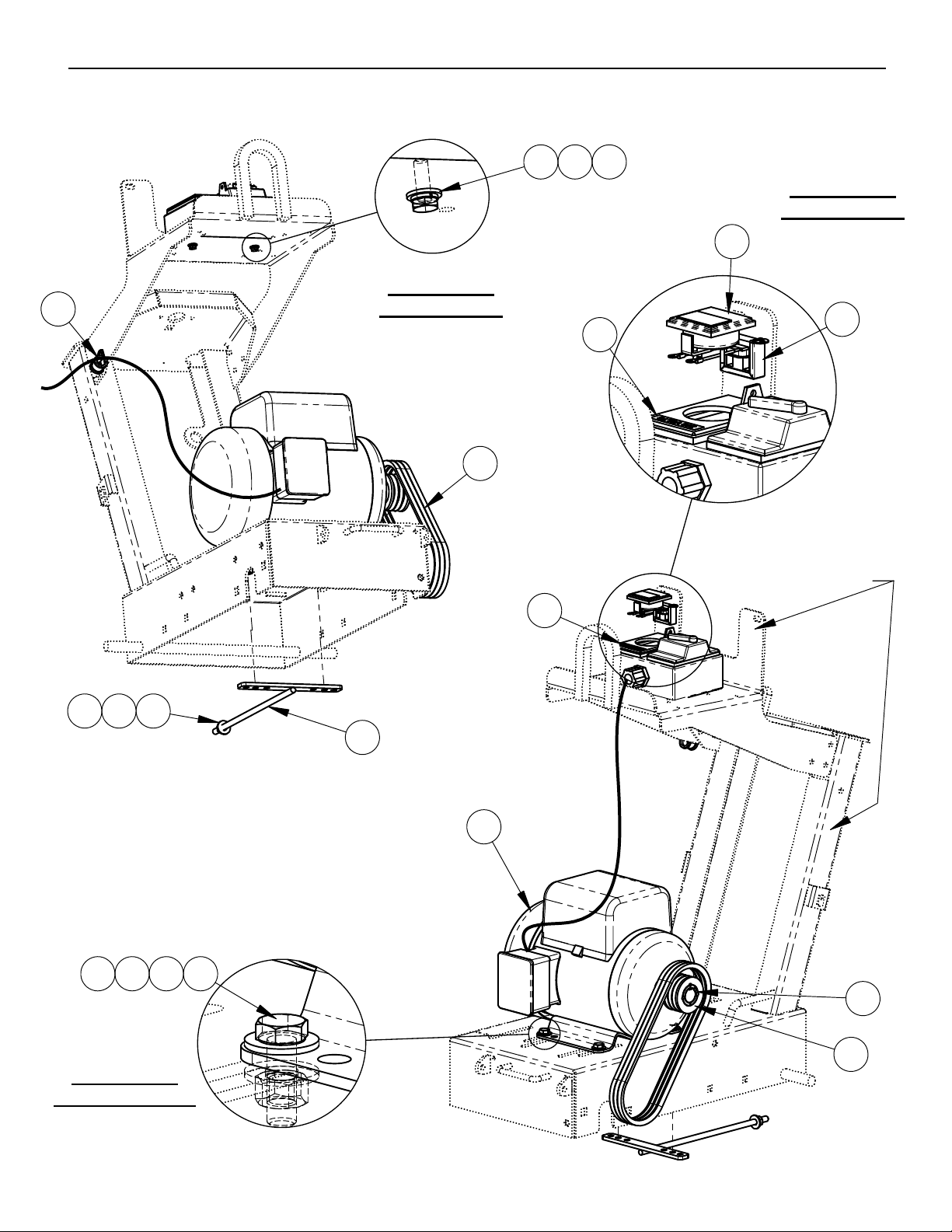
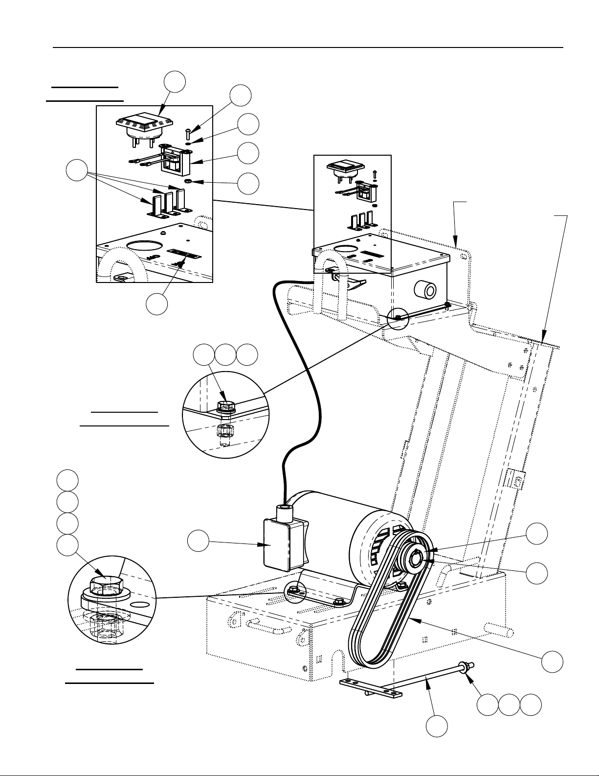
6041347 CC1300 XL ELECTRIC MOTOR OPTION, 5HP, 230V, 1-PHASE
10
11
DETAIL B
SCALE 1 : 2
10
2X
16
15 17
14
DETAIL C
SCALE 1 : 4
12
13
SHOWN FOR
REFERENCE
4 35
3
4X
3
DETAIL A
SCALE 1 : 1.5
14
2
1
67
9
8
Page 11

6041347 CC1300 XL ELECTRIC MOTOR OPTION, 5HP, 230V, 1-PHASE
11
ITEM PART NO. QTY. DESCRIPTION
1 2600278 1 Motor, 5HP, 230V, 1 Ph
2 6040261 1 Belt Adjustment Weldment
3 2900473 9 Flat Washer, 3/8" USS
4 2900321 1 Lock Washer, M10 Split
5 2900325 1 Hex Nut, M10-1.5
6 2900223 4 Cap Screw, Hex Hd., M10-1.5 x 30mm
7 2900304 4 Lock Nut, M10-1.5 Nylon Insert
8 2500022 1 Sheave, 2.65 - 3 Groove
9 2500027 1 Taper Bushing, 1-1/8" W/ Setscrews & Key
10 2500380 3 V-Belt, 3VX300
11 2801151 1 Hose Clamp, 3/4" x 3/4" Wide
12 2800253 1 Ampmeter, 0-40 Amp, AC
13 2800085 1 AC Current Transformer
14 1800810 1 Voltage Label, 230V
15 2900009 2 Flat Washer, 1/4" SAE
16 2900024 2 Lock Washer, 1/4" Split
17 2900144 2 Cap Screw, Hex Hd., 1/4-20 x 3/4"
18 6048181 1 Frame Weldment (Regular Cut)
19 6030318 1 Lift Bar Assembly
WITH UPCUT FRAME,6048269, REVERSE MOTOR MOUNTING.
Page 12
6043436 CC1300XL ELECTRIC MOTOR OPTION, 5HP, 230V, 3-PHASE
12
DETAIL B
SCALE 1 : 4
16
17
11
4X
13
14
12
15
18
19 20
SHOWN FOR
REFERENCE
DETAIL C
SCALE 1 : 1.5
4X
7
3
3
6
DETAIL A
SCALE 1 : 1.5
1
8
9
10
53
4
2
Page 13

6043436 CC1300XL ELECTRIC MOTOR OPTION, 5HP, 230V, 3-PHASE
13
ITEM PART NO. QTY. DESCRIPTION
1 2600296 1 CC1300xl 5HP Motor & Starter Box
2 6040261 1 Belt Adjustment Weldment
3 2900473 9 Flat Washer, 3/8" USS
4 2900321 1 Lock Washer, M10 Split
5 2900325 1 Hex Nut, M10-1.5
6 2900223 4 Cap Screw, Hex Hd., M10-1.5 x 30mm
7 2900304 4 Lock Nut, M10-1.5 Nylon Insert
8 2500022 1 Sheave, 2.65 - 3 Groove
9 2500027 1 Taper Bushing, 1-1/8" W/ Setscrews & Key
10 2500380 3 V-Belt, 3VX300
11 2800253 1 Amp Meter, 0-40 AC
12 2800085 1 Transformer, 115V
13 2900090 2 Machine Screw, Rd. Hd., #6-32 x 1/2"
14 2900092 2 Lock Washer, #6 Split
15 2900091 2 Hex Nut, #6-32
16 2800551 3 Heater, 12.1-12.7 Amp
17 1800810 1 Voltage Label, 230V
18 2900926 4 Flat Washer, M5
19 2900309 4 Cap Screw, Hex Hd., M5-0.8 x 20mm
20 2900301 4 Lock Nut, M5-0.8 Nylon Insert
21 6048181 1 Frame Weldment (Regular Cut)
22 6030318 1 Lift Bar Assembly
Page 14

6043437 CC1300XL ELECTRIC MOTOR OPTION, 5HP, 460V, 3-PHASE
14
DETAIL B
SCALE 1 : 4
16
17
11
4X
13
14
18
19 20
12
15
SHOWN FOR
REFERENCE
DETAIL C
SCALE 1 : 1.5
4X
7
3
3
6
DETAIL A
SCALE 1 : 1.5
1
8
9
10
4
35
2
Page 15

6043437 CC1300XL ELECTRIC MOTOR OPTION, 5HP, 460V, 3-PHASE
15
ITEM PART NO. QTY. DESCRIPTION
1 2600512 1 CC1300xl 5HP Motor & Starter Box
2 6040261 1 Belt Adjustment Weldment
3 2900473 9 Flat Washer, 3/8" USS
4 2900321 1 Lock Washer, M10 Split
5 2900325 1 Hex Nut, M10-1.5
6 2900223 4 Cap Screw, Hex Hd., M10-1.5 x 30mm
7 2900304 4 Lock Nut, M10-1.5 Nylon Insert
8 2500022 1 Sheave, 2.65 - 3 Groove
9 2500027 1 Taper Bushing, 1-1/8" W/ Setscrews & Key
10 2500380 3 V-Belt, 3VX300
11 2800253 1 Amp Meter, 0-40 AC
12 2800085 1 Transformer, 115V
13 2900090 2 Machine Screw, Rd. Hd., #6-32 x 1/2"
14 2900092 2 Lock Washer, #6 Split
15 2900091 2 Hex Nut, #6-32
16 2800536 3 Heater, 6.3 - 6.9 Amp
17 1800811 1 Voltage Label, 460V
18 2900926 4 Flat Washer, M5
19 2900309 4 Cap Screw, Hex Hd., M5-0.8 x 20mm
20 2900301 4 Lock Nut, M5-0.8 Nylon Insert
21 6048181 1 Frame Weldment (Regular Cut)
22 6030318 1 Lift Bar Assembly
Page 16

6043400 CC1300 XL ELECTRIC MOTOR OPTION, 10HP, 230V, 3-PHASE
16
4X
18
17 19
DETAIL B
SCALE 1 : 2
16
13
SHOWN FOR
REFERENCE
12
11
45 3
DETAIL A
SCALE 1 : 2
2
1
36
374X
10
8
11
13
9
Page 17

6043400 CC1300 XL ELECTRIC MOTOR OPTION, 10HP, 230V, 3-PHASE
17
ITEM
NO.
1 2600187 1 Motor, 10hp 3 Phase Baldor
2 6040261 1 Belt Adjustment Weldment
3 2900473 9 Flat Washer, 3/8" USS
4 2900321 1 Lock Washer, M10 Split
5 2900325 1 Hex Nut, M10-1.5
6 2900223 4 Cap Screw, Hex Hd., M10-1.5 x 30mm
7 2900304 4 Lock Nut, M10-1.5 Nylon Insert
8 6048046 1 Key, 5/16" Sq. x 1-1/2"
9 6048897 1 Sheave, 2.65 - 4 Groove
10 2900036 1 Set Screw, Soc. Hd., 5/16-18 x 1/4"
11 6048319 1 Blade Guard Spacer
12 2900908 3 Cap Screw, Flat Hd., M10-1.5 x 80mm
13 2500380 4 V-Belt, 3VX300
14 6048181 1 Frame Weldment (Regular Cut)
15 6030318 1 Lift Bar Assembly
PART
NUMBER
QTY. DESCRIPTION
16 6004894 1 Starter Box Assembly, 3-Phase, 220-240V
17 2900311 4 Cap Screw, Hex Hd., M6-1.0 x 25mm
18 2900765 4 Lock Washer, M6 Split
19 2901359 4 Fender Washer, M6
Page 18

6043430 CC1300 XL ELECTRIC MOTOR OPTION, 10HP, 460V, 3-PHASE
18
4X
17
16 18
DETAIL B
SCALE 1 : 2
13
12
11
4
53
19
SHOWN FOR
REFERENCE
2
1
36
374X
10
DETAIL A
SCALE 1 : 2
8
11
9
13
Page 19

6043430 CC1300 XL ELECTRIC MOTOR OPTION, 10HP, 460V, 3-PHASE
19
ITEM
NO.
1 2600187 1 Motor, 10hp 3 Phase Baldor
2 6040261 1 Belt Adjustment Weldment
3 2900473 9 Flat Washer, 3/8" USS
4 2900321 1 Lock Washer, M10 Split
5 2900325 1 Hex Nut, M10-1.5
6 2900223 4 Cap Screw, Hex Hd., M10-1.5 x 30mm
7 2900304 4 Lock Nut, M10-1.5 Nylon Insert
8 6048046 1 Key, 5/16" Sq. x 1-1/2"
9 6048897 1 Sheave, 2.65 - 4 Groove
10 2900036 1 Set Screw, Soc. Hd., 5/16-18 x 1/4"
11 6048319 1 Blade Guard Spacer
12 2900908 3 Cap Screw, Flat Hd., M10-1.5 x 80mm
13 2500380 4 V-Belt, 3VX300
14 6048181 1 Frame Weldment (Regular Cut)
15 6030318 1 Lift Bar Assembly
PART
NUMBER
QTY. DESCRIPTION
16 2900311 4 Cap Screw, Hex Hd., M6-1.0 x 25mm
17 2900765 4 Lock Washer, M6 Split
18 2901359 4 Fender Washer, M6
19 6004898 1 Starter Box Assembly, 3-Phase, 415-480V
Page 20

6043432 CC1300 XL ELECTRIC MOTOR OPTION, 10HP, 575V, 3-PHASE
20
4X
18
17 19
DETAIL B
SCALE 1 : 2
16
13
SHOWN FOR
REFERENCE
12
11
4
35
DETAIL A
SCALE 1 : 2
2
36
374X
11
1
10
8
9
13
Page 21

6043432 CC1300 XL ELECTRIC MOTOR OPTION, 10HP, 575V, 3-PHASE
21
ITEM
NO.
1 2600703 1 Motor, 10 HP, 575V, 3 PH. Baldor
2 6040261 1 Belt Adjustment Weldment
3 2900473 9 Flat Washer, 3/8" USS
4 2900321 1 Lock Washer, M10 Split
5 2900325 1 Hex Nut, M10-1.5
6 2900223 4 Cap Screw, Hex Hd., M10-1.5 x 30mm
7 2900304 4 Lock Nut, M10-1.5 Nylon Insert
8 6048046 1 Key, 5/16" Sq. x 1-1/2"
9 6048897 1 Sheave, 2.65 - 4 Groove
10 2900036 1 Set Screw, Soc. Hd., 5/16-18 x 1/4"
11 6047308 1 Blade Guard Spacer, 3"
12 2901507 3 Cap Screw, Flat Hd., M10-1.5 x 100mm
13 2500380 4 V-Belt, 3VX300
14 6048181 1 Frame Weldment (Regular Cut)
15 6030318 1 Lift Bar Assembly
PART
NUMBER
QTY. DESCRIPTION
16 6004901 1 Starter Box Assembly, 3-Phase, 550-600V
17 2900311 4 Cap Screw, Hex Hd., M6-1.0 x 25mm
18 2900765 4 Lock Washer, M6 Split
19 2901359 4 Fender Washer, M6
Page 22

STARTER BOX ASSEMBLY, 3-PHASE, 220-240V
22
TO STARTER
BOX
OVERLOAD
??
#6004894
2
4
11
10
12
5
7
3
6
8
1
9
TO MOTOR
FOR CUSTOMER
SUPPLIED
POWER CORD
ITEM PART NO. QTY. DESCRIPTION
1 2804008 1 Starter Box, 220-240V
2 2800253 1 Amp Meter w/ Bracket, 0-40 AC
3 2800085 1 AC Current Transformer
4 2900090 2 Machine Screw, Rd. Hd., #6-32 x 1/2"
5 2900092 2 Lock Washer, #6 Split
6 2900091 2 Hex Nut, #6-32
7 1800810 1 Voltage Label, 230V
8 2802052 1 Cord Connector, 3/4" Thd., .63-75" Cord, 90 Deg.
9 2801304 1 Lock Nut, 3/4"
10 2800695 1 Cord Grip, 5/8-3/4", 90 Deg.
11 2800193 1 Lock Nut, 1"
12 6040423 1 Cable Assy., 10 Ga., 4 Wire x 54"
Page 23

STARTER BOX ASSEMBLY, 3-PHASE, 415-480V
23
TO STARTER
BOX
OVERLOAD
#6004898
2
4
7
5
3
6
11
TO
MOTOR
ITEM PART NO. QTY. DESCRIPTION
10 2800695 1 Cord Grip, 5/8-3/4", 90 Deg.
11 2800193 1 Lock Nut, 1"
12 6040423 1 Cable Assy., 10 Ga., 4 Wire x 54"
8
9
12
10
1
FOR CUSTOMER
SUPPLIED
POWER CORD
1 2804007 1 Starter Box, 415-480V
2 2800252 1 Amp Meter, 0-20 AC
3 2800085 1 AC Current Transformer
4 2900090 2 Machine Screw, Rd. Hd., #6-32 x 1/2"
5 2900092 2 Lock Washer, #6 Split
6 2900091 2 Hex Nut, #6-32
7 1800811 1 Voltage Label, 460V
8 2802052 1 Cord Connector, 3/4" Thd., .63-75" Cord, 90 Deg.
9 2801304 1 Lock Nut, 3/4"
Page 24

24
Intentionally Blank
Page 25

TO STARTER
25
BOX
OVERLOAD
STARTERBOX ASSEMBLY, 3-PHASE, 550-600V
??
#6004901
2
4
7
5
3
TO
MOTOR
6
8
12
10
11
9
FOR CUSTOMER
SUPPLIED POWER
ITEM PART NO. QTY. DESCRIPTION
1 2802061 1 Starter Box, 550-600V
2 2800252 1 Amp Meter, 0-20 AC
3 2800085 1 AC Current Transformer
4 2900090 2 Machine Screw, Rd. Hd., #6-32 x 1/2"
5 2900092 2 Lock Washer, #6 Split
6 2900091 2 Hex Nut, #6-32
7 1800812 1 Voltage Label, 575V
8 2802052 1 Cord Connector, 3/4" Thd., .63-75" Cord, 90 Deg.
9 2801304 1 Lock Nut, 3/4"
10 2800695 1 Cord Grip, 5/8-3/4", 90 Deg.
11 2800193 1 Lock Nut, 1"
12 6040423 1 Cable Assy., 10 Ga., 4 Wire x 54"
1
CORD
Page 26

STARTER BOX, 220-240 VOLT
26
#2804008
13
16
13
6
7
14
15
14
5
8
12
11
4
10
1
2
9
5
3
Page 27

STARTER BOX, 220-240 VOLT
27
#2804008
13
SET TO
MOTOR AMP
RATING
6
TRIP CLASS - 10
RESET - A
PHASE - OFF
5
7
14
N.O. ONLY
ITEM PART NO. QTY. DESCRIPTION
1 6040300D 1 Starter Box Base
2 2901588 4 M6-1.0 Threaded Insert
3 6040598 1 Sub-plate
4 2900676 4 Machine Screw, Pan Hd., M4-0.7 x 8mm
5 2801704 1 Contactor, 220-240V (includes coil)
2801265 1 Replacement Coil, 220-240V
6 2801699 1 Overload Relay, 9-45 AMP
7 2801676 1 Auxilary Contacts, 1NO-NC
8 2901827 4 Cap Screw, Soc. Hd., #8-32 x 5/8"
9 2901437 4 Flat Washer, #10
10 2800315 2 Grounding Lug
11 2900024 1 Lock Washer, 1/4" Split
12 2901891 1 Cap Screw, Hex Hd., 1/4-28 x 1/2"
13 2801636 1 E-Stop Switch, 600V
14 2801639 1 Pushbutton, N.O., 600V
15 6048293 1 Starter Box Cover
16 2701414 4 Fastener, Electrical Box Top
Page 28

STARTER BOX, 415-480 VOLT
28
#2804007
13
13
16
6
7
14
15
14
5
10
11
8
9
5
4
1
2
12
3
Page 29

SET TO
29
MOTOR AMP
RATING
STARTER BOX, 415-480 VOLT
#2804007
15
13
6
TRIP CLASS - 10
RESET - A
PHASE - OFF
5
N.O. ONLY
7
ITEM PART NO. QTY. DESCRIPTION
1 6040300D 1 Starter Box Base
2 2901588 4 M6-1.0 Threaded Insert
3 6040598 1 Sub-plate
4 2900676 4 Machine Screw, Pan Hd., M4-0.7 x 8mm
5 2801707 1 Contactor, 415-480V (Includes Coil)
2801266 1 Replacement Coil, 415-480V
6 2801699 1 Overload Relay, 9-45 AMP
7 2801676 1 Auxilary Contacts, 1NO-NC
8 2901827 4 Cap Screw, Soc. Hd., #8-32 x 5/8"
9 2901437 4 Flat Washer, #10
10 2901891 1 Cap Screw, Hex Hd., 1/4-28 x 1/2"
11 2900009 1 Flat Washer, 1/4" SAE
12 2800315 2 Grounding Lug
13 2801636 1 E-Stop Switch, 600V
14 2801639 1 Pushbutton, N.O., 600V
15 6048293 1 Starter Box Cover
16 2701414 4 Fastener, Electrical Box Top
Page 30

STARTER BOX, 550-600 VOLT
30
#2802061
13
6
16
13
14
15
14
5
7
12
11
10
4
1
8
9
5
3
2
Page 31

SET TO
31
MOTOR AMP
RATING
STARTER BOX, 550-600 VOLT
#2802061
14
13
6
TRIP CLASS - 10
RESET - A
PHASE - OFF
5
7
ITEM PART NO. QTY. DESCRIPTION
1 6040300D 1 Starter Box Base
2 2901588 4 M6-1.0 Threaded Insert
3 6040598 1 Sub-plate
4 2900676 4 Machine Screw, Pan Hd., M4-0.7 x 8mm
5 2801709 1 Contactor, 550-600V (includes coil)
2801267 1 Replacement Coil, 550-600V
6 2801699 1 Overload Relay, 9-45 AMP
7 2801676 1 Auxilary Contacts, 1NO-NC
8 2901827 4 Cap Screw, Soc. Hd., #8-32 x 5/8"
9 2901437 4 Flat Washer, #10
10 2800315 2 Grounding Lug
11 2900024 1 Lock Washer, 1/4" Split
12 2901891 1 Cap Screw, Hex Hd., 1/4-28 x 1/2"
13 2801636 1 E-Stop Switch, 600V
14 2801639 1 Pushbutton, N.O., 600V
15 6048293 1 Starter Box Cover
16 2701414 4 Fastener, Electrical Box Top
N.O. ONLY
Page 32

13
32
12
6041041 BLADE SHAFT ASSEMBLY
6
5
15
1
4
13
15
ITEM PART NO. QTY DESCRIPTION
1 6048866 1 Blade Shaft
2 2500025 1 Sheave, 3.65-3 Groove
3 2500576 2 Flange Block Bearing, 1-1/4"
4 6048037 2 Bearing Spacer
5 6048018 2 Key, 3/16" Sq. x 3/4"
6 6010169 1 Key, 1/4" Sq. x 1-1/4"
7 2500337 1 Taper Bushing, 1-1/4"
9 6048008 2 Inner Flange 4-1/2"
10 2900065 1 Flange Nut, 5/8-11 R.H.
12 6048009 1 Outer Flange, 4-1/2" w/ Pin
13 2900066 1 Flange Nut, 5/8-11 L.H.
15 2900327 4 Lock Nut, M12-1.75 Nylon Insert
13 2900046 4 Carriage Bolt, 3/8"-16 X 1-1/4"
3
13
4
2
7
9
10
Page 33

11
33
6040500 BLADE SHAFT ASSEMBLY, 10 HP, 230/460 VOLT
5
4
10
8
2
1
ALSO FIT 575 VOLT MODELS
PRIOR TO MARCH 2011.
ITEM PART NO. QTY. DESCRIPTION
1 6048865 1 Blade Shaft
2 2500576 2 Flange Block Bearing, 1-1/4"
3 6048037 2 Bearing Spacer
4 6048018 2 Key, 3/16" Sq. x 3/4"
5 6048134 1 Key, 1/4" Sq. x 2-1/4"
6 2500621 1 Sheave, 3V-3.65-4 Groove (1610)
7 2500337 1 Taper Bushing, 1-1/4"
8 6048008 2 Inner Flange 4-1/2"
9 2900065 1 Flange Nut, 5/8-11 R.H.
10 6048009 1 Outer Flange, 4-1/2" w/ Pin
11 2900066 1 Flange Nut, 5/8-11, L. Hand
12 2900322 4 M12-1.75 x 35 Carriage Bolt
13 2900327 4 Lock Nut, M12-1.75 Nylon Insert
13
2
3
12
6 9
7 8
Page 34

11
34
6040528 BLADE SHAFT ASSEMBLY, 10HP, 575V UNITS.
5
4
10
8
2
ITEM PART NO. QTY. DESCRIPTION
1 6048880 1 Blade Shaft
2 2500576 2 Flange Block Bearing, 1-1/4"
3 6048037 2 Bearing Spacer
4 6048018 2 Key, 3/16" Sq. x 3/4"
5 6048134 1 Key, 1/4" Sq. x 2-1/4"
6 2500621 1 Sheave, 3V-3.65-4 Groove (1610)
7 2500337 1 Taper Bushing, 1-1/4"
8 6048008 2 Inner Flange 4-1/2"
9 2900065 1 Flange Nut, 5/8-11 R.H.
10 6048009 1 Outer Flange, 4-1/2" w/ Pin
11 2900066 1 Flange Nut, 5/8-11, L. Hand
12 2900322 4 M12-1.75 x 35 Carriage Bolt
13 2900327 4 Lock Nut, M12-1.75 Nylon Insert
1
13
2
3
12
6
7
8
9
Page 35

8
35
14" Blade Guard Assembly
#6048912
18.5
18.3
18.2
18.1
18.4
16
16
18
19
14
7
5
6
16
3
2
1
14
13
11
12
15
17
9
4
5
9
10
ITEM PART NO. QTY. DESCRIPTION
1 6048911 1 14" Blade Guard
2 2500829 1 Water Manifold Gasket
3 6048123 1 Water Manifold
4 6048283 2 Water Tube for 14" Guard
5 3200001 3 Plug, 1/8" NPT
6 3200002 1 Fitting, 3/8" M. Pipe to 3/4" M. Garden
7 2900009 2 Flat Washer, 1/4" SAE
8 2900244 2 Cap Screw, Hex Hd., M6 x 45mm
9 2900302 6 Lock Nut, M6 Nylon
10 6048155 2 Water Tube Clamp
11 2900308 4 Cap Screw, Flat Hd. Soc., M6 x 16mm
12 6048039 1 Splash Flap
13 2900016 2 Flat Washer, #10 USS
14 2900309 4 Cap Screw, Hex Hd., M5 x 20mm
15 2900083 2 Fender Washer, 1/4" I.D. x 1-1/4" O.D.
16 2900301 6 Lock Nut, M5 Nylon
17 2500066 1 Spring, 3/8 X .055 X 3"
18 6048026 1 Hinge Assy., Metric Fasteners
18.1 2500270 1 Blade Guard Hinge
18.2 2900009 6 Flat Washer, 1/4" SAE
18.3 2900310 5 Cap Screw, Hex Hd., M6 x 20mm
18.4 2900302 7 Lock Nut, M6 Nylon
18.5 2900312 1 Cap Screw, Hex Hd., M6 x 35mm
19 1800001 1 Warning Label
Page 36

18" Blade Guard Assembly
36
6048910
8
7
5
6
3
18.2
18.4
18.3
18.1
16
19
15
14
10
2
4
16
5
1
14
13
12
17
5
10
9
11
ITEM PART NO. QTY. DESCRIPTION
1 6048909 1 18" Blade Guard Assembly
2 2500829 1 Water Manifold Gasket
3 6048123 1 Water Manifold
4 6048243 2 Water Tube for 18" Guard
5 3200001 3 Plug, 1/8" NPT
6 3200002 1 Fitting, 3/8" M. Pipe to 3/4" M. Garden
7 2900009 2 Flat Washer, 1/4" SAE
8 2900244 2 Cap Screw, Hex Hd., M6-1.0 x 45mm
9 6048155 2 Water Tube Clamp
10 2900302 6 Lock Nut, M6 Nylon
11 2900308 4 Cap Screw, Flat Hd., M6-1.0 x 16mm
12 6048039 1 Splash Flap
13 2900016 2 Flat Washer, #10 USS
14 2900309 4 Cap Screw, Hex Hd., M5-0.8 x 20mm
15 2500067 1 Spring, 3/8" x 4"
16 2900301 6 Lock Nut, M5-0.8 Nylon Insert
17 2900083 2 Fender Washer, 1/4" x 1-1/4"
18 6048027 1 Hinge Assy., Metric Fasteners
18.1 2500270 1 Blade Guard Hinge
18.2 2900009 6 Flat Washer, 1/4" SAE
18.3 2900310 6 Cap Screw, Hex Hd., M6 x 20mm
18.4 2900302 6 Lock Nut, M6 Nylon
19 1800001 1 Warning Label
Page 37

20" Blade Guard Assembly
37
#6048904
8
7
5
6
3
2
18.1
18.2
18.3
18.2
18.4
16
16
14
18
19
17
9
5
109
11
16
4
5
1
14
13
12
15
ITEM PART NO. QTY. DESCRIPTION
1 6048905 1 20" Blade Guard
2 2500829 1 Water Manifold Gasket
3 6048123 1 Water Manifold
4 6010085 2 Water Tube for 20" Guard
5 3200001 3 Plug, 1/8" NPT
6 3200002 1 Fitting, 3/8" M. Pipe to 3/4" M. Garden
7 2900009 2 Flat Washer, 1/4" SAE
8 2900244 2 Cap Screw, Hex Hd., M6 x 45mm
9 2900302 6 Lock Nut, M6 Nylon
10 6048155 2 Water Tube Clamp
11 2900308 4 Cap Screw, Flat Hd. Soc., M6 x 16mm
12 6048039 1 Splash Flap
13 2900016 2 Flat Washer, #10 USS
14 2900309 4 Cap Screw, Hex Hd., M5 x 20mm
15 2900083 2 Fender Washer, 1/4" x 1-1/4"
16 2900301 6 Lock Nut, M5 Nylon
17 2500067 1 Spring, 3/8" x 4"
18 6048027 1 Hinge Assy., Metric Fasteners
18.1 2500270 1 Blade Guard Hinge
18.2 2900009 6 Flat Washer, 1/4" SAE
18.3 2900310 6 Cap Screw, Hex Hd., M6 x 20mm
18.4 2900302 6 Lock Nut, M6 Nylon
19 1800001 1 Warning Label
Page 38

6048080 POINTER ASSEMBLY
38
11
7
6
5
1
3
4
10
2
8
ITEM NO.
PART
NUMBER
Default/
QTY.
DESCRIPTION
1 6048069 1 Pointer Bar - Straight
2 6048070 1 Pointer Bar - Offset
3 2500624 1 Wheel, 3"
4 2900018 1 Lock Nut, 3/8-16 Nylon
5 2900006 1 Lock Washer, 3/8" Split
6 2900033 1 Hex Nut, 3/8-16
7 2900032 1 Pointer Rod
8 2900304 2 Lock Nut, M10-1.5 Nylon Insert
9 2900333 2 Cap Screw, Hex Hd., M10-1.5 x 25mm
10 6048078 1 Rope, 1/4 x 78"
11 3200221 3 Pinch Clamp, Two Ear
9
Page 39

6047994 POINTER ASSEMBLY, 10 HP UNITS
39
3
4
11
7
6
5
10
1
2
9
ITEM PART NO.
1 6048069 1 Pointer Bar - Straight
2 6048070 1 Pointer Bar - Offset
3 2500624 1 Wheel, 3"
4 2900018 1 Lock Nut, 3/8-16 Nylon
5 2900321 1 Lock Washer, M10 Split
6 2900033 1 Hex Nut, 3/8-16
7 2900743 1 Pointer Rod, 11"
8 2900304 2 Lock Nut, M10-1.5 Nylon Insert
9 2900333 2 Cap Screw, Hex Hd., M10-1.5 x 25mm
10 6048078 1 Rope, 1/4 x 78"
11 3200221 3 Pinch Clamp, Two Ear
Default/Q
TY.
8
DESCRIPTION
9
Page 40

EQUIPMENT AND PARTS
WARRANTY
Diamond Products warrants all equipment manufactured by it against defects
in workmanship or materials for a period of one (1) year from the date of
shipment to Customer.
The responsibility of Diamond Products under this Warranty is limited to
replacement or repair of defective parts at Diamond Products’ Elyria, Ohio
factory, or at a point designated by it, of such parts as shall appear to us upon
inspection at such parts, to have been defective in material or workmanship,
with expense for transportation and labor borne by Customer.
In no event shall Diamond Products be liable for consequential or
incidental damages arising out of the failure of any Product to operate properly.
Integral units such as engines, electric motors, batteries, transmissions,
etc., are excluded from this Warranty and are subject to the prime
manufacturer’s warranty.
THIS WARRANTY IS IN LIEU OF ALL OTHER WARRANTIES, EXPRESSED
OR IMPLIED, AND ALL SUCH OTHER WARRANTIES ARE HEREBY
DISCLAIMED.
333 Prospect Street, Elyria, Ohio 44035
(440) 323-4616 • (800) 321-5336 • Fax (440) 323-8689
www.diamondproducts.com
Printed in U.S.A. #1801809
 Loading...