

Page 1

DIAMOND
PRODUCTS
HYDRAULIC POWER UNIT
PARTS LIST &
OPERATOR’S MANUAL
CB35BV-XL
JULY 2012
PART#: 1801368
Page 2

Proposition 65
State of California
Warning !
Engine exhaust and some its constituents are known to the State
of California to cause cancer, birth defects, and/or other
reproductive harm.
Notification of Spark Arrester Requirement for
State of California
It is a violation of Section 4442 or 4443 to use or operate the
engine on any forest-covered, brush-covered, or grass-covered land
unless the engine is equipped with a spark arrester, as defined in
Section 4442, maintained in effective working order or the engine
is constructed, equipped, and maintained for the prevention of fire
pursuant to Section 4443.
Page 3

Table of Contents
Description Page No.
1. CB35BV-XL Hydraulic Power Supply ...................................................4
2. Hydraulic Schematic ............................................................................10
3. Hose Kit .................................................................................................11
4. Electrical Schematic .............................................................................12
5. Gas Tank Assembly ..............................................................................13
6. Hydraulic Tank Assembly .....................................................................14
7. Control Panel Assembly ......................................................................16
8. Air to Cooler Option ..............................................................................18
9. Component Locations ...........................................................................20
10. Safety Precautions ...............................................................................21
11. Descriptions and Specifications .........................................................23
12. Operating Instructions ........................................................................24
13. Operating Driven Equipment ...............................................................25
14. Maintenance Instructions ....................................................................26
15. Troubleshooting ...................................................................................26
16. Flow & Pressure Ratings, CB Power Packs……………………………27
17. Warranty Page……………………………………………………Rear Cover
Page 4
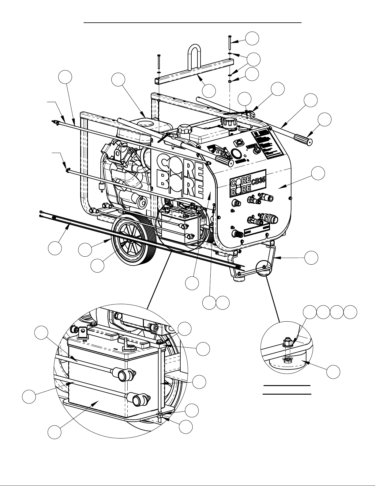
4646200 CB35XL HYDRAULIC POWER SUPPLY
4
48
5
TO
VACUUM
LINE
TO GAS
FILTER
51
50
46
7
45
43
44
27
1
8
47
49
2
4
DETAIL A
SCALE 1 : 4
52
53
38
33
41
42
4X
33
39
40
25 24
DETAIL A1
SCALE 1 : 3
6
5
57
3
Page 5

ITEM
5
1 4646156 1 CB-XL Frame Assembly
2 2400643 2 Wheel, 12 x 2-5/8 x 3/4"
3 2501767 2 Rubber Bumper
4 2400615 2 Set Collar, 3/4"
5 2900022 26 Flat Washer, 5/16" SAE
6 2900508 2 Cap Screw, Hex Hd., 5/16-18 x 1-1/2"
7 2900039 12 Lock Nut, 5/16-18 Nylon
8 4640122 1 Vanguard 35HP W/ Elec. Connector
9 3201269 1 Adapter, M14x1.5 M. to 1/4" F. Pipe
10 3200060 1 Hex Nipple, 1/4" NPT
11 3201882 1 1/4 NPT Hex Cap
12 2501434 2 Hose Clamp, 5/8" x 3/4" Wide
13 2900494 4 Cap Screw, Hex Hd., 5/16-18 x 2"
14 4646010 1 Pump Mount, SAE 2 Bolt
15 2900006 6 Lock Washer, 3/8" Split
16 2900724 4 Cap Screw, Soc. Hd., 3/8-16 x 1-1/4"
17 6048134 1 Key, 1/4" Sq. x 2-1/4"
18 2400639 1 Flex Coupling, 3/4 - 1-1/8"
19 2600569 1 Pump, 1.0 CI, 2 Bolt SAE
20 2900005 2 Cap Screw, Hex Hd., 3/8-16 x 1"
21 3202079 2 5/8" O-Ring - 5/8" MJIC
22 3201881 1 1" MJIC - 3/4" MOR, 45 Deg.
23 4646011 1 Heat Shield
24 2900024 10 Lock Washer, 1/4" Split
25 2900144 8 Cap Screw, Hex Hd., 1/4-20 x 3/4"
26 4646173 1 Hydraulic Tank Assembly
27 4646207 1 Panel Assembly, CB35
28 3202318 1 Valve, Relief, 5KSI
29 3202061 1 Fitting, 5/8" MORB x 5/8" MJIC x 90 DEG
30 2900031 2 Lock Washer, 5/16" Split
31 2900726 2 Cap Screw, Hex Hd., 5/16-18 x 2-1/2"
32 4646035 1 Fuel Tank Support
33 2900009 6 Flat Washer, 1/4" SAE
34 2900008 2 Cap Screw, Hex Hd., 1/4-20 x 1"
35 4641099 1 Gas Tank Mounting Plate
36 2900138 4 Cap Screw, Hex Hd., 5/16-18 x 1"
37 4600203 1 Gas Tank Assembly, 4.4 Gallon
38 2500584 1 Battery, 12 Volt Group Size U1
39 4646122 1 BatterySupport
40 2901405 2 Cap Screw, Hex Hd., 1/4-20 x 7-1/2"
41 2900010 2 Lock Nut, 1/4-20 Nylon
4646200 CB35XL HYDRAULIC POWER SUPPLY
42 4646049 1 Side Panel
43 4646006 2 Handle
44 2500636 2 Handle Grip
45 2900257 2 Lock Pin, T Handle, 3/8"
46 2900053 4 Rivet, 3/32" Dia.
47 4646003 1 Lifting Bar
48 2900248 2 Cap Screw, Hex Hd., 5/16-18 x 3"
49 4600160 1 Hose Assy., Gas, 1/4 x 40-3/4"
50 4600168 1 Hose Assy., 1/4 - 3/16 Barb, 50.75"
51 4643022 1 Wire Assy., Emergency Off, 65-1/2"
52 4646015 1 Battery Cable Assy., Red
53 4646016 1 Battery Cable Assy., Black
54 4646209 1 Hose Kit, CB35XL
55 1800537 1 Label, HOT
56 1801716 1 Decal, EPA EVAP Standard
57 1800169 1 Serial Number Plate, US
PART
NO.
QTY. DESCRIPTION
Page 6
12
6
4646200 CB35XL HYDRAULIC POWER SUPPLY
DETAIL B
SCALE 1 : 3
2637
8
7
5
11
10
DETAIL E
SCALE 1 : 3
1
14
57
9
56
13
1
32
DETAIL D
35
SCALE 1 : 3
15
16
17
18
33
2X
24
34
21
22
2018
19
36
4X
5
5
7
DETAIL C
SCALE 1 : 3
Page 7

ITEM
7
1 4646156 1 CB-XL Frame Assembly
2 2400643 2 Wheel, 12 x 2-5/8 x 3/4"
3 2501767 2 Rubber Bumper
4 2400615 2 Set Collar, 3/4"
5 2900022 26 Flat Washer, 5/16" SAE
6 2900508 2 Cap Screw, Hex Hd., 5/16-18 x 1-1/2"
7 2900039 12 Lock Nut, 5/16-18 Nylon
8 4640122 1 Vanguard 35HP W/ Elec. Connector
9 3201269 1 Adapter, M14x1.5 M. to 1/4" F. Pipe
10 3200060 1 Hex Nipple, 1/4" NPT
11 3201882 1 1/4 NPT Hex Cap
12 2501434 2 Hose Clamp, 5/8" x 3/4" Wide
13 2900494 4 Cap Screw, Hex Hd., 5/16-18 x 2"
14 4646010 1 Pump Mount, SAE 2 Bolt
15 2900006 6 Lock Washer, 3/8" Split
16 2900724 4 Cap Screw, Soc. Hd., 3/8-16 x 1-1/4"
17 6048134 1 Key, 1/4" Sq. x 2-1/4"
18 2400639 1 Flex Coupling, 3/4 - 1-1/8"
19 2600569 1 Pump, 1.0 CI, 2 Bolt SAE
20 2900005 2 Cap Screw, Hex Hd., 3/8-16 x 1"
21 3202079 2 5/8" O-Ring - 5/8" MJIC
22 3201881 1 1" MJIC - 3/4" MOR, 45 Deg.
23 4646011 1 Heat Shield
24 2900024 10 Lock Washer, 1/4" Split
25 2900144 8 Cap Screw, Hex Hd., 1/4-20 x 3/4"
26 4646173 1 Hydraulic Tank Assembly
27 4646207 1 Panel Assembly, CB35
28 3202318 1 Valve, Relief, 5KSI
29 3202061 1 Fitting, 5/8" MORB x 5/8" MJIC x 90 DEG
30 2900031 2 Lock Washer, 5/16" Split
31 2900726 2 Cap Screw, Hex Hd., 5/16-18 x 2-1/2"
32 4646035 1 Fuel Tank Support
33 2900009 6 Flat Washer, 1/4" SAE
34 2900008 2 Cap Screw, Hex Hd., 1/4-20 x 1"
35 4641099 1 Gas Tank Mounting Plate
36 2900138 4 Cap Screw, Hex Hd., 5/16-18 x 1"
37 4600203 1 Gas Tank Assembly, 4.4 Gallon
38 2500584 1 Battery, 12 Volt Group Size U1
39 4646122 1 BatterySupport
40 2901405 2 Cap Screw, Hex Hd., 1/4-20 x 7-1/2"
41 2900010 2 Lock Nut, 1/4-20 Nylon
4646200 CB35XL HYDRAULIC POWER SUPPLY
42 4646049 1 Side Panel
43 4646006 2 Handle
44 2500636 2 Handle Grip
45 2900257 2 Lock Pin, T Handle, 3/8"
46 2900053 4 Rivet, 3/32" Dia.
47 4646003 1 Lifting Bar
48 2900248 2 Cap Screw, Hex Hd., 5/16-18 x 3"
49 4600160 1 Hose Assy., Gas, 1/4 x 40-3/4"
50 4600168 1 Hose Assy., 1/4 - 3/16 Barb, 50.75"
51 4643022 1 Wire Assy., Emergency Off, 65-1/2"
52 4646015 1 Battery Cable Assy., Red
53 4646016 1 Battery Cable Assy., Black
54 4646209 1 Hose Kit, CB35XL
55 1800537 1 Label, HOT
56 1801716 1 Decal, EPA EVAP Standard
57 1800169 1 Serial Number Plate, US
PART
NO.
QTY. DESCRIPTION
Page 8
4646200 CB35XL HYDRAULIC POWER SUPPLY
8
GAS LINE
ROUTING
MUFFLER ONLY
IS 2707351
CATALYTIC
IS 2707355
8
23
4X
2524
DETAIL F
SCALE 1 : 2
VENT LINE
ROUTING
ROUT THRU
CLAMPS
DETAIL G
SCALE 1 : 1.5
4X TO
513
ENGINE
DETAIL J
SCALE 1 : 3
21
2x
5
29
28
3130
Page 9

ITEM
9
1 4646156 1 CB-XL Frame Assembly
2 2400643 2 Wheel, 12 x 2-5/8 x 3/4"
3 2501767 2 Rubber Bumper
4 2400615 2 Set Collar, 3/4"
5 2900022 26 Flat Washer, 5/16" SAE
6 2900508 2 Cap Screw, Hex Hd., 5/16-18 x 1-1/2"
7 2900039 12 Lock Nut, 5/16-18 Nylon
8 4640122 1 Vanguard 35HP W/ Elec. Connector
9 3201269 1 Adapter, M14x1.5 M. to 1/4" F. Pipe
10 3200060 1 Hex Nipple, 1/4" NPT
11 3201882 1 1/4 NPT Hex Cap
12 2501434 2 Hose Clamp, 5/8" x 3/4" Wide
13 2900494 4 Cap Screw, Hex Hd., 5/16-18 x 2"
14 4646010 1 Pump Mount, SAE 2 Bolt
15 2900006 6 Lock Washer, 3/8" Split
16 2900724 4 Cap Screw, Soc. Hd., 3/8-16 x 1-1/4"
17 6048134 1 Key, 1/4" Sq. x 2-1/4"
18 2400639 1 Flex Coupling, 3/4 - 1-1/8"
19 2600569 1 Pump, 1.0 CI, 2 Bolt SAE
20 2900005 2 Cap Screw, Hex Hd., 3/8-16 x 1"
21 3202079 2 5/8" O-Ring - 5/8" MJIC
22 3201881 1 1" MJIC - 3/4" MOR, 45 Deg.
23 4646011 1 Heat Shield
24 2900024 10 Lock Washer, 1/4" Split
25 2900144 8 Cap Screw, Hex Hd., 1/4-20 x 3/4"
26 4646173 1 Hydraulic Tank Assembly
27 4646207 1 Panel Assembly, CB35
28 3202318 1 Valve, Relief, 5KSI
29 3202061 1 Fitting, 5/8" MORB x 5/8" MJIC x 90 DEG
30 2900031 2 Lock Washer, 5/16" Split
31 2900726 2 Cap Screw, Hex Hd., 5/16-18 x 2-1/2"
32 4646035 1 Fuel Tank Support
33 2900009 6 Flat Washer, 1/4" SAE
34 2900008 2 Cap Screw, Hex Hd., 1/4-20 x 1"
35 4641099 1 Gas Tank Mounting Plate
36 2900138 4 Cap Screw, Hex Hd., 5/16-18 x 1"
37 4600203 1 Gas Tank Assembly, 4.4 Gallon
38 2500584 1 Battery, 12 Volt Group Size U1
39 4646122 1 BatterySupport
40 2901405 2 Cap Screw, Hex Hd., 1/4-20 x 7-1/2"
41 2900010 2 Lock Nut, 1/4-20 Nylon
4646200 CB35XL HYDRAULIC POWER SUPPLY
42 4646049 1 Side Panel
43 4646006 2 Handle
44 2500636 2 Handle Grip
45 2900257 2 Lock Pin, T Handle, 3/8"
46 2900053 4 Rivet, 3/32" Dia.
47 4646003 1 Lifting Bar
48 2900248 2 Cap Screw, Hex Hd., 5/16-18 x 3"
49 4600160 1 Hose Assy., Gas, 1/4 x 40-3/4"
50 4600168 1 Hose Assy., 1/4 - 3/16 Barb, 50.75"
51 4643022 1 Wire Assy., Emergency Off, 65-1/2"
52 4646015 1 Battery Cable Assy., Red
53 4646016 1 Battery Cable Assy., Black
54 4646209 1 Hose Kit, CB35XL
55 1800537 1 Label, HOT
56 1801716 1 Decal, EPA EVAP Standard
57 1800169 1 Serial Number Plate, US
PART
NO.
QTY. DESCRIPTION
Page 10
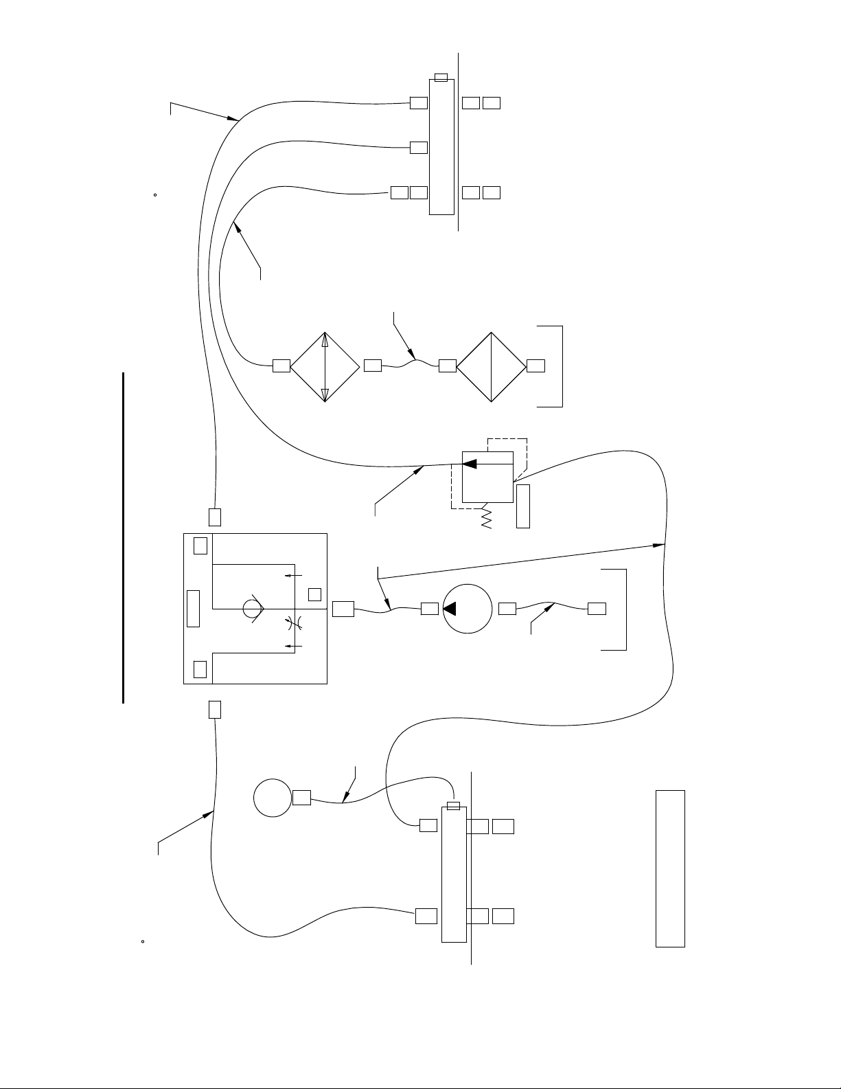
MANIFOLD
10
END TO RETURN
HOSE 4646170
90
HOSE
4646086
HOSE
4646086
RETURN PORTS
COOLER
EX
IN
FLOW
CF
HOSE
4641067
4646200 CB35XL HYDRAULIC SCHEMATIC
HOSE 4646055
RELIEF
HOSE
6040057
TANK
TANK
FILTER
1
2
MANIFOLD
HOSE 4646170
END TO PRESSURE
90
GAGE
PRESSURE PORTS
ALL HOSES ARE IN KIT
4646209.
Page 11
4646209 HOSE KIT, CB35
11
34.0
31.2
20.1
1
2
3
23.6
16.6
ITEM PART NO. QTY. DESCRIPTION
1 6040057 1 Hose Assy., 1 x 34"
3202317 2 Fitting, 1" FJIC to 1" Hose Barb
3200135 2 Hose Clamp #16
2 4641067 3 Hose Assy., 5/8" x 31-1/4"
3202075 2 5/8"FJICS x 5/8" Parkrimp Hose End Fitting
3 4646170 2 Hose Assy., 5/8" x 20"
3201883 1 5/8" FJIC Parkrimp, 90 Deg.
3202075 1 5/8"FJICS x 5/8" Parkrimp Hose End Fitting
4 4646086 2 Hose Assembly, 3/4" x 23.6"
3201989 2 Fitting, 3/4" F.JIC to 3/4" Hose Barb
3200135 2 Hose Clamp #16
5 4646055 1 Hose Assembly, 1/4" x 16.6"
3200128 1 Fitting, 1/4" F. JIC to 1/4" Hose Crimp
3200145 1 1/4 MPT - 1/4 Hose Crimp
3201110 1 Coupling, 1/4" NPT
4
5
Page 12

4646200 CB35XL ELECTRIC SCHEMATIC
12
4643022
BLACK GROUNDS TO ENGINE
RED TO MATING CONNECTOR
ENGINE
RED
BLACK
23
12
SWITCH
11
24
4646016
GROUND
TO ENGINE
MOUNTING BOLT
STOP
4646015
TO COIL
+ -
BATTERY
FOR EASE OF ASSEMBLY, ATTACH WIRES TO STOP SWITCH
BEFORE INSTALLING IN PANEL.
Page 13
4600203 GAS TANK ASSEMBLY
13
4
3
2
1
7
6
ITEM PART NO. QTY. DESCRIPTION
1 6010869 1 Fuel Tank, 4.4 Gallon
2 2506716 1 Grommet
3 2502484 1 Roll Over Vent, 1/4" Hose Barb
4 2503294 1 Fuel Tank Cap, W/Gage
5 3200418 1 Adapter, 1/4" M. Pipe to 1/4" M. JIC
6 3200108 1 Ball Valve, 1/4" NPT
7 3200012 1 Street Elbow, 1/4" NPT
8 2900022 4 Flat Washer, 5/16" SAE
9 2900031 4 Lock Washer, 5/16" Split
10 2900019 4 Cap Screw, Hex Hd., 5/16-18 x 3/4"
5
8
9
10
Page 14

4646173 HYDRAULIC TANK ASSEMBLY
14
22
23
21
13
6
18
17
16
15
14
11
8
5
10
12
19
20
4
2
1
3
7
9
2
3
Page 15

4646173 HYDRAULIC TANK ASSEMBLY
15
ITEM PART NO. QTY. DESCRIPTION
1 4640120 1 Hydraulic Tank Weldment
2 3200409 2 Street Elbow, 1" NPT
3 3200427 2 Nipple, 1" NPT x 4"
4 3200289 1 Elbow, 1" M. Pipe to 1" M. JIC
5 3200431 1 NIpple, 1"MPT - 3/4" MPT
6 2400166 1 Sight Gauge, Liquid Level
7 3200160 1 Plug, 1/2-14 NPT
8 2703290 1 Filter Head, 3/4" NPT
9 3201175 1 Hydraulic Filter Element
10 3200156 1 Street Elbow, 1/8" NPT
11 3200502 1 Gauge, Hydraulic Pressure
12 3200097 1 Adapter, 3/4" M. JIC to 3/4" M. Pipe
13 2900441 10 Rivet Nut, 1/4-20 Round
14 4646083 1 Gasket, Hyd Tank
15 4640121 1 Cover, Hydraulic Tank
16 2800459 1 Thermometer, 2", 0 - 200 F
17 2401305 1 Filler/Breather Cap (Top Mount)
2900339 6 Cap Screw, Hex Hd., M5 x 12mm
18 2900567 2 Flat Washer, 5/16" USS
19 2900031 2 Lock Washer, 5/16" Split
20 2900138 2 Cap Screw, Hex Hd., 5/16-18 x 1"
21 2900024 10 Lock Washer, 1/4" Split
22 2900023 10 Cap Screw, Hex Hd., 1/4-20 x 5/8"
23 1800535 1 Decal, "Hydraulic Fluid Only"
Page 16

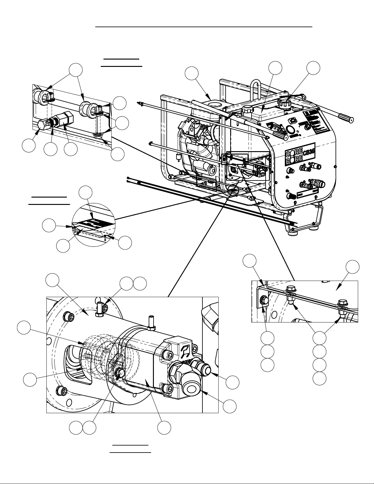
4646207 CB35XL PANEL ASSEMBLY
16
6X
2
3
4
32
7
44
42
1
45
36
228
35
33
38
39
43
41
34
78
79
19
21
22
25
36
37
12
40
13
24
20
23
26
10
7
3X
31
17
18
16
15
5
27
30
29
710
29
14
11
Page 17

4646207 CB35XL PANEL ASSEMBLY
17
ITEM PART NO. QTY. DESCRIPTION
1 4646141 1 Instrument Panel
2 2900022 8 Flat Washer, 5/16" SAE
3 2900031 6 Lock Washer, 5/16" Split
4 2900138 6 Cap Screw, Hex Hd., 5/16-18 x 1"
5 4645054 1 Manifold, SAE O-Ring, 5/8 & 3/4" Ports
6 4646101 1 Manifold, 3/4 NPT
7 2900009 20 Flat Washer, 1/4" SAE
8 2900667 4 Cap Screw, Hex Hd., 1/4-20 x 3"
9 2901001 4 Cap Screw, Hex Hd., 1/4-20 x 2-1/2"
10 2900010 10 Lock Nut, 1/4-20 Nylon
11 3200479 1 Plug, 3/4" NPT Square Head
12 3200097 1 Adapter, 3/4" M. JIC to 3/4" M. Pipe
13 3200417 1 Elbow, 3/4" F. JIC to 3/4" M. JIC
14 3200082 2 5/8" MJIC TO 3/4" MPT
15 3200626 1 Adapter, 5/8" O-Ring to 1/4" M. JIC
16 3201241 1 Elbow, 1/4" M. JIC to 1/4" F. JIC
17 3202077 1 5/8 MJIC - 3/4" MOR, 90 Deg.
18 3202079 1 5/8" O-Ring - 5/8" MJIC
19 3200330 1 Adapter, 3/4" M. Pipe to 3/4" O-Ring
20 3201899 1 Adapter, 1/2" MPT to 3/4" O-Ring
21 3200105 1 Nipple, 1/2" Q.D.
22 3200101 1 Nipple, 3/4" Quick Disconnect
23 3200137 1 Hex Nipple, 3/4" NPT
24 3200383 1 Nipple, Hex, 3/4" MPT TO 1/2" MPT
25 3200100 1 Coupler, 3/4" Quick Disconnect
26 3200104 1 Coupler, 1/2" Q.D.
27 2400307 1 Heat Exchanger
28 2900303 2 Lock Nut, M8-1.25 Nylon Insert
29 3200400 2 Elbow, 3/4" O-Ring to 3/4" Male JIC
30 3202083 1 Valve, Flow Control, 16 GPM
31 3202061 3 Fitting, 5/8" MORB x 5/8" MJIC x 90 DEG
32 2900245 2 Cap Screw, Soc. Hd., 1/4-20 x 2-5/8"
33 3202413 1 Gauge, Hydraulic, 4000 PSI
34 2801367 1 E-Stop Switch
35 2801502 1 Tach/Hour Meter, W/#6 Screws
36 3201659 2 Fitting, 3/4" M. Pipe to 3/4" M. Garden
37 3200177 1 Fitting, 3/4" F. Garden Union Swivel
38 2500204 1 Plug, 1/2" Hole
39 2503749 1 Plug, 5/16" Hole (Tapered)
40 1800536 1 "Return" Decal
41 1800941 1 Decal, Hydraulic Power Supply
42 1800531 1 "Hyd. Pressure" Decal
43 1801907 1 Decal, Stop
44 1801852 1 Decal, CB35 Flow Control
45 1801366 1 Decal, Core Bore CB35
Page 18

4400298 AIR TO OIL COOLER OPTION, CB35XL
18
DETAIL A
SCALE 1 : 1.5
13
15
10
33
9
75
32
8
16
17
21
3
13 14
12
20
18
18
19
GROUND
STUD
4
9
5
22
23
11
26
TO
FILTER
31
2524
29
TO HEAT
EXCHANGER
16
27
28
30
Page 19

4400298 AIR TO OIL COOLER OPTION, CB35XL
19
1) ATTACH WIRES TO RELAY BEFORE
BOLTING TO PANEL.
2) REMOVE ORIGINAL HOSE FROM
HEAT EXCHANGER TO FILTER.
3) REPLACE ELBOW AT LOWER
HEAT EXCHANGER PORT W/ 3200458.
4) ADD ELBOW 3200417 TO FILTER.
5) INSTALL LONGER HOSES.
6) SECURE WIRES AND HOSES WITH
WIRE TIES.
RADIATOR
TEMPERATURE
SWITCH
4641154
+ -
BATTERY
GREEN
RED
GREEN
BLACK
23
24
RED
BLACK
4641155
85
86
12
11
STOP
SWITCH
4641157
8787A
RELAY
30
RED
FUSE
4641156
GROUND
STUD
ITEM
PART
NO.
1 4646156 1 CB-XL Frame Assembly
2 4646141 1 Instrument Panel
3 2400308 1 Radiator, 12 Volt, 1" SAE Ports
4 4641097 1 Heat Shield
5 4645104 1 Gasket
5 3200112 2 Elbow, 1" O-Ring to 3/4" M. JIC
7 2800875 1 Temperature Switch, 3/8 NPT
8 4641159 1 Radiator Guard
9 2900567 8 Flat Washer, 5/16" USS
10 2900289 4 Cap Screw, Hex Hd., 5/16-18 x 2-1/4"
11 2900039 4 Lock Nut, 5/16-18 Nylon
12 2800144 1 Relay, 50 Amp, 12 V, SPDT
13 2900016 2 Flat Washer, #10 USS
14 2900159 1 Machine Screw, Rd. Hd., #10-24 x 5/8"
15 2900017 1 Lock Nut, #10-24 Nylon
16 2800481 1 Fuse Holder
QTY. DESCRIPTION
ITEM
PART
NO.
17 2803014 1 Fuse, 15 Amp, Slo Blow
18 2900009 2 Flat Washer, 1/4" SAE
19 2900024 1 Lock Washer, 1/4" Split
20 2900008 1 Cap Screw, Hex Hd., 1/4-20 x 1"
21 2900125 1 Hex Nut, 1/4-20
22 4641154 1 Wire Assy., 4 Wire
23 4641155 1 Wire Assy., Red & Grn, 14 Ga.
24 4641156 1 Wire Assy, Black & Red
25 4641157 1 Wire Assy., 20 Ga., Brn, 8-1/2"
26 2800068 4 Wire Tie, 7-1/2"
27 3200417 1 Elbow, 3/4" F. JIC to 3/4" M. JIC
28 3200458 1 3/4" O-Ring to 3/4" MJIC, 45 Deg.
29 4643016 1 Hose Assembly, 3/4" x 70"
30 4643017 1 Hose Assembly, 3/4" x 58"
31 2800278 8 Wire Tie, 14"
32 1800537 1 Label, HOT
33 1801707 1 Decal, Caution, Fan
QTY. DESCRIPTION
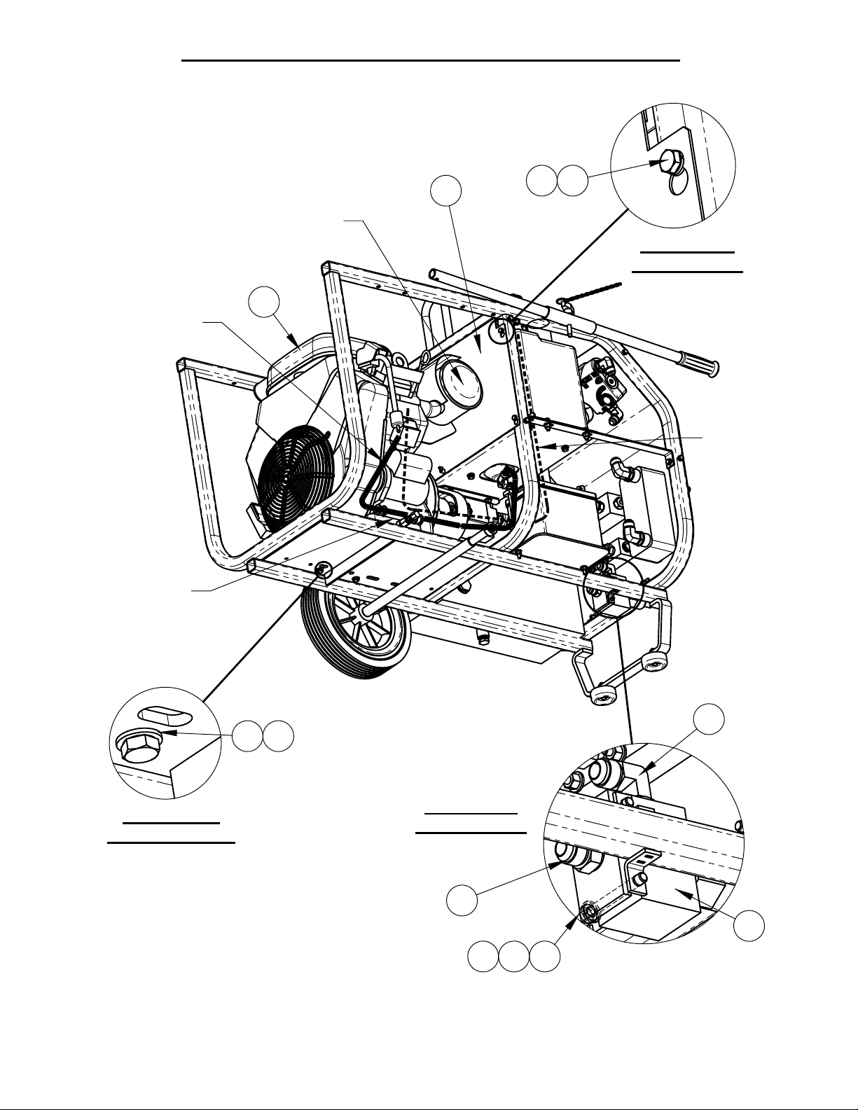
Page 20

FLOW
20
CONTROL
EMERGENCY
STOP
QUICK
RELIEF
WATER
VALVE
CONNECTIONS
OILFILTER
GAGE
CHOKE&
THROTTLE
GASLINEVALVE
BELOWTANK
KEYSTART
Page 21

GENERAL SAFETY PRECAUTIONS
21
WARNING: Do not operate power unit without reading this entire manual and the engine
operation manual first. Keep manuals with power unit at all times for reference.
This manual describes the operating procedures, care, maintenance, adjustments, and safety
precautions for proper use of this machine. This equipment is intended for industrial
applications by experienced operators. It is to be operated in conformance with applicable
federal, state, and local codes or regulations pertaining to safety, air pollution, noise, etc.
Tool operators and maintenance personnel must always comply with the safety precautions
given in this manual and on the stickers and tags attached to the equipment.
These safety precautions are given for your safety. Review them carefully before operating
the tool and before performing general maintenance or repairs.
Supervising personnel should develop additional precautions relating to the specific work
area and local safety regulations.
In addition to this manual, read and understand safety and operating instructions in the
Engine Operation Manual furnished with the Power Unit in addition to this manual.
Establish a training program for all operators to ensure safe operation.
Do not operate the power unit unless thoroughly trained or under the supervision of an
instructor.
Do not inspect or clean the power unit while it is running.
Always use hoses and fittings rated at a minimum 3000 p.s.i. (206.9 bar) with a 4 to 1
safety factor for pressure lines.
Be sure all hose connections are tight.
Make sure all hoses are connected for correct flow direction to and from the tool being
used.
Do not inspect hoses and fittings for leaks by using bare hands. “Pin-hole” pressure leaks
can penetrate the skin.
Never operate the gas power unit in a closed space. Inhalation of engine exhaust can
be fatal.
Do not operate a damaged or improperly adjusted power unit.
Never wear loose clothing that can get entangled in the working parts of the power unit.
Keep all parts of your body away from the working parts of the power unit.
Page 22

Always wear appropriate safety equipment such as goggles, ear protection, head
22
protection and safety shoes. Certain tools used in conjunction with the power unit may
require other safety equipment such as breathing filters.
Keep clear of hot engine exhaust.
Do not add fuel to the power unit while the power unit is still running or is still hot.
Do not operate the power unit if a gasoline odor is present.
Do not use flammable solvents around the power unit engine.
Do not operate the power unit within 3 ft. (1 meter) of buildings or flammable objects.
Allow the engine to cool before storing the unit in an enclosed area.
To avoid personal injury or equipment damage, all tool repair, maintenance and service
must only be performed by authorized and properly trained personnel.
IMPORTANT: The red stop button at the front panel will immediately stop the engine
and radiator fan. Hydraulic pressure and flow will go to zero. This button must be in
the out position to start the engine.
DANGER: Improper use or alteration of this equipment may be extremely hazardous.
SAFETY SYMBOLS
Safety symbols are used to emphasize actions which could result in a life-threatening
situation, bodily injury, or damage to equipment.
Always observe safety symbols. They are included for your safety and for the protection of
the tool.
! DANGER !
This safety symbol may appear
on the tool. It is used to alert the
operator of an action that could
place him/her or others in a life
threatening situation.
!WARNING: !
This safety symbol appears
in these instructions to identify
an action that could cause bodily
injury to the operator or to other
threatening situation.
! IMPORTANT !
This safety symbol appears in
these instructions to identify an
an action or condition that could
result in damage to the tool or
other equipment.
Page 23

DESCRIPTION AND SPECIFICATIONS
23
Pump: Gear, pump rotation is clockwise (motor is CCW).
Maximum GPM: 17.2 GPM (65.1L/M) at no load, 4000 RPM. Flow will decrease as
pressure approaches the relief setting and as engine RPM drops under load.
Hydraulic Fluid Tank Capacity: 11 gallons (41.6Liters)
Hose Couplings: Bruning quick disconnect, 3/4 inch & ½ inch
Relief Pressure: Factory set at 3000 PSI /206.9 Bar (at valve outlet port). Do not exceed
3000 PSI. Adjustable to 1200 PSI / 83Bar. At relief setting, all flow is to tank and none to tool.
Engine: Briggs & Stratton 35 hp (Gross), Air-cooled, gasoline fueled, no load RPM: 4000.
Fuel Tank Capacity: 5 gallons.
This unit is compatible with most hydraulically driven sawing and drilling components. The
system may not be compatible with components of some manufacturers.
The power unit was inspected and operated before shipment and should not require any
additional adjustments prior to its initial use.
Hydraulic Fluid: The reservoir of the
hydraulic power unit must be full prior to
start-up. The use of high quality petroleum
based hydraulic oil with the following
properties is recommended:
Anti-wear
Low foaming
Rust and oxidation inhibitors
Wide temperature range
Fluid viscosity: 8-1000 Centistokes
(52-4600 SUS). The unit is shipped
with an ISO 46 Viscosity grade
(8Cs/52SUS @ 212F/100C and
46Cs/210SUS @ 104F/40C).
The oil must be kept free of contamination
to avoid damage to system components.
The strainer in the fill cap must always be
in place when adding oil. Quick
disconnects must be cleaned before
connections are made.
Control Valve: The pressure
compensated flow control valve on this unit
allows full flow control while the gas engine
remains at its most efficient wide-open
throttle. This allows a higher operating
pressure at all flows.
Flow settings
: CCW, all flow routed to
tank. Flow to tool increases as valve
rotates clockwise.
Relief Valve: Relief pressure can be
adjusted by using an Allen wrench at the
relief cartridge, which is mounted just
below the front panel. The relief can be set
as low as 1200 psi; do not exceed 3000
psi. To adjust, the flow control must be set
at MAX and no tool should be attached.
This will force all flow over relief. The relief
should rarely need adjustment. Higher
relief may cause the engine to stall.
Hydraulic Oil Cooler and Radiator: The
power unit is equipped with a brazed plate
style oil cooler and a radiator option is
available. Whenever possible, water
should be passed through the cooler
before being used for dust control or blade
& bit cooling. Some tools will automatically
shut off water flow when not actively
cutting, drilling, etc. This may result in
higher oil temperatures if the power unit
continues to run for long periods without
cooling water. The optional radiator fan will
come on automatically when the oil
temperature reaches ~ 120 F. (49 C.) and
continue to run until the oil cools, even if
the engine is shut off. The fan will stop
whenever the emergency stop switch is
used.
IMPORTANT: If there is a risk of frost
the water must be drained from the
cooler to prevent damage by freezing.
Page 24

24
HOSES: Large diameters and short
lengths are preferred and offer the highest
system efficiency. If one is operating 50 ft
(15.2M) from the power source, there is
also a 50 ft (15.2M) return for a 100 ft
(35.5M) total hose length. With 15 GPM
and oil at 100 deg. F (37.8C), this could
result in a 400 psi (27.5 Bar) pressure loss
with ½” hose and a 140 psi (9.6 Bar) loss
with 5/8” hose. Pressure loss will change
dramatically with oil temperature.
OPERATING INSTRUCTIONS
Operator Responsibilities
It is the operator’s responsibility to use this
unit and any attached tools under safe
working conditions and to follow proper
safety procedures for themselves, coworkers, observers, and the public at large.
The operator must be aware of the
machine’s capabilities and limitations and
follow the safety precautions in each
section of this manual. Periodic
maintenance is required, in accordance
with the instructions herein, to promote
safe and reliable operations.
WARNING
immediate work area.
Wear approved:
Safety glasses
Ear protection
Hard hat
Gloves
Safety shoes
: Keep bystanders out of the
Any other protective equipment
required for compliance with standard
safety practices or federal, state, and
local codes and regulations
HOSE CONNECTIONS: It is best to
connect the hoses to the unit before
starting as even very low residual pressure
can make hose installation more difficult.
Push couplings together until you hear it
click. Turn locking ring of coupling to the
secured position.
ENGINE: Make sure that the engine
crankcase is filled with oil to the proper
level! Refer to your engine manual for oil
checking and changing procedures, along
with oil specifications, etc.
IMPORTANT: Operating the engine
without oil will ruin the engine.
FUEL: Use regular grade unleaded
gasoline to fuel the engine. Premium
grade may be used if necessary. Fill the
tank when the engine is off and has been
allowed to cool. Care should be taken to
prevent spilling fuel. Do not overfill the
fuel tank. Always leave enough space for
expansion due to environmental heating.
WARNING: In the event of fuel spillage,
do not start the engine or operate any
nearby electrical component until the
spilled fuel has been removed.
Starting Procedure:
Set the flow control valve to zero.
Open the fuel shut off valve below the
gas tank.
Be certain the emergency off switch
has been pulled out.
Set throttle at about 1/3, set choke if
necessary (cold engine). Turn key to
start and release. Refer to engine
manual for details of control functions.
Let engine warm and gradually set the
throttle to maximum.
DANGER: Exhaust from the engine
contains carbon monoxide, a
poisonous, odorless, invisible gas,
which can cause serious illness or
death. Do not operate the engine
where ventilation is restricted. Open
windows and doors may not be
sufficient to prevent this hazard.
Page 25

25
Heating Cold Oil: Forcing the oil over
relief will quickly increase the oil
temperature. With no tool connected to the
unit, move the valve setting toward 10.
This will force an increasing percentage of
oil over relief. Heat cold oil to room
temperature or ~100F/38C maximum. Cold
oil greatly increases pressure loss in hoses
and fittings and may affect tool operation.
Maintaining Oil Temperature: With an
ample water supply and the radiator, it is
unlikely overheating will be an issue except
in the most extreme ambient temperatures.
To force high oil temperatures down, run
the unit with the flow control set to zero.
This unloads the unit yet circulates oil
through the cooling system. The rate of
cooling will depend on the ambient
temperature and how much water is being
passed through the cooler.
Some control valves at the external tool
may create backpressure and heat even
when off. It is best to set the flow control to
zero or shut the power unit down to avoid
heating and conserve energy.
IMPORTANT: Monitor the thermometer
at the top of the hydraulic tank.
Maximum recommended oil
temperature is 180 degrees Fahrenheit
(82 deg C).
Shutting Down:
Shift the flow control valve to zero to
unload the system.
Throttle the engine back to a low RPM.
Turn the key to the off position.
IMPORTANT
front panel will immediately stop the
engine and radiator fan. Hydraulic
pressure and flow will go to zero. This
button must be in the out position to
start the engine.
: The red stop button at the
OPERATING DRIVEN
EQUIPMENT
The operator must know the hydraulic
requirements and limitations of the driven
equipment and the appropriate
adjustments must be made on the controls.
The introduction of other control devices
may cause system heating or may render
the system inoperative.
IMPORTANT: This power unit is
equipped with a positive displacement
gear pump. All tools must be equipped
with a control valve that allows flow
directly to return ports when not in use.
Blocking oil flow or abruptly
disconnecting the tool can send flow
over relief and potentially overheat the
system.
Instructions supplied with the driven
equipment must be followed to ensure
correct connection and operation of each
individual piece of equipment. Equipment
supplied by Diamond Products will be
capable of being connected correctly and
will be compatible with this power unit,
providing neither has been modified from
original factory configuration. With
equipment of other manufacturers, it will be
necessary to determine the following:
Correct direction of flow through the
equipment.
Correct pressure and flow required by
the equipment.
Compatibility of any valves or circuitry
and quick disconnects. Some handheld equipment uses a trigger control,
which is operated frequently. These
valves must be of the open center type
for correct operation.
IMPORTANT
must be clean when connecting hoses
and devices. Failure to thoroughly
clean may result in contamination and
premature failure of system or tool
components.
: The quick disconnects
Page 26

MAINTENANCE
26
INSTRUCTIONS
Oil Filter: change the filter when
indicated by the gage at the filter.
Oil Change: establishing an oil analysis
program is the preferred method of
determining oil condition and when to
change it. If the oil is kept clean, dry,
and operated at moderate
temperatures, it can last for several
years. With no analysis program an oil
change every 200 hours is
recommended. See the section
Hydraulic Fluid for specifications. A ½”
pipe thread oil drain port is at the
bottom of the hydraulic tank.
Engine Oil: Change engine oil and filter
and perform other routine maintenance
as recommended in the engine
operation manual.
Inspect hoses, couplings, and fittings
daily for leaks, tighten as required.
Clean quick disconnects frequently.
Replace any leaking or defective
components immediately.
Check hydraulic oil level daily. Fill tank
to upper end of sight tube with unit off.
TROUBLESHOOTING
PROBLEM POSSIBLE SOLUTIONS
Engine will not start.
Radiator fan does not run (Optional
on gas units).
Low oil flow.
System builds high pressure with
flow control valve set to zero.
Keep this manual and the engine manual readily available at all times for reference.
1) Pull out emergency stop button.
2) Open gas line valve below gas tank.
3) Dead battery?
4) Low engine oil?
1) Oil must be >120 F. (49C.)
2) Check fuse at front panel.
3) Electrical connectors firmly attached?
4) Dead Battery?
Check engine RPM at tachometer on front panel.
Adjust governor to 4000 RPM, at no load, if required.
See engine manual.
Contamination may have plugged an orifice in the CF
port of the flow valve. Detach the valve from the front
panel and remove the fitting from the CF port. A .015”
orifice should be visible at the bottom of the port. Push
a fine wire through the orifice and re-install.
Page 27

CBPOWERPACKFLOWANDPRESSURERATING
27
CBPOWERPACK
MODEL
MAXIMUMNO
LOADFLOW
GPM/LPM
RELIEF
SETTING
PSI/BAR
15Electric 12.75/48.2 2100/145
18BriggsVanguard 11.6 /43.9 2850/196.5
20Electric 14.9/56.4 2400 /165.5
21Honda 14.1 /53.2 2600 /179.3
30Electric 20.4/77.2 2300 /158.6
35BriggsVanguard 17.2 /65.1 3000 /206.9
Maximumnoloadflowisbasedonpumpandmotormanufacturer’s
specificationsforpumpdisplacementandnoloadRPM.Reliefissettoinsuregas
enginescannotreachtheirstalltorqueandelectricmotorswillnotexceedthe
recommendedcurrentlimit.
MAXNO
LOADFLOW
FLOW
USEABLEFLOW/PRESSURE
BELOWDARKLINE
>>>PRESSURE>>> CRACKING
RELIEF
PRESSURE
Flowdecreasesasengine/motorRPMdropsunderload.Reliefvalvesbeginto
openandshuntflowtotankat75‐80%ofthereliefsetting(crackingpressure).
Thisfurtherreducesflowtothetool.Atrelief,allflowisdirectedtotank.
IssuedAugust2011
Page 28

EQUIPMENT AND PARTS
WARRANTY
Diamond Products warrants all equipment manufactured by it against defects
in workmanship or materials for a period of one (1) year from the date of
shipment to Customer.
The responsibility of Diamond Products under this Warranty is limited to
replacement or repair of defective parts at Diamond Products’ Elyria, Ohio
factory, or at a point designated by it, of such parts as shall appear to us upon
inspection at such parts, to have been defective in material or workmanship,
with expense for transportation and labor borne by Customer.
In no event shall Diamond Products be liable for consequential or
incidental damages arising out of the failure of any Product to operate properly.
Integral units such as engines, electric motors, batteries, transmissions,
etc., are excluded from this Warranty and are subject to the prime
manufacturer’s warranty.
THIS WARRANTY IS IN LIEU OF ALL OTHER WARRANTIES, EXPRESSED
OR IMPLIED, AND ALL SUCH OTHER WARRANTIES ARE HEREBY
DISCLAIMED.
333 Prospect Street, Elyria, Ohio 44035
(440) 323-4616 (800) 321-5336 Fax (440) 323-8689
www.diamondproducts.com
Printed in U.S.A.
 Loading...