

Page 1

CONCRETE SAW
PARTS LIST
MODEL
CB20E-XL
DECEMBER 2013
Part #1801372
Page 2
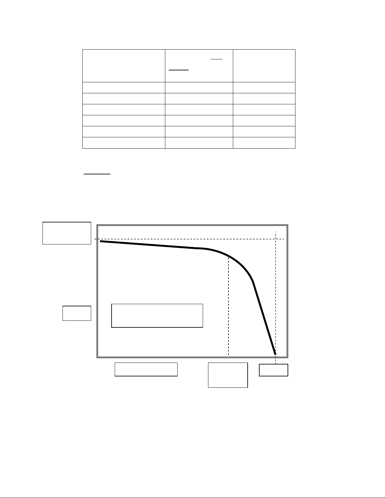
CBPOWERPACKFLOWANDPRESSURERATING
CBPOWERPACK
MODEL
MAXIMUMNO
LOADFLOW
GPM/LPM
RELIEF
SETTING
PSI/BAR
15Electric 12.75/48.2 2100/145
18BriggsVanguard 11.6 /43.9 2850/196.5
20Electric 14.9/56.4 2400 /165.5
21Honda 14.1 /53.2 2600 /179.3
30Electric 20.4/77.2 2300 /158.6
35BriggsVanguard 17.2 /65.1 3000 /206.9
Maximumnoloadflowisbasedonpumpandmotormanufacturer’s
specificationsforpumpdisplacementandnoloadRPM.Reliefissettoinsuregas
enginescannotreachtheirstalltorqueandelectricmotorswillnotexceedthe
recommendedcurrentlimit.
MAXNO
LOADFLOW
FLOW
USEABLEFLOW/PRESSURE
BELOWDARKLINE
>>>PRESSURE>>> CRACKING
RELIEF
PRESSURE
Flowdecreasesasengine/motorRPMdropsunderload.Reliefvalvesbeginto
openandshuntflowtotankat75‐80%ofthereliefsetting(crackingpressure).
Thisfurtherreducesflowtothetool.Atrelief,allflowisdirectedtotank.
IssuedAugust2011
Page 3

Table of Contents
Description Page No.
1. 230/460 Volt Hydraulic Power Supply ..................................................4
2. 190/380 Volt Hydraulic Power Supply ..................................................8
3. 575 Volt Hydraulic Power Supply .........................................................12
4. Hydraulic Schematic .............................................................................16
5. Hose Kit ..................................................................................................17
6. Hydraulic Tank Assembly .....................................................................18
7. Control Panel Assembly .......................................................................20
8. 208-460 Volt Starter Box Assembly .....................................................22-25
9. 380 Volt Starter Box Assembly ............................................................26-29
10. 575 Volt Starter Box Assembly ............................................................30-33
11. Component Locations ..........................................................................35
12. Safety Precautions ...............................................................................36
13. Descriptions and Specifications .........................................................38
14. Operating Instructions ........................................................................39
15. Operating Driven Equipment & Maintenance Instructions ...............40
16. Troubleshooting ...................................................................................41
17. Warranty ………………………………………………………….Rear Cover
Page 4
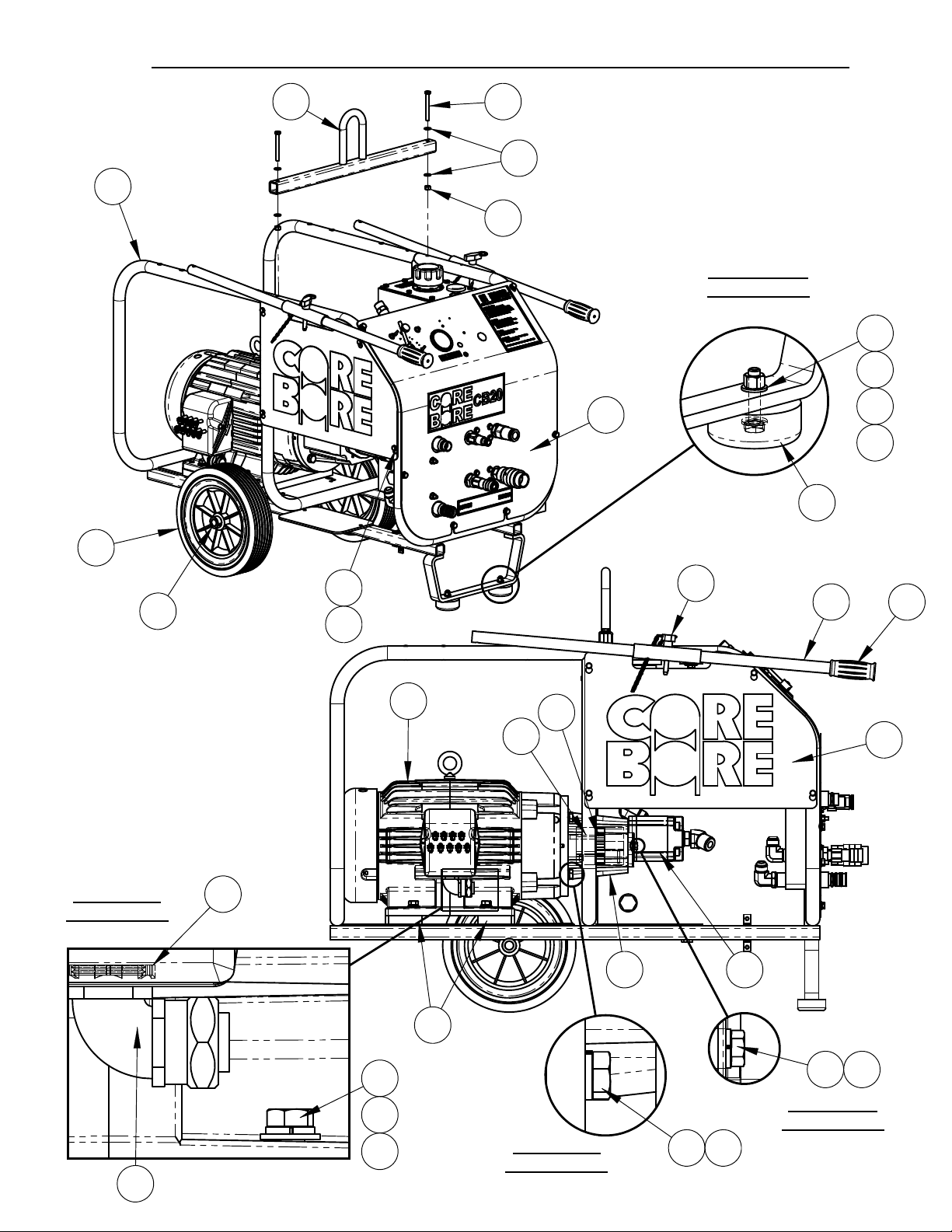
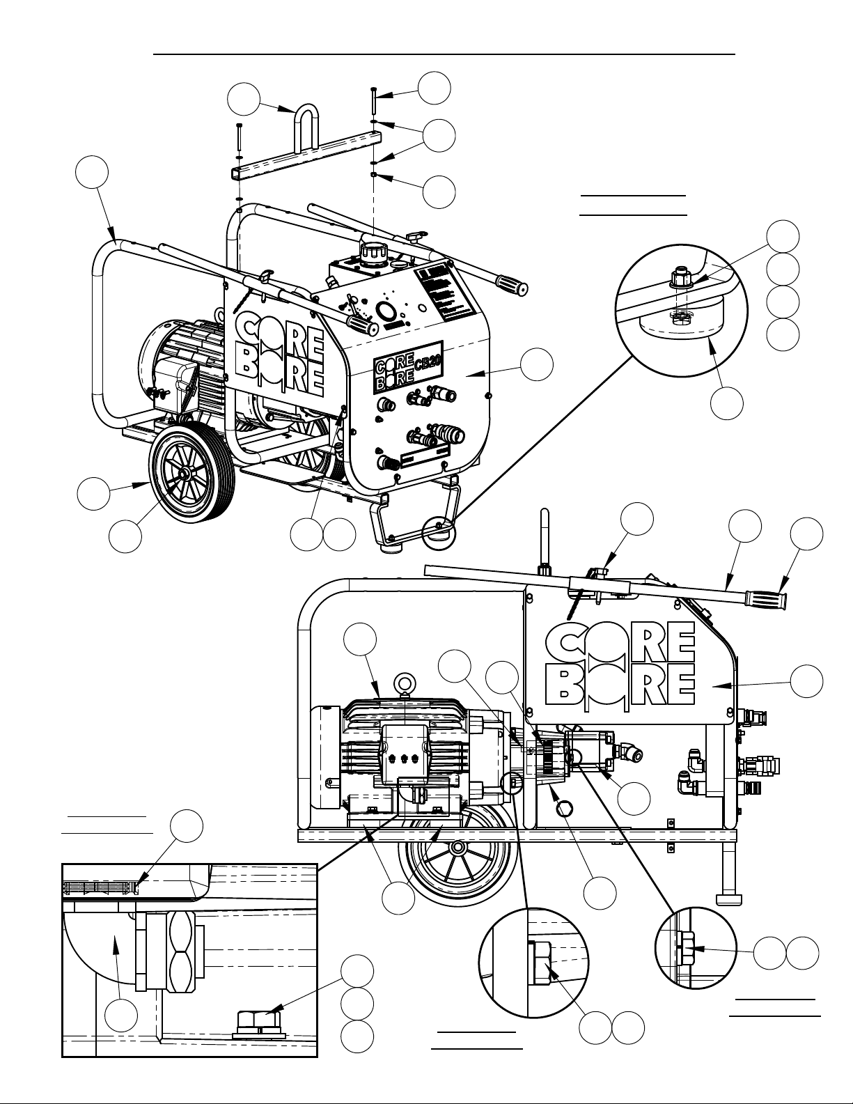
4646175 CB20 HYDRAULIC POWER SUPPLY 230/460 VOLT
4
38
1
39
5
7
DETAIL AA
SCALE 1 : 3
5
5
25
4
2
6
7
3
DETAIL A
SCALE 1 : 2
13
14
28
33
4X
18
17
16
12
36
34 35
20
15
2119
8
32
2x
10 11
DETAIL C
SCALE 1 : 2
DETAIL B
SCALE 1 : 2
4x
18 17
Page 5

4646175 CB20 HYDRAULIC
5
POWER SUPPLY 230/460 VOLT
BOM Table
ITEM PART NO. QTY. DESCRIPTION
1 4646156 1 CB-XL Frame Assembly
2 2400643 2 Wheel, 12 x 2-5/8 x 3/4"
3 2400615 2 Set Collar, 3/4"
4 2501767 2 Rubber Bumper
5 2900022 16 Flat Washer, 5/16" SAE
6 2900508 2 Cap Screw, Hex Hd., 5/16-18 x 1-1/2"
7 2900039 8 Lock Nut, 5/16-18 Nylon
8 4646172 2 Spacer Plate, CB20
9 2900473 4 Flat Washer, 3/8" USS
10 2900005 6 Cap Screw, Hex Hd., 3/8-16 x 1"
11 2900006 6 Lock Washer, 3/8" Split
12 4645005 1 Elec. Motor, 20HP, Short Shaft, W/Terminals
13 2800312 1 Connector, 1" Sealtite Elbow
14 2800193 1 Lock Nut, 1"
15 6047959 1 Key, 3/8" Sq. x 2-1/4"
16 2900058 4 Flat Washer, 1/2" SAE
17 2900084 8 Lock Washer, 1/2" Split
18 2900499 8 Cap Screw, Hex Hd., 1/2-13 x 1-1/2"
19 2400309 1 Pump Mount
20 2400167 1 Coupling Assembly, 1-5/8 - 3/4"
21 2600569 1 Pump, 1.0 CI, 2 Bolt SAE
22 3202079 1 5/8" O-Ring - 5/8" MJIC
23 3201881 1 1" MJIC - 3/4" MOR, 45 Deg.
24 4646173 1 Hydraulic Tank Assembly
25 4646171 1 Panel Assembly, CB20
26 4646035 1 Fuel Tank Support
27 2900009 2 Flat Washer, 1/4" SAE
28 2900024 6 Lock Washer, 1/4" Split
29 2900008 2 Cap Screw, Hex Hd., 1/4-20 x 1"
30 2900138 4 Cap Screw, Hex Hd., 5/16-18 x 1"
31 4641098 1 Starter Box Platform
32 4646049 1 Side Panel
33 2900144 4 Cap Screw, Hex Hd., 1/4-20 x 3/4"
34 4646006 2 Handle
35 2500636 2 Handle Grip
36 2900257 2 Lock Pin, T Handle, 3/8"
37 2900053 4 Rivet, 3/32" Dia.
38 4646003 1 Lifting Bar
39 2900248 2 Cap Screw, Hex Hd., 5/16-18 x 3"
40 1800169 1 Serial Number Plate, US
41 4646180 1 Hose Kit, CB20XL, CB35XL
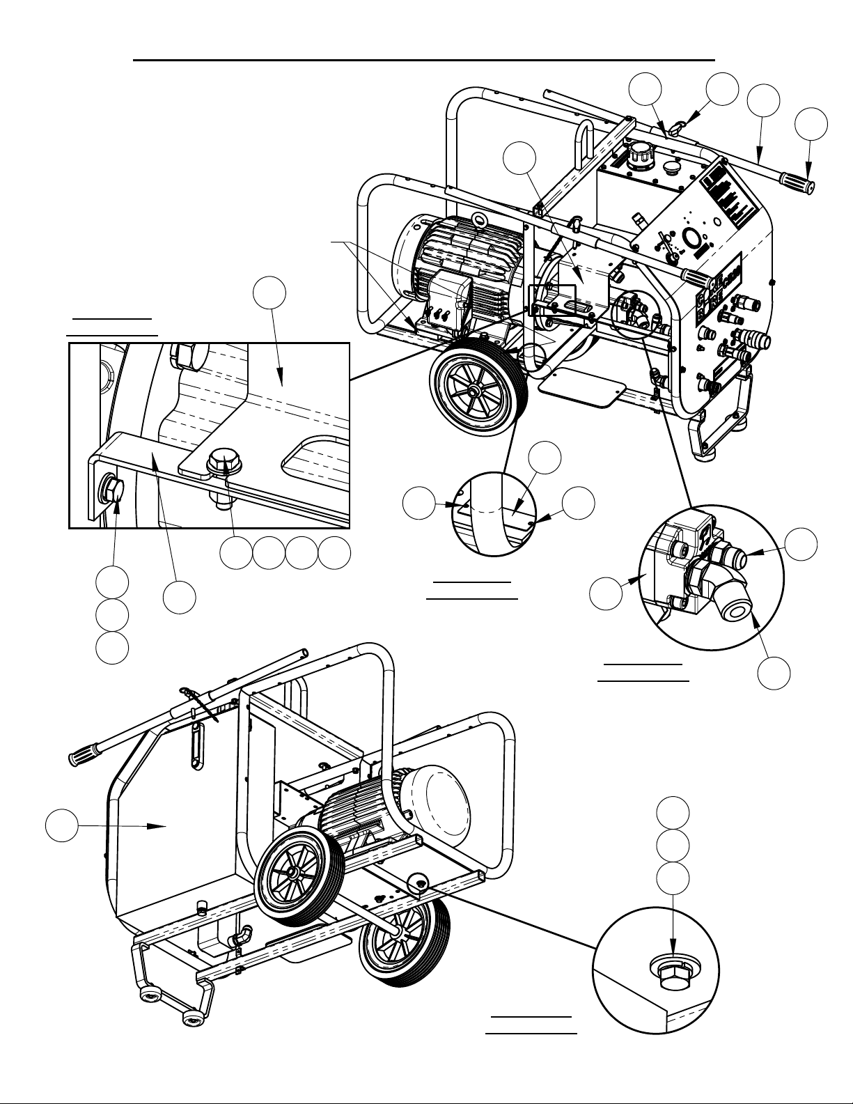
Page 6

4646175 CB20 HYDRAULIC POWER SUPPLY 230/460 VOLT
6
SHIFT SPACERS TO THIS SIDE.
CHAMFERS FACE TO
FRONT AND REAR.
5
4x
7
5
30
DETAIL D
SCALE 1 : 2
31
31
40
37
36
34
35
2x
24
29
28
27
26
37
DETAIL G
SCALE 1 : 4
37
21
DETAIL E
SCALE 1 : 4
4x TO
SPACER
PLATES
22
23
9 11 10
DETAIL F
SCALE 1 : 2
Page 7

4646175 CB20 HYDRAULIC
7
POWER SUPPLY 230/460 VOLT
BOM Table
ITEM PART NO. QTY. DESCRIPTION
1 4646156 1 CB-XL Frame Assembly
2 2400643 2 Wheel, 12 x 2-5/8 x 3/4"
3 2400615 2 Set Collar, 3/4"
4 2501767 2 Rubber Bumper
5 2900022 16 Flat Washer, 5/16" SAE
6 2900508 2 Cap Screw, Hex Hd., 5/16-18 x 1-1/2"
7 2900039 8 Lock Nut, 5/16-18 Nylon
8 4646172 2 Spacer Plate, CB20
9 2900473 4 Flat Washer, 3/8" USS
10 2900005 6 Cap Screw, Hex Hd., 3/8-16 x 1"
11 2900006 6 Lock Washer, 3/8" Split
12 4645005 1 Elec. Motor, 20HP, Short Shaft, W/Terminals
13 2800312 1 Connector, 1" Sealtite Elbow
14 2800193 1 Lock Nut, 1"
15 6047959 1 Key, 3/8" Sq. x 2-1/4"
16 2900058 4 Flat Washer, 1/2" SAE
17 2900084 8 Lock Washer, 1/2" Split
18 2900499 8 Cap Screw, Hex Hd., 1/2-13 x 1-1/2"
19 2400309 1 Pump Mount
20 2400167 1 Coupling Assembly, 1-5/8 - 3/4"
21 2600569 1 Pump, 1.0 CI, 2 Bolt SAE
22 3202079 1 5/8" O-Ring - 5/8" MJIC
23 3201881 1 1" MJIC - 3/4" MOR, 45 Deg.
24 4646173 1 Hydraulic Tank Assembly
25 4646171 1 Panel Assembly, CB20
26 4646035 1 Fuel Tank Support
27 2900009 2 Flat Washer, 1/4" SAE
28 2900024 6 Lock Washer, 1/4" Split
29 2900008 2 Cap Screw, Hex Hd., 1/4-20 x 1"
30 2900138 4 Cap Screw, Hex Hd., 5/16-18 x 1"
31 4641098 1 Starter Box Platform
32 4646049 1 Side Panel
33 2900144 4 Cap Screw, Hex Hd., 1/4-20 x 3/4"
34 4646006 2 Handle
35 2500636 2 Handle Grip
36 2900257 2 Lock Pin, T Handle, 3/8"
37 2900053 4 Rivet, 3/32" Dia.
38 4646003 1 Lifting Bar
39 2900248 2 Cap Screw, Hex Hd., 5/16-18 x 3"
40 1800169 1 Serial Number Plate, US
41 4646180 1 Hose Kit, CB20XL, CB35XL
Page 8
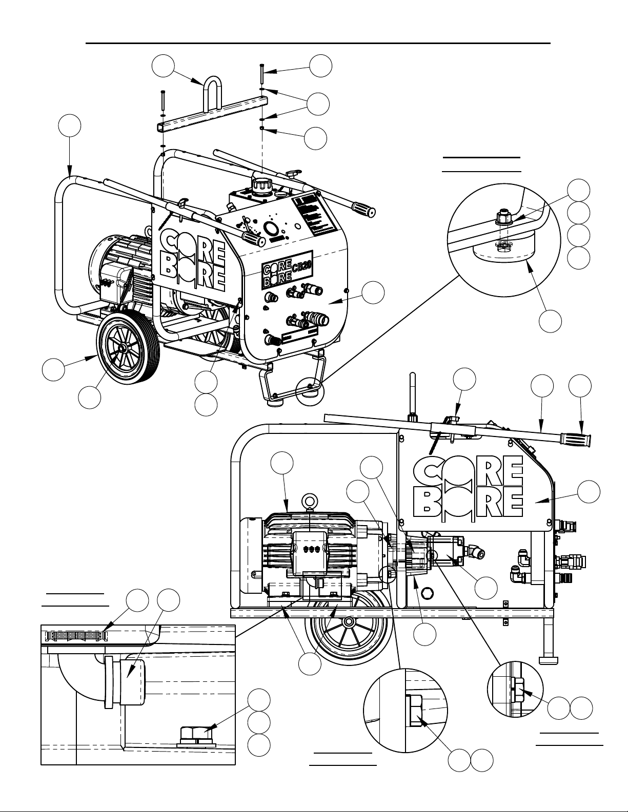
4646183 CB 20 HYDRAULIC POWER SUPPLY 190/380 VOLT
8
38 39
5
1
7
DETAIL AA
SCALE 1 : 3
25
5
5
6
7
4
2
3
DETAIL A
SCALE 1 : 2
14
13
33
28
12
36
20
15
21
19
8
34 35
32
4X
18
17
16
DETAIL B
SCALE 1 : 2
18 174X
2X
10 11
DETAIL C
SCALE 1 : 2
Page 9

4646183 CB20 HYDRAULIC POWER SUPPLY 190/380 VOLT
9
ITEM PART NO. QTY. DESCRIPTION
1 4646156 1 CB-XL Frame Assembly
2 2400643 2 Wheel, 12 x 2-5/8 x 3/4"
3 2400615 2 Set Collar, 3/4"
4 2501767 2 Rubber Bumper
5 2900022 16 Flat Washer, 5/16" SAE
6 2900508 2 Cap Screw, Hex Hd., 5/16-18 x 1-1/2"
7 2900039 8 Lock Nut, 5/16-18 Nylon
8 4646172 2 Spacer Plate, CB20
9 2900473 4 Flat Washer, 3/8" USS
10 2900005 6 Cap Screw, Hex Hd., 3/8-16 x 1"
11 2900006 6 Lock Washer, 3/8" Split
12 4646186 1 Elec. Motor, 20HP, Short Shaft, W/Terminals
13 2800695 1 Cord Grip, 5/8-3/4", 90 Deg.
14 2800193 1 Lock Nut, 1"
15 6047959 1 Key, 3/8" Sq. x 2-1/4"
16 2900058 4 Flat Washer, 1/2" SAE
17 2900084 8 Lock Washer, 1/2" Split
18 2900499 8 Cap Screw, Hex Hd., 1/2-13 x 1-1/2"
19 2400309 1 Pump Mount
20 2400167 1 Coupling Assembly, 1-5/8 - 3/4"
21 2600569 1 Pump, 1.0 CI, 2 Bolt SAE
22 3202079 1 5/8" O-Ring - 5/8" MJIC
23 3201881 1 1" MJIC - 3/4" MOR, 45 Deg.
24 4646173 1 Hydraulic Tank Assembly
25 4646171 1 Panel Assembly, CB20
26 4646035 1 Fuel Tank Support
27 2900009 2 Flat Washer, 1/4" SAE
28 2900024 6 Lock Washer, 1/4" Split
29 2900008 2 Cap Screw, Hex Hd., 1/4-20 x 1"
30 2900138 4 Cap Screw, Hex Hd., 5/16-18 x 1"
31 4641098 1 Starter Box Platform
32 4646049 1 Side Panel
33 2900144 4 Cap Screw, Hex Hd., 1/4-20 x 3/4"
34 4646006 2 Handle
35 2500636 2 Handle Grip
36 2900257 2 Lock Pin, T Handle, 3/8"
37 2900053 4 Rivet, 3/32" Dia.
38 4646003 1 Lifting Bar
39 2900248 2 Cap Screw, Hex Hd., 5/16-18 x 3"
40 1800169 1 Serial Number Plate, US
41 4646180 1 Hose Kit, CB20XL, CB35XL
Page 10
4646183 CB20 HYDRAULIC POWER SUPPLY 190/380 VOLT
10
SHIFT SPACERS TO THIS SIDE.
CHAMFERS FACE TO
FRONT AND REAR.
4X
5
307
31
5
DETAIL D
SCALE 1 : 2
31
40
37
36
34
35
2X
24
29
28
27
26
37
DETAIL F
SCALE 1 : 4
37
21
DETAIL E
SCALE 1 : 4
4X TO
SPACER
PLATES
22
23
10
11
9
DETAIL G
SCALE 1 : 2
Page 11

4646183 CB20 HYDRAULIC POWER SUPPLY 190/380 VOLT
11
ITEM PART NO. QTY. DESCRIPTION
1 4646156 1 CB-XL Frame Assembly
2 2400643 2 Wheel, 12 x 2-5/8 x 3/4"
3 2400615 2 Set Collar, 3/4"
4 2501767 2 Rubber Bumper
5 2900022 16 Flat Washer, 5/16" SAE
6 2900508 2 Cap Screw, Hex Hd., 5/16-18 x 1-1/2"
7 2900039 8 Lock Nut, 5/16-18 Nylon
8 4646172 2 Spacer Plate, CB20
9 2900473 4 Flat Washer, 3/8" USS
10 2900005 6 Cap Screw, Hex Hd., 3/8-16 x 1"
11 2900006 6 Lock Washer, 3/8" Split
12 4646186 1 Elec. Motor, 20HP, Short Shaft, W/Terminals
13 2800695 1 Cord Grip, 5/8-3/4", 90 Deg.
14 2800193 1 Lock Nut, 1"
15 6047959 1 Key, 3/8" Sq. x 2-1/4"
16 2900058 4 Flat Washer, 1/2" SAE
17 2900084 8 Lock Washer, 1/2" Split
18 2900499 8 Cap Screw, Hex Hd., 1/2-13 x 1-1/2"
19 2400309 1 Pump Mount
20 2400167 1 Coupling Assembly, 1-5/8 - 3/4"
21 2600569 1 Pump, 1.0 CI, 2 Bolt SAE
22 3202079 1 5/8" O-Ring - 5/8" MJIC
23 3201881 1 1" MJIC - 3/4" MOR, 45 Deg.
24 4646173 1 Hydraulic Tank Assembly
25 4646171 1 Panel Assembly, CB20
26 4646035 1 Fuel Tank Support
27 2900009 2 Flat Washer, 1/4" SAE
28 2900024 6 Lock Washer, 1/4" Split
29 2900008 2 Cap Screw, Hex Hd., 1/4-20 x 1"
30 2900138 4 Cap Screw, Hex Hd., 5/16-18 x 1"
31 4641098 1 Starter Box Platform
32 4646049 1 Side Panel
33 2900144 4 Cap Screw, Hex Hd., 1/4-20 x 3/4"
34 4646006 2 Handle
35 2500636 2 Handle Grip
36 2900257 2 Lock Pin, T Handle, 3/8"
37 2900053 4 Rivet, 3/32" Dia.
38 4646003 1 Lifting Bar
39 2900248 2 Cap Screw, Hex Hd., 5/16-18 x 3"
40 1800169 1 Serial Number Plate, US
41 4646180 1 Hose Kit, CB20XL, CB35XL
Page 12
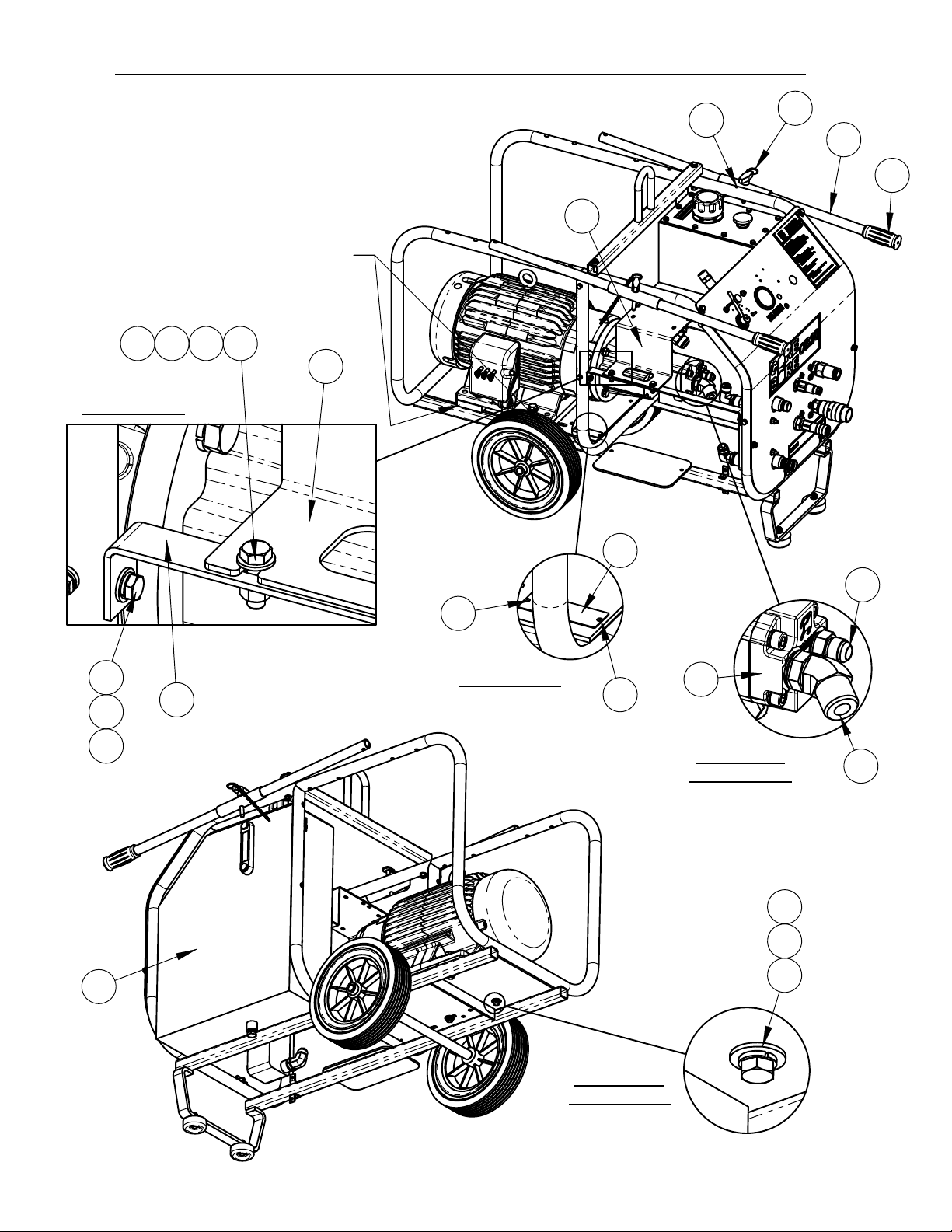
4646178 CB20 HYDRAULIC POWER SUPPLY 575 VOLT
12
38
1
39
5
7
DETAIL AA
SCALE 1 : 3
5
5
6
7
25
4
2
3
DETAIL A
SCALE 1 : 2
14
33 28
12
36
15
8
20
21
19
34
35
32
13
4X
18
17
16
DETAIL B
SCALE 1 : 2
4x
2x
10 11
DETAIL C
SCALE 1 : 2
18 17
Page 13

4646178 CB20 HYDRAULIC POWER SUPPLY 575 VOLT
13
ITEM PART NO. QTY. DESCRIPTION
1 4646156 1 CB-XL Frame Assembly
2 2400643 2 Wheel, 12 x 2-5/8 x 3/4"
3 2400615 2 Set Collar, 3/4"
4 2501767 2 Rubber Bumper
5 2900022 16 Flat Washer, 5/16" SAE
6 2900508 2 Cap Screw, Hex Hd., 5/16-18 x 1-1/2"
7 2900039 8 Lock Nut, 5/16-18 Nylon
8 4646172 2 Spacer Plate, CB20
9 2900473 4 Flat Washer, 3/8" USS
10 2900005 6 Cap Screw, Hex Hd., 3/8-16 x 1"
11 2900006 6 Lock Washer, 3/8" Split
12 4645025 1 Electric Motor, 20HP, W/ Terminals
13 2800312 1 Connector, 1" Sealtite Elbow
14 2800193 1 Lock Nut, 1"
15 6047959 1 Key, 3/8" Sq. x 2-1/4"
16 2900058 4 Flat Washer, 1/2" SAE
17 2900084 8 Lock Washer, 1/2" Split
18 2900499 8 Cap Screw, Hex Hd., 1/2-13 x 1-1/2"
19 2400309 1 Pump Mount
20 2400167 1 Coupling Assembly, 1-5/8 - 3/4"
21 2600569 1 Pump, 1.0 CI, 2 Bolt SAE
22 3202079 1 5/8" O-Ring - 5/8" MJIC
23 3201881 1 1" MJIC - 3/4" MOR, 45 Deg.
24 4646173 1 Hydraulic Tank Assembly
25 4646171 1 Panel Assembly, CB20
26 4646035 1 Fuel Tank Support
27 2900009 2 Flat Washer, 1/4" SAE
28 2900024 6 Lock Washer, 1/4" Split
29 2900008 2 Cap Screw, Hex Hd., 1/4-20 x 1"
30 2900138 4 Cap Screw, Hex Hd., 5/16-18 x 1"
31 4641098 1 Starter Box Platform
32 4646049 1 Side Panel
33 2900144 4 Cap Screw, Hex Hd., 1/4-20 x 3/4"
34 4646006 2 Handle
35 2500636 2 Handle Grip
36 2900257 2 Lock Pin, T Handle, 3/8"
37 2900053 4 Rivet, 3/32" Dia.
38 4646003 1 Lifting Bar
39 2900248 2 Cap Screw, Hex Hd., 5/16-18 x 3"
40 1800169 1 Serial Number Plate, US
41 4646180 1 Hose Kit, CB20XL, CB35XL
Page 14
4646178 CB20 HYDRAULIC POWER SUPPLY 575 VOLT
14
SHIFT SPACERS TO THIS SIDE.
CHAMFERS FACE TO
FRONT AND REAR.
31
DETAIL D
SCALE 1 : 2
3637
34
35
31
24
2X
29
28
27
26
4X
30 7
40
37
5
5
37
22
DETAIL F
SCALE 1 : 4
21
DETAIL E
SCALE 1 : 4
4X TO
SPACER
10
11
23
PLATES
9
DETAIL G
SCALE 1 : 2
Page 15

4646178 CB20 HYDRAULIC POWER SUPPLY 575 VOLT
15
ITEM PART NO. QTY. DESCRIPTION
1 4646156 1 CB-XL Frame Assembly
2 2400643 2 Wheel, 12 x 2-5/8 x 3/4"
3 2400615 2 Set Collar, 3/4"
4 2501767 2 Rubber Bumper
5 2900022 16 Flat Washer, 5/16" SAE
6 2900508 2 Cap Screw, Hex Hd., 5/16-18 x 1-1/2"
7 2900039 8 Lock Nut, 5/16-18 Nylon
8 4646172 2 Spacer Plate, CB20
9 2900473 4 Flat Washer, 3/8" USS
10 2900005 6 Cap Screw, Hex Hd., 3/8-16 x 1"
11 2900006 6 Lock Washer, 3/8" Split
12 4645025 1 Electric Motor, 20HP, W/ Terminals
13 2800312 1 Connector, 1" Sealtite Elbow
14 2800193 1 Lock Nut, 1"
15 6047959 1 Key, 3/8" Sq. x 2-1/4"
16 2900058 4 Flat Washer, 1/2" SAE
17 2900084 8 Lock Washer, 1/2" Split
18 2900499 8 Cap Screw, Hex Hd., 1/2-13 x 1-1/2"
19 2400309 1 Pump Mount
20 2400167 1 Coupling Assembly, 1-5/8 - 3/4"
21 2600569 1 Pump, 1.0 CI, 2 Bolt SAE
22 3202079 1 5/8" O-Ring - 5/8" MJIC
23 3201881 1 1" MJIC - 3/4" MOR, 45 Deg.
24 4646173 1 Hydraulic Tank Assembly
25 4646171 1 Panel Assembly, CB20
26 4646035 1 Fuel Tank Support
27 2900009 2 Flat Washer, 1/4" SAE
28 2900024 6 Lock Washer, 1/4" Split
29 2900008 2 Cap Screw, Hex Hd., 1/4-20 x 1"
30 2900138 4 Cap Screw, Hex Hd., 5/16-18 x 1"
31 4641098 1 Starter Box Platform
32 4646049 1 Side Panel
33 2900144 4 Cap Screw, Hex Hd., 1/4-20 x 3/4"
34 4646006 2 Handle
35 2500636 2 Handle Grip
36 2900257 2 Lock Pin, T Handle, 3/8"
37 2900053 4 Rivet, 3/32" Dia.
38 4646003 1 Lifting Bar
39 2900248 2 Cap Screw, Hex Hd., 5/16-18 x 3"
40 1800169 1 Serial Number Plate, US
41 4646180 1 Hose Kit, CB20XL, CB35XL
Page 16

RETURN PORTS
16
END TO MANIFOLD
90
HOSE 4646170
HOSE
4646086
COOLER
EX
IN
CB20 HYDRAULIC SCHEMATIC
CF
HOSE
4646086
HOSE
4641067
FILTER
TANK
HOSE
6040057
TANK
HOSE 4646170
90 END TO MANIFOLD
HOSE 4646055
GAGE
4646180.
PRESSURE PORTS
ALL HOSES ARE IN KIT
Page 17

4646180 CB20XL & CB35XL HOSE KIT
17
34.0
31.2
20.1
23.6
1
2
3
16.6
ITEM PART NO. QTY. DESCRIPTION
1 6040057 1 Hose Assy., 1 x 34"
3202317 2 Fitting, 1" FJIC to 1" Hose Barb
3200135 2 Hose Clamp #16
2 4641067 1 Hose Assy., 5/8" x 31-1/4"
3202075 2 5/8"FJICS x 5/8" Parkrimp Hose End Fitting
3 4646170 2 Hose Assy., 5/8" x 20"
3201883 1 5/8" FJIC Parkrimp, 90 Deg.
3202075 1 5/8"FJICS x 5/8" Parkrimp Hose End Fitting
4 4646086 2 Hose Assembly, 3/4" x 23.6"
3201989 2 Fitting, 3/4" F.JIC to 3/4" Hose Barb
3200135 2 Hose Clamp #16
5 4646055 1 Hose Assembly, 1/4" x 16.6"
3200128 1 Fitting, 1/4" F. JIC to 1/4" Hose Crimp
3200145 1 1/4 MPT - 1/4 Hose Crimp
3201110 1 Coupling, 1/4" NPT
4
5
Page 18

4646173 HYDRAULIC TANK ASSEMBLY
18
22
23
21
13
6
18
17
16
15
14
11
8
5
10
12
19
20
4
2
1
3
7
9
2
3
Page 19

4646173 HYDRAULIC TANK ASSEMBLY
19
ITEM PART NO. QTY. DESCRIPTION
1 4640120 1 Hydraulic Tank Weldment
2 3200409 2 Street Elbow, 1" NPT
3 3200427 2 Nipple, 1" NPT x 4"
4 3200289 1 Elbow, 1" M. Pipe to 1" M. JIC
5 3200431 1 NIpple, 1"MPT - 3/4" MPT
6 2400166 1 Sight Gauge, Liquid Level
7 3200160 1 Plug, 1/2-14 NPT
8 2703290 1 Filter Head, 3/4" NPT
9 3201175 1 Hydraulic Filter Element
10 3200156 1 Street Elbow, 1/8" NPT
11 3200502 1 Gauge, Hydraulic Pressure
12 3200097 1 Adapter, 3/4" M. JIC to 3/4" M. Pipe
13 2900441 10 Rivet Nut, 1/4-20 Round
14 4646083 1 Gasket, Hyd Tank
15 4640121 1 Cover, Hydraulic Tank
16 2800459 1 Thermometer, 2", 0 - 200 F
17 2401305 1 Filler/Breather Cap (Top Mount)
2900339 6 Cap Screw, Hex Hd., M5 x 12mm
18 2900567 2 Flat Washer, 5/16" USS
19 2900031 2 Lock Washer, 5/16" Split
20 2900138 2 Cap Screw, Hex Hd., 5/16-18 x 1"
21 2900024 10 Lock Washer, 1/4" Split
22 2900023 10 Cap Screw, Hex Hd., 1/4-20 x 5/8"
23 1800535 1 Decal, "Hydraulic Fluid Only"
Page 20

4646171 CB20 XL PANEL ASSEMBLY
6x
2
3
4
40
1
41
39
35
30
7
31
33
34
32
38
78
17
19
20
26
23
2
21
35
36
22
37
24
3x
29
12
15
28
27
14
25
79
10
16
10
27
Page 21

4646171 CB20 XL PANEL ASSEMBLY
21
ITEM PART NO. QTY. DESCRIPTION
1 4646141 1 Instrument Panel
2 2900022 8 Flat Washer, 5/16" SAE
3 2900031 6 Lock Washer, 5/16" Split
4 2900138 6 Cap Screw, Hex Hd., 5/16-18 x 1"
5 4646102 1 Manifold, SAE O-Ring
6 4646101 1 Manifold, 3/4 NPT
7 2900009 20 Flat Washer, 1/4" SAE
8 2901001 8 Cap Screw, Hex Hd., 1/4-20 x 2-1/2"
9 2900010 10 Lock Nut, 1/4-20 Nylon
10 3200479 2 Plug, 3/4" NPT Square Head
11 3201434 1 Plug, 1/2" SAE O-Ring Hex
12 3205671 1 1/2" O-Ring - 5/8" MJIC, 90 Deg.
13 3201291 1 Adapter, 1/2"M.O-Ring to 1/4" MJIC
14 3200097 1 Adapter, 3/4" M. JIC to 3/4" M. Pipe
15 3200417 1 Elbow, 3/4" F. JIC to 3/4" M. JIC
16 3200082 1 5/8" MJIC TO 3/4" MPT
17 3200330 1 Adapter, 3/4" M. Pipe to 3/4" O-Ring
18 3200371 1 Adaptor, 1/2" MPT to 1/2" O-Ring
19 3200105 1 Nipple, 1/2" Q.D.
20 3200101 1 Nipple, 3/4" Quick Disconnect
21 3200137 1 Hex Nipple, 3/4" NPT
22 3200383 1 Nipple, Hex, 3/4" MPT TO 1/2" MPT
23 3200100 1 Coupler, 3/4" Quick Disconnect
24 3200104 1 Coupler, 1/2" Q.D.
25 2400307 1 Heat Exchanger
26 2900303 2 Lock Nut, M8-1.25 Nylon Insert
27 3200400 2 Elbow, 3/4" O-Ring to 3/4" Male JIC
28 3201654 1 Valve, Flow Control
29 3202061 3 Fitting, 5/8" MORB x 5/8" MJIC x 90 DEG
30 2900245 2 Cap Screw, Soc. Hd., 1/4-20 x 2-5/8"
31 3200250 1 Gauge, Hydraulic, 3000 PSI
32 2500549 1 Plug, 7/8" Hole
33 2500204 1 Plug, 1/2" Hole
34 2503749 1 Plug, 5/16" Hole (Tapered)
35 3201659 2 Fitting, 3/4" M. Pipe to 3/4" M. Garden
36 3200177 1 Fitting, 3/4" F. Garden Union Swivel
37 1800536 1 "Return" Decal
38 1800941 1 Decal, Hydraulic Power Supply
39 1800531 1 "Hyd. Pressure" Decal
40 1801849 1 Decal, CB20 Flow Control
41 1801367 1 Decal, Core Bore CB20
Page 22

4646032 STARTER BOX ASSEMBLY 208 - 460 VOLT
22
ROUTE INTO
STARTER BOX
SUPPLIED CONNECTOR
TO CUSTOMER
& CORD.
B
1
4
TO MOTOR
9
DETAIL B
SCALE 1 : 3
3
2
6
DETAIL A
SCALE 1 : 2
5
A
ITEM PART NO. QTY. DESCRIPTION
1 4600276 1 Starter Box, 230-460V
2 2800898 1 Connector, 1", Sealtite, 90 Deg.
3 2800193 1 Lock Nut, 1"
4 4646144 1 Conduit, Seal Tite, 1" x 29"
5 4646145 1 Wire Assy., 6 Gage, Green, 50"
7
8
6 4646146 3 Wire Assy., 8 Gage, Black, 55"
7 4600165 1 Wire Assy., 14 Gage, Brown, 48-1/2"
8 4646148 1 Wire Assy., 14 Gage, Orange, 45"
9 4646128 2 Wire, 14 Gage, Orange, 12"
Page 23

4646032 STARTER BOX ASSEMBLY 208 - 460 VOLT
23
SEE ALSO SCHEMATIC ON MOTOR NAME PLATE.
SET TO MOTOR
AMP RATING
4646128 ORANGE
4646148 ORANGE
TO MOTOR
WIRE 7
3X 4646146
BLACK
TO
MOTOR
TRIP CLASS 10
PHASE UNBAL - OFF
PHASE LOSS - ON
RESET - AUTO
GROUND FAULT - OFF
TO CUSTOMER
SUPPLIED
POWER CORD
GREEN TO
GROUND
4600165 BROWN
COIL TO MOTOR
WIRE 8
4646145 GREEN
TO GROUND
Page 24

24
Intentionally Blank
Page 25

4600276 STARTER BOX 230 - 460 VOLT
25
17
18
13
11
11
5
12
15
14
6
7
6
3
7
2
1
16
ITEMPART NO.QTY. DESCRIPTION
6040300G1
2 6040598
3 2900676 4
4 2801704 1 Contactor, 220-240V (includes coil)
2801265 1 Replacement Coil, 220-240V
5 2800899 1 Overload Relay, 13-52 Amp
6 2901827 6 Cap Screw, Soc. Hd., #8-32 x 5/8"
7 2901437 6 Flat Washer, #10
8 2800315 2 Grounding Lug
9 2900024 1 Lock Washer, 1/4" Split
Electrical Box Base1
1 Sub-plate
Machine Screw, Pan Hd., M4-0.7 x
8mm
10
8
ITEMPART NO.QTY. DESCRIPTION
10 2901891 1 Cap Screw, Hex Hd., 1/4-28 x 1/2"
11 2801636 1 E-Stop Switch, 600V
12 2800322 1 Start Button
13 2800222 1 Clear Protective Boot
14 6048339 1 Cover, Electric Box, 2 Hole
15 2701414 4 Fastener, Electrical Box Top
16 2901332 4 1/4-20 Threaded Insert
17 1801638 1 Decal, Start
18 1801639 1 Decal, Stop
4
9
Page 26

A
26
4641050 CB20 STARTER BOX ASSEMBLY, 380 VOLT
9
TO CUSTOMER
SUPPLIED PLUG.
1
10
TO MOTOR
5
7
6
4
11
8
13
12
DETAIL A
2
3
SCALE 1 : 3
3
2
3 WIRES TO
POWER LUGS,
ITEMPART NO. QTY. DESCRIPTION
4646222 1 Starter Box, 380-440 Volt
1
Cord Connector, 1"Thd., .77-.895"
2 2800897
3
4 2800085
2900092
5
6
2900090
29000917
2
Cord, 90 Deg.
Lock Nut, 1"
22800193
1 AC Current Transformer
Lock Washer, #6 Split2
Machine Screw, Rd. Hd., #6-32 x 1/2"
2
2 Hex Nut, #6-32
3 WIRES TO
OVERLOAD
RELAY
GREEN TO GROUND
ITEMPART NO. QTY. DESCRIPTION
8 2800253 1 Amp Meter w/ Bracket, 0-40 AC
9 4646135 1 Cable, 8 Gage, 4 Wire, 16"
10 4645035 1 Cable Assy., 8 Ga., 4 Wire x 50"
11 1801067 1 Voltage Label, 380V
12 1801638 1 Decal, Start
13 1801639 1 Decal, Stop
Page 27

1
27
REPLACE BASE
WITH 6040300G
AND INSERTS
4646222 STARTER BOX, 380 - 440 VOLT
2
ITEM PART NO. QTY. DESCRIPTION
1 2801269 1 Starter Box, 380-440V
2 6040300G 1 Electrical Box Base
3 2901332 4 1/4-20 Threaded Insert
Page 28

2801269 STARTER BOX, 380-440 VOLT
28
13
14
13
16
6
5
7
12
15
14
8
9
5
11
10
4
3
1
2
19
20
17
18
21
22
Page 29

4600295
29
SET CURRENT LIMIT
TO MOTOR AMP
RATING
6
2801269 STARTER BOX, 380-440 VOLT
13
4600297
4600298
14
TRIP CLASS - 10
RESET - A
PHASE - OFF
5
4600294
ITEM
PART
NO.
1 6040300D 1 Starter Box Base
2 2901588 4 M6-1.0 Threaded Insert
3 6040598 1 Sub-plate
4 2900676 4
5 2801708 1 Contactor, 380-440V (includes coil)
2801268 1 Replacement Coil, 380-440V
6 2801699 1 Overload Relay, 9-45 AMP
7 2801676 1 Auxilary Contacts, 1NO-NC
8 2901827 4
QTY. DESCRIPTION
Machine Screw, Pan Hd., M4-0.7 x
8mm
Cap Screw, Soc. Hd., #8-32 x 5/8"
429014379
Flat Washer, #10
Grounding Lug2280031510
N.O. ONLY
ITEM
4600293
4600296
PART
NO.
11 2900024 1 Lock Washer, 1/4" Split
12 2901891 1 Cap Screw, Hex Hd., 1/4-28 x 1/2"
13 2801636 1 E-Stop Switch, 600V
14 2801639 1 Pushbutton, N.O., 600V
15 6048293 1 Starter Box Cover
16 2701414 4 Fastener, Electrical Box Top
17 4600293 1 Wire, 14 Gage, Yellow, 15"
18 4600294 1 Wire, 14 Gage, Yellow, 6"
19 4600295 1 Wire, 14 Gage, Black, 6"
20 4600296 1 Wire, 14 Gage, Black, 15"
21 4600297 1 Wire, 14 Gage, Red, 12"
22 4600298 2 Wire, 14 Gage, Red, 13"
QTY. DESCRIPTION
Page 30

4646074 STARTER BOX ASSEMBLY, 550-600 VOLT
30
TO STARTER BOX
OVERLOAD RELAY
AND GROUND LUG
TO CUSTOMER
SUPPLIED CONNECTOR
& CORD.
B
3
7
9
8
1
4
2
3X 4646146
BLACK
TO MOTOR
DETAIL B
SCALE 1 : 4
A
6
DETAIL A
SCALE 1 : 2
5
4646145 GREEN
TO GROUND LUG
ITEM PART NO. QTY. DESCRIPTION
1 4600274 1 Starter Box, 550-600 Volt
2 2800898 1 Connector, 1", Sealtite, 90 Deg.
3 2800193 1 Lock Nut, 1"
4 4646144 1 Conduit, Seal Tite, 1" x 29"
5 4646145 1 Wire Assy., 6 Gage, Green, 51"
6 4646146 3 Wire Assy., 8 Gage, Black, 55"
7 1800812 1 Voltage Label, 575V
8 1801638 1 Decal, Start
9 1801639 1 Decal, Stop
Page 31

REPLACE BASE
31
WITH 6040300G
AND INSERTS
4600274 STARTER BOX, 550-600 VOLT
1
2
3
ITEM PART NO. QTY. DESCRIPTION
1 2801033 1 Starter Box, 550-600V
2 6040300G 1 Electrical Box Base
3 2901332 4 1/4-20 Threaded Insert
Page 32

2801033 STARTER BOX, 550-600 VOLT
32
12
5
6
15
12
13
14
13
4
8
11
7
10
3
1
16
17
18
4
9
2
19
20
21
Page 33

4600295
33
SET TO
MOTOR AMP
RATING
2801033 STARTER BOX, 550-600 VOLT
12
13
4600297
5
TRIP CLASS - 10
RESET - A
PHASE - OFF
4
4600294
N.O. ONLY
PART
NO.
1 2702419 1 Electrical Box (Base)
2 6040598 1 Sub-plate
3 2900676 4
4 2801709 1 Contactor, 550-600V (includes coil)
2801267 1 Replacement Coil, 550-600V
5 2801699 1 Overload Relay, 9-45 AMP
6 2801676 1 Auxilary Contacts, 1NO-NC
7 2901437 4 Flat Washer, #10
8 2901827 4 Cap Screw, Soc. Hd., #8-32 x 5/8"
9 2800315 2 Grounding Lug
10 2900024 1 Lock Washer, 1/4" Split
QTY.
Machine Screw, Pan Hd., M4-0.7 x
8mm
DESCRIPTIONITEM
4600298
4600293
4600296
ITEM
PART
NO.
11 2901891 1 Cap Screw, Hex Hd., 1/4-28 x 1/2"
12 2801636 1 E-Stop Switch, 600V
13 2801639 1 Pushbutton, N.O., 600V
14 6048296 1 Electric Box Cover, 2 Hole
15 2701414 4 Fastener, Electrical Box Top
16 4600293 1 Wire, 14 Gage, Yellow, 15"
17 4600294 1 Wire, 14 Gage, Yellow, 6"
18 4600295 1 Wire, 14 Gage, Black, 6"
19 4600296 1 Wire, 14 Gage, Black, 15"
20 4600297 1 Wire, 14 Gage, Red, 12"
21 4600298 2 Wire, 14 Gage, Red, 13"
QTY. DESCRIPTION
Page 34

NOTES
34
____________________________________________________
____________________________________________________
____________________________________________________
____________________________________________________
____________________________________________________
____________________________________________________
____________________________________________________
____________________________________________________
____________________________________________________
____________________________________________________
____________________________________________________
____________________________________________________
____________________________________________________
____________________________________________________
____________________________________________________
____________________________________________________
____________________________________________________
____________________________________________________
____________________________________________________
____________________________________________________
____________________________________________________
____________________________________________________
____________________________________________________
____________________________________________________
____________________________________________________
____________________________________________________
____________________________________________________
____________________________________________________
____________________________________________________
Page 35

35
RELIEF
CARTRIDGE
FLOW
CONTROL
WATER
CONNECTIONS
QUICK
DISCONNECTS
Page 36

GENERAL SAFETY PRECAUTIONS
36
WARNING: Do not operate power unit without reading this entire manual and the engine
operation manual first. Keep manuals with power unit at all times for reference.
This manual describes the operating procedures, care, maintenance, adjustments, and safety
precautions for proper use of this machine. This equipment is intended for industrial
applications by experienced operators. It is to be operated in conformance with applicable
federal, state, and local codes or regulations pertaining to safety, air pollution, noise, etc.
Tool operators and maintenance personnel must always comply with the safety precautions
given in this manual and on the stickers and tags attached to the equipment.
These safety precautions are given for your safety. Review them carefully before operating
the tool and before performing general maintenance or repairs.
Supervising personnel should develop additional precautions relating to the specific work
area and local safety regulations.
In addition to this manual, read and understand safety and operating instructions in the
Engine Operation Manual furnished with the Power Unit in addition to this manual.
Establish a training program for all operators to ensure safe operation.
Do not operate the power unit unless thoroughly trained or under the supervision of an
instructor.
Do not inspect or clean the power unit while it is running.
Always use hoses and fittings rated at a minimum 2500 p.s.i. (172 bar) with a 4 to 1
safety factor for pressure lines.
Be sure all hose connections are tight.
Make sure all hoses are connected for correct flow direction to and from the tool being
used.
Do not inspect hoses and fittings for leaks by using bare hands. “Pin-hole” pressure leaks
can penetrate the skin.
Do not operate a damaged or improperly adjusted power unit.
Never wear loose clothing that can get entangled in the working parts of the power unit.
Keep all parts of your body away from the working parts of the power unit.
Always wear appropriate safety equipment such as goggles, ear protection, head
protection and safety shoes. Certain tools used in conjunction with the power unit may
require other safety equipment such as breathing filters.
Page 37

Do not operate the power unit if a gasoline odor is present.
37
Do not use flammable solvents around the power unit motor.
Allow the engine to cool before storing the unit in an enclosed area.
To avoid personal injury or equipment damage, all tool repair, maintenance and service
must only be performed by authorized and properly trained personnel.
DANGER: Improper use or alteration of this equipment may be extremely hazardous.
SAFETY SYMBOLS
Safety symbols are used to emphasize actions which could result in a life-threatening
situation, bodily injury, or damage to equipment.
Always observe safety symbols. They are included for your safety and for the protection of
the tool.
! DANGER !
This safety symbol may appear
on the tool. It is used to alert the
operator of an action that could
place him/her or others in a life
threatening situation.
!WARNING: !
This safety symbol appears
in these instructions to identify
an action that could cause bodily
injury to the operator or to other
threatening situation.
! IMPORTANT !
This safety symbol appears in
these instructions to identify an
an action or condition that could
result in damage to the tool or
other equipment.
Page 38

DESCRIPTION AND SPECIFICATIONS
38
Pump: Gear, pump rotation is clockwise (motor is CCW).
Maximum GPM: 15 GPM (56.7L/M) 230/460/575 Volt
12.5 GPM (47.5L/M) 380 Volt
Hydraulic Fluid Tank Capacity: 11 gallons (41.6Liters)
Hose Couplings: Bruning quick disconnect, 3/4 inch & ½ inch
Relief Pressure: Factory set at 2400 PSI /165.5 Bar (at valve outlet port). Adjustable to 750
PSI, Current limited to 2400 psi.
Motor: Baldor 20 hp, 3450 RPM, 3 Phase, 60 Hz, C-Face, 230/460/575 Volt.
Baldor 20 hp, 2920 RPM, 3 Phase, 50 Hz, C-Face, 380 Volt.
This unit is compatible with most hydraulically driven sawing and drilling components. The
system may not be compatible with components of some manufacturers.
The power unit was inspected and operated before shipment and should not require any
additional adjustments prior to its initial use.
Hydraulic Fluid: The reservoir of the
hydraulic power unit must be full prior to
start-up. The use of high quality petroleum
based hydraulic oil with the following
properties is recommended:
Anti-wear
Low foaming
Rust and oxidation inhibitors
Wide temperature range
Fluid viscosity: 8-1000 Centistokes
(52-4600 SUS). The unit is shipped
with an ISO 46 Viscosity grade
(8Cs/52SUS @ 212F/100C and
46Cs/210SUS @ 104F/40C).
The oil must be kept free of contamination
to avoid damage to system components.
The strainer in the fill cap must always be
in place when adding oil. Quick
disconnects must be cleaned before
connections are made.
Control Valve: The pressure
compensated flow control valve on this unit
allows full flow control
Flow settings are: 0-2, all flow routed to
tank; 2-10, adjustable range.
Relief pressure can be adjusted by
removing the cap at the top of the main
control and using an Allen wrench to adjust
the relief cartridge. The relief can be set
as low as 750 psi; do not exceed 2400 psi.
To adjust, the flow control must be set at
10 and no tool should be attached. This
will force all flow over relief. Securely
replace the cap as oil seepage will occur
through the relief cartridge. The relief is
factory set and should rarely need
adjustment.
Hydraulic Oil Cooler: The power unit is
equipped with a brazed plate style oil
cooler. Water should be passed through
the cooler before being used for dust
control or blade & bit cooling. Some tools
will automatically shut off water flow when
not actively cutting, drilling, etc. This may
result in higher oil temperatures if the
power unit continues to run without cooling
water.
IMPORTANT
: If there is a risk of frost
the water must be drained from the
cooler to prevent damage by freezing.
Page 39

HOSES: Large diameters and short
39
lengths are preferred and offer the highest
system efficiency. If one is operating 50 ft
(15.2M) from the power source, there is
also a 50 ft (15.2M) return for a 100 ft
(35.5M) total hose length. With 15 GPM
and oil at 100 deg. F (37.8C), this could
result in a 400 psi (27.5 Bar) pressure loss
with ½” hose and a 140 psi (9.6 Bar) loss
with 5/8” hose. Pressure loss will change
dramatically with oil temperature.
OPERATING INSTRUCTIONS
Operator Responsibilities
It is the operator’s responsibility to use this
unit and any attached tools under safe
working conditions and to follow proper
safety procedures for themselves, coworkers, observers, and the public at large.
The operator must be aware of the
machine’s capabilities and limitations and
follow the safety precautions in each
section of this manual. Periodic
maintenance is required, in accordance
with the instructions herein, to promote
safe and reliable operations.
WARNING: Keep bystanders out of the
immediate work area.
Wear approved:
Safety glasses
Ear protection
Hard hat
Gloves
Safety shoes
Any other protective equipment
required for compliance with standard
safety practices or federal, state, and
local codes and regulations
Hose Connections: It is best to connect
the hoses to the unit before starting as
even very low residual pressure can make
hose installation more difficult. Push
couplings together until you hear it click.
Turn locking ring of coupling to the secured
position.
Starting Procedure:
Be certain the unit is plugged into the
proper voltage.
Set the flow control valve to zero.
Be certain the stop button has been
pulled out.
Press the start button on top of the
starter box.
Heating Cold Oil: Forcing the oil over
relief will quickly increase the oil
temperature. With no tool connected to the
unit, move the valve setting toward 10.
This will force an increasing percentage of
oil over relief. Heat cold oil to room
temperature or ~100F/38C maximum. Cold
oil greatly increases pressure loss in hoses
and fittings and may affect tool operation.
Maintaining Oil Temperature: With an
ample water supply and the radiator, it is
unlikely overheating will be an issue except
in the most extreme ambient temperatures.
To force high oil temperatures down, run
the unit with the flow control set to zero.
This unloads the unit yet circulates oil
through the cooling system. The rate of
cooling will depend on the ambient
temperature and how much water is being
passed through the cooler.
Some control valves at the external tool
may create backpressure and heat even
when off. It is best to set the flow control to
zero or shut the power unit down to avoid
heating and conserve energy.
IMPORTANT: Monitor the thermometer
at the top of the hydraulic tank.
Maximum recommended oil
temperature is 180 degrees Fahrenheit
(82 deg C).
Shutting Down:
Shift the flow control valve to zero to
unload the system.
Press the stop button on top of the
starter box.
Page 40

OPERATING DRIVEN
40
EQUIPMENT
The operator must know the hydraulic
requirements and limitations of the driven
equipment and the appropriate
adjustments must be made on the controls.
The introduction of other control devices
may cause system heating or may render
the system inoperative.
IMPORTANT: This power unit is
equipped with a positive displacement
gear pump. All tools must be equipped
with a control valve that allows flow
directly to return ports when not in use.
Blocking oil flow or abruptly
disconnecting the tool can send flow
over relief and potentially overheat the
system.
Instructions supplied with the driven
equipment must be followed to ensure
correct connection and operation of each
individual piece of equipment. Equipment
supplied by Diamond Products will be
capable of being connected correctly and
will be compatible with this power unit,
providing neither has been modified from
original factory configuration. With
equipment of other manufacturers, it will be
necessary to determine the following:
Correct direction of flow through the
equipment.
Correct pressure and flow required by
the equipment.
Compatibility of any valves or circuitry
and quick disconnects. Some handheld equipment uses a trigger control,
which is operated frequently. These
valves must be of the open center type
for correct operation.
IMPORTANT: The quick disconnects
must be clean when connecting hoses
and devices. Failure to thoroughly
clean may result in contamination and
premature failure of system or tool
components.
MAINTENANCE
INSTRUCTIONS
Oil Filter: change the filter when
indicated by the gage at the filter.
Oil Change: establishing an oil analysis
program is the preferred method of
determining oil condition and when to
change it. If the oil is kept clean, dry,
and operated at moderate
temperatures, it can last for several
years. With no analysis program an oil
change every 200 hours is
recommended. See the section
Hydraulic Fluid for specifications. A ½”
pipe thread oil drain port is at the
bottom of the hydraulic tank.
Inspect hoses, couplings, and fittings
daily for leaks, tighten as required.
Clean quick disconnects frequently.
Replace any leaking or defective
components immediately.
Check hydraulic oil level daily. Fill tank
to upper end of sight tube with unit off.
Grease the wheel bearings annually.
Page 41

41
TROUBLESHOOTING
PROBLEM POSSIBLE SOLUTIONS
Motor will not start.
1) Pull out stop button on starter box.
2) Press Reset button on starter box.
3) Confirm proper voltage.
Running with no flow.
The motor may be running backwards.
Reverse any two of the 3 power wires coming
into the starter box.
System builds high pressure with flow control
valve set to zero.
Contamination may have plugged an orifice
in the CF port of the flow valve. Detach the
valve from the front panel and remove the
fitting from the CF port. A .015” orifice should
be visible at the bottom of the port. Push a
fine wire through the orifice and re-install.
Keep this manual and the engine manual readily available at all times for reference.
The engine exhaust from this product
contains chemicals known to the State of
California to cause cancer, birth defects or
other reproductive harm.
Page 42

NOTES
____________________________________________________
____________________________________________________
____________________________________________________
____________________________________________________
____________________________________________________
____________________________________________________
____________________________________________________
____________________________________________________
____________________________________________________
____________________________________________________
____________________________________________________
____________________________________________________
____________________________________________________
____________________________________________________
____________________________________________________
____________________________________________________
____________________________________________________
____________________________________________________
____________________________________________________
____________________________________________________
____________________________________________________
____________________________________________________
____________________________________________________
____________________________________________________
____________________________________________________
____________________________________________________
____________________________________________________
____________________________________________________
____________________________________________________
Page 43

Intentionally Blank
Page 44

EQUIPMENT AND PARTS
WARRANTY
Diamond Products warrants all equipment manufactured by it against defects
in workmanship or materials for a period of one (1) year from the date of
shipment to Customer.
The responsibility of Diamond Products under this Warranty is limited to
replacement or repair of defective parts at Diamond Products’ Elyria, Ohio
factory, or at a point designated by it, of such parts as shall appear to us upon
inspection at such parts, to have been defective in material or workmanship,
with expense for transportation and labor borne by Customer.
In no event shall Diamond Products be liable for consequential or
incidental damages arising out of the failure of any Product to operate properly.
Integral units such as engines, electric motors, batteries, transmissions,
etc., are excluded from this Warranty and are subject to the prime
manufacturer’s warranty.
THIS WARRANTY IS IN LIEU OF ALL OTHER WARRANTIES, EXPRESSED
OR IMPLIED, AND ALL SUCH OTHER WARRANTIES ARE HEREBY
DISCLAIMED.
333 Prospect Street, Elyria, Ohio 44035
(440) 323-4616 (800) 321-5336 Fax (440) 323-8689
www.diamondproducts.com
Printed in U.S.A. #1801372
 Loading...