

Page 1

NDA Confidential
User Manual
DA9070 / DA9231 Fuel Gauge
Development Kit
UM-PM-039
Abstract
This document describes the hardware in the DA9070 / DA9231 Fuel Gauge Evaluation and
Development Kit.
Page 2

UM-PM-039
DA9070 / DA9231 Fuel Gauge Development Kit
NDA Confidential
User Manual
Revision 2.1
28-Oct-2018
2 of 18
© 2018 Dialog Semiconductor
Contents
Abstract ................................................................................................................................................ 1
Contents ............................................................................................................................................... 2
Figures .................................................................................................................................................. 3
Tables ................................................................................................................................................... 3
Terms and Definitions ......................................................................................................................... 3
References ........................................................................................................................................... 3
Introduction .......................................................................................................................................... 4
Default Settings ................................................................................................................................... 4
Board overview .................................................................................................................................... 5
Key Features ........................................................................................................................................ 5
System Diagram .................................................................................................................................. 6
Chip Evaluation Mode ......................................................................................................................... 7
Evaluation Mode Basic Set-up ........................................................................................................... 7
DA9070 Evaluation .............................................................................................................................. 9
Recommended Operating Conditions ............................................................................................. 10
Connectors for DA9070 Evaluation ................................................................................................. 10
GUI Features ...................................................................................................................................... 12
Charging and Discharging................................................................................................................ 12
Applying external loads to LDO and Boost outputs ...................................................................... 12
DA9231 Evaluation ............................................................................................................................ 14
Recommended Operating Conditions ............................................................................................. 14
Connectors for DA9231 Evaluation ................................................................................................. 15
Battery Profile Mode .......................................................................................................................... 16
Revision History ................................................................................................................................ 18
Page 3

UM-PM-039
DA9070 / DA9231 Fuel Gauge Development Kit
NDA Confidential
User Manual
Revision 2.1
28-Oct-2018
3 of 18
© 2018 Dialog Semiconductor
Figures
Figure 1: DA9070 Fuel Gauge EVK Board Top View ........................................................................... 5
Figure 2: DA9070 Fuel Gauge EVK System Diagram .......................................................................... 6
Figure 3: Basic Jumper Settings for Evaluation Mode .......................................................................... 7
Figure 4: GUI for DA9070 Fuel Gauge EVK.......................................................................................... 8
Figure 5: DA9070 Typical Application Diagram..................................................................................... 9
Figure 6: Fuel Gauge and Load Profile Window ................................................................................. 12
Figure 7: Applying External Loads ...................................................................................................... 13
Figure 8: DA9231 Typical Application Diagram................................................................................... 14
Figure 9: Jumper Settings for Battery Profile Mode ............................................................................ 16
Figure 10: PPM windows ..................................................................................................................... 17
Tables
Table 1: Recommended Operation Conditions ................................................................................... 10
Table 2: DA9070 Input and Output Connectors .................................................................................. 10
Table 3: Default Load Resistor Values ................................................................................................ 13
Table 4: Recommended Operation Conditions ................................................................................... 14
Table 5: DA9231 Input and Output Connectors .................................................................................. 15
Terms and Definitions
SOC State of Charge
VBAT Voltage of Battery
IBAT Current of Battery
FG Fuel Gauge
ADC Analog to Digital Converter
MCU Micro-Controller Unit
UART Universal Asynchronous Receiver-Transmitter
USB Universal Serial Bus
PMIC Power Management IC
GUI Graphic User Interface
EVK Evaluation Kit
PCB Print Circuit Board
References
[1] DA9070 Datasheet
[2] DA9231 Datasheet
[3] Application Note: AN-SW-121_DA9070 Power Profile Manager and SOCF
[4] Schematic: DA9070_FG_EVAL_v3_schematic.pdf
[5] PCB Layout: DA9070_FG_EVAL_v3_pcb.pdf
[6] Bill of Materials: DA9070_EVAL_BOARD_REV3_BOM.pdf
Page 4

UM-PM-039
DA9070 / DA9231 Fuel Gauge Development Kit
NDA Confidential
User Manual
Revision 2.1
28-Oct-2018
4 of 18
© 2018 Dialog Semiconductor
Introduction
DA9070 Fuel Gauge EVK is a fuel gauge development and evaluation platform to demonstrate a low
power fuel gauge system using the DA9070, DA9231, and an MCU with Dialog's proprietary
algorithm. The DA9070 is an ultra-low quiescent current PMIC with integrated charger, buck
converter, boost converter, and 3 LDOs. The DA9231 is an ultra-low quiescent current buck
converter that is efficient down to 10 µA with a nano-ampere LDO.
The low-power consumption MCU (STM32L151RD) allows the user to program the battery charging
profile, discharge load profile, and fuel gauge algorithm. The DA9070 Fuel Gauge EVK can also be
used as an evaluation board for both the DA9070 and DA9231.
This document describes the system diagram, the various functional sections on the EVK board, and
board set-up for chip evaluation and fuel gauge development.
Two GUIs are provided with the DA9070 Fuel Gauge EVK:
1) The DA9070 Fuel Gauge EVK, SmartCanvas GUI, communicates with both the DA9070 and the
DA9231. It also has a fuel gauge display and can control the on-board loads. This GUI is used for
evaluation purposes.
2) The Power Profile Manager (PPM). This GUI generates or loads battery profile data and runs the
fuel gauge performance test. This GUI is used to develop a software fuel gauge based on the user's
battery.
Default Settings
The DA9070 settings are loaded from the on-board MCU at startup, including charge current and
voltage settings:
Buck output: 2.0V, enabled
In the default configuration, the buck output voltage powers the MCU. If a different output
voltage is required, change the J24 position to 3.3V. This allows the Buck voltage to be modified as
needed. However, the GUI fuel gauge function will not be accurate in this configuration.
Boost output: 12V, disabled
Charge current: 40mA
Charge voltage: 4.2V
LDO outputs:
All LDO voltages are set to 0.8V initially, but the voltage may change if load settings are
changed in the GUI load profile tool. If the load profile tool is not used, LDO output settings
may be changed manually in the GUI.
Battery Information:
The battery profile for the included 80mAh battery is pre-loaded in the MCU. This includes
capacity, charge current, state of charge (SOC) lookup table, and other data. The pre-set
battery data can only be changed by first running the Power Profile Manager software.
A battery other than the one included can be used for evaluation without changing the profile.
However, charging settings must be changed manually in the GUI.
Also, the GUI based fuel gauge will not be accurate unless a new profile is updated and
saved to the MCU.
Refer to AN-SW-121 for details about the battery profiling procedure.
Page 5
UM-PM-039
DA9070 / DA9231 Fuel Gauge Development Kit
NDA Confidential
User Manual
Revision 2.1
28-Oct-2018
5 of 18
© 2018 Dialog Semiconductor
Board overview
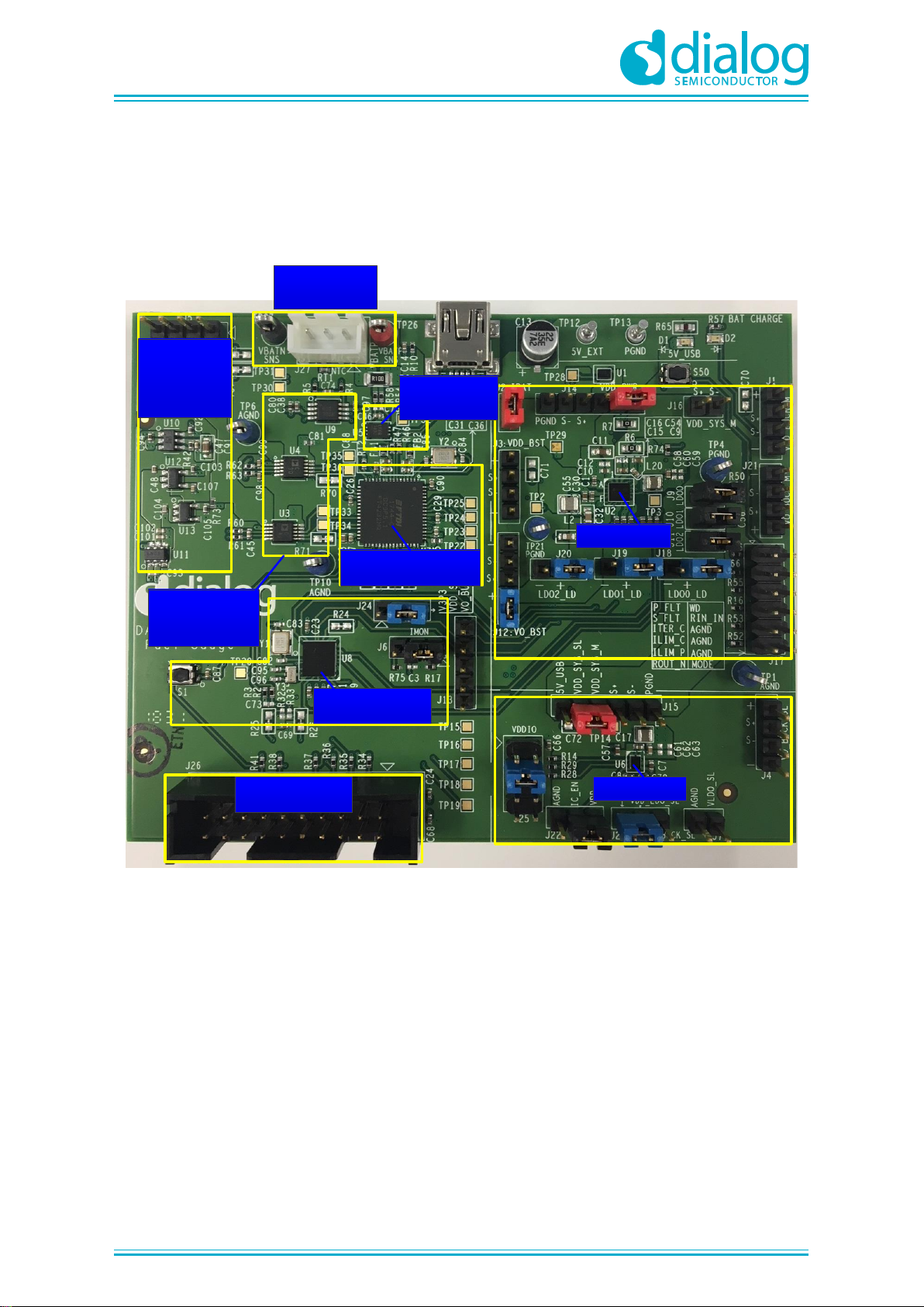
The whole system is designed to demonstrate the charge and discharge of a single lithium-polymer
battery, and the SOC (state-of-charge) prediction via fuel gauging. It also enables customer to do
independent evaluation on both DA9070 and DA9231 ICs. Figure 1 shows the top view of DA9070
Fuel gauge EVK board and highlights the function of each section.
DA9070(U2)
DA9231(U6)
USB to UART, SPI
(U7)
STM32L151(U8)
JTAG 20 pin
Connector (J26)
On-Board
+5V, +3.3V,
+2.5V, +1.8V
Regulators
Battery Profile
Circuitry
Battery
Connector
Ref Fuel
Gauge IC (U5)
Figure 1: DA9070 Fuel Gauge EVK Board Top View
Key Features
- Single USB connector supports both charging power and communication with PC
- Support STM32L151 MCU firmware update through JTAG 20 pin connector
- Two configurable modes through jumper: Chip evaluation mode; Battery Profile Mode including
Fuel Gauge Performance Test
- Supports register read/write in chip evaluation mode with Dialog's SmartCanvas GUI
- Supports battery characterization with real-time voltage and charge/discharge current measurement
which can be monitored with Dialog's Power Profile Manager (PPM) on PC
- Supports on-board customized load-profile programming
- Supports a performance comparison between Dialog's low-power software fuel gauge solution and
a reference Coulomb-counter based fuel gauge IC
Page 6
UM-PM-039
DA9070 / DA9231 Fuel Gauge Development Kit
NDA Confidential
User Manual
Revision 2.1
28-Oct-2018
6 of 18
© 2018 Dialog Semiconductor
System Diagram
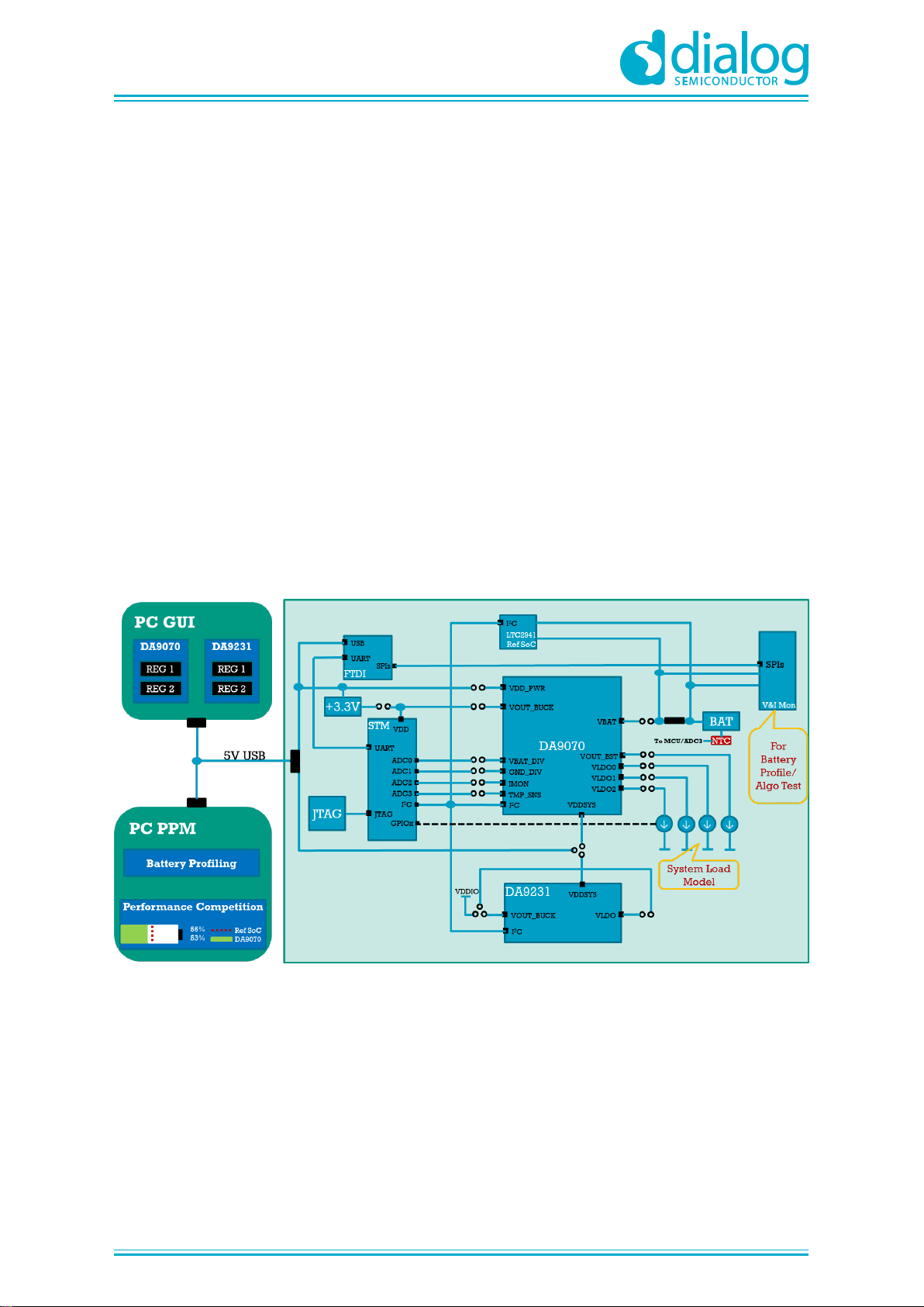
Figure 2 shows the DA9070 fuel gauge EVK system diagram. The whole system includes the
following major portions:
-DA9070: Dialog nano-power battery charge management PMIC with Fuel Gauge
-DA9231: Dialog nano-power PMIC
-STM32L151 MCU: For implementing fuel gauge SOC algorithm
-FDTI: Communication interface-bridge between USB and UART, SPI ports
-JTAG: Communication port for STM32L151 MCU firmware update
-LTC2941: Reference Coulomb-count based fuel gauge IC
-Battery V&I Monitor: Circuitry to monitor battery voltage & current in real-time. For battery profiling
-System Load Model: A set of on-board resistors with ON/OFF control issued by MCU to mimic
various load patterns in real applications
-PC GUI: Software on PC. For chip evaluation. Both registers of DA9070 and DA9231 can be read or
written through GUI
-PC PPM: Software on PC. For battery profiling and fuel gauge performance test
-BAT: Single lithium-poly battery. Support up to 500mAh
Figure 2: DA9070 Fuel Gauge EVK System Diagram
Page 7
UM-PM-039
DA9070 / DA9231 Fuel Gauge Development Kit
NDA Confidential
User Manual
Revision 2.1
28-Oct-2018
7 of 18
© 2018 Dialog Semiconductor
Chip Evaluation Mode
DA9070 Fuel gauge EVK is able to be configured to perform chip evaluations with or without battery.
For example, DA9070 or DA9231 can be evaluated for current consumption, efficiency, load/line
regulation, load/line transient etc. without battery; DA9070 can also be evaluated for sequence,
system load transient while the battery being plugged-in.
Evaluation Mode Basic Set-up
It is recommended to follow the following steps while setting up the chip evaluation mode.
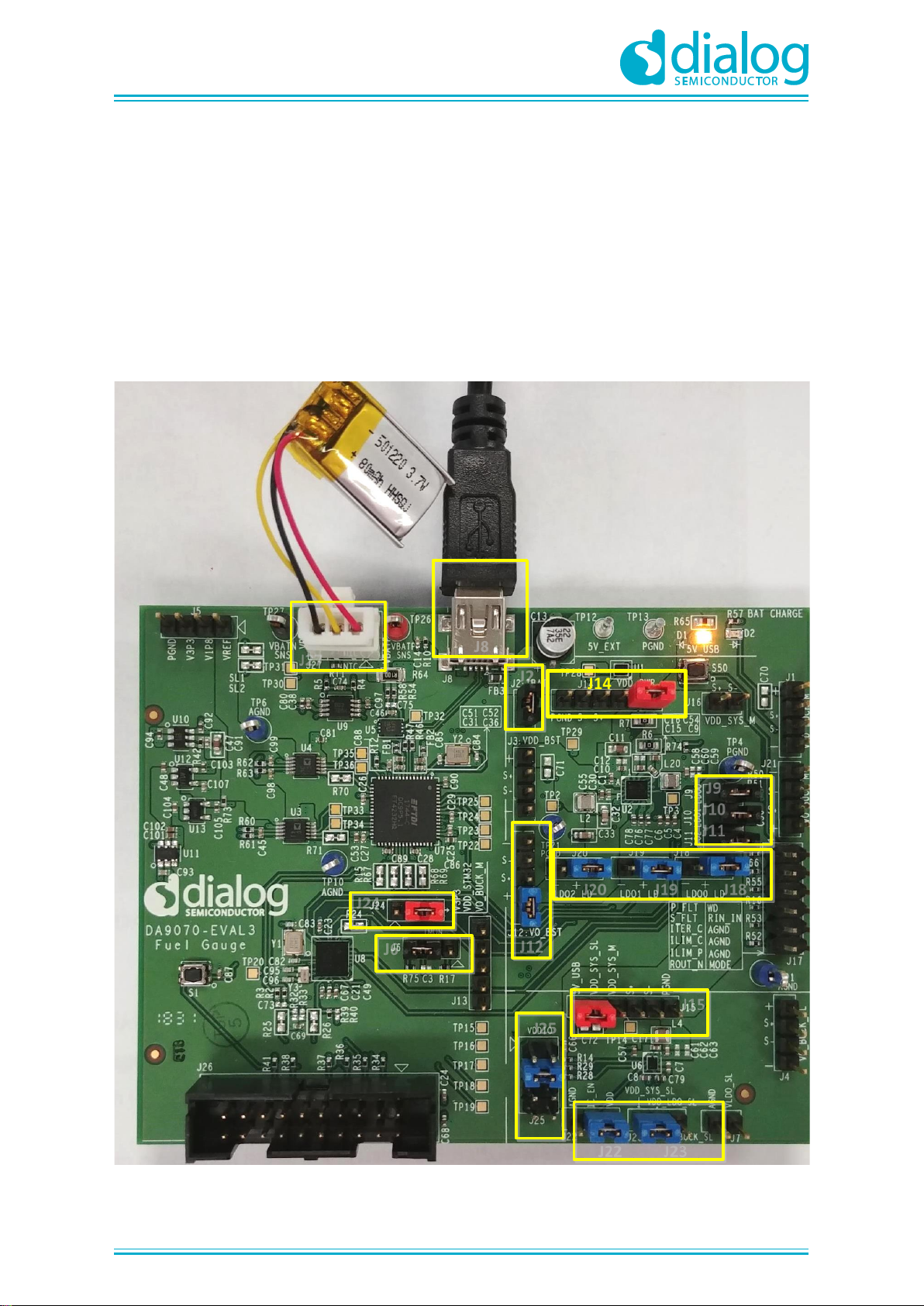
- Install jumpers as shown in Figure 3.
J14
EVALUATION
MODE
J9
J10
J11
J20 J19 J18
J12
J2
J15
J25
J22 J23
J24
J6
J27
J8
Figure 3: Basic Jumper Settings for Evaluation Mode
Page 8
UM-PM-039
DA9070 / DA9231 Fuel Gauge Development Kit
NDA Confidential
User Manual
Revision 2.1
28-Oct-2018
8 of 18
© 2018 Dialog Semiconductor
- The boxed jumpers must be installed in designated positions in order to evaluate both DA9070 and
DA9231. If only evaluate DA9070, change J22 jumper to IC_EN=AGND so DA9231 is disabled; If
only evaluate DA9231, remove J14 jumper so DA9070 is disabled.
- Connect the battery to J27. The positive terminal is labeled VBAT_P, adjacent to the red test point
TP26
- Plug in a USB cable into J8 connector. Connect the USB cable to either a traveler adapter or a PC.
The Yellow LED light is ON which means the EVK board is powered. By default, both DA9070 and
DA9231 are OTP programmed to start up automatically as soon as the EVK board is powered.
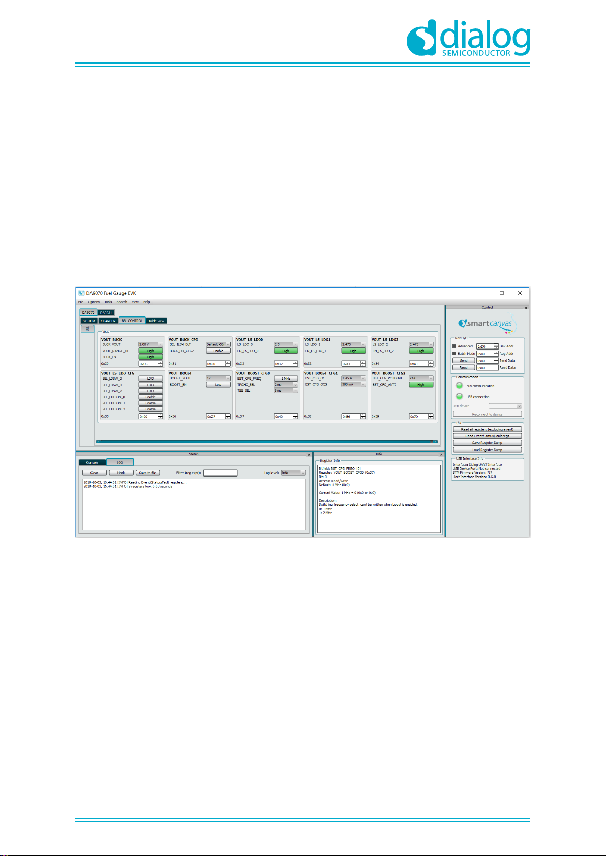
- If the USB cable is connected to a PC, open the "DA9070 Fuel Gauge EVK" GUI that was installed
on the PC. Start to configure device registers as well as read device status using GUI, as shown in
Figure 4.
Figure 4: GUI for DA9070 Fuel Gauge EVK
Page 9
UM-PM-039
DA9070 / DA9231 Fuel Gauge Development Kit
NDA Confidential
User Manual
Revision 2.1
28-Oct-2018
9 of 18
© 2018 Dialog Semiconductor
DA9070 Evaluation
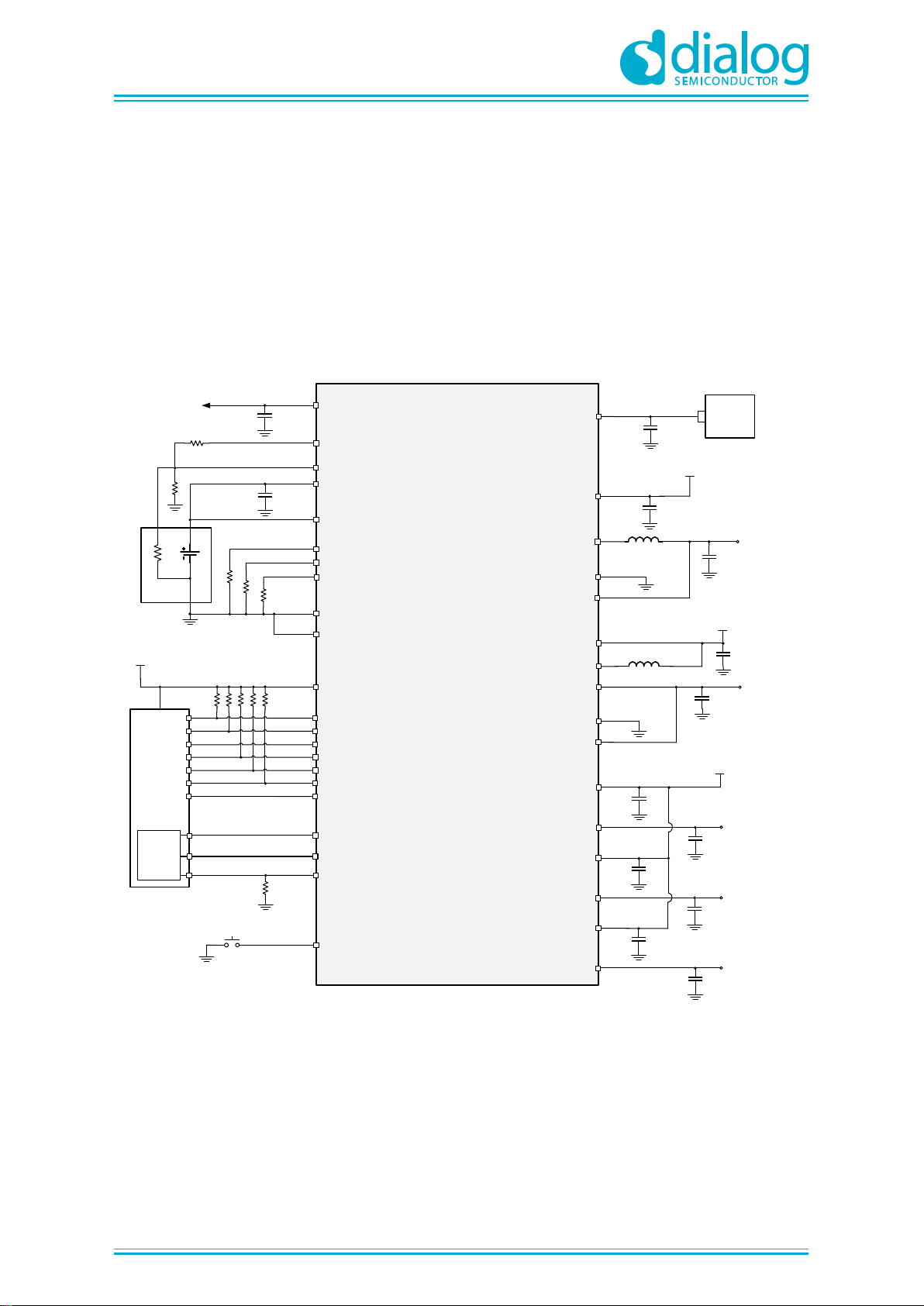
The typical application diagram of DA9070 is shown in Figure 5.
DA9070 includes a Buck regulator, a Boost Regulator, 3x LDO/LDSW, and a linear battery charger.
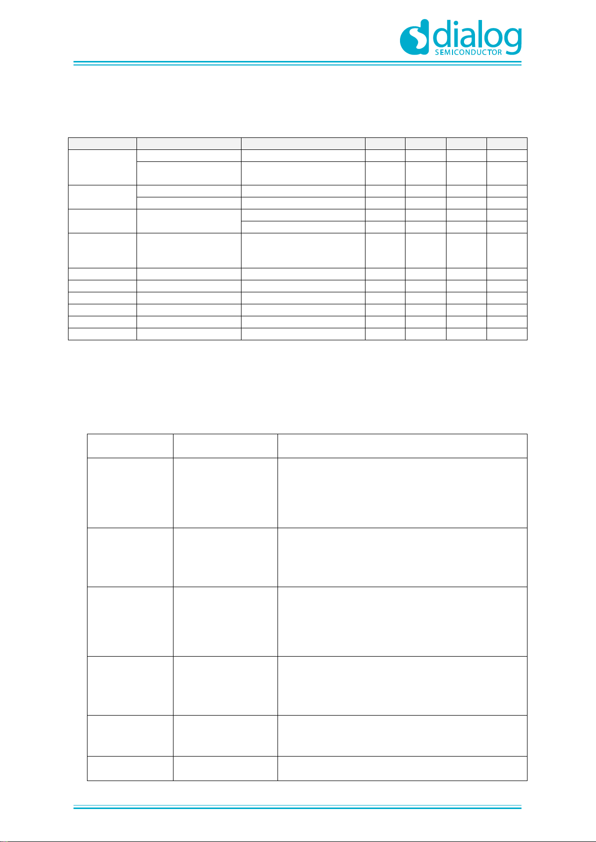
On DA9070 Fuel gauge EVK, each regulator can be evaluated individually. It is recommended to
follow the operation conditions as shown in Table 1 to avoid any damage to the EVK board. For test
and measurement set-up, please refer to Table 2 for descriptions of connectors on the EVK board.
DA9070
VBAT_SNS
GND
TEMP_SNS
ILIM_PWR
ILIM_CHG
ITER_CHG
NTC
VBAT
AGND
VDD_PWR
1.0µF
USB
VDD_SYS
Vdd_sys
4.7µF
VTEMP
PGND_BST
SW_BST
FB_BST
VOUT_BST
VDD_BST
Vdd_sys
Vo_boost
4.5V – 18V
MODE
PWR_FLT
SYS_FLT
SDA
SCL
ROUT_N
WD
MCU
VDDIO
VBAT_DIV
GND_DIV
IMON
ADC
(Fuel
Gauge)
RIN_N
PUSHBUTTON RESET
PGND_BUCK
FB_BUCK
SW_BUCK
Vo_buck
0.6V – 2.1V
300mA
VDD_BUCK
Vdd_sys
VLDO1
0.8V – 3.3V
150mA
VLDO2
0.8V – 3.3V
150mA
VLDO0
VDD_LDO0
VLDO0
0.8V – 3.15V
150mA
Vdd_sys
VLDO1
VDD_LDO1
VLDO2
VDD_LDO2
Vo buck
BATTERY
PACK
Figure 5: DA9070 Typical Application Diagram
Page 10
UM-PM-039
DA9070 / DA9231 Fuel Gauge Development Kit
NDA Confidential
User Manual
Revision 2.1
28-Oct-2018
10 of 18
© 2018 Dialog Semiconductor
Recommended Operating Conditions
Table 1: Recommended Operation Conditions
Parameter
Description
Conditions
Min
Typ
Max
Unit
VDD_PWR
VDD_PWR voltage
Including OVP range
3.6 5 20
V
VDD_PWR
operating voltage
3.6 5 5.5
V
VBAT
Battery voltage
VDD_PWR supplied
0
3.7
4.7 V Battery voltage
VDD_PWR not supplied
2.8
3.7
4.7
V
VDD_LDO
VDD_LDO voltage
Load switch mode
0.8 5.5 V LDO mode
1.8 5.5
V
VDDIO
IO voltage
VDDIO < VDD_PWR or
VBAT, whichever is
greater
1.4
1.8
3.3
V
I_PWR
VDD_PWR current
500
mA
I_BAT
Battery discharge
800
mA
I_SYS
VDD_SYS current
800
mA
I_LDO
LDO output current
150
mA
I_BUCK
Buck output current
300
mA
I_BOOST
Boost output current
12Vout, 2.7VBAT
100
mA
Connectors for DA9070 Evaluation
Table 2: DA9070 Input and Output Connectors
Connectors
Pin Names
Descriptions
J1
(VDD_BUCK_M)
+/ S+/ S-/ -
+ and - are terminals for connecting an external load
to the DA9070 VDD_SYS; S+ and S- are kelvin
sense points for DA9070 Buck input. For input
voltage measurement during efficiency test, S+ and
S- should connect to multi-meter for better accuracy.
J2
(IBAT)
Install J2 jumper will connect the VBAT pin of
DA9070 to battery positive terminal VBAT_P through
current sense shunt resistor. It also enables battery
current monitoring using external current probe.
J3
(VDD_BST)
+/ S+/ S-/ -
+ and - are terminals for connecting external power
supply to the Boost input; S+ and S- are kelvin sense
points for the Boost input. For input voltage
measurement during efficiency test, S+ and S- should
connect to multi-meter for better accuracy.
J6
(IMON)
Install J6 jumper will connect the IMON pin of
DA9070 to STM32L151(U8) ADC input. It also
enables IMON current measurement using external
multi-meter. Position 2-3 should be used.
J9
(LDO_0)
VDD_LDO0/
VDD_SYS_M
Install J9 jumper will connect LDO_0 input
(VDD_LDO0) to VDD_SYS_M of DA9070.
J10
VDD_LDO1/
Install J10 jumper will connect LDO_1 input
Page 11

UM-PM-039
DA9070 / DA9231 Fuel Gauge Development Kit
NDA Confidential
User Manual
Revision 2.1
28-Oct-2018
11 of 18
© 2018 Dialog Semiconductor
(LDO_1)
VDD_SYS_M
(VDD_LDO1) to VDD_SYS_M of DA9070.
J11
(LDO_2)
VDD_LDO2/
VDD_SYS_M
Install J11 jumper will connect LDO_2 input
(VDD_LDO2) to VDD_SYS_M of DA9070.
J12
(VO_BST)
BST_LD/ +/ S+/ S-/ -
+ and - are terminals for connecting external load to
the Boost output; When BST_LD (pin 1) is short to +
pin on J12, the on-board load resistor will be used as
the Boost output load. S+ and S- are kelvin sense
points for the Boost output. For output voltage
measurement during efficiency test, S+ and S- should
connect to multi-meter for better accuracy.
J13
VBAT_DIV/
GND_DIV/ I_MON/
TMP_SNS/ AGND
Sense points. For probe only.
J14
SW_BYPASS/
VDD_PWR/
SW_USE/ S+/ S-/
PGND
DA9070 power input (VDD_PWR) supply selection
and voltage sense. VDD_PWR can directly connect
to the 5V_USB rail by shorting J14 pin-1 to pin-2;
VDD_PWR can also connect to the 5V_USB rail
though load switch U1 by shorting J14 pin-2 to pin-3.
The load switch is controlled by the MCU during
battery profiling. For evaluation use jumper positions
1 and 2. J14-S+ and J14-S- pins are kelvin sense
points of DA9070 input VDD_PWR.
J16
(VDD_SYS_M)
S+/ S-
S+ and S- are kelvin sense points for DA9070
VDD_SYS.
J17
P_FLT, WD, S_FLT,
RIN_N, ITER_C,
AGND, ILIM_C,
AGND, ILIM_P,
AGND, ROUT_N,
MODE
Sense points. For probe only.
J18
(LDO0_LD)
LDO0_LD/ +/ -
+ and - are terminals for connecting an external load
to DA9070 LDO0 output; When pin-1 is shorted to the
+ pin on J18, the on-board load resistor will be used
as the LDO0 output load.
J19
(LDO1_LD)
LDO1_LD/ +/ -
+ and - are terminals for connecting external load to
DA9070 LDO1 output; When pin-1 is shorted to + pin
on J19, the on-board load resistor will be used as the
LDO1 output load.
J20
(LDO2_LD)
LDO2_LD/ +/ -
+ and - are terminals for connecting external load to
DA9070 LDO2 output; When pin-1 is shorted to + pin
on J20, the on-board load resistor will be used as the
LDO2 output load.
J21
(VO_BUCK_M)
+/ S+/ S-/ -
+ and - are terminals for connecting an external load
to DA9070 Buck output; S+ and S- are kelvin sense
points for DA9070 Buck output. For output voltage
measurement during efficiency test, S+ and S- should
connect to multi-meter for better accuracy.
Page 12
UM-PM-039
DA9070 / DA9231 Fuel Gauge Development Kit
NDA Confidential
User Manual
Revision 2.1
28-Oct-2018
12 of 18
© 2018 Dialog Semiconductor
GUI Features
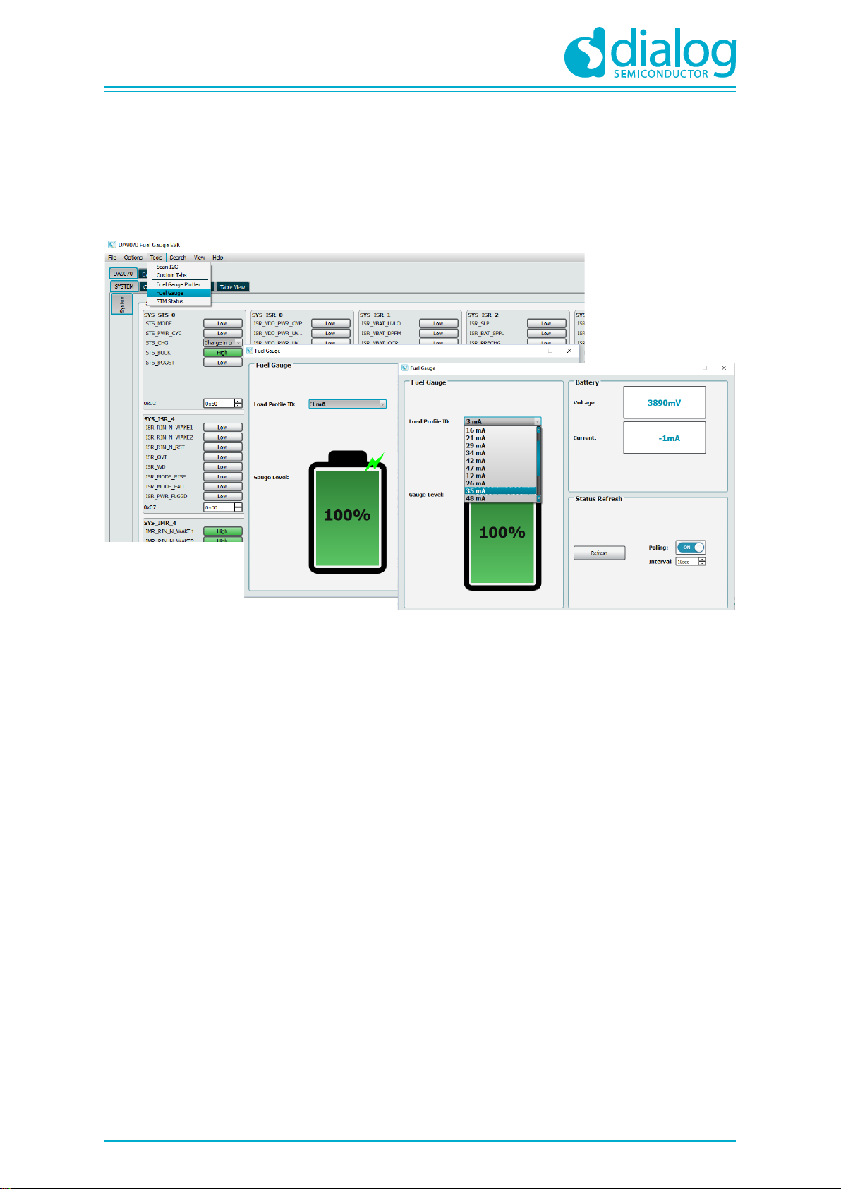
All DA9070 and DA9231 registers are accessible via the DA9070 Fuel Gauge EVK GUI.
The GUI also includes a fuel gauge function and on-board load control. These are shown in Figure 6.
Figure 6: Fuel Gauge and Load Profile Window
Note that the load values in the pull-down menu are based on the default resistor values in Table 3.
The minimum value of 3mA is the MCU's typical standby current.
The fuel gauge displays the real time battery voltage, discharge current, and State-of-Charge based
on the battery profile stored in the MCU. Be sure to update this profile if a different battery is used.
The fuel gauge will display the correct state of charge regardless of whether the on-board or external
loads are used. Charge current is not displayed and can be assumed to be the set charge current;
either set by the MCU at the pre-loaded value or by I2C command through the GUI.
The DA9070 fuel gauge outputs (IMON and VBAT_DIV) are directly controlled by the MCU. These
registers should not be controlled by the user.
Charging and Discharging
Battery charging is enabled by default. To stop battery charging, simply remove the jumper at J14.
This will remove VDD_PWR from the DA9070 and is the only method recognized by the MCU and
fuel gauge. Charging can also be enabled and disabled using I2C command or with the MODE pin.
When the battery is fully charged, the DA9070 will stop charging and restart only when the battery
voltage has dropped to the re-charge threshold.
Applying external loads to LDO and Boost outputs
For the three LDO rails as well as the Boost rail in DA9070, the DA9070 Fuel gauge EVK has the
flexibility to use either on-board load resistors or connect to external loads.
If on-board load resistors are used, jumpers need to be installed on LDO0/1/2_LD and VO_BST
connectors, as shown in Figure 3. The default load resistor values are shown in Table 3. The load
current for each rail will be determined by the programmed output voltage divided by the fixed load
resistor values. The total load can be controlled from the GUI Fuel Gauge window.
Page 13
UM-PM-039
DA9070 / DA9231 Fuel Gauge Development Kit
NDA Confidential
User Manual
Revision 2.1
28-Oct-2018
13 of 18
© 2018 Dialog Semiconductor
Table 3: Default Load Resistor Values
Designator
Description
Value
R72
Load resistor for LDO0 rail
30.9Ω, 1/2W
R9
Load resistor for LDO1 rail
62Ω, 1/4W
R11
Load resistor for LDO2 rail
154Ω, 1/8W
R8
Load resistor for Boost rail
3.3kΩ, 1/8W
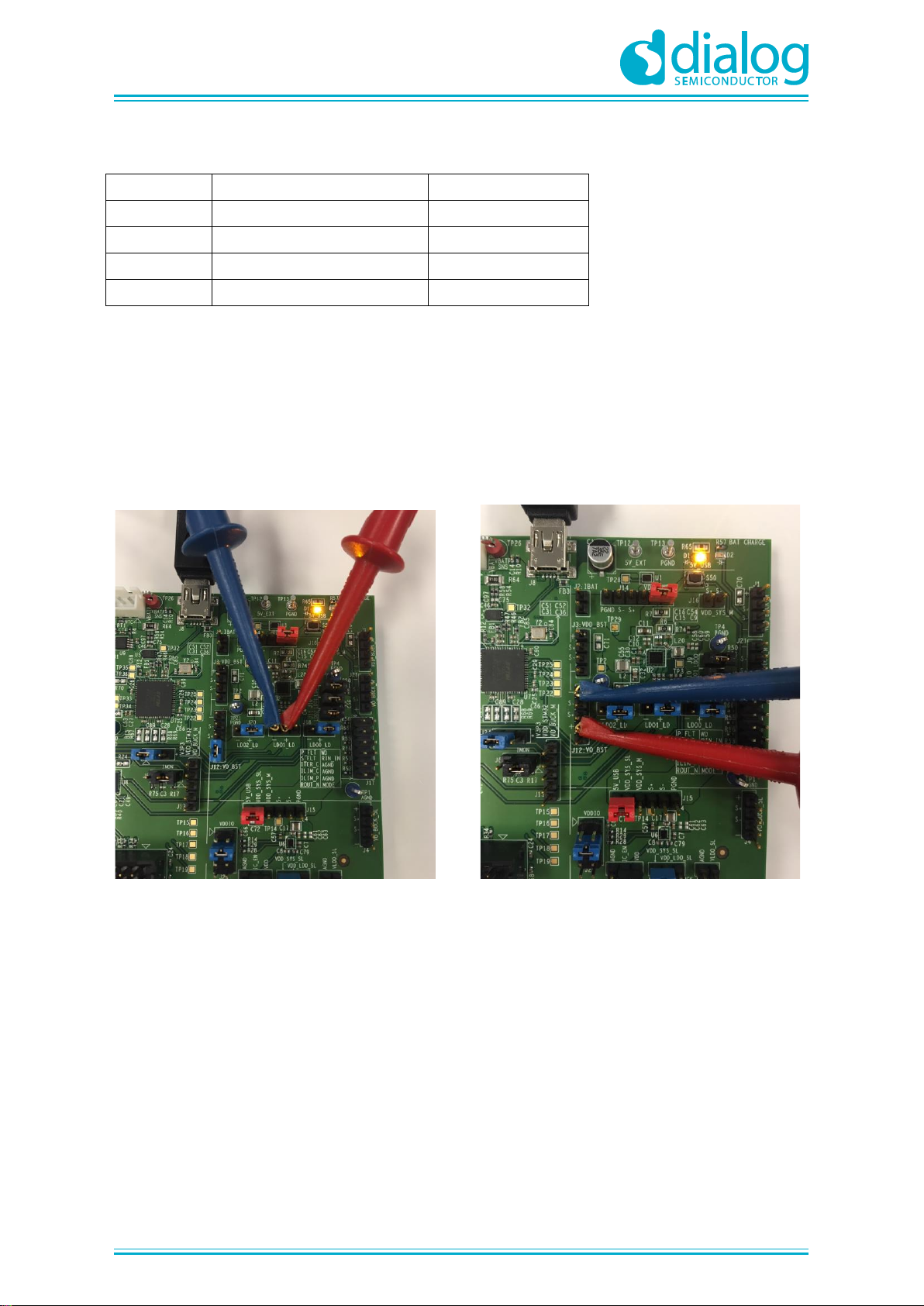
If an external load needs to be applied to any rail, first remove the jumper previously installed on
LDO0/1/2_LD or VO_BST connector. Then apply the external load between '+' and '-' terminals of
LDO0/1/2_LD or VO_BST connector, as shown in Figure 7.
Make sure the load current always flows out of '+' terminal and flows into '-' terminal on the
connectors.
Figure 7: Applying External Loads
LDO1 output Boost output
Page 14
UM-PM-039
DA9070 / DA9231 Fuel Gauge Development Kit
NDA Confidential
User Manual
Revision 2.1
28-Oct-2018
14 of 18
© 2018 Dialog Semiconductor
DA9231 Evaluation
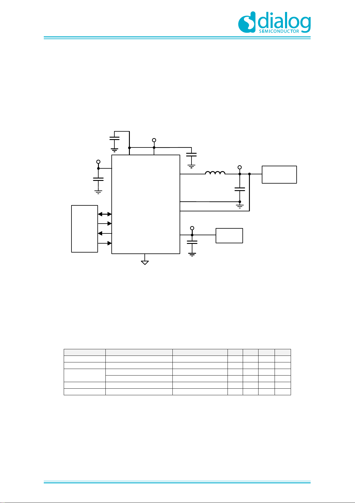
The typical application diagram of DA9231 is shown in Figure 8.
DA9231 includes a Buck regulator and an LDO. On the DA9070 Fuel gauge EVK, both the Buck and
LDO regulators can be evaluated individually. It is recommended to follow the operation conditions
as shown in Table 4 to avoid any damage to the EVK board. For test and measurement set-up,
please refer to Table 5 for descriptions of connectors on the EVK board.
DA9231
SW
VBUCK_SNS
PGND
VDD_SYSVDD
VDD_LDO
VLDO
SDA
SCL
GPO
GND
IC_EN
HOST
Buck Vout
Buck Vin
2.2 µH
10 µF
2.2 µF
Sensors
MCU/
System I/O
4.7 µF
1 µF
1 µF
LDO Vin
LDO Vout
Figure 8: DA9231 Typical Application Diagram
Recommended Operating Conditions
Table 4: Recommended Operation Conditions
Parameter
Description
Conditions
Min
Typ
Max
Unit
VDD
Analog Input
VDD= VDD_SYS
2.5 5.5 V VDD_SYS
Power Input
VDD= VDD_SYS
2.5 5.5
V
VDD_LDO
LDO mode
1.8 5.5 V Load Switch mode
0.8 5.5 V I_BUCK
Buck Output Current
300
mA
I_LDO
LDO Output Current
100
mA
Page 15

UM-PM-039
DA9070 / DA9231 Fuel Gauge Development Kit
NDA Confidential
User Manual
Revision 2.1
28-Oct-2018
15 of 18
© 2018 Dialog Semiconductor
Connectors for DA9231 Evaluation
Table 5: DA9231 Input and Output Connectors
Connectors
Pin Names
Descriptions
J4
(VO_BUCK_SL)
+/ S+/ S-/ -
+ and - are terminals for connecting external load to
DA9231 Buck output; S+ and S- are kelvin sense
points for DA9231 Buck output.
J7
VLDO_SL/ AGND
Terminals for connecting external load to DA9231
LDO output.
J15
5V_USB/
VDD_SYS_SL/
VDD_SYS_M/ S+/ S-/
PGND
DA9231 Input supply selection and voltage sense.
DA9231 input terminal (VDD_SYS_SL) can be
selected from 5V_USB or VDD_SYS_M of DA9070.
S+ and S- are kelvin sense points for DA9231 Buck
input.
J22
VDD/ IC_EN/ AGND
Set IC_EN to VDD to automatically start the
DA9231 when VDD is applied. Set IC_EN to AGND
to completely disables the DA9231, including I2C
communication.
J23
VDD_SYS_SL/
VDD_LDO_SL/
VO_BUCK_SL
LDO input supply selection. LDO input terminal
VDD_LDO_SL can be selected from either DA9231
input VDD_SYS_SL or DA9231 Buck output
VO_BUCK_SL.
J25
VO_BUCK_SL/ VDDIO
V2P5/ VDDIO
VLDO_SL/ VDDIO
VO_BUCK_M/ VDDIO
VDDIO voltage selection.
VDDIO can be connected from 4 options by
installing a jumper between VDDIO pin and the pin
next to its left: DA9070 Buck, DA9231 Buck,
DA9231 LDO, or independent 2.5V supply.
For evaluation purposes, the 2.5V supply position is
recommended to provide communications
regardless of which IC is enabled.
Page 16
UM-PM-039
DA9070 / DA9231 Fuel Gauge Development Kit
NDA Confidential
User Manual
Revision 2.1
28-Oct-2018
16 of 18
© 2018 Dialog Semiconductor
Battery Profile Mode
The DA9070 Fuel gauge EVK board can also be configured to perform battery characterization
(battery profile) and run a fuel gauge performance test. This is done using the Power Profile Manager
(PPM) software instead of the DA9070 Fuel Gauge GUI. The profile data for a specific battery is
generated by the PPM and loaded to the MCU. This profile is then used by the pre-loaded Dialog
algorithm for the SOC fuel gauge.
If the included 80mAh battery is used, battery profiling is not necessary; the MCU is pre-loaded with
both the fuel gauge algorithm and 80mAh battery profile.
Also pre-loaded to the MCU is the eval board calibration data. The calibration steps are described in
AN-SW-121 but do not need to be performed in most cases.
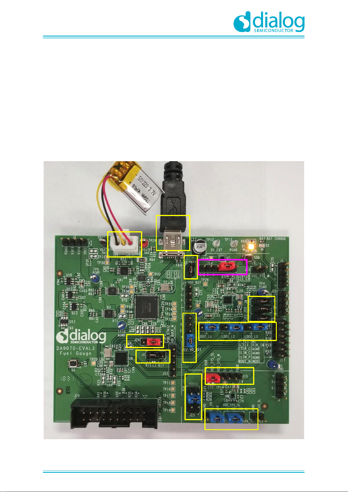
Figure 9 shows the jumper set-up of the DA9070 Fuel gauge board while battery profiling is running.
Note the jumper position of J14 in battery profile mode.
J14
J9
J10
J11
J20 J19 J18
J12
J2
J15
J25
J22
J23
J24
J6
J27
J8
BATTERY
PROFILE
MODE
Figure 9: Jumper Settings for Battery Profile Mode
Page 17
UM-PM-039
DA9070 / DA9231 Fuel Gauge Development Kit
NDA Confidential
User Manual
Revision 2.1
28-Oct-2018
17 of 18
© 2018 Dialog Semiconductor
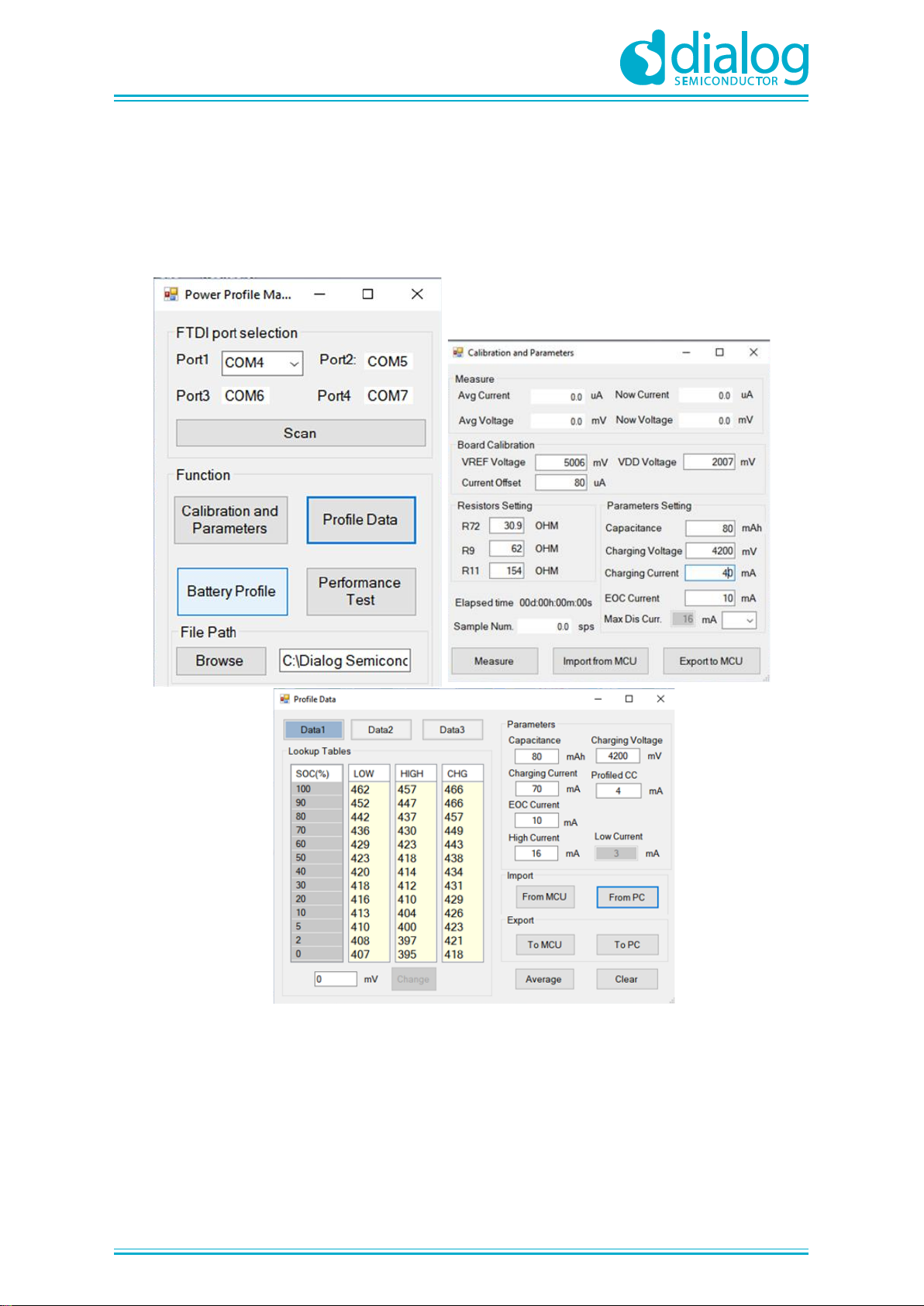
The entire battery profile process includes battery profiling, lookup table generation, and fuel gauge
performance test. Board calibration can also be performed using the PPM software.
The main PPM windows are shown in Figure 10.
Figure 10: PPM windows
Please refer to Application Note AN-SW-121 DA9070 Power Profile Manager and SOCF for step-bystep instructions on how to perform these tests.
Page 18
UM-PM-039
DA9070 / DA9231 Fuel Gauge Development Kit
NDA Confidential
User Manual
Revision 2.1
28-Oct-2018
18 of 18
© 2018 Dialog Semiconductor
Revision History
Revision
Date
Description
1.0
12-12-2017
Initial version
2.0
28-10-2018
Updated for EVAL 3
Disclaimer
Information in this document is believed to be accurate and reliable. However, Dialog Semiconductor does not give any representations or
warranties, expressed or implied, as to the accuracy or completeness of such information. Dialog Semiconductor furthermore takes no
responsibility whatsoever for the content in this document if provided by any information source outside of Dialog Semiconductor.
Dialog Semiconductor reserves the right to change without notice the information published in this document, including without limitation the
specification and the design of the related semiconductor products, software and applications.
Applications, software, and semiconductor products described in this document are for illustrative purposes only. Dialog Semiconductor makes
no representation or warranty that such applications, software and semiconductor products will be suitable for the specified use without further
testing or modification. Unless otherwise agreed in writing, such testing or modification is the sole responsibility of the customer and Dialog
Semiconductor excludes all liability in this respect.
Customer notes that nothing in this document may be construed as a license for customer to use the Dialog Semiconductor products, software
and applications referred to in this document. Such license must be separately sought by customer with Dialog Semiconductor.
All use of Dialog Semiconductor products, software and applications referred to in this document are subject to Dialog Semiconductor’s Standard
Terms and Conditions of Sale, available on the company website (www.dialog-semiconductor.com) unless otherwise stated.
Dialog and the Dialog logo are trademarks of Dialog Semiconductor plc or its subsidiaries. All other product or service names are the property of
their respective owners.
© 2018 Dialog Semiconductor. All rights reserved.
Contacting Dialog Semiconductor
United Kingdom (Headquarters)
Dialog Semiconductor (UK) LTD
Phone: +44 1793 757700
Germany
Dialog Semiconductor GmbH
Phone: +49 7021 805-0
The Netherlands
Dialog Semiconductor B.V.
Phone: +31 73 640 8822
North America
Dialog Semiconductor Inc.
Phone: +1 408 845 8500
Japan
Dialog Semiconductor K. K.
Phone: +81 3 5425 4567
Taiwan
Dialog Semiconductor Taiwan
Phone: +886 281 786 222
Singapore
Dialog Semiconductor Singapore
Phone: +65 64 8499 29
Hong Kong
Dialog Semiconductor Hong Kong
Phone: +852 3769 5200
Korea
Dialog Semiconductor Korea
Phone: +82 2 3469 8200
China (Shenzhen)
Dialog Semiconductor China
Phone: +86 755 2981 3669
China (Shanghai)
Dialog Semiconductor China
Phone: +86 21 5424 9058
Email:
Web site:
www.dialog-semiconductor.com
 Loading...