


Dialogic® SS7G2x Signaling Server
SGW Mode User Manual
www.dialogic.com

Copyright© 2005-2007 Dialogic Corporation. All Rights Reserved. You may not reproduce this document in
whole or in part without permission in writing from Dialogic Corporation.
All contents of this document are furnished for informational use only and are subject to change without notice and do not represent a commitment on the part
of Dialogic Corporation or its subsidiaries (“Dialogic”). Reasonable effort is made to ensure the accuracy of the information contained in the document.
However, Dialogic does not warrant the accuracy of this information and cannot accept responsibility for errors, inaccuracies or omissions that may be
contained in this document.
INFORMATION IN THIS DOCUMENT IS PROVIDED IN CONNECTION WITH DIALOGIC
BY ESTOPPEL OR OTHERWISE, TO ANY INTELLECTUAL PROPERTY RIGHTS IS GRANTED BY THIS DOCUMENT. EXCEPT AS PROVIDED
IN A SIGNED AGREEMENT BETWEEN YOU AND DIALOGIC, DIALOGIC ASSUMES NO LIABILITY WHATSOEVER, AND DIALOGIC
DISCLAIMS ANY EXPRESS OR IMPLIED WARRANTY, RELATING TO SALE AND/OR USE OF DIALOGIC PRODUCTS INCLUDING LIABILITY
OR WARRANTIES RELATING TO FITNESS FOR A PARTICULAR PURPOSE, MERCHANTABILITY, OR INFRINGEMENT OF ANY
INTELLECTUAL PROPERTY RIGHT OF A THIRD PARTY.
Dialogic products are not intended for use in medical, life saving, life sustaining, critical control or safety systems, or in nuclear facility applications.
It is possible that the use or implementation of any one of the concepts, applications, or ideas described in this document, in marketing collateral produced by
or on web pages maintained by Dialogic may infringe one or more patents or other intellectual property rights owned by third parties. Dialogic does not
provide any intellectual property licenses with the sale of Dialogic products other than a license to use such product in accordance with intellectual property
owned or validly licensed by Dialogic and no such licenses are provided except pursuant to a signed agreement with Dialogic. More detailed information
about such intellectual property is available from Dialogic’s legal department at 9800 Cavendish Blvd., Montreal, Quebec, Canada H4M 2V9. Dialogic
encourages all users of its products to procure all necessary intellectual property licenses required to implement any concepts or applications and
does not condone or encourage any intellectual property infringement and disclaims any responsibility related thereto. These intellectual property
licenses may differ from country to country and it is the responsibility of those who develop the concepts or applications to be aware of and comply
with different national license requirements.
Dialogic is a registered trademark of Dialogic Corporation. Dialogic's trademarks may be used publicly only with permission from Dialogic. Such permission
may only be granted by Dialogic’s legal department at 9800 Cavendish Blvd., 5th Floor, Montreal, Quebec, Canada H4M 2V9. Any authorized use of
Dialogic's trademarks will be subject to full respect of the trademark guidelines published by Dialogic from time to time and any use of Dialogic’s trademarks
requires proper acknowledgement.
Windows is a registered trademark of Microsoft Corporation in the United States and/or other countries. Other names of actual companies and products
mentioned herein are the trademarks of their respective owners.
®
PRODUCTS. NO LICENSE, EXPRESS OR IMPLIED,
Publication Date: September 2007
Document Number: 05-2304-004
2

Dialogic® SS7G2x Signaling Server SGW Mode User Manual Issue 4
Contents
1Overview.................................................................................................................. 8
1.1 General Description............................................................................................. 8
1.2 Related Information............................................................................................ 8
1.3 Applicability ....................................................................................................... 9
1.4 Hardware Overview....................... .. .. .................................................................. 9
1.4.1 Part Numbers.......................................................................................... 9
1.5 Connectivity....................................................................................................... 9
1.6 User Interface.................................................................................................... 9
1.7 Configuration and Program Storage......................................................................10
1.8 IP Security........................................................................................................10
1.9 Functional Summary ..........................................................................................10
1.9.1 Signaling...............................................................................................10
1.9.2 Configuration Model................................................................................11
1.9.3 Cross Connections ..................................................................................11
1.9.4 Monitoring .............................................................................................11
1.9.5 Remote Data Centres..............................................................................12
1.9.6 Alarm Log..............................................................................................12
1.9.7 M3UA Backhaul Operation........................................................................12
1.9.8 M2PA Longhaul Operation ........................................................................13
1.9.9 Default Routing ......................................................................................13
1.9.10 Resilience..............................................................................................13
2 Specification ............................................................................................................15
2.1 Hardware Specification........... .. ................................ .. ................................ .. ......15
2.2 System Capacity................................................................................................15
2.3 System Capabilities............................................................................................15
2.4 Signaling Capabilities (Per System) ......................................................................15
2.5 Physical Interfaces (Per Signaling Board) ..............................................................15
2.6 TDM Signaling Capabilities (Per Signaling Board)....................................................15
3 Installation and Initial Configuration .......................................................................16
3.1 Installation .......................................................................................................16
3.2 Connecting a VT100 Terminal ..............................................................................16
3.3 Software Download............................................................................................16
3.4 Initial Configuration ..... .. ............................... .. ................................ .. .................17
3.5 Configuration Procedure .....................................................................................19
4Operation.................................................................................................................20
4.1 General............................................................................................................20
4.2 Log On/Off Procedure.........................................................................................20
4.3 Command Character Set and Syntax ....................................................................21
4.4 Command Formats........................................................................ .....................21
4.5 Command Entry ............ ....................................................................................21
4.6 Dangerous Commands .......................................................................................22
4.7 Changing Configuration Data...............................................................................22
4.8 Command Responses...................... .. .. ...............................................................22
4.9 FTP Access........................................................................................................23
4.10 Backing Up System Software...............................................................................24
4.10.1 Software Backup to a Remote Data Centre.................................................24
4.11 Updating System Software..................................................................................24
4.11.1 Software Update from a Remote Data Centre .............................................24
4.11.2 Software Update from CD-ROM.................................................................24
4.11.3 Software Update from Startup..................................................................25
4.12 Backing Up Configuration Data ............................................................................25
4.12.1 Configuration Backup to Remote Data Centre .............................................25
4.13 Updating Configuration Data ...............................................................................26
3

Contents
4.13.1 Configuration Update from a Remote Data Centre .......................................26
4.13.2 Configuration Update from CD ROM...........................................................26
4.13.3 Configuration Update from Startup............................................................26
4.14 System Licenses................................................................................................27
4.14.1 Purchasing System License s........................................................... .. .. ......27
4.14.2 Installing System Licenses.......................................................................28
4.14.3 License Update from Remote Data Centre ..................................................28
4.14.4 License Update by FTP.............................................................................29
5 Parameter Definitions..............................................................................................30
5.1 Parameter Table ................................................................................................30
5.2 Remote Operations ............................................................................................37
5.3 Signaling Gateway Timers...................................................................................38
5.3.1 Signaling Gateway-Specific Timers............................................................38
5.3.2 MTP3-Specific Timers ..............................................................................38
5.3.3 SCTP-Specific Timers........ .. .. ................................ ................................ ...39
5.4 Board Types......................................................................................................39
6 Command Definitions...............................................................................................40
6.1 Command Groups........................................ .. .. ..................................................40
6.2 Command Notation....................... .. .. ................................ .. ...............................40
6.3 Command Attributes .................................. .. .. ................................ ....................40
6.4 Alarm Commands ........................................ ................................ ......................41
6.4.1 ALCLS – Alarm Class Set..........................................................................42
6.4.2 ALCLP – Alarm Class Print........................................................................42
6.4.3 ALFCP – Alarm Fault Code Print ................................................................43
6.4.4 ALLIP – Alarm List Print...........................................................................44
6.4.5 ALLOP – Alarm Log Print............................................. .............................45
6.4.6 ALREI – Alarm Reset Initiate ....................................................................46
6.4.7 ALTEI – Alarm Test Initiate.......................................................................46
6.4.8 ALTEE – Alarm Test End............................... ................................ .. ..........47
6.5 Configuration Commands....................................................................................48
6.5.1 CNBOI – Configuration Board Initiate.........................................................49
6.5.2 CNBOE – Configuration Board End.............................................................49
6.5.3 CNBOP – Configuration Board Print ...........................................................50
6.5.4 CNBUI – Configuration Back Up Initiate .......................... .. ... .. ....................50
6.5.5 CNMOI – Configuration Monitor Initiate......................................................51
6.5.6 CNMOE – Configuration Monitor End..........................................................51
6.5.7 CNMOP – Configuration Monitor Print....................................... .. ................52
6.5.8 CNPCI – Configuration PCM Initiate...........................................................52
6.5.9 CNPCC – Configuration PCM Change........................... .. .. .. .........................53
6.5.10 CNPCE – Configur ation PCM End ............. ................................ .. .. ..............53
6.5.11 CNPCP – Configuration PCM Print ..............................................................54
6.5.12 CNRDI – Configuration Remote Data Centre Initiate ....................................54
6.5.13 CNRDC – Configuration Remote Data Centre Change...................................55
6.5.14 CNRDE – Configuration Remote Data Centre End.........................................55
6.5.15 CNRDP – Configuration Remote Data Centre Print .......................................56
6.5.16 CNSWP – Configuration Software Print.......................................................56
6.5.17 CNSYS – Configuration System Set ...........................................................57
6.5.18 CNSYP – Configuration System Print..........................................................59
6.5.19 CNTDS – Configuration Time and Date Set.................................................60
6.5.20 CNTDP – Configuration Time And Date Print ...............................................60
6.5.21 CNTOS – Configuration Timeout Value Set..................................................61
6.5.22 CNTOP – Configuration Timeout Value Print................................................61
6.5.23 CNTSP – Configuration Timeslot Print ........................................................62
6.5.24 CNUPI – Configuration Update Initiate .......................................................63
6.5.25 CNXCI – Configuration Cross Conne ct Initiate.............................................64
6.5.26 CNXCE – Configuration Cross Connect End.................................................64
6.5.27 CNXCP – Configuration Cross Connect Print................................................65
6.6 SS7 Signaling Commands...................................................................................66
6.6.1 C7LSI – CCS SS7 Link Set Initiate.............................................................67
6.6.2 C7LSC – CCS SS7 Link Set Change ...........................................................68
6.6.3 C7LSE – CCS SS7 Link Set End.................................................................69
4

Dialogic® SS7G2x Signaling Server SGW Mode User Manual Issue 4
6.6.4 C7LSP – CCS SS7 Link Set Print................................................................69
6.6.5 C7RTI – CCS SS7 Route Initiate................................................................70
6.6.6 C7RTC – CCS SS7 Route Change...............................................................71
6.6.7 C7RTE – CCS SS7 Route End....................................................................72
6.6.8 C7RTP – CCS SS7 Route Print...................................................................72
6.6.9 C7SLI – CCS SS7 Signaling Link Initiate.....................................................73
6.6.10 C7SLC – CCS SS7 Signaling Link Change ...................................................74
6.6.11 C7SLE – CCS SS7 Signaling Link End.........................................................75
6.6.12 C7SLP – CCS SS7 Signaling Link Print........................................................75
6.7 IP Commands ...................................................................................................76
6.7.1 IPEPS – Set Ethernet Port Speed...............................................................77
6.7.2 IPEPP – Display Ethernet Port Speed .........................................................77
6.7.3 IPGWI – Internet Protocol Gateway Initiate ................................................78
6.7.4 IPGWE – Internet Protocol Gateway End ....................................................78
6.7.5 IPGWP – Internet Protocol Gateway Print...................................................79
6.8 MML Commands................................................................................................80
6.8.1 MMLOI – MML Log Off Initiate...................................................................81
6.8.2 MMLOP – MML Log Off Print......................................................................81
6.8.3 MMLOS – MML Log Off Set .......................................................................82
6.8.4 MMPTC – MML Port Change ......................................................................82
6.8.5 MMPTP – MML Port Print ..........................................................................83
6.9 Maintenance Commands.....................................................................................84
6.9.1 MNBLI – Maintenance Blocking Initiate ......................................................85
6.9.2 MNBLE – Maintenance Blocking End ..........................................................86
6.9.3 MNINI – Maintenance Inhibit Initiate .........................................................87
6.9.4 MNINE – Maintenance Inhibit End .............................................................87
6.9.5 MNRSI – Maintenance Restart System Initiate ............................................88
6.10 Measurement Commands....................................................................................89
6.10.1 MSC7P – Measurements SS7 Print.............................................................90
6.10.2 MSEPP – Measurement Ethernet Port Print .................................................92
6.10.3 MSPCP – Measurements PCM Print ............................................................94
6.10.4 MSSLP – Measurements SIGTRAN Link Print...............................................95
6.10.5 MSSYP – Measuremen ts System Print......................................... .. .............96
6.11 Remote Data Centre Commands ..........................................................................97
6.11.1 RDCRI – Remote Data Centre Continuous Record Initiate .............................98
6.11.2 RDCRC – Remote Data Centre Continuous Record Change......................... ...99
6.11.3 RDCRE – Remote Data Centre Continuous Record End ...............................100
6.11.4 RDCRP – Remote Data Centre Continuous Record Print ..............................100
6.11.5 RDPDI – Remote Data Centre Periodic Data Initiate...................................101
6.11.6 RDPDE – Remote Data Centre Periodic Data End.......................................101
6.11.7 RDPDP – Remote Data Centre Periodic Data Print......................................102
6.11.8 RDPRI – Remote Data Centre Periodic Report Initiate.................................103
6.11.9 RDPRC – Remote Data Centre Periodic Report Change ...............................104
6.11.10RDPRE – Remote Data Centre Periodic Report End.....................................104
6.11.11RDPRP – Remote Data Centre Periodic Report Print....................................105
6.12 Signaling Gateway Commands...........................................................................106
6.12.1 SGDPI – Signaling Gateway Destination Point Initiate ................................107
6.12.2 SGDPC – Signaling Gateway Destination Point Change...............................107
6.12.3 SGDPE – Signaling Gateway Destination Point End ....................................108
6.12.4 SGDPP – Signaling Gateway Destination Point Print...................................108
6.12.5 SGIRI – Signaling Gateway Incoming Route Initiate...................................109
6.12.6 SGIRC – Signaling Gateway Incoming Route Change ................................110
6.12.7 SGIRE – Signaling Gateway Incoming Route End.......................................110
6.12.8 SGIRP – Signaling Gateway Incoming Route Print......................................111
6.12.9 SGRKI – Signaling Gateway Routing Key Initiate.......................................112
6.12.10SGRKE – Signaling Gateway Routing Key End...........................................113
6.12.11SGRKP – Signaling Gateway Routing Key Print..........................................113
6.13 SIGTRAN Commands........................................................................................114
6.13.1 SNALI – SIGTRAN Application Server List Initiate ......................................115
6.13.2 SNALE – SIGTRAN Application Server List End........................... .. .. ...........115
6.13.3 SNALP – SIGTRAN Application Server List Print.........................................116
6.13.4 SNAPI – SIGTRAN Application Server Initiate............................................116
6.13.5 SNAPE – SIGTRAN Application Server End................................................117
6.13.6 SNAPP – SIGTRAN Application Server Print............................................... 117
6.13.7 SNNAI – SIGTRAN Network Appearance Initiate.................................. .. .. ..118
5

Contents
6.13.8 SNNAE – SIGTRAN Network Appearance End............................................118
6.13.9 SNNAP – SIGTRAN Network Appearance Print...........................................119
6.13.10 SNSLI – SIGTRAN Signaling Link Initiate..................................................120
6.13.11 SNSLC – SIGTRAN Signaling Link Change.................................................121
6.13.12 SNSLE – SIGTRAN Signaling Link End......................................................121
6.13.13SNSLP – SIGTRAN Signaling Link Print.....................................................122
6.14 Status Commands ...........................................................................................123
6.14.1 STALP – Status Alarm Print ....................................................................124
6.14.2 STAPP – Status Application Server Print ..................................... .. .. ..........125
6.14.3 STBOP – Status Board Print....................................................................126
6.14.4 STCRP – Status C7 Route Print ...............................................................127
6.14.5 STC7P – Status C7 Link Print..................................................................128
6.14.6 STEPP – Status Ethernet Port Print..........................................................129
6.14.7 STIPP – Status IP Print ..........................................................................130
6.14.8 STPCP – Status PCM Print ......................................................................131
6.14.9 STRDP – Status Remote Data Centre Print ...............................................132
6.14.10STSLP – Status SIGTRAN Link Print.............................. ...........................133
6.14.11STSYP – Status System Print..................................................................134
7 Configuration Overview .........................................................................................135
7.1 System, Hardware and Signaling Configuration....................................................135
7.1.1 System Configuration............................................................................135
7.1.2 Boards and PCMs........................................................................ ..........136
7.2 Signaling Configuration.....................................................................................136
7.2.1 SS7 Configuration.................................................................................136
7.2.2 M3UA Configuration ..............................................................................138
7.3 Routing Configuration.......................................................................................139
7.4 Management and Operations.............................................................................141
7.5 Default Routing ...............................................................................................141
7.5.1 Configuring Default Routing ...................................................................141
7.6 Resilience .......................................................................................................142
7.6.1 IP Port Bonding ....................................................................................142
7.6.2 Dual Resilient Operation ........................................................................143
7.6.3 Multihoming.........................................................................................145
8 Alarm Fault Code Listing ........................................................................................146
9 Remote Data Centre Operation...............................................................................151
9.1 Local Data Centres...........................................................................................151
9.2 Continuous Records .........................................................................................151
9.3 Periodic Reporting............................................................................................151
9.3.1 C7 Link Traffic Measurements.................................................................151
9.3.2 PCM Traffic Measurements ........................................ .............................151
9.3.3 SIGTRAN Link Traffic Measurements........................................................152
9.3.4 Ethernet Port Traffic Measurements.........................................................152
9.3.5 System Measurements ..........................................................................152
9.4 RDC File Formats......................................... .. .. ................................ ................152
9.4.1 Alarm Record File Format...................................................................... .152
9.4.2 Ethernet Port Measurements File Format ..................................................153
9.4.3 PCM Measurements File Format ..............................................................153
9.4.4 SS7 Link Measurements File Format ........................................................154
9.4.5 SIGTRAN Link Measurements File Format.................................................155
9.4.6 System Measurements File Format..........................................................155
9.5 RDC Configuration and Usage.............................. .. .. ... ............................... .. .. ... .155
9.5.1 RDC Initialization........................................ ................................ .. ........155
9.5.2 Continuous Records ..............................................................................156
9.5.3 Periodic Reports....................................................................................156
9.5.4 Software Update...................................................................................157
9.5.5 Configuration Backup ............................................................................157
9.5.6 Configuration Update ............................................................................157
6

Dialogic® SS7G2x Signaling Server SGW Mode User Manual Issue 4
9.5.7 Software Option Installation...................................................................157
10 SS7G2x SNMP MIB.................................................................................................158
11 Worked Configuration Examples ............................................................................160
11.1 Backhaul Configuration............................................. ................................ .. .. ....160
11.2 M2PA Longhaul Configuration ............................................................................160
11.3 Dual Resilient Configuration ..............................................................................161
11.3.1 SG 1 Configuration................................................................................162
11.3.2 SG 2 Configuration................................................................................162
12 Command Summary...............................................................................................163
Glossary.................................................................................................................166
Index.....................................................................................................................168
Figures
1 M3UA Backhaul Configuration........................ .. ................................ .. .. .. .....................13
2 M2PA Longhaul Configur ation............................................................ .. .......................13
3 Dual Resilient Configuration.......................................................................................14
4 Multiple IP Networks..................... .. .. ................................ .. .. ................................ ..135
5 Physical Configuration.............................................................................................136
6 SS7 Signaling Example............................................................................................137
7 M2PA Example........................... ............................................................................138
8 M3UA Backhaul Example ....... .. .. .. ................................ .. ............................... ... ........139
9 Routing Configuration Example.................................................................................140
10 System Using Default Routing ..................................................................................142
11 Dual Resilient Operation..........................................................................................144
12 Example Back-Haul Co nfig uration ........................................... .. .. ... ...........................160
13 M2PA Longhaul Configuration.............................. ................................ .. .. .................161
14 Example Dual Resilient Configuration ........................................................................161
Tables
1 Command Rejection Responses ..................................................................................22
2 Parameter Definitions................................................................................................30
3 Remote Operation Types....................................... .. ................................ ...................37
4 Signaling Gateway Specific Timers..............................................................................38
5 MTP3 ITU Timers......................................................................................................38
6 MTP3 ANSI Timers....................................................................................................38
7 SCTP-Specific Timers................................................................................................39
8 Board Types.............................................................................................................39
9 Alarm Fault Codes ..................................................................................................146
Revision History
Date Part Number Issue Description of Changes
September 2007 05-2304-004 4 Updates for brand changes, web sites, and other minor corrections.
December 2005 05-2304-003 3
May 2005 05-2304-001 2 Supports the first production release.
March 2005 05-2304-001-01 1 Field Trial release.
Note: The latest released issue of this guide can be found at:
http://www.dialogic.com/support/helpweb/signaling
Updates to include support for resilient IP connectivity, additional
measurement and status commands (STSYP, MSSYP and MSEPP) and
other minor enhancements and corrections.
7

Chapter 1 Overview
Chapter 1: Overview
1.1 General Description
®
The Dialogic
SS7G21 and SS7G22 products," individually as "SS7G21" and "SS7G22," respectively, or individually or
interchangeably as "SS7G2x"), with the Dialogic® SS7SBG20SGW SGW Mode software license installed and
enabled, operate as SIGTRAN Signaling Gateways (hereinafter sometimes referred to as "Signaling
Gateway"). They provide an interface between SS7 and IP networks, allowing SS7 information to be carried
over IP to either IP resident signaling points and applications (for example, a soft switch) or to another
Signaling Gateway. IETF SIGTRAN protocols are used to ensure interoperability with third party equipment.
The Signaling Server may be purchased as one of two equipment types; SS7G21 and SS7G22. Each
equipment type uses the same chassis and operates with the same software, but uses different signaling
boards. See Section 1.4, “Hardware Overview” on page 9 for a fuller description of the Signaling Server
hardware.
The Signaling Gateway uses the SIGTRAN M3UA protocol to "backhaul" SS7 signaling messages to IP
resident Application Servers, removing the need for Application Hosts to have dedicated SS7 MTP services or
hardware. Application Servers using the Signalling Gateway may be part of a single point code or multiple
point codes.
The Signaling Gateway M3UA architecture uses open standards interfaces, providing flexibility , scalability and
resilience. It is easy to add or reconfigure M3UA Application Servers and Signaling Gateways to meet
demands for new services or increased capacity.
SS7G21 and SS7G22 Signaling Servers, (hereinafter sometimes referred to collectively as "the
The Signaling Gateway also supports SIGTRAN M2PA protocol to talk to other Point Codes over IP links,
rather than TDM. M2PA may be used to connect within the central office, or for longhaul links over IP.
The SIGTRAN Signaling Gateway (SGW) functionality is provided as a software option on the SS7G21 and
SS7G22 Signaling Servers. To enable this functionality, order and install the SS7SBG20SGW software
license. A unit with the SGW Mode license installed and enabled is referred to as a “Signaling Gateway”
throughout this manual.
When the software license is either not installed or deactivated, the SS7G21 and SS7G22 act as SS7
Signaling Interface Units (SIUs), providing an interface to SS7 networks for a number of distributed
application platforms via TCP/IP LAN. In this mode, the units implement the SS7 Message Transfer Part
(MTP) and a number of User Parts (ISUP, SCCP, TCAP, MAP, IS41 and INAP). See the SS7G2x SIU Mode User
Manual for a detailed description of this mode of operation.
The SS7G21 and SS7G22, when fitted with the DSC Mode software license, operate as a protocol converter.
It provides protocol interworking between any pair of telephony protocols for both network protocols and
access protocols. Description and use of the system acting as a protocol converter is outside the scope of this
manual. See the SS7G2x DSC Mode User Manual for a detailed description of this mode of operation.
The SS7G21 and SS7G22 are shipped without the SGW Mode Software License installed and therefore start
up initially as SS7 Signaling Interface Units (SIUs). The procedures for the purchase and installation of the
SGW and other software options are described in Section 4.14, “System Licenses” on page 27. The
procedures required to configure a unit for SGW operation as well as those for initial system configuration
are described in Chapter 3, “Installation and Initial Configuration”.
1.2 Related Information
®
This user manual, together with the Dialogic
SS7G21 and SS7G22 Hardware Manual forms the
documentation set for the SGW mode of operation of an SS7G2x. The Dialogic® SS7G21 and SS7G22
Hardware Manual addresses the hardware-specific aspects of the product including: hardware variants,
installation, specification, module replacement and a full description of the hardware modules. This user
manual describes the user interface together with all parameters and configuration commands.
The full title of the hardware manual is:
• Dialogic
®
SS7G21 and SS7G22 Signaling Servers Hardware Manual –
(05-2300-xxx)
8

®
Dialogic
SS7G2x Signaling Server SGW Mode User Manual Issue 4
The latest software and documentation supporting SS7G2x products is available on the web at
http://www.dialogic.com/support/helpweb/signaling.
The product data sheet is available at
http://www.dialogic.com/support/helpweb/signaling.
®
For more information on Dialogic
SS7 products and solutions, visit
http://www.dialogic.com/support/helpweb/signaling.
When used for M3UA backhaul operation, the Signaling Gateway may operate with an ASP operating either
an Dialogic M3UA Application Server or an Application Server provided by a third party vendor. See the
Dialogic
®
SS7 Protocols Programmer’s Manual for SIGTRAN Host Software for documentation on the
configuration and use of a Dialogic M3UA Application Server.
1.3 Applicability
This manual is applicable to SS7G2x units with software V3.02 and later installed. This manual is not
applicable when operating as a Signaling Interface Unit (SIU) or as a DSC Protocol Converter (DSC). See the
Dialogic
®
SS7G2x SIU Mode User Manual and the Dialogic® SS7G2x DSC Mode User Manual for descriptions
use of these modes of operation.
1.4 Hardware Overview
The Signaling Gateway may be purchased as one of two equipment types; SS7G21 and SS7G22. Each
equipment type uses the same chassis and operates with the same software, but differ in the type of preinstalled SS7 Signaling boards. This provides options in the numbers and types of links and ports available.
An SS7G21 may be purchased with one, two, or three SPCI2S boards (where each board provides four SS7
links, two T1/E1 interfaces and two V.11 serial ports per board) or one, two or three SPCI4 boards (where
each board provides four SS7 links and four T1/E1 interfaces per board).
An SS7G22 may be purchased with one, two or three SS7HDP boards (where each board provides 64 SS7
links and four T1/E1 interfaces per board) with a system maximum of 128 SS7 links.
When T1 or E1 is selected, the Signaling Gateway may be configured to pass the bearer channels from one
PCM port to another, effectively “dropping out” the signaling in line.
See Chapter 2, “Specification” for a full definition of the capabilities of the system.
1.4.1 Part Numbers
®
See the Dialogic
SS7G21 and SS7G22 Hardware Manual for a full list of the ordering codes and definitions
of all of the hardware variants of the two equipment types.
1.5 Connectivity
TDM SS7 signaling can interface to the Signaling Gateway using balanced 1544 kbit/sec (T1) balanced
connections in accordance with G.733 or 2048 kbit/sec (E1) connections in accordance with G.703. SS7
signaling can also be presented on a V.11 (56/64 kbit/sec) synchronous serial interface.
MP2A signaling used for communication between paired Signaling Gateways can be received at the conveter
using 4 x 1 Gbit/sec RJ45 Ethernet™ interfaces.
1.6 User Interface
The Signaling Gateway provides serial port and telnet connections for configuration and management. All
ports provide identical functionality and operate using text-based MML (Man Machine Language) commands
in accordance with CCITT recommendations.
The serial and telnet ports allow the user to configure the Signaling Gateway for operation and to carry out
subsequent modifications to the configuration. They allow the user to read the current status of the various
signaling entities and to view the current active alarms and a history of past alarm events.
9

Chapter 1 Overview
The Signaling Gateway provides SNMP V1 support to allow the reporting of alarms to an SNMP manager. See
Chapter 10, “SS7G2x SNMP MIB” for more information.
The Signaling Gateway has alarm indicators on the front panel and alarm relays for connection to an
integrated management system.
1.7 Configuration and Program Storage
All configuration data is stored on hard disk and is automatically recovered after system restart.
Configuration data may optionally be backed up to a remote computer, previously backed-up configurations
can be reloaded.
All operating software is stored on hard disk and is automatically initiated after system restart. The oper ating
software can be updated either by reading a new software release from CD ROM or by FTP transfer from a
remote computer. In both cases, software update is initiated by MML command. See Section 4.11, “Updating
System Software” on page 24 for details. Following a software update, the Signaling Gateway automatically
uses the saved configuration data so that there is no need to reenter the configuration parameters.
1.8 IP Security
The Signaling Gateway offers a number of security features to protect it from unwarranted access on its IP
interface. It is recommended that the user always enable the optional password protection on the
management interface port and on the FTP server port (if used).
For additional security, the Signaling Gateway is also equipped to support
Secure Shell (SSH).
Unused ports are disabled to increase security against unintentional or malicious interference.
Additional security may be gained by separating management and signaling IP traffic. This can be achieved
by configuring specific Ethernet ports for traffic and utilizing other Ethernet ports for system management.
It should be understood that while the Signaling Gateway has been designed with security in mind, it is
recommended that Signaling Gateway accessibility over IP is restricted to as small a network as possible. If
the unit is accessible by third parties, the use of a third-party firewall should be considered.
1.9 Functional Summary
The functional summary is described in the following topics:
telnet and FTP access using a
• Signaling
• Configuration Model
• Cross Connections
• Monitoring
• Remote Data Centres
• Alarm Log
• M3UA Backhaul Operation
• M2PA Longhaul Operation
• Dual Operation
• Default Routing
1.9.1 Signaling
The Signaling Gateway supports the Message Transfer Part (MTP) in accordance with ITU Recommendations
Q.700, Q.704 and Q.707 and ANSI operation in accordance with ANSI T1.111.
When a link set contains two or more signaling links, the Signaling Gateway supports load sharing and the
full changeover and changeback procedures in accordance with ITU-T Q.704.
10

®
Dialogic
SS7G2x Signaling Server SGW Mode User Manual Issue 4
The Signaling Gateway supports up to 128 TDM SS7 signaling links allowing the Signaling Gateway to
interface over TDM to a maximum of 64 other signaling points.
If required, each signaling link in a link set can be terminated on a separate signaling board providing
additional resilience.
The Signaling Gateway can have a presence in up to four separate IP subnets.
The Signaling Gateway supports up to 32 M2PA SS7 signaling links, allowing the Signaling Gateway to
interface over IP to a maximum of 32 other signaling points.
M2PA is supported in accordance with the IETF SS7 MTP2-User Peer-to-Peer Adaptation Layer specification.
SCTP is supported in accordance with IETF RFC 2960 and RFC 3309 Stream Control Transmission Protocol.
The Signaling Gateway supports communication with up to 200 Application Servers Processes (ASPs) for
backhaul operation over M3UA.
M3UA is supported in accordance with the IETF RFC 3332 SS7 MTP3 User Adaptation Layer.
1.9.2 Configuration Model
MTP data messages are considered to arrive at either an MTP3 link set or an M3UA SIGTRAN link. The link
set or M3UA SIGTRAN link identifies the network and SS7 format of the message. MTP3 link sets can exist
above a TDM MTP2 signaling link or a signaling link utilizing a M2PA SIGTRAN link for communication over IP.
The decision as to how to process the data message is performed by the incoming route. The incoming
route is identified by the network and domain (either MTP or IP) that a message arrives from.
The incoming route then determines whether the message requires further analysis of the data prior to
destination selection by looking up a routing key table or whether a destination can immediately be
selected.
If the Signaling Gateway determines that a routing key table be looked up, the data from the data message
is compared with routing keys in a routing key table. If a match is found, and the destination for that routing
key is in service, that destination is used. Otherwise, if the incoming route also has a destination associated
with it, that default destination is used. If no routing key table is associated with it, the default destination is
used.
A destination can route a data message to either an Application Server (AS) or to MTP (MTP over MTP2 or
MTP over M2PA). Selection of whether MTP or IP routing is used is determined by the availability of the data
messages point code in the MTP or IP domain and whether MTP or IP has priority.
If MTP routing is selected, the data message is sent out on an MTP SS7 route that matches the point code of
the data message. It is possible to configure MTP3 with a default route for use when it is undesirable to
preconfigure all routes that are used.
See Chapter 7, “Configuration Overview” for a more detailed configuration discussion and Chapter 11,
“Worked Configuration Examples” for some examples.
1.9.3 Cross Connections
The Signaling Gateway allows the user to set up cross connections (semi-permanent connections) between
an incoming timeslot on one PCM port and an outgoing timeslot on any PCM port. These connections can
either be simplex or duplex.
1.9.4 Monitoring
The Signaling Gateway allows the user to monitor TDM signaling links by dropping a copy of the signaling to
a spare PCM port. This allows for a protocol analyzer to be left connected to one PCM port and gives the user
the ability to control remotely which signaling links are monitored. Each monitored signaling link requires
two timeslots on the spare PCM port, one to monitor the send direction and the other for the receive
direction.
11

Chapter 1 Overview
1.9.5 Remote Data Centres
The Signaling Gateway supports the transfer of software updates, configuration files, alarm reports and
periodic measurements over Ethernet to/from a remote location, the Remote Data Centre (RDC).
Multiple RDCs can be configured by specifying an IP address and a user name and password for the Signaling
Gateway to use to “logon” to the RDC.
Data transfer to the RDC uses the File Transfer Protocol (FTP).
Measurement reports are made on a configurable periodic basis.
Optionally, since it can be configured as an FTP server, the Signaling Gateway itself can be configured to act
as an RDC, thus allowing RDC operation to be performed locally on the Signaling Gateway itself.
See Chapter 9, “Remote Data Centre Operation” for a more detailed description of the capabilities and
configuration of an RDC.
1.9.6 Alarm Log
®
The Dialogic
hardware or the operation of the protocols. Each alarm condition is assigned a severity/class (3 = Critical,
2 = Major , 1 = Minor) and a category and ID, which give more detail about the alarm. There are a number of
mechanisms described below, by which these conditions can be communicated to management systems, and
ultimately to the system operator (see Chapter 8, “ Alarm F ault Code Listing” for a full list of alarm t ypes, and
their reporting parameters):
• Active alarms are indicated on the front panel of the unit by three LEDs showing the severity; CRT, MJR
and MNR. See the Dialogic
these indicators.
SS7G2x product is able to detect a number of events or alarm conditions relating to either the
®
SS7G21 and SS7G22 Hardware Manual for information on the location of
• Active alarms may be indicated remotely from the unit, by connecting to relay outputs provided by the
SS7G2x. There are contacts for each severity; Critical, Major and Minor. See the SS7G21 and SS7G22
Hardware Manual for information on the location, pinout and rating of the Alarms connector.
• Alarm events (class, category and ID) may be reported to an SNMP manager. Activation of SNMP V1
support and the SNMP MIB are described in Chapter 10, “SS7G2x SNMP MIB”.
• A system operator can obtain a listing of the current alarm status (ID, class, fault title, occurrence time
and title) using the ALLIP management terminal command described in Section 6.4.4, “ALLIP” on
page 44.
• A system operator can access a log of the current and previous alarms using the ALLOP management
terminal command described in Section 6.4.5, “ALLOP” on page 45. The Alarm Log has the capacity for
up to 200 entries, each entry detailing the ID, title, alarm class, fault title, occurrence time, status
(active or cleared), and cleared time (if appropriate). If a new fault occurs when the log is full, the oldest
entry that is either cleared, of lower class, or equal class is overwritten, in that order of preference. The
operator may request a display of the log at any time and ma y remo ve entries that have cleared status.
• The alarm log may also be reported to a Remote Data Centre (RDC). See Section 9, “Remote Data
Centre Operation” on page 151 for the configuration and operation of an RDC and for the format of the
alarm log records.
1.9.7 M3UA Backhaul Operation
The Signaling Gateway can use the SIGTRAN protocol M3UA to “backhaul” SS7 information to an IP resident
Application Server (AS) operating on one or more Application Server Processes (ASPs). Examples of
Application Servers are Media Gateway Controllers or IP resident databases. In both cases, the Application
Server can operate as a Signaling End Point (SEP), where SS7 User Part Protocols, such as SCCP or ISUP,
operate above a M3UA layer on the host.
12

®
Dialogic
SS7G2x Signaling Server SGW Mode User Manual Issue 4
Figure 1. M3UA Backhaul Configuration
SEP
SS7 Links
SS7G2x
M3UA Links
ASP1
Application
Server (AS)
ASP2
1.9.8 M2PA Longhaul Operation
The Signaling Gateway is capable of replacing TDM SS7 links with signaling links operating over IP providing
the equivalent functionality to MTP Layer 2 by using the SIGTRAN M2P A protocol. One use of M2P A signaling
links would be for the low cost longhaul of signaling traffic possibly inv olving SS7/SS7 protocol conversion.
T wo Signaling Gateways would be required, one either side of the IP connection translating between M2P A << MTP2. See Chapter 11, “Worked Configuration Examples” for an M2PA Longhaul configuration example.
Figure 2. M2PA Longhaul Configuration
MTP2
Signaling
Links
SEP
SG1
M2PA
Signaling
Links
SG2
MTP2
Signaling
Links
SEP
Bearer
Channels
1.9.9 Default Routing
The Signaling Gateway may be configured to use default routing. This is designed to allow greater routing
flexibility. See Section 6.5, “Configuration Commands” on page 48 for further information regarding default
routing.
1.9.10 Resilience
1.9.10.1 IP Resilience
The Signaling Gateway has four IP ports. These ports may be configured with IP addresses in separate IP
networks to allow greater IP resilience on the Signaling Gateway. IP addresses are configured using the
CNSYS command. The CNSYS command also allows the user to configure the default IP gateway for the unit,
while the IPGWI command allows the user to configure additional IP gateways.
13
Chapter 1 Overview
As the Signaling Gateway supports static, rather th an dynamic IP routing, the Signaling Gatew ay may not be
configured with different IP addresses within the same IP network. Instead, resilience between two IP ports
within the same network can be achieved by using IP port bonding, which allows two physical IP ports to be
bonded together in an active/standby configuration under a single IP address. See Section 7.6.1, “IP Port
Bonding” on page 142 for more information.
1.9.10.2 Dual Operation
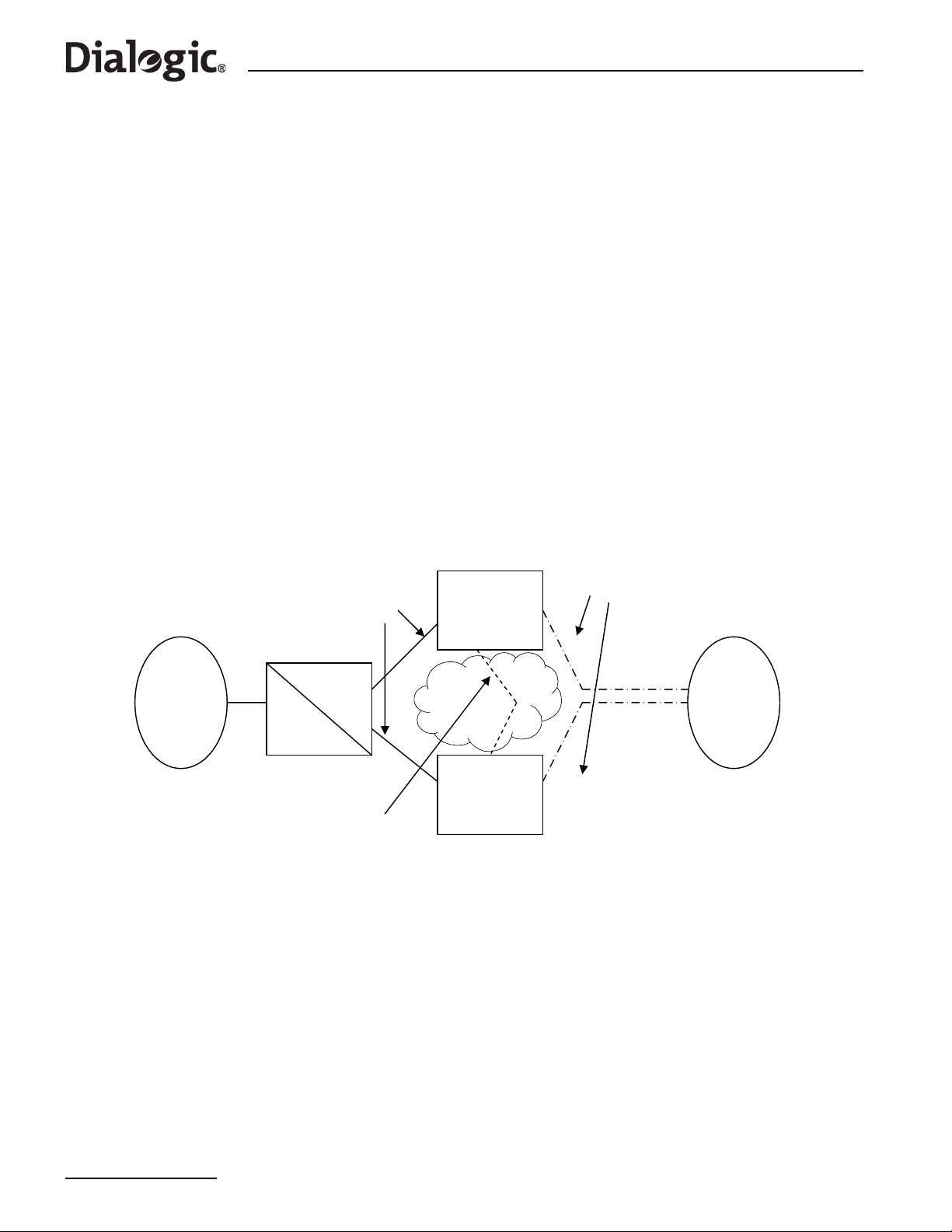
The Signaling Gateway may be configured as part of a Dual-Resilient pair; that is, two SS7G2x units
appearing to the network as a single point code. If the SS7 network loses accessibility of one unit, the point
code status remains unaffected.
®
Figure 3 shows a dual resilient system with two Dialogic
network and an M3UA ASP. To achieve this configuration, the following additions to the normal configuration
must be made:
1. The configuration of an inter -S S7G2x link set. This has the same DPC and OPC. This link set may consist
of MTP2 links, M2PA links or a combination of both.
2. Each C7Route must be configured to use a preferred link set LS1 and a backup link set LS2.
3. Each SS7G2x must be configured with a C7Route to the other SS7G2x using only LS2.
Note: Since both SS7G2xs have C7Links that are part of the same link set (from the perspective of the
adjacent point code), care must be taken in the assignment of SLCs.
SS7G2xs products connected to an STP in the SS7
Figure 3. Dual Resilient Configuration
M3UA Links
LS1
SS7G2x 1
PC 1
PC 3
STP
PC 2
ASP
SS7G2x 1
PC 1
LS2
Inter SS7G2x
Linkset
(shown as M2PA)
See Chapter 7, “Configuration Overview” for a more in depth discussion of Dual Resilient configuration.
14

®
Dialogic
SS7G2x Signaling Server SGW Mode User Manual Issue 4
Chapter 2: Specification
2.1 Hardware Specification
®
Full details of the Signaling Gateway hardware specification are given in the Dialogic
Hardware Manual.
2.2 System Capacity
The maximum capacity is dependent on the number and type of signaling boards installed. The numbers
given in this section are for a single unit. Use of Signaling Gateways in dual pairs or in clusters proportionally
increases the capacity of the overall system while still acting as a single SS7 point code.
2.3 System Capabilities
SS7G21 and SS7G22
• Maximum number of signaling boards: 3
• Number of 10/100/1000 Mbit/sec Ethernet interfaces: 4
2.4 Signaling Capabilities (Per System)
• Maximum number of SS7 Signaling Links (including M2PA): 128
• Maximum number of M2PA Signaling Links: 32
Note: A system supports up to 128 SS7 links, where each link can be used for either M2PA or MTP2.
The number of SS7 links used for M2 PA reduces the number of links available for MTP2 and viceversa. For example, if 32 SS7 links are used for M2PA, 96 links are available for MTP2.
• Maximum number of SS7 link sets: 64
• Maximum number of SS7 routes: 128 per network
• Maximum number of Networks: 4
• Maximum number of Application Servers: 200
• Maximum number of Application Servers: 200
• Maximum number of M3UA routes: 200
• Maximum number of Network Contexts: 4
2.5 Physical Interfaces (Per Signaling Board)
• SPCI2S T1/E1 PCM interfaces: 2
• SPCI2S SS7 V.11 serial interfaces: 2
• SPCI4 T1/E1 PCM interfaces: 4
• SS7HDP T1/E1 PCM interfaces: 4
2.6 TDM Signaling Capabilities (Per Signaling Board)
• Maximum number of SS7 Signaling Links (SPCI4 / SPCI2S): 4
• Maximum number of SS7 Signaling Links (SS7HDP): 64
Note: The system limit for a Signaling Gateway is still 128 SS7 Signaling Links even when three
SS7HDP boards are installed.
15

Chapter 3 Installation and Initial Configuration
Chapter 3: Installation and Initial Configuration
3.1 Installation
Note: The Signaling Gateway should only be installed by suitably qualified service personnel. Important
safety and technical details, required for installation, are given in the Dialogic
®
SS7G21 and
SS7G22 Hardware Manual.
In order to complete the installation of the Signaling Gateway unit, follow the steps below:
1. Connect a VT100 terminal to the unit (see Section 3.2).
2. Check whether a software download and upgrade is required (see Section 3.3).
3. Install any additional software option licenses that may have been purchased (see Section 4.14.2,
“Installing System Licenses” on page 28).
4. Change the system type to act as a SIGTRAN Signaling Gateway (see Section 3.4).
5. Set the IP addresses of the unit (see Section 3.4).
6. Apply the configuration to the unit (see Section 3.5).
3.2 Connecting a VT100 Terminal
A VT100 compatible terminal can be connected, using a DKL29 cable, to the serial port (COM2) on the rear of
the unit. After pressing the carriage return (Enter) key, the Signaling Gateway interface prompt is displayed.
Default serial port settings are 9600 baud, 8 data bits, 1 stop bits and no parity bits.
The output on the VT100 screen is one of the following:
SS7G20(SIU) logged on at 2004-01-20 14:52:29
<
to indicate SIU operation
OR
SS7G20(SGW) logged on at 2004-01-20 14:52:29
<
to indicate SGW operation
OR
SS7G20(DSC) logged on at 2004-01-20 14:52:29
<
to indicate DSC operation.
3.3 Software Download
®
Up-to-date information and software downloads for the Dialogic
SS7G2x products can be found at the
following URL:
http://www.dialogic.com/support/helpweb/signaling
The product leaves the factory with fully-functional software installed. We recommend you check the above
URL for any recent revisions, and install them before putting the product into service.
Since it is possible to source units from multiple supply channels, we recommend that each is verified to
ensure that all units in a delivery are at the same software revision.
Follow the steps below:
1. Check the current software version running in the system using the CNSWP command.
2. Check the latest distribution file from the “SS7G2x Signaling Gateway” section on the SS7 Products
download web site:
http://www.dialogic.com/support/helpweb/signaling
16

®
Dialogic
SS7G2x Signaling Server SGW Mode User Manual Issue 4
3. If a download is required, store the distribution file in an empty directory on the hard drive of the
downloading machine.
4. Follow the steps detailed in Section 4.11, “Updating System Software” on page 24 in order to carry out
the update of the system software.
3.4 Initial Configuration
By default, the Signaling Gateway is shipped configured to operate in SIU mode. Once an SGW license has
been applied, the system must be restarted using the MNRSI MML command requesting that the unit operate
in SGW mode. Connect a VT100 terminal to identify the mode of operation (See Section 3.2, “Connecting a
VT100 Terminal” on page 16).
The MNRSI restart command should be used to restart the system in a different mode. MNRSI should be
used together with the mode in which the Signaling Gateway is expected to operate in after restart. For SGW
operation this is:
MNRSI:SYSTYPE=SGW;
The Signaling Gateway is configured with a default IP address of 192.168.0.1. If this address is not unique,
or not suitable for the existing network configuration, it is necessary to change this value to a unique IP
address in the Ethernet network to which it is connected. Instructions for making this change are given
below.
Using the VT100-compatible terminal, the IP address is set by entering the system configuration command,
CNSYS. For example, to set the IP address to 123.124.125.126, the following command should be entered:
CNSYS:IPADDR=123.124.125.126;
It is also possible to configure a subnet mask if the unit is a member of a subnet. The default subnet mask is
255.255.255.0. To set the subnet mask to a different value, the following command should be used (the
example here sets a subnet mask of 255.255.255.192):
CNSYS:SUBNET=255.255.255.192;
The management interface also allows an IP gateway address to be specified using the GATEWAY parameter.
This is set by default to 0.0.0.0, indicating that no gateway is present. For example, to set the gateway
address to 123.124.125.250, the following command is used:
CNSYS:GATEWAY=123.124.124.250;
The current settings can be displayed by entering the CNSYP command.
CNSYP;
The configuration is displayed in the format shown below:
System Configuration
UNITID: 0004238734ef
SYSID:
SYSREF: 0
PASSWORD: ********
FTPPWD: N
FTPSER: Y
SECURE: N
PER: 0
IPADDR: 172.28.148.99
SUBNET: 255.255.255.0
IPADDR2: 170.28.148.100
SUBNET2: 255.255.255.0
IPADDR3: 170.28.148.101
SUBNET3: 255.255.255.0
IPADDR4: 0.0.0.0
SUBNET4: 255.255.255.0
GATEWAY: 172.28.148.1
SNMP: N
SGW: Y
DSC: N
SIU: N
EXECUTED
17

Chapter 3 Installation and Initial Configuration
Note: The protocol and mode parameters are only present if licensed. When a protocol or mode is
active, the parameter shows the value “Y”, and when inactive, the parameter shows the value
“N”.
The new IP address parameters is initialized with immediate effect . If the IP address used to login to the unit
for the telnet session is changed, the user is automatically logged out of the session. However, the user can
log in again without delay using the new IP address.
The Ethernet connection should be verified by attempting to “ping” the SGW from a computer connected to
the same Ethernet network, using the following command:
ping 123.124.125.126
If the Signaling Gateway has been configured correctly, it responds to the ping and the host machine displays
a message confirming communication with the Signaling Gateway (the exact format and response of this
message is operating system dependant).
If ping fails, the user should check that the IP address was entered correctly and that there is no fault with
the cabling to the Signaling Gateway.
Once the ping command shows that the Ethernet connection is valid, it should be possible to access the
management interface previously used on the VT100 compatible terminal via telnet. This is achieved by
establishing a telnet session to port 8100 or 8101.
Note: It is not possible to telnet to the standard telnet port 23.
For example, on a typical host console, the following command starts a telnet session to a Signaling Gateway
with an IP address of 123.124.125.126:
telnet 123.124.125.126 8100
The telnet terminal displays the MML interface prompt:
SS7G20(SGW) logged on at 2004-01-20 14:52:29
<
An optional password can be set to control remote access to the MML. This is also done using the CNSYS
command:
CNSYS:PASSWORD=password,CONFIRM=password;
If set, a user opening a telnet session to the MML is prompted to enter a password, for example:
SS7G20(SGW) logged on at 2004-01-20 14:52:29
password:
Password access can be removed by specifying “null” values for the PASSWORD and CONFIRM parameters,
that is:
CNSYS:PASSWORD=,CONFIRM=;
For additional security, the units support the use of Secure Shell (SSH) tunnelling for telnet and secure FTP
operation. The user should use the CNSYS command to restrict telnet access to "telnet via SSH tunnelling"
only. For example:
18
CNSYS:SECURE=Y;
Note: The unit does not provide a Secure Shell session connection. Your SSH client may need additional
configuration to allow SSH tunnelling without a session connection.

®
Dialogic
SS7G2x Signaling Server SGW Mode User Manual Issue 4
Once activated, a future user is required to set up an SSH tunnel prior to telnet access. For a client on a
Linux® or Solaris™ like operating system, login for telnet using the ssh application. The ssh application should
be invoked using a shellscript of the following form:
#!/bin/sh
ssh -l siuftp -C -f $1 -L 2323:$1:8101 sleep 5
telnet localhost 2323
3.5 Configuration Procedure
Once the system architecture and protocol configuration is known, it is necessary to set this configuration
within the Signaling Gateway. Configuration is achieved using MML commands as described in Chapter 6,
“Command Definitions”. An overview of configuration is provided in Chapter 7, “Configuration Overview” and
example configurations are described in Chapter 11, “Worke d Conf iguration Examples”.
19

Chapter 4 Operation
Chapter 4: Operation
4.1 General
The Signaling Gateway can be configured by the user from either serial port 2 (COM2, on the rear panel) or
by using telnet over the Ethernet interface. The serial port can be configured over a range of baud rates and
parity. The default configuration for the port is 9600 bits/s, 8 data bits, 1 stop bit, and no parity. Serial port
1 (COM1, on the front panel) is not supported on the SS7G2x. Flow control can be set to either NONE or
XON/XOFF on the terminal used to communicate with the serial interface of the SS7G2x.
The commands that make up the Signaling Gateway Man-Machine Interface Language (MML) are based on
the CCITT blue book recommendations Z.311 to Z.317.
In the following description, input text, numerals and characters that th e user is expected to enter are shown
in bold text and responses displayed on the screen are shown in fixed width text. S yntax elements that are
further defined are shown in angle brackets, for example, <time of day>.
4.2 Log On/Off Procedure
To initiate a dialog with the Signaling Gateway, the operator must “log on” to one of the MML interfaces.
T o log on to the serial port when it is configured to use DTR/DSR, the connected terminal should assert DSR.
The Signaling Gateway asserts DTR in response and the user can then enter into a dialog with the Signaling
Gateway. The session is ended by operator command to the Signaling Gateway, or by the terminal
deasserting DSR or at the expiry of an auto log off timer. The Signaling Gateway deasserts DTR in response
to any one of these three. To log on again, DSR must first be deasserted.
To log on to the serial port when it is not configured to use DTR/DSR, the carriage return key should be
entered. The session is ended by operator command to the Signaling Gateway or at the expiry of an auto log
off timer.
The two telnet connections provided are accessed using a standard telnet utility . Only ports 8100 and 8101 can
be used. The default port 23 should not be used.
If a password is specified for the system, when logging on, the password is required before being allowed to
continue. If an incorrect password is entered, the system again prompts for a password. If an incorrect
password is entered three times, the port is disconnected. For safety, the password is never required on the
serial port.
When the connection is established, a message consisting of the system identity followed by:
logged on at <calendar date> <time of day>
is displayed, followed by the command prompt, which is the less than symbol (<). The logon session is
ended either by operator command or at the end of an auto log off time out.
The system maintains two timers during the log on session: an “auto log off warning” timer and a “auto log
off” timer. Both are restarted each time a new command is input. When the auto log off warning time out
expires, an auto log off warning message is output to the terminal and any partially entered command is
discarded. The system then outputs a command prompt to the terminal. If no command is input before the
auto log off time out expires, the log on session is ended. The duration of both these timers is userconfigurable and can even be disabled completely.
When log off is initiated, a message consisting of the system identity followed by:
logged off at <calendar date> <time of day>
is output to the operator’s terminal. The Signaling Gateway then initiates the appropriate procedure to end
the connection to the operator’s terminal.
20

®
Dialogic
SS7G2x Signaling Server SGW Mode User Manual Issue 4
4.3 Command Character Set and Syntax
The only characters used for commands and parameters are:
• The letters A to Z and a to z, referred to as <letter>. The case of characters in command names and
parameter names is not significant.
• The digits 0 to 9, referred to as <digit>
• - (hyphen), CR (FE5), SP (space), $(dollar), & (ampersand), * (asterisk),
: (colon), ; (semicolon) / (solidus), . (full stop/period) and = (equals sign)
• The DEL (Delete) character or the BS (Backspace) character is used to delete characters on the current
line.
• The CAN character (Ctrl X) is used as an abort character.
It is possible to indicate several simple values for the same parameter by grouping parameter arguments
using the operators & or &&. For example, 3&6 indicates the simple parameter arguments 3 and 6. A
sequence of consecutive simple parameter arguments is indicated by writing the lower and upper simple
parameter arguments separated by &&, hence 4&&8 indicates the simple parameter arguments 4, 5, 6, 7
and 8.
Comments are allowed in command input, and can appear in any position on the command line. A comment
is defined as a character string enclosed between the separators /* (solidus asterisk) and */ (asterisk
solidus), where the character string can contain any characters except the format effector characters (HT –
Horizontal Tab, LF – Line Feed, VT – Vertical Tab, FF – Form Feed and CR – Carriage Return) and the
sequence */.
4.4 Command Formats
To allow easy command recognition and familiarization, all the commands share a common five character
format:
XXYYZ
where:
• XX = Command group
• YY = Function within group
• Z = Operation code
The following operation codes are used:
• C = Change
• E = End
• I = Initiate
• P = Print
• S = Set
Note: The term “print” refers to output to the serial port in use for the dialog procedure.
4.5 Command Entry
Each character entered is echoed to the operator’s terminal. The BS (backspace) or DEL (delete) character
can be used to delete characters entered within the current line. This causes the Signaling Gateway to output
the sequence BS space BS. On a visual display terminal, this has the effect of deleting the last character
entered from the display.
Commands can be entered whenever the command prompt has been output. Commands are terminated by
a semicolon (;) followed by CR. Commands may exceed one line on the terminal, but may not exceed 100
characters.
If a command takes parameters, a colon is used to separate the command from the parameters. A comma
(,) is used to separate multiple parameters.
21

Chapter 4 Operation
To ensure correct operation of the character deletion, the maximum number of characters entered on a
single command line should be no greater than the number of characters that can be displayed on a single
line of the terminal (to prevent text “wrap around”). If a command is longer than one line, each line before
the last should be terminated with a complete parameter value followed by a comma and CR. The command
can then continue on the next line. If the user wishes to specify more parameters than can be entered on a
single initiate command, they should use the initiate command to enter mandatory parameters, then use a
change command to specify additional parameters.
A partially entered command can be aborted using the CAN character. The system outputs an indication that
the command has been aborted, followed by a prompt for new command input. The CAN character can also
be used to abort an output listing on the operators terminal.
4.6 Dangerous Commands
Commands that affect the Signaling Gateway operation are considered DANGEROUS commands. When a
DANGEROUS command is entered the Signaling Gateway outputs the following on a new line:
Are you sure? [Y/N]
The operator must enter Y followed by CR to continue the execution of the command. Any other valid input
character apart from SP or CR, followed by CR, causes the command to be aborted.
4.7 Changing Configuration Data
Many configuration commands require that certain other commands have been entered first (for example to
block a link before removing a boards configuration). These rules are described on a per-command basis as
prerequisites.
4.8 Command Responses
The Signaling Gateway does not, in general, produce output unless in response to an operator command.
The only exception to this is the auto log off warning message and the log off message (when log off is
initiated automatically).
The auto log off warning message is as follows:
WARNING: Auto log off imminent!
When a syntactically correct command has been issued to the Signaling Gateway, acceptance is indicated by
the Command Executed output as follows:
EXECUTED
An invalid command is not acted upon. The Signaling Gateway indicates command rejection by issuing one of
the responses in Table 1. Onl y the fi rst error detected in a command is indicated.
Table 1. Command Rejection Responses
Response Reason for Rejection
UNACCEPTABLE COMMAND
UNKNOWN COMMAND The command is not recognized.
NO SYSTEM RESOURCES
INVALID PARAMETER NAME A parameter name has been entered that is not v alid for this command.
EXTRA PARAMETERS Too many parameters have b een entered.
MISSING PARAMETER A required parameter has not been input.
INCONSISTENT PARAMETER The parameters input are not valid together for the command.
MISSING DATA A parameter has no data.
INCONSISTENT DATA
RANGE ERROR The value assigned to a numeric parameter is outside the valid range.
The command is valid but not in the current state of the equipment (for
example, changing a signaling link configuration without blocking).
The requested command cannot be execu ted due to unav ailable system
resources.
The values of parameters are in cons iste nt wit h e ach othe r or with data
already entered into the system.
22

®
Dialogic
SS7G2x Signaling Server SGW Mode User Manual Issue 4
Table 1. Command Rejection Responses (Continued)
Response Reason for Rejection
INVALID INFORMATION GROUPING
INVALID INDICATOR
GENERAL ERROR
INTERNAL ERROR Command failed to complete due to internal error.
INVALID INFORMATION UNIT The value entered for a parameter is not valid for that parameter.
UNKNOWN SEPARATOR The character used to separate two parameters is not recognized.
The type of information grouping used in the input of the parameter
value is not valid.
This command contains a ‘format character’ (‘:’, ‘;’, etc.) that is not
valid for this command.
Command unable to execute due to an external error (for example, a
missing or write-protected CDROM).
4.9 FTP Access
The Signaling Gateway supports FTP server operation allowing the user to perform maintenance operations,
such as software, license and configuration update without the use of MML as well as providing access to
locally stored continuous records and periodic reports.
An FTP session should be established between the remote machine and the Signaling Gateway by entering
the appropriate command on the remote machine's keyboard, for example:
ftp 123.124.125.125
The FTP server can be activated or deactivated using the FTPSER parameter on the CNSYS command.
The appropriate user name and password to use depends on whether the FTPPWD option has been set to Y
using the CNSYS MML command.
When FTPPWD = Y, FTP access must use the fixed user name “siuftp” in conjunction with the normal MML
access password as configured by setting the CNSYS parameter PASSWORD.
Access to the Signaling Gateway using other user accounts except “siuftp” is denied. Note also that access is
denied if FTPPWD = Y, but there is no MML password.
When FTPPWD=N, no FTP access is permitted. Access with “siuftp” or any other user account is disabled.
Therefore, the user is strongly advised to activate FTP password security.
The state of FTPPWD can be viewed using the CNSYP command.
For additional security, the Signaling Gateway supports the use of Secure Shell (SSH) access for FTP
operation. The user should use the CNSYS command to allow only secure FTP access to the unit, for
example:
CNSYS:SECURE=Y;
For a client on a UNIX operating system, the command sequence to log in for FTP access using the sftp
application is:
sftp -l ftp@<IP Address>
The user is also prompted to enter the password for the siuftp login account.
®
The secure connection to a unit can also be established from Windows
operating system using the
appropriate SSH software.
23

Chapter 4 Operation
4.10 Backing Up System Software
The user can backup a binary copy of the Signaling Gateway software for restoration later.
4.10.1 Software Backup to a Remote Data Centre
The procedure to perform a software backup to an Remote Data Center (RDC) is as follows:
1. The user should enter:
CNBUI: RDC=<rdc id>, DTYPE=SOFTWARE,
DIRECTORY=<subdirectory>,FILE=<filename>;
to request that the software be backed up to an RDC where the software file <filename.tgz> is stored in
a subdirectory in the ftproot.
Note: The user should not use a filename of “sgw” when backing up to the local RDC.
The unit indicates that the configuration has been successfully backed up by displaying the “EXECUTED”
response to the CNBUI command.
4.11 Updating System Software
The configuration data, stored in non-volatile memory, is not affected by a software update.
Normal operation of the software update procedure uses MML to update the software. While a software
update can take place while phone calls are in progress, the new software is not activated until the system is
restarted.
On completion of the software update, the user must perform a system restart. MML commands are
restricted to the following “safe” mode commands CNSYS, CNUPI and STRDP commands, as well as the
alarm log and configuration print commands.
If the user aborts the software update or the software update process fails, the system alarm “SW
mismatch” is activated and the user is restricted to “safe” mode commands. If the user restarts the system
in this state, the system restarts in “safe” mode running limited configuration only software.
Note: Prior to performing a system upgrade, it is recommended that the user makes a backup of the
system configuration using the procedures specified in Section 4.12, “Backing Up Configuration
Data” on page 25.
4.11.1 Software Update from a Remote Data Centre
The procedure to perform a software update from a Remote Data Center (RDC) is as follows:
1. The user should enter:
CNUPI:DTYPE=SOFTWARE,RDC=<rdc id>,
DIRECTORY=<subdirectory>,FILE=<filename>;
to request that the software be updated from a RDC where the software update files are stored in a
subdirectory in the ftproot.
Note: The directory and filename are optional and when not used the system looks for the file sgw.tgz in
the ftproot directory. If <filename> is specified, it should be specified without an extension.
2. Once the user has confirmed that the software should be upgraded, the distribution file is transferred to
the Signaling Gateway without further interaction with the user. The unit indicates that the file has been
successfully transferred by displaying the “EXECUTED” response to the CNUPI command.
3. On completion, the user should restart the system by executing the MNRSI command.
4.11.2 Software Update from CD-ROM
The following procedure assumes that a CD-ROM with the updated software has already been created.
Perform the software update as follows:
1. Insert the CD in the CD ROM drive.
2. Enter the following command:
24

®
Dialogic
SS7G2x Signaling Server SGW Mode User Manual Issue 4
CNUPI:DTYPE=SOFTWARE,DIRECTORY=<subdirectory>,FILE=<filename>;
to request that the software be updated from CD ROM.
Note: The directory and filename are optional and when not used the system looks for the file sgw.tgz in
the CR ROM root directory.
3. Prompts are displayed asking first if the user is certain that they wish to upgrade the software and then
to put the first software update disk in the CD ROM drive.
The software is uploaded from the distribution CD to the Signaling Gateway.
The unit indicates that all files have been successfully transferred by displaying the “EXECUTED”
response to the CNUPI command.
4. The user should restart the system by entering the MML command MNRSI.
4.11.3 Software Update from Startup
The user is also able to update the software from system start. Installation of software from system start is
not normal operating procedure and should only be used if the user is unable to install software via MML. A
failed installation of software from system start can result in the system failing to operate. The procedure to
install software from system start using either FTP or CD is as follows:
Software Update from Startup Using FTP
1. Rename the software distribution to sgw.tgz.
2. Establish an FTP session (see Section 4.9, “FTP Access” on page 23).
3. Set the FTP transfer mode to “Binary”, since the software file is a binary file.
4. Transfer the software to the Signaling Gateway by typing the command “put sgw.tgz sgw.tgz”.
Note: The Signaling Gateway uses a case-sensitive file system. Therefore, it is necessary to specify
sgw.tgz in lower ca s e .
5. Terminate the FTP session by entering “quit” or “bye”.
6. Establish an MML session and restart the unit by typing the MNRSI command.
The machine then boots and completes the upgrade. Once the upgrade is complete, the machine is
accessible via the MML.
7. Check the software version using the CNSWP command.
Software Update from Startup Using a CD
1. Place the CD containing the file sgw.tgz in the CD ROM drive.
2. Restart the system.
The new software is installed and started automatically.
4.12 Backing Up Configuration Data
The user can backup a binary copy of the Signaling Gateway configuration for restoration later.
4.12.1 Configuration Backup to Remote Data Centre
The procedure to perform a configuration backup to an RDC is as follows:
1. The user should enter:
CNBUI:RDC=<rdc id>, DTYPE=CONFIG,
DIRECTORY=<subdirectory>,FILE=<filename>;
to request that the configuration be backed up to an RDC where the configuration file <filename.CF3> is
stored in a subdirectory in the ftproot.
Note: The user should not use a filename of “SDC” when backing up to the local RDC.
The unit indicates that the configuration has been successfully backed up by displaying the “EXECUTED”
response to the CNBUI command.
25

Chapter 4 Operation
4.13 Updating Configuration Data
Valid configuration data can be stored by the Signaling Gateway at a Remote Data Center (RDC) using the
CNBUI command (see Section 4.12), on CD ROM or on a remote machine accessible via FTP. This
configuration data can then be restored as described in the following subsections.
4.13.1 Configuration Update from a Remote Data Centre
The procedure to perform a configuration update from a Remote Data Center (RDC) is as follows:
1. The user should enter:
CNUPI:DTYPE=CONFIG,RDC=<rdc id>,
DIRECTORY=<subdirectory>,FILE=<filename>;
to request that the configuration be updated from a RDC where the configuration update file
<filename.CF3> is stored in a subdirectory in the ftproot.
Note: The directory and filename are optional and when not used the system looks for the SDC.CF3 file
in the ftproot directory.
The unit indicates that the configuration has been successfully transferred by displaying the “EXECUTED”
response to the CNUPI command.
2. The user should then restart the system by entering the MML command MNRSI.
4.13.2 Configuration Update from CD ROM
The procedure for a configuration update from CD ROM using MML is as follows:
1. The user should enter:
CNUPI:DTYPE=CONFIG, DIRECTORY=<subdirectory>,FILE=<filename>;
to request that the configuration file be updated from CD ROM.
Note: The directory and filename are optional and when not used the system looks for the SDC.CF3 file
in the CD ROM root directory.
The configuration file is uploaded from CD ROM. The unit indicates that the configuration has been
successfully updated by displaying the “EXECUTED” response to the CNUPI command.
2. The user should then restart the system by entering the MML command MNRSI.
4.13.3 Configuration Update from Startup
The user is also able to install a previously backed-up system configuration from system start.
Note: Installation of configuration from system start is not normal operating procedure and should only
be used if the user is unable to install configuration via MML. A failed installation of configuration
from system start can result in the complete loss of system configuration.
The procedures to install configuration from system start using either FTP or CD are described below.
Configuration Update from Startup using FTP
1. Rename the software distribution to SDC.CF3.
2. Establish an FTP session (see Section 4.9, “FTP Access” on page 23).
3. Set the FTP transfer mode to “Binary”, since the software file is a binary file.
4. Transfer the configuration to the Signaling Gateway by entering the command “put SDC.CF3 SDC.CF3”.
Note: The Signaling Gateway uses a case-sensitive file system. Therefore, it is necessary to specify
SDC.CF3 in uppercase.
5. Terminate the FTP session by entering “quit” or “bye”.
6. Establish an MML session and restart the unit by typing the MNRSI command.
The machine then boots and completes the upgrade. Once the upgrade is complete, the machine is
accessible via the MML.
26

®
Dialogic
SS7G2x Signaling Server SGW Mode User Manual Issue 4
Software Update from Startup using a CD
1. Place the CD containing the sgw.tgz file in the CD ROM drive.
2. Restart the system.
The new configuration is installed and started automatically.
4.14 System Licenses
Each mode of operation (SIU, DSC or SGW) supports a number of different protocol and software options.
This section describes how additional licenses are purchased and installed on a system.
4.14.1 Purchasing System Licenses
The user should place an order using their normal sales channel quoting the item market name for the
software option required. The supported item market names are:
For the SIU Mode of operation, the following protocols may be run on the unit by purchasing the licenses:
• SS7SBG20ISUP
• SS7SBG20SCCPCL (connectionless SCCP)
• SS7SBG20SCCPCO (connection-orientated SCCP)
• SS7SBG20TCAP
• SS7SBG20MAP
• SS7SBG20IS41
• SS7SBG20INAP
For the SGW Mode of operation, which incorporates the proto cols MTP2, MTP3, M3UA and M2P A (inter-links),
the user needs to purchase the license:
• SS7SBG20SGW
If the user also requires to use M2PA Network facing links, this will require purchase of the license:
• SS7SBG20M2PA
For the DSC Mode of operation, which incorporates the protocols MTP2, MTP3, ISUP, ISDN, DPNSS and M2PA
(inter-links), the user needs to purchase the license:
• SS7SBG20DSC
If the user also requires to use M2PA Network facing links, this will require purchase of the license:
• SS7SBG20M2PA
At this point in the process, there is no need to know details of the specific Dialogic
which the option is to be installed (the target SS7G2x).
The order ships through the normal supply channels and the user receives a paper Licence Certificate. The
certificate contains the full licence terms for using the SS7G20 software option and a unique Licence ID that
is needed to activate the licence.
When the Licence Certificate is received, the user should first read the full terms of the software licence:
®
SS7G2x product on
• If the user does not agree with the software licence terms, they must contact their sales channel for a
refund and must not activate the software licence.
• If the user agrees the software licence terms, they can continue with the process following.
The next stage is to identify the SS7G2x on which the software option is to be activated. To do this, it is
necessary to obtain the UNIT ID for the SS7G2x, which is obtained by executing the CNSYP MML command
on the target SS7G2x.
Once the user has the Licence ID and the UNIT ID, the licence can be activated on the Dialogic
products. Licence Activation is the process of submitting the License ID and UNIT ID so that a Licence File
can be generated and sent for installation on the target SS7G2x.
®
SS7G2x
27

Chapter 4 Operation
The Licence Activation process is web-based and the Licence File is sent by email.
The user performs License Activation by visiting the web site:
http://membersresource.dialogic.com/ss7/license/license.asp (or an alternative URL if listed on the Licence
Certificate).
The user is asked to provide the following basic information:
• Name
• Company
• Country
• Email address (this is used to send the Licence File)
The user is then asked for the following information about the SS7G2x:
• Operating System - Enter “Systems Product”.
• Host ID - Enter the UNIT ID.
• User Machine Identification (a string, typically the Signaling Gateway name, used by the user to identify
the SS7G2x).
The user must list the Licence ID (taken from the Licence Certificate) for each protocol that is to be licensed
on the target SS7G2x.
Once all this information has been entered, the form should be submitted. The user receives confirmation
that their request has been submitted. Subsequently, they receive their Licence File by email.
For installing system licenses, see Section 4.14.2, “Installing System Licenses” on page 28.
4.14.2 Installing System Licenses
This section describes how additional licenses are installed on an SS7G2x. Each SS7G2x is licensed to run
specific components of the protocol stack. The CNSYP command provides a printout that shows which
components are licensed on a particular unit. Each unit is uniquely identified by a unit identity value, which is
displayed as the UNITID parameter in the CNSYP command output.
The License File, purchased as described in Chapter 3, “System Licenses”, is a simple text file. The contents
of the file are similar to the following:
FEATURE SGW_G20 INTEL 1.000 permanent uncounted \
HOSTID=00d0b8a1aba1 SIGN=1E48C256bb1a
Normal operation of the license update procedure uses MML to update the system’ s purchasable licenses with
the file taken directly from a Remote Data Centre (RDC).
Note: If the licensing upgrade fails, the unit restores the previous licensing level.
4.14.3 License Update from Remote Data Centre
The procedure to perform a license update from the a Remote Data Center (RDC) is as follows:
1. The user should enter:
CNUPI:DTYPE=LICENSE,RDC=<rdc id>,DIRECTORY=<subdirectory>;
to request that the license be updated from a RDC where the license file is stored in a subdirectory in the
ftproot.
2. Once the user has confirmed that the license should be updated, the license file is transferred to the
Signaling Gateway without further interaction with the user. The unit indicates that the file has been
successfully transferred by displaying the “EXECUTED” response to the CNUPI command.
28

®
Dialogic
SS7G2x Signaling Server SGW Mode User Manual Issue 4
4.14.4 License Update by FTP
The user is also able to install licenses from system start.
Note: Installation of licenses from system start is not normal operating procedure and should only be
used if the user is unable to install licenses via MML.
The procedure to install licenses from system start is as follows:
1. Rename the purchased license file to sgw.lic.
2. Establish an FTP session (see Section 4.9, “FTP Access” on page 23).
3. Set the FTP transfer mode to “ASCII”, since the license file is a text file.
4. Transfer the software license to the Signaling Gateway by typing the command “put sgw. lic sgw.lic”.
Note: The Signaling Gateway uses a case-sensitive file system. Therefore, it is necessary to specify
sgw.lic in lowercase.
5. Terminate the FTP session by entering “quit” or “bye”.
6. Establish an MML session and restart the unit by typing the MNRSI command.
The machine then boots and completes the upgrade. Once the upgrade is complete, the machine is
accessible via MML.
7. Check the licenses using the CNSYP command.
29

Chapter 5 Parameter Definitions
Chapter 5: Parameter Definitions
5.1 Parameter Table
Table 2 lists all parameters and details the possible values.
All numeric parameters are entered and output in decimal notation.
<text character> is either <lower case letter>, <upper case letter>, <digit>, $, or -. The use of quotation
marks to delimit text strings is not required.
Table 2. Parameter Definitions
Name Description Range Notes
ALP
AS
BCIC
BPOS
BRDTYPE
BUILDOUT
C7LINK Logical reference for an SS7 signaling link 1 to 128
C7RT Logical reference of an SS7 route 1 to 128
CLA
CODE Fault code of a system alarm 1 to 256
CONFIRM
CRTYPE
Sequential reference number of an entry in
the Alarm Log
Logical reference for a SIGTRAN Application
Server
The circuit identification code of an SS7
circuit that is the base CIC of a CIC Range
Board position number (for signaling
boards)
Board type descriptor, in the format:
xxxxxx-y-z
where:
• xxxxxx = board type
• y = number of signaling links
configured on the board
• z = number of PCM ports on the board
See Section 5.4, “Board Types” on page 39.
The buildout type:
• 0 - Setting for E1 devices.
• 1 - T1 short haul 0 - 110 ft.
• 2 - T1 short haul 0 - 110 ft.
• 3 - T1 short haul 110 - 220 ft.
• 4 - T1 short haul 220 - 330 ft.
• 5 - T1 short haul 330 - 440 ft.
• 6 - T1 short haul 440 - 550 ft.
• 7 - T1 short haul 550 - 660 ft.
• 8 - T1 long haul LB0 (-0dB)
• 9 - T1 long haul LB0 (-7.5dB)
• 10 - T1 long haul LB0 (-15dB)
• 11 - T1 long haul LB0 (0dB TR62411)
Alarm class number. One of:
• 0 = Unreported (the alarm is logged,
but it does not trigger an alarm relay
and is not included in SNMP output.
• 1 = Minor (triggering the MNR alarm
LED and relay)
• 2 = Major (triggering the MJR alarm
LED and relay)
• 3 = Critical (triggering the CRT alarm
LED and relay)
Confirmation of a password used to provide
password control access to MML
The type of continuous record:
• ALARM – alarms that have been
reported to the alarm log
1 to 9999
1 to 200
0 to 4095
1 to 3
One of the following:
• SPCI2S-4-2
• SPCI2S-8-2
• SPCI4-4-4
• SPCI4-8-4
• SS7HDP-64-4
0 to 11
0 to 3
0 to 12 <text
character>
ALARM
Default =
• 0 for E1
• 1 for T1
30
 Loading...