

Page 1

Dialogic® 4000 Media Gateway Series
Integration Note
Mitel SX-2000 Lightware
August 2008 64-0352-01
www.dialogic.com
Page 2

Copyright and Legal Notice
Copyright © 2008 Dialogic Corporation. All Rights Reserved. You may not reproduce this document in whole or in part without permission in
writing from Dialogic Corporation at the address provided below.
All contents of this document are furnished for informational use only and are subject to change without notice and do not represent a
commitment on the part of Dialogic Corporation or its subsidiaries (“Dialogic”). Reasonable effort is made to ensure the accuracy of the
information contained in the document. However, Dialogic does not warrant the accuracy of this information and cannot accept responsibility
for errors, inaccuracies or omissions that may be contained in this document.
INFORMATION IN THIS DOCUMENT IS PROVIDED IN CONNECTION WITH DIALOGIC® PRODUCTS. NO LICENSE, EXPRESS OR IMPLIED, BY
ESTOPPEL OR OTHERWISE, TO ANY INTELLECTUAL PROPERTY RIGHTS IS GRANTED BY THIS DOCUMENT. EXCEPT AS PROVIDED IN A
SIGNED AGREEMENT BETWEEN YOU AND DIALOGIC, DIALOGIC ASSUMES NO LIABILITY WHATSOEVER, AND DIALOGIC DISCLAIMS ANY
EXPRESS OR IMPLIED WARRANTY, RELATING TO SALE AND/OR USE OF DIALOGIC PRODUCTS INCLUDING LIABILITY OR WARRANTIES
RELATING TO FITNESS FOR A PARTICULAR PURPOSE, MERCHANTABILITY, OR INFRINGEMENT OF ANY INTELLECTUAL PROPERTY RIGHT OF
A THIRD PARTY.
Dialogic products are not intended for use in medical, life saving, life sustaining, critical control or safety systems, or in nuclear facility
applications.
Due to differing national regulations and approval requirements, certain Dialogic products may be suitable for use only in specific countries,
and thus may not function properly in other countries. You are responsible for ensuring that your use of such products occurs only in the
countries where such use is suitable. For information on specific products, contact Dialogic Corporation at the address indicated below or on
the web at www.dialogic.com
It is possible that the use or implementation of any one of the concepts, applications, or ideas described in this document, in marketing
collateral produced by or on web pages maintained by Dialogic may infringe one or more patents or other intellectual property rights owned
by third parties. Dialogic does not provide any intellectual property licenses with the sale of Dialogic products other than a license to use
such product in accordance with intellectual property owned or validly licensed by Dialogic and no such licenses are provided except
pursuant to a signed agreement with Dialogic. More detailed information about such intellectual property is available from Dialogic’s legal
department at 9800 Cavendish Blvd., 5th Floor, Montreal, Quebec, Canada H4M 2V9.
Dialogic encourages all users of its products to procure all necessary intellectual property licenses required to implement any
concepts or applications and does not condone or encourage any intellectual property infringement and disclaims any
responsibility related thereto. These intellectual property licenses may differ from country to country and it is the
responsibility of those who develop the concepts or applications to be aware of and comply with different national license
requirements.
Dialogic, Dialogic Pro, Brooktrout, Cantata, SnowShore, Eicon, Eicon Networks, Eiconcard, Diva, SIPcontrol, Diva ISDN, TruFax, Realblocs,
Realcomm 100, NetAccess, Instant ISDN, TRXStream, Exnet, Exnet Connect, EXS, ExchangePlus VSE, Switchkit, N20, Powering The ServiceReady Network, Vantage, Making Innovation Thrive, Connecting People to Information, Connecting to Growth and Shiva, among others as
well as related logos, are either registered trademarks or trademarks of Dialogic. Dialogic's trademarks may be used publicly only with
permission from Dialogic. Such permission may only be granted by Dialogic’s legal department at 9800 Cavendish Blvd., 5th Floor, Montreal,
Quebec, Canada H4M 2V9. Any authorized use of Dialogic's trademarks will be subject to full respect of the trademark guidelines published
by Dialogic from time to time and any use of Dialogic’s trademarks requires proper acknowledgement.
Microsoft and Windows are registered trademarks of Microsoft Corporation in the United States and/or other countries. Other names of
actual companies and products mentioned herein are the trademarks of their respective owners.
This document discusses one or more open source products, systems and/or releases. Dialogic is not responsible for your decision to use
open source in connection with Dialogic products (including without limitation those referred to herein), nor is Dialogic responsible for any
present or future effects such usage might have, including without limitation effects on your products, your business, or your intellectual
property rights.
2
.
Page 3

Dialogic® 4000 Media Gateway Series Integration Note
1. Scope
This document is intended to detail a typical installation and configuration of the Dialogic
Series if used to interface between a PBX and the Microsoft
®
Office Communications Server (OCS) application.
®
4000 Media Gateway
2. Configuration Details
Listed below are details of the PBX and gateways used in the testing on which this document is based.
2.1 PBX
PBX Vendor Mitel
Model(s) SX-2000 Lightware
Software Version(s) Version 34.2.0.20
Additional Notes N/A
2.2 Gateway
Gateway Model Dialogic
®
4000 Media Gateway Series
Software Version(s) Dialogic® Diva® System Release software version 8.3.2 build 459
(formerly called Diva
®
Dialogic
Diva® SIPcontrol™ Software version 1.6 build 46
®
Server software)
(DSSIPControl.msi)
Protocol T1 Q.SIG
2.3 System Diagram
The diagram below details the setup used in the testing and creation of this document. In the diagram, the
abbreviation DMG4000 stands for the Dialogic
Microsoft
®
Office Communications Server (OCS) 2007.
®
4000 Media Gateway Series and OCS Server stands for
3
Page 4
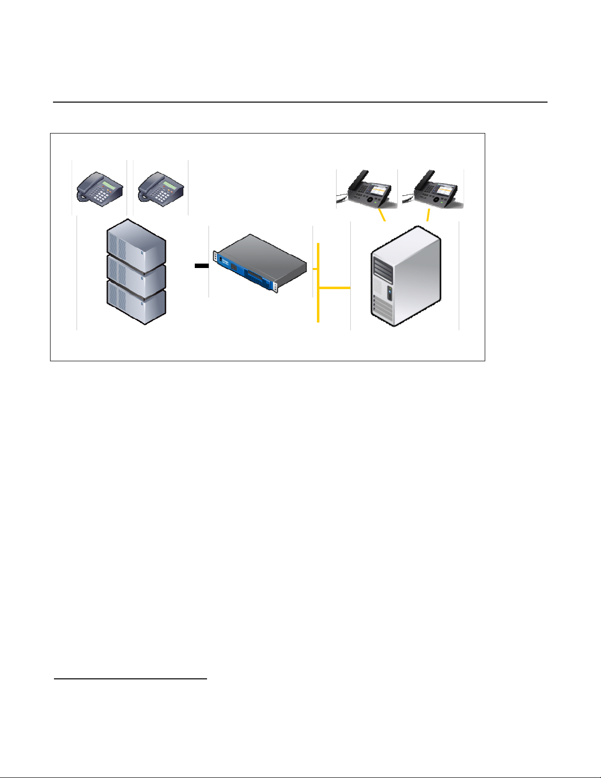
Mitel SX-2000 Lightware
OCS Server
TDM Stations
350 351
OCS Clients
210 211
IP LAN
T1/E1
PBX
3. Prerequisites
3.1 PBX Prerequisites
The PBX must have all supplemental service packages installed for the Q.SIG protocol to operate properly and
to provide all advanced supplemental services.
3.1.1 PBX Equipment Required
To support the T1 Q.SIG configuration as documented you need a Mitel T1 line card.
3.1.2 PBX Cabling Requirements
The cabling for Q.SIG connections must be CAT5e or better. A standard voice quality cable will not provide the
desired signal quality and will cause the gateway to have issues establishing a connection on the D-channel.
3.2 Gateway Prerequisites
The gateway needs to support a T1 Q.SIG interface.
4. Summary of Limitations
No limitations noted as of the last update to this document.
4
DMG4000
Page 5
Dialogic® 4000 Media Gateway Series Integration Note
5. Gateway Setup Notes
Steps for setting up the gateway:
1. Configuration of the Dialogic
2. Configuration of the Dialogic
®
Diva® Media Board drivers.
®
Diva® SIPcontrol™ software.
5.1 Dialogic® Diva® Media Board Configuration
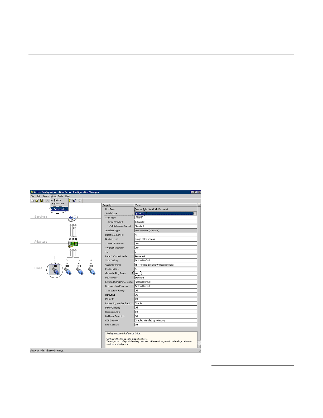
The Diva Media Boards are configured in the Dialogic
Manager, click:
Start > Programs > Dialogic Diva > Configuration Manager.
Note: In the Dialogic
®
®
Diva
software and documentation, Diva Media Boards are referred to as Diva Server
adapters.
A screen similar to the one below will appear.
®
®
Diva
Configuration Manager. To open the Configuration
5
Page 6

Mitel SX-2000 Lightware
Note: The number of TDM circuits varies depending on the used Dialogic® Media Gateway model.
For this setup:
• Set the property Switch Type to Q-SIG T1.
• If your PBX does not provide ring tones to callers from TDM, set the property Generate Ring
Tones to Yes.
To activate the change, click File > Activate.
Make these configuration changes for each TDM circuit you are going to use on the Dialogic
®
Media Gateway.
5.2 Dialogic® Diva® SIPcontrol™ Software Gateway Application
The Diva SIPcontrol software is configured via the web based interface. To open the web interface, click Start
> Dialogic Diva > SIPcontrol Configuration.
On the main page, click the SIPControl link to display the different configuration menus.
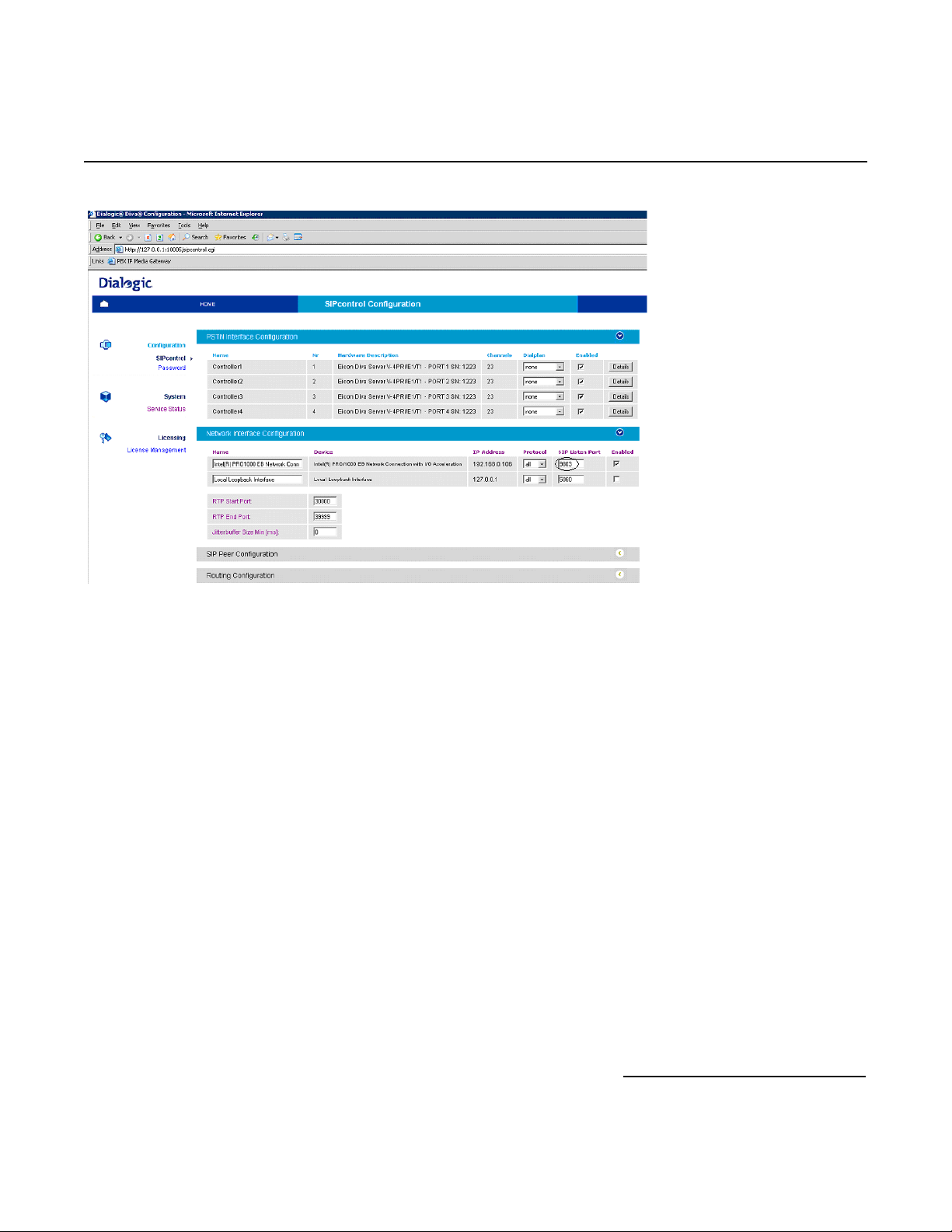
The PSTN Interface Configuration section should automatically include all ports detected in the system.
Note: If you do not see any detected ports, you may need to add http://127.0.0.1
Microsoft
http://127.0.0.1:10005
®
Internet Explorer, click Tools > Internet Options > Security > Trusted Sites. Use
to get to the configuration.
as a trusted site. From
In order for the Diva SIPcontrol software to route calls, the proper routes must be created and configured. Each
route consists of a source interface and a destination interface. PSTN controllers and SIP peers are considered
either a source interface or a destination interface depending on the call direction.
5.2.1 PSTN Interface and Network Interface Configuration
The following is a typical configuration.
6
Page 7
Dialogic® 4000 Media Gateway Series Integration Note
The Network Interface Configuration will be used by the Diva SIPcontrol software for listening to the
SIP traffic from Microsoft
component and the Diva SIPcontrol software are running in the same system, you will need to change SIP
Listen port to 9803 or to an available un-used port. Later during the Microsoft
®
Mediation Server. Given that on these gateways the Microsoft® Mediation Server
®
Mediation Server
configuration, you will need to set the PSTN Gateway next hop setting to 9803 to match.
5.2.2 SIP Peer Configuration
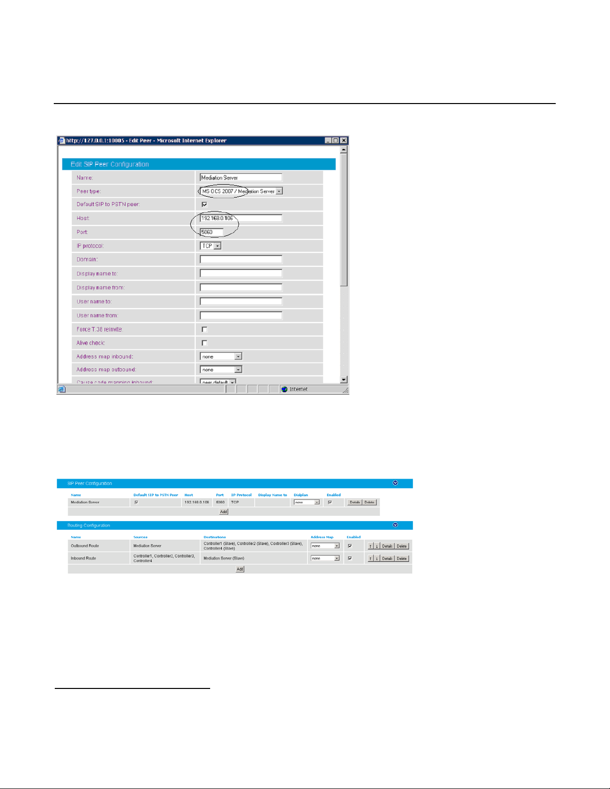
Create one SIP peer to talk to Microsoft
®
Mediation Server as shown below.
7
Page 8
Mitel SX-2000 Lightware
5.2.3 Routing Configuration
In the Routing Configuration section, you must create two routes, one for the inbound direction (TDM to
IP) and one for the outbound direction (IP to TDM). Once you have created the routes, click the Save button for
the changes to take effect.
5.2.4 Number Normalization
The Dialplan Configuration and Address Map Configuration sections are used for manipulating dial
numbers. For most PBX dialplans, an address map is required. See the following examples.
8
Page 9

Dialogic® 4000 Media Gateway Series Integration Note
5.2.4.1 Dialplan Configuration Example
To create a dialplan, click Add from the Dialplan Configuration. The following screens show how to set up
a dialplan for a Microsoft
the PBX. (This may not match to the PBX programming in section 6 and the Setup in section 2.3).
Area code: 716
Base number: 639
Extensions: 4 digits
Access code: 9
®
Office Communications Server (OCS) 2007 application with the following dialplan from
Complete the settings and click OK.
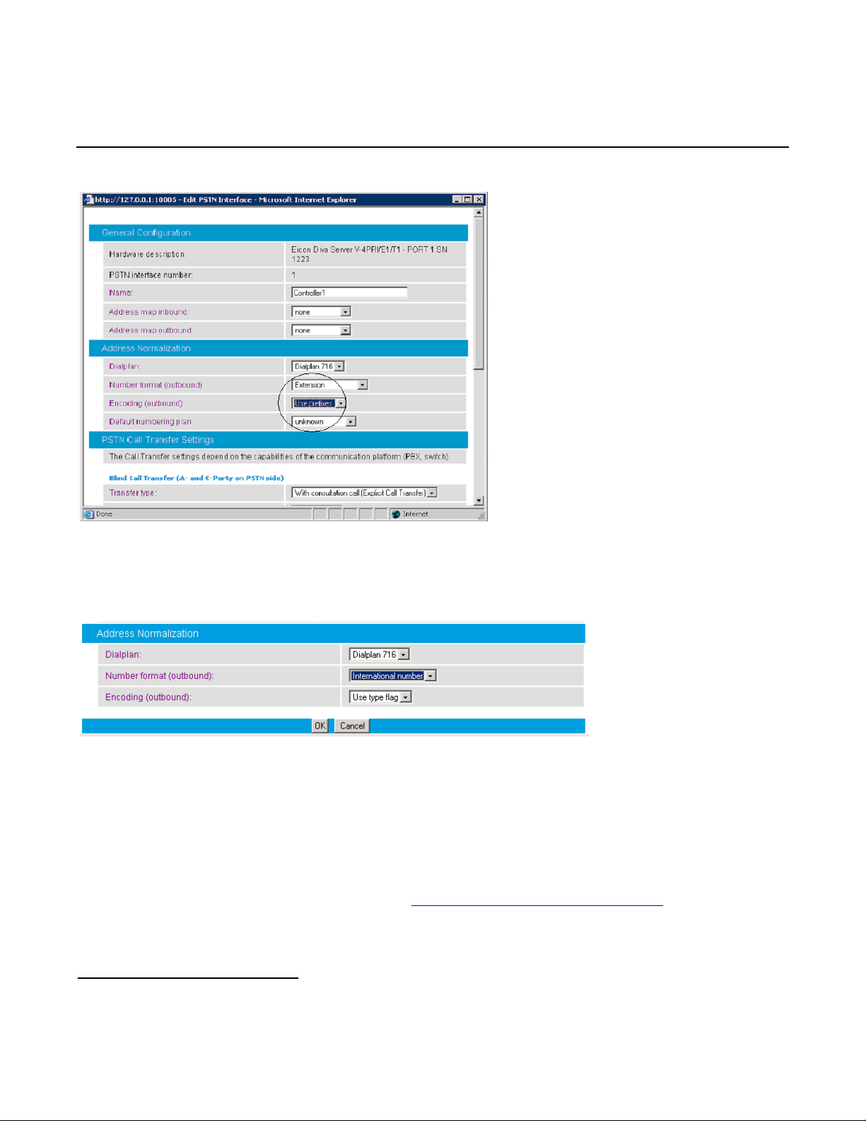
For the dialplan to be applied to outbound calls, click the Details button of the PSTN controller and configure
the Address Normalization settings as shown in the screen below. This converts the dialed numbers into
the format based on the dialplan for the PBX. If the dialed number is for an internal user, it is converted into a 4digit extension. If the called number is for a national call, 91 is prepended. Click OK on this page, and Save on
the next page for the changes to take effect.
9
Page 10
Mitel SX-2000 Lightware
For the dialplan to be applied to inbound calls, click the Details button of the configured SIP peer and
configure the Address Normalization settings as in the screen below. This converts the phone number into
the E.164 format as needed by Microsoft
®
Office Communications Server 2007. Click OK on this page, and Save
on the next page for the changes to take effect.
5.2.4.2 Address Map Configuration Example
If the dialplan does not meet your setups special requirements, the Address Map Configuration can be
used. An address map entry uses regular expressions (RegEx) (so does Microsoft
Server 2007) for converting the call address format for inbound or/and outbound direction.
Important note before applying regular expression rules in address maps: The call address for outbound calls (IP
to TDM) includes a “@hostname” part. For example, [email protected]
not just +17166391234. For inbound calls (TDM to IP), the call address is the called or calling number, with a
possible prefix “+”, “N”, or “S”. For example, an inbound call has called number 1234 with ISDN type of
numbering flag set to Subscriber, and the calling number 49715233334444 with ISDN type of numbering flag
set to International. The called address will be S1234 and the calling address will be +49715233334444.
10
®
Office Communications
is the call address,
Page 11
Dialogic® 4000 Media Gateway Series Integration Note
®
®
If the ISDN type of numbering flag is set to National, the prefix “N” will be used with the call number. If the type
is Unknown, no prefix is used.
Outbound call example using address maps:
Microsoft
®
Office Communications Server 2007 sends the E.164 dial number format to the SIP gateway. Both
called and calling numbers need to be converted into a format that the PBX can accept. If the same PBX
dialplan as in the previous section is used, the following conversions are needed.
Calling number From Microsoft
OCS To PBX
Internal +1716639xxxx 716639xxxx
Called number From Microsoft
OCS To PBX
To Internal +1716639xxxx xxxx
To National +1xxxxxxxxxx 91xxxxxxxxxx
To International +xxx…xxx +xxx…xxx
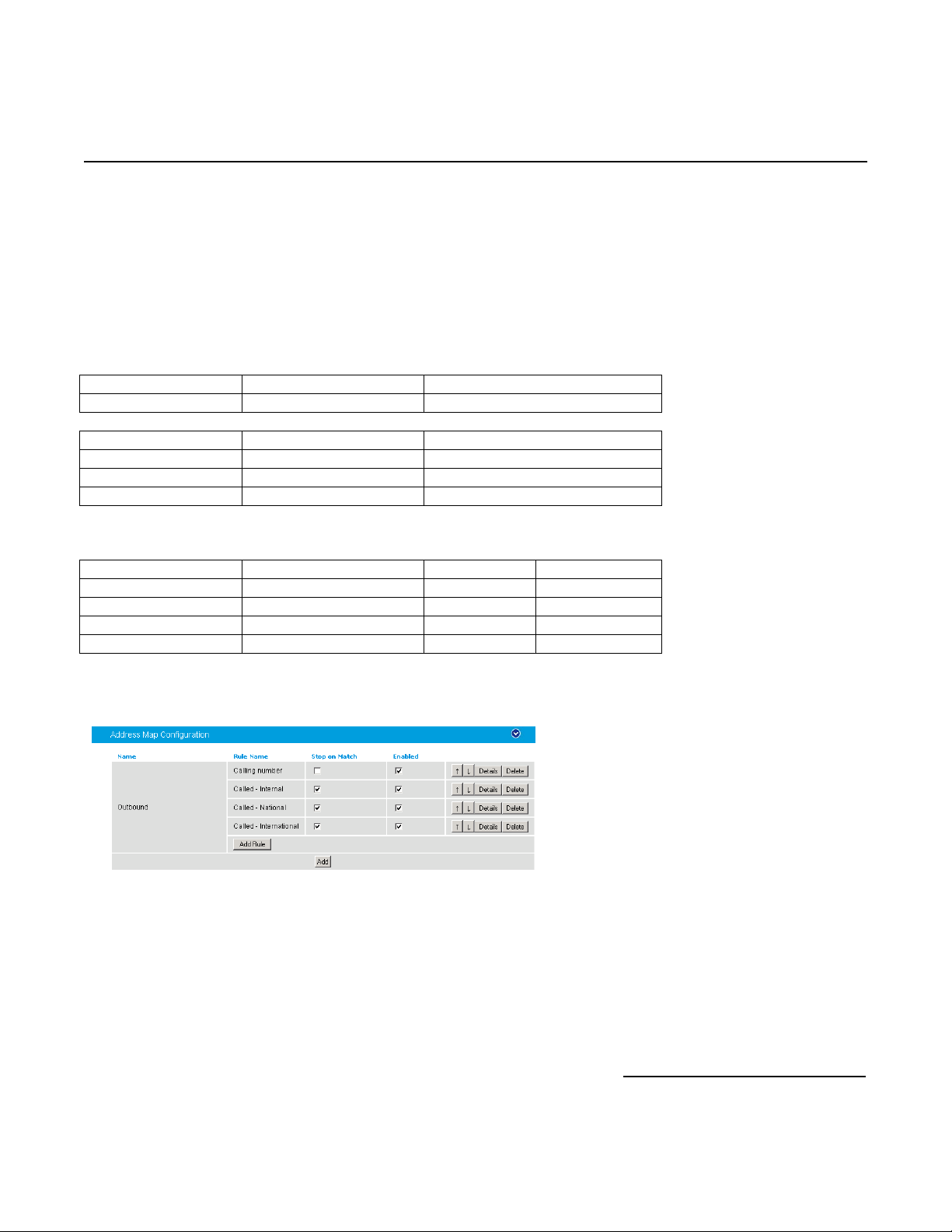
Below is RegEx for the conversion tables above.
Sub rule name Expression Format Stop on match
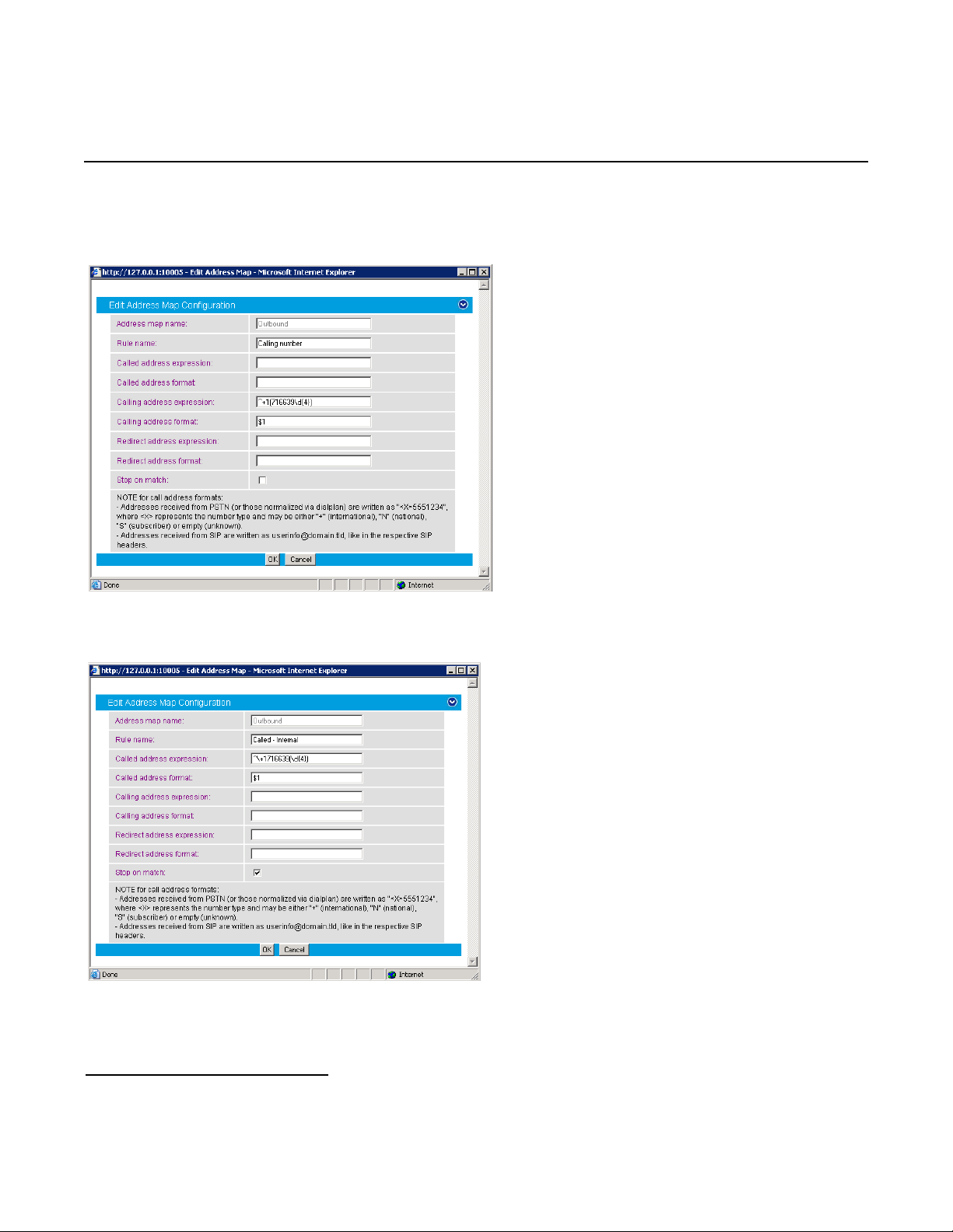
Calling number ^\+1(716639\d{4}) $1 Not checked
Called - Internal ^\+1716639(\d{4}) $1 Checked
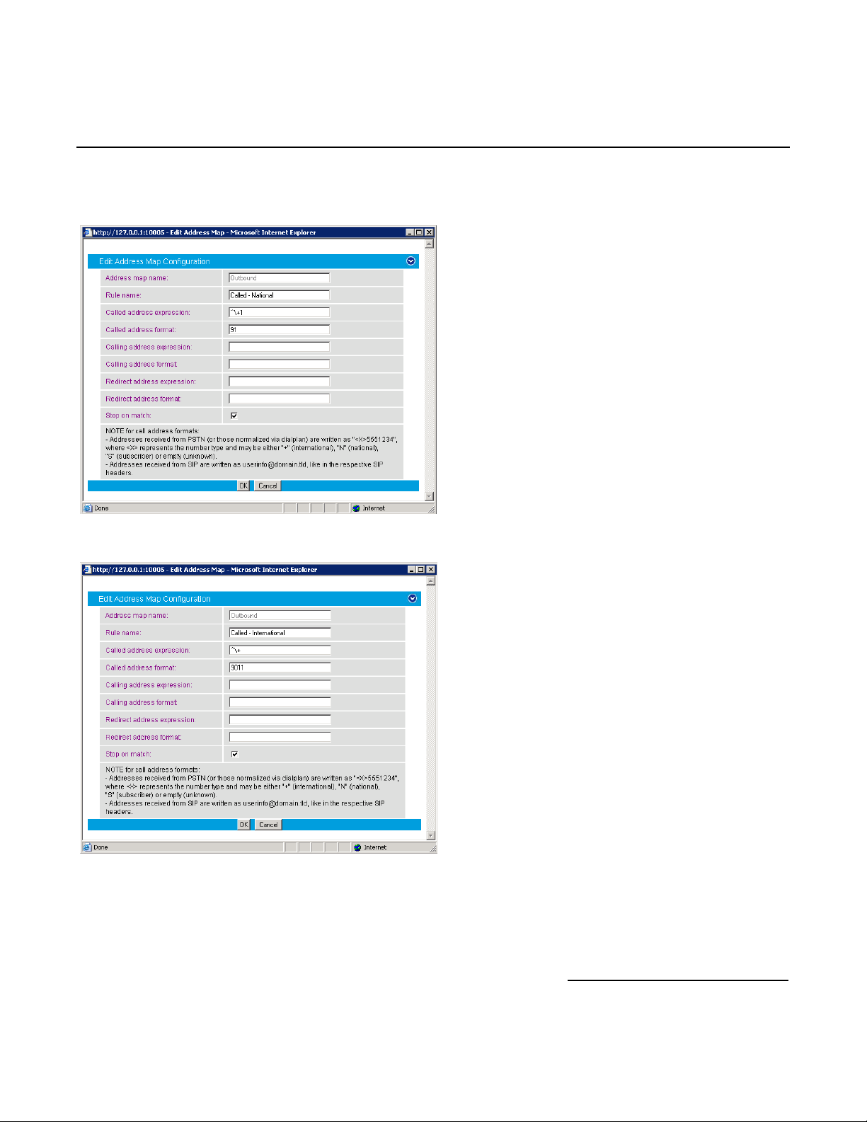
Called - National ^\+1 91 Checked
Called - International ^\+ 9011 Checked
Below are the configured address maps for outbound calls. The order of the below four sub rules and the stop
on match check mark are relevant:
11
Page 12
Mitel SX-2000 Lightware
The following screen shows the first sub rule that converts the E.164 calling number into a
10-digit national number:
The following screen shows the second sub rule that converts E.164 for the internal called number into a 4-digit
extension:
12
Page 13
Dialogic® 4000 Media Gateway Series Integration Note
The following sub rule converts the E.164 national number into a 10-digit national number with prefix 91:
The following example converts international call numbers:
13
Page 14
Mitel SX-2000 Lightware
®
®
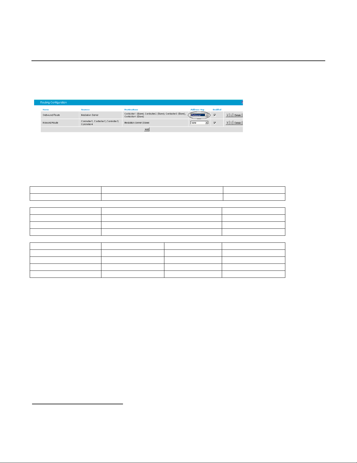
Once an address map rule is created, it can be applied in three different places. To ease the configuration and
troubleshooting processes, apply the rule on the outbound route as shown below:
Inbound call example using address map:
This example assumes that the PBX sends inbound calls using a 4-digit extension, with the ISDN type of number
flag set to Subscriber for internal numbers, National for national calls, and International for
international calls.
Called number From PBX To Microsoft
OCS
Internal xxxx (with subscriber type of number) +1716639xxxx
Calling number From PBX To Microsoft
OCS
Calling from internal xxxx (with subscriber type of number) +1716639xxxx
Calling from national xxxxxxxxxx (with national type of number) +1xxxxxxxxxx
Calling from international xxx…xxx (with international type of number) +xxx…xxx
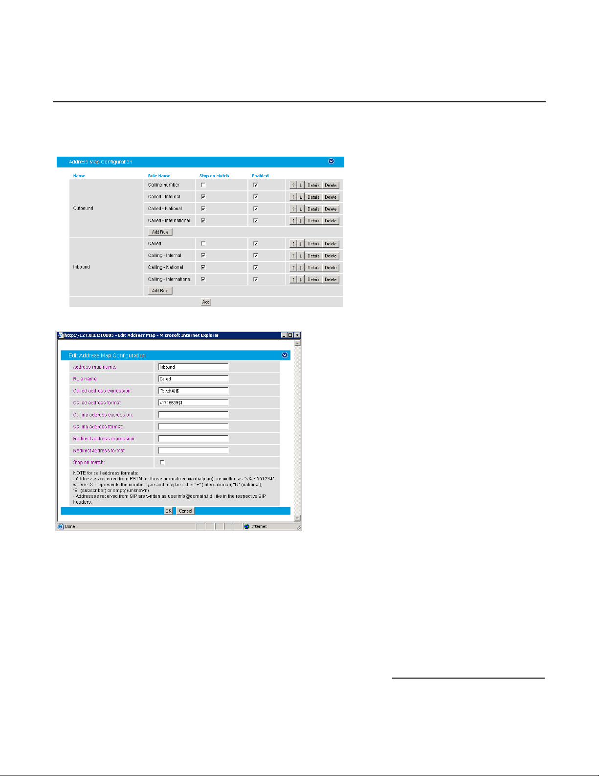
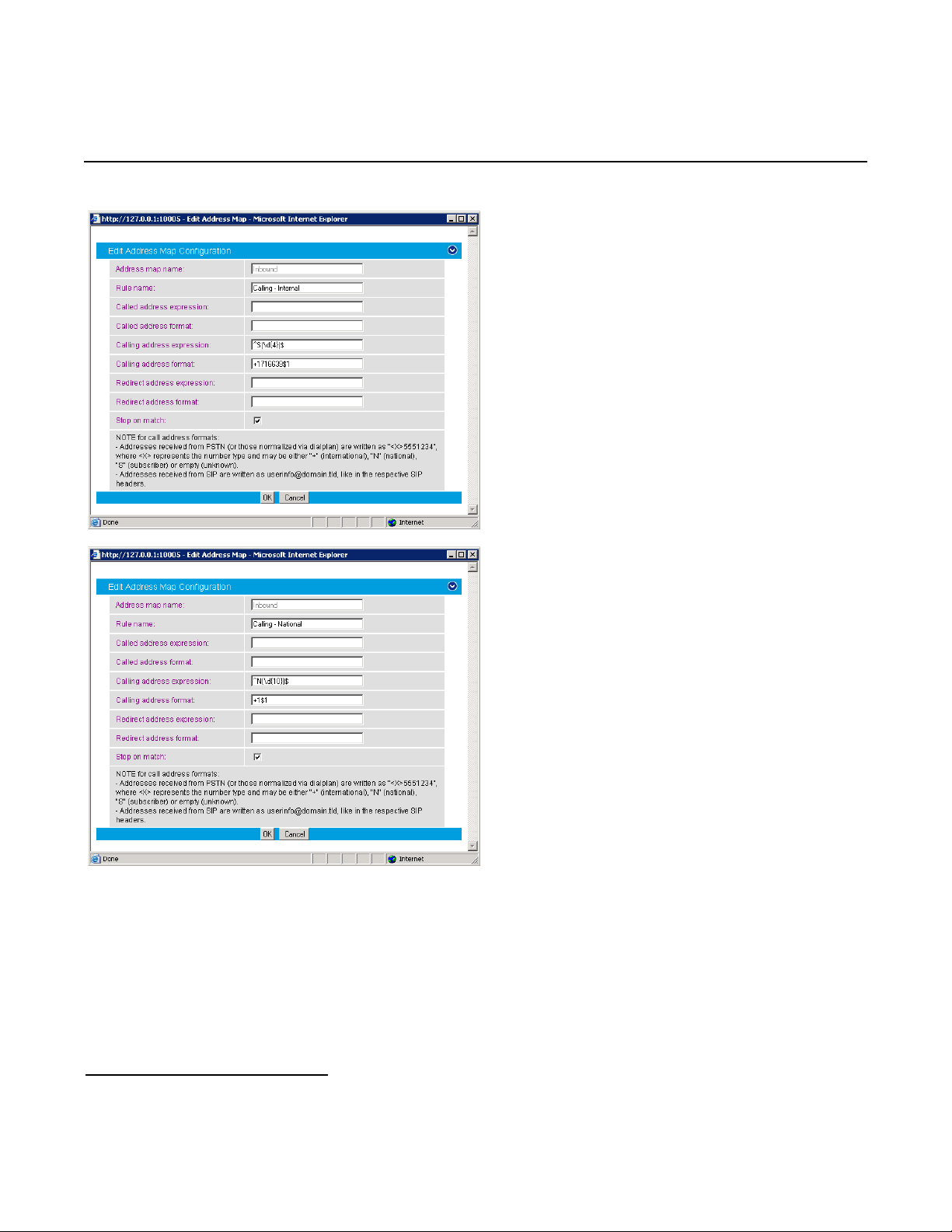
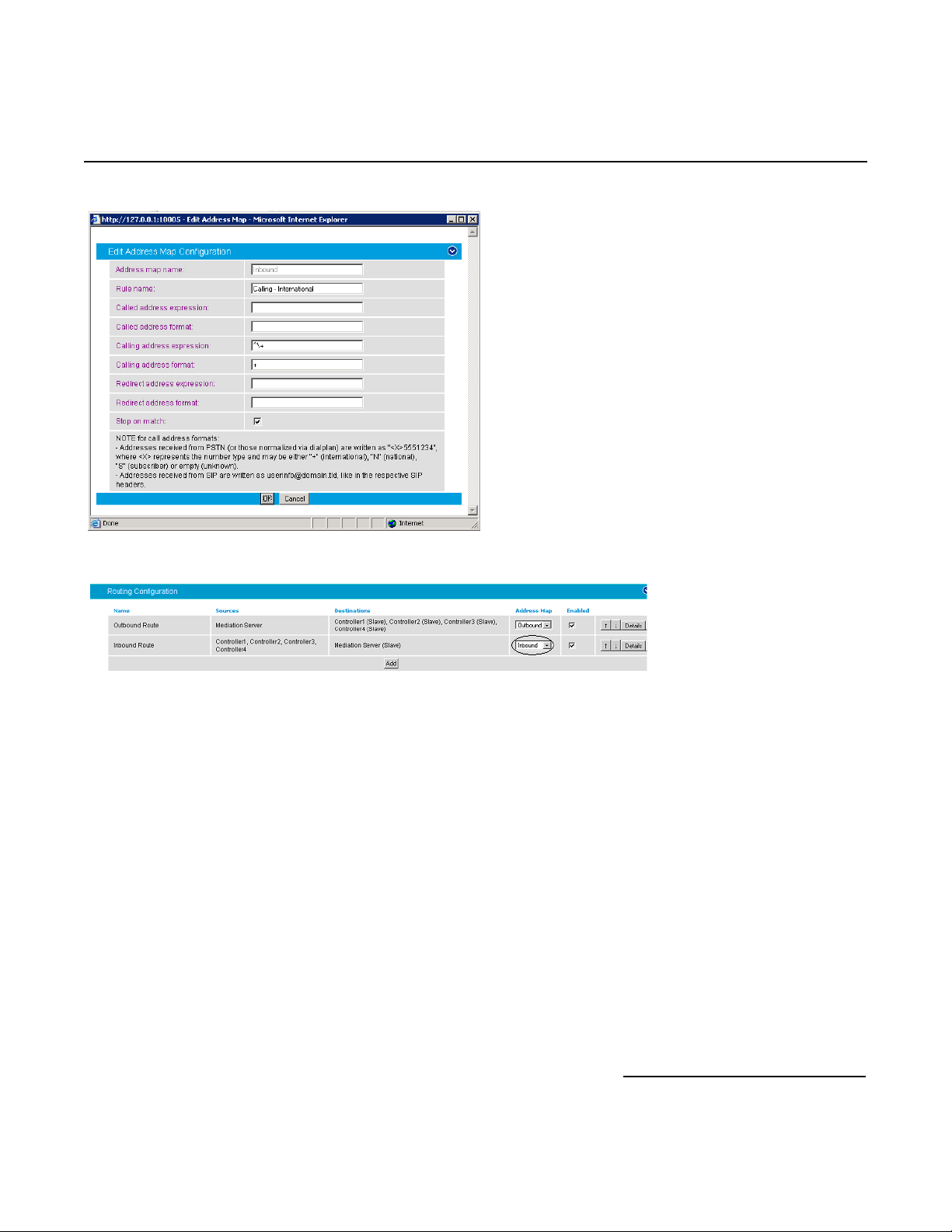
Sub rule name Expression Format Stop on match
Called ^S(\d{4})$ +1716639$1 Not checked
Calling - internal ^S(\d{4})$ +1716639$1 Checked
Calling - national ^N(\d{10})$ +1$1 Checked
Calling - international ^\+ + Checked
14
Page 15
Dialogic® 4000 Media Gateway Series Integration Note
Create an address map named Inbound and its four sub rules as shown below:
15
Page 16
Mitel SX-2000 Lightware
16
Page 17
Dialogic® 4000 Media Gateway Series Integration Note
Apply the address map inbound rule on the inbound route as follows:
5.2.5 Restarting the Dialogic® Diva® SIPcontrol™ Software
Note: A restart of the Diva SIPcontrol software service is needed only if the setting under Network Interface
is changed.
Save the configuration and restart the Diva SIPcontrol software service for the changes to take effect. To do so,
click Service Status on the left hand side of the main configuration page, and then click Restart
SIPcontrol. The Last operation log will show that the service has been stopped and started again.
17
Page 18

Mitel SX-2000 Lightware
6. PBX Setup Notes
6.1 Mitel SX-2000 Lightware
This section provides information about the Dialogic® 4000 Media Gateway Series PBX administration
requirements for Mitel SX-2000 Light systems. This information includes:
1. T1 Interface Administration
2. Configure the Mitel SX-2000 Light for the T1 Q.SIG protocol
3. Program Automatic Route Selection
4. Configure T1 protocol on NSU
Note: This document was developed using the Mitel SX-2000 Light system with the following software versions
and MOSS Options:
1. SX-2000 Lightware Version 34.2.0.20
2. IMAT Version 7.5.1.4
3. MOSS Sheet Options:
Description Option Number
Message Center 31
MSAN/APNSS 37
MSDN/DPNSS Data 38
MSDN/DPNSS Public Net Access 39
MSDN/DPNSS Voice I 41
MSDN/DPNSS Voice II 42
MSDN/DPNSS Voice III 43
MSDN/DPNSS Voice IV 44
MSDN/DPNSS Voice V 45
MSDN/DPNSS Voice VI 46
QSIG 57
T1/D4 64
Notes:
• Other software versions may not support certain features specified in this section.
• The terms “Select” and “Set” are used to imply the respective actions of using the arrow keys to highlight the
specified choice and of typing in the specified value.
• The installation of the T1 board must be validated prior to this configuration. Sometimes this can only be
done by the switch vendor depending on the administration access capability.
18
Page 19

Dialogic® 4000 Media Gateway Series Integration Note
6.1.1 T1 Interface Administration
There are three types of T1 interface administration required to properly program the Q.SIG integration on the
Mitel SX-2000 Light system for the Dialogic
• SX-2000 Light Administration,
• Automatic Route Selection (ARS), and
• NSU Configurations / IMAT Programming.
6.1.1.1 SX-2000 Light Administration
Step 1: Log into the Mitel SX-2000 Light system.
®
4000 Media Gateway Series:
Press [ESC] then [7] to access the Customer Data Entry menu.
19
Page 20

Mitel SX-2000 Lightware
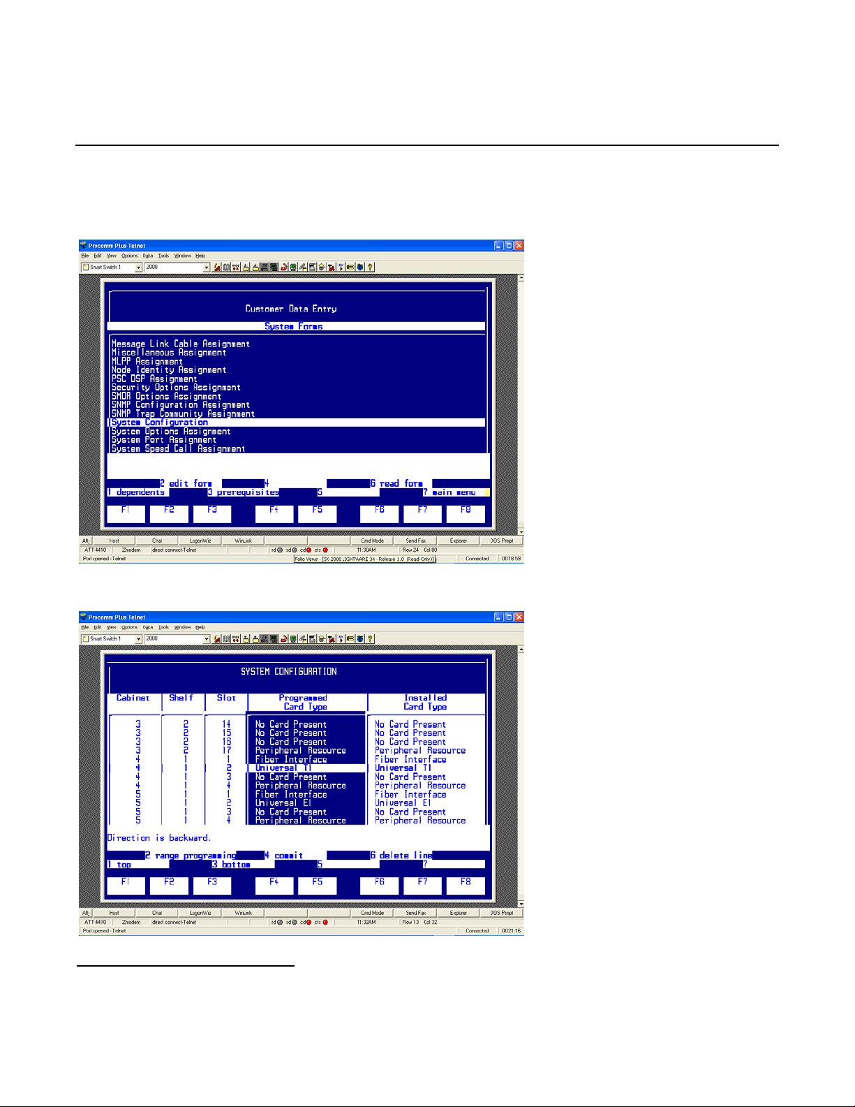
Select System Forms and press [ESC] then [1] to access the System Forms menu.
Step 2: In the System Forms menu, select Dimension and Feature Select and press [ESC] then [2] to
edit the Dimension and Feature Selection form.
20
Page 21

Configure the Dimension and Feature Selection as follows:
Dialogic® 4000 Media Gateway Series Integration Note
Notes:
• Parameters not listed below can be left at their default settings.
• Q.SIG is a purchased option, so please verify that you have purchased Q.SIG before you continue.
• Select Q-SIG, set it to Yes, and press [ENTER].
• Press [ESC] then [4] to commit to changes and [ESC] then [1] to confirm the changes.
• Press [ESC] then [Q] to return to the System Forms menu.
21
Page 22
Mitel SX-2000 Lightware
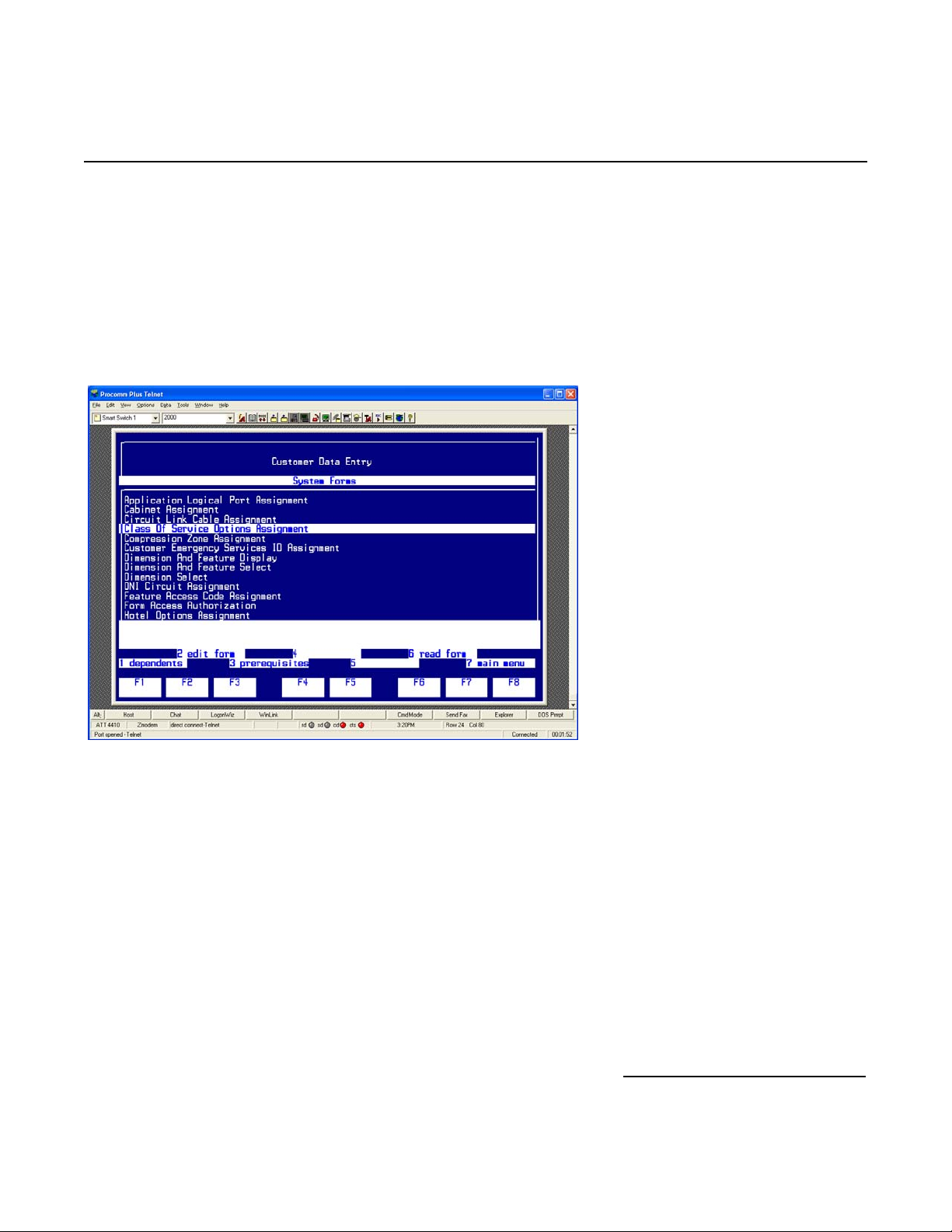
Step 3: In the System Forms menu, select System Configuration and press [ESC] then [2] to edit the
System Configuration form.
Configure the form as follows:
22
Page 23
Dialogic® 4000 Media Gateway Series Integration Note
• Select the Cabinet number, the Shelf number, and the Slot number in which the T1 Q.SIG line is being
installed.
• Set Programmed Card Type to Universal T1 and press [ENTER].
• Press [ESC] then [4] to commit to changes and [ESC] then [1] to confirm the changes.
• Press [ESC] then [Q] to return to the System Forms menu.
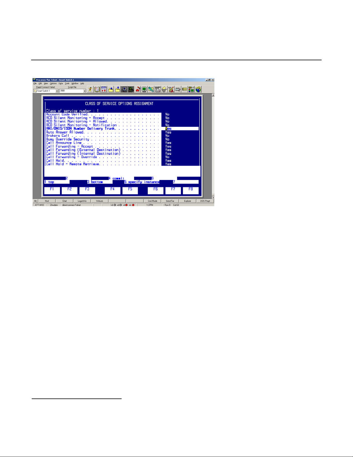
Step 4: In the System Forms menu, select Class Of Service Options Assignment and press [ESC]
then [2] to edit the Class Of Service Options Assignment form.
Configure the form as follows:
23
Page 24
Mitel SX-2000 Lightware
• Set Class of service number: to an unused class of service number.
• Press [ESC] then [1] to create the new class of service.
• Set the following parameters to Yes:
o ANI/DNIS/ISDN Number Delivery Trunk
o Call Announce Line
o Call Forwarding (External Destination)
o Display ANI/DNIS/ISDN Calling/Called Number
o Display Caller ID on Multicall/Keylines
o Handsfree Answerback Allowed
o Message Waiting – Audible Tone Notification
o Public Network Access via DPNSS
o Public Trunk
• Set Message Waiting – Deactivate on Off-Hook to No.
• Press [ESC] then [4] to commit to changes and [ESC] then [1] to confirm the changes.
• Press [ESC] then [Q] to return to the System Forms menu.
• Press [ESC] then [7] to return to the Customer Data Entry interface.
24
Page 25
Dialogic® 4000 Media Gateway Series Integration Note
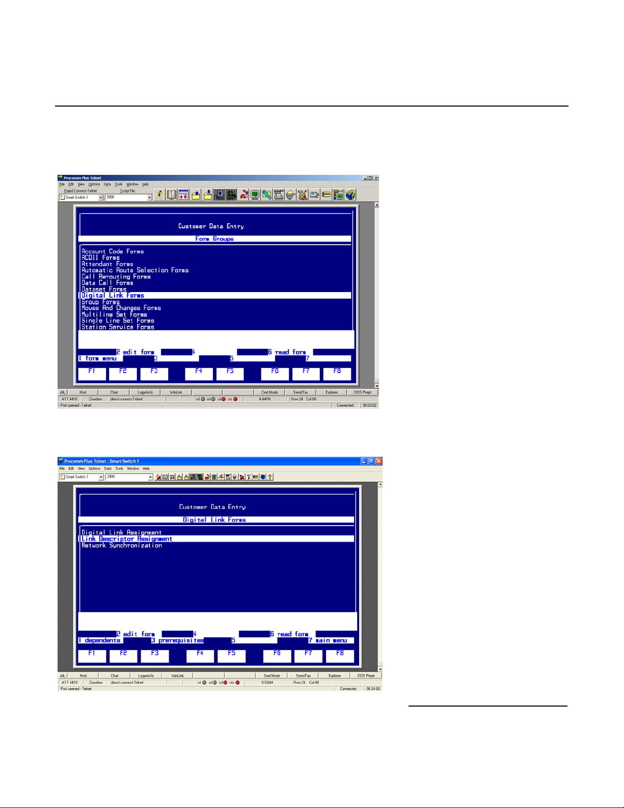
Step 5: In the Customer Data Entry menu, select Digital Link Forms and press [ESC] then [1] to
access the Digital Link Form menu.
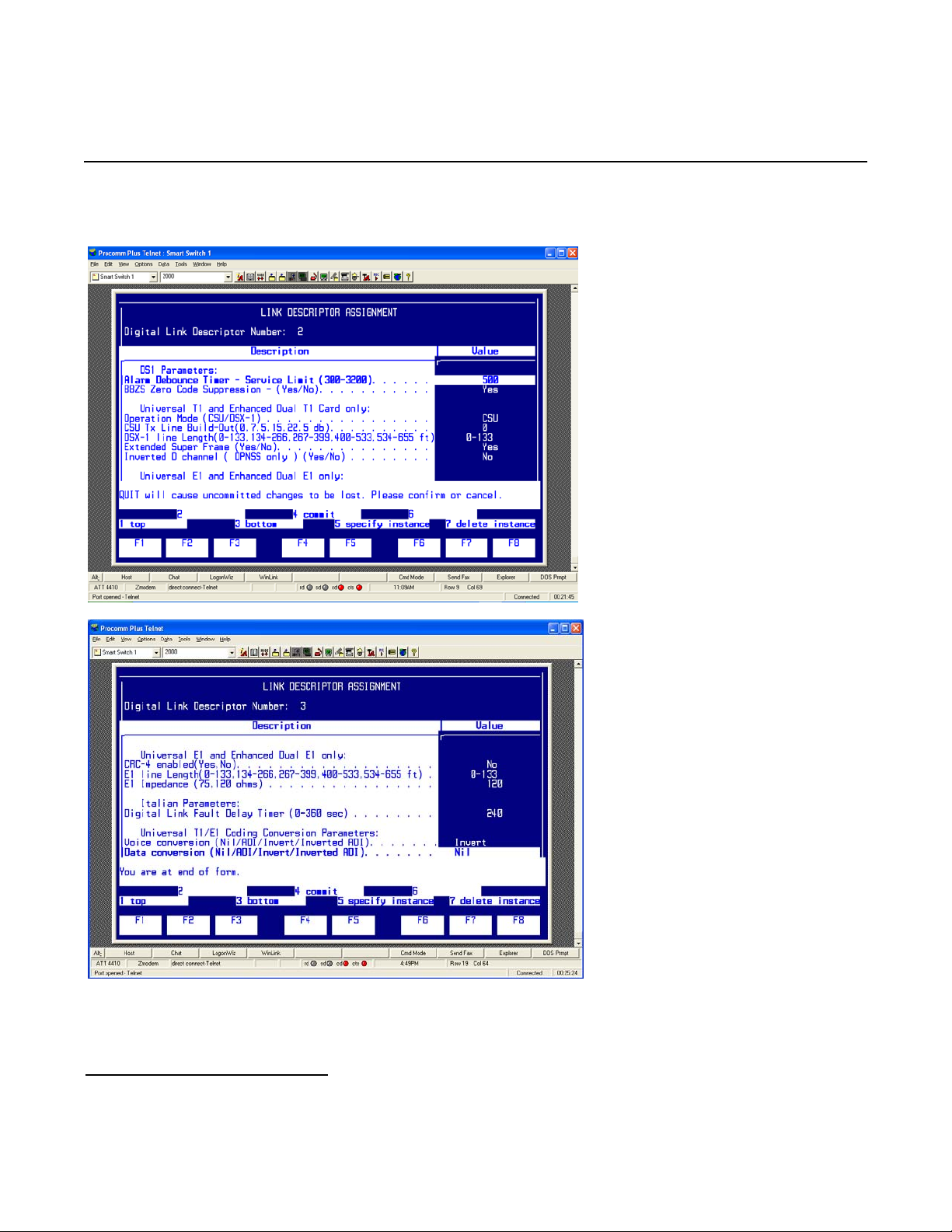
In the Digital Link Forms menu, select Link Descriptor Assignment and press [ESC]
then [1] to edit the Link Descriptor Assignment form.
25
Page 26
Mitel SX-2000 Lightware
Configure the form as follows:
Note: Parameters not listed below can be left at their default settings.
• Set Digital Link Descriptor Number to an unused digital link descriptor number.
• Set Address for Message Control to A.
26
Page 27
Dialogic® 4000 Media Gateway Series Integration Note
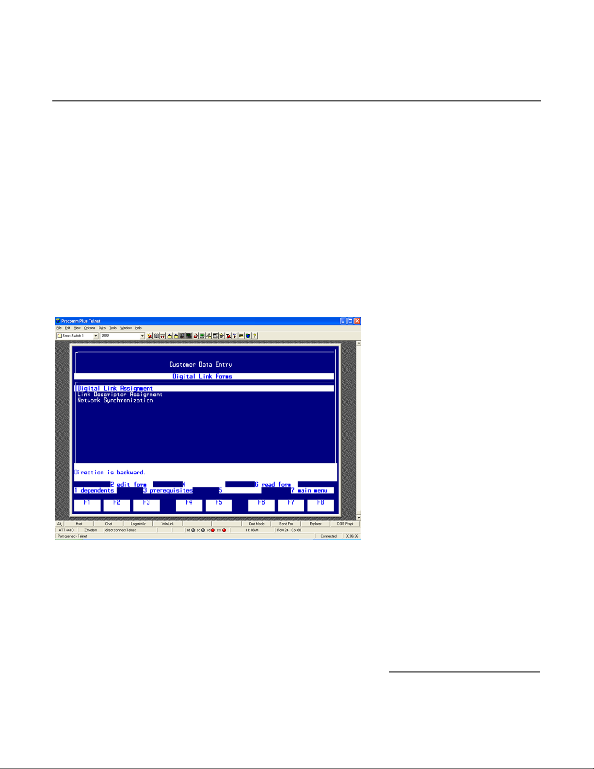
• Set Integrated Digital Access to ISDN Node.
• Set QSIG Private Network Access to Yes.
• Set Termination Mode to NT.
• Set Operation Mode to CSU.
• Set CSU Tx Line Build-Out (dB.) to 0.
• Set Extended Super Frame to Yes.
• Set Inverted D Channel to No.
• Set Voice Conversion to Invert.
• Press [ESC] then [4] to commit to changes and [ESC] then [1] to confirm the changes.
• Press [ESC] then [Q] to return to the Digital Link Forms menu.
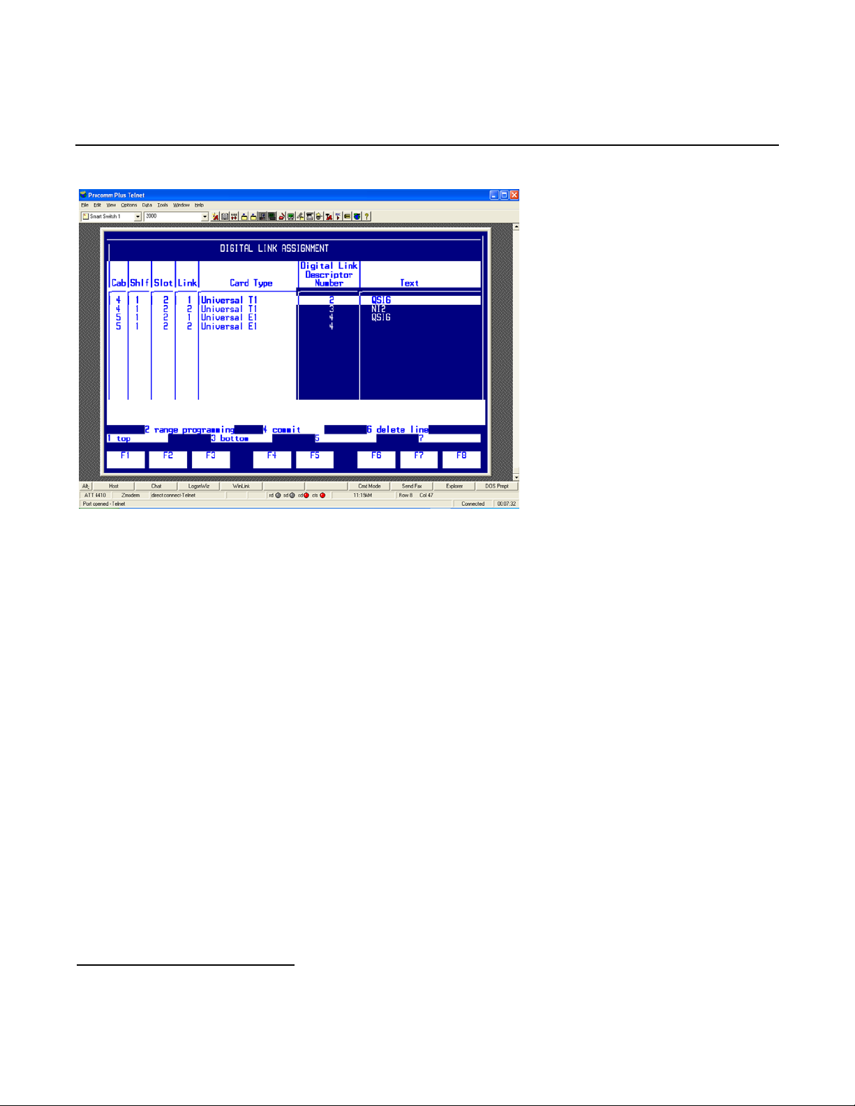
Step 6: In the Digital Link Forms menu, select Digital Link Assignment and press [ESC] then [2] to
edit the Digital Link Assignment form.
Configure the form as follows:
27
Page 28
Mitel SX-2000 Lightware
• As Link number select 1, and as Cabinet number, Shlf number, and Slot number select the numbers in
which the T1 Q.SIG line is being installed.
• Set Digital Link Descriptor Number
the SX-2000 Light Administration and press [ENTER].
• The Text field can be left blank or a description of the link can be entered.
• Press [ESC] then [4] to commit to changes and [ESC] then [1] to confirm the changes.
• Press [ESC] then [Q] to return to the Digital Link Forms menu.
• Press [ESC] then [7] to return to the Customer Data Entry interface.
to the link descriptor assignment number defined in Step 5 of
28
Page 29
Dialogic® 4000 Media Gateway Series Integration Note
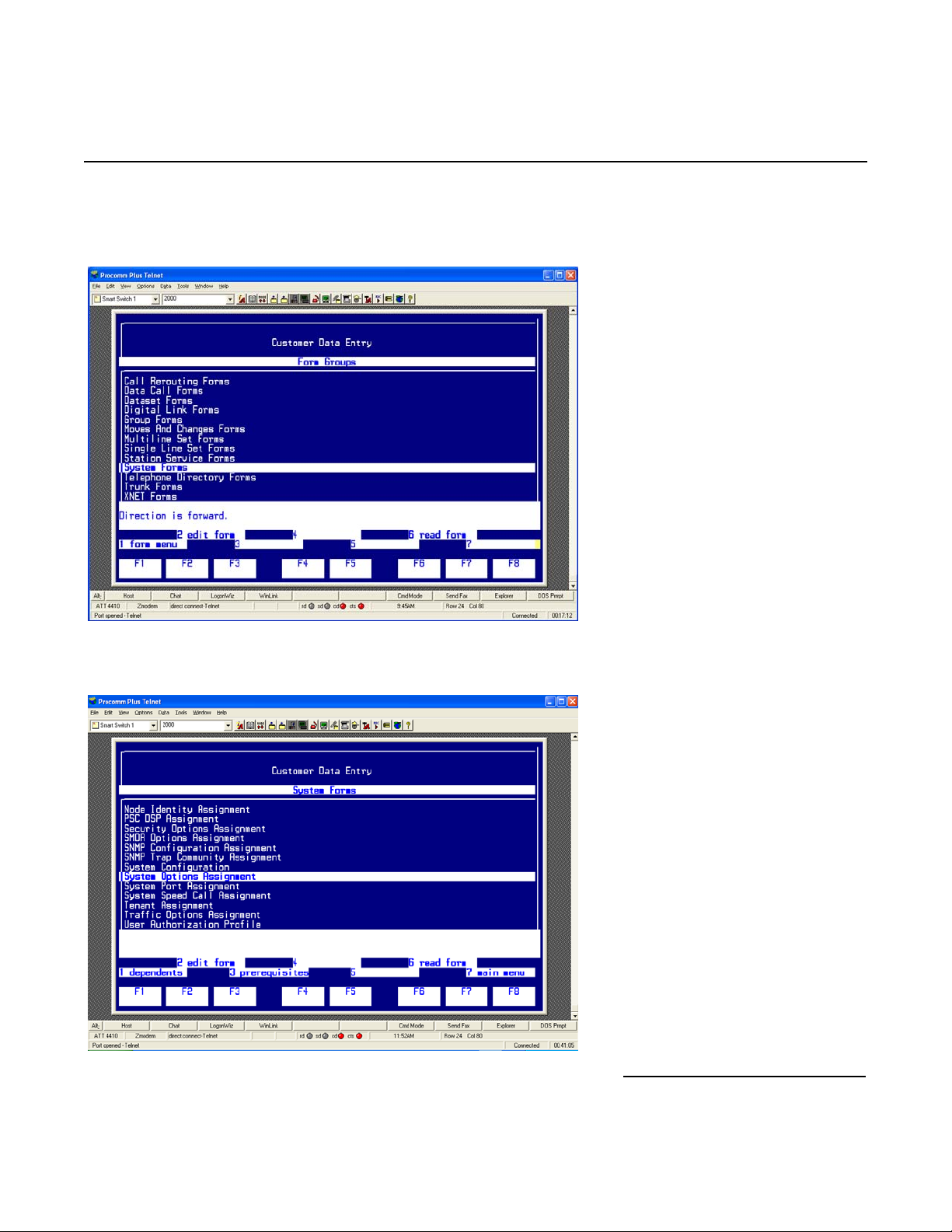
Step 7: In the Customer Data Entry menu, select System Forms and press [ESC] then [2] to access the
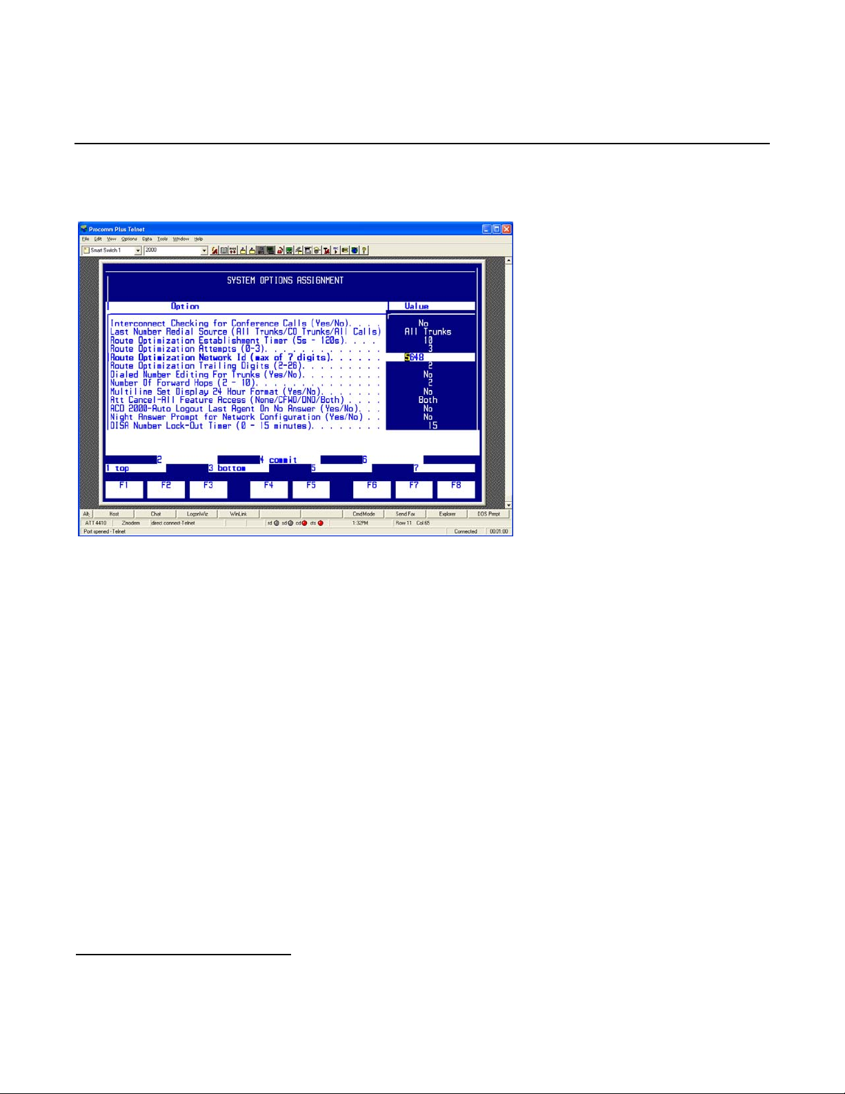
System Forms menu.
In the System Forms menu, select System Options Assignment and press [ESC] then [2]
to edit the System Options Assignment form.
29
Page 30
Mitel SX-2000 Lightware
Configure the form as follows:
Note: Parameters not listed below can be left at their default settings.
• Set Route Optimization Network Id to a string of digits that needs to have the same length as the
phone extension, and press [ENTER].
• Press [ESC] then [4] to commit to changes and [ESC] then [1] to confirm the changes.
• Press [ESC] then [Q] to return to the System Forms menu.
• Press [ESC] then [7] to return to the Customer Data Entry interface
30
Page 31
Dialogic® 4000 Media Gateway Series Integration Note
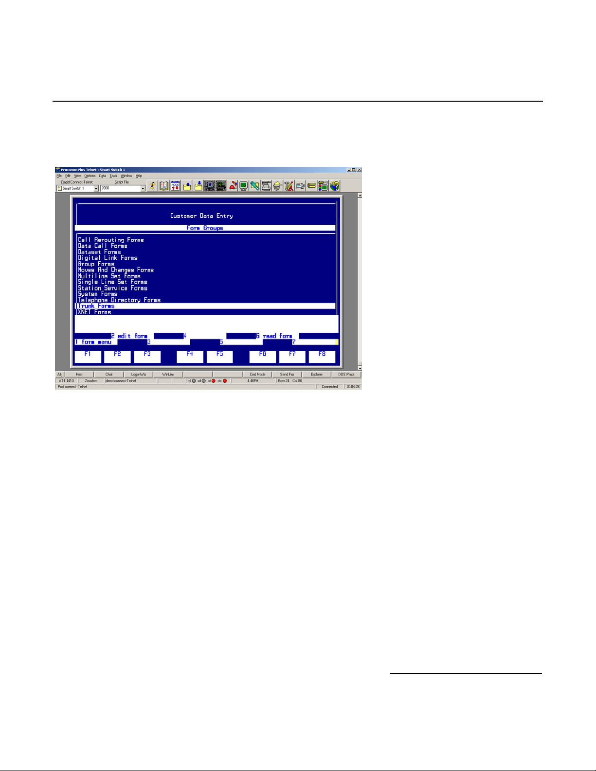
Step 8: In the Customer Data Entry menu, select Trunk Forms and press [ESC] then [1] to access the
Trunk Forms menu.
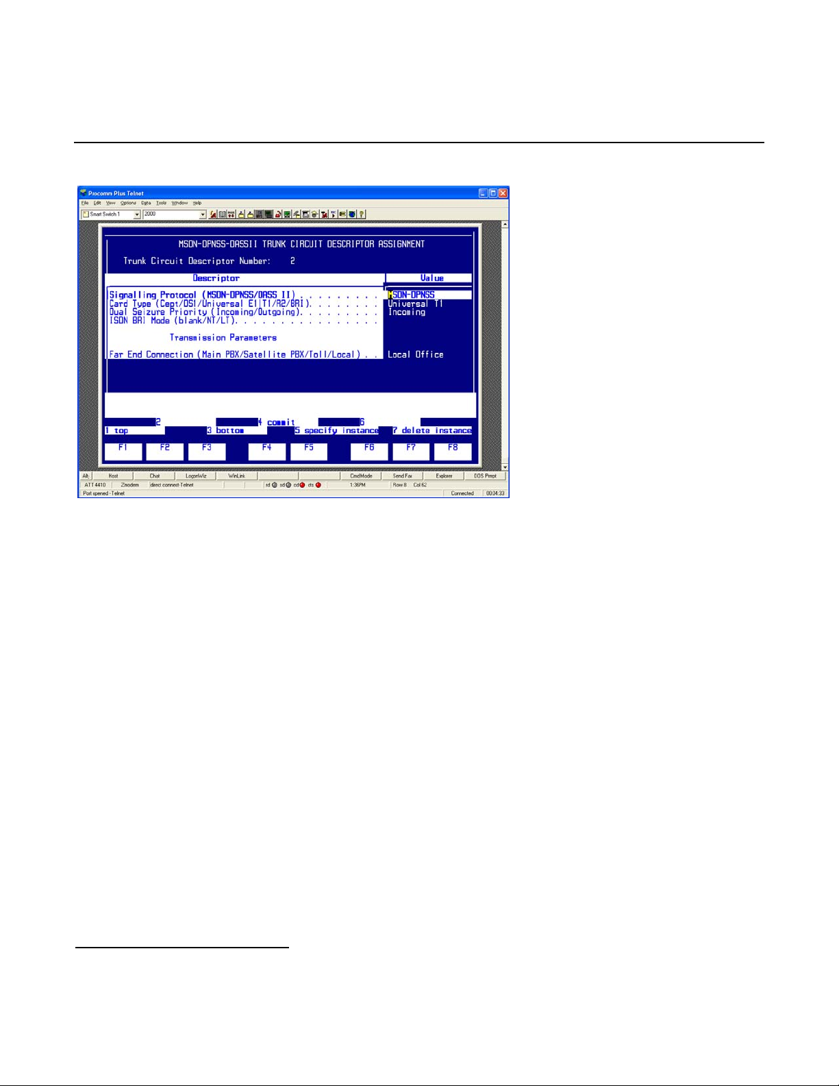
In the Trunk Forms menu, select MSDN-DPNSS-DASSII Trunk Circuit Descriptor Assignment and
press [ESC] then [2] to edit the MSDN-DPNSS-DASSII Trunk Circuit Descriptor Assignment form.
Configure the form as follows:
31
Page 32
Mitel SX-2000 Lightware
Note: Parameters not listed below can be left at their default settings.
• Set Trunk Circuit Descriptor Number to an unused trunk circuit descriptor number.
• Set Signaling Protocol to MSDN-DPNSS.
• Set Dual Seizure Priority to Incoming.
• Set Far End Connection to Local Office.
• Set Card Type to Universal T1.
• Press [ESC] then [4] to commit to changes and [ESC] then [1] to confirm the changes.
• Press [ESC] then [Q] to return to the Trunk Forms menu.
32
Page 33
Dialogic® 4000 Media Gateway Series Integration Note
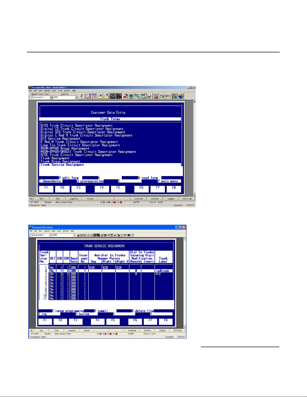
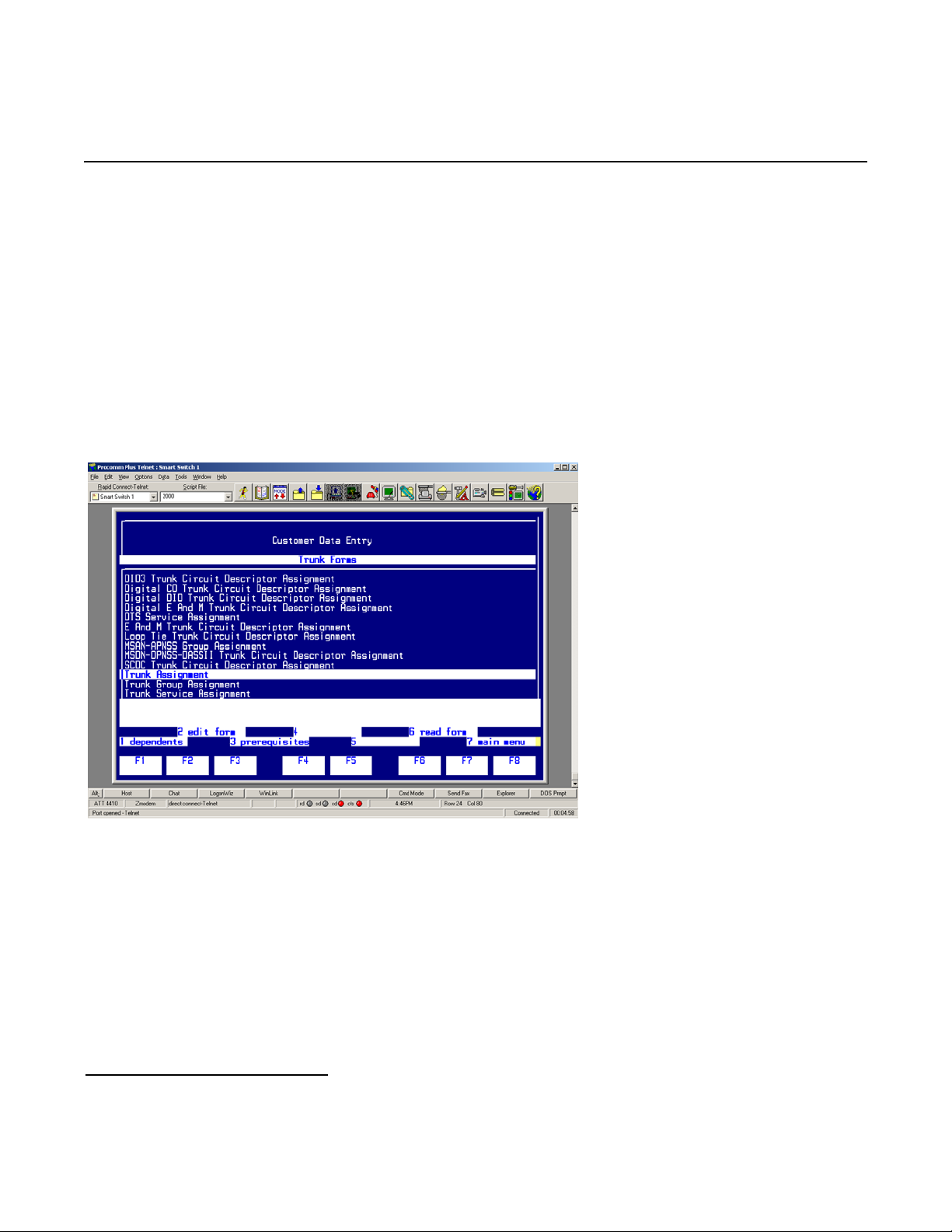
Step 9: In the Trunk Forms menu, select Trunk Service Assignment and press [ESC] then [2] to edit the
Trunk Service Assignment form.
Configure the form as follows:
33
Page 34
Mitel SX-2000 Lightware
Note: Parameters not listed below can be left at their default settings.
• Select an unused Trunk Service No.
• Set COS (Class of Service) to the class of service number defined in Step 4 of the SX-2000 Light
Administration.
• Set COR (Class of Restriction) to a valid class of restriction number.
• Set Absorb to 0.
• Press [ESC] then [4] to commit to changes and [ESC] then [1] to confirm the changes.
• Press [ESC] then [Q] to return to the Trunk Forms menu.
Step 10: In the Trunk Forms menu, select Trunk Assignment and press [ESC] then [2] to edit the Trunk
Assignment form.
34
Page 35
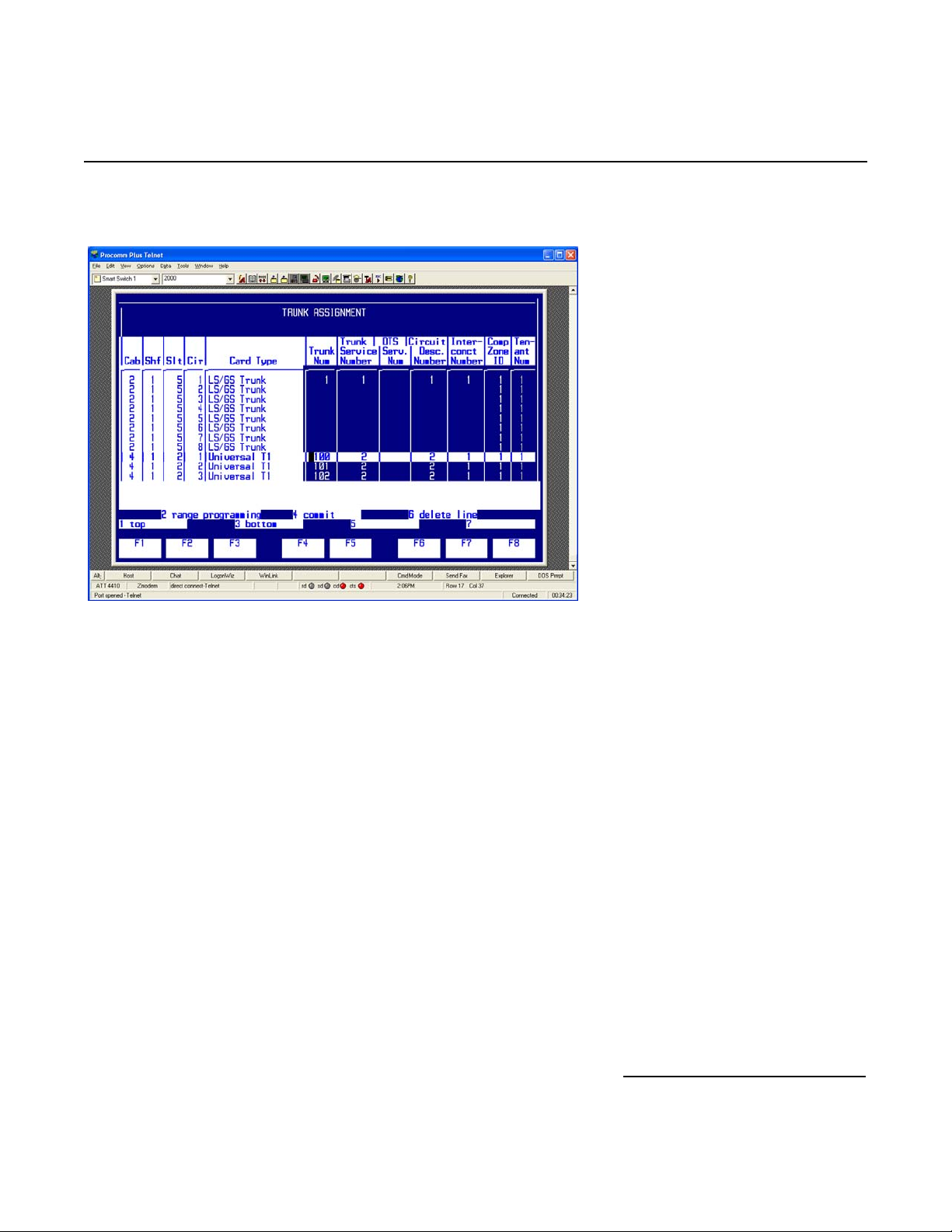
Configure the form as follows:
Dialogic® 4000 Media Gateway Series Integration Note
Note: Parameters not listed below can be left at their default settings.
• Select as Circuit number 1, and as Cabinet number, Shelf number, and Slot number the number in which the
T1 QSIG line is being installed.
• Set Trunk Num to an unused trunk number that has at least 22 unused trunk numbers available after it
(e.g., if you select 100, 101-122 must also be available).
• Set Trunk Service Number to the trunk service number defined in Step 9 of SX-2000 Light
Administration.
• Set Circuit Desc. Number to the circuit descriptor number defined in Step 8 of the SX-2000 Light
Administration.
• Set Interconnect Number to a valid interconnect number.
• Press [ESC] then [2] to define the range programming, a RANGE PROGRAMMING Parameters data entry
field will appear in the main screen.
• Set Trunk Num to the trunk number defined earlier in this step, and press [TAB].
• Set the Trunk Service Number to 0, and press [TAB].
• Set Circuit Desc. Number to 0, and press [TAB].
• Set Interconnect Number to 0, and press [TAB].
• Set Comp Zone IO to 0, and press [TAB].
• Set Tenant Number to 0, and press [TAB].
• Press [ESC] then [2] to define the range programming, a Specify number of lines data entry field will
appear in the main screen.
• Set Specify number of lines to 22 and press [ENTER]
• Press [ESC] then [4] to execute the command.
35
Page 36
Mitel SX-2000 Lightware
• Press [ESC] then [4] to commit to changes and [ESC] then [1] to confirm the changes.
• Press [ESC] then [Q] to return to the Trunk Forms menu.
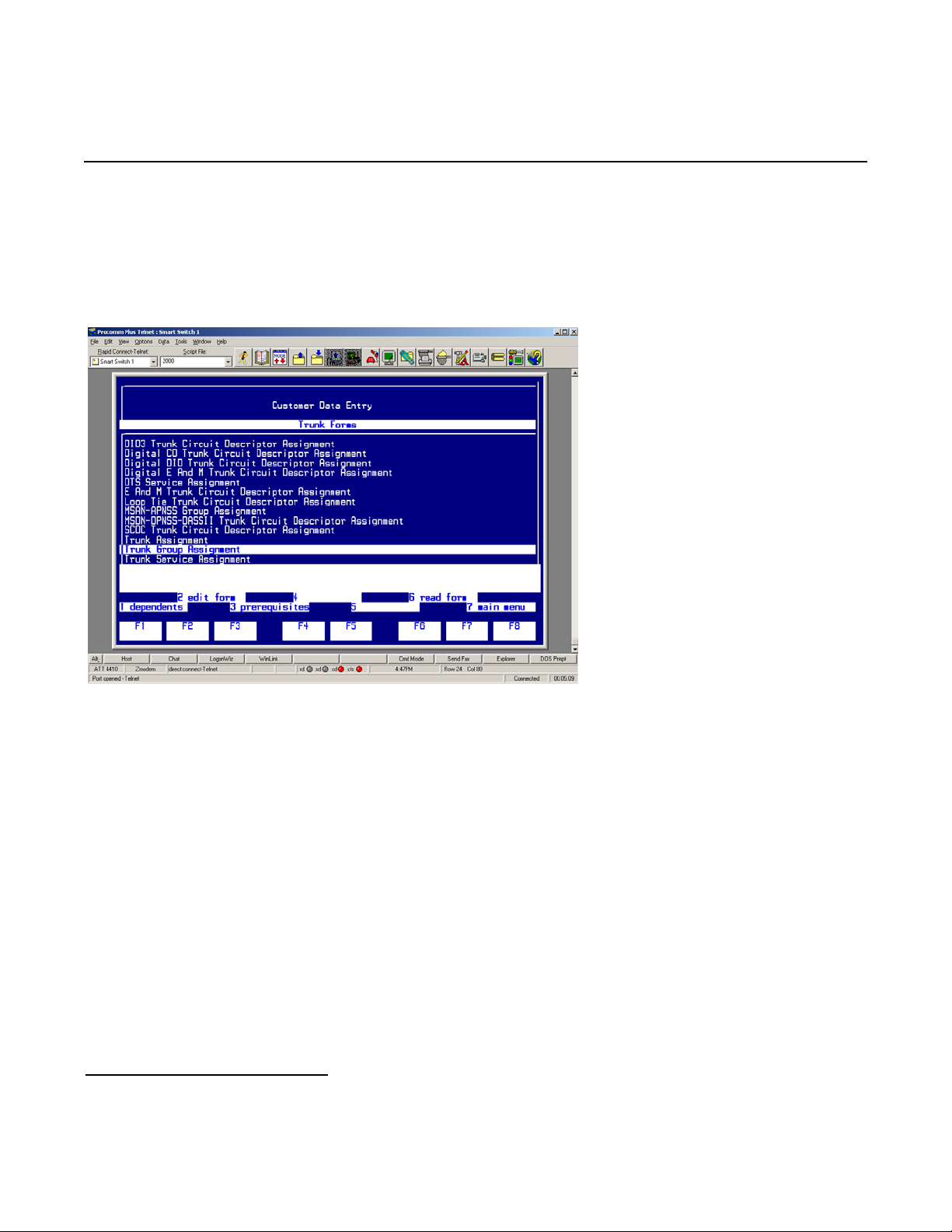
Step 11: In the Trunk Forms menu, select Trunk Group Assignment and press [ESC] then [2] to edit the
Trunk Group Assignment form.
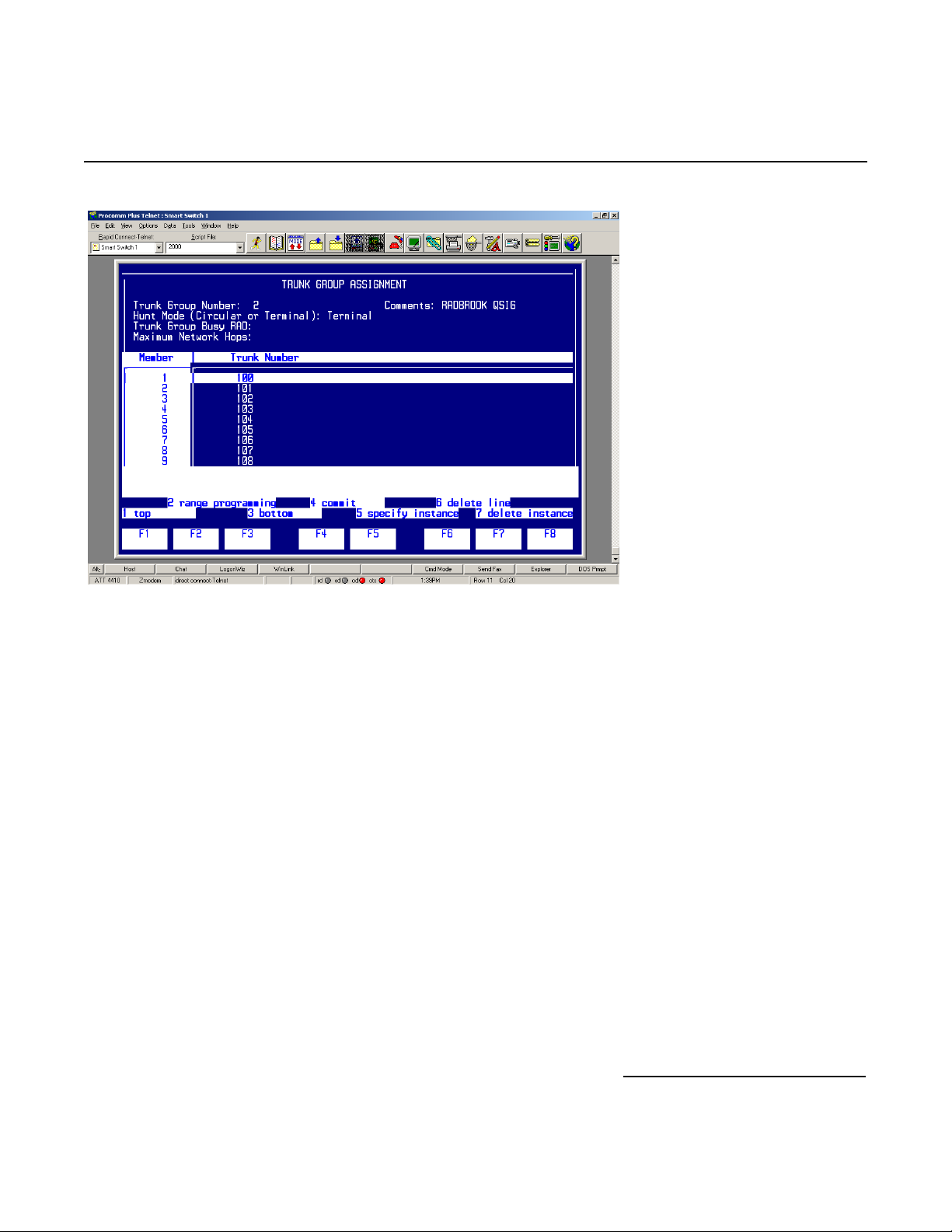
Configure the form as follows:
36
Page 37
Dialogic® 4000 Media Gateway Series Integration Note
Note: Parameters not listed below can be left at their default settings.
• Set Trunk Group Number to an unused trunk group number.
• Set Hunt Mode to Terminal.
• Press [ESC] then [1] to recall a list of members.
• Set Member # 1 to the first trunk number defined in Step 10 of the SX-2000 Light Administration.
• Press [ESC] then [2] to define the range programming, RANGE PROGRAMMING Parameters data entry field
will appear in the main screen.
• Set Trunk Number to 1, and press [ESC] then [2].
• Set Specify number of lines to 22 and press [ENTER].
• Press [ESC] then [4] to execute the command.
• Press [ESC] then [4] to commit to changes and [ESC] then [1] to confirm the changes.
• Press [ESC] then [Q] to return to the Trunk Forms menu.
• Press [ESC] then [7] to return to the Customer Data Entry interface.
37
Page 38
Mitel SX-2000 Lightware
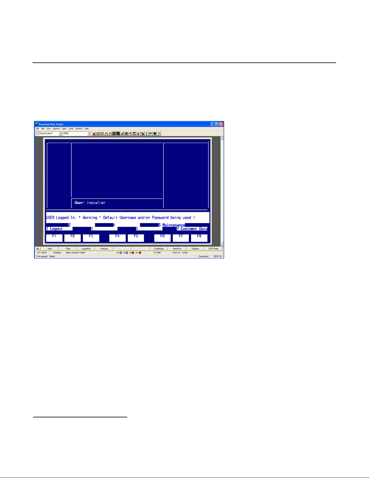
6.1.1.2 Automatic Route Selection (ARS)
Step 1: Log into the Mitel SX-2000 Light system.
Press [ESC] then [7] to access the Customer Data Entry menu.
38
Page 39
Dialogic® 4000 Media Gateway Series Integration Note
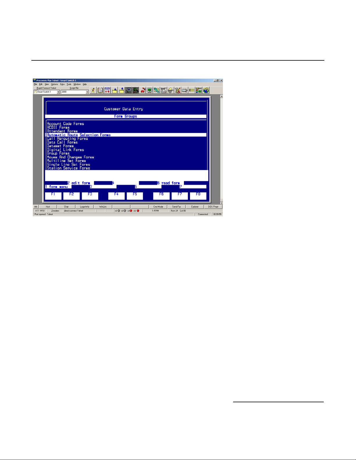
Select Automatic Route Selection Forms and press [ESC] then [1] to access the ARS Forms menu.
39
Page 40
Mitel SX-2000 Lightware
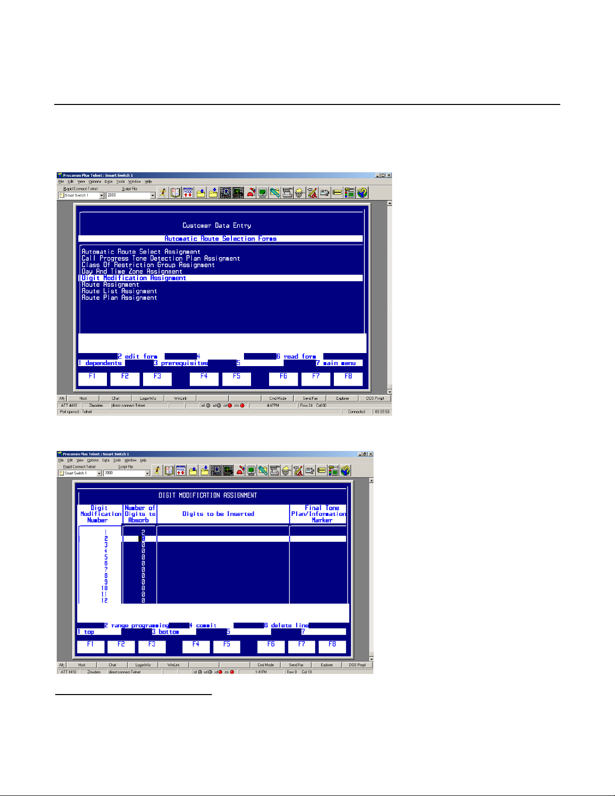
Step 2: In the ARS menu, select Digital Modification Assignment and press [ESC] then [2] to edit the
Digital Modification Assignment form.
Configure the Digital Modification Assignment as follows:
40
Page 41
Dialogic® 4000 Media Gateway Series Integration Note
Note: Parameters not listed below can be left at their default settings.
• Select an unused digital modification number.
• Set the Number of Digits to Absorb to 0.
• Press [ESC] then [4] to commit to changes and [ESC] then [1] to confirm the changes.
• Press [ESC] then [Q] to return to the ARS Forms menu.
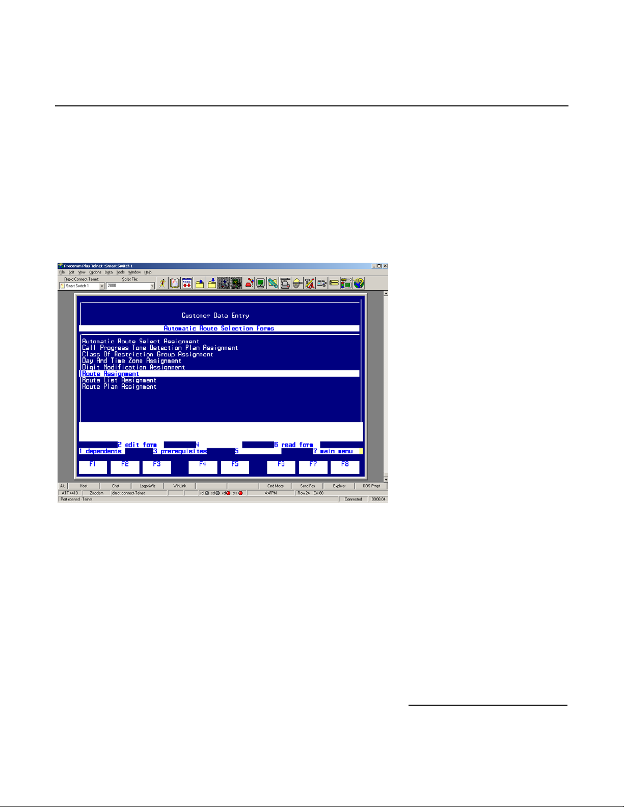
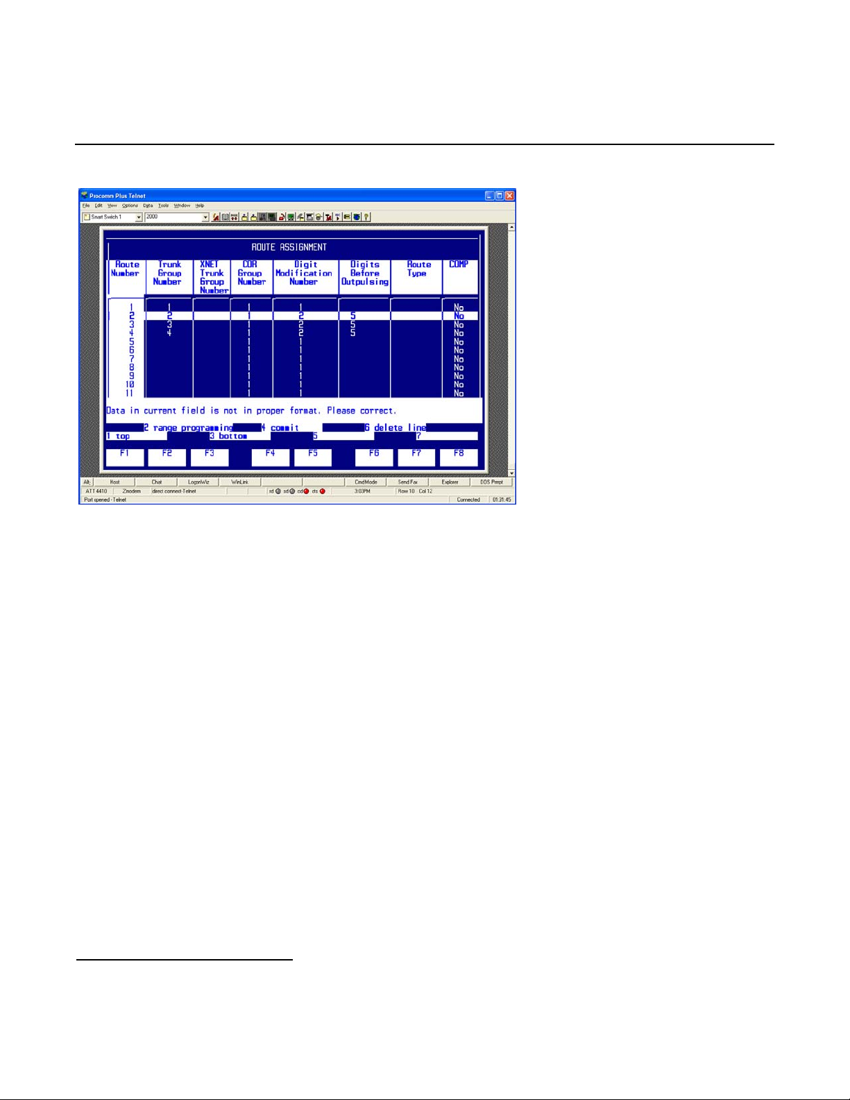
Step 3: In the ARS menu, select Route Assignment and press [ESC] then [2] to edit the Route
Assignment form.
Configure the form as follows:
41
Page 42
Mitel SX-2000 Lightware
Note: Parameters not listed below can be left at their default settings.
• Select an unused Route Number.
• Set Trunk Group Number to the trunk group number defined in Step 11 of the SX-2000 Light
Administration.
• Set COR Group Number to 1.
• Set Digit Modification Number to the digital modification number defined in Step 2 of the Automatic
Route Selection.
• Set Digits Before Outpulsing to 5.
• Press [ESC] then [4] to commit to changes and [ESC] then [1] to confirm the changes.
• Press [ESC] then [Q] to return to the ARS Forms menu.
42
Page 43
Dialogic® 4000 Media Gateway Series Integration Note
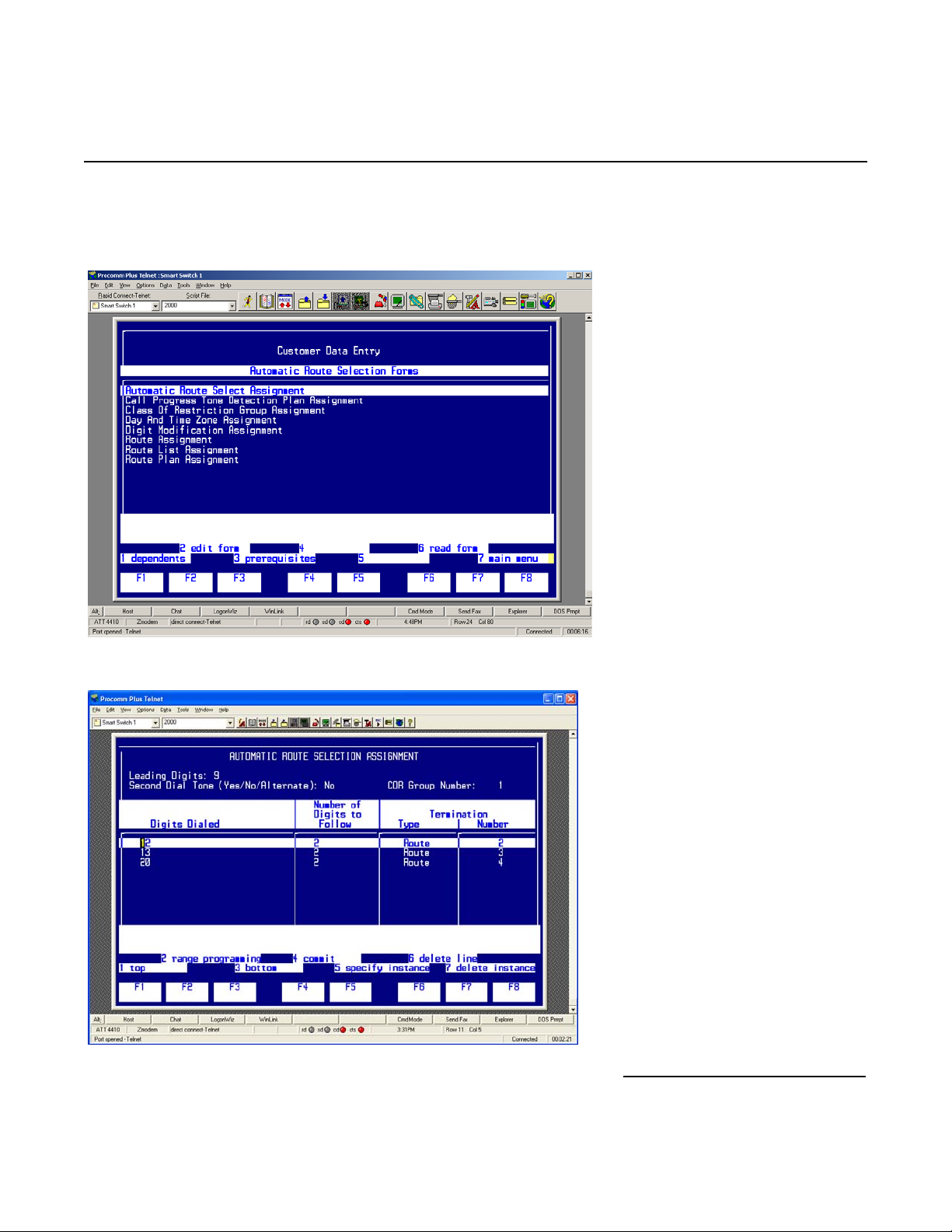
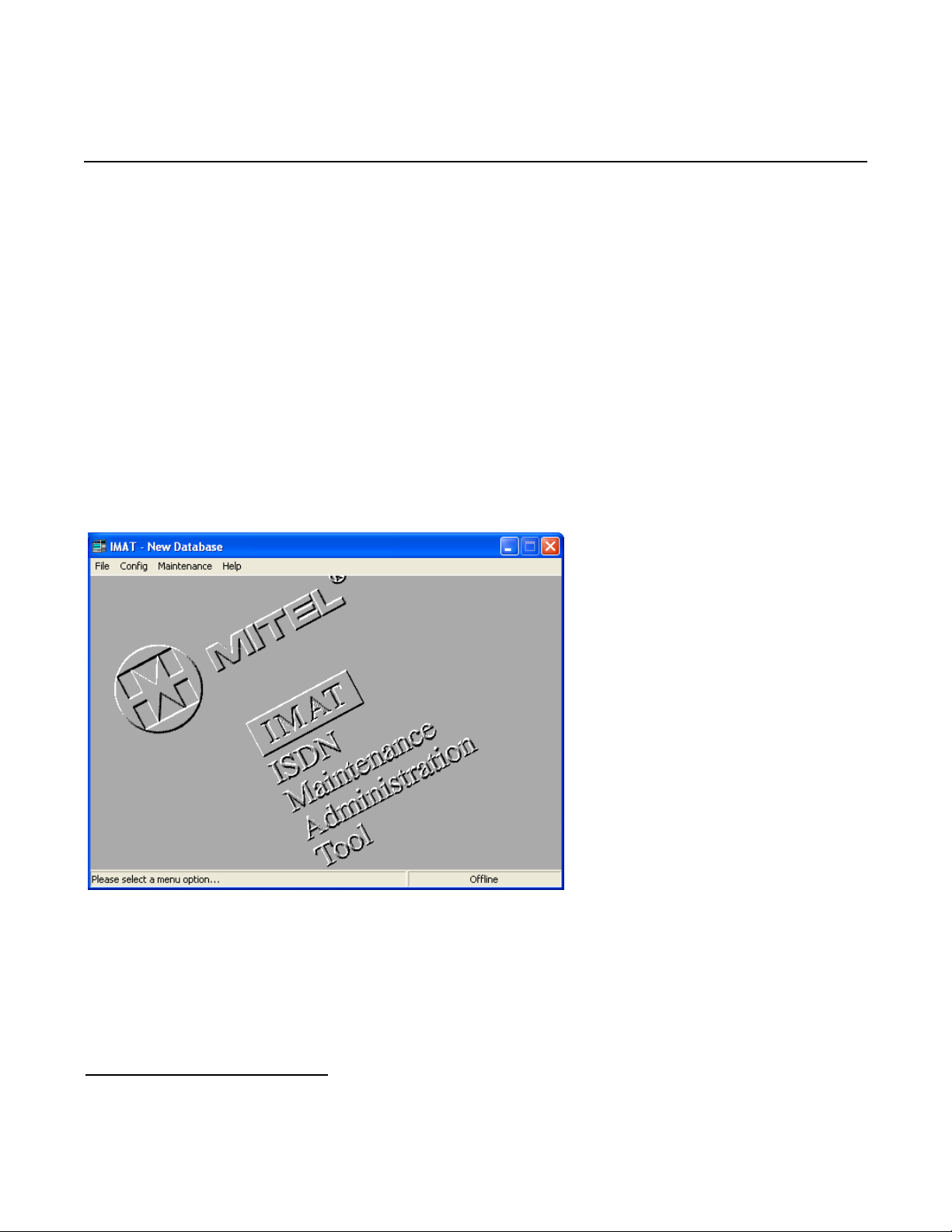
Step 4: In the ARS menu, select Automatic Route Selection Assignment and press [ESC] then [2] to
edit the Automatic Route Selection Assignment form.
Configure the form as follows:
43
Page 44
Mitel SX-2000 Lightware
Note: Parameters not listed below can be left at their default settings.
• Set Leading Digits to a currently unassigned ARS number.
• Set Digits Dialed to an unused 2-digit string.
• Set Number of Digits to Follow to 2.
• Set Termination Type to Route.
• Set Termination Number to 2.
• Press [ESC] then [4] to commit to changes and [ESC] then [1] to confirm the changes.
• Press [ESC] then [Q] to return to the ARS Forms menu.
• Continue to press [ESC] then [Q] until you are logged out of the system.
6.1.1.3 NSU Configuration/IMAT Programming
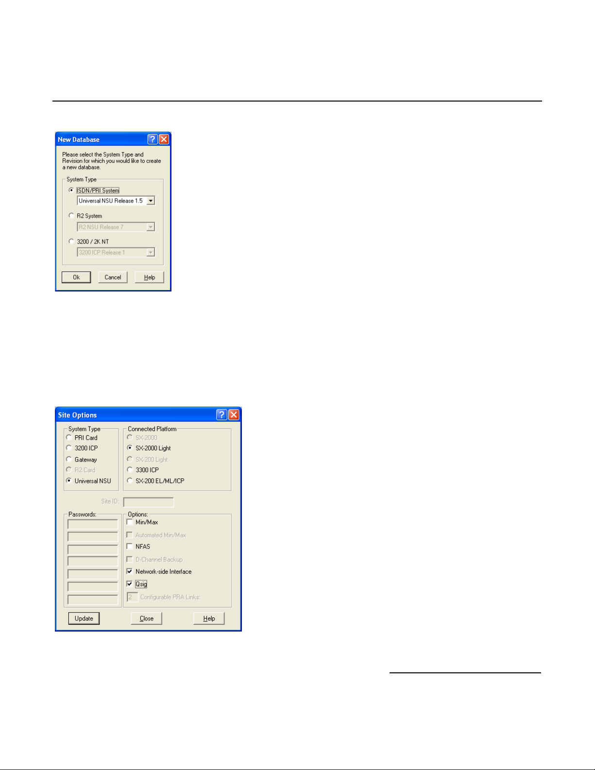
Step 1: Open up IMAT and create a new database as follows:
Select File > New Database.
44
Page 45
Dialogic® 4000 Media Gateway Series Integration Note
• Select the appropriate version of the database based on the version of Mitel SX-2000 Light Software being
used. If you use the SX-2000 Light software version 34.2.0.20, select from the dropdown menu under
ISDN/PRI System the Universal NSU Release 1.5.
• Click OK to create the new database.
Step 2: Configure the Site Options as follows:
Select Config > System Configuration > Site Options.
• Under System Type, select Universal NSU.
• Under Connected Platforms, select SX-2000 Light.
45
Page 46
Mitel SX-2000 Lightware
• Under Options, select Network-side Interface and Qsig.
• Click Update and then Close.
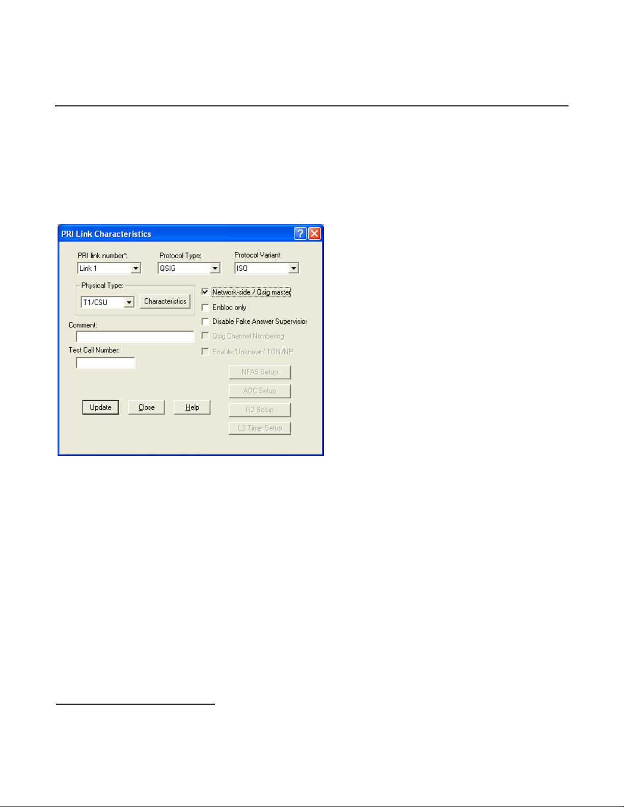
Step 3: Configure the PRI Link Characteristics as follows:
Select Config > System Configuration > PRI Link Characteristics.
Note: Parameters not listed below can be left at their default settings.
• Set PRI link number* to the link number in which the T1 Q.SIG is installed.
• Set Protocol Type to QSIG.
• Set Protocol Variant to ISO.
• Set Physical Type to T1/CSU.
• Select Network-side / Qsig master.
• Click the Characteristics button.
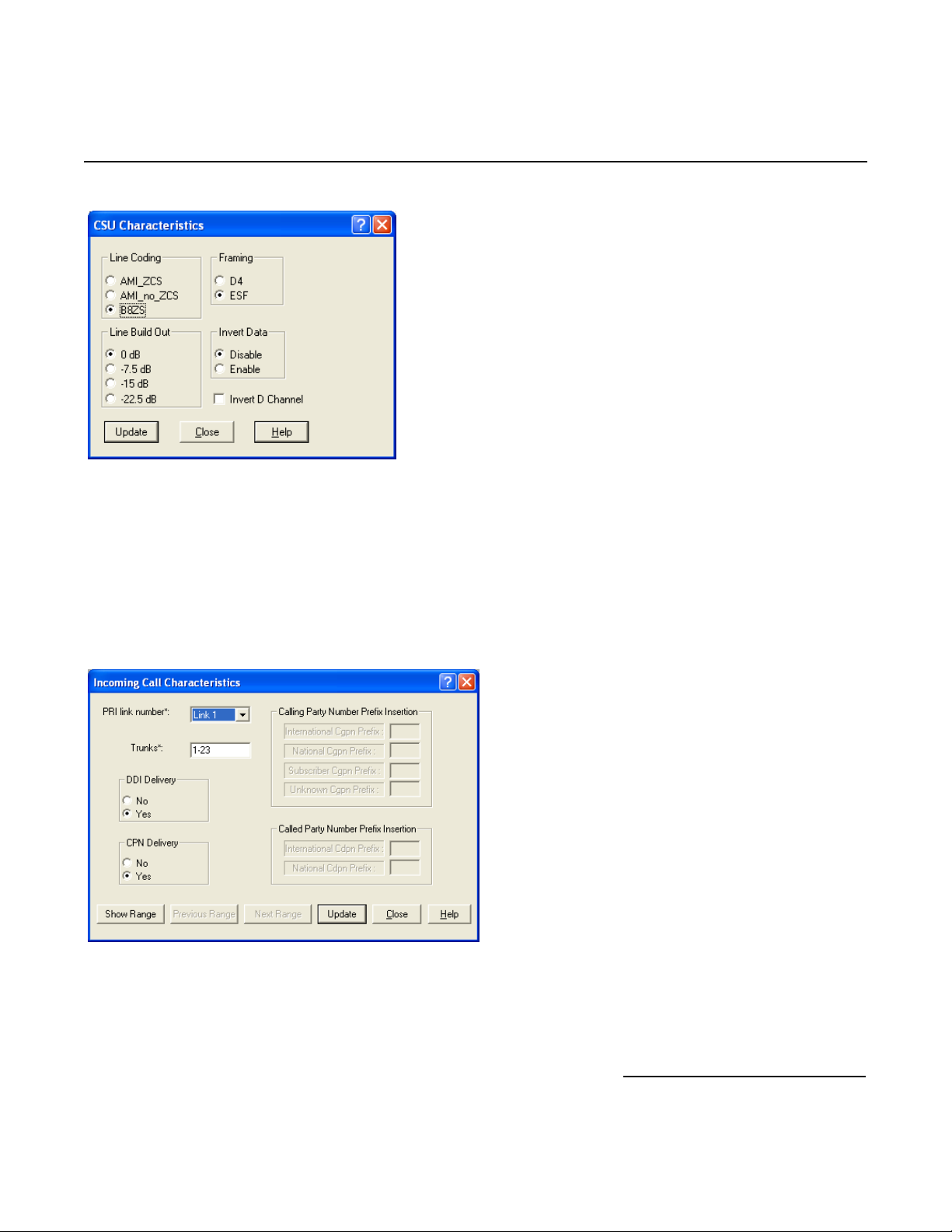
• Configure the T1/CSU Characteristics as follows:
46
Page 47
Dialogic® 4000 Media Gateway Series Integration Note
• Under Line Coding, select B8ZS.
• Under Framing, select ESF.
• Under Line Build Out, select 0 dB.
• Under Invert Data, select Disable.
• Click Update and Close.
Step 4: Configure the Incoming Call Characteristics as follows:
Select Config > Incoming Call Characteristics.
• Set PRI link number* to the link number that the T1 QSIG is installed.
• Set Trunks* to 1-23.
• Set DDI Delivery to Yes.
• Set CPN Delivery to Yes.
• Click Update and Close.
47
Page 48
Mitel SX-2000 Lightware
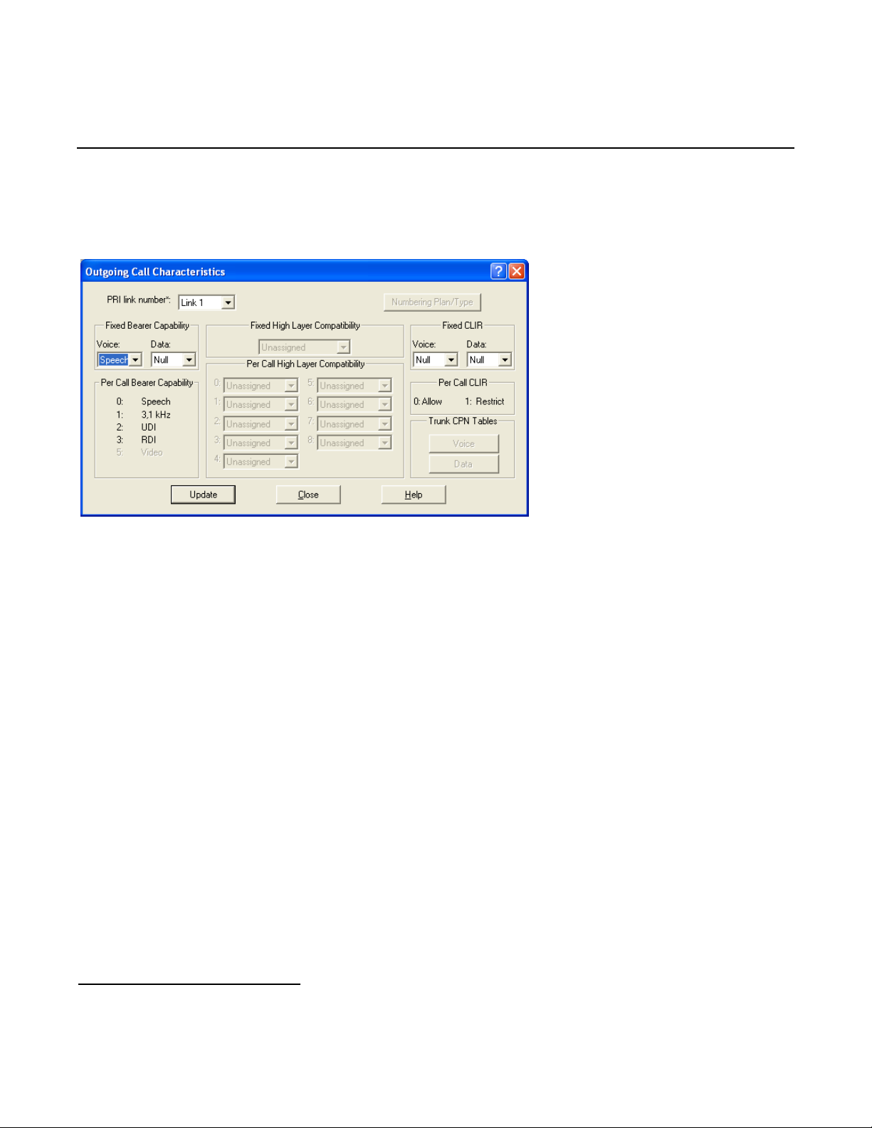
Step 5: Configure the Outgoing Call Characteristics as follows:
Select Config > Outgoing Call Characteristics.
Note: Parameters not listed below can be left at their default settings.
• Set PRI link number* to the link number on which the T1 Q.SIG is installed.
• Under Fixed Bearer Capability, set the parameter Voice to Speech.
• Click Update and Close.
48
Page 49
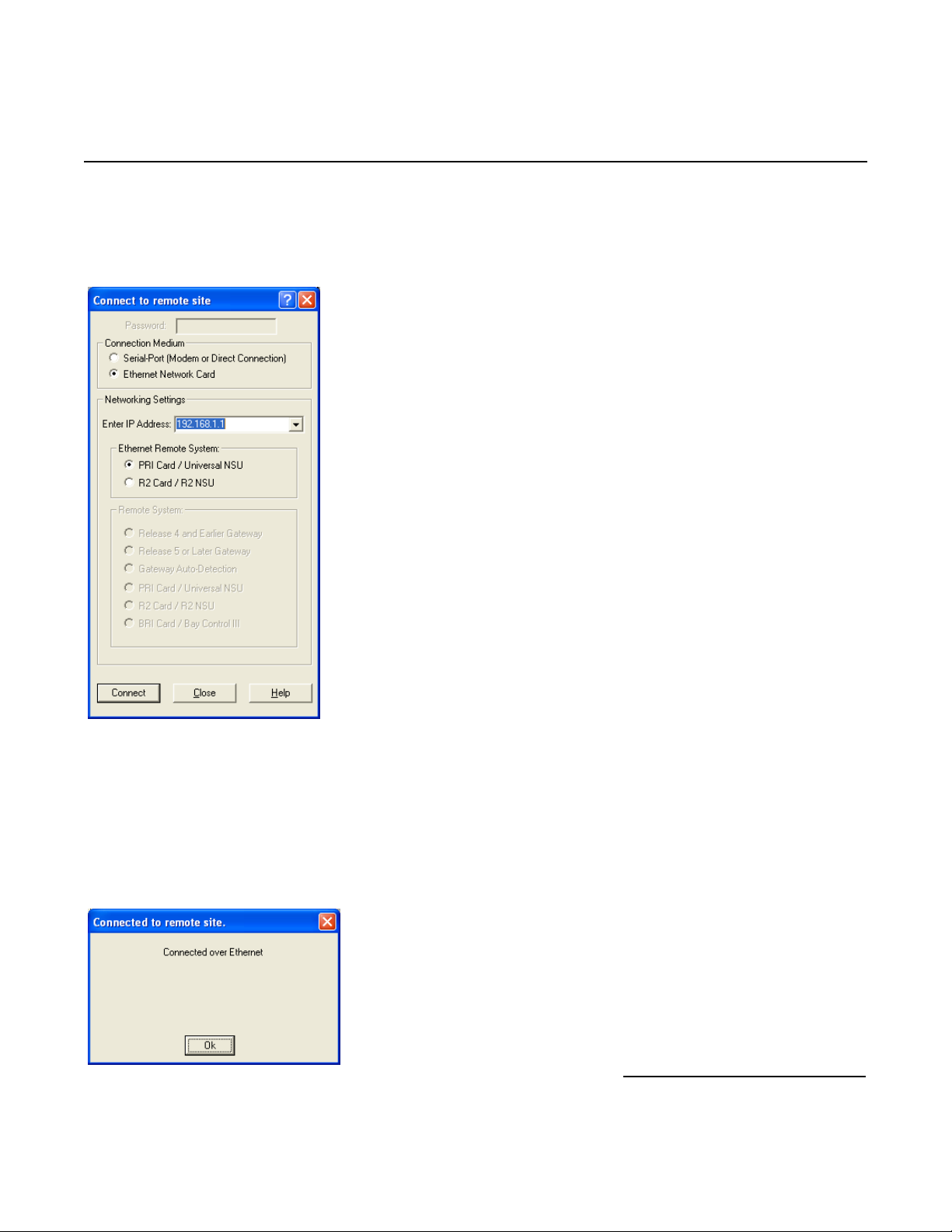
Step 6: Configure the Connection to Remote Sites as follows:
Select File > Connect to Remote Site.
Dialogic® 4000 Media Gateway Series Integration Note
Note: Parameters not listed below can be left at their default settings.
• Set Connection Medium to Ethernet Network Card.
• Under Network Settings, enter the IP address of the 3300 Universal NSU (The default value is
192.168.1.1.).
• Set Ethernet Remote System to PRI Card / Universal NSU.
• Click Connect.
• Click OK at the Connected to remote site dialog box.
49
Page 50
Mitel SX-2000 Lightware
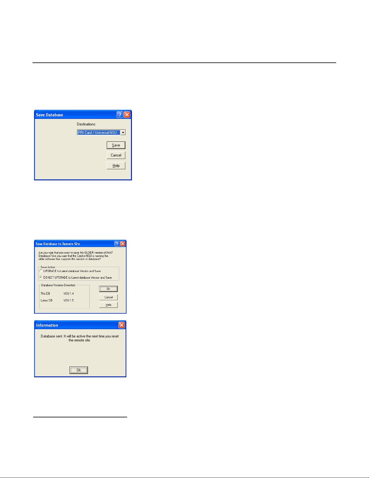
Step 7: Save the database as follows:
Click File > Save > Database.
• Set Destinations to PRI Card / Universal NSU.
• Click Save.
Note: If a dialog box appears stating “Are you sure you want to save this OLDER version of
IMAT Database? select DO NOT UPGRADE to the latest database Version and
Save and click OK.
Click OK at the Information dialog box stating that the database has been sent.
50
Page 51
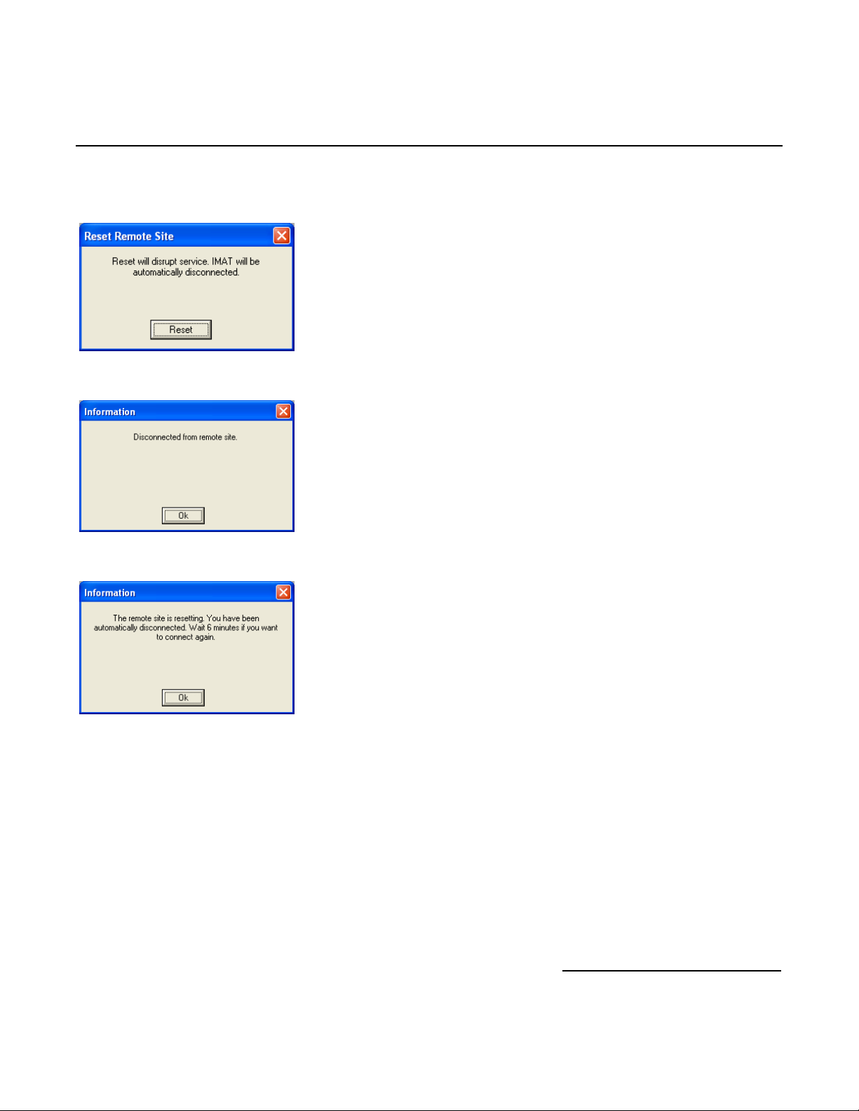
Click Maintenance > Remote Site Reset.
Dialogic® 4000 Media Gateway Series Integration Note
Click the Reset button.
Click OK in the Information dialog box stating that IMAT is “Disconnected from remote site.”
Click OK in the dialog box stating that the remote site is resetting.
51
Page 52

Mitel SX-2000 Lightware
7. Microsoft® Office Communications Server 2007 (OCS) Setup
7.1 Steps for configuring Microsoft® OCS
Normalization rules are used to convert dial numbers into full E.164 formatted numbers. Microsoft
the standard E.164 format to search for users listed in the Active Directory (AD).
If a Microsoft
®
OCS user dials an internal extension number (normally 3-5 digits), the normalization rules convert
it into full E.164 format. These normalization rules should cover dialed digits for internal extensions, local
numbers, long distance numbers, and international numbers.
To configure Microsoft
®
OCS, click
Start > Programs > Administrative Tools > OCS 2007.
On the tree presented in the configuration window, right-click Forest then select Properties and then Voice
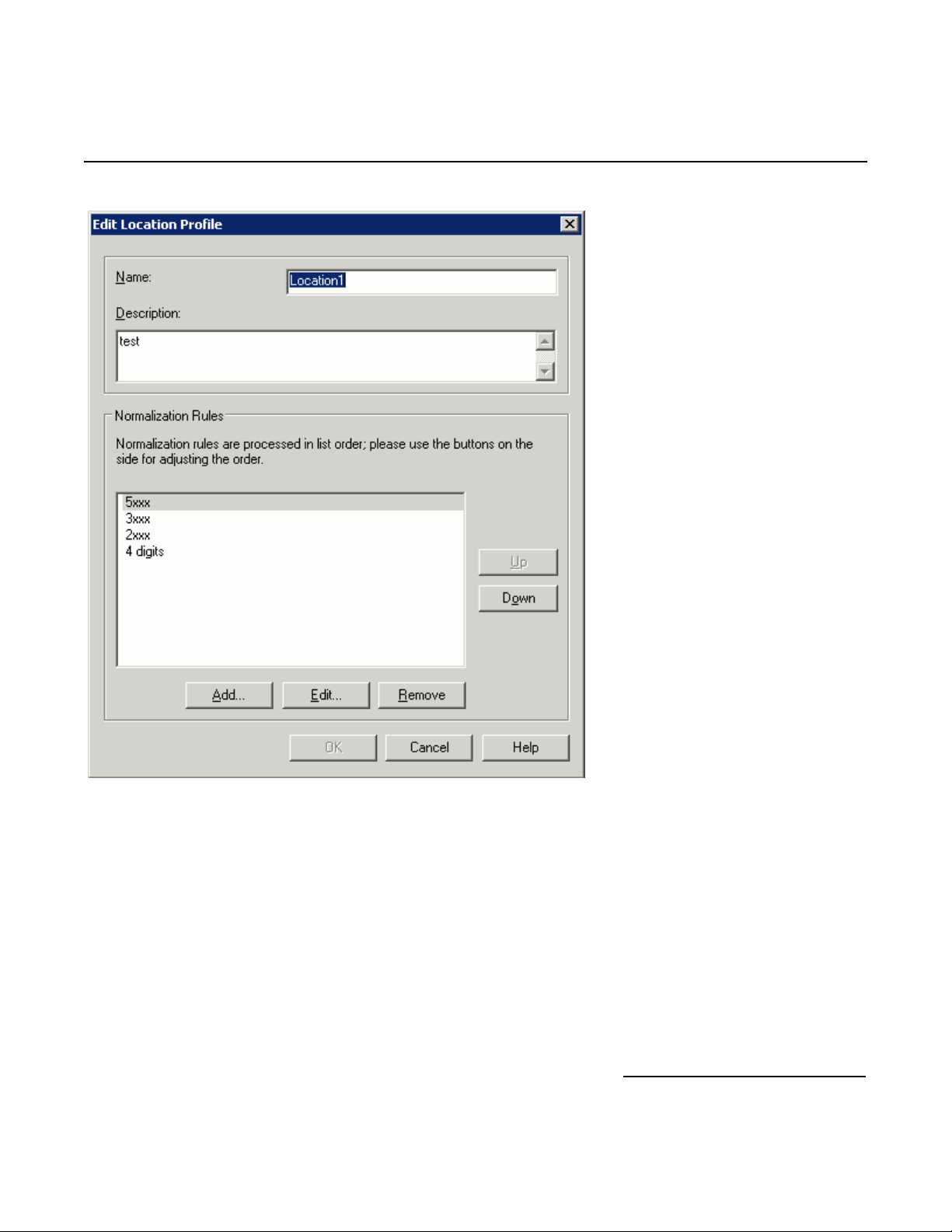
Properties form the menu provided. Edit a location profile as shown in the following example:
®
OCS uses
52
Page 53
Dialogic® 4000 Media Gateway Series Integration Note
Click Add or Edit to create or change a particular rule.
53
Page 54
Mitel SX-2000 Lightware
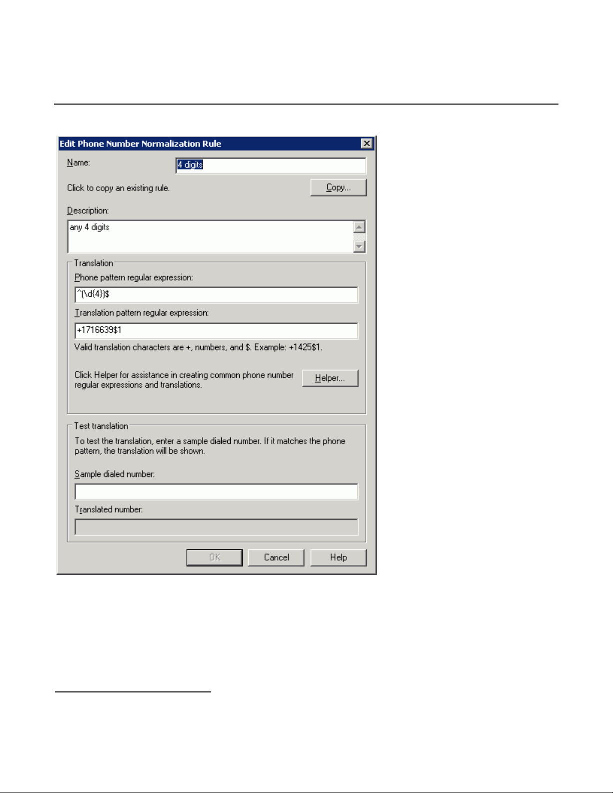
In this example, when a user dials any 4-digit number, it will be converted to its E.164 equivalent of
+1716639xxxx and then that number will be searched for in AD.
54
Page 55

Dialogic® 4000 Media Gateway Series Integration Note
More examples are shown in the following table:
Name Phone Pattern Translation Pattern Comments
Extensions ^(\d{4})$ +1716639$1 Internal extensions
Local ^(\d{7})$ +1716$1 Local number
National ^1(\d*)$ +1$1 Long distance number
International ^011(\d*) +$1 International number
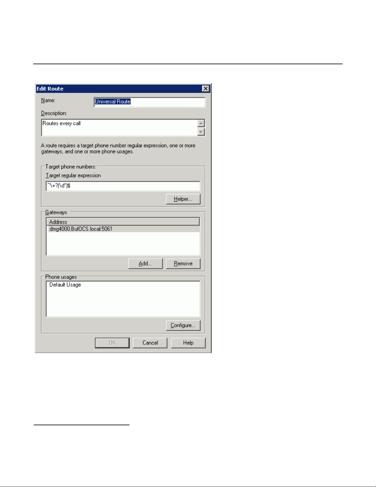
A default route is used to route all calls to Microsoft
different Microsoft
To configure Microsoft
®
Mediation Server, configure the Target phone numbers field accordingly.
®
OCS, click
®
Mediation Server. If you need to route some calls to a
Start > Programs > Administrative Tools > OCS 2007.
On the tree presented in the configuration window, right-click Forest then select Properties and then Voice
Properties form the menu provided. Edit a route as shown in the example below.
55
Page 56
Mitel SX-2000 Lightware
This entry routes numbers with or without “+” prefix followed by any digits to Microsoft
dmg4000.bufocs.local.
Restart the Front End Services for the above changes to take effect, including all normalization rules. This can
be done from the window Services.
Note: Unless the dialed number from Microsoft
format, Microsoft
56
®
OCS must find a normalization rule to convert the dialed number to E.164. If no rule is found
®
OCS client (such as Microsoft® Office Communicator) is in E.164
®
Mediation Server
Page 57
Dialogic® 4000 Media Gateway Series Integration Note
or matched, outbound calls will fail. In this case, Dialogic® Diva® Diagnostics trace will not receive an outbound
SIP message, since the call will not yet have reached the SIP gateway.
7.2 Steps for configuring Microsoft® Office Communications Server 2007 (OCS)
clients
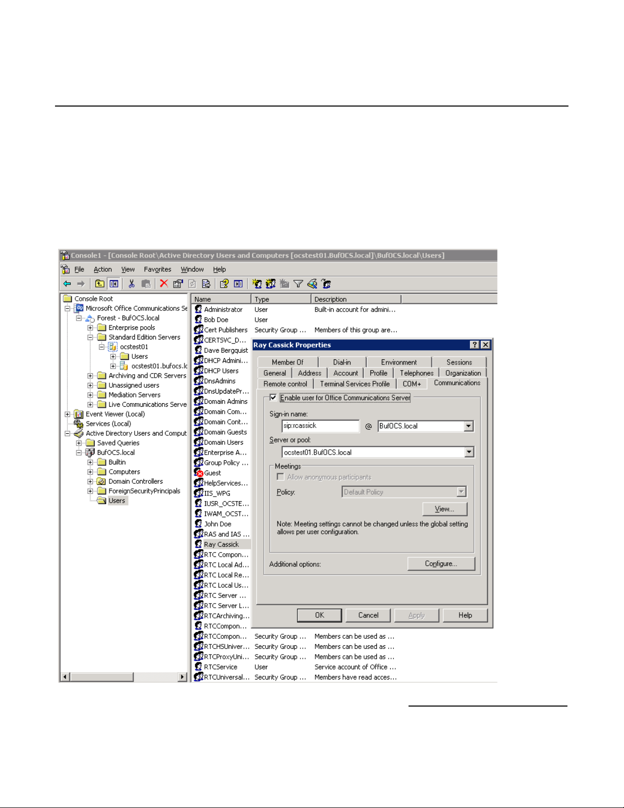
The domain users need to be enabled for making calls through Microsoft
®
OCS.
57
Page 58
Mitel SX-2000 Lightware
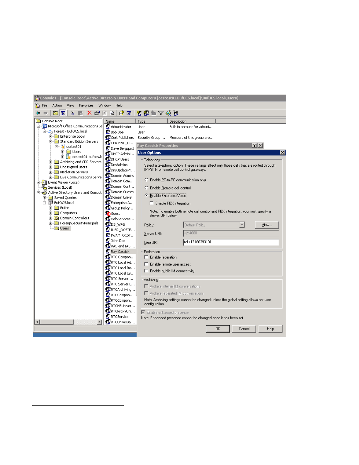
Under the Communications tab, check the Enable user for Office Communications Server option
and then click the Configure button.
In the above configuration for the hypothetical user Ray Cassick, an inbound PSTN call for 3101 will be
converted by the Dialogic
®
Diva® SIPcontrol™ Software to +17166393101 because in the Diva SIPcontrol
software dialpan in the SIP Peer Configuration section under Address Normalization the:
• Number format (outbound) is set to International number, and
• Encoding (outbound) is set to Use type flag.
Microsoft
Communicator or any Microsoft
58
®
OCS will ring the user Ray Cassick if he is logged on to Microsoft® OCS from Microsoft® Office
®
OCS supported device.
Page 59

Dialogic® 4000 Media Gateway Series Integration Note
8. Microsoft® Mediation Server Installation and Configuration
8.1 Installation
The gateways of the Dialogic
Microsoft
running Microsoft
Microsoft
®
Mediation Server software. You can complete the Microsoft® Mediation Server configuration by
®
®
OCS Deployment Wizard, select Deploy Other Server Roles, then select Deploy Mediation
Office Communications Server 2007 (OCS) “Setup.exe” in the DMG4000 Gateways. In the
Sever. Follow the steps in the Wizard to complete the setup:
Step 1: Install the Microsoft
Step 2: Activate Microsoft
account.
Step 3: No action needed. Do this step when the installation is complete.
Step 4: Configure Certificate.
1. Download the CA certification path for Microsoft
• From Start > Run, enter http://<CA server>/certsrv
• Select to download a CA certificate, chain or CRL.
• Click Download CA certificate chain.
• In File Download, click Save.
2. Install the certificate chain for the Microsoft
• In the Deployment Wizard, run step 4 again.
• Select Import a certificate chain from a .p7b file in step 1.
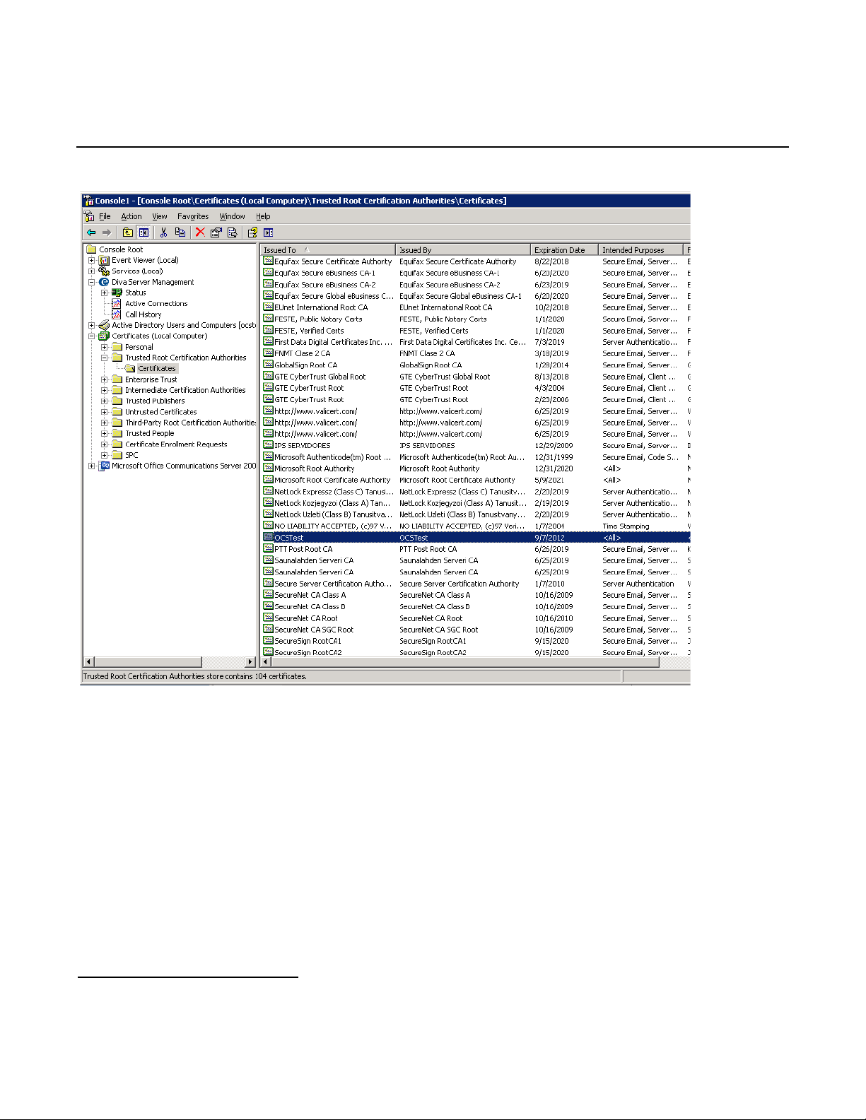
3. Verify that your CA is in the list of Trusted root CAs:
• In the Microsoft
done, add it.)
• Verify that CA is on the list of trusted CAs as shown in the example below.
®
4000 Media Gateway Series (DMG4000 Gateways) are shipped with pre-installed
®
Mediation Server software.
®
Mediation Server. Use the existing account and enter the password for the service
®
Mediation Server.
®
Mediation Server:
®
Management Console (MMC) snap-in, click Certificates (If not already
59
Page 60
Mitel SX-2000 Lightware
4. Create the certificate request for the Microsoft
• Run Deployment Wizard, click step 4.
• Select the option Create a new certificate.
• Select the option Send the request immediately to an online CA.
• Complete the settings in the blank.
• Click Assign to complete the task.
Note: If you receive the error message “certificate expired or is not yet valid” when you click the assign button at
the end of step 4, check the time/time zone configured for your Microsoft
the Deployment Wizard again or click Certificates in Available tasks in Microsoft
MMC snap-in.
60
®
Mediation Server:
®
Mediation Server is correct, then run
®
Mediation Server
Page 61
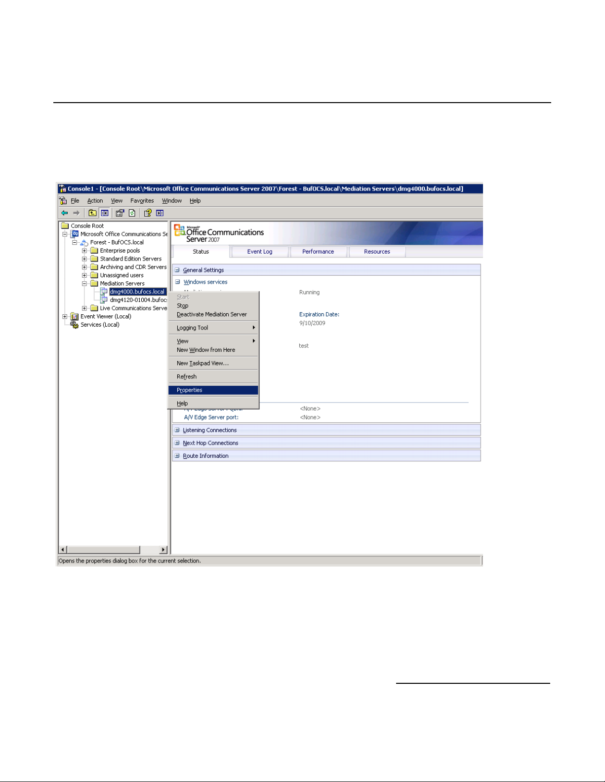
8.2 Configuration
From the MMC snap-in, right-click the detected Microsoft
Dialogic® 4000 Media Gateway Series Integration Note
®
Mediation Server and select Properties.
61
Page 62
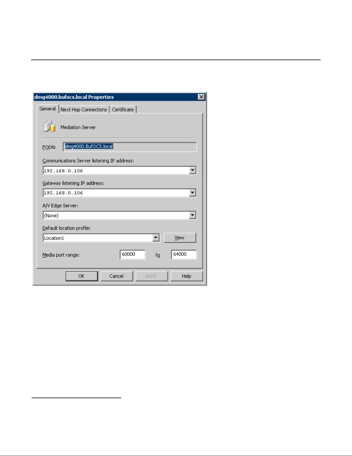
Mitel SX-2000 Lightware
Configure the following settings on the General tab:
62
Page 63
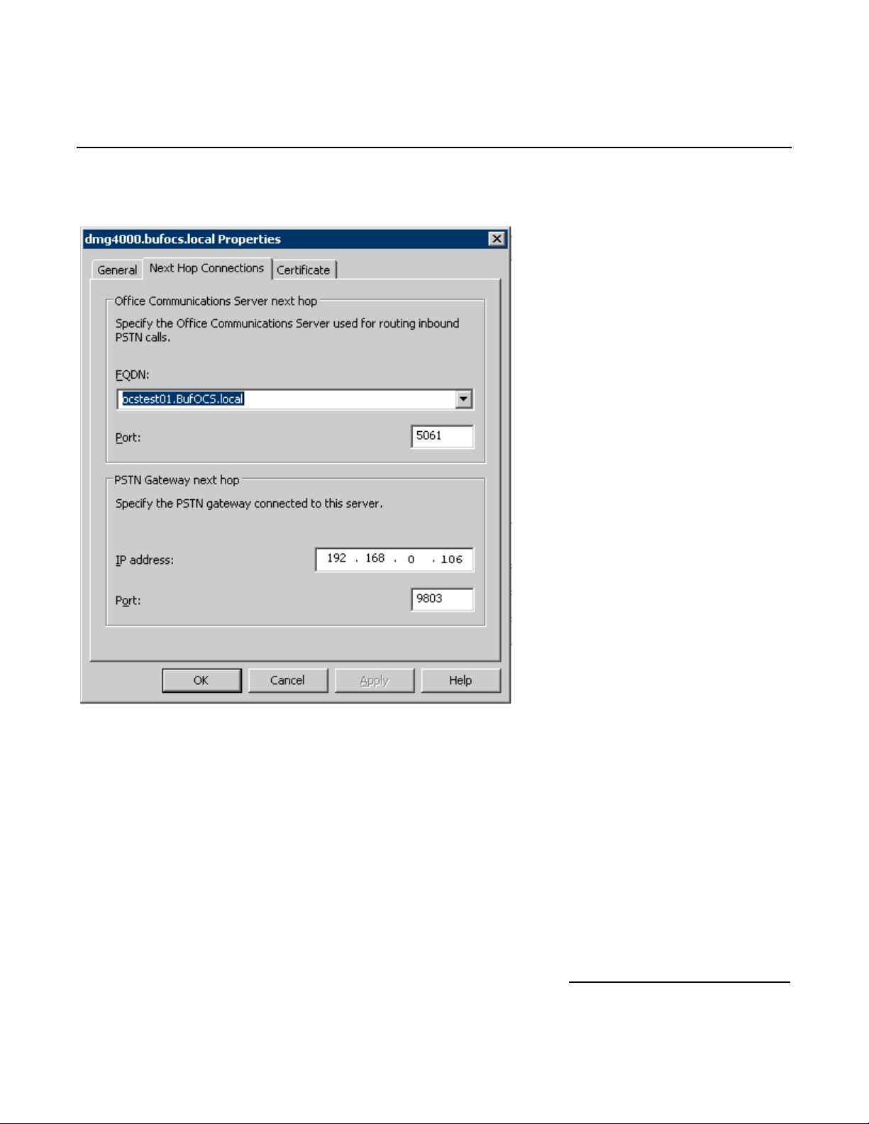
Click the Next Hop Connections tab and configure the following:
Dialogic® 4000 Media Gateway Series Integration Note
The Port entry under PSTN Gateway Next hop has to match the configuration in the Dialogic
SIPcontrol™ Software under Network Interface Configuration > SIP Listen Port.
®
Diva®
63
Page 64
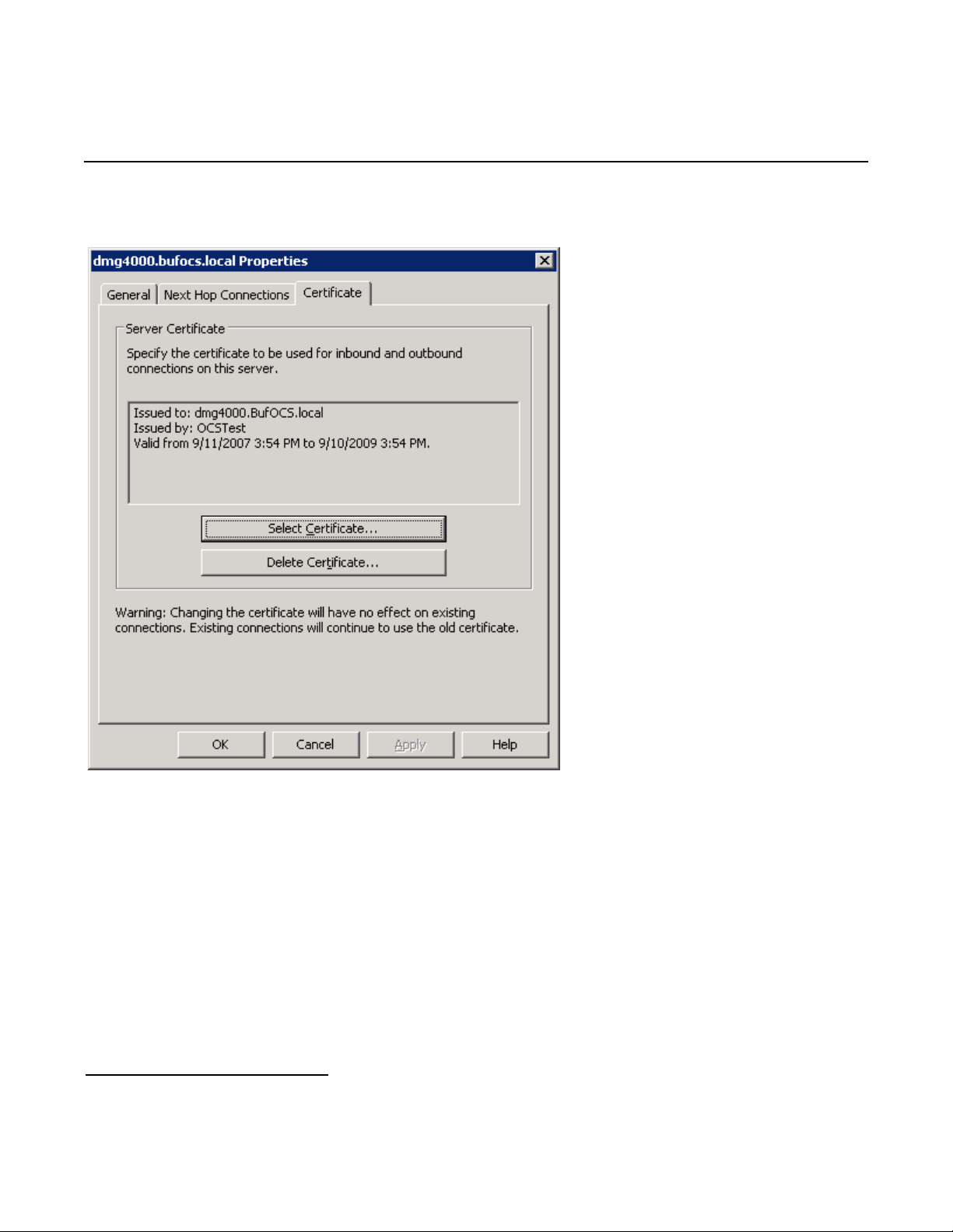
Mitel SX-2000 Lightware
Click the Certificate tab.
Select the certificate that will be used to communicate with Microsoft
need to restart for these changes to properly take effect.
®
OCS. Microsoft® Mediation Server will
9. Testing the Validation Matrix
The table below shows various test scenarios that are run as typical validation scenarios if the Dialogic
Gateway is used in a voice messaging situation. The notes column specifies any notable parts of the test.
The test scenarios below assume that all gateway configuration parameters are at their default values. For a
sample showing call flows and states please consult the Gateway SIP Compatibility Guide.
64
®
Media
Page 65
Test
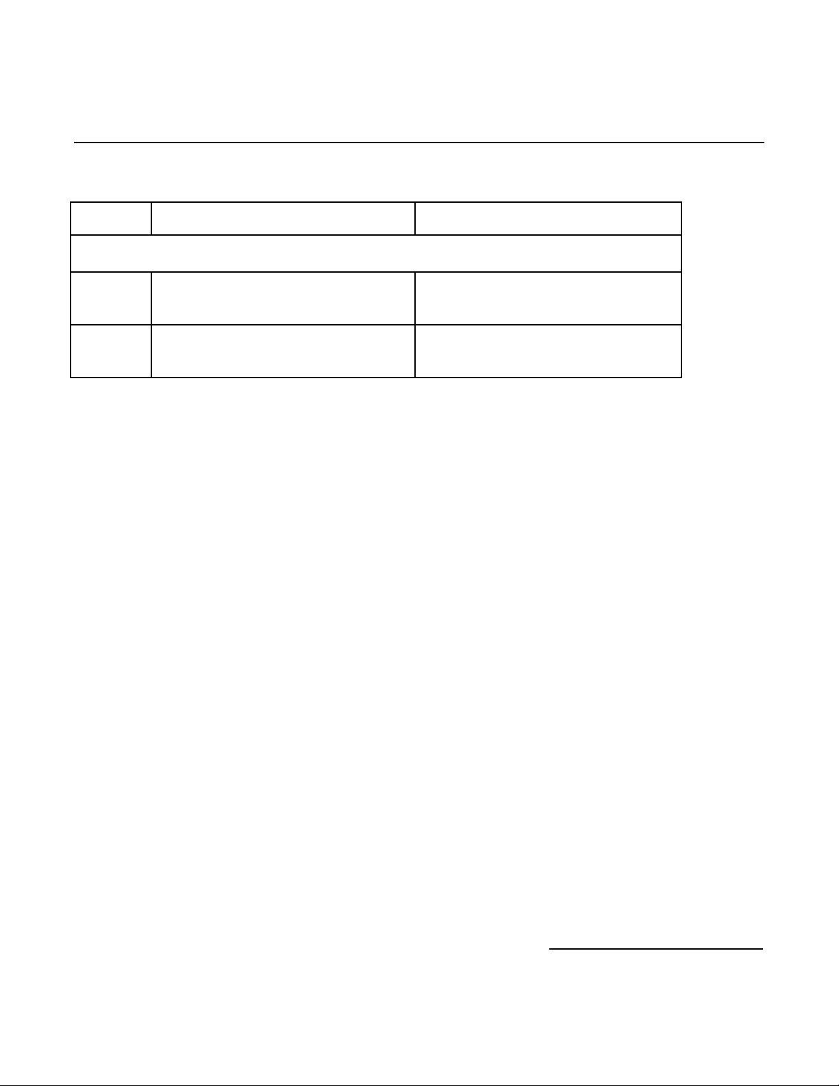
Call Scenario Description Notes
Number
Inbound call scenarios
Dialogic® 4000 Media Gateway Series Integration Note
1 Direct call from TDM station set to
Microsoft
®
OCS client.
2 Direct call from Microsoft® OCS client to
TDM station set.
10. Troubleshooting
10.1 Important Debugging Tools
• Ethereal/Wireshark: Can be used to view and analyze the network captures provided by the Dialogic
gateway diagnostic firmware.
• Adobe Audition: Can be used to review and analyze the audio extracted from the network captures to
troubleshoot any audio related issues.
• Dialogic
calls going into and leaving the Dialogic
®
Diva® Diagnostics tool: Used to review and analyze all SIP and ISDN traffic that relates to
®
4000 Media Gateway.
10.2 Using the Dialogic® Diva® Diagnostics Tool
Before using the Dialogic
SIPcontrol™ Software debug. To do so, open the Diva SIPcontrol software web interface, click the link System
Settings, and set Debug Level to Extended. Click the Save button for the changes to take effect.
Now, you can start the Diva Diagnostics tool. To do so, click:
Start > Programs > Dialogic Diva > Diagnostics.
®
Diva® Diagnostics tool, you would need to enable it by setting the Dialogic® Diva®
65
Page 66
Mitel SX-2000 Lightware
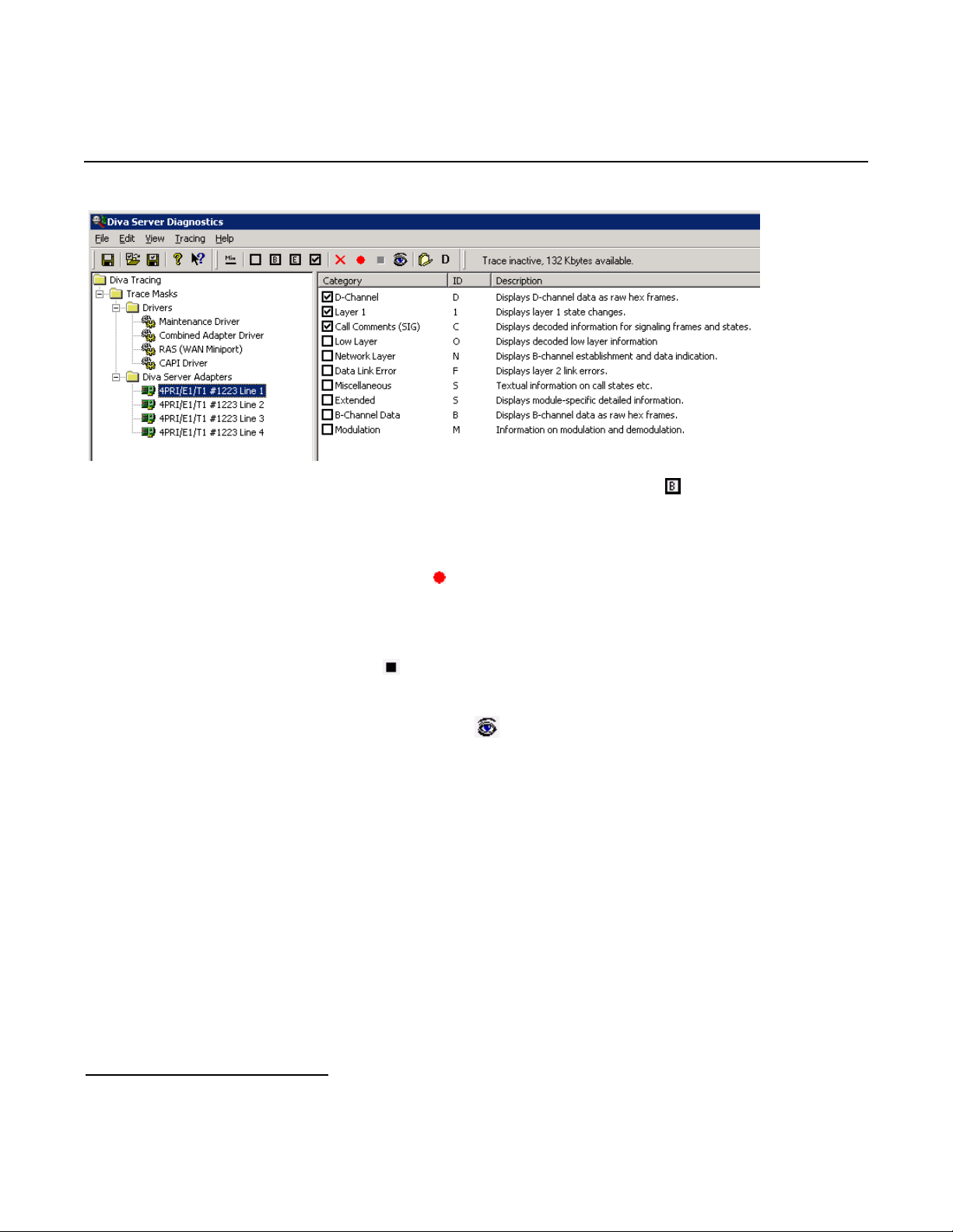
1. Click one line of your Dialogic
®
Diva® Media Board in the left pane and click on the toolbar to activate
the Basic tracing level. This level captures Q.931 ISDN messages.
2. Click CAPI driver in the left pane and activate the Basic tracing level as explained in step 1.
3. Start tracing. To do so, click the start icon
or select the Start Tracing option form the Tracing
menu.
4. Reproduce the issue.
5. To stop tracing, click the stop icon
on the tool bar or select the Stop Tracing option form the
Tracing menu.
6. To view your collected trace, click the view icon
on the toolbar or select the View Recorded
Trace option from the View menu. A notepad window will open with the recorded log.
66
Page 67

Dialogic® 4000 Media Gateway Series Integration Note
Examples of Dialogic® Diva® Diagnostics traces for an inbound (TDM to IP) call to Microsoft® Office
Communications Server 2007 (OCS)
Basic notations for reading the trace:
• SIG-R: RX Q.931 ISDN message
• SIG-X: TX Q.931 ISDN message
• SIPR: RX SIP message
• SIPX: TX SIP message
< Below is a RX Q.931 ISDN message for an inbound call >
…
9:16:28.431 C 3 21:2389:383 - SIG-R(030) 08 02 00 17 05 04 03 80 90 A2 18 03 A9 83 81 6C 06 01 A0 33
30 30 32 70 05 C1 35 31 30 31
Q.931 CR0017 SETUP
Bearer Capability 80 90 a2
Channel Id a9 83 81
Calling Party Number 01 a0 '2401'
Called Party Number c1 '5101'
…
<Below is a TX SIP message with SDP>
9:16:28.431 1 L 12 00010000-SIPX begin to IP:192.168.0.106 port:5060 socket:3 Proto:TCP
9:16:28.431 1 L 12 00010000- >INVITE sip:[email protected]:5060 SIP/2.0
9:16:28.431 1 L 12 00010000- >Via: SIP/2.0/TCP 192.168.0.106:9803;branch=z9hG4bK2617534104-7603272
9:16:28.431 1 L 12 00010000- >Max-Forwards: 70
9:16:28.431 1 L 12 00010000- >Allow: INVITE,ACK,CANCEL,BYE,OPTIONS,NOTIFY,REFER
9:16:28.431 1 L 12 00010000- >Accept: application/sdp,application/simple-message-summary
9:16:28.431 1 L 12 00010000- >Supported: timer,replaces
9:16:28.431 1 L 12 00010000- >From: "Dialogic Diva SIPcontrol"
<sip:[email protected];user=phone>;tag=sipcontrol_2617534104-7668808
9:16:28.431 1 L 12 00010000- >To: "Default" <sip:[email protected];user=phone>
9:16:28.431 1 L 12 00010000- >Call-ID: 9c046698-730448-17@dmg4000
9:16:28.431 1 L 12 00010000- >CSeq: 1 INVITE
9:16:28.431 1 L 12 00010000- >Min-SE: 90
9:16:28.431 1 L 12 00010000- >Session-Expires: 600;refresher=uac
9:16:28.431 1 L 12 00010000- >Contact: <sip:[email protected]:9803>
9:16:28.431 1 L 12 00010000- >Content-Type: application/sdp
9:16:28.431 1 L 12 00010000- >Content-Length: 253
9:16:28.431 1 L 12 00010000- >
9:16:28.431 1 L 12 00010000- >v=0
9:16:28.431 1 L 12 00010000- >o=SIPcontrol 7472200 7472200 IN IP4 192.168.0.106
9:16:28.431 1 L 12 00010000- >s= 9:16:28.431 1 L 12 00010000- >c=IN IP4 192.168.0.106
9:16:28.431 1 L 12 00010000- >t=0 0
9:16:28.431 1 L 12 00010000- >m=audio 30060 RTP/AVP 8 0 101 13
9:16:28.431 1 L 12 00010000- >a=rtpmap:8 PCMA/8000
9:16:28.431 1 L 12 00010000- >a=rtpmap:0 PCMU/8000
9:16:28.431 1 L 12 00010000- >a=rtpmap:101 telephone-event/8000
9:16:28.431 1 L 12 00010000- >a=fmtp:101 0-15
9:16:28.431 1 L 12 00010000- >a=rtpmap:13 CN/8000
9:16:28.431 1 L 12 00010000- >a=sendrecv
9:16:28.431 1 L 12 00010000-SIPX end
…
67
Page 68

Mitel SX-2000 Lightware
<Below is a RX SIP message>
9:16:28.431 1 L 12 00010000-SIPR begin (331 byte) from IP:192.168.0.106 PORT:5060 on socket 3 port 5060
TCP
9:16:28.431 1 L 12 00010000- >SIP/2.0 100 Trying
9:16:28.431 1 L 12 00010000- >FROM: "Dialogic Diva
SIPcontrol"<sip:[email protected];user=phone>;tag=sipcontrol_2617534104-7668808
9:16:28.431 1 L 12 00010000- >TO: "Default"<sip:[email protected];user=phone>
9:16:28.431 1 L 12 00010000- >CSEQ: 1 INVITE
9:16:28.431 1 L 12 00010000- >CALL-ID: 9c046698-730448-17@dmg4000
9:16:28.431 1 L 12 00010000- >VIA: SIP/2.0/TCP 192.168.0.106:9803;branch=z9hG4bK2617534104-7603272
9:16:28.431 1 L 12 00010000- >CONTENT-LENGTH: 0
9:16:28.431 1 L 12 00010000- >
9:16:28.431 1 L 12 00010000-SIPR end
…
9:16:28.665 0 L 12 00010000-SIPR begin (408 byte) from IP:192.168.0.106 PORT:5060 on socket 3 port 5060
TCP
9:16:28.665 0 L 12 00010000- >SIP/2.0 183 Session Progress
9:16:28.665 0 L 12 00010000- >FROM: "Dialogic Diva
SIPcontrol"<sip:[email protected];user=phone>;tag=sipcontrol_2617534104-7668808
9:16:28.665 0 L 12 00010000- >TO:
Default<sip:[email protected];user=phone>;epid=CE4C602FA5;tag=3f5ea65423
9:16:28.665 0 L 12 00010000- >CSEQ: 1 INVITE
9:16:28.665 0 L 12 00010000- >CALL-ID: 9c046698-730448-17@dmg4000
9:16:28.665 0 L 12 00010000- >VIA: SIP/2.0/TCP 192.168.0.106:9803;branch=z9hG4bK2617534104-7603272
9:16:28.665 0 L 12 00010000- >CONTENT-LENGTH: 0
9:16:28.665 0 L 12 00010000- >SERVER: RTCC/3.0.0.0 MediationServer
9:16:28.665 0 L 12 00010000- >
9:16:28.665 0 L 12 00010000-SIPR end
…
9:16:28.869 1 L 12 00010000-SIPR begin (399 byte) from IP:192.168.0.106 PORT:5060 on socket 3 port 5060
TCP
9:16:28.869 1 L 12 00010000- >SIP/2.0 180 Ringing
9:16:28.869 1 L 12 00010000- >FROM: "Dialogic Diva
SIPcontrol"<sip:[email protected];user=phone>;tag=sipcontrol_2617534104-7668808
9:16:28.869 1 L 12 00010000- >TO:
Default<sip:[email protected];user=phone>;epid=CE4C602FA5;tag=3f5ea65423
9:16:28.869 1 L 12 00010000- >CSEQ: 1 INVITE
9:16:28.869 1 L 12 00010000- >CALL-ID: 9c046698-730448-17@dmg4000
9:16:28.869 1 L 12 00010000- >VIA: SIP/2.0/TCP 192.168.0.106:9803;branch=z9hG4bK2617534104-7603272
9:16:28.869 1 L 12 00010000- >CONTENT-LENGTH: 0
9:16:28.869 1 L 12 00010000- >SERVER: RTCC/3.0.0.0 MediationServer
9:16:28.869 1 L 12 00010000- >
9:16:28.869 1 L 12 00010000-SIPR end
…
9:16:30.197 1 L 12 00010000-SIPR begin (836 byte) from IP:192.168.0.106 PORT:5060 on socket 3 port 5060
TCP
9:16:30.197 1 L 12 00010000- >SIP/2.0 200 OK
9:16:30.197 1 L 12 00010000- >FROM: "Dialogic Diva
SIPcontrol"<sip:[email protected];user=phone>;tag=sipcontrol_2617534104-7668808
9:16:30.197 1 L 12 00010000- >TO:
Default<sip:[email protected];user=phone>;epid=CE4C602FA5;tag=3f5ea65423
9:16:30.197 1 L 12 00010000- >CSEQ: 1 INVITE
9:16:30.197 1 L 12 00010000- >CALL-ID: 9c046698-730448-17@dmg4000
9:16:30.197 1 L 12 00010000- >VIA: SIP/2.0/TCP 192.168.0.106:9803;branch=z9hG4bK2617534104-7603272
9:16:30.197 1 L 12 00010000- >CONTACT:
<sip:dmg4000.BufOCS.local:5060;transport=Tcp;maddr=192.168.0.106>
9:16:30.197 1 L 12 00010000- >CONTENT-LENGTH: 253
9:16:30.197 1 L 12 00010000- >SUPPORTED: 100rel
9:16:30.197 1 L 12 00010000- >CONTENT-TYPE: application/sdp; charset=utf-8
68
Page 69

Dialogic® 4000 Media Gateway Series Integration Note
9:16:30.197 1 L 12 00010000- >ALLOW: UPDATE
9:16:30.197 1 L 12 00010000- >SERVER: RTCC/3.0.0.0 MediationServer
9:16:30.197 1 L 12 00010000- >ALLOW: Ack, Cancel, Bye,Invite
9:16:30.197 1 L 12 00010000- >
9:16:30.197 1 L 12 00010000- >v=0
9:16:30.197 1 L 12 00010000- >o=- 0 0 IN IP4 192.168.0.106
9:16:30.197 1 L 12 00010000- >s=session
9:16:30.197 1 L 12 00010000- >c=IN IP4 192.168.0.106
9:16:30.197 1 L 12 00010000- >b=CT:1000
9:16:30.197 1 L 12 00010000- >t=0 0
9:16:30.197 1 L 12 00010000- >m=audio 62438 RTP/AVP 8 101
9:16:30.197 1 L 12 00010000- >c=IN IP4 192.168.0.106
9:16:30.197 1 L 12 00010000- >a=rtcp:62439
9:16:30.197 1 L 12 00010000- >a=label:Audio
9:16:30.197 1 L 12 00010000- >a=rtpmap:8 PCMA/8000
9:16:30.197 1 L 12 00010000- >a=rtpmap:101 telephone-event/8000
9:16:30.197 1 L 12 00010000- >a=fmtp:101 0-16
9:16:30.197 1 L 12 00010000- >a=ptime:20
9:16:30.197 1 L 12 00010000-SIPR end
…
<Bellow is a TX Q.931 ISDN message, after SIP session is established>
9:16:30.212 C 3 21:2391:136 - SIG-X(005) 08 02 80 17 07
Q.931 CR8017 CONN
69
Page 70

Mitel SX-2000 Lightware
70
 Loading...