

Page 1

Dialogic® SS7G21 and SS7G22
Signaling Servers
Hardware Manual
www.dialogic.com
Page 2

Copyright© 2004-2008 Dialogic Corporation. All Rights Reserved. You may not reproduce this document in
whole or in part without permission in writing from Dialogic Corporation at the address provided below.
All contents of this document are furnished for informational use only and are subject to change without notice and do not represent a commitment on the part
of Dialogic Corporation or its subsidiaries (“Dialogic”). Reasonable effort is made to ensure the accuracy of the information contained in the document.
However, Dialogic does not warrant the accuracy of this information and cannot accept responsibility for errors, inaccuracies or omissions that may be
contained in this document.
INFORMATION IN THIS DOCUMENT IS PROVIDED IN CONNECTION WITH DIALOGIC® PRODUCTS. NO LICENSE, EXPRESS OR IMPLIED,
BY ESTOPPEL OR OTHERWISE, TO ANY INTELLECTUAL PROPERTY RIGHTS IS GRANTED BY THIS DOCUMENT. EXCEPT AS PROVIDED
IN A SIGNED AGREEMENT BETWEEN YOU AND DIALOGIC, DIALOGIC ASSUMES NO LIABILITY WHATSOEVER, AND DIALOGIC
DISCLAIMS ANY EXPRESS OR IMPLIED WARRANTY, RELATING TO SALE AND/OR USE OF DIALOGIC PRODUCTS INCLUDING LIABILITY
OR WARRANTIES RELATING TO FITNESS FOR A PARTICULAR PURPOSE, MERCHANTABILITY, OR INFRINGEMENT OF ANY
INTELLECTUAL PROPERTY RIGHT OF A THIRD PARTY.
Dialogic products are not intended for use in medical, life saving, life sustaining, critical control or safety systems, or in nuclear facility applications.
It is possible that the use or implementation of any one of the concepts, applications, or ideas described in this document, in marketing collateral produced by
or on web pages maintained by Dialogic may infringe one or more patents or other intellectual property rights owned by third parties. Dialogic does not
provide any intellectual property licenses with the sale of Dialogic products other than a license to use such product in accordance with intellectual property
owned or validly licensed by Dialogic and no such licenses are provided except pursuant to a signed agreement with Dialogic. More detailed information
about such intellectual property is available from Dialogic's legal department at 9800 Cavendish Blvd., 5th Floor, Montreal, Quebec, Canada H4M 2V9.
Dialogic encourages all users of its products to procure all necessary intellectual property licenses required to implement any concepts or
applications and does not condone or encourage any intellectual property infringement and disclaims any responsibility related thereto. These
intellectual property licenses may differ from country to country and it is the responsibility of those who develop the concepts or applications to be
aware of and comply with different national license requirements.
Dialogic, Dialogic Pro, Brooktrout, Cantata, SnowShore, Eicon, Eicon Networks, Eiconcard, Diva, SIPcontrol, Diva ISDN, TruFax, Realblocs, Realcomm
100, NetAccess, Instant ISDN, TRXStream, Exnet, Exnet Connect, EXS, ExchangePlus VSE, Switchkit, N20, Powering The Service-Ready Network,
Vantage, Connecting People to Information, Connecting to Growth and Shiva, among others as well as related logos, are either registered trademarks or
trademarks of Dialogic. Dialogic's trademarks may be used publicly only with permission from Dialogic. Such permission may only be granted by Dialogic's
legal department at 9800 Cavendish Blvd., 5th Floor, Montreal, Quebec, Canada H4M 2V9. Any authorized use of Dialogic's trademarks will be subject to full
respect of the trademark guidelines published by Dialogic from time to time and any use of Dialogic's trademarks requires proper acknowledgement.
The names of actual companies and products mentioned herein are the trademarks of their respective owners.
Publication Date: January 2008
Document Number: 05-2300-007, Issue 7
2
Page 3

Dialogic® SS7G21 and SS7G22 Signaling Servers Hardware Manual
Contents
Part 1: User’s Guide.......................................................................................................... 6
1 Warnings and Cautions ............................................................................................. 7
2Introduction............................................................................................................11
2.1 Purpose............................................................................................................11
2.2 Products...........................................................................................................11
2.3 Power Supplies..................................................................................................12
2.4 Server Board.....................................................................................................12
2.5 Hard Disk Drive.................................................................................................12
2.6 CD-ROM Drive...................................................................................................12
2.7 SS7 Signaling Boards.........................................................................................12
2.8 Ethernet Ports...................................................................................................13
2.9 Cooling.............................................................................................................13
2.10 Related Information...........................................................................................13
2.11 Applicability ......................................................................................................14
3 Product Specification ...............................................................................................15
3.1 DC Power Supply Module...................................... ............................... ...............15
3.2 AC Power Supply Module ....................... .. ................................ ...........................15
3.3 Signaling Links..................................................................................................15
3.4 PCM Interface .............................. .. .. ............................... ................................ ..16
3.5 SS7 Serial Interfaces..........................................................................................16
3.6 Ethernet Interfaces............................................................................................16
3.7 Serial Port (COM2).............................................................................................17
3.8 Alarm Outputs.......................................... ................................ .........................17
3.9 Controls and Indicators ......................................................................................17
3.10 Physical Specifications........................................................................................19
3.11 Environmental Specifications...............................................................................19
3.12 Product Reliability..............................................................................................19
4 Regulatory Specifications and Declarations..............................................................21
4.1 Specifications Demonstrating Compliance..............................................................21
4.1.1 Safety Compliance..................................................................................21
4.1.2 Electromagnetic Compatibility (EMC).........................................................21
4.1.3 Telecommunications Compliance...............................................................22
4.2 Declarations of the Manufacturer or Importer ........................................................23
4.2.1 CE Declaration of Conformity – European Economic Area..............................25
4.2.2 FCC Part 15 ElectroMagnetic Compliance Statement - USA ...........................26
4.2.3 FCC Part 68 Statement - USA...................................................................26
4.2.4 Telecommunications Attachment Notice - Canada........................................27
4.2.5 ICES-003 Electromagnetic Compatibility Notice - Canada .............................27
4.2.6 Telecommunications Notice - Australia / New Zealand .................................27
4.2.7 Telecommunications Notice - Taiwan..........................................................27
4.3 Essential Compliance Information ........................................................................28
4.3.1 Safety...................................................................................................28
4.3.2 EMC......................................................................................................28
4.3.3 Telecommunications................................................................................28
4.3.4 Product Environmental Information...........................................................29
5 Hardware Description ..............................................................................................31
5.1 Overview..........................................................................................................31
5.2 Front Panel.......................................................................................................32
5.3 Back Panel........................................................................................................33
5.4 Rack Mounting Options.......................................................................................34
6Interfaces................................................................................................................35
6.1 DC Power Input Terminal Block....................... .. ................................ .. .................35
6.2 Safety Ground Studs for Earthing.........................................................................35
6.3 AC Power Input ............................................ .. ...................................................35
6.4 PCM Interface Ports ................................ .. ................................ .........................35
6.5 SS7 Serial Interface Ports............................................... ................................ ....36
6.6 Ethernet Interfaces............................................................................................38
6.7 Serial Port (COM2).............................................................................................39
6.8 Alarms .............................................................................................................40
Part 2: Service Technician’s Guide ...................................................................................41
4.3.2.1 Installation of Cables.................................................................28
4.3.2.2 Further Information...................................................................28
3
Page 4

Contents
7 Warnings and Cautions ............................................................................................43
8 Tools and Supplies Needed ......................................................................................47
9 Product Installation and Hot-Swap Actions..............................................................49
9.1 Installation Overview..........................................................................................49
9.2 Power Supply Related Actions..............................................................................50
9.2.1 Safety Ground Studs, Conductor Installation ..............................................51
9.2.2 DC Power Supply Module, Initial Connections..............................................51
9.2.3 DC Power Supply Module, Transferring Connections.....................................53
9.2.4 AC-input Power Supply Cage, Connection...................................................53
9.2.5 Replacing a DC Power Supply Module ........................................................53
9.2.6 Replacing an AC Power Supply Module.......................................................54
9.3 Hard Disk Drive (HDD) Replacement.....................................................................55
9.3.1 Backing up the System Configuration .......................................................56
9.3.2 Replacing the Hardware...........................................................................56
9.3.3 Restoring the System Configuration...........................................................57
10 Working Inside the Product .....................................................................................59
10.1 Safety: Before Removing the Top Cover......................... ............................... .. ... ...59
10.2 Warnings and Cautions: Working Inside the Product ...............................................59
10.3 Removing and Installing the Top Cover ................................................. ................60
10.4 Internal Product Layout.................................. .. ................................ ..................61
10.5 SS7 Signaling Boards.........................................................................................62
10.5.1 Preparing SPCI Signaling Boards for Installation in SS7G21 ..........................62
10.5.2 Preparing Dialogic® SS7HDP Signaling Boards for Installation in SS7G22........63
10.5.3 Installing or Replacing an SS7 Signaling Board ...........................................64
10.6 Replacing the Back-up Battery.............................................................................66
11 International Warnings............................................................................................69
11.1 WARNING: English .............................................................................................69
11.2 AVERTISSEMENTS: Français................................................. .. .. .. .........................71
11.3 WARNUNG: Deutsch..........................................................................................73
11.4 AVVERTENZA: Italiano.......................................................................................75
11.5 ADVERTENCIA: Español.....................................................................................77
12 Part Number Reference............................................................................................79
13 Software Licensing Information...............................................................................81
13.1 Linux Software Distribution.................................................................................81
13.2 GNU 'C' Library..................................................................................................81
A ................................................................................................................................83
A.1 Connecting to V.11 (V.35-Compatible) SS7 Links....................................................83
A.1.1 Connectors on the SPCI2S Signaling Board.................................................83
A.1.2 Cabling..................................................................................................83
A.1.2.1 Connecting an SPCI2S to an M34 Block Connector.........................84
A.1.2.2 Connecting an SPCI2S to a Nortel DMS100 ...................................84
A.1.2.3 Connecting an SPCI2S to an INET Tester ......................................84
A.1.3 Clocking ................................................................................................85
A.1.4 Configuring the SIU (SPCI2S) to Operate on V.11 Ports................................85
Glossary...................................................................................................................87
Index.......................................................................................................................89
Figures
1 Dialogic® SS7G21 and SS7G22 Signaling Servers .........................................................11
2 SS7G21 and SS7G22 Hardware..................................................................................31
3 Front Panel Controls, Indicators and Switches...............................................................32
4 Back Panel Connectors and Indicators .........................................................................33
5 PCM Ports on SPCI2S Boards......................................................................................35
6 PCM Ports on SPCI4 Boards........................................................................................36
7 PCM Ports on SS7HDP Boards.....................................................................................36
8 SS7 Serial Interface Connector (Aux on SPCI2S) ..........................................................37
9 Ethernet Interfaces Connectors ..................................................................................38
10 Serial Port (COM2) Connector.................... ... ................................. .............................39
11 Alarms Connector.....................................................................................................40
12 Tools and Supplies Needed.........................................................................................47
13 DC Power Supply Module Terminal Block ......................................................................52
14 DC Power Input Connector.........................................................................................52
15 DC Power Terminal Lug .............................................................................................53
4
Page 5

Dialogic® SS7G21 and SS7G22 Signaling Servers Hardware Manual
16 Unlocking and Removing the DC Power Supply Module ..................................................54
17 Unlocking and Removing an AC Power Supply Module....................................................55
18 Replacing the Hard Disk Drive ....................................................................................57
19 Top Cover Removal and Installation.............................................................................61
20 Internal Product Layout.............................................................................................61
21 SPCI2S and SPCI4 Board Layout.................................................................................63
22 Dialogic® SS7HDP Board Layout........................................................................... ......64
23 Installing and Replacing an SS7 Signaling Board...........................................................65
24 Cable Tie Securing SS7 Signaling Board to Card Keep Frame..........................................66
25 Replacing the Back-up Battery....................................................................................67
Tables
1 Product Applicability .................................................................................................14
2 Calculated Product Reliability .....................................................................................19
3 Front Panel Control, Indicator and Switch Function Summary .........................................32
4 Back Panel Connectors and Indicators.........................................................................33
5 PCM Interface Ports Connector Pinouts ........................................................................36
6 SS7 Serial Interface Ports (Dual V.11) Connector Pinouts...............................................37
7 SS7 Serial Interface Port Splitter Cable 15-Way Male DB15 Connector Pinouts ..................38
8 Ethernet Interface Connector Pinouts..........................................................................39
9 Serial Port (COM2) Pinouts and DKL29 Serial Cable Interconnection ................................39
10 Alarms Connector Pin-out..........................................................................................40
11 Files Backed Up to the syslog Subdirectory at Startup ...................................................56
12 Major Components in an SS7G21 and SS7G22 Chassis............................... .. .. .. ... ..........62
13 Signaling Board Positions and Configurations for SS7G21 Product Variants.......................63
14 Signaling Board Positions and Configurations for Dialogic® SS7G22 Product Variants .........64
15 SS7G21, SS7G22 Product IDs and SS7G20 Modes and Protocol Module IDs......................79
16 Expansion Options or Spare Assemblies.......................................................................80
17 Accessories..............................................................................................................80
Revision History
Date Part No. Issue No. Description
January 2008 05-2300-007 7 New EMC Class A statement.
December 2007 05-2300-006 6 Added statements on use of E1 interface in Taiwan.
Updates for brand changes and web sites. Added update to
September 2007 05-2300-005 5
June 2006 05-2300-004 4 Updates for RoHS compliance.
October 2005 05-2300-003 3 Product recycling statement and document index added.
June 2005 05-2300-002 2
December 2004 05-2300-001 1 Supports the first release.
November 2004 05-2300-001-02 B Includes all variants, and further regulatory information.
October 2004 05-2300-001-01 A Initial version of document to support the Field Trial release.
Note: The latest released issue of this manual can be found at:
http://www.dialogic.com/support/helpweb/signaling
regulatory information. Added new section on hard disk drive
replacement. Introduced product options with zero signaling
boards. Revised accessory Product ID's.
Added regulatory information updates, installation overview
and V.11 (V.35-compatible) connection appendix.
5
Page 6

®
Dialogic
SS7G21 and SS7G22 Signaling Servers Hardware Manual Issue 7
Part 1: User’s Guide
6
Page 7

®
Dialogic
SS7G21 and SS7G22 Signaling Servers Hardware Manual Issue 7
Chapter 1: Warnings and Cautions
WARNING
QUALIFIED SERVICE TECHNICIAN OPERATIONS:
Only a qualified service technician is authorized to remove the T op Cove r and to access
any of the components inside the product. Before removing the Top Cover, see
Section 10.1, “Safety: Before Removing the Top Cover” on page 59 and Chapter 7,
“Warnings and Cautions”.
WARNING
ANCHOR THE EQUIPMENT RACK:
The equipment rack must be anchored to an unmovable support to prevent it from
falling over when one or more products are extended in front of the rack on slides. Y ou
must also consider the weight of any other device installed in the rack. A crush hazard
exists should the rack tilt forward which could cause serious injury.
Only use a screwdriver tip to push in lock tabs on rack slides. A pinch hazard exists if
fingers are used for this purpose.
WARNING
TELECOMMUNICATIONS NETWORK CONNECTION:
The telecommunication interfaces of this product are not intended for direct
connection to “outside plant” signal conductors (metallic). The product shall be
isolated, by channel banks or office repeaters, from any connections to network or
terminal equipment, that lie outside of the same building. The telecommunication
interface connections are considered to be, and meet the requirements of, SELV
circuits (not TNV). Refer also to any region specific regulatory requirements of network
connection in Chapter 4, “Regulatory Specifications and Declarations”.
Note that for some geographic regions, and subject to limitations, the T1/E1 ports of
Dialogic
®
SS7HDP boards in Dialogic® SS7G22 products may be connected to “outside
plant” signal conductors, and therefore become TNV-1 circuits. See Section 4.3.3,
“Telecommunications” on page 28 for more details.
7
Page 8

Chapter 1 Warnings and Cautions
WARNING
IF AC POWER SUPPLIES ARE INSTALLED:
MAINS AC POWER DISCONNECT:
The AC power cord(s) is considered the mains disconnect for the product and must be
readily accessible when installed. If the individual product power cord(s) will not be
readily accessible for disconnection then you are responsible for installing an AC power
disconnect for the entire rack unit. This main disconnect must be readily accessible,
and it must be labelled as controlling power to the entire rack unit, not just to this
product. To remove all power, two AC cords must be removed.
GROUNDING THE RACK INSTALLATION:
To avoid the potential for an electrical shock hazard, you must include a third wire
safety ground conductor with the rack installation. If the product power cord is
plugged into an AC outlet that is part of the rack, then you must provide proper
grounding for the rack itself. If the product power cord is plugged into a wall AC outlet,
the safety ground conductor in the power cord provides proper grounding only for this
product. Y ou must provide additional, proper gro unding for the rack and other dev ices
installed in it.
OVERCURRENT PROTECTION:
The product is designed for an AC line voltage source with up to 20 Amps of
overcurrent protection per cord feed. If the power system for the equipment rack is
installed on a branch circuit with more than 20 Amps of protection, you must provide
supplemental protection for the product. The overall current rating of the product
configured with two power supplies is less than 2.5 Amps.
WARNING
AC POWER CORD:
Do not attempt to modify or use an AC power cord that is not the exact type required.
You must use a power cord that meets the following criteria:
1. Rating: For U.S./Canada cords must be UL Listed/CSA Certified type SJT, 18-3
AWG. For outside U.S ./Canada cords must be flexible harmonized (<HAR>) or VDE
certified cord with 3 x 0.75mm conductors rated 250 VAC.
2. Connector, wall outlet end: Cords must be terminated in grounding-type male plug
designed for use in your region. The connector must have certification marks
showing certification by an agency acceptable in your region and for U.S. must be
rated 125% of overall current rating of the product.
3. Connector, product end: The connectors that plug into the AC receptacle on this
product must be an IEC 320, sheet C19, type female connector.
4. Cord length: Cords must be less than 4.5 meters (14.76 feet) long.
8
Page 9

Dialogic
®
SS7G21 and SS7G22 Signaling Servers Hardware Manual Issue 7
WARNING
IF DC POWER SUPPLIES ARE INSTALLED:
ISOLATION:
The product with DC input is to be installed in a Restricted Access Location in
accordance with articles 110-16, 110-17 and 110-18 of the National Electric Code,
ANSI/NFPA 70. The DC source must be electrically isolated by double or reinforced
insulation from any hazardous AC or DC source. The DC source must be capable of
providing up to 200 W of continuous power per feed pair. Connection to a DC source
should only be performed by a QUALIFIED SERVICE TECHNICIAN.
MAIN DC POWER DISCONNECT:
You are responsible for installing a properly rated DC power disconnect for the entire
rack unit. This DC power disconnect must be readily accessible, and it must be labelled
as controlling power to the entire rack unit, not just to this product.
GROUNDING THE RACK INSTALLATION:
T o avoid the potential for an electrical shock hazard, you must reliably connect a safety
ground conductor to the product. The safety ground conductor must be a minimum
14AWG connected to the safety ground studs on the rear of the product, with a closed
two-hole crimp terminal. The nuts on the safety ground stud should be installed with a
10 in/lbs torque. The safety ground conductor provides proper grounding only for this
product. You must provide additional, proper grounding for the r ack and other devices
installed in it.
OVERCURRENT PROTECTION:
Overcurrent protection circuit breakers must be provided as part of each host
equipment rack and must be installed between the DC source and this product. The
branch circuit protection shall be rated minimum 75 VDC, 10 Amps maximum per feed
pair. If the DC power system for the equipment rack is installed with more than 10
Amps of protection, you must provide supplemental protection for this product. The
overall current rating of this product configured with two power supplies is less than
4Amps.
9
Page 10

Chapter 1 Warnings and Cautions
Caution
Anti-Static Handling Procedures:
The product contains Electrostatic Sensitive Devices (ESDs), which may be
permanently damaged if incorrectly handled. If modules are removed from the chassis
they must be handled in accordance with appropriate anti-static handling procedures.
Refer to IEC61340-5-1 Electrostatics - Part 5-1: Protection of electronic devices from
electrostatic phenomena - General requirements for further details. If you are not
familiar with ESD precautions, visit
http://www.dialogic.com/support/hwinstall/esd.pdf to learn more.
Caution
Temperature:
The temperature, in which this product operates when installed in an equipment rack,
must not go below 5 °C (41 °F) or rise above 40 °C (104 °F). Extreme fluctuations in
temperature can cause a variety of problems in your product.
Caution
Ventilation:
The equipment rack must provide sufficient airflow to the front of the product to
maintain proper cooling. The rack must also include ventilation sufficient to exhaust a
maximum of 790 BTUs per hour for this product. The rack selected and the ventilation
provided must be suitable to the environment in which the product will be used.
10
Page 11

®
Dialogic
SS7G21 and SS7G22 Signaling Servers Hardware Manual Issue 7
Chapter 2: Introduction
2.1 Purpose
®
This manual addresses the hardware aspects of the Dialogic
(hereinafter sometimes referred to collectively as “the SS7G21 and SS7G22 products” and individually as "SS7G21" and
"SS7G22," respectively). It includes the specification of the products, a functional description of the internal
hardware modules, details of all the used interface connections (including pinouts) and provides installation
instructions. The manual also describes maintenance procedures, allowing the user to make module-level
replacements in the field, and lists the part numbers for spare parts. Users should refer first to Chapter 11,
“International Warnings”, for important safety information.
This manual should be read in conjunction with the appropriate SS7G2x <Operating Mode> User Manual,
which gives full details of operation, including the user interface and a full description of all configuration
parameters and commands. Section 2.10, “Related Information” on page 13 lists the various user manuals.
2.2 Products
The Signaling Servers covered by this manual include:
• Dialogic
• Dialogic
®
SS7G21
®
SS7G22
SS7G21 and SS7G22 Signaling Servers
The physical appearance of the units is shown in Figure 1.
Figure 1. Dialogic® SS7G21 and SS7G22 Signaling Servers
The product variants use the same 2U-high chassis intended for rack mounting in a standard 600mm x
600mm rack (DIN 41494). Depending on the product variant, the chassis contains:
• An AC-input or a DC-input Power Supply Cage, with a single plug-in Power Supply Module. Optionally, a
second module provides hot-swap redundancy.
• A Server Board (containing dual Intel Xeon processors)
• A Hard Disk Drive (HDD)
• CD-ROM Drive
• Up to three SS7 Signaling Boards
• Four 1 Gigabit/s Ethernet ports
• Cooling fans
The main difference between the SS7G21 and the SS7G22 is the type of Dialogic
(hereinafter sometimes referred to as "SS7 Signaling Boards") used and hence the number of SS7 links supported.
The SS7G21 supports up to 12 SS7 li nks and 12 linksets, while the SS7G22 supports up to 128 SS7 links and
32 linksets.
®
SS7 Signaling Boards
11
Page 12

Chapter 2 Introduction
A list of product variants to which this manual applies can be found in Section 2.11, “Applicability” on
page 14.
2.3 Power Supplies
An SS7G21 or SS7G22 product can be ordered with one of the following:
• AC-input Power Supply Cage (SS7G21A, SS7G22A)
• DC-input Power Supply Cage (SS7G21D, SS7G22D)
The Power Supply Cage, which is mounted towards the left rear of the chassis, contains the Power Supply
Modules. Both the AC and DC-input Power Supply Cage may contain up to two Power Supply Modules and
can be configured as follows:
• One Power Supply Module installed (this is the factory standard setting). Units configured in this manner
can supply a fully loaded product, but do not provide dual redundancy. The second position contains a
filler module.
• Two Power Supply Modules installed. Un its configured in this manner are dual redu ndant. In the ev ent of
a failure of any one Power Supply Module, the operation of the product is unaffected.
When the product is configured with two Power Supply Modules, the hot-swap feature allows the user to
replace a failed module without interrupting system functionality.
Caution: The Power Supply Modules used in the AC-input Power Supply Cage can not be used in the DC-
input Power Supply Cage. Similarly, the Power Supply Modules used in the DC-input Power
Supply Cage can not be used in the AC-input Power Supply Cage. The correct product variant
must be specified at time of ordering, see Chapter 12, “Part Number Reference”.
2.4 Server Board
The chassis incorporates a Server Board incorporating dual Intel Xeon processors with 512 KB L2 cache and
1 GB DRAM DIMM memory. The Server Board has a Riser Board, which supports the fitting of up to three
full-length PCI SS7 Signaling Boards. See Section 2.7, “SS7 Signaling Boards” on page 12 for more
information on the types of SS7 Signaling Boards that are installed.
2.5 Hard Disk Drive
As standard, a Hard Disk Drive (HDD) is installed in a drive bay in the front of the chassis, accessible by
removing the front bezel of the product. A spare assembly is available for the HDD, see Chapter 12, “Part
Number Reference”.
2.6 CD-ROM Drive
A CD-ROM drive is accessible at the front panel, and may be used for loading software updates.
2.7 SS7 Signaling Boards
The SS7G21 and SS7G22 use intelligent multi-port interface boards with one or more on-board signaling
processors for the processing of SS7 signaling links. The SS7 Signaling Boards are full-size PCI form factor
boards that occupy one, two, or three board positions in a Riser Board mounted on the Server Board. The
SS7 Signaling Boards each provide four (or two) primary rate telecommunications (PCM) interfaces, each
being individually configured at run-time under software control to operate as a T1 or E1 interface with
selectable line code and frame format. For SS7 Signaling Boards with two PCM interfaces, there are also two
synchronous V.11 (V.35 compatible) serial interfaces, on a shared connector. See Section 6.5, “SS7 Serial
Interface Ports” on page 36 and Appendix A for more information.
The number of SS7 signaling links that can be terminated by an SS7 Signaling Board depends on the board
type as described below. Signaling links may be presented either as a timeslot on an external PCM interface,
or as a synchronous V.11 serial interface when provided by the board. Signaling links can operate at 64kb/s,
56kb/s or 48kb/s. The SS7 Signaling Boards also support configurable clock recovery priorities with
automatic switching to a new clock source on failure, and automatic restoration on recovery of the failed
clock source.
12
Page 13

®
Dialogic
SS7G21 and SS7G22 Signaling Servers Hardware Manual Issue 7
Depending on the variant, an SS7G21 can contain one of the following:
• Up to three Dialogic
• Up to three Dialogic
Each SPCI2S and SPCI4 board supports 4 SS7 links, giving the SS7G21 a maximum capacity of 12 SS7 links.
Depending on the variant, an SS7G22 can contain:
• Up to three Dialogic
®
SPCI2S boards, each providing two T1/E1 interfaces and two V.11 serial ports
®
SPCI4 boards, each board providing four T1/E1 interfaces
®
SS7HDP boards, each board providing four T1/E1 interfaces
• The SS7G22 can optionally be obtained without SS7 signaling boards, typically for use in IP signaling
applications
Each SS7HDP board supports up to 64 SS7 links, and the maximum capacity of an SS7G22 is 128 SS7 links.
For information on the signaling interfaces provided by standard products, refer to Section 2.11,
“Applicability” on page 14.
For more information on the SPCI2S and SPCI4 signaling boards, refer to the SPCI2S, SPCI4 User Manual.
For more information on the SS7HDP signaling board, refer to SS7HDP Installation Guide (card) and SS7HDP
Regulatory Notices.
2.8 Ethernet Ports
The SS7G21 and SS7G22 provide four Gbit/s Ethernet ports. Two of these ports are provided on the Server
Board; the other two are provided by a pre-installed low-profile Ethernet PCI board.
2.9 Cooling
The product contains a fan array consisting of two 80 x 38mm fans and two 40 x 28mm fans to cool the
Server Board and other components. Air flows in through the front bezel over the peripheral bay and the
hard drive bays, passes through the fans and over the baseboard, and exhausts through the rear of the
chassis. The power supplies have their own cooling ventilation. A fan failure is indicated by one of the alarm
LED's located on the front panel. See also the Caution relating to ventilation on page 12.
2.10 Related Information
The documentation set for the SS7G2x includes:
• Dialogic
• Dialogic
• Dialogic
• Dialogic
• Dialogic
In this manual, the term SS7G2x <Operating Mode> User Manual is used to refer to any one of the three
user manuals above.
The following documents provide information about the Dialogic
in an SS7G21 or SS7G22:
®
SS7G21 and SS7G22 Signaling Servers Hardware Manual (05-2300)
®
SS7G2x Signaling Server SIU Mode Migration Guide (05-2303)
®
SS7G2x Signaling Server SIU Mode User Manual (05-2302)
®
SS7G2x Signaling Server DSC Mode User Manual (05-2306)
®
SS7G2x Signaling Server SGW Mode User Manual (05-2304)
®
SS7 Signaling Boards that can be installed
• SPCI2S, SPCI4 User Manual (U04HSP)
• SS7HDP Installation Guide (60-0435)
• SS7HDP Regulatory Notices (60-0027)
The latest software and documentation supporting Dialogic
http://www.dialogic.com/support/helpweb/signaling.
®
SS7G2x products is available on the web at
The product data sheet accessible via
http://www.dialogic.com/support/helpweb/signaling.
13
Page 14

Chapter 2 Introduction
For more information on Dialogic® SS7 products and solutions, visit
http://www.dialogic.com/support/helpweb/signaling.
2.11 Applicability
®
This manual applies to the Equipment Types Dialogic
SS7G21 and SS7G22 product variants listed in
Table 1:
Table 1. Product Applicability
Product ID Description
SS7G21AQ1W SS7G21 unit, AC powered, 4 SS7 links, 4 T1/E1 ports
SS7G21AQ2W SS7G21 unit, AC powered, 8 SS7 links, 8 T1/E1 ports
SS7G21AQ3W SS7G21 unit, AC powered, 12 SS7 links, 12 T1/E1 ports
SS7G21DQ1W SS7G21 unit, DC powered, 4 SS7 links, 4 T1/E1 ports
SS7G21DQ2W SS7G21 unit, DC powered, 8 SS7 links, 8 T1/E1 ports
SS7G21DQ3W SS7G21 unit, DC powered, 12 SS7 links, 12 T1/E1 ports
SS7G21AD1W SS7G21 unit, AC powered, 4 SS7 links, 2 T1/E1 ports, 2 V.11 ports
SS7G21AD2W SS7G21 unit, AC powered, 8 SS7 links, 4 T1/E1 ports, 4 V.11 ports
SS7G21AD3W SS7G21 unit, AC powered, 12 SS7 links, 6 T1/E1 ports, 6 V.11 ports
SS7G21DD1W SS7G21 unit, DC powered, 4 SS7 links, 2 T1/E1 ports, 2 V.11 ports
SS7G21DD2W SS7G21 unit, DC powered, 8 SS7 links, 4 T1/E1 ports, 4 V.11 ports
SS7G21DD3W SS7G21 unit, DC powered, 12 SS7 links, 6 T1/E1 ports, 6 V.11 ports
SS7G22A00W SS7G22 unit, AC powered, 0 SS7 Links, 0 T1/E1 ports
SS7G22AH1W SS7G22 unit, AC powered, 64 SS7 links, 4 T1/E1 ports
SS7G22AH2W SS7G22 unit, AC powered, 128 SS7 links, 8 T1/E1 ports
SS7G22AH3W SS7G22 unit, AC powered, 128 SS7 links, 12 T1/E1 ports
SS7G22D00W SS7G22 unit, DC powered, 0 SS7 Links, 0 T1/E1 ports
SS7G22DH1W SS7G22 unit, DC powered, 64 SS7 links, 4 T1/E1 ports
SS7G22DH2W SS7G22 unit, DC powered, 128 SS7 links, 8 T1/E1 ports
SS7G22DH3W SS7G22 unit, DC powered, 128 SS7 links, 12 T1/E1 ports
The Product IDs shown above may be used for ordering purposes.
The section of the Product IDs shown in bold is marked on the product label.
All of the product variants in Table 1 contain a single Power Supply Module. For information on installing a
second Power Supply Module, see Section 9.2, “Power Supply Related Actions” on page 50, and for ordering
information, see Chapter 12, “Part Number Reference”.
14
Page 15

®
Dialogic
SS7G21 and SS7G22 Signaling Servers Hardware Manual Issue 7
Chapter 3: Product Specification
3.1 DC Power Supply Module
The DC Power Supply Module specification is described as follows:
• Input topo logy:
Four-terminal DC input power connector for each Power Supply Module.
• Connector type:
Screw barrier connectors.
• Input voltage:
-38 to -75 VDC (nominal -48 to -60 VDC)
• Maximum input curren t :
7.0 Amps
Note: maximum input current is measured at the lowest input voltage that the power supply continues
to operate. This is not the same as used for determining agency input current markings.
• Input pow er:
200 Watts, fully equipped
3.2 AC Power Supply Module
The AC Power Supply Module specification is described as follows:
• Input topo logy:
AC input power connectors for AC-input Power Supply Cage. The lower AC connector connects to the
right hand Power Supply Module as viewed from the rear. The upper AC connector connects to the left
hand Power Supply Module as viewed from the rear.
Note: A second Power Supply Module is a customer installed option.
• Connector type:
IEC 320 mains input connector.
• Input voltage:
Auto-ranging for either:
100 to 127 VAC
200 to 240 VAC
• Frequency range:
50/60 Hz
• Maximum continu ou s inpu t c urre nt:
2.5 Amps @ 100 to 127 VAC
1.2 Amps @ 200 to 240 VAC
• Input pow er:
230 Watts, fully equipped
3.3 Signaling Links
The signaling link specification is described as follows:
• Signaling links:
The number of signaling links depends on the product variant, which determines the type and number of
SS7 Signaling Boards included. See Section 2.11, “Applicability” on page 14 for more information.
• Source:
PCM (T1/E1) interface
SS7 (V.11) serial interface (for SS7G21 only).
• Data rate:
48 kbit/s, 56 kbit/s and 64 kbit/s.
• Timeslot:
Fully programmable.
15
Page 16

Chapter 3 Product Specification
3.4 PCM Interface
The PCM interface specification is described as follows:
• Ports:
The number of ports depends on the product variant, which determines the type and number of SS7
Signaling Boards included. See Section 2.11, “Applicability” on page 14 for more information.
• Data rate:
2048 kbit/s (E1) or 1544 kbit/s (T1) user configurable for each individual port.
• Connector type:
RJ45.
• Pulse shape:
ITU-T G.703, AT&T TR62411.
• Frame Format:
E1, E1-CRC4, D4, ESF.
• Line code:
HDB3, AMI (ZCS), AMI, B8ZS.
3.5 SS7 Serial Interfaces
The SS7 serial interface specification is described as follows:
Note: See also Appendix A for information on connecting to a V.11 (V.35-compatible) interface.
• Ports:
Applies to SS7G21 with SPCI2S boards only . The number of serial ports depends on the pr oduct variant,
which determines the type and number of SS7 Signaling Boards included. See Section 2.11,
“Applicability” on page 14 for more information.
• Data rate:
48 kbit/s, 56 kbit/s and 64 kbit/s or external clock operation.
• Connector type:
26 way high-density D-type female connector, shared between the 2 ports on each relevant SS7
Signaling Board.
• Electrical:
V.11 (V.35 compatible).
• Signals:
Tx Clock, Rx Clock, Tx Data, Rx Data.
• Clocking:
Internal or external.
3.6 Ethernet Interfaces
The Ethernet™ interfaces are described as follows:
• Quantity:
Four; two provided by the Server Board, two provided on a pre-installed network interface board.
• Connector:
RJ45.
• Clocking:
10Base-T (10 Mbit/s), 100BaseTX (100 Mbit/s) and 1000Base-T (1 Gigabit/s), automatically detected
and switched.
16
Page 17

®
Dialogic
SS7G21 and SS7G22 Signaling Servers Hardware Manual Issue 7
3.7 Serial Port (COM2)
The serial interface port specification is described as follows:
• Quantity:
One; mounted on the rear of the chassis.
• Connector:
RJ45.
• Electrical:
RS232.
• Signals:
TXD, RXD, DSR, DTR, GND.
3.8 Alarm Outputs
The alarm outputs specification is described as follows:
• Type:
Each alarm (Major, Minor, Critical and *Power) is the output of a SPDT relay contact.
• Designation:
Major, Minor, Critical and Power.
• Contacts:
Single, break before make changeover, voltage free. A common contact with normally open and
normally closed connections is provided.
*Power alarm has just a common and normally open contact outputs.
• Contact rating:
60 VDC maximum.
• Connector type:
15-way, DB15 male connector.
A full list of all alarm types is given in the appropriate SS7G2x <Operating Mode> User Manual.
Section 2.10, “Related Information” on page 13 lists the various user manuals.
3.9 Controls and Indicators
The SS7G21 and SS7G22 include the following switches and indicators. See Figure 3 on page 32 and
Figure 4 on page 33 for the location of the controls and indicators on the front panel and back panels.
Front Panel
• Switch
Toggles the unit power
• Switch
Resets the unit
• CRT Alarm LED (amber)
When lit continuously, indicates the presence of a critical fault. A critical fault is an error or event that is
detected by the unit and indicates failure of an important subsystem that critically degrades oper ation of
the unit. Some critical faults may indicate an error or event that either has, or may lead to, a fatal failure
of the unit and urgent action should be taken to resolve the cause of the fault. An example is an over
temperature condition due to the failure of the cooling system or the failure of an SS7 Signaling Board.
The critical alarm relay is engaged. The full list of critical alarms is given in the appropriate SS7G2x
<Operating Mode> User Manual. Section 2.10, “Related Information” on page 13 lists the various user
manuals.
• MJR Alarm LED (amber)
When lit continuously, indicates the presence of a major fault. A major fault is an error or event that is
detected by the unit that has a discernible impact on the unit’s operation. In this case, the unit can
continue to operate, but in a “degraded” fashion (that is, with reduced performance or non-fatal loss of
features). Prompt action should be taken to resolve the cause of a Major fault. An example is a Remote
Alarm Indication (RAI) on one of the PCM trunks. The major alarm relay is engaged. The full list of major
17
Page 18

Chapter 3 Product Specification
alarms is given in the appropriate SS7G2x <Operating Mode> User Manual. Section 2.10, “Related
Information” on page 13 lists the various user manuals.
• MNR Alarm LED (amber)
When lit continuously, indicates the presence of a minor fault. A minor fault is an error or event that is
detected by the unit but has little or no impact on the actual unit’s operation. The full list of minor alarms
is given in the appropriate SS7G2x <Operating Mode> User Manual. Section 2.10, “Related Information”
on page 13 lists the various user manuals.
• PWR Alarm LED (amber)
When lit continuously, indicates the presence of a power fault. The power alarm relay is engaged.
• 0 Activity/Fault LED (green/amber)
Indicates SCSI Hard Disk Drive (HDD) 0 activity when green, or a SCSI HDD 0 fault when amber.
• 1 Activity/Fault LED (green/amber)
Indicates SCSI Hard Disk Drive (HDD) 1 activity when green, or a SCSI HDD 1 fault when amber.
• ON LED (green)
When lit continuously, indicates the presence of DC power in the product. The LED goes out when the
power is turned off or when the power source is disrupted.
• NIC Activity LED (green)
Indicates activity on either network interface, ENET1 or ENET2.
• ID LED (white)
This white LED is used in conjunction with the ID switch, and back panel ID LED (blue), to provide a
service technician facility to highlight a specific SS7G21 or SS7G22 in a rack of similar units. The LEDs
can be illuminated and deactivated by the ID switch (see description below).
• ID switch
In conjunction with the front and back panel ID LEDs, this switch provides a service technician facility to
highlight a specific SS7G21 or SS7G22 in a rack of similar units. Pressing the ID switch toggles the front
and back panel ID LEDs between the illuminated and deactivated states.
Back Panel
• ID LED (blue, inside grill)
This blue LED, visible through the grill at the back of the SS7G21 and SS7G22, is used in conjunction
with the front panel ID Switch and ID LED (white), to provide a service technician facility to highlight a
specific SS7G21 or SS7G22 in a rack of similar units. The LEDs can be illuminated and deactivated by the
ID switch (see description above). See Figure 4, “Back Panel Connectors and Indicators” on page 33 for
the location of the blue LED.
Visual Indicators on the Ethernet Ports
The Ethernet ports have built-in indictors that provide visual indications of link activity and port speed. See
Section 6.6, “Ethernet Interfaces” on page 38 for more information.
Visual Indicator on the Power Supply Module
A single bi-color LED, on the back of each module, provides power supply status as described in the following
table.
Power Supply Condition LED Indication and Color
No input power to all Power Supply Modules Off
No input power to this Power Supply Module only Amber
Input power present/Only standby outputs on Green, Blinking
Power supply DC outputs on and OK Green
Current limit; AC modules only Amber
Alert condition; DC modules only
NOTE: “Alert condition” means that the module is functional,
but the input voltage is close to operational limits.
Power supply failure (OTP, OCP, OVP, UV) Amber
Amber
18
Page 19

®
Dialogic
SS7G21 and SS7G22 Signaling Servers Hardware Manual Issue 7
3.10 Physical Specifications
The physical specifications of the SS7G21 and SS7G22 are described as follows:
• Height:
3.45 inches (87.6 mm)
• Width:
17.11 inches (434.6 mm)
• Depth:
20 inches (508 mm)
• Front clearance:
2 inches (76 mm)
• Side clearance:
1 inch (25 mm)
• Rear clearance:
3.6 inches (92 mm)
• Weight:
18.5 Kgm for a fully-loaded system
3.11 Environmental Specifications
The environmental specifications for the SS7G21 and SS7G22 are described as follows:
• Temperature, operating:
+5°C to +40°C (+41°F to +104°F)
• Temperature, non-operating:
-40°C to 70°C (-104°F to 158°F)
• Humidity, non-operating:
95%, non-condensing at temperatures of 23°C to 40°C (73°F to 104°F)
• Acoustic:
Sound pressure: < 55 dBA at ambient temperatures < 28°C measured at bystander positions in
operating mode
3.12 Product Reliability
Product reliability varies depending on the number of Power Supply Modules and the number of Dialogic
SS7 Signaling Boards. Table 2 shows the values of Mean Time Between Failure (MTBF) for Single power
supply operation, but for Dual power supply operation it shows the values of Mean Time Between
Interruption (MTBI). The MTBI values are valid on the assumption that a failed Power Supply Module is
replaced within a reasonable period of time.
Table 2. Calculated Product Reliability
Dialogic®
Model
SS7G21
SS7G22
Note: Predictions in accordance with the Bellcore
Reliability
with:
Dual Power Supply
Modules:
Single Power Supply
Module:
Dual Power Supply
Modules:
Single Power Supply
Module:
Zero SS7
Signaling Board
n/a MTBI = 66,700 hrs MTBI = 50,200 hrs MTBI = 40,300 hrs
n/a MTBF = 55,700 hrs MTBF = 43,700 hrs MTBF = 36,000 hrs
MTBI = 99,400 hrs MTBI = 57,300 hrs MTBI = 40,200 hrs MTBI = 31,000 hrs
MTBF = 76,700 hrs MTBF = 49,000 hrs MTBF = 35,900 hrs MTBF = 28,400 hrs
®
Method @ 40°C.
One SS7
Signaling Board
Two SS7
Signaling Boards
Three SS7
Signaling Boards
®
19
Page 20

Chapter 3 Product Specification
20
Page 21

®
Dialogic
SS7G21 and SS7G22 Signaling Servers Hardware Manual Issue 7
Chapter 4: Regulatory Specifications and Declarations
Topics covered in this chapter include:
• Specifications Demonstrating Compliance
• Declarations of the Manufacturer or Importer
• Essential Compliance Information
4.1 Specifications Demonstrating Compliance
4.1.1 Safety Compliance
USA:
Canada:
Europe: EN 60950-1: 2001 + A11:2004 including National deviations
Australia:
New Zealand:
International:
UL Listed to U.S. and Canadian safety standards. File number E310851
UL/CSA 60950-1 – 1st Edition – 2003
AS/NZS 60950: 2000 - for national variations to IEC (below).
CB Certificate to IEC 60950-1: 1st Edition (2001-10), with National and group differences
according to CB Bulletin No. 107A
4.1.2 Electromagnetic Compatibility (EMC)
USA: FCC, 47 CFR, Part 15, Subpart B - Unintentional Radiators, verified Class A digital device
Canada: ICES-003 Issue 4 - Feb 2004 - Class A, Digital Apparatus
EN 300 386 V1.3.3 (2005-04) ERM; Telecommunication Network Equipment; EMC
EN 55022: 1998 + A2:2003, Class A Limits, ITE Radiated & Conducted Emissions
EN 55024: 1998 + A1:2001 + A2:2003, ITE Immunity Characteristics
• EN 61000-4-2, ESD Immunity
• EN 61000-4-3, Radiated Immunity
Europe:
Australia:
New Zealand:
International: CISPR 22 Ed 4.0 (2003-04), Class A Limit
• EN 61000-4-4, Electrical Fast Transients/Bursts
• EN 61000-4-5, AC Surge (AC powered products only)
• EN 61000-4-6, Conducted RF Immunity
• EN 61000-4-8, Power Frequency Magnetic Fields
• EN 61000-4-11, Voltage Dips and Interrupts
EN 61000-3-2, Limits for Harmonic Current Emissions
EN 61000-3-3, Voltage Flicker
EN 300 386 V1.3.3 (2005-04) ERM; Telecommunication Network Equipment; EMC
21
Page 22

Chapter 4 Regulatory Specifications and Declarations
4.1.3 Telecommunications Compliance
TIA/EIA-IS-968 – July 2001 (SPCI, therefore SS7G21)
TIA-968-A – Oct 2002 (SS7HDP, therefore SS7G22)
FCC Part 68 rules as adopted by ACTA, achieved by including interface card(s) with
USA:
Canada:
Europe:
ACTA Product-Labeling number;
• US: ICKCNNANSS7SPCI
• US: ICKCNNANSS7HDP
Interface classified as an “XD” terminal device (T1 DSX-1 type).
Industry Canada CS-03 Issue 8 – A7July 2004, Part II
Achieved by including Registered interface card(s), number;
• IC: 885F-SS7SPCI
• IC: 885F-SS7HDP
ETSI TBR 12 Ed 1 (1993-12) + A1 (1996-01) Business TeleCommunications (BTC);
Open Network Provision (ONP) technical requirements; 2048 kbit/s digital
unstructured leased lines (D2048U); Attachment requirements for terminal equipment
interface
ETSI TBR 13 Ed 1 (1996-01) Business TeleCommunications (BTC); 2048 kbit/s digital
structured leased lines (D2048S); Attachment requirements for terminal equipment
interface
For SS7HDP E1 ports, compliance is also demonstrated to:
• ETSI – EN 300 166 V1.2.1 (2001-09)
• ETSI – EN 300 248 V1.2.1 (2001-07)
• ETSI – TR 103 050 V1.2.1 (2002-09)
• ITU-T – G.703 (11/01), G.704 (10/98), G.823(03/00), and K 41 (05/98)
22
Page 23

®
Dialogic
SS7G21 and SS7G22 Signaling Servers Hardware Manual Issue 7
4.2 Declarations of the Manufacturer or Importer
The International Declarations of Conformity for Dialogic® SS7G21 and SS7G22 products are copied below,
or can be downloaded from: http://www.dialogic.com/declarations/
Declaration of Conformity
No: D0005
Revision 01
The equipment described below is declared to be in conformity with the following applicable national and international standards.
The conformity is valid ONLY when the equipment is used in a manner consistent with the manufacturer’s recommendations and the
reference documents.
Equipment Type(s): Signalling Server
Dialogic SS7G21
Document No / Edition /Date Title
IEC 60950-1 – 1st Edition (2001-10) Safety of Information Technology Equipment [CB Certificate issued]
UL/CSA 60950-1 – 1st Edition (2003) Safety of Information Technology Equipment
EN 60950-1: 2001 + A11 Safety of Information Technology Equipment
AS/NZS 60950.1: 2000 Safety of Information Technology Equipment
FCC, 47 CFR Part 15, Class A digital device Radio Frequency Devices - Subpart B - Unintentional Radiators
ICES-003 Issue 4 - Feb 2004, Class A Interference-Causing Equipment Standards - Digital Apparatus
EN 300 386 V1.3.3 (2005-04) ERM; Telecommunication Network Equipment; EMC
EN 55022: 1998 + A2, Class A Limit Information Technology Equipment - Radio Disturbance Characteristics
EN 55024: 1998 + A1 + A2 Information Technology Equipment - Immunity Characteristics
EN 61000-3-2: 2000 + A2 EMC – Limits for Harmonic Current Emissions
EN 61000-3-3: 1995 + A1 + A2 EMC – Limitation of Voltage Changes, Fluctuations and Flicker
CISPR 22 Ed 4.0 (2003-04), Class A Limit Information Technology Equipment - Radio Disturbance Characteristics
TIA/EIA-IS-968 – July 2001, Subpart 4 Technical Requirements for Connection of Terminal Equipment to the Telephone Network
CS-03 Issue 8, A7 – July 2004, Part II Specification for Terminal Equipment, Terminal Systems, Network Protection Devices. Connection Arrangements
ETSI TBR 12 + A1 ed.1 (1996-01) 2048 kbit/s Digital Unstructured Leased Lines (D2048U): Attachment Requirements for Terminal Equipment I/F
ETSI TBR 13 ed.1 (1996-01) 2048 kbit/s Digital Structured Leased Lines (D2048S): Attachment Requirements for Terminal Equipment I/F
Additional information:
Australia test reports :
Regions:
European Economic Area (EEA) :Dialogic (address below) declares the equipment in compliance with the essential requirements of EC Council Directives :
1999/5/EC - R&TTE : 2006/95/EC - Safety/LVD : 89/336/EEC – EMC
USA : Dialogic (address below) make this SDoC as Responsible Party for the T1 interface board(s) used in this equipment.
Canada : Dialogic (address below) is the Declaring Party for the T1 interface board(s) used in this equipment.
Australia / New Zealand : Supplier Code N-964 [Dialogic Pty Ltd - Level 12, 1 Pacific Highway North Sydney NSW 2060] : ACN: 064 824 899 .
Any other region where the Regulatory Requirements are satisfied by compliance to the standards declared above.
This Declaration of Conformity is issued by Dialogic Corporation, which is solely responsible for the declared compliance.
The included T1 interface board(s) are registered with ACTA as number : US: ICKCNNANSS7SPCI
The included T1 interface board(s) are registered with Industry Canada as number : IC: 885F-SS7SPCI
Company Address:
Dialogic Corporation
9800 Cavendish 5
th
floor
Montreal, Quebec
Canada, H4M 2V9
Unit 4034 Kingswood Avenue Citywest Business Campus, Saggart, C o. Dublin, Ireland.
Copies of this Declaration of Conformity may be downloaded at http://www.dialogic.com/declarations
Nemko test report # 33077 dated 09-Dec-2004 covers AS/NZS 60950
Hursley EMC Services test report # 04R256CR dated 20-Oct-2004 covers EN 300 386
Place of Issue:
Authorized signature, name and function:
Dialogic (UK) Limited,
21 Green Lane,
Fordingbridge, Hampshire,
SP6 1HU, UK
Dialogic Distribution Limited, our location in Europe operates from:
John Matthews – Engineering Manager
Date: 02, April, 2007
23
Page 24

Chapter 4 Regulatory Specifications and Declarations
Declaration of Conformity
No: D0006
The equipment described below is declared to be in conformity with the following applicable national and international standards.
The conformity is valid ONLY when the equipment is used in a manner consistent with the manufacturer’s recommendations and the
reference documents.
Equipment Type(s): Signalling Server
Dialogic SS7G22
Document No / Edition /Date Title
IEC 60950-1 – 1st Edition (2001-10) Safety of Information Technology Equipment [CB Certificate issued]
UL/CSA 60950-1 – 1st Edition (2003) Safety of Information Technology Equipment
EN 60950-1: 2001 + A11 Safety of Information Technology Equipment
AS/NZS 60950.1: 2000 Safety of Information Technology Equipment
FCC, 47 CFR Part 15, Class A digital device Radio Frequency Devices - Subpart B - Unintentional Radiators
ICES-003 Issue 4 - Feb 2004, Class A Interference-Causing Equipment Standards - Digital Apparatus
EN 300 386 V1.3.3 (2005-04) ERM; Telecommunication Network Equipment; EMC
EN 55022: 1998 + A2, Class A Limit Information Technology Equipment - Radio Disturbance Characteristics
EN 55024: 1998 + A1 + A2 Information Technology Equipment - Immunity Characteristics
EN 61000-3-2: 2000 + A2 EMC – Limits for Harmonic Current Emissions
EN 61000-3-3: 1995 + A1 + A2 EMC – Limitation of Voltage Changes, Fluctuations and Flicker
CISPR 22 Ed 4.0 (2003-04), Class A Limit Information Technology Equipment - Radio Disturbance Characteristics
TIA-968-A - Oct 2002, Subpart 4 Technical Requirements for Connection of Terminal Equipment to the Telephone Network
CS-03 Issue 8, A7 – July 2004, Part II Specification for Terminal Equipment, Terminal Systems, Network Protection Devices. Connection Arrangements
ETSI TBR 12 + A1 ed.1 (1996-01) 2048 kbit/s Digital Unstructured Leased Lines (D2048U): Attachment Requirements for Terminal Equipment I/F
ETSI TBR 13 ed.1 (1996-01) 2048 kbit/s Digital Structured Leased Lines (D2048S): Attachment Requirements for Terminal Equipment I/F
Revision 01
Additional information:
Australia test reports :
Regions:
European Economic Area (EEA) :Dialogic (address below) declares the equipment in compliance with the essential requirements of EC Council Directives :
1999/5/EC - R&TTE : 2006/95/EC - Safety/LVD : 89/336/EEC – EMC
USA : Dialogic (address below) make this SDoC as Responsible Party for the T1 interface board(s) used in this equipment.
Canada : Dialogic (address below) is the Declaring Party for the T1 interface board(s) used in this equipment.
Australia / New Zealand : Supplier Code N-964 [Dialogic Pty Ltd - Level 12, 1 Pacific Highway North Sydney NSW 2060] : ACN: 064 824 899 .
Any other region where the Regulatory Requirements are satisfied by compliance to the standards declared above.
This Declaration of Conformity is issued by Dialogic Corporation, which is solely responsible for the declared compliance.
The included T1 interface board(s) are registered with ACTA as number : US: ICKCNNANSS7HDP
The included T1 interface board(s) are registered with Industry Canada as number : IC: 885F-SS7HDP
Company Address:
Dialogic Corporation
9800 Cavendish 5
th
floor
Montreal, Quebec
Canada, H4M 2V9
Unit 4034 Kingswood Avenue Citywest Business Campus, Saggart, C o. Dublin, Ireland.
Copies of this Declaration of Conformity may be downloaded at http://www.dialogic.com/declarations
Nemko test report # 33077 dated 09-Dec-2004 covers AS/NZS 60950
Hursley EMC Services test report # 04R256CR dated 20-Oct-2004 covers EN 300 386
Place of Issue:
Authorized signature, name and function:
Dialogic (UK) Limited,
21 Green Lane,
Fordingbridge, Hampshire,
SP6 1HU, UK
Dialogic Distribution Limited, our location in Europe operates from:
John Matthews – Engineering Manager
Date: 02, April, 2007
24
Page 25

®
Dialogic
SS7G21 and SS7G22 Signaling Servers Hardware Manual Issue 7
4.2.1 CE Declaration of Conformity – European Economic Area
The Products carry the CE mark:
Hereby, Dialogic Corporation, declares that the Dialogic® SS7G21 and SS7G22 products are in compliance
with the essential requirements and other relevant provisions of European Union Directives 1999/5/EC
(R&TTE), 89/336/EEC (EMC Directive) and 2006/95/EC (Low Voltage Directive).
The manufacturer’s office in the European Union is:
Dialogic Distribution Limited,
Unit 4034 Kingswood Avenue, Citywest Business Campus,
Saggart, Co Dublin, Ireland
[Česky]
Dialogic Corporation tímto prohlašuje, že tento SS7G21, SS7G22 je ve shode se základními požadavky a dalšími
príslušnými ustanoveními smernice 1999/5/ES, 89/336/EHS, 2006/95/ES.
[Dansk]
Undertegnede Dialogic Corporation erklærer herved, at følgende udstyr SS7G21, SS7G22 overholder de væsentlige krav
og øvrige relevante krav i direktiv 1999/5/EF, 89/336/EØF, 2006/95/EF.
[Deutsch]
Hiermit erklärt Dialogic Corporation, dass sich das Gerät SS7G21, SS7G22 in Übereinstimmung mit den grundlegenden
Anforderungen und den übrigen einschlägigen Bestimmungen der Richtlinie 1999/5/EG, 89/336/EWG, 2006/95/EG
befindet.
[Eesti]
Käesolevaga kinnitab Dialogic Corporation seadme SS7G21, SS7G22 vastavust direktiivi 1999/5/EÜ, 89/336/EMÜ, 2006/
95/EÜ, põhinõuetele ja nimetatud direktiivist tulenevatele teistele asjakohastele sätetele.
[Español]
Por medio de la presente Dialogic Corporation declara que el SS7G21, SS7G22 cumple con los requisitos esenciales y
cualesquiera otras disposiciones aplicables o exigibles de la Directiva 1999/5/CE, 89/336/CEE, 2006/95/CE.
[Ελληνική]
ΜΕ ΤΗΝ ΠΑΡΟΥΣΑ Dialogic Corporation ΔΗΛΩΝΕΙ ΟΤΙ SS7G21, SS7G22 ΣΥΜΜΟΡΦΩΝΕΤΑΙ ΠΡΟΣ ΤΙΣ
ΟΥΣΙΩΔΕΙΣ ΑΠΑΙΤΗΣΕΙΣ ΚΑΙ ΤΙΣ ΛΟΙΠΕΣ ΣΧΕΤΙΚΕΣ ΔΙΑΤΑΞΕΙΣ ΤΗΣ ΟΔΗΓΙΑΣ 1999/5/EK, 89/336/EOK, 2006/
95/EK.
[Français]
Par la présente Dialogic Corporation déclare que l'appareil SS7G21, SS7G22 est conforme aux exigences essentielles et
aux autres dispositions pertinentes de la directive 1999/5/CE, 89/336/CEE, 2006/95/CE.
[Italiano]
Con la presente Dialogic Corporation dichiara che questo SS7G21, SS7G22 è conforme ai requisiti essenziali ed alle altre
disposizioni pertinenti stabilite dalla direttiva 1999/5/CE, 89/336/CEE, 2006/95/CE.
[Latviski]
Ar šo Dialogic Corporation deklarē, ka SS7G21, SS7G22 atbilst Direktīvas 1999/5/EK, 89/336/EEK, 2006/95/EK
būtiskaj
ām prasībām un citiem ar to saistītajiem noteikumiem.
[Lietuvių]
Šiuo Dialogic Corporation deklaruoja, kad šis SS7G21, SS7G22 atitinka esminius reikalavimus ir kitas 1999/5/EB, 89/336/
EEB, 2006/95/EB, Direktyvos nuostatas.
[Magyar]
Alulírott, Dialogic Corporation nyilatkozom, hogy a SS7G21, SS7G22 megfelel a vonatkozó alapvetõ követelményeknek
és az 1999/5/EK, 89/336/EGK, 2006/95/EK, irányelv egyéb elõírásainak.
25
Page 26

Chapter 4 Regulatory Specifications and Declarations
[Malti]
Hawnhekk, Dialogic Corporation, jiddikjara li dan SS7G21, SS7G22 jikkonforma mal-h
provvedimenti oh
-
rajn relevanti li hemm fid-Dirrettiva 1999/5/KE, 89/336/KEE, 2006/95/KE.
-
tig·jiet essenzjali u ma
[Nederlands]
Hierbij verklaart Dialogic Corporation dat het toestel SS7G21, SS7G22 in overeenstemming is met de essentiële eisen en
de andere relevante bepalingen van richtlijn 1999/5/EG, 89/336/EEG, 2006/95/EG.
[Polski]
Niniejszym, Dialogic Corporation, oświadcza, że SS7G21, SS7G22 jest zgodny z zasadniczymi wymogami oraz
pozostałymi stosownymi postanowieniami Dyrektywy 1999/5/WE, 89/336/EWG, 2006/95/WE.
[Português]
Dialogic Corporation declara que este SS7G21, SS7G22 está conforme com os requisitos essenciais e outras disposições da
Directiva 1999/5/CE, 89/336/CEE, 2006/95/CEE.
[Slovensko]
Dialogic Corporation izjavlja, da je ta SS7G21, SS7G22 v skladu z bistvenimi zahtevami in ostalimi relevantnimi določili
direktive 1999/5/ES, 89/336/EGS, 2006/95/EGS.
[Slovensky]
Dialogic Corporation týmto vyhlasuje, že SS7G21, SS7G22 spĺňa základné požiadavky a všetky príslušné ustanovenia
Smernice 1999/5/ES, 89/336/EHS, 2006/95/EHS.
[Suomi]
Dialogic Corporation vakuuttaa täten että SS7G21, SS7G22 tyyppinen laite on direktiivin 1999/5/EY, 89/336/ETY, 2006/
95/ETY oleellisten vaatimusten ja sitä koskevien direktiivin muiden ehtojen mukainen.
[Svenska]
Härmed intygar Dialogic Corporation att denna SS7G21, SS7G22 står I överensstämmelse med de väsentliga
egenskapskrav och övriga relevanta bestämmelser som framgår av direktiv 1999/5/EG, 89/336/EEG, 2006/95/EEG.
[Íslenska]
Hér með lýsir Dialogic Corporation yfir því að SS7G21, SS7G22 er í samræmi við grunnkröfur og aðrar kröfur, sem gerðar
eru í tilskipun 1999/5/EC, 89/336/EEC, 2006/95/EEC.
[Norsk]
Dialogic Corporation erklærer herved at utstyret SS7G21, SS7G22 er i samsvar med de grunnleggende krav og øvrige
relevante krav i direktiv 1999/5/EF, 89/336/EØF, 2006/95/EØF.
4.2.2 FCC Part 15 ElectroMagnetic Compliance Statement - USA
This equipment has been tested and found to comply with the limits for a Class A digital device, pursuant to
Part 15 of the FCC Rules. These limits are designed to provide reasonable protection against harmful
interference when the equipment is operating in a commercial environment. This equipment generates,
uses, and can radiate radio frequency energy and, if not installed and used in accordance with the
instructions, may cause harmful interference to radio communications. Operation of this equipment in a
residential area is likely to cause harmful interference in which case, the user is required to correct the
interference at their own expense.
4.2.3 FCC Part 68 Statement - USA
This equipment complies with Part 68 of the FCC rules and the requirements adopted by the ACTA. On the
Top Cover of this equipment is a product label that contains, among other information, an ACTA productlabeling number in the format US: AAAEQ##TXXXX. If requested, this number must be provided to the
telephone company. This number relates to the included board(s) that provide the T1 interface of the
equipment.
For this equipment the Facilities Interface Code (FIC) may be 04DU9.BN, 04DU9.DN, 04DU9.1KN or
04DU9.1SN according to configuration of equipment, and the Service Order Code (SOC) is 6.0N.
26
Page 27

®
Dialogic
SS7G21 and SS7G22 Signaling Servers Hardware Manual Issue 7
A plug and jack used to connect this equipment to the premises wiring and telephone network must comply
with the applicable FCC Part 68 rules and requirements adopted by the ACTA.
The T1 interface provided on this equipment is classified by the FCC as an “XD” terminal device (T1 DSX-1
type) and must be connected behind a registered CSU or PBX.
If this equipment causes harm to the telephone network, the telephone company will notify you in advance
that temporary discontinuance of the service may be required. But if advance notice isn't practical, the
telephone company will notify the customer as soon as possible. Also, you will be advised of your right to file
a complaint with the FCC if you believe it is necessary.
The telephone company may make changes in its facilities, equipment, operations, or procedures that could
affect the operation of the equipment. If this happens, the telephone company will provide advance notice in
order for you to make necessary modifications to maintain uninterrupted service.
To return a board for warranty repair or any other returns, please contact your Dialogic vendor from whom
you purchased the board or Dialogic Technical Services and Support (see http://www.dialogic.com/support/
contact/ for contact information). If the equipment is causing harm to the telephone network, the telephone
company may request that you disconnect the equipment until the problem is resolved.
Telephone companies report that electrical surges, typically lightning transients, are very destructive to
customer terminal equipment connected to AC power sources. The use of a surge arrestor on the AC line is
recommended.
It is not intended that any component devices shall be added into this equipment, except for those bearing
the same ACTA product-labeling number as that shown on the product label. To do so may invalidate the
existing registration, and you would become responsible for Part 68 compliance evaluation, and registration
of the resulting equipment.
4.2.4 Telecommunications Attachment Notice - Canada
This product meets the applicable Industry Canada technical specifications.
The IC registered number that features on the product label, relates to the included board(s) that provide
the T1 interface of the product.
It is not intended that any component devices shall be added into this equipment, except for those bearing
the same IC registered number as that shown on the product label. To do so may invalidate the existing
registration, and you would become responsible for compliance evaluation, and registration of the resulting
equipment.
4.2.5 ICES-003 Electromagnetic Compatibility Notice - Canada
This Class A digital apparatus complies with Canadian ICES-003.
Cet appareil numérique de la classe A est conforme à la norme NMB-003 du Canada.
4.2.6 Telecommunications Notice - Australia / New Zealand
The primary role of this product is as T elecommunications Network Equipment. The product is not considered
to be Customer Equipment (CE). It is the responsibility of the system integrator or network operator to
ensure that installations meet Telecommunication specifications in support of interconnect agreements.
4.2.7 Telecommunications Notice - Taiwan
When deploying this product for use in Taiwan, the telecommunications interfaces can only be configured for
E1 operation.
27
Page 28

Chapter 4 Regulatory Specifications and Declarations
4.3 Essential Compliance Information
This section documents miscellaneous points that should be observed to ensure the proper and safe use of
this product worldwide.
4.3.1 Safety
Users of these products must refer to the safety information included in Chapter 1, “Warnings and
Cautions”and Chapter 11, “International Warnings”.
Service personnel must also refer to the safety information in Chapter 7, “Warnings and Cautions”,
Section 10.1, “Safety: Before Removing the Top Cover” on page 59 and Section 10.2, “Warnings and
Cautions: Working Inside the Product” on page 59.
It is not intended for these products to be installed in a home or residential environment. It is not intended
for these products to be installed or operated in a stressful or inordinary environment such as industrial
sites, medical applications, or in flammable/explosive environments. These products are designed for
installation in buildings with a power distribution that contains a protective earth conductor.
4.3.2 EMC
Warning: This is a class A product. In a domestic environment this product may cause radio
interference in which case the user may be required to take adequate measures.
4.3.2.1 Installation of Cables
In order to ensure that the EMC performance of the products meet regulatory requirements:
• Cables used for the PCM interface ports (T1/E1) shall be twisted-pair screened cables, grounded at both
ends.
• Cables used for the Ethernet interfaces shall be shielded cables, grounded at both ends.
• Cables used for the SS7 serial interface ports (V.11), marked AUX, shall be shielded cables, grounded at
both ends, and have the ferrite clamps, provided with the product, installed close to the connector
backshell.
• Cables used to connect a DC powered product to a DC source, and the safety ground conductor, when
installed in locations other than telecommunications centres, shall be less than 3 metres long.
4.3.2.2 Further Information
For further information on good EMC practice, the installer should consult the IEC61000-5-x series of
technical reports on the subject of “Electromagnetic Compatibility (EMC) - Installation and Mitigation
Guidelines”. In particular, the following sections are recommended:
• IEC61000-5-1 - General Considerations
• IEC61000-5-2 - Earthing and Cabling
• IEC61000-5-6 - Mitigation of External EM Influences
4.3.3 Telecommunications
The telecommunication interfaces of these products are not intended for direct connection to “outside plant”
signal conductors (metallic). These products shall be isolated, by channel banks or office repeaters, from any
connections to network or terminal equipment, that lie outside of the same building. The telecommunication
interface connections are considered to be, and meet the requirements of, SELV circuits (not TNV). Refer
also to any region specific information on network connection (see Section 4.2.3, “FCC Part 68 Statement -
USA” on page 26, Section 4.2.4, “Telecommunications Attachment Notice - Canada” on page 27,
Section 4.2.6, “Telecommunications Notice - Australia / New Zealand” on page 27 and Section 4.2.7,
“Telecommunications Notice - Taiwan” on page 27).
28
Page 29

®
Dialogic
SS7G21 and SS7G22 Signaling Servers Hardware Manual Issue 7
Note that for some geographic regions, and subject to limitations, the T1/E1 ports of SS7HDP boards in
SS7G22 products may be connected to “outside plant” signal conductors, and therefore become TNV-1
circuits. If your application needs to use these TNV-1 capabilities, then you must consult the Installation
Guide and Regulatory Notices of the SS7HDP for detailed information, including S AFETY WARNINGS, and
service instructions. In summary, these are the subjects to which attention must be paid:
• Direct connection to “outside plant” signal conductors (metallic) is not approved in USA.
• Direct connection to “outside plant” signal conductors (metallic) in Finland, Sweden, Norway, is
conditional on meeting “Additional Safety Requirements”.
• The Top Cover of the product must be securely fastened at all times. Fo r service operations, by Qualified
Service Technician, requiring removal of the Top Cover, all interface cords must be disconnected from
the telecommunications network.
• Segregation of TNV and SELV cables.
The telecommunication interfaces of these products are described in Section 3.4, “PCM Interface” on page 16
and Section 6.4, “PCM Interface Ports” on page 35. The interfaces are primary rate telecommunications
(PCM) interfaces, configurable as T1 or E1 interfaces, with selectable line code and frame format. For
information on setting the product configuration, see the appropriate SS7G2x <Operating Mode> User
Manual. Section 2.10, “Related Information” on page 13 lists the various user manuals. The installer or
developer must ensure that the products are configured to give an implementation that complies with the
services offered by the local Public Switch Telephone Network (PSTN) operator. Application developers
implementing supplementary services at the application level must ensure that their implementation
complies with the services offered by the local Public Switch Telephone Network (PSTN) operator. In case of
doubt, network specifications must be consulted. In the European Union, the R&TTE Directive imposes that
each PSTN operator makes such specifications available.
The telecommunication (PCM) interfaces of the SS7 Signaling Boards have been successfully tested against
TBR12 and TBR13 when configured for E1 operation.
4.3.4 Product Environmental Information
During August 2005, the European Union Directive on Waste Electrical and Electronic Equipment (2002/96/
EC) and its amendment (2003/108/EC), collectively known as the WEEE Directive, came into force
throughout most of the European Union. This Dialogic product comes within the scope of the WEEE Directive.
We are confident that this product will provide you with many years of reliable service. Moreover, we are
pleased to advise you that Dialogic warrants this product, as detailed in the user guide and provides a fee
based repair service when the product is out of warranty. However, a time will come when the product will
no longer meet your needs or will become un-economic to repair. It is at that stage that we ask for your cooperation in recycling this product in the spirit of the WEEE directive.
Dialogic has taken great care to minimize the environmental burden of this product by careful design and
manufacturing it under an Environmental Management System, registered to ISO14001. The requirements
of ISO14001 are similar to and as rigorous as the requirements of ISO9001, Quality Management Systems
with which you may be more familiar. We ask you to help us to ensure that the environmental burden of this
product is minimized when it is of no further use to you by recycling it.
Please do not dispose of this product through municipal or general waste systems because it contains
materials which can be economically recycled. Like all electrical and electronic equipment, including
televisions and computers, it may contain small amounts of materials which could lead to environmental
damage. To minimize any environmental damage we ask you to have this product recycled by:
bringing it to the recycling collection point in your company
•
• by handing it into the store where you are purchasing the replacement
• by delivering it to a local bring-centre in your area
No charge can be imposed on you for this recycling service, in the European Union, as Dialogic has paid for
recycling this product when it was placed on the market. These are requirements of the WEEE directive.
We thank you in advance for you co-operation and working with Dialogic in protecting our environment.
Please do not dispose of this product through municipal or general waste, recycle it.
29
Page 30

Chapter 4 Regulatory Specifications and Declarations
30
Page 31
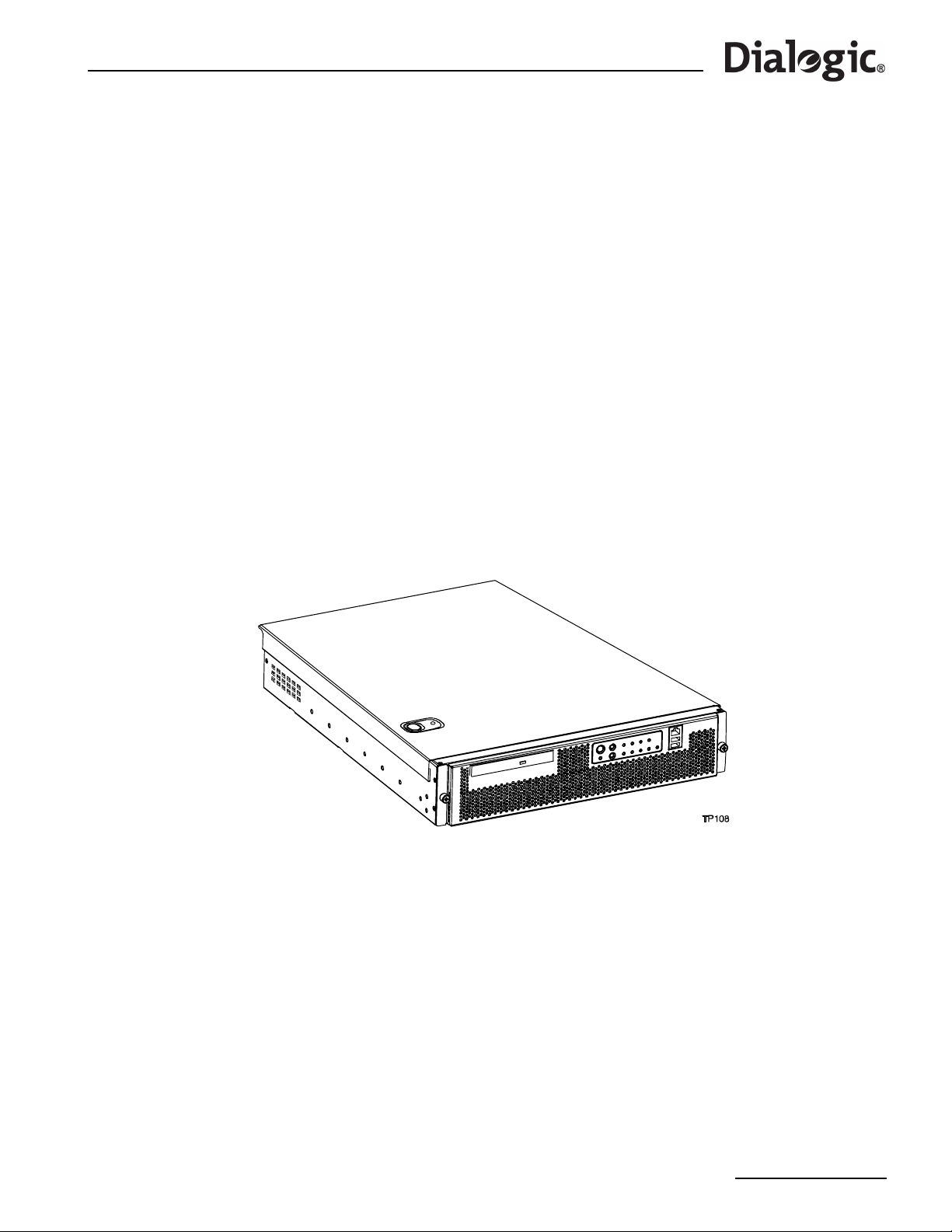
®
Dialogic
SS7G21 and SS7G22 Signaling Servers Hardware Manual Issue 7
Chapter 5: Hardware Description
5.1 Overview
®
The Dialogic
SS7G21 and SS7G22 products are equipped with a Server Board containing dual Intel Xeon
processors with 512 KB L2 cache and 1 GB DRAM DIMM memory. The Server Board also includes a Riser
Board that can contain up to three SS7 Signaling Boards as follows:
• The SS7G21 can contain up to three SPCI2S or SPCI4 boards providing up to 12 SS7 signaling links,
connected via up to 12 interface ports. These ports may be a combination of PCM (T1/E1) interface ports
and V.11 SS7 serial interface ports according to the type of SS7 Signaling Board installed. See
Section 2.7, “SS7 Signaling Boards” on page 12 for more information.
• The SS7G22 can contain up to three SS7HDP boards providing 64 SS7 signaling links per board up to a
system maximum of 128 signaling links. All ports are PCM (T1/E1) interface ports. See Section 2.7, “SS7
Signaling Boards” on page 12 for more information.
These products support a high availability feature option of redundant/hot-swap P ower Supply Modules. Th e
standard product is supplied with a single AC or DC Power Supply Module as determined at time of order.
See Chapter 12, “Part Number Reference” for a list of the available product variants and protocols, plus
expansion options or spare assemblies, and accessories. Rack mounting is described in Section 5.4, “Rack
Mounting Options” on page 34.
See Section 3.10, “Physical Specifications” on page 19 for the product weight and dimensions. Figure 2
presents a front view of the product.
Figure 2. SS7G21 and SS7G22 Hardware
31
Page 32
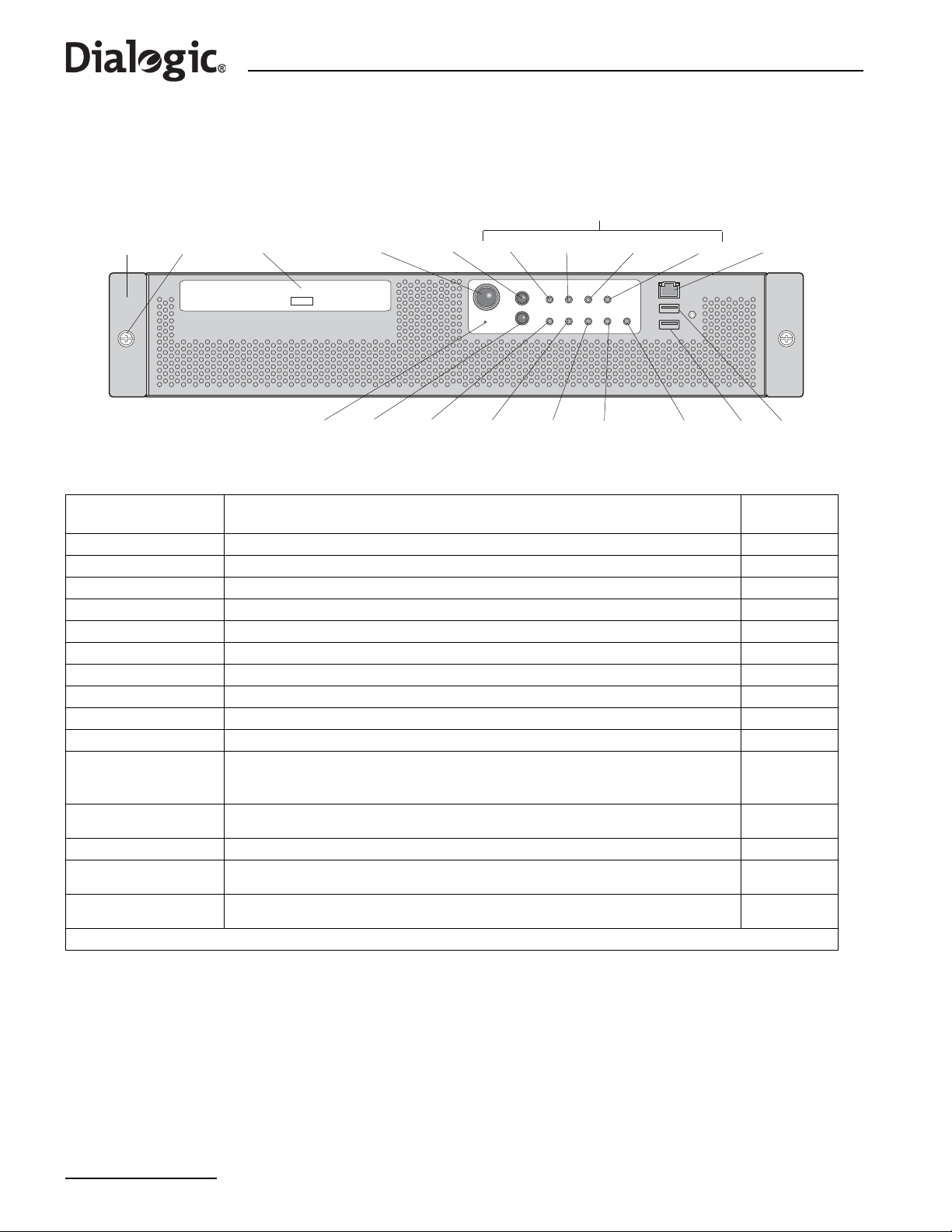
Chapter 5 Hardware Description
5.2 Front Panel
Figure 3 shows the front panel controls, indicators and switches and Table 3 summarizes their functions.
Figure 3. Front Panel Controls, Indicators and Switches
Alarm LEDs
Front
Bezel
Thumb
Screws
CDROM
Drive
Power
Switch
Reset
Switch
CRT MJR MNR PWR
Unused
Port
Not Used ID
Switch
System ID
LED
Activity LED
NIC
ON
LED
Disk 1
Activity LED
Disk 0
Activity LED
USB 2
USB 3
Table 3. Front Panel Control, Indicator and Switch Function Summary
Feature Description
Front bezel Front panel cover N/A
Thumb screws Secure the front bezel to the chassis N/A
Peripheral drive CD-ROM Drive N/A
Power switch Toggles the product power on and off Section 3.9
Reset switch Reboots and initializes the product Section 3.9
CRT Alarm LED † Critical Alarm LED (amber) Section 3.9
MJR Alarm LED † Major Alarm LED (amber) Section 3.9
MNR Alarm LED † Minor Alarm LED (amber) Section 3.9
PWR Alarm LED † Power Alarm LED (amber) Section 3.9
USB 2, USB3 Standard USB ports N/A
Disk 0, Disk 1
Activity LEDs
ON Power LED
NIC Activity LED An activity LED (green). Indicates activity on either ENET 1 or ENET 2. Section 3.9
System ID LED
ID switch
† See Section 3.9, “Controls and Indicators” on page 17 for more information on alarm indications.
Activity LEDs for Hard Disk Drives (HDDs) that indicate one of the following:
• When green, indicates SCSI HDD activity
• When amber, indicates SCSI HDD fault
Power LED (green). When lit continuously, indicates the presence of DC power in the unit.
The LED goes out when the power is turned off or the power source is disrupted.
A system ID LED (white) that can be used to highlight the unit in a rack of units. The LED
can be activated via the ID switch.
T oggles the white System ID LED on the front panel and a blue system ID LED inside the grill
on the back panel. See Figure 4 for the location of the blue LED.
More
Information
Section 3.9
Section 3.9
Section 3.9
Section 3.9
32
Page 33

®
ut
n
DC Power Supply Option Alternative
2
Dialogic
SS7G21 and SS7G22 Signaling Servers Hardware Manual Issue 7
5.3 Back Panel
Figure 4 shows the back panel connectors and Table 4 summarizes their function.
Figure 4. Back Panel Connectors and Indicators
PSU1
AC Power Inp
PSU1
PSU
Filler
Module
OR
PSU2
ENET
LNK B
ENET
LNK A
3
2
1
Alarms
Signaling
Boards
Hot-Swap
Power Supply(s)
3
2
1
AC Power Supply Option Show
USB 1
Unused
Port
ENET 2
Unused
Port
ENET 1
Unused
Port
COM2
(Rear)
USB 0
System ID LED
(Blue, Inside Grill)
Safety
Ground
Studs
DC Power Input
PSU1
Filler
Module
OR
PSU2
Terminal Block
Table 4. Back Panel Connectors and Indicators
Item Description
ENET LNK A, ENET LNK B,
ENET 1 and ENET 2
Alarms Telco alarms DB15 connector. Section 6.8
SS7 Signaling Boards
Hot-Swap Power Supplie(s)
AC Power Input, PSU1 and PSU2 AC power input connectors to Power Supply Modules 1 and 2. Section 6.3
Safety Ground Studs
DC Power Input Terminal Block Two sets of DC power input terminals. Section 6.1
System ID
USB 0, USB 1 Standard USB connectors. N/A
COM2 (Rear) COM2 serial port, RJ-45 connector Section 6.7
Ethernet RJ-45 connectors. ENET LNK A, B are provided by a pre-installed, low-profile
PCI NIC. ENET 1, 2 are provided by the Server Board.
Up to three, each featuring PCM ports and possibly SS7 serial interfaces depending on
the board type. The board positions are marked with numbers, 1 (bottom), 2 (middle)
and 3 (top), to facilitate port identification. These numbers are used when setting the
unit configuration.
Power Supply Module(s): AC and DC Power Supply Modules require different Power
Supply Cages. As standard, the product is supplied with a single Power Supply Module
fitted in the left position (as viewed from the rear), and a filler module in left position.
Redundant, hot-plug configuration is possible by installing a second Power Supply
Module.
T wo 8-32 UNC safety gro und studs for attachment of safety ground conductor to product
for earthing purposes. Use only with DC powered product.
A system ID LED (blue) behind the grill, that can be used to highlight the unit in a rack of
units. The LED is activated by the ID switch on the front panel.
More
Informatio
n
Section 6.6
Section 2.7
Section 2.3
Section 6.2
Section 3.9
33
Page 34

Chapter 5 Hardware Description
5.4 Rack Mounting Options
A number of optional mounting arrangements are available for the Dialogic® SS7G21 and SS7G22 products.
The mounting hardware that you order depends on your application. See Chapter 12, “Part Number
Reference” for information on selecting the correct mounting hardware.
Note: Mounting kits are separately orderable and are not included with the product.
Complete installation instructions are included with each mounting kit. This section gives a brief description
of each type of mounting kit to facilitate the selection of the most appropriate mounting hardware. The basic
rack mount kits available are:
• SS7G20R19LBR – This rack mount kit consists of L-shaped brackets, and permits fixed installation of the
SS7G21 and SS7G22 to 2-post Central Office (CO) type 19” wide racks.
• SS7G20R19MNT and SS7G20R23MNT – These rack mount kits are of a rail construction, with brackets
allowing installation of the SS7G21 and SS7G22 in either 2-post or 4-post racks. The rails are not freesliding rails, and are not intended to allow the product to be accessed in an extended position.
SS7G20R19MNT is for 19” wide standard EIA (universal hole spacing) racks. SS7G20R23MNT is for 23”
wide standard EIA (universal hole spacing) or ETSI (European) racks.
The mounting kits described above have been tested with the DC server chassis that is used in SS7G21 and
SS7G22, and in that application are shown to meet full NEBS-3 specifications, including Seismic zone-4.
The following mount option is also available for use with SS7G21 and SS7G22, but may not provide full
compliance with NEBS-3 requirements:
• SS7G20RSLKIT – This is an enabling kit, rather than a full mounting kit, and requires the independent
procurement of sliding rails such as, Accuride† model # 305-A-LR, or similar. This mounting option is
suited to 19” wide racks.
In addition, there are a number of threaded fixing holes along the sides of the product, and it may be
possible to utilize alternative mounts from other sources. In such cases, the performance is unknown, and
care should be taken not to use excessively long fixing screws.
Warning: Do not rely on rack mounting arrangements for grounding of the product. See WARNINGS on
GROUNDING THE RACK INSTALLATION in Chapter 1, “Warnings and Cautions”. Apply the
Warning for AC power supplies or DC power supplies as appropriate.
34
Page 35

®
Dialogic
SS7G21 and SS7G22 Signaling Servers Hardware Manual Issue 7
Chapter 6: Interfaces
This section provides connector pinout details for all used interface connectors on the SS7G21 and SS7G22.
For locations refer to Section 5.3, “Back Panel” on page 33.
6.1 DC Power Input Terminal Block
A DC Power Input Terminal Block is provided at the rear of the DC-input Power Supply Cage (DC products
only). Connection to a DC power source should be performed only by a qualified service tecnhician.
Details are therefore included in Part II of this manual, see Section 9.2, “Power Supply Related Actions” on
page 50. See also Section 6.2 following.
6.2 Safety Ground Studs for Earthing
Two 8-32 UNC safety ground studs are provided for attachment of safety ground conductor to the product
when using the DC power supply option. Connection of the safety ground conductor should only be
performed by a qualified service tecnhician. Details are therefore included in Part II, see Section 9.2.1,
“Safety Ground Studs, Conductor Installation” on page 51.
6.3 AC Power Input
Two AC power input connectors, type IEC320, are provided at the rear of the Power Supply Cage of AC
powered product. Each connector supplies input power to one of the two Power Supply Module positions,
refer to Section 5.3, “Back Panel” on page 33 for details. These connectors provide the safety ground
connections for the product.
When selecting a suitable power cord(s) for connection to the AC power input(s), ensure that the cords
comply with the AC POWER CORD warning provided in Chapter 1, “Warnings and Cautions”.
When selecting a suitable AC power outlet(s) for connection of the other end of the power cord(s), ensure
that the outlet is earthed, and that it complies with the IF AC POWER SUPPLIES ARE INSTALLED warning in
Chapter 1, “Warnings and Cautions” which covers the following aspects; mains AC power disconnect,
grounding the rack installation, and overcurrent protection.
When in doubt, consult a qualified service tecnhician.
6.4 PCM Interface Ports
Each SS7 Signaling Board provides primary r ate telecommunications (PCM) interfaces, each being
individually configured at run-time under software control to operate as balanced T1 or E1 ports, with
selectable line code and frame format. Depending on the type of SS7 Signaling Board(s) installed, there may
be two (Figure 5) or four (Figure 6 and Figure 7) PCM interfaces per board. For information on setting the
port configurations, see the appropriate SS7G2x <Operating Mode> User Manual. Section 2.10, “Related
Information” on page 13 lists the various user manuals.
Figure 5. PCM Ports on SPCI2S Boards
L4
T1/E1
Ports
L3
AUX
V.11
Ports
35
Page 36
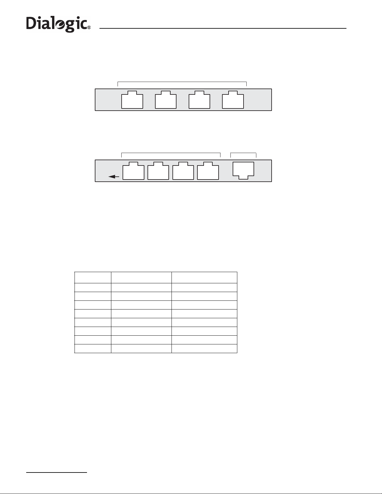
Chapter 6 Interfaces
Figure 6. PCM Ports on SPCI4 Boards
T1/E1
Ports
L4
L3
L2
L1
Figure 7. PCM Ports on SS7HDP Boards
L4
T1/E1
Ports
L1
Unused
Port
ENET
The T1/E1 ports on the SS7 Signaling Boards are Safety Extra Low Voltage (SELV), that is, the apparatus
connects to the outside network via Network Termination units (NT1). Use twisted-pair, screened cables,
grounded at both ends, to ensure the EMC and error-free performance of the product. See also
Section 4.3.3, “Telecommunications” on page 28 for information on potential usage as TNV-1 ports.
The connectors are 8-way RJ45, and are labelled L3 and L4 in Figure 5, or L1 to L4 in Figure 6 and Figure 7.
These labels can be used together with the SS7 Signaling Board position number (see Section 5.3, “Back
Panel” on page 33) to give each port a unique identifier for wiring schedules and unit configuration.
The connector pinout and signal descriptions are shown in Table 5.
Table 5. PCM Interface Ports Connector Pinouts
Pin No Direction Function
1Input Receive
2Input Receive
3 Not applicable No Connection
4Output Transmit
5Output Transmit
6 Not applicable No Connection
7 Not applicable No Connection
8 Not applicable No Connection
6.5 SS7 Serial Interface Ports
SS7 Signaling Boards of type SPCI2S provide two synchronous SS7 serial interface ports. Both ports are
presented in a single 26-way female high density D-type connector, and use V.11 (V.35 compatible)
electrical interface characteristics. See Appendix A.
The connector is labelled Aux in Figure 8 and on the products. Table 6 identifies the ports as A and B. This
can be used with the SS7 Signaling Board position number (see Section 5.3, “Back Panel” on page 33) to
give each port a unique identifier for wiring schedules and unit configuration.
36
Page 37
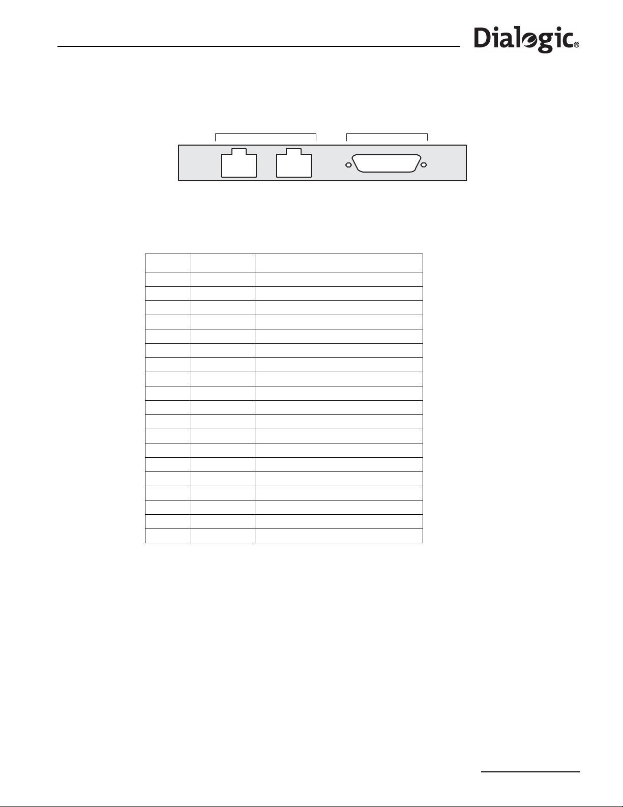
®
Dialogic
SS7G21 and SS7G22 Signaling Servers Hardware Manual Issue 7
Figure 8. SS7 Serial Interface Connector (Aux on SPCI2S)
L4
T1/E1
Ports
L3
AUX
V.11
Ports
The SS7 serial interface ports on the SPCI2S are designated as SELV. Install the ferrite clamp(s), provided
with this product, on each SS7 serial interface port cable, close to the connector backshell, to ensure the
EMC performance of the product. The connector pinout and signal assignment is given in Table 6.
Table 6. SS7 Serial Interface Ports (Dual V.11) Connector Pinouts
Pin No Direction Function
1 Chassis ground
2 Output V.11 Transmit inverted clock Port B
3 Output V.11 Transmit clock Port B
4 Output V.11 Transmit inverted data Port B
5 Output V.11 Transmit true data Port B
6 Input V.11 Receive inverted clock Port B
7 Input V.11 Receive clock Port B
8 Input V.11 Receive inverted data Port B
9 Input V.11 Receive true data Port B
10 Signal ground
11 to 18 No connection
19 Output V.11 Transmit inverted clock Port A
20 Output V.11 Transmit clock Port A
21 Output V.11 Transmit inverted data Port A
22 Output V.11 Transmit true data Port A
23 Input V.11 Receive inverted clock Port A
24 Input V.11 Receive clock Port A
25 Input V.11 Receive inverted data Port A
26 Input V.11 Receive true data Port A
The SS7 serial interface ports may be clocked either by an internally generated clock or by an externally
applied clock. In both cases, the same clock is used for both the Transmit data and the Receive data.
For internal clock operation, use the T r ansmit clock pins and mak e no connection to the R eceive clock pins on
the D-type connector. For external clock operation, connect the clock source to the Receive clock pins on the
D-type connector and make no connection to the Transmit clock pins.
37
Page 38
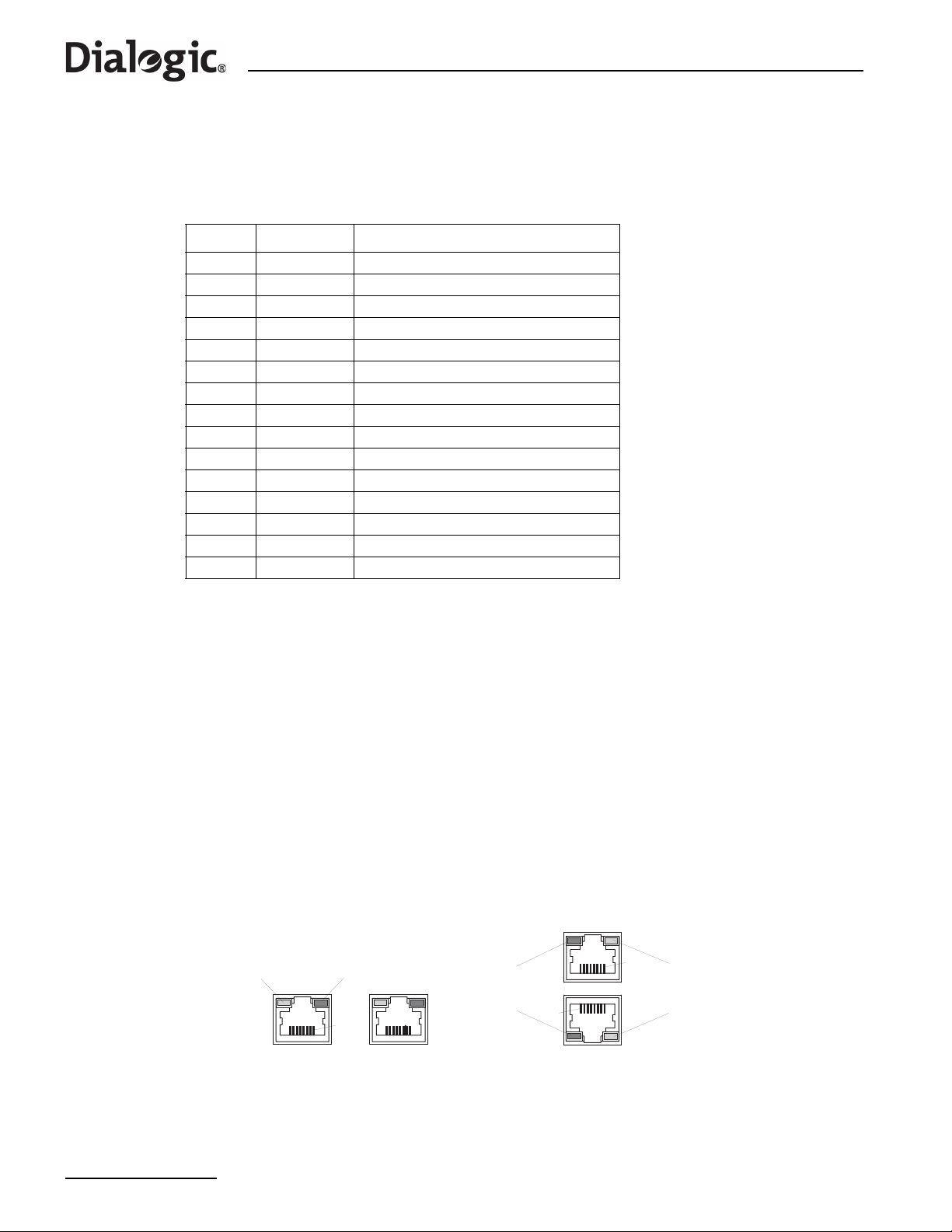
Chapter 6 Interfaces
An SS7 Serial Interface Port Splitter Cable is available, DKL26 (see Chapter 12, “Part Number Reference”).
This is a cable that converts from the dual V.11 26-way high density D connector (detailed in Table 6) to two
15-way male DB15 connectors (detailed in Table 7). When installing this cable, ensure that the ferrite clamp
is fitted close to the 26-way connector.
Table 7. SS7 Serial Interface Port Splitter Cable 15-Way Male DB15 Connector Pinouts
Pin No Direction Function
1 Chassis ground
2 Output V.11 Transmit true data
3 No connection
4 Input V.11 Receive true data
5 No connection
6 Input V.11 Receive true clock
7 Output V.11 Transmit true clock
8 Signal Ground
9 Output V.11 Transmit inverted data
10 No connection
11 Input V.11 Receive inverted data
12 No connection
13 Input V.11 Receive inverted clock
14 Output V.11 Transmit inverted clock
15 No connection
6.6 Ethernet Interfaces
To ensure EMC product regulation compliance for intra-building lightning surges, the product shall only be
used with shielded LAN cables that are grounded at both ends.
T wo pairs of Eth ernet connectors are provided on the SS7G21 and SS7G22. ENET 1 and ENET 2 are provided
by the Server Board, and ENET LNK A and ENET LNK B are provided by a separate low-profile PCI NIC.
Figure 9 shows the Ethernet connectors provided by the PCI NIC and the Server Board.
The Ethernet interface connectors incorporate status LED indicators. The LEDs on the network interface
connectors indicate link/activity on the network and the speed of operation. The green LED, when on,
indicates network connection and when blinking indicates TX/RX activity. The speed LED indicates 1000
Mbps when amber, 100 Mbps when green, and 10 Mbps when off. Table 8 shows the Ethernet connector
pinouts.
A NIC Activity LED (green) on the front panel provides an indication of activity on the ENET 1 or ENET 2
ports. See Section 5.2, “Front Panel” on page 32 for more information.
Figure 9. Ethernet Interfaces Connectors
Speed
Indicator
(Multi-colored)
Link/Activity
Indicator
(Green)
Pin 1
Link/Activity
Indicator
(Green)
Pin 1
Pin 1
Speed
Indicator
(Multi-colored)
38
ENET LNK B (left) and ENET LNK A (right)
Provided by the NIC
ENET 2 (top) and ENET 1 (bottom)
Provied by the Server Board
Page 39
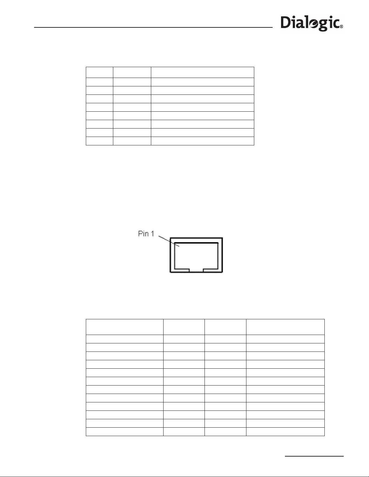
®
Dialogic
SS7G21 and SS7G22 Signaling Servers Hardware Manual Issue 7
Table 8. Ethernet Interface Connector Pinouts
Pin No Direction Function
1OutputTXP
2OutputTXM
3Input RXP
4 Connected to Pin 5
5 Connected to Pin 4
6Input RXM
7GND
8GND
6.7 Serial Port (COM2)
One serial port (COM2, marked 10101) is provided on the back panel. This is an RS232 port using an 8-way
RJ45 connector (see Figure 10). The serial port can be used for configuration and management of the
product. The serial port is designated as SELV.
Note: There is a similar connector on the front panel, but it is not enabled on these products.
Figure 10. Serial Port (COM2) Connector
An RJ45 to DB9 serial cable, DKL29, is supplied with the product. This cable converts from the RJ45
connector pin out to a conventional 9-way female DB9 connector. The pinout of the product serial port
(COM2), and the interconnection of the DKL29 serial cable, is described in Table 9.
Table 9. Serial Port (COM2) Pinouts and DKL29 Serial Cable Interconnection
Signal / Description
Serial Port (product)
RTS - Request to Send 1 No connection
DTR - Data Terminal Ready 2 6 DSR - Data Set Ready
TXD - Transmit Data 3 2 RXD - Receive Data
GND - Ground 4 5 GND - Ground
RIA - Ring Indicator 5 No connection
RXD - Receive Data 6 3 TXD - Transmit Data
DSR - Data Set Ready 7 4 DTR - Data Terminal Ready
CTS - Clear to Send 8 No connection
Connector 1
RJ45 Pin No
No connection 1 DCD – Data Carrier Detect
No connection 7 RTS - Request to Send
No connection 8 CTS - Clear to Send
No connection 9 RIA - Ring Indicator
Connector 2
DB9 Pin No
Signal / Description
(PC etc.)
39
Page 40
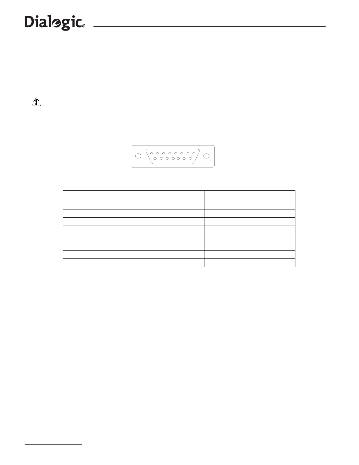
Chapter 6 Interfaces
6.8 Alarms
The alarms port interface is a 15-way male DB15 connector (see Figure 11). This connector allows remote
notification of alarm conditions. Table 10 shows the alarms connector pinouts. Each alarm (Major, Minor,
Critical and Power) is the output of a SPDT relay contact. A common contact with normally open and
normally closed connections is included. Power alarm has just a common and normally open contact outputs.
The alarms port is designated as SELV.
CAUTION
Do not apply more than 60 Volts (maximum) to any pin or combination of pins on the Alarms connector.
Figure 11. Alarms Connector
18
915
Table 10. Alarms Connector Pin-out
Pin No Description Pin No Description
1 Not used – do not connect 9 Minor alarm normally closed
2 Not used – do not connect 10 Minor alarm common
3 Not used – do not connect 11 Major alarm normally open
4 Not used – do not connect 12 Major alarm normally closed
5 Critical alarm normally open 13 Major alarm common
6 Critical alarm normally closed 14 Power alarm normally open
7 Critical alarm common 15 Power alarm common
8 Minor alarm normally open
40
Page 41

®
Dialogic
SS7G21 and SS7G22 Signaling Servers Hardware Manual Issue 7
Part 2: Service Technician’s Guide
41
Page 42

Dialogic
®
SS7G21 and SS7G22 Signaling Servers Hardware Manual Issue 7
42
Page 43

®
Dialogic
SS7G21 and SS7G22 Signaling Servers Hardware Manual Issue 7
Chapter 7: Warnings and Cautions
WARNING
QUALIFIED SERVICE TECHNICIAN OPERATIONS:
Only a qualified service technician is authorized to remove the T op Cove r and to access
any of the components inside the product. Before removing the Top Cover, see
Section 10.1, “Safety: Before Removing the Top Cover” on page 59 and Chapter 7,
“Warnings and Cautions”.
WARNING
ANCHOR THE EQUIPMENT RACK:
The equipment rack must be anchored to an unmovable support to prevent it from
falling over when one or more products are extended in front of the rack on slides. Y ou
must also consider the weight of any other device installed in the rack. A crush hazard
exists should the rack tilt forward which could cause serious injury.
Only use a screwdriver tip to push in lock tabs on rack slides. A pinch hazard exists if
fingers are used for this purpose.
WARNING
TELECOMMUNICATIONS NETWORK CONNECTION:
The telecommunication interfaces of this product are not intended for direct
connection to “outside plant” signal conductors (metallic). The product shall be
isolated, by channel banks or office repeaters, from any connections to network or
terminal equipment, that lie outside of the same building. The telecommunication
interface connections are considered to be, and meet the requirements of, SELV
circuits (not TNV). Refer also to any region specific regulatory requirements of network
connection in Chapter 4, “Regulatory Specifications and Declarations”.
Note that for some geographic regions, and subject to limitations, the T1/E1 ports of
Dialogic
®
SS7HDP boards in Dialogic® SS7G22 products may be connected to “outside
plant” signal conductors, and therefore become TNV-1 circuits. See Section 4.3.3,
“Telecommunications” on page 28 for more details.
43
Page 44

Chapter 7 Warnings and Cautions
WARNING
IF AC POWER SUPPLIES ARE INSTALLED:
MAINS AC POWER DISCONNECT:
The AC power cord(s) is considered the mains disconnect for the product and must be
readily accessible when installed. If the individual product power cord(s) will not be
readily accessible for disconnection then you are responsible for installing an AC power
disconnect for the entire rack unit. This main disconnect must be readily accessible,
and it must be labelled as controlling power to the entire rack unit, not just to this
product. To remove all power, two AC cords must be removed.
GROUNDING THE RACK INSTALLATION:
To avoid the potential for an electrical shock hazard, you must include a third wire
safety ground conductor with the rack installation. If the product power cord is
plugged into an AC outlet that is part of the rack, then you must provide proper
grounding for the rack itself. If the product power cord is plugged into a wall AC outlet,
the safety ground conductor in the power cord provides proper grounding only for this
product. Y ou must provide additional, proper gro unding for the rack and other dev ices
installed in it.
OVERCURRENT PROTECTION:
The product is designed for an AC line voltage source with up to 20 Amps of
overcurrent protection per cord feed. If the power system for the equipment rack is
installed on a branch circuit with more than 20 Amps of protection, you must provide
supplemental protection for the product. The overall current rating of the product
configured with two power supplies is less than 2.5 Amps.
WARNING
AC POWER CORD:
Do not attempt to modify or use an AC power cord that is not the exact type required.
You must use a power cord that meets the following criteria:
1. Rating: For U.S./Canada cords must be UL Listed/CSA Certified type SJT, 18-3
AWG. For outside U.S ./Canada cords must be flexible harmonized (<HAR>) or VDE
certified cord with 3 x 0.75mm conductors rated 250 VAC.
2. Connector, wall outlet end: Cords must be terminated in grounding-type male plug
designed for use in your region. The connector must have certification marks
showing certification by an agency acceptable in your region and for U.S. must be
rated 125% of overall current rating of the product.
3. Connector, product end: The connectors that plug into the AC receptacle on this
product must be an IEC 320, sheet C19, type female connector.
4. Cord length: Cords must be less than 4.5 meters (14.76 feet) long.
44
Page 45

Dialogic
®
SS7G21 and SS7G22 Signaling Servers Hardware Manual Issue 7
WARNING
IF DC POWER SUPPLIES ARE INSTALLED:
ISOLATION:
The product with DC input is to be installed in a Restricted Access Location in
accordance with articles 110-16, 110-17 and 110-18 of the National Electric Code,
ANSI/NFPA 70. The DC source must be electrically isolated by double or reinforced
insulation from any hazardous AC or DC source. The DC source must be capable of
providing up to 200 W of continuous power per feed pair. Connection to a DC source
should only be performed by a QUALIFIED SERVICE TECHNICIAN.
MAIN DC POWER DISCONNECT:
You are responsible for installing a properly rated DC power disconnect for the entire
rack unit. This DC power disconnect must be readily accessible, and it must be labelled
as controlling power to the entire rack unit, not just to this product.
GROUNDING THE RACK INSTALLATION:
T o avoid the potential for an electrical shock hazard, you must reliably connect a safety
ground conductor to the product. The safety ground conductor must be a minimum
14AWG connected to the safety ground studs on the rear of the product, with a closed
two-hole crimp terminal. The nuts on the safety ground stud should be installed with a
10 in/lbs torque. The safety ground conductor provides proper grounding only for this
product. You must provide additional, proper grounding for the r ack and other devices
installed in it.
OVERCURRENT PROTECTION:
Overcurrent protection circuit breakers must be provided as part of each host
equipment rack and must be installed between the DC source and this product. The
branch circuit protection shall be rated minimum 75 VDC, 10 Amps maximum per feed
pair. If the DC power system for the equipment rack is installed with more than 10
Amps of protection, you must provide supplemental protection for this product. The
overall current rating of this product configured with two power supplies is less than
4Amps.
45
Page 46

Chapter 7 Warnings and Cautions
Caution
Anti-Static Handling Procedures:
The product contains Electrostatic Sensitive Devices (ESDs), which may be
permanently damaged if incorrectly handled. If modules are removed from the chassis
they must be handled in accordance with appropriate anti-static handling procedures.
Refer to IEC61340-5-1 Electrostatics - Part 5-1: Protection of electronic devices from
electrostatic phenomena - General requirements for further details. If you are not
familiar with ESD precautions, visit
http://www.dialogic.com/support/hwinstall/esd.pdf to learn more.
Caution
Temperature:
The temperature, in which this product operates when installed in an equipment rack,
must not go below 5 °C (41 °F) or rise above 40 °C (104 °F). Extreme fluctuations in
temperature can cause a variety of problems in your product.
Caution
Ventilation:
The equipment rack must provide sufficient airflow to the front of the product to
maintain proper cooling. The rack must also include ventilation sufficient to exhaust a
maximum of 790 BTUs per hour for this product. The rack selected and the ventilation
provided must be suitable to the environment in which the product will be used.
46
Page 47
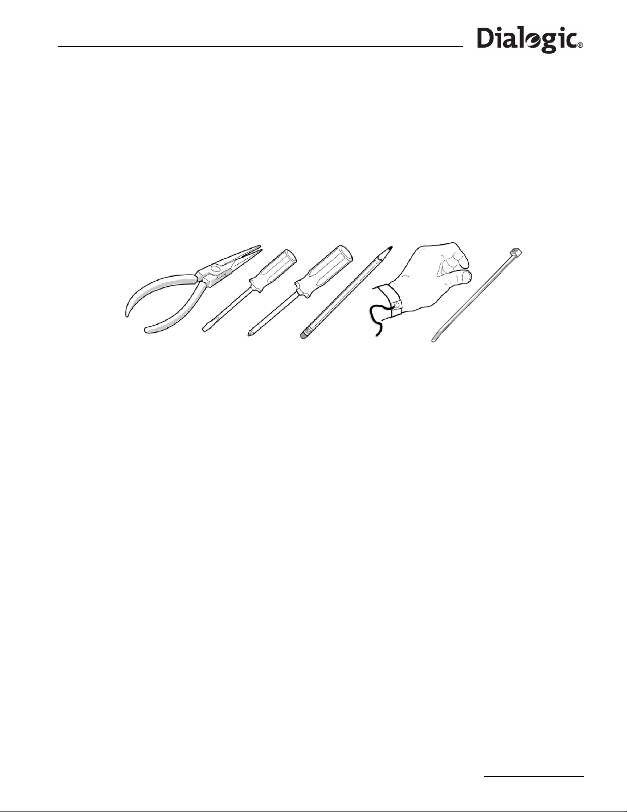
®
Dialogic
SS7G21 and SS7G22 Signaling Servers Hardware Manual Issue 7
Chapter 8: Tools and Supplies Needed
Procedures in Part II of this manual require the following tools and supplies (see Figure 12):
• Jumper-removal tool or needle-nosed pliers
• Small flat-bladed screwdriver
• Phillips (cross-head) screwdriver (#2)
• Pen or pencil
• Anti-static wrist strap and conductive foam pad (recommended)
• Cable tie
Figure 12. Tools and Supplies Needed
Note: Blue-colored items (such as handles, buttons, and screws) represent service touch points.
Remove power from system before servicing these components. Green-colored items (such as
handles, levers, and buttons) represent hot-pluggable components.
Record the model and serial number of the product, all installed options, and any other pertinent information
specific to the product.
A list of part numbers of available spare parts is provided in Chapter 12, “Part Number Reference”.
47
Page 48

Chapter 8 Tools and Supplies Needed
48
Page 49

®
Dialogic
SS7G21 and SS7G22 Signaling Servers Hardware Manual Issue 7
Chapter 9: Product Installation and Hot-Swap Actions
This chapter describes actions that must be performed by a qualified service technician, but which do not
require the removal of the Top Cover of the product. Before commencing these procedures, read Chapter 7,
“Warnings and Cautions” in Part II of this manual.
Do not proceed to remove the Top Cover without consulting Section 10.1, “Safety: Before Removing the Top
Cover” on page 59 and Section 10.2, “Warnings and Cautions: Working Inside the Product” on page 59.
9.1 Installation Overview
®
Installation of a Dialogic
shown. References to more detailed task descriptions are provided where appropriate.
To install an SS7G21 or SS7G22 unit, proceed as follows:
1. Read all warnings and cautions. See Chapter 7, “Warnings and Cautions” for details.
2. Choose the right product to suit the application taking into account the number and type of interface
ports, the link processing capability, and whether the product needs to be AC- or DC-powered. See
Section 12, “Part Number Reference” on page 79 for more information on the available product variants.
3. Install any hardware options purchased, for example, an extra PSU module (see Section 9.2, “Power
Supply Related Actions” on page 50) or mounting rails for the product (see Section 5.4, “Rack Mounting
Options” on page 34 for more information).
4. Physically install the product in an equipment rack or as a free standing unit.
5. Connect the product to ground:
— When installing a DC-powered product, see Section 9.2.1, “Safety Ground Studs, Conductor
Installation” on page 51.
— When installing an AC-powered product, the ground connection and power connection are part of the
same operation. See step 6 below.
6. Connect the power source:
— When installing a DC-powered product for the first time, see Section 9.2.2, “DC Power Supply
Module, Initial Connections” on page 51. When replacing a product, see Section 9.2.3, “DC Power
Supply Module, Transferring Connections” on page 53.
— When installing an AC-powered product, see Section 6.3, “AC Power Input” on page 35.
In either case, ensure that the chosen power source meets the relevant requirements for “MAINS AC/DC
POWER DISCONNECT” and “OVERCURRENT PROTECTION” as described in Chapter 7, “Warnings and
Cautions”.
7. Connect line interface, Ethernet interface, and alarm cables. See Chapter 6, “Interfaces” for connector
details and pinout information for the various interfaces.
— T o ensure that you av oid EMC problems with the installation, comply with the instruction s and advice
given in Section 4.3.2, “EMC” on page 28.
— For safety and operational aspects affecting network connections, comply with the advice given in
Section 4.3.3, “Telecommunications” on page 28 and any region-specific requirements in
Section 4.2.3, “FCC Part 68 Statement - USA” on page 26,
Section 4.2.4, “Telecommunications Attachment Notice - Canada” on page 27,
Section 4.2.6, “Telecommunications Notice - Australia / New Zealand” on page 27,
Section 4.2.7, “Telecommunications Notice - Taiwan” on page 27.
8. Power up the product.
9. Complete the following software and configuration steps, all of which are fully described in the
appropriate SS7G2x <Operating Mode> User Manual. Section 2.10, “Related Information” on page 13
lists the various user manuals.
— Check whether a software download and upgrade is required.
— Install optional software licenses.
— Set the IP addresses of the unit.
— Enable the selected Operating Mode (SIU, DSC or SGW).
Note: The SIU Operating Mode is enabled by default.
SS7G21 or SS7G22 product involves the following tasks performed in the order
49
Page 50

Chapter 9 Product Installation and Hot-Swap Actions
— Configure the product.
10.When installation is complete and the system is operating as intended, consider if you will want to install
a replacement Hard Disk Drive (HDD) in the future. If you do, now is an ideal time to perform a backup
of the System Configuration, which is a necessary step before the HDD can be re placed. For information
on how to back up the System Configuration, read the instructions in Section 9.3.1, “Backing up the
System Configuration” on page 56.
Note: The installer or developer must ensure that the product configuration, and any related
application that is running, provides an implementation that complies with the services offered
by the local Public Switched Telephone Network (PSTN) operator. In case of doubt, network
specifications must be consulted.
9.2 Power Supply Related Actions
There are many different actions that may be required with regard to the Power Supply Modules and their
connections. These can be found in the sub-sections below, or referenced from them, as follows:
• Product Installation, Power Wiring for DC Products
This consists of two essential actions, and one optional action.
— First connect the Safety Ground Studs as described in Section 9.2.1.
— Carry out initial wiring of a DC Power Supply Module as described in Section 9.2.2.
— If the dual redundant option is required, order and install a second DC Power Supply Module.
Installation of the second module is described below.
• Product Installation, Power Wiring for AC Products
This consists of one essential actions, and one optional action.
— Connection of the AC-input Power Supply Cage is described in Section 9.2.4.
— If the dual redundant option is required, order and install a second AC Power Supply Module.
Installation of the second module is described below.
Note: There is no need to connect the Safety Ground Studs on AC powered products, as the Safety
Ground is provided in the mains cords.
• Second Power Supply Module Installation in DC Products
This operation is basically the same, whether it is carried out at the time of initial installation of the basic
product, or if it is decided to add a second DC Power Supply Module at a later date. The benefits of using
a dual-redundant power supply configuration are described in Section 2.3, “Power Supplies” on page 12.
Removal of the filler module is basically the same as removing a DC Power Supply Module as described in
Section 9.2.5, which also covers the insertion of the DC Power Supply Module, including the use of the
'latches'. Take this opportunity to check that the Safety Ground Stud connection is in good order, as
described in Section 9.2.1. Wiring of the second module follows the description in Section 9.2.2.
• Second Power Supply Module Installation in AC Products
This operation is basically the same, whether it is carried out at the time of initial installation of the basic
product, or if it is decided to add a second AC Power Supply Module at a later date. The benefits of using
a dual-redundant power supply configuration are described in Section 2.3, “Power Supplies” on page 12.
Removal of the filler module is basically the same as removing an AC Power Supply Module as described
in Section 9.2.6, which also covers the insertion of the AC Power Supply Module, including the use of the
'latches'. Connection for the second module simply requires both mains cords to be used on the AC-input
Power Supply Cage, as described in Section 9.2.4.
• Replacement of Power Supply Module in DC Products
The general actions required, such as (un)latching, removal and insertion of modules, are described in
Section 9.2.5.
Transferring of the connections from the 'removed' module, to the 'replacement' module, are described
in Section 9.2.3.
If replacing a failed module, it is possible that the relevant fuse may need replacement. It should be
possible to determine if this is necessary from the LED indication on the new module.
50
Page 51

®
Dialogic
SS7G21 and SS7G22 Signaling Servers Hardware Manual Issue 7
• Replacement of Power Supply Module in AC Products
The general actions required, such as (un)latching, removal and insertion of modules, are described in
Section 9.2.6.
The connections are unaffected by AC Module replacement.
If replacing a failed module, it is possible that the relevant fuse may need replacement. It should be
possible to determine if this is necessary from the LED indication on the new module.
9.2.1 Safety Ground Studs, Conductor Installation
T w o 8-32 UNC safety ground studs are provided for attachment of a safety ground conductor to the product.
These are for use only with DC powered product. Connection of a safety ground conductor should only be
performed by a qualified service technician.
When connecting the safety ground conductor, ensure that it complies with the WARNING – IF DC POWER
SUPPLIES ARE INSTALLED, sub-section GROUNDING THE RACK INSTALLATION in Chapter 7, “Warnings and
Cautions”.
The safety ground conductor must be a minimum 14AWG. To connect the safety ground conductor to the
safety ground studs with a two-hole crimp terminal lug:
1. Place an 8-32 UNC nut on one safety ground stud and tighten to 10 in-lb.
2. Place the safety ground conductor terminal lug on the safety ground studs.
3. Place another 8-32 UNC nut on the same safety ground stud so that the safety ground conductor
terminal lug is between the two nuts and tighten the second nut to 10 in-lb.
When installing the product in locations other than telecommunications centres, ensure that the safety
ground conductor is less than 3 metres in length.
The two-hole crimp terminal lug must have a hole spacing of 5/8-inch, and must suit the conductor size in
use, for example, Panduit
®
part number LCD8-10A-L, which suits 8AWG conductor.
9.2.2 DC Power Supply Module, Initial Connections
For DC powered products, each Power Supply Module is provided with its own DC power input terminal block,
mounted directly on the rear of the module. Connection to a DC source should only be performed by a
qualified service technician. See also Section 9.2.1, “Safety Ground Studs, Conductor Installation” on
page 51. See Figure 13 for the location of the terminal block on DC Power Supply Modules.
51
Page 52
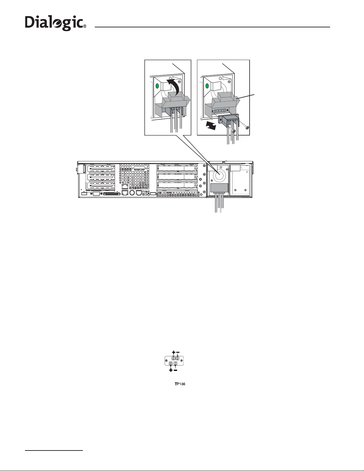
Chapter 9 Product Installation and Hot-Swap Actions
Figure 13. DC Power Supply Module Terminal Block
D
DC Power Supply Module
Terminal Block Connections
Insulating
Cover
The product is supplied with an insulating cover over the terminal block. To gain access to the terminals,
apply gentle pressure to flip up the cover, while using a small flat blade screwdriver to unlatch each side in
turn. When the wiring is complete the cover must be flipped down, and securely latched at both sides. All
wiring terminals connected to the DC power input terminal block must be insulated, with no accessible bare
metal when the cover is closed.
When installing a second Power Supply Module to provide the redundant/hot-swap facility, each module
needs to be independently connected to a separately-fused DC source.
Each DC power input terminal block has two positive and two negative terminals as shown in Figure 14.
Normally , only one pair (+ and -) on each module need to be connected to the external DC source, but if you
require to operate on dual-redundant external DC sources, then both pairs shall be connected to separatelyfused external DC sources. Note however that the two pairs are directly connected together within the
module, and so the type of external source has to be chosen accordingly . Although the terminals are directly
connected, they must not be used to connect onward the DC source to another example of this, or any other,
product (this could result in exceeding the current rating of wiring, fuses, terminal block or internal
connections, and also the onward connection would be disrupted during hot-swap of a PSU module).
Figure 14. DC Power Input Connector
The terminal block accepts standard terminal lugs that accept 14 AWG wire gauge, for example, Network™
stock # 81N1501 type CRS-TO-1406-HT. The width (labeled ‘W’ in Figure 15) of the lug can be no larger than
0.25 inches.
52
Page 53

®
Dialogic
SS7G21 and SS7G22 Signaling Servers Hardware Manual Issue 7
Figure 15. DC Power Terminal Lug
When selecting an appropriately sized power wire, consider the power rating of the product, and the length
of the cable run. When installing the product in locations other than telecommunications centres, ensure that
the cables connecting the DC power input, and the safety ground conductor, are less than 3 metres in
length.
When selecting a suitable DC power source for connection to, ensure that it complies with the WARNING – IF
DC POWER SUPPLIES ARE INSTALLED warning in Chapter 7, “Warnings and Cautions”. This co vers the
following aspects; isolation, installation in a restricted-access location, main DC power disconnect, grounding
the rack installation, and overcurrent protection.
9.2.3 DC Power Supply Module, Transferring Connections
When replacing a DC Power Supply Module, the terminal block, with wires attached, can be removed from
the faulty Power Supply Module and assembled to the replacement Power Supply Module as follows:
1. Remove the two screws that secure the terminal block to the Power Supply Module and pull the terminal
block away from the module. See Figure 13 on page 52.
Note: Removing the two screws also frees the terminal block cover, but it can be retained by attaching
it to the removed terminal block.
2. Remove the faulty Power Supply Module from the chassis.
3. Install the replacement Powe r Supply Modu le. See Section 9.2.5, “Replacing a DC Power Supply Module”
on page 53.
4. On the newly installed Power Supply Module, lift the insulating cover on the terminal block to access the
two screws that secure the terminal block to the chassis.
5. Remove the two screws and carefully pull the terminal block away from the Power Supply Module.
6. Align the old terminal block (with wires attached) with the terminal block receptacle on the new Power
Supply Module and carefully push the terminal block into the Power Supply Module.
7. Secure the terminal block in position using the two securing screws. See Figure 13 on page 52.
8. Close and latch the insulating cover so that it covers the terminals.
9.2.4 AC-input Power Supply Cage, Connection
Two AC power input connectors, type IEC320, are provided at the rear of the Power Supply Cage of AC
powered product. Connection to an AC power outlet is covered in Part I, Section 6.3, “AC Power Input” on
page 35 (it is not essential for it to be performed by a qualified service technician).
9.2.5 Replacing a DC Power Supply Module
Observe the following cautions:
53
Page 54
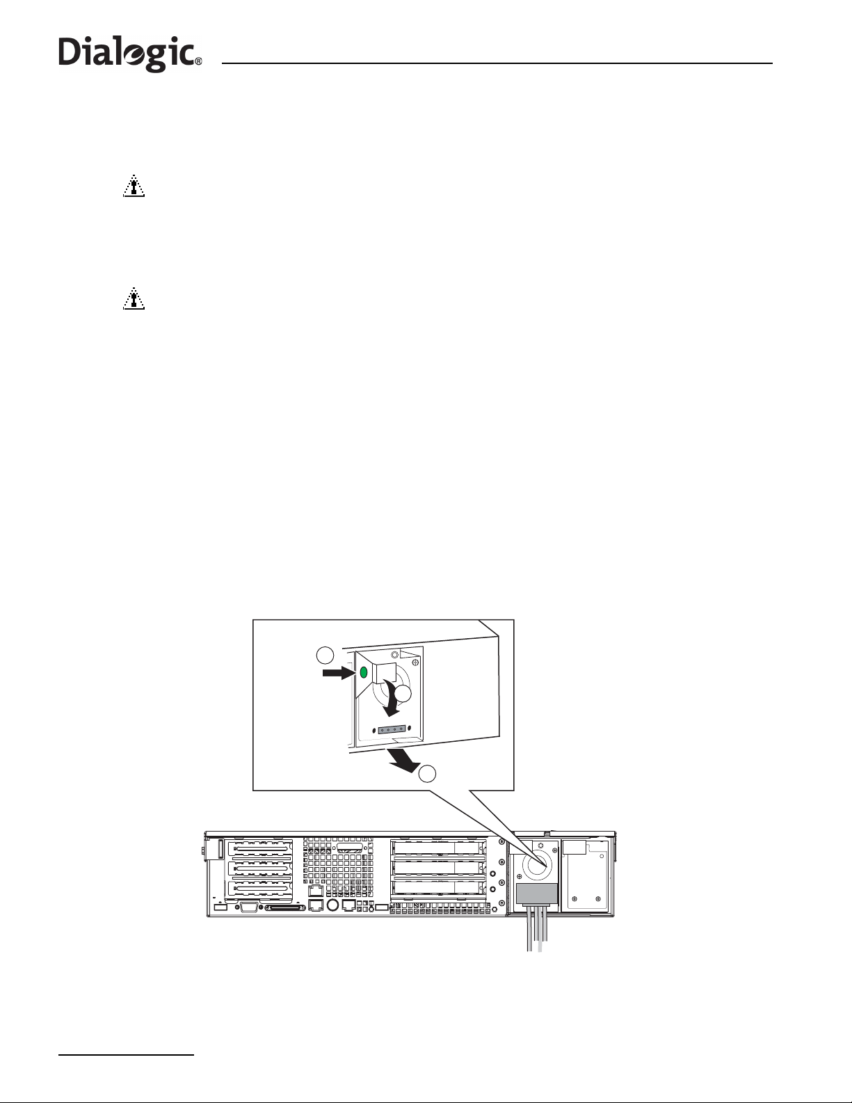
Chapter 9 Product Installation and Hot-Swap Actions
Note: For DC powered products, the power source should be disconnected from any module while it is
being removed or installed. When hot-swap functionality is required, ensure that one module
remains installed, connected, and powered at all times.
CAUTION 1
Both module positions should have either a Power Supply Module or a filler module
installed whenever the product is operational. Otherwise the cooling efficiency of the
remaining module is impaired. During a Hot-swap operation there is a brief interval
when one position is empty. If the replacement Power Supply Module is not
immediately available, then a filler module must be installed.
CAUTION 2
AC Power Supply Modules cannot be used in the DC-input Power Supply Cage, and
similarly, DC Power Supply Modules cannot be used in the AC-input P ower Supply
Cage. The correct product variant/Power Supply Module must be specified at time of
ordering, see Chapter 12, “Part Number Reference”.
Install or replace a DC Power Supply Module as follows:
1. Remove the terminal block with wires attached from the faulty DC Power Supply Module as described in
Section 9.2.3, “DC Power Supply Module, Transferring Connections” on page 53.
2. Press the green button on the DC Power Supply Module (labeled A in Figure 16).
3. Rotate the green handle downward (labeled B in Figure 16).
4. Using the green handle, pull the Power Supply Module or filler module outward (labeled C in Figure 16).
5. When installing/reinserting a DC Power Supply Module, make sure the green handle is in the downward
position before sliding the module into the Power Supply Cage. Press the module firmly into place, then
rotate the handle upward to complete the insertion.
6. Assemble the terminal block (with wires attached) to the replacement DC Power Supply Module as
described in Section 9.2.3, “DC Power Supply Module, Transferring Connections” on page 53.
Figure 16. Unlocking and Removing the DC Power Supply Module
A
B
Note: Power supply module shown
with terminal block removed
9.2.6 Replacing an AC Power Supply Module
C
Observe the following cautions:
54
Page 55
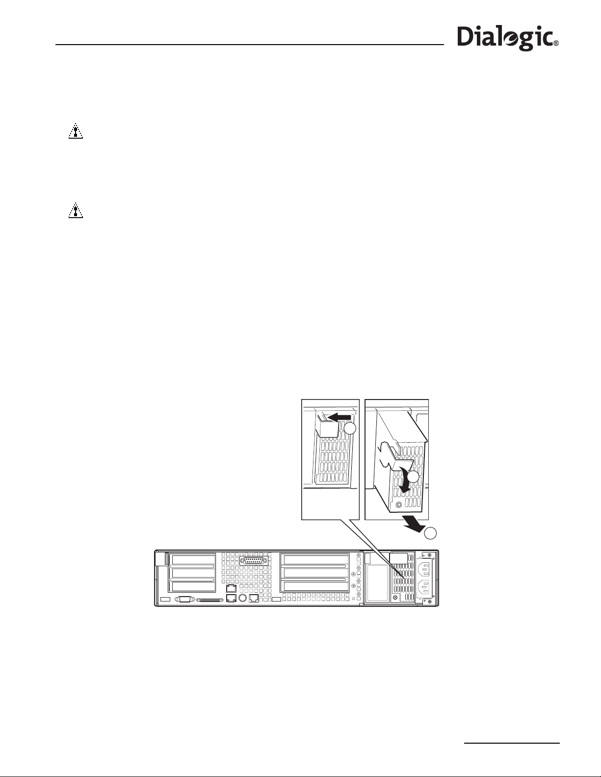
®
Dialogic
SS7G21 and SS7G22 Signaling Servers Hardware Manual Issue 7
Note: For AC powered products, the power source may be connected and turned on during Power
Supply Module installation/replacement. When hot-swap functionality is required two AC power
cords must be connected.
CAUTION 1
Both module positions should have either a Power Supply Module or a filler module
installed whenever the product is operational. Otherwise the cooling efficiency of the
remaining module is impaired. During a Hot-swap operation there is a brief interval
when one position is empty. If the replacement Power Supply Module is not
immediately available, then a filler module must be installed.
CAUTION 2
AC Power Supply Modules cannot be used in the DC-input Power Supply Cage, and
similarly, DC Power Supply Modules cannot be used in the AC-input Power Supply
Cage. The correct product variant/Power Supply Module must be specified at time of
ordering, see Chapter 12, “Part Number Reference”.
Install or replace an AC Power Supply Module as follows:
1. Squeeze the green locking tab on the AC Power Supply Module (labeled A in Figure 17).
2. Rotate the green handle downward (labeled B in Figure 17).
3. Using the green handle, pull the Power Supply Module or filler module outward (labeled C in Figure 17).
4. When installing/reinserting a Power Supply Module, make sure the green handle is in the downward
position before sliding the module into the Power Supply Cage. Press the module firmly into place, then
rotate the handle upward to complete the insertion.
Figure 17. Unlocking and Removing an AC Power Supply Module
AC power supply module shown
A
B
C
9.3 Hard Disk Drive (HDD) Replacement
The SS7G20SHDD Spare Hard Disk Drive for Dialogic® SS7G21 and SS7G22 Signaling Servers, consists of a
spare hard disk drive, which contains the operating software for use with a SS7G2x Signaling Server. It
allows the recovery of systems that have suffered HDD failure, but is subject to the pre-condition that the
system operator must have prepared a System Configuration backup in advance of the HDD failure. It is
recommended that this is done once a system installation is complete and operating as intended, and should
be repeated each time significant configuration or license changes are made.
The SS7G20SHDD is preinstalled with SS7G2x Software Distribution V4.04 or later.
55
Page 56
Chapter 9 Product Installation and Hot-Swap Actions
An SS7G20SHDD may be used in any SS7G2x Signaling Server, however, it requires a valid System License
for that system. The process for making a backup of the System License and additional configuration files is
described below.
Note: Only one hard disk may be used in an SS7G2x at any time. Using more than one may adversely
affect system operation.
A Hard Disk Drive replacement process occurs in three stages:
1. “Backing up the System Configuration” on page 56.
2. “Replacing the Hardware” on page 56.
3. “Restoring the System Configuration” on page 57.
9.3.1 Backing up the System Configuration
Before the Hard Disk Drive can be replaced, a backup of the system configuration, System License, protocol
licenses and operating software must exist.
In systems running SS7G2x Software V4.04 or later, the system takes a copy of these files and stores them
syslog subdirectory of the siuftp account at startup. These files may be recovered using FTP and
in the
archived by transferring them to an ISO9660 format CD-ROM ready for restoration at a later date.
Table 11 lists the files backed up to the
Table 11. Files Backed Up to the syslog Subdirectory at Startup
File Type Description
sgw.tgz Binary A binary file containing the current operating software on the system.
sgw.lic ASCII
modcap Binary
config.CF1 Binary
config.txt ASCII The text configuration file for a SIU, if present.
SDC.CF3 Binary The binary configuration file for a SGW, if present.
SDC.CF4 Binary The binary configuration file for a DSC, if present.
9.3.2 Replacing the Hardware
WARNING
No more than one hard disk drive should be fitted in the SS7G2x. The hard disk drive
should only be fitted in the left-hand Chassis slot.
Note: The diagram below shows the numbers and arrows on the right-hand Chassis slot. This is for
illustration only, and the instructions to use the left-hand Chassis slot must be followed.
syslog subdirectory at startup.
A text file containing the current software licens es active on the system,
if present.
A binary file containing a system license allowing SS7G2x operating
software to function on this particular system.
A binary configuration file containing dynamically configurable data that
is common to all modes of operation. For example, parameters set by
the CNSYS command would be stored in this file.
The steps below describe the actions required to replace the hardware. The SS7G2x must be powered-off
before replacing the hardware.
1. To remove the bezel, loosen the two captive screws and lift the bezel outwards.
56
Page 57
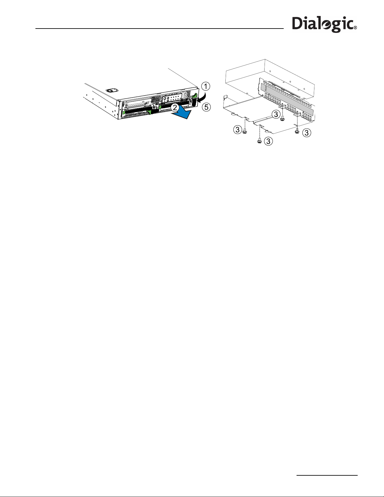
®
Dialogic
SS7G21 and SS7G22 Signaling Servers Hardware Manual Issue 7
Figure 18. Replacing the Hard Disk Drive
2. T o unlock the carrier from the chassis, press the green tab on (horizontal) lever to the right to unlock the
lever. Rotate lever 90 degrees clockwise to a vertical position, to disconnect the SCSI drive connection.
3. To remove the carrier , press to the right the green latch at the left end of the carrier handle, allowing the
handle to swing out, and the carrier to be unlocked. Pull on the handle in the direction of the arrow to
remove the HDD carrier from the chassis.
4. To install the HDD in the carrier, install, then tighten four 6-32 UNC screws to secure the HDD to carrier.
5. To reinstall the HDD carrier into the chassis, place the carrier fully into the chassis slot, and press the
handle flat to the front, making sure the green latch clicks into place to secure the carrier to the chassis.
6. T o engage the HDD SCSI connections, ro tate the green lever 90 degrees counterclockwise to a horizontal
position. Press gently down on the green area until the locking tab pops out to the left. To ensure the
drive is fully engaged with the SCSI connector, use firm but gentle pressure on the green area. On
releasing the pressure, check that the lever is locked in the horizontal position.
7. Finally, replace the bezel and tighten the two captive screws.
9.3.3 Restoring the System Configuration
Once the new SS7G20SHDD has been installed, the previous system configuration should be restored. The
ISO9660 format CD-ROM containing backup of the system configuration, System License, protocol licenses
and operating software, which was described in Section 9.3.1, “Backing up the System Configuration” on
page 56, should be inserted into the CD-ROM drive. The system will install the backup files from the CD-ROM
at startup and may automatically restart if a different version of the SS7G2x Software Distribution is being
installed.
After the restoration process has completed, the CD-ROM should be removed to prevent the backup
configuration from overwriting subsequent configurations.
57
Page 58

Chapter 9 Product Installation and Hot-Swap Actions
58
Page 59

®
Dialogic
SS7G21 and SS7G22 Signaling Servers Hardware Manual Issue 7
Chapter 10: Working Inside the Product
This chapter describes actions that must be performed by a qualified service technician, and which
require the removal of the Top Cover from a Dialogic® SS7G21 or SS7G22 product. Before commencing
these procedures, read the Chapter 7, “Warnings and Cautions”, the safety advice in Section 10.1, and the
warnings and cautions, in Section 10.2. The removal of the Top Cover is described in Section 10.3, and the
internal layout is described in Section 10.4. The procedures that follow describe actions on components
internal to the product.
10.1 Safety: Before Removing the Top Cover
Before removing the Top Cover at any time to work inside the product, observe these safety guidelines:
1. Turn off all peripheral devices connected to the product.
2. Power down the product by pressing and holding the power switch ( ) on the front of the chassis for
several seconds. After the product shuts down and the fans stop rotating, unplug or disconnect the
power cords to remove standby power from the product.
3. Label and disconnect all peripheral cables and all telecommunication lines connected to connectors or
ports on the back of the product.
10.2 Warnings and Cautions: Working Inside the Product
These warnings and cautions apply whenever the Top Cover of the product is removed.
Only a qualified service technician should remove the Top Cover of the product. Only a qualified service
technician should integrate, configure, or service the product.
WARNING
POWER SWITCH
Shutting down the product with the Power switch on the front of the product does not
remove all power from the product. To remove all power from the product, you must
also unplug or disconnect the power cords from the product. Unplugging or
disconnecting the power cords from the product removes the +12 Volt standby power
that is present when the product is powered down (standby).
WARNING
HAZARDOUS CONDITIONS, POWER SUPPLY
Hazardous voltage, current, and energy levels are present inside the power supply.
There are no user-serviceable parts inside the power supply; only technically qualified
personnel should do servicing.
WARNING
HAZARDOUS CONDITIONS, DEVICES AND CABLES
Hazardous electrical conditions may be present on power, telephone, and
communication cables. Turn off the product and unplug or disconnect power cords,
telecommunications systems, networks, and modems attached to the product before
removing the Top Cover. Otherwise, personal injury or equipment damage can result.
WARNING
HAZARDOUS CONDITIONS, PROCESSORS AND POWER SUPPLIES
Thermal conditions may be present in the processor or memory complex. Allow all fans
to continue to run until they shut down on their own after power has been turned off.
After the fans stop rotating, you can unplug or disconnect the power cords.
59
Page 60
Chapter 10 Working Inside the Product
Caution
Electrostatic Discharge (ESD) and ESD Protection:
ESD can damage Hard Disk Drives (HDDs), boards, and other parts. We recommend
that you do all procedures in this chapter only at an ESD-protected workstation. If one
is not available, provide some ESD protection by wearing an anti-static wrist strap
attached to chassis ground (any unpainted metal surface) on your product when
handling parts.
Caution
ESD and Board Handling:
Always handle boards carefully. They can be extremely sensitive to ESD. Hold boards
only by their edges. After removing a board from its protective wrapper or from the
product, place it on a grounded surface free of static electricity. Do not slide boards
over any surface.
Caution
Cooling and Air Flow:
For proper cooling and airflow, always install the Top Cover before turning on the
product. Operating the product without the Top Cover in place can damage product
components.
10.3 Removing and Installing the Top Cover
Removal of the Top Cover is necessary when installing or removing internal components. The Top Cover
does not have to be removed when installing or replacing Power Supply Modules or Hard Disk Drives (HDDs),
but it must be removed for installing SS7 Signaling Boards.
WARNING
If the unit is rack-mounted, make sure that the rack is anchored securely so it will not
tilt forward when the unit chassis is extended. A crush hazard exists should the rack
tilt forward that could cause serious injury.
Caution
For proper cooling and airflow, do not operate the SS7G21 or SS7G22 with the Top
Cover removed. Always reinstall the Top Cover before turning the unit on.
To remove the Top Cover, follow this procedure:
1. Remove the Top Cover securing screw, which is on the side of the unit, near the back corner (labelled A
in Figure 19). Retain the screw for replacement when the Top Cover is refitted.
2. Push down on the blue locking button on the Top Cover while sliding the Top Cover rearward to release it
from the chassis.
3. Lift the Top Cover up to remove.
To install the Top Cover (after completing internal work), follow this procedure:
1. Place the Top Cover over the top of the chassis, slightly back from the front panel.
2. Slide the Top Cover forward until the blue locking button snaps shut.
3. Replace, and securely tighten, the Top Cover securing screw (labeled A in Figure 19).
60
Page 61
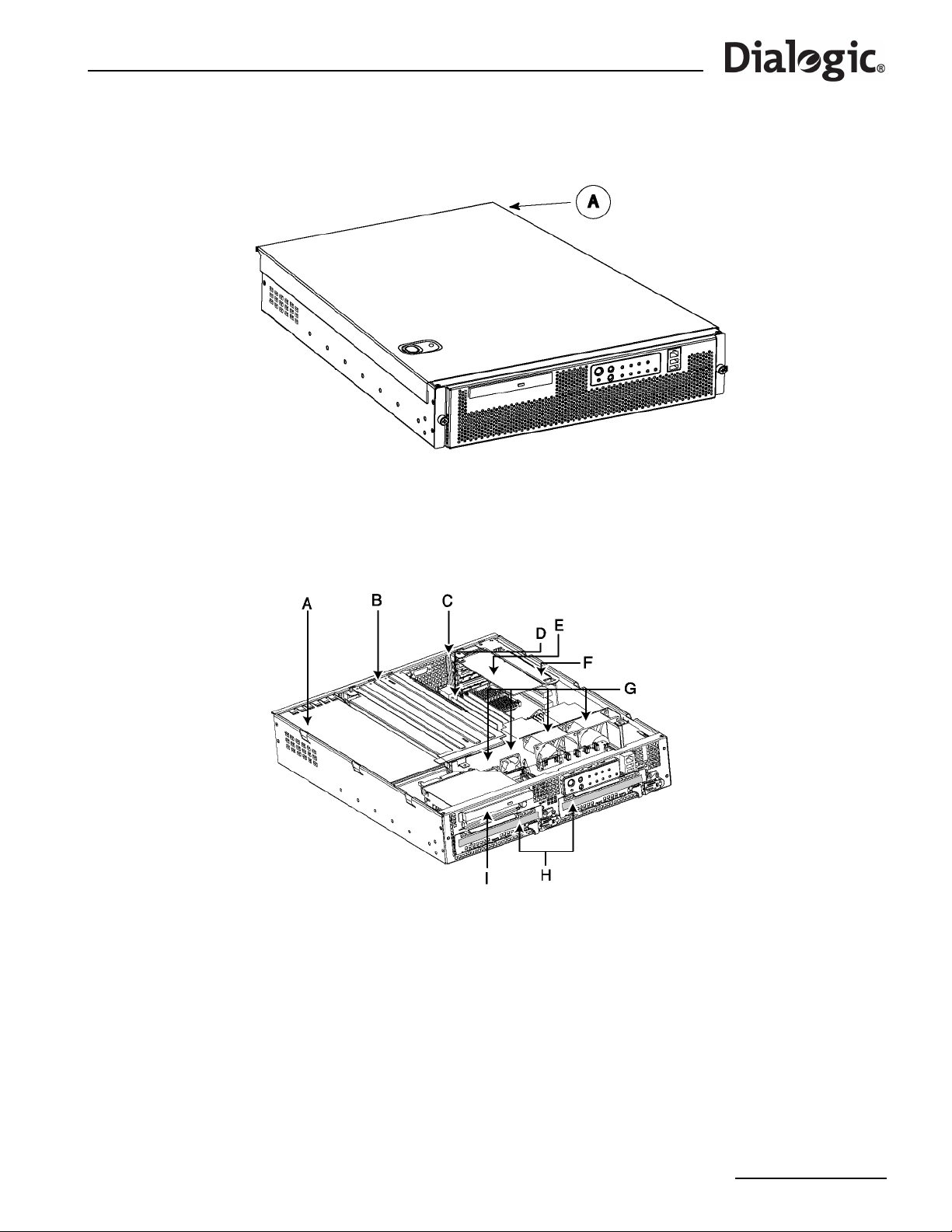
®
Dialogic
SS7G21 and SS7G22 Signaling Servers Hardware Manual Issue 7
Figure 19. Top Cover Removal and Installation
10.4 Internal Product Layout
The layout of the components in the chassis of the Dialogic
Figure 20, and the components are identified in Table 12.
®
SS7G21 or SS7G22 product is shown in
Figure 20. Internal Product Layout
61
Page 62

Chapter 10 Working Inside the Product
Table 12. Major Components in an SS7G21 and SS7G22 Chassis
Label in Figure 20 Component Name
A Power Supply Cage
B Signaling Board Subsystem
C PCI card bracket (low-profile)
DServer Board
E PCI NIC (low-profile)
F Riser Board assembly (low-profile)
G Chassis fans
H Hard Disk Drives (HDD) in carriers
I CD-ROM Drive
10.5 SS7 Signaling Boards
SS7G21 and SS7G22 are available with up to three SS7 Signaling Boards installed. The types of SS7
Signaling Boards that are installed depends on the model number.
The procedures in Section 10.5.1 to Section 10.5.3 describe the addition of new boards, and software
License Buttons, but the general description can be applied to the replacement of a failed board. See
Chapter 12, “Part Number Reference” for ordering information on standard product variants, SS7 Signaling
Boards and software License Buttons.
SS7G21 Variants
®
For the Dialogic
SS7G21 product, two possible types of SS7 Signaling Board can be use:
• SPCI2S boards have two E1/T1 PCM interface ports, and two V.11 (V.35 compatible) ports on a shared
connector. See Appendix A.
• SPCI4 boards have four E1/T1 PCM interface ports (and no V.11).
SS7G21 product variants with one, two, or three SPCI2S boards can be ordered by the suffix D1W, D2W or
D3W respectively , for example, SS 7G21AD1W. Product variants with one, two, or three SPCI4 boards can be
ordered by the suffix Q1W, Q2W or Q3W respectively, for example, SS7G21AQ1W.
In the case of the D1W, D2W, or Q1W, Q2W product variants, it is possible to add further SS7 Signaling
Boards, although each board purchased also requires a software License Button.
SS7G22 Variants
®
For the Dialogic
SS7G22 product, one type of board can be used:
• SS7HDP boards have four E1/T1 PCM interface ports (and no V.11).
SS7G22 product variants with zero, one, two, or three SS7HDP boards can be ordered by the suffix 00W,
H1W, H2W or H3W accordingly, for example, SS7G22AH1W.
In the case of 00W, H1W, H2W variants, it is possible to add further SS7 Signaling Boards, although each
board purchased also requires a software License Button.
10.5.1 Preparing SPCI Signaling Boards for Installation in SS7G21
The quantity, type, position and configuration of pre-installed SPCI Signaling Boards is determined by the
product variant suffix; D1W, D2W, D3W, Q1W, Q2W or Q3W, as shown in Table 13.
Use Table 13 to determine the position and configuration of any additional (or replacement) SPCI Signaling
Boards, and prepare the boards for installation. Ensure that the correct type of board is used. See
Section 10.5, “SS7 Signaling Boards” on page 62.
62
Page 63
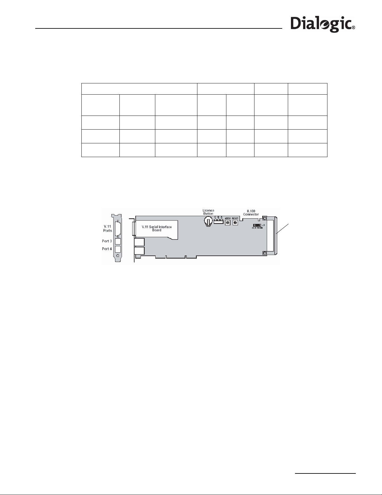
®
Dialogic
SS7G21 and SS7G22 Signaling Servers Hardware Manual Issue 7
Note: If only two SPCI Signaling Boards are installed, then the middle position (No.2) should remain
empty.
Table 13. Signaling Board Positions and Configurations for SS7G21 Product Variants
Quantity of Boards (Variant Suffix) Board Position ADDR Jumpers
1 board
(D1W /
Q1W)
Blank
Blank Blank
SPCI2S
or SPCI4
2 boards
(D2W /
Q2W)
SPCI2S
or SPCI4
SPCI2S
or SPCI4
3 boards
(D3W / Q3W)
SPCI2S
or SPCI4
SPCI2S
or SPCI4
SPCI2S
or SPCI4
Figure 21. SPCI2S and SPCI4 Board Layout
No. Position
3Top 2 Linked
2 Middle 1 Open (Offset)
1 Bottom 0 Linked
Switch
Setting
J3 CLK TERM
7 positions
ISA Edge
Retainer
Prepare an SPCI2S or SPCI4 Signaling Board for installation as follows:
1. Unscrew and discard the ISA edge retainer from new SPCI Signaling Boards (right end in Figure 21).
Record the board and License Button serial numbers on your product records, then fit the license button.
2. Set the ADDR switch on the SPCI Signaling Board as in Table 13. The BOOT switch shall be set to 0 for all
boards.
3. Ensure that 7 jumpers are fitted at J3 (CLK TERM). The jumpers are fitted in the “Linked” or “Open”
(offset) position according to Table 13.
Note: The ADDR switch setting number is used only for internal functionality of the product. The board
position number must be used for all configuration and wiring schedule purposes.
®
10.5.2 Preparing Dialogic
SS7HDP Signaling Boards for Installation in SS7G22
The type of signaling board must be the SS7HDP. The quantity, position and configuration, of pre-installed
SS7HDP Signaling Boards is determined by the product variant suffix; 00W, H1W, H2W or H3W, as shown in
Table 14.
Use Table 14 to determine the position and configuration of any additional (or replacement) SS7HDP
Signaling Boards, and prepare the boards for installation.
63
Page 64
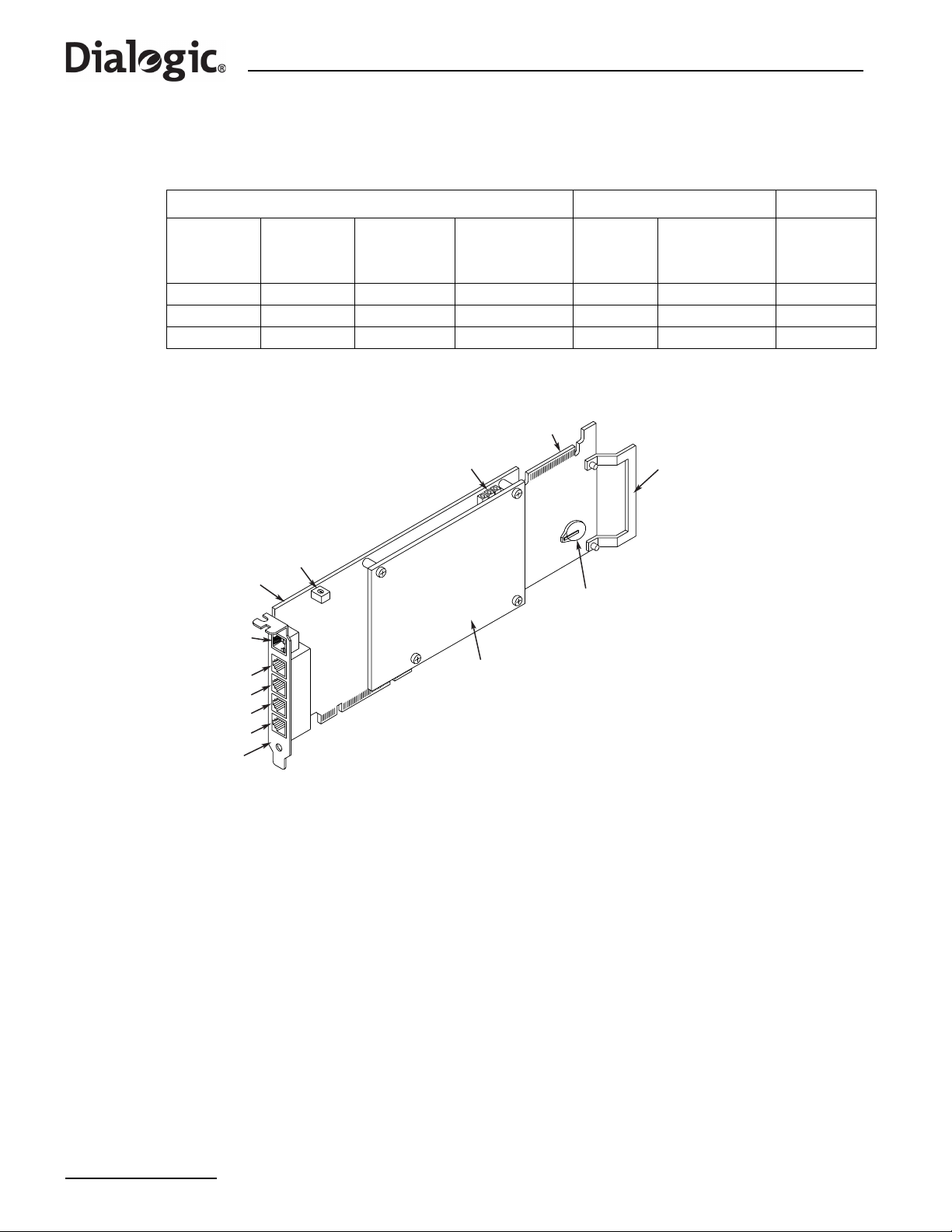
Chapter 10 Working Inside the Product
Note: If only two SS7HDP Signaling Boards are installed, then the middle position (No.2) should remain
empty.
®
Table 14. Signaling Board Positions and Configurations for Dialogic
Quantity of Boards (Variant Suffix) Board Position ADDR
SS7G22 Product Variants
0 boards
(00W)
Blank Blank SS7HDP SS7HDP 3 Top 2
Blank Blank Blank SS7HDP 2 Middle 1
Blank SS7HDP SS7HDP SS7HDP 1 Bottom 0
Figure 22. Dialogic
ENET
Port
Port L1
Port L2
Port L3
Port L4
End
Bracket
1 board
(H1W)
®
SS7HDP Board Layout
ADDR
Base
Board
2 boards
(H2W)
LEDs
Daughter
Board
3 boards
(H3W)
H.100 Edge
Connector
No. Position
ISA Edge
License
Button
Holder
Retainer
Switch
Setting
Prepare an SS7HDP Signaling Board for installation as follows:
1. Unscrew and discard the ISA edge retainer from a new SS7HDP Signaling Board (right end in Figure 22).
Record the board and software License Button serial numbers on your product records, then fit the
Licence Button.
2. Set the ADDR switch on the SS7HDP Signaling Board as in Table 14.
Note: The ADDR switch setting number is used only for internal functionality of the product. The board
position number must be used for all configuration and wiring schedule purposes.
10.5.3 Installing or Replacing an SS7 Signaling Board
Installation of extra SS7 Signaling Boards in positions No. 2 and No. 3, or replacement of a board in any
position, follow basically the same steps, but ensure that in each case the SS7 Signaling Board fitted is
correctly configured as identified in Table 13, “Signaling Board Positions and Configurations for SS7G21
Product Variants” on page 63 and Table 14, “Signaling Board Positions and Configurations for Dialogic
SS7G22 Product Variants” on page 64.
Install/Replace an SS7 Signaling Board as follows, referring to Figure 23:
1. Remove the Top Cover. See Section 10.3.
64
®
Page 65
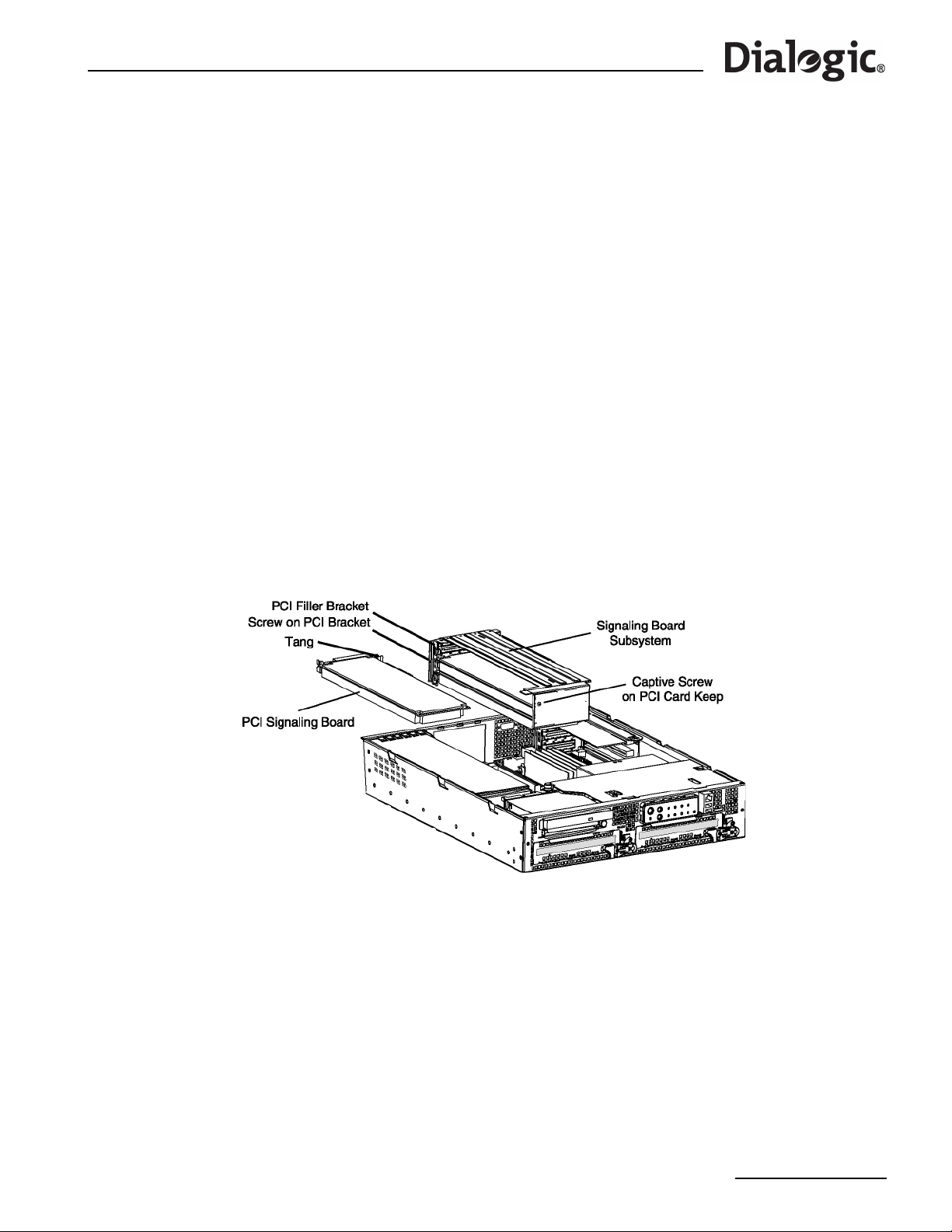
®
Dialogic
SS7G21 and SS7G22 Signaling Servers Hardware Manual Issue 7
2. To remove the Signaling Board Subsystem, un-latch it from the chassis by placing your thumb on the
rear chassis rail, and your fingers inside the recess at the rear of the Subsystem. A gentle squeeze will
then lift the rear part of the Subsystem and release the Riser Board from its connector. The Signalling
Board Subsystem can then be simply lifted upward out of the chassis.
3. Loosen the captive screw, and remove the PCI card keep.
4. If installing an extra SS7 Signaling Board, unscrew and remove the PCI filler bracket from the slot in
which the SS7 Signaling Board is to be inserted. Retain the screw.
5. If replacing an SS7 Signaling Board, cut the cable tie securing the board to the frame near the PCI card
keep location, as shown in Figure 24. Unplug the CT Bus cable connector from that board. Remove, but
retain, the screw on that PCI end bracket. The SS7 Signaling Board should then be unplugged from the
Riser Board, and be withdrawn from the frame.
6. Insert or replace the new SS7 Signaling Board, ensuring that the edge connector fully engages in the
Riser Board socket, and that the PCI end bracket tang (see Figure 23) locates in the loop on the frame.
Take great care to ensure that the EMC gasket (metal) fingers on the inside of the frame are not
damaged, and that the PCI end bracket of the SS7 Signaling Board is centrally aligned to make good
contact with them, and allow clear access for the network interface connectors.
7. Reinstall and tighten the screw on the PCI end bracket.
8. Reinstall the PCI card keep, and tighten the captive screw.
9. Connect the CT Bus cable to the SS7 Signaling Board. See CT Bus Cable Notes below.
10.Insert a new cable tie into the SS7 Signaling Board hole, tighten and crop, as shown in Figure 24.
11.Reinsert the Signaling Board Subsystem into the chassis, taking care to make sure that the interlocking
metal tabs on the back of the Signaling Board Subsystem are correctly inserted into the slots in the back
of the chassis, and that the Riser Board edge connector fully engages in the Server Board socket.
12.Install the Top Cover. See Section 10.3.
Figure 23. Installing and Replacing an SS7 Signaling Board
65
Page 66
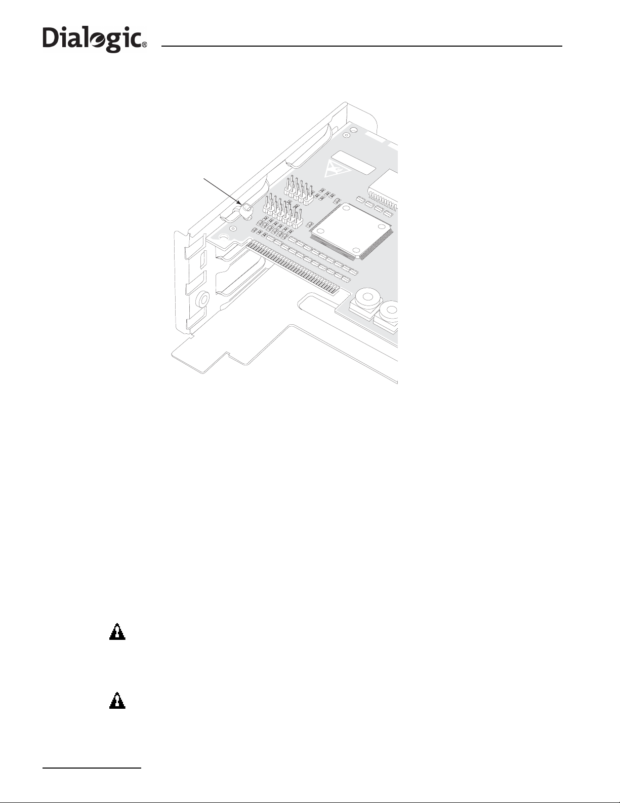
Chapter 10 Working Inside the Product
Figure 24. Cable Tie Securing SS7 Signaling Board to Card Keep Frame
Cable Tie
CT Bus Cable Notes
Note: When the CT Bus cable is installed, it is important that the two end connectors must be
connected to boards. To achieve this consider the following:
• For single board systems, the CT Bus cable cannot be connected. For systems delivered as “single
board”, the cable is stowed in clips fastened to the underside of the Top Cover.
• If adding a second board to a system, the CT Bus cable should be taken from the clips and connected to
the two boards.
• For “two board” systems, the two end connectors of the CT Bus cable must be used, and only the center
connector may be left disconnected.
10.6 Replacing the Back-up Battery
A lithium battery on the Server Board provides power to maintain date and time settings in the absence of
main AC or DC power. When the battery starts to weaken, it loses voltage, and the date and time settings
may be wrong. The battery may be replaced by one labeled with Manufacturer and Part Number information
that is identical to that marked on the original battery, or contact your customer service representative for
advice on approved equivalent devices.
WARNING
Danger of explosion if battery is incorrectly replaced. Replace only with the same or
equivalent type recommended by the equipment manufacturer. Discard used batteries
according to the manufacturer's instructions.
ADVARSEL!
66
Lithiumbatteri - Eksplosionsfare ved fejlagtig håndtering. Udskiftning må kun ske med
batteri af samme fabrikat og type. Levér det brugte batteri tilbage til leverandøren.
Page 67
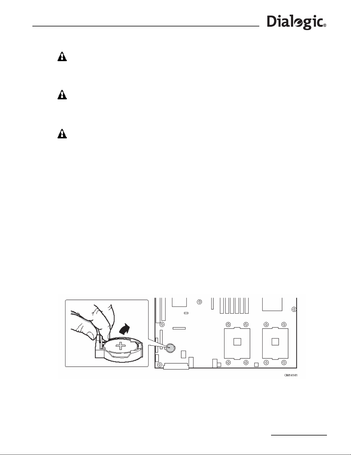
®
Dialogic
SS7G21 and SS7G22 Signaling Servers Hardware Manual Issue 7
ADVARSEL
Lithiumbatteri - Eksplosjonsfare. Ved utskifting benyttes kun batteri som anbefalt av
apparatfabrikanten. Brukt batteri returneres apparatleverandøren.
VARNING
Explosionsfara vid felaktigt batteribyte. Använd samma batterityp eller en ekvivalent
typ som rekommenderas av apparattillverkaren. Kassera använt batteri enligt
fabrikantens instruktion.
VAROITUS
Paristo voi räjähtää, jos se on virheellisesti asennettu. Vaihda paristo ainoastaan
laitevalmistajan suosittelemaan tyyppiin. Hävitä käytetty paristo valmistajan ohjeiden
mukaisesti.
To replace the back-up battery, follow this procedure:
1. Observe the Safety and ESD advice, warnings and cautions in Section 10.1 and Section 10.2.
2. Remove the T op Cov er as described in Section 10.3, and remove the Signaling Board Subsystem with the
SS7 Signaling Board(s) as described in Section 10.5.
3. Locate the battery on the Server Board (see Figure 25).
4. Push the upper end of the metal retainer away from the battery; the battery pops up.
5. Remove the battery from its socket.
6. Dispose of the old battery according to local ordinance.
7. Remove the new battery from its package.
8. Being careful to observe the correct polarity, lay the new battery in the socket.
9. Push the new battery down; the metal retainer locks the battery in the socket.
10.Replace the Signaling Board Subsystem and Top Cover as described in Section 10.5.3 and Section 10.3.
11.Restore the date and time settings by using the CNTDS command, as detailed in the appropriate SS7G2x
<Operating Mode> User Manual.
Figure 25. Replacing the Back-up Battery
67
Page 68

Chapter 10 Working Inside the Product
68
Page 69
®
Dialogic
SS7G21 and SS7G22 Signaling Servers Hardware Manual Issue 7
Chapter 11: International Warnings
11.1 WARNING: English
The power supply in this product contains no user-serviceable parts. There
may be more than one supply in this product. Refer servicing only to
qualified personnel.
Do not attempt to modify or use the supplied AC power cord if it is not the
exact type required. A product might be equipped with more than one AC
power cord.
The Power button on the system does not turn off all system power. To
remove all power from the system, you must unplug/disconnect the power
cord from the system.
To avoid injury from electrical and mechanical hazards, chassis covers
should only be removed by qualified service personnel.
SAFETY STEPS: Whenever you remove the chassis covers to acc ess the
inside of the system, follow these steps:
1. Turn off all peripheral devices connected to the system.
2. Turn off the system by pressing the Power button.
3. Unplug/disconnect the power cord from the system.
4. Label and disconnect all telecommunication cables and all other cables
connected to connectors or ports on the back of the system.
5. Provide some electrostatic discharge (ESD) protection by wearing an
anti-static wrist strap attached to chassis ground of the system—any
unpainted metal surface—when handling components.
6. Do not operate the system with the chassis covers removed.
After you have completed the five SAFETY steps above, you can remove
the system covers. To do this:
1. Remove and save all screws from the covers.
2. Remove the covers.
For proper cooling and airflow, always reinstall the chassis covers before
turning on the system. Operating the system without the covers in place
can damage system parts. To install the covers:
1. Check first to make sure you have not left loose tools or parts inside the
system.
2. Check that cables, add-in boards, and other components are properly
installed.
3. Atta ch the covers to the chassis with the screws removed earlier, and
tighten them firmly.
4. Connect all external cables and the power cord to the system.
continued
69
Page 70
Chapter 11 International Warnings
Warning: English (continued)
A microprocessor and heat sink might be hot if the system has been
running. Also, there might be sharp pins and edges on some board and
chassis parts. Contact should be made with care. Consider wearing
protective gloves.
Danger of explosion if the battery is incorrectly replaced. Re place only with
the same or equivalent type recommended by the equipment
manufacturer. Discard used batteries according to manufacturer’s
instructions.
The system is designed to operate in a typical office environment. Choose
a site that is:
• Clean and free of airborne particles (other than normal room dust).
• Well-ventilated and away from sources of heat including direct
sunlight.
• Away from sources of vibration or physical shock.
• I solated from strong electromagnetic fields produced by electrical
devices.
• Protected when in regions that are susceptible to electrical storms. W e
recommend you plug your system into a surge suppressor and
disconnect telecommunication lines to your modem during an electrical
storm.
• Provided with a properly grounded wall outlet.
• Provided with sufficient space to access the power supply cords,
because they serve as the product’s mains power disconnect.
Servers can be too heavy for a single person to lift or move safely.
Depending on the server, use two people or a mechanical assist to lift or
move the server.
70
Page 71
®
Dialogic
SS7G21 and SS7G22 Signaling Servers Hardware Manual Issue 7
11.2 AVERTISSEMENTS: Français
Le bloc d'alimentation de ce produit ne contient aucune pièce pouv a nt être
réparée par l'utilisateur. Ce produit peut contenir plusieurs blocs
d'alimentation. Veuillez contacter un technicien qualifié en cas de
problème.
Ne pas essayer d'utiliser ni de modifier le câble d'alimentation CA fourni,
s'il ne correspond pas exactement au type requis. Un produit peut être
équipé de plus d'un câble d'alimentation CA.
Le bouton d'alimentation du système n'éteint pas toutes les alimentations
CA du système. Pour mettre complètement le système hors tension, vous
devez débrancher chaque cordon d'alimentation CA de sa prise.
Pour éviter toute lé sion à la s uite de ris ques él ectriques et mécaniqu es, les
panneaux du châssis ne doivent être démontés que par un personnel
qualifié.
CONSIGNES DE SÉCURITÉ : Lorsque vous retirez les panneaux du
châssis pour accéder à l'intérieur du système, suivez les étapes cidessous:
1. Mettez hors ten sion tous les périphériques connectés au système.
2. Mettez hors tension le système en appuyant sur le bouton
d'alimentation.
3. Débranchez tous les cordons d'alimen tation CA du système ou des
prises murales.
4. Identifiez et déconnectez tous les câbles de télécommunications et tous
les autres câbles reliés aux connecteurs E/S ou aux ports derrière le
système.
5. Pour prévenir les décharges électrostatiques lorsque vous touchez aux
composants, portez une bande antistatique pour poignet et reliez-la à la
masse du système (toute surface métallique non peinte du boîtier).
6. Ne faites pas fonctionner le système si les panneaux du châssis sont
enlevés.
Après avoir suivi les six consignes de SECURITE ci-dessus, vous pouvez
retirer les panneaux du système. Pour effectuer cette opération:
1. Retirez et conservez toutes les vis des panneaux.
2. Retirez les panneaux.
suite
71
Page 72
Chapter 11 International Warnings
Avertissements : Français (suite)
Afin de permettre le refroidissement et l'aération du système, réinstallez
toujours les panneaux du châssis avant de mettre le système sous tension.
Le fonctionnement du système en l'absence des panneaux risque
d'endommager ses pièces. Pour installer les panneaux, procédez comme
suit:
1. Assurez-vous ne pas avoir oublié d'outils ou de pièces démontées dans
2. Assurez-vous que les câbles, les cartes d'extension et les autres
3. Revissez solidement l es panneaux du châssis avec les vis retirées plus
4. Rebranchez tous les cordons d'alimentation CA et câbles externes au
Le microprocesseur et le dissipateur de chaleur peuvent être chauds si le
système a été sous tension. Faites également attention aux broches aiguës
des cartes et aux bords tranchants du capot. Les contacts doivent être
établis avec soin. L'usage de gants de protection est conseillé.
le système.
composants sont bien installés.
tôt.
système.
Danger d'explosion si la batterie n'est pas remontée correctement.
Remplacer uniquement par une pile du même type ou de type équivalent
recommandé par le fabricant. Débarrassez-vous des piles usagées
conformément aux instructions du fabricant.
Le système a été conçu pour fonctionner dans un cadre de travail normal.
L'emplacement choisi doit être:
• Propre et dépourvu de poussières en suspension (sauf la poussière
normale).
• Bien aéré et loin des sources de chaleur, y compris du soleil direct.
• À l'abri des chocs et des sources de vibration.
• Isolé des forts champs électromagnétiques générés par des appareils
électriques.
• Protégé s'il se trouve dans des régions sujettes aux orages
magnétiques. Nous vous recommandons de connecter votre système à
un suppresseur de surtension et de déconnecter les lignes de
télécommunications de votre modem pendant un orage magnétique.
• Muni d'une prise murale correctement mise à la terre.
• Suffisamment spacieux pour vous permettre d'accéder aux câbles
d'alimentation (ceux-ci étant le seul moyen de mettre le système hors
tension).
Il se peut que les serveurs soient trop lourds pour qu'une seule personne
puisse les soulever et les déplacer en toute sécurité. En fonction du
serveur, utilisez deux person nes ou utilisez un équipement mécanique
auxiliaire pour soulever ou déplacer le serveur.
72
Page 73
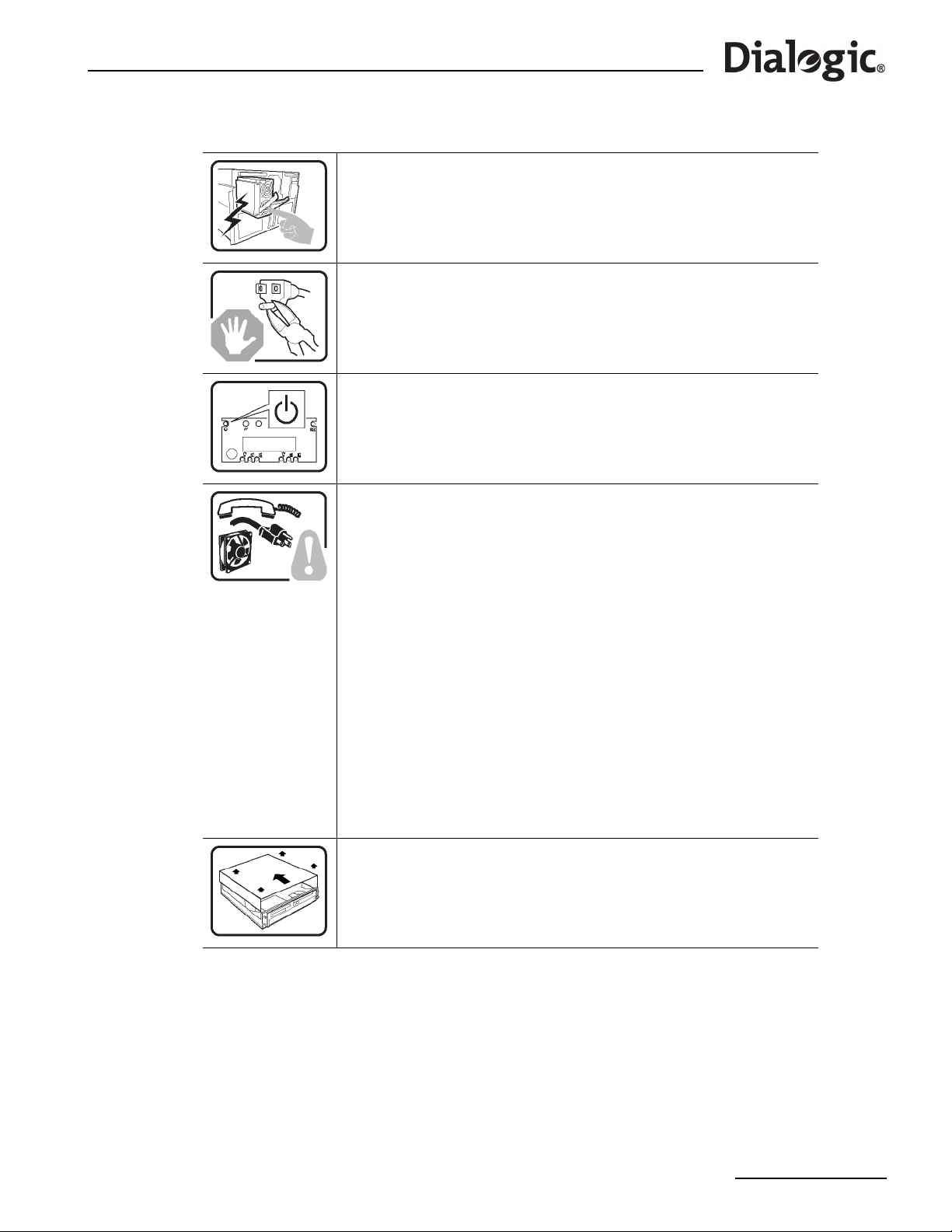
®
Dialogic
SS7G21 and SS7G22 Signaling Servers Hardware Manual Issue 7
11.3 WARNUNG: Deutsch
Das Netzteil dieses Computers enthält keine wartungsbedürftigen Teile.
Dieses Produkt kann über mehrere Netzteile verfügen. Überlassen Sie
Wartungsarbeiten nur qualifizierten Fachleuten.
Versuchen Sie nicht, das mitgelieferte Netzkabel zu verändern oder
einzusetzen, wenn es nicht exakt dem benötigten Kabeltyp entspricht. Das
Produkt kann über mehrere Netzkabel verfügen.
Durch Ausschalten des Netzschalters wird die Wechselstromversorgung
des Systems
nicht unterbrochen. Um das System vom Netz zu trennen, müssen Sie das
Netzkabel
aus der Steckdose oder vom Netzteil abziehen.
Vermeiden Sie Verletzungen aufgrund elektrischer oder mechanischer
Gefahren; lassen Sie daher den Gehäusedeckel nur von technisch
qualifiziertem Personal abnehmen.
SICHERHEITSHINWEISE: Beachten Sie beim Abnehmen der
Gehäuseabdeckung und Arbeiten im Inneren des Systems folgende
Schritte:
1. Schalten Sie alle am System angeschlossenen Peripheriegeräte ab.
2. Drücken Sie den Netzschalter, um das System abzuschalten.
3. Ziehen Si e alle Wechselstromkabel vom System und den Steckdosen
ab.
4. Kennzeichnen Sie alle Telekommunikationsleitungen und sonstigen
Kabel an den
E/A-Steckern bzw. Anschlüssen an der Rückseite des Systems, und
trennen Sie
diese vom Netz.
5. Um si ch gegen elektrostatische Entladung zu schützen, sol lten Sie eine
Antistatik-Manschette tragen, die Sie beim Arbeiten mit Komponenten
zur Erdung an einem beliebigen unlackierten Metallteil befestigen.
6. Nehmen Sie das System nicht ohne Abdeckung in Betrieb.
Nachdem Sie die fünf Sicherheitshinweise oben beachtet haben , können
Sie die Gehäuseabdeckung abnehmen. Gehen Sie wie folgt vor:
1. Entfernen Sie sämtliche Schrauben der Gehäuseabdeckung, und
bewahren Sie diese auf.
2. Nehmen Sie die Gehäuseabdeckung ab.
Fortsetzung
73
Page 74
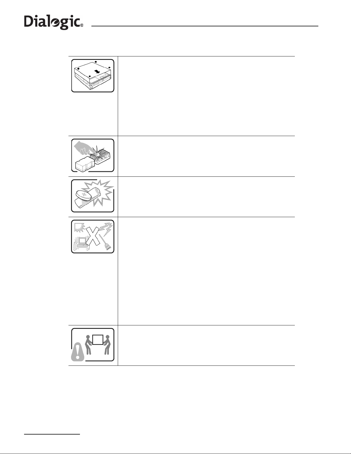
Chapter 11 International Warnings
Warnung: Deutsch (Fortsetzung)
Um eine ordnungsgemäße Kühlung und Belüftung zu gewährleisten,
sollten Sie stets die Gehäuseabdeckung anbringen, bevor Sie das System
in Betrieb nehmen. Wenn das System ohne obere und vordere Abdeckung
betrieben wird, kann es zu einer Beschädigung der Systemkomponenten
kommen. So entfernen Sie die Gehäuseabdeckung:
1. Prüfen Sie, daß weder Werkzeuge noch Kleinteile im Innern des
Systems vergessen wurden.
2. Prüfen Sie, ob die Kabel und anderen Komponenten richtig installiert
sind.
3. Schrauben Sie die Abdeckung mit den zuvor gelösten Schrauben gut
am Gehäuse fest.
4. Schließen Sie alle externen Kabel und das Netzkabel an das System an.
Mikroprozessor und Kühlkörper können heiß sein, wenn das System
längere Zeit eingeschaltet war. Einige Platinen- und Gehäuseteile können
scharfe Spitzen und Kanten aufweisen. Gehen Sie auf jeden Fall mit
Vorsicht heran. Das Tragen von Schutzhandschuhen wird em pfohlen.
Wird die Batterie unsachgemäß ausgewechselt, besteh t Explosionsgefahr.
Ersetzen Sie die Batterie nur durch denselben oder einen gleichwertigen
Batterietyp, der vom Gerätehersteller empfohlen wird. Entsorgen Sie
verbrauchte Batterien gemäß den Herstellerempfehlungen.
Das System ist für den Betrieb innerhalb normaler Büroumgebungen
geeignet. Der Standort sollte folgende Anforderungen erfüllen:
• Saubere, möglichst staubfreie Umgebung.
• Gut belüftet und weit entfernt von Wärmequellen wie direkte
Sonneneinstrahlung.
• V ibrations- und erschütterungsfreie Umgebung.
• Abgeschirmt von starken elektromagnetischen Feldern, die durch
elektrische Geräte erzeugt werden.
• Entsprechender Schutz bei Betrieb in gewittergefährdeten Gebieten. Es
empfiehlt sich, den Computer über einen Überspannungsschutz
anzuschließen und die Verbindung zwischen dem Modem und dem
Telefonanschluß im Falle eines Gewitters zu trennen.
• Ausgestattet mit einer ordnungsgemäß geerdeten Wandsteckdose.
• S orgen Sie für ausreichend Platz, damit das Servernetzkabel
problemlos erreicht werden kann, da das Gerät nur über dieses Kabel
vom Netz
getrennt wird.
Um einen Server sicher anzuheben und zu bewegen ist eine Person nicht
ausreichend. Bewegen Sie den Server, je nach Größe, entweder zu zweit
oder mittels einer mechanischen Hilfe.
74
Page 75
®
Dialogic
SS7G21 and SS7G22 Signaling Servers Hardware Manual Issue 7
11.4 AVVERTENZA: Italiano
L'alimentatore contenuto nel computer non contiene parti riparabili
dall'utente. Questo prodotto può essere fornito con più alimentatori. Per
l'assistenza fare riferimento solo a personale qualificato.
Non tentare di modificare o utilizzare cavi di alimentazione in c.a. che non
siano del tipo prescritto. Un prodotto potrebbe contenere più di un cavo di
alimentazione in c.a.
L'interruttore di accensione del sistema non scollega tutta l'alimentazione
in c.a. del sistema. Per scoll egare tutta l'alimentazione in c.a., è necessario
disinserire ogni cavo di alimentazione in c.a. dalla presa a muro o
dall'alimentatore.
Per evitare incidenti elettrici e meccanici, i coperchi del telaio devono
essere rimossi da personale qualificato.
MISURE DI SICUREZZA: Nel caso sia necessario rimuovere i coperchi del
telaio per accedere alle parti interne del sistema, procedere nel seguente
modo:
1. Spegnere tutte le periferiche collegate al sistema.
2. Spegnere il sistema premendo il pulsante di accensione.
3. Scollegare tutti i cavi di alimentazione in c.a. dal sistema o dalle prese a
muro.
4. Apporre un'etichetta e scollegare tutti i cavi di telecomunicazione e i
cavi collegati ai connettori di I/O o alle porte sulla parte posteriore del
sistema.
5. Assicurare un minimo di protezione da scariche elettrostatiche (ESD)
indossando un bracciale antistatico collegato a un componente metallico
non verniciato del telaio quando si maneggiano i componenti.
6. Non attivare il sistema nel caso in cui i coperch i del telaio siano stati
rimossi.
Dopo aver effettuato le operazioni di SICUREZZA descritte in precedenza, è
possibile rimuovere i coperchi del sistema. Procedere nel modo seguente:
1. Rimuovere e conservare tutte le viti dei coperchi.
2. Rimuovere i coperchi.
continua
75
Page 76
Chapter 11 International Warnings
Avvertenza: Italiano (continua)
Per evitare che il sistema si surriscaldi e per garantire una
ventilazione adeguata, reinstallare sempre i coperchi prima di attivar e
il sistema. Se si attiva il sistema senza aver riposizionato i coperchi
correttamente, alcune parti del sistema potrebbero risultare
danneggiate. Per installare i coperchi:
1. Verificare innanzitutto di non aver lasciato utensili o altre parti
all'interno del sistema.
2. Verificare che i cavi, le schede aggiuntive e gli altri componenti
siano stati installati correttamente.
3. Fissare saldamente i coperchi al telaio utilizzando le viti
precedentemente rimosse.
4. Collegare tutti i cavi esterni e il cavo o i cavi di alimentazione in
c.a. al sistema.
Se il sistema è stato in funzione, il microprocessore e il dissipatore di
calore potrebbero essere caldi. Inoltre su alcune parti della scheda e
del telaio potrebbero esserci piedini appuntiti e bordi taglienti.
Prestare quindi molta attenzione nel toccarli. Indossare guanti
protettivi.
Se sostituita in modo errato, la batteria potrebbe esplodere.
Sostituire le batterie scariche solo con batterie originali o del tipo
consigliato dal produttore dell'apparecchiatura. Per lo smaltimento
delle batterie usate attenersi alle istruzioni del produttore.
Il sistema è concepito per l'utilizzo in ambienti adibiti a ufficio.
Scegliere una postazione con le caratteristiche riportate di seguito.
• Pulita, priva di particelle diverse dalla polvere normalmente
presente nell'ambiente di lavoro.
• Aerata e lontana da fonti di calore, compresa la luce solare
diretta.
• Lontana da fonti di vibrazione o urti.
• Isolata da forti campi elettromagnetici prodotti da apparecchi
elettrici.
• Protetta nelle regioni soggette a temporali. Durante un temporale,
si consiglia di collegare il sistema a un limitatore di corrente e di
scollegare le linee di telecomunicazione dal modem.
• La posizione prescelta deve essere dotata di una presa a muro
con adeguata messa a terra.
• Deve inoltre esserci sufficiente spazio per accedere ai cavi di
alimentazione nel caso sia necessario scollegare l'alimentazione
principale.
I server possono risultare troppo pesanti per essere sollevati o
spostati da una sola persona. Alcuni server devono dunque essere
sollevati o spostati da due persone o da un assistente tecnico.
76
Page 77
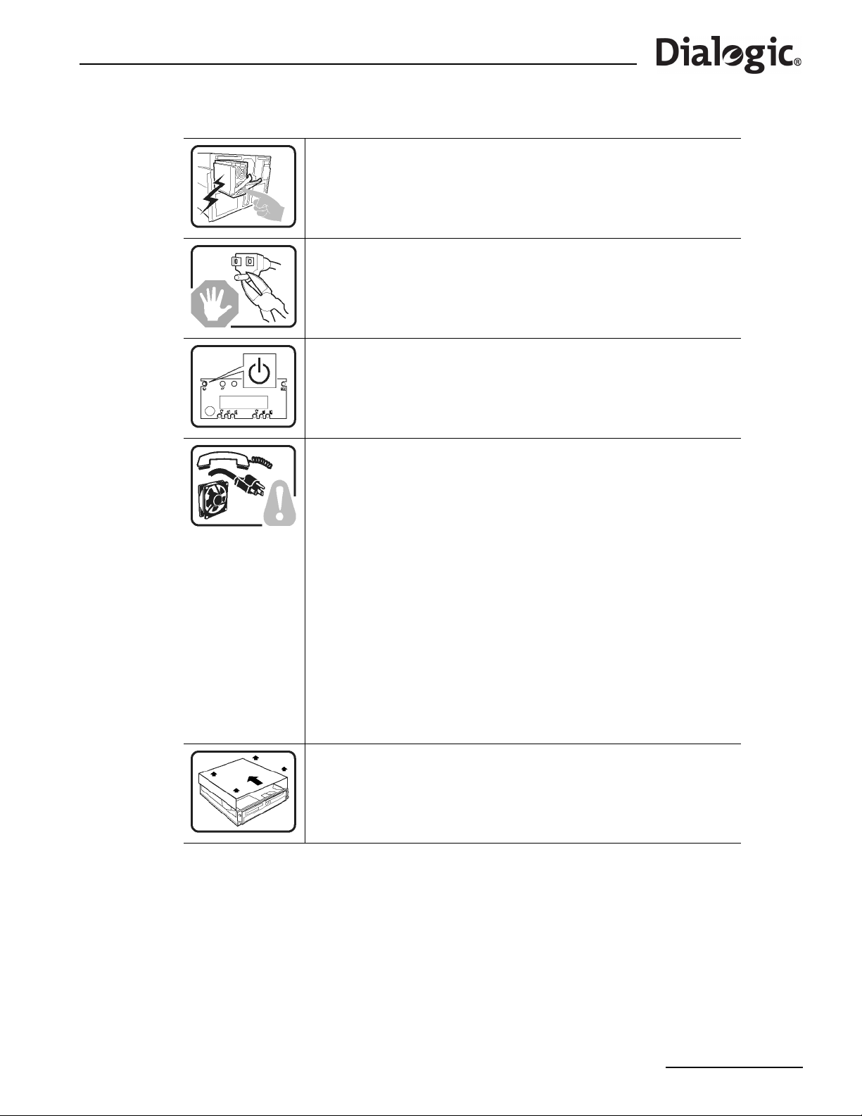
®
Dialogic
SS7G21 and SS7G22 Signaling Servers Hardware Manual Issue 7
11.5 ADVERTENCIA: Español
La fuente de alimentación de este producto no contiene piezas que puedan
ser reparadas por el usuario. Puede que haya más de una fuente de
alimentación en este producto. Para las reparaciones, consulte sólo con el
personal cualificado.
No intente modifica ni utilizar el cable de alimentación de CA su mi nistrado
si no es del tipo exacto requerido. Un producto puede estar equipado con
más de un cable de alimentación de CA.
El botón de alimentación del sistema no desactiva toda la alimentación de
CA del sistema. Para eliminar toda la alimentación de CA del sistema,
deberá desenchufar todos los cables de alimentación de CA del enchufe de
pared o de la fuente de alimentación.
Para evitar lesiones causadas por descargas eléctricas y mecánicas,
únicamente puede retirar las cubiertas de las carcasas el personal técnico
cualificado.
PASOS DE SEGURIDAD: Siempre que retire las cubiertas de las carcasas
para acceder al interior del sistema, siga las instrucciones que se
especifican a continuación:
1. Desactive todos los dispositivos periféricos conectados al sistema.
2. Pulse el botón de alimentación para desactivar el sistema.
3. Desenchufe todos los cables de alimentación de CA del sistema o de los
enchufes de pared.
4. Etiquete y desconecte todas las líneas de telecomunicaciones y todos
los cables conectados a los puertos o conectores de E/S de la parte
posterior del sistema.
5. Para contar con cierto grado de protección contra descargas
electrostáticas (ESD), utilice un brazalete antiestático conectado a la
toma de tierra del sistema (cualquier superficie de metal que no esté
pintada) al manipular sus componentes.
6. No utilice el sistema sin las cubiertas de la carcasa.
Una vez que haya completado los cinco pasos de SEGURIDAD, podrá
retirar las cubiertas del sistema. Para ello:
1. Retire y guarde todos los tornillos de las cubiertas.
2. Retire las cubie rtas.
continuación
77
Page 78
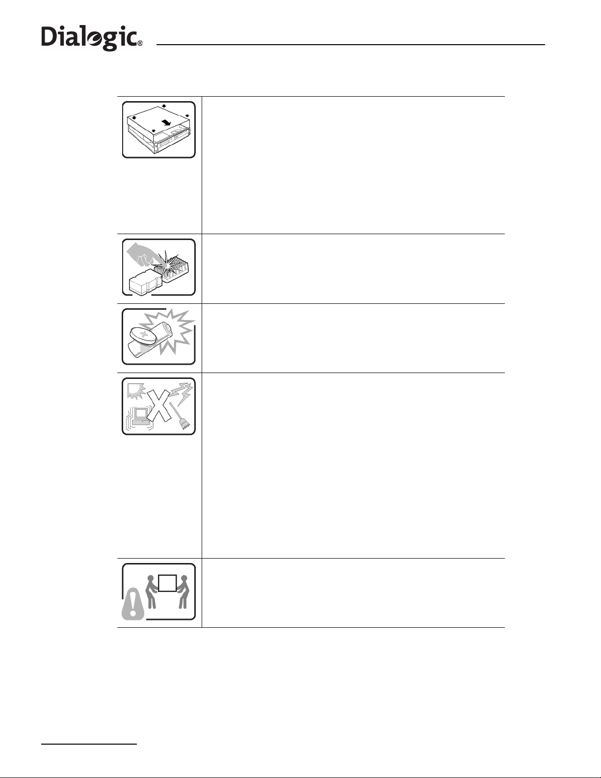
Chapter 11 International Warnings
Advertencia: Español (continuación)
Para obtener una ventilación y un flujo de aire adecuados, reinstale
siempre las cubiertas de la carcasa antes de encender el sistema. Si utiliza
el sistema sin las cubiertas en su lugar , puede que se dañen algunas piezas
del sistema. Para instalar las cubiertas:
1. Asegúrese primero de no haber dejado piezas o herramientas sueltas
en el sistema.
2. Compruebe que los cables, tarjetas adicionales y demás componentes
están correctamente instalados.
3. Fije las cubi ertas a la carcasa con los tornillos que ha retirado
anteriormente y apriételos firmemente.
4. Conecte todos los cables externos y los cables de alimentación de CA al
sistema.
Puede que el microprocesador y el disipador de calor se recalienten si se
ha estado ejecutando el sistema. Asimismo, puede que algunas tarjetas o
piezas de la carcasa tengan patillas o bordes afilados. Los contactos
deberán realizarse cuidadosamente. Puede que sea conveniente llevar
guantes de protección.
Existe peligro de explosión si la batería se sustituye incorrectamente.
Sustitúyala sólo por el mismo tipo o uno equivalente recomendado por el
fabricante del equipo. Deseche las baterías usadas según las instrucciones
del fabricante.
El sistema está diseñado para que funcione en un entorno de oficina típico.
Elija un emplazamiento:
• Limpio y libre de partículas de transportadas por aire (aparte del polvo
normal de la habitación).
• Bien ventilado y alejado de las fuentes de calor, incluida la luz del sol
directa.
• Alejado de las fuentes de vibración o de los golpes físicos.
• Aislado de campos electromagnéticos fuertes producidos por
dispositivos eléctricos.
• Protegido, si se encuentra en regiones susceptibles de tormentas
eléctricas. Se recomienda que enchufe el sistema a un supresor de
sobretensiones y desconecte las líneas de telecomunicaciones al
módem durante una tormenta eléctrica.
• Que tenga un enchufe de pared correctamente conectado a tierra.
• Con suficiente espacio para acceder a los cables de la fuente de
alimentación, ya que éstos sirven como desconectador de alimentación
principal del sistema.
Los servidores pueden ser demasiado pesados para que una sola persona
los levante o los mueva de forma segura.
Dependiendo del servido, utilice dos per sonas o una ayuda mecánica para
levantar o mover el servidor.
78
Page 79
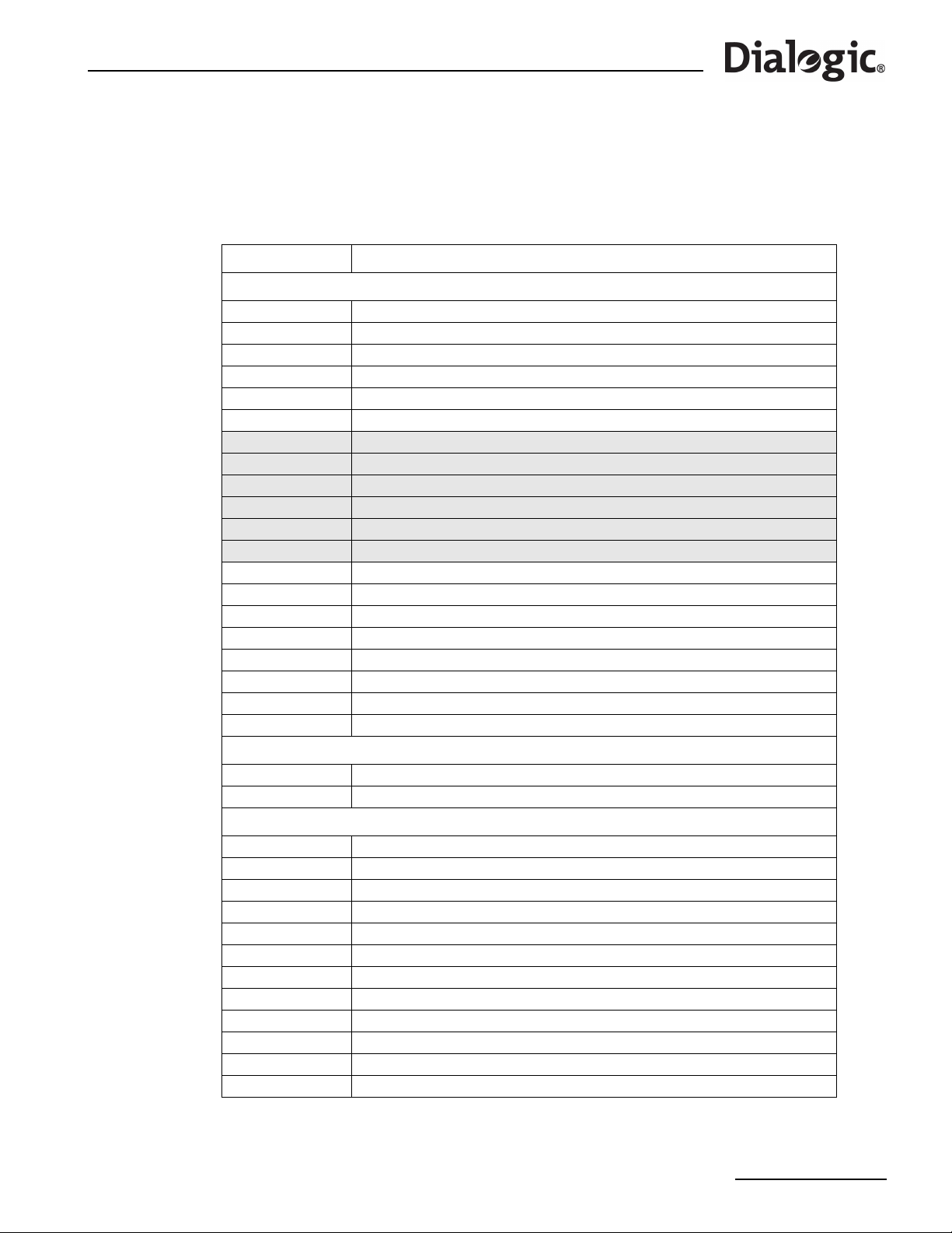
®
Dialogic
SS7G21 and SS7G22 Signaling Servers Hardware Manual Issue 7
Chapter 12: Part Number Reference
Table 15 shows the Dialogic® SS7G2x product IDs, operating mode IDs and the supported protocol module
IDs. Table 16 gives the product IDs of the expansion options or spare assemblies available for SS7G2x
products and Table 17 gives the product IDs of the accessories that can be used with SS7G2x products.
Table 15. SS7G21, SS7G22 Product IDs and SS7G20 Modes and Protocol Module IDs
Product ID Description
SS7G21 and SS7G22 Product IDs
SS7G21AQ1W SS7G21 unit, AC powered, 4 SS7 links, 4 T1/E1 ports
SS7G21AQ2W SS7G21 unit, AC powered, 8 SS7 links, 8 T1/E1 ports
SS7G21AQ3W SS7G21 unit, AC powered, 12 SS7 links, 12 T1/E1 ports
SS7G21DQ1W SS7G21 unit, DC powered, 4 SS7 links, 4 T1/E1 ports
SS7G21DQ2W SS7G21 unit, DC powered, 8 SS7 links, 8 T1/E1 ports
SS7G21DQ3W SS7G21 unit, DC powered, 12 SS7 links, 12 T1/E1 ports
SS7G21AD1W SS7G21 unit, AC powered, 4 SS7 links, 2 T1/E1 ports, 2 V.11 ports
SS7G21AD2W SS7G21 unit, AC powered, 8 SS7 links, 4 T1/E1 ports, 4 V.11 ports
SS7G21AD3W SS7G21 unit, AC powered, 12 SS7 links, 6 T1/E1 ports, 6 V.11 ports
SS7G21DD1W SS7G21 unit, DC powered, 4 SS7 links, 2 T1/E1 ports, 2 V.11 ports
SS7G21DD2W SS7G21 unit, DC powered, 8 SS7 links, 4 T1/E1 ports, 4 V.11 ports
SS7G21DD3W SS7G21 unit, DC powered, 12 SS7 links, 6 T1/E1 ports, 6 V.11 ports
SS7G22A00W SS7G22 unit, AC powered, 0 SS7 Links, 0 T1/E1 ports
SS7G22AH1W SS7G22 unit, AC powered, 64 SS7 links, 4 T1/E1 ports
SS7G22AH2W SS7G22 unit, AC powered, 128 SS7 links, 8 T1/E1 ports
SS7G22AH3W SS7G22 unit, AC powered, 128 SS7 links, 12 T1/E1 ports
SS7G22D00W SS7G22 unit, DC powered, 0 SS7 Links, 0 T1/E1 ports
SS7G22DH1W SS7G22 unit, DC powered, 64 SS7 links, 4 T1/E1 ports
SS7G22DH2W SS7G22 unit, DC powered, 128 SS7 links, 8 T1/E1 ports
SS7G22DH3W SS7G22 unit, DC powered, 128 SS7 links, 12 T1/E1 ports
Operating Mode IDs
SS7SBG20DSC SS7G20 DSC mode software license
SS7SBG20SGW SS7G20 SGW mode software license
Protocol Module IDs
SS7SBG20BICC SS7G20 BICC protocol software licence
SS7SBG20INAP SS7G20 INAP protocol software license
SS7SBG20IS41 SS7G20 IS41 protocol software license
SS7SBG20ISUP SS7G20 ISUP protocol software license
SS7SBG20M2PA SS7G20 M2PA protocol software license
SS7SBG20M3UAL SS7G20 M3UA large protocol software licence
SS7SBG20M3UAR SS7G20 M3UA regular protocol software licence
SS7SBG20M3UAS SS7G20 M3UA small protocol software licence
SS7SBG20MAP SS7G20 MAP protocol software license
SS7SBG20SCCPCL SS7G20 SCCP CL protocol software license
SS7SBG20SCCPCO SS7G20 SCCP CO protocol software license
SS7SBG20TCAP SS7G20 TCAP protocol software license
79
Page 80
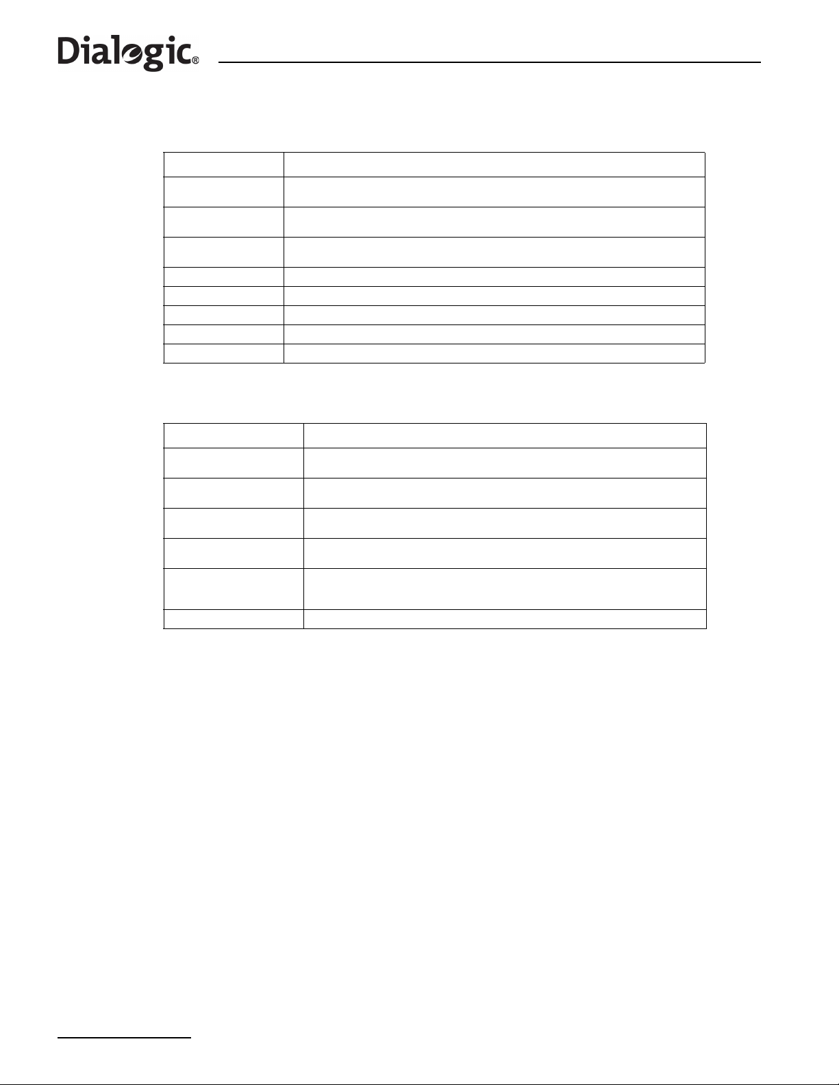
Chapter 12 Part Number Reference
Table 16. Expansion Options or Spare Assemblies
Product ID Description
SS7SPCI2SQ
SS7SPCI4Q
SS7HDPD4TEW
SS7SBPCISYSQ License Button (Install in SS7SPCI2SQ and SS7SPCI4Q Signaling Boards above)
SS7SBHDFBGQ License Button (Install in the SS7HDPD4TEW Signaling Board above)
SS7G20SACPSU AC Power Supply Module [TLPACPSU002]
SS7G20SDCPSU DC Power Supply Module [TLPDCPSU002]
SS7G20SHDD Spare Hard Drive with software for SS7G2x
SS7 Signaling Board, 4 SS7 links, 2 E1/T1, 2 V.11 ports
(use in conjunction with License Button)
SS7 Signaling Board, 4 SS7 links, 4 E1/T1 ports
(use in conjunction with a License Button)
SS7 Signaling Board, 64 SS7 links, 4 E1/T1 ports
(use in conjunction with a License Button)
Table 17. Accessories
Product ID Description
SS7G20R19LBR
SS7G20R19MNT
SS7G20R23MNT
SS7G20RSLKIT
SS7DKL26
CBLCTB3DROPQ Ribbon Cable, H.100, 3 drop - Joins H.100 connectors of SS7 Signaling Boards
2-post 19” rack mount ‘L’ bracket kit. See Section 5.4, “Rack Mounting Options”
on page 34 for more information. [TMLCMOUNT21]
2/4-post 19" rack mount, See Section 5.4, “Rack Mounting Options” on page 34
for more information. [TMLPMOUNT51]
2/4-post 23" rack mount. See Section 5.4, “Rack Mounting Options” on page 34
for more information. [TMLPMOUNT52]
Enabling kit for use with slide rails. See Section 5.4, “Rac k Mounting Opti ons” on
page 34 for more information. [TMLPSLIDE01]
Splitter Cable Assembly, SS7 Serial Interface Port, 2 metres long,
(26-way dual V.11) splits to 2 x (DB15 - V .11). See Table 7, “SS7 Serial Interface
Port Splitter Cable 15-Way Male DB15 Connector Pinouts” on page 38.
80
Page 81

®
Dialogic
SS7G21 and SS7G22 Signaling Servers Hardware Manual Issue 7
Chapter 13: Software Licensing Information
This chapter gives important information relating to licensed software used by these products.
13.1 Linux Software Distribution
This product uses a Linux software distribution. The distribution and full source code can be downloaded
from:
ftp://archive.download.redhat.com/pub/redhat/linux/9/en/iso/i386
In addition, the
#!/bin/sh
#
# This script will be executed *after* all the other init scripts.
# You can put your own initialization stuff in here if you don't
# want to do the full Sys V style init stuff.
touch /var/lock/subsys/local
# Additional
if test -r /root/firstboot
then
/root/firstboot
rm /root/firstboot
shutdown -r now
fi
#
sysctl -w kernel/msgmni=128
sysctl -w kernel/msgmnb=65536
if test -r /etc/rc.d/rc.new
then
echo Updating rc.dkl
rm -f /etc/rc.d/rc.dkl
mv /etc/rc.d/rc.new /etc/rc.d/rc.dkl
chmod +x /etc/rc.d/rc.dkl
fi
/etc/rc.d/rc.dkl &
rc.local file has been modified and is shown below.
13.2 GNU 'C' Library
This product uses the GNU 'C' Library as distributed in the software distribution mentioned in Section 13.1
above. The GNU 'C' Library is licensed subject to the GNU Lesser General Public License (LGPL) Version 2.1,
February 1999, available at:
http://www.fsf.org/licenses/lgpl.html
Full source code for the library can be downloaded from:
ftp://archive.download.redhat.com/pub/redhat/linux/9/en/iso/i386
81
Page 82

Chapter 13 Software Licensing Information
82
Page 83

®
Dialogic
SS7G21 and SS7G22 Signaling Servers Hardware Manual Issue 7
Appendix A
A.1 Connecting to V.11 (V.35-Compatible) SS7 Links
This appendix discusses the issues of connecting SS7G21 product variants which include SPCI2S boards to a
V.35 interface. See the Chapter 12, “Part Number Reference” for the complete list of products variants. Units
designated SS7G21ADxW and SS7G21DDxW have SPCI2S boards pre-installed.
The V.35 interface was originally specified by CCITT as an interface for 48 kbps line transmissions, and was
discontinued by the CCITT (now ITU-T) in 1988, whe n it was replaced by recommendations V.10 and V.11.
V.35 has been adopted as a standard interface to carry SS7 to an STP in North America. The interface is little
used in Europe and Asia.
V.35 is a mixture of balanced (RS-422 like) and common earth (RS-232 like) signal interfaces. The control
lines including DTR, DSR, DCD, RTS and CTS are single wire common earth interfaces, functionally
compatible with RS-232 level signals. The data and clock signals are balanced,
RS-422 like signals.
There appears to be many different styles of connectors used in SS7 networks for connection to V.35
interfaces; the most common being an M34 “block connector”.
A.1.1 Connectors on the SPCI2S Signaling Board
The SPCI2S provides two V.11 interfaces, designated as port A and port B. Both interfaces are physically
sited on the same connector, that is, a high-density, 26-way D-type (DB) female connector, essentially 26
pins in a standard 15-way back shell. See Section 6.5, “SS7 Serial Interface Ports” on page 36 for more
information.
The V.11 ports on the SPCI2S support clock and data signals only, they do not support any control lines. On
the practical side, this does sometimes mean that it is necessary to loopback one or more control lines to the
remote end of the interconnecting cable, or in some circumstances be disabled at the remote equipment. It
should not be significant in the operation of the SS7 protocol, since SS7 has very good built-in error
detection that quickly detects any break in the signaling path (for whatever reason).
A.1.2 Cabling
Since it may be difficult to obtain a high-density, 26-way, D-type connector, Dialogic is able to supply a “Y”
cable, type DKL26 (product ID SS7DKL26), that connects to the high-density, D-type connector on the rear
of the SPCI2S and terminates in two standard, 15-way, D-connectors (DB15), one connector for each V.11
port.
The details and pinouts for this “Y” cable are provided in the Section 6.5, “SS7 Serial Interface Ports” on
page 36. Suggested pinouts for other possible cabling situations are also described.
Where this cable is not appropriate, the following sections describe a number of different interconection
examples that may aid the process of selecting the appropriate cabling.
Note: There is no standard for the signal “polarity” or “naming convention”. Therefore, in order to make
the equipment operate correctly , it may be necessary to reverse the connections between the
true and inverted sense of a signal.
83
Page 84
Appendix A
A.1.2.1 Connecting an SPCI2S to an M34 Block Connector
The following table provides information on connecting an SPCI2S (working as a DTE) to a V.35 block
connector (working as a DCE).
V.11 signal name
Received true data 26 9 4 RD-N T
Received inv data 25 8 11 RD-P R
Transmit true data 22 5 2 TD-N S
Transmit inv data 21 4 9 TD-P P
Receive true clock 24 7 6 XMITCLK(DCE)-N AA
Receive inv clock 23 6 13 XMITCLK(DCE)-P Y
Signal Ground 10 10 8 SIGNALGND B
Port A pin on
SPCI2S
Port B pin on
SPCI2S
DKL26
Y-cable pin
M34 signal name
Also, it may be necessary to connect:
• M34 pin E (DCERDY-P/DSR) to M34 pin H (DTERDY-P/DTR) and
• M34 pin C (RTS-S) to pin D (CTS-P)
A.1.2.2 Connecting an SPCI2S to a Nortel DMS100
The following information has also been used in conjunction with a Nortel™ DM100™ (25-pin D-type
connector).
V.11 signal name
Received true data 26 9 4 RxD-B 8
Received inv data 25 8 11 RxD-A 7
Transmit true data 22 5 2 TxD-B 2
Transmit inv data 21 4 9 TxD-A 1
Receive true clock 24 7 6 TSET-B 4
Receive inv clock 23 6 13 TSET-A 3
Signal Ground 10 10 8 ISOGND 21
Port A pin on
SPCI2S
Port B pin on
SPCI2S
DKL26
Y-cable pin
Nortel signal name
M34
pin
Nortel
pin
Also, it may be necessary to loopback control signals at the Nortel connector if it is not possible to disable
their function. The Nortel switch must be set to DCE mode.
A.1.2.3 Connecting an SPCI2S to an INET Tester
The following information has been used to connect an SPCI2S to an INET™ tester (Turbo7/Spectra) using a
25-pin D-type connector.
84
V.11 signal name
Received true data 26 9 4 Receive Data – B 16
Received inv data 25 8 11 Receive Data - A 3
Transmit true data 22 5 2 Send Data – B 13
Transmit inv data 21 4 9 Send Data – A 2
Receive true clock 24 7 6 Send Timing - B 14
Receive inv clock 23 6 13 Send Timing – A 15
Signal Ground 10 10 8 Ground 7
Port A pin on
SPCI2S
Port B pin on
SPCI2S
DKL26
Y-cable pin
INET Signal name
INET
pin
Page 85

®
Dialogic
SS7G21 and SS7G22 Signaling Servers Hardware Manual Issue 7
A.1.3 Clocking
Physically, the SPCI2S has two sets of clock pins for each serial port. These are designated “Transmit Clock”
and “Receive Clock”. The “Transmit Clock” is always an output, while the “Receive Clock” is always an input.
The following clocking modes are currently supported:
1. SPCI2S/SIU Generates Clocking
In this mode, the “Transmit Clock” signal is driven (at 64kb/s) by the SPCI2S/SIU. This signal is used to
generate the transmit data and clock in the received data.
2. SPCI2S/SIU Receiving Clock
In this mode, the “Transmit Clock” signal is not used. The “Receive Clock” is applied externally to the
SPCI2S and this is used for both generating the transmit data and clocking in the received data.
Most systems use mode b). However, if you are connecting to a switch that needs to be supplied a clock then
mode a) is appropriate.
The use of transmit or receive clock is achieved by the settings of the MTP_LINK parameters in the SIU
config.txt file appropriately (this is discussed further in Section A.1.4 below).
A.1.4 Configuring the SIU (SPCI2S) to Operate on V.11 Ports
In order to configure an MTP link to use the V.11 port correctly, the appropriate settings in the MTP_LINK
command are required. Refer to the appropriate SS7G2x <Operating Mode> User Manual for details.
Section 2.10, “Related Information” on page 13 lists the various user manuals.
85
Page 86

Appendix A
86
Page 87

®
Dialogic
SS7G21 and SS7G22 Signaling Servers Hardware Manual Issue 7
Glossary
CT Bus A time division multiplex (TDM) bus that provides 1024, 2048, or 4096 time slots for
exchanging voice, fax, or other network resources on a PCI (H.100) or CompactPCI
(H.110) backplane. The Enterprise Computer T elephony Forum (ECTF) developed the
H.100 hardware compatibility specification that defined the CT Bus, a highperformance mezzanine bus. The CT Bus works with both SCbus and Multivendor
Integration Protocol (MVIP) compatible products.
ESD Electrostatic Discharge. The transfer of charge between bodies at different electrical
potentials, which can be potentially dangerous to sensitive electronic components.
HDD Hard Disk Drive
SELV Safety Extra Low Voltage. A type of circuit classification.
SS7 Signaling Board A generic term used to refer to SPCI2S, SPCI4 or SS7HDP boards.
Signaling Board
Subsystem The appropriate selection of SS7 Signaling Boards for a given variant, configured,
mounted and retained in a sub-frame with Riser Board, which can be easily removed
and re-inserted in the main chassis as a single sub-assembly.
SPCI2S A PCI board (full product ID: SS7SPCI2SQ) that combines onboard support for SS7
common channel signaling protocols, with two digital line interfaces (T-1/E-1) and an
H.100 PCM highway.
SPCI4 A PCI board (full product ID: SS7SPCI4Q) that combines onboard support for SS7
common channel signaling protocols, with four digital line interfaces (T -1/E-1) and an
H.100 PCM highway.
®
SS7HDP An identifier for Dialogic
SS7HDPD4TEW).
SS7G2x An identifier for a family of Signaling Servers, which includes the Dialogic
and SS7G22.
SS7G21 The identifier for a Dialogic
Signaling Boards.
SS7G22 The identifier for a Dialogic
Boards.
High Density SS7 PCI boards (full product ID:
®
®
Signaling Server product that contains SPCI4 or SPCI2S
®
Signaling Server product that contains SS7HDP Signaling
SS7G21
TNV Telecom Network Voltage. A type of circuit classification.
87
Page 88

Glossary
88
Page 89

Dialogic® SS7G21 and SS7G22 Signaling Servers Hardware Manual Issue 7
Index
A
AC power supply module
hot-swap 55
installation of 8, 50
installing a second unit 12, 50
overcurrent protection 8
power cord 8
power input 35
replacement of 51, 54
specifications 15
accessories
list of 80
alarm indicators 17, 32
alarm outputs
specifications 17
alarms port
connector pinouts 40
location of 40
B
backing up the system configuration
files backed up 56
battery
replacing 66
C
cables 28, 38, 80, 83
Cautions
for service personnel 46
for users 10
when working inside the product 60
CD-ROM drive
location 12, 32, 62
class A 21, 26, 27, 28
COM2 port
see "serial port"
compliance
electromagnetic compatibility
Canada 27
essential information 28
specifications 21
USA FCC Part 15 26
FCC Part 68 compliance 26
safety
essential information 28
specifications 21
telecommunications
Australia/New Zealand 27
Canada 27
essential information 28
general 28
specifications 22
controls and indicators
back panel 18
front panel 17
cooling
fan failure indication 13
overview of 10, 13
CT Bus
cable requirement 66
D
DC power supply module
hot-swap 52
input terminal block 35, 51, 52
installation of 9, 50
installing a second unit 12, 50
overcurrent protection 9
replacement of 50, 53
safety ground studs 35
specifications 15
Declaration of Conformity
European Economic Area 25
SS7G21 23
SS7G22 24
dimensions 19
documentation
related information 13
E
EMC
compliance specifications 21
installation actions 28
notice of test and compliance, USA 26
environmental specifications 19
Ethernet ports
connector pinouts 39
indicators 38
location of 33, 38
specifications 16
expansion options
list of 80
F
fans
location in chassis 62
FCC
Part 15 compliance 26
Part 68 statement, USA 26
ferrite clamps 28, 37
89
Page 90

Index
G
grounding 8, 9, 33, 35, 51
H
hard disk drive
backing up the system 56
description of 12
location of in chassis 62
replacing the hardware 56
restoring the system configuration 57
hot-swap
AC power supply module 12, 55
DC power supply module 12, 52
I
Installation 49
L
LEDs
on back panel 18
on front panel 17
licensing
software distribution information 81
M
MTBF 19
O
options
list of 80
order numbers
list of 79
P
part numbers
list of 79
PCI card bracket
location in chassis 62
PCI NIC
location in chassis 62
PCM ports
connector pinout 36
description of 35
location of 35
specifications 16
physical specifications 19
power input
on AC power supply module 35
on DC power supply module 35
power supply
AC module, installation of 50
AC module, replacement of 51
DC module, installation of 50
DC module, replacement of 50
description of 12
location of cage in chassis 62
visual status indicator 18
product IDs
list of 79
R
rack-mounting options
descriptions of 34
list of 80
reliability calculations 19
replacing the hard drive 56
reset switch
location of 17
restoring the system configuration 57
riser board assembly
location in chassis 62
S
safety
compliance specifications 21
essential compliance information 28
international warnings 69
warnings and cautions for service personnel
43
warnings and cautions for users 7
when replacing back-up battery 66
safety ground studs
on DC power supply units 33, 35, 51
SELV 7, 28, 36, 39, 40, 87
serial port
connector pinout 39
location of 39
specifications 17
server board
description of 12
location in chassis 62
replacing back-up battery 66
service requirements
tools 47
signaling links
specifications 15
software licensing
important information 81
spare assemblies
list of 80
SPCI boards
installing or replacing 64
preparing to install 62
splitter cable
90
Page 91

SS7AM1 Programmer’s Manual Issue 7
for SS7 serial interface ports 38
SS7 serial interface port
location of 36
see also "V.11 (V.35-compatible) ports"
specifications 16
splitter cable 38
SS7 signaling boards
capabilities of 12, 31
installing or replacing 64
location of in chassis 62, 65
part numbers 80
SPCI boards
preparing for installation 62
SS7HDP boards
preparing for installation 63
SS7G20SHDD
backing up the system configuration 56
replacing 55
replacing the hardware 56
restoring the system configuration 57
SS7G21
Declaration of Conformity 23
location of major components 61
physical specifications 19
product overview 11
reliability calculations 19
SS7G22
Declaration of Conformity 24
location of major components 61
physical specifications 19
product overview 11
reliability calculations 19
SS7HDP boards
installing or replacing 64
preparing to install 63
switches
power switch 17
reset switch 17
unit identification switch 18
T
telecommunications compliance
installation actions 26, 28
specifications 22, 27
temperature range 19
TNV-1 7, 29, 87
tools and equipment 47
top cover
removal of 59, 60
V
V.11 (V.35-compatible) ports
cabling for 83
clocking 85
configuration 85
connecting to 28, 83
connector pinouts 37
specifications 16
ventilation 10, 13
W
Warnings
class A 28
for service personnel 43
for users 7
international 69–78
when working inside the product 59
91
 Loading...