

Quick Install Guide
Dialogic® IP Media Server
Quick Install
Guide
This Dialogic® IP Media Server Quick Install Guide
is for qualified personnel who are responsible for
installing the server.
The Dialogic® IP Media Server is an open, carrierclass IP media server. It leverages the simplicity
and flexibility of SIP and VoiceXML to provide a
cost-effective and scalable IP media server option
that is suitable to power a broad range of voice and
video services for next generation wireline, wireless, and broadband networks.
Dialogic® IP Media Server software is available on
an integrated platform to address individual deployment requirements:
• Low-profile 1U rack-mount server
• 2.8 GHz dual processor system
• Dual Ethernet ports
• Dual or single power supply systems
• Optional factory-installed EDP-10
DSP for dedicated digital signal
processing
Dialogic® IP Media Server technology is based on
the Intel 1U Server Chassis SR1450 and the Intel
Server Board SE7520JR2.
For additional technical information concerning the
Intel chassis and server, see the Intel Technical
Product Specification on the documentation CD
included with the IP Media Server.
Overview
Optional Components
To install the Dialogic® IP Media Server, you
need the following:
• Phillips-head screwdriver for mounting
the chassis to the rack
• Cables for the RJ45 NIC interfaces
• PC or laptop with a terminal emulation
Dialogic recommends that the systems be powered using a UPS system for reliability and
protection from power fluctuations.
Requirements
Contact Information
Dialogic provides support for those customers
who have purchased a support contract for the IP
Media Server. If you purchased products from a
reseller, please contact that reseller for technical
support.
Please use the following web site to contact
Dialogic support:
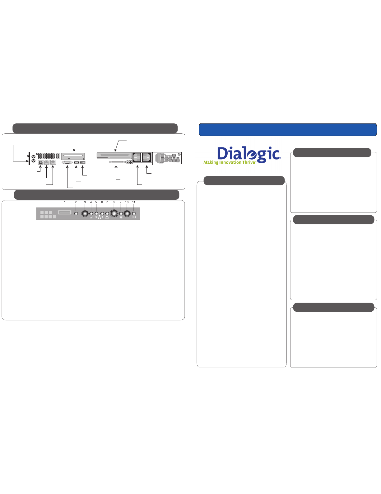
1
2
3
4
5
6
7
8
9
10
11
USB 2.0 port
NMI button
Reset button
Hard disk drive LED
NIC 0 Activity LED
NIC 1 Activity LED
System Status LED
Power/Sleep button
Power/Sleep LED
System Identification button
System Identification LED
Allows you to attach a USB component to the front of the chassis.
Puts the server in a halt-state for diagnostic purposes.
Reboots and initializes the system.
Random blinking green light indicates hard disk drive activity (SCSI).
No light indicates no hard disk drive activity.
Blinking green light indicates network activity.
Continuous green light indicates a link between the system
and the network to which it is connected.
Blinking green light indicates network activity.
Continuous green light indicates a link between the system
and the network to which it is connected.
Solid green indicates normal operation.
Blinking green indicates degraded performance.
Solid amber indicates a critical or non-recoverable condition.
Blinking amber indicates a non-critical condition.
No light indicates POST is running or the system is off.
Toggles the system power on/off.
Continuous green light indicates the system has power applied to it.
Blinking green indicates the system is in S1 sleep state.
No light indicates the power is off / is in ACPI S4 or S5 state.
Toggles the front panel ID LED and the server board ID LED on and off.
Solid or blinking blue indicates system identification is active.
No light indicates system identification is not activated.
Note: The server board LED is visible from the rear of the chassis
and allows you to locate the server from the rear of a rack of systems.
Dialogic® IP Media Server Front Control Panel
Dialogic® IP Media Server Rear View
Copyright 2006-2008, Dialogic Corporation Part Number: 939-018-11
0
1
ID
!
ID
1 2
3 4
5 6 7 8 9 10 11
Mouse
eth0
eth1
Keyboard
Video
SCSI
Half-Height PCI Slot
Serial Port
USB1
USB0
Full-Height PCI Slot
EDP-10 DSP Card (optional)
F - Front
Power Supply
B - Back
Power Supply
(optional)
The integrated Dialogic® IP Media Server is
available with optional components. A second
redundant power supply is available as a factoryinstalled option.
The Dialogic® IP Media Server is also available
with an optional EDP-10 DSP that enables G.726,
G.729, and AMR-NB* codecs. This is a factoryinstalled option, not a field-upgradable option.
Note that although your IP Media Server may
have open disk drive bays, these must not be
upgraded with field-installed drives.
*Use of the AMR-NB resource in connection with a Dialogic® product does
not grant the right to practice the AMR-NB standard. To seek a patent
license agreement to practice the standard, contact the VoiceAge
Corporation at http://www.voiceage.com/licensing.php
www.dialogic.com/support/
Dialogic® IP Media Server Front View
Copyright and Legal Disclaimer
Copyright © 2006-2008 Dialogic Corporation. All Rights Reserved. You may not reproduce this document in whole or in part without permission in writing from Dialogic Corporation at the address provided below. All contents of this
document are furnished for informational use only and are subject to change without notice and do not represent a commitment on the part of Dialogic Corporation or its subsidiaries (“Dialogic”). Reasonable effort is made to ensure the
accuracy of the information contained in the document. However, Dialogic does not warrant the accuracy of this information and cannot accept responsibility for errors, inaccuracies or omissions that may be contained in this document.
INFORMATION IN THIS DOCUMENT IS PROVIDED IN CONNECTION WITH DIALOGIC® PRODUCTS. NO LICENSE, EXPRESS OR IMPLIED, BY ESTOPPEL OR OTHERWISE, TO ANY INTELLECTUAL PROPERTY RIGHTS IS GRANTED BY THIS DOCUMENT.
EXCEPT AS PROVIDED IN A SIGNED AGREEMENT BETWEEN YOU AND DIALOGIC, DIALOGIC ASSUMES NO LIABILITY WHATSOEVER, AND DIALOGIC DISCLAIMS ANY EXPRESS OR IMPLIED WARRANTY, RELATING TO SALE AND/OR USE OF
DIALOGIC PRODUCTS INCLUDING LIABILITY OR WARRANTIES RELATING TO FITNESS FOR A PARTICULAR PURPOSE, MERCHANTABILITY, OR INFRINGEMENT OF ANY INTELLECTUAL PROPERTY RIGHT OF A THIRD PARTY. Dialogic products are
not intended for use in medical, life saving, life sustaining, critical control or safety systems, or in nuclear facility applications. Due to differing national regulations and approval requirements, certain Dialogic products may be suitable for use
only in specific countries, and thus may not function properly in other countries. You are responsible for ensuring that your use of such products occurs only in the countries where such use is suitable. For information on specific products,
contact Dialogic Corporation at the address indicated below or on the web at www.dialogic.com. It is possible that the use or implementation of any one of the concepts, applications, or ideas described in this document, in marketing
collateral produced by or on web pages maintained by Dialogic may infringe one or more patents or other intellectual property rights owned by third parties. Dialogic does not provide any intellectual property licenses with the sale of
Dialogic products other than a license to use such product in accordance with intellectual property owned or validly licensed by Dialogic and no such licenses are provided except pursuant to a signed agreement with Dialogic. More
detailed information about such intellectual property is available from Dialogic’s legal department at 9800 Cavendish Blvd., 5th Floor, Montreal, Quebec, Canada H4M 2V9. Dialogic encourages all users of its products to procure all necessary
intellectual property licenses required to implement any concepts or applications and does not condone or encourage any intellectual property infringement and disclaims any responsibility related thereto. These intellectual property
licenses may differ from country to country and it is the responsibility of those who develop the concepts or applications to be aware of and comply with different national license requirements. Dialogic, Dialogic Pro, Brooktrout, Cantata,
SnowShore, Eicon, Eicon Networks, Eiconcard, Diva, SIPcontrol, Diva ISDN, TruFax, Realblocs, Realcomm 100, NetAccess, Instant ISDN, TRXStream, Exnet, Exnet Connect, EXS, ExchangePlus VSE, Switchkit, N20, Powering The Service-Ready
Network, Vantage, Making Innovation Thrive, Connecting People to Information, Connecting to Growth and Shiva, among others as well as related logos, are either registered trademarks or trademarks of Dialogic. Dialogic's trademarks may
be used publicly only with permission from Dialogic. Such permission may only be granted by Dialogic’s legal department at 9800 Cavendish Blvd., 5th Floor, Montreal, Quebec, Canada H4M 2V9. Any authorized use of Dialogic's trademarks
will be subject to full respect of the trademark guidelines published by Dialogic from time to time and any use of Dialogic’s trademarks requires proper acknowledgement. The names of actual companies and products mentioned herein
Overview
The IP Media Server shipment includes two
boxes. Unpack them and verify that you have
received the following items:
• Chassis
• Bezel
• AC Power Cord(s)
• Hardware Warranty
• Sliding rail kit and installation guide
• Documentation package
• End User License
• CD containing electronic
versions of the documentation
and release notes
1 - Check Package Contents
The IP Media Server comes with sliding rails and
a set of fixed rails for mounting in rack-mount
systems. The configuration of your racks may
dictate which rails you are able to use. Refer to
the installation instructions provided with the rails
for more information.
You must also install the rack-mount handles that
are included with the rails. The rack-mount
handles hold the front bezel in place. The front
bezel includes a lock and key set to prohibit
access to the front panel buttons while allowing
you to view the activity LEDs.
2 - Rack Mount the Server
Contact Information
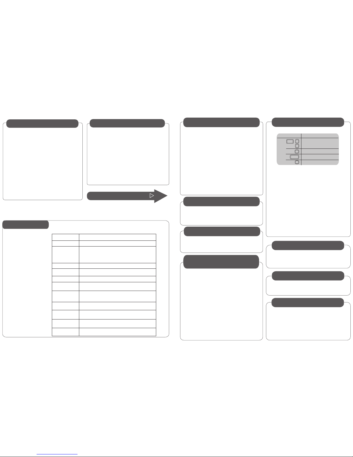
Specifications
Continue to Step 3
Processor
Hard Disk
Ethernet
PCI Slots:
full-height
low-profile
Memory
Power
Weight
Dimensions
Temperature:
Operating
Non-operating
Humidity
Non-operating
Cooling Requirements
Dual Intel Xeon Processors @ 2.8 GHz
Two 1Gb Ethernet Ports (eth0, eth1)
1
1
2GB
Height 1.7", Width 16.93", Depth 26.46"
(43 mm x 430 mm x 672 mm)
+50°F to +95°F
–40°F to +158°F
Single 70GB
Single or dual 520W Power Supplies
AC Voltage: 100–127 / 200–240 V~; 6.5 / 3.2A
90% (non-condensing) @ +30°C
2322 BTU/hour (based on 520W maximum power,
78% power subsystem efficiency, and 98% power factory correction loss)
~28 / 35 lbs
EDP-10 (Optional)
DSP Card for G.726, G.729, and AMR-NB Codec Support
(LED Indicators: On, Active, Transmit Receive)
Network
Cables connect at the rear of the chassis. There are two 1Gb
Ethernet ports and a serial port connector. The standard
Ethernet ports are labeled eth0 and eth1. Refer to the
Dialogic® IP Media Server - Rear View drawing for the
location of each connector.
Power
Note that one model of the IP Media Server has two power
supplies, whereas the other model has a single power
supply. If you have a single power supply system, plug the
power cord into the F- Front Power Supply connector.
Serial Port
The serial port (RJ45 connector) is located to the left of the
Ethernet ports. You can connect the serial port to a terminal
server for alternative access to the system. The default setup
for the serial connection is Rate: 9600 baud, Bits: 8, Parity:
None, Stop Bits: 1, Flow Control: None.
After connecting all cables, power on the system by pressing
the Power button on the front panel. Wait until the system is
fully running, as indicated by the Front Panel LEDs, before
configuring a management interface (described in step 6).
The system is configured to run DHCP on the Ethernet
interfaces (eth0, eth1). If you use DHCP to set the IP
address of an interface and you know the IP address, then
you can use the Web User Interface (Web UI) immediately.
If you do not know the IP address configured on the system
or to set an IP address for the first time, access the system
with a monitor and keyboard or over the serial port. Connect
to the serial port using any standard terminal interface.
When a connection to the IP Media Server is established,
the login prompt appears. The IP Media Server is delivered
with a single administrator access level user defined in the
system. The login prompt appears as follows:
{hostname} login:
Use “admin” as the user name to log into the serial port or
through the console using the Web User Interface (Web UI).
Select the Interface Configuration command.
Specify an IP address for each interface, including eth0 and
eth1.
To change the IP address of an interface:
• Select the interface to be configured.
• Tab to the IP address field.
• Enter an IP address.
• Enter a network mask.
• Make a note of the IP address and apply the change.
The next screen displayed is the original screen you saw when
you logged in. Tab to the REBOOT option and press ENTER.
The IP Media Server reboots and the interface comes up with
the specified addresses. All further configuration is done
through the Web User Interface. The Web User Interface
arrives configured to use HTTP. If HTTPS is preferred, you can
install a security certificate and key on the system using the
Web User Interface.
The IP Media Server must have its license activated in order to
become fully functional. Refer to the License Activation Guide
for information about activating your Dialogic® IP Media Server
license.
Refer to the Dialogic® IP Media Server Installation and Opera-
tions Guide for information about configuring and administering
the IP Media Server.
6 - continued
This equipment contains no user serviceable parts and is not
intended for repair by unauthorized personnel.
If you experience problems with the IP Media Server chassis
and need repair or warranty information, please contact
Dialogic to acquire an RMA number. You may need to send the
IP Media Server to Dialogic for servicing under the RMA
number.
Use the keyboard to navigate through the interface.
H
Description
Navigate through the fields
in the display.
Select an option.
To apply, cancel or reboot.
To access help.
Navigation Key
Enter
7 - Activate License
8 - Configure and Administer
Troubleshooting
6 - Configure a
Management Interface
4 - Apply Power
3 - Connect System Cables
5 - Attach Front Bezel
After pressing the Power button to turn on the IP Media
Server, you should snap the front bezel into place and use
the enclosed keys to lock it. This prevents unauthorized
access to the front panel buttons.
Rack Mounting
Requirements
See the Server Rack Cabinet Compatibility Guide on the
Documentation CD.
5 - Attach Front Bezel
(+10°C to +35°C)
(–40°C to +70°C)
 Loading...