

Installing the EdgeMedia DSP
Board in a Dialogic
®
IP Media
Server
Part Number: 64-0518-01
The EdgeMedia DSP Processor Array (EDP-10)
Plug-in board provides transcoding assistance for the
Dialogic® IP Media Server.
The EDP-10 board is required when the IP Media
Server provides additional functionality to connect to
a non-G.711 network, such as G.726 or G.729.
The EDP-10 board is a transcoding engine
exclusively for use with the IP Media Server and does
not provide a separate TDM or Ethernet interface. It
can be used in a variety of applications such as call
centers, conferencing, pre-paid applications and
messaging platforms.
Operating/Environmental Specifications
This device must be installed in an enclosure that
meets the following electrical and mechanical
requirements:
Power Requirements:
Base: 2A at 5VDC = 10W / 4A at 3.3VDC =
13.2W
Temperature: 0 degree C - 50 degree C
Humidity: 10% - 95% (noncondensing)
Cooling: Direct forced-air flow is required.
MTBF (mean time between failures):
>150,000 hours
Installing the EDP-10 Board
Read the product instructions for installing hardware
and software before installing your board so that you
install them in the proper order.
To install the board:
1. Power off the computer.
2. Remove the computer cover. If the system has a
board hold-down bar, remove that as well.
3. Locate an unused PCI expansion slot and remove
the blank bracket.
4. Holding the board at each top corner, insert the
board firmly into the PCI slot.
5. Screw the board’s mounting bracket securely to
the computer's frame. See Figure 1.
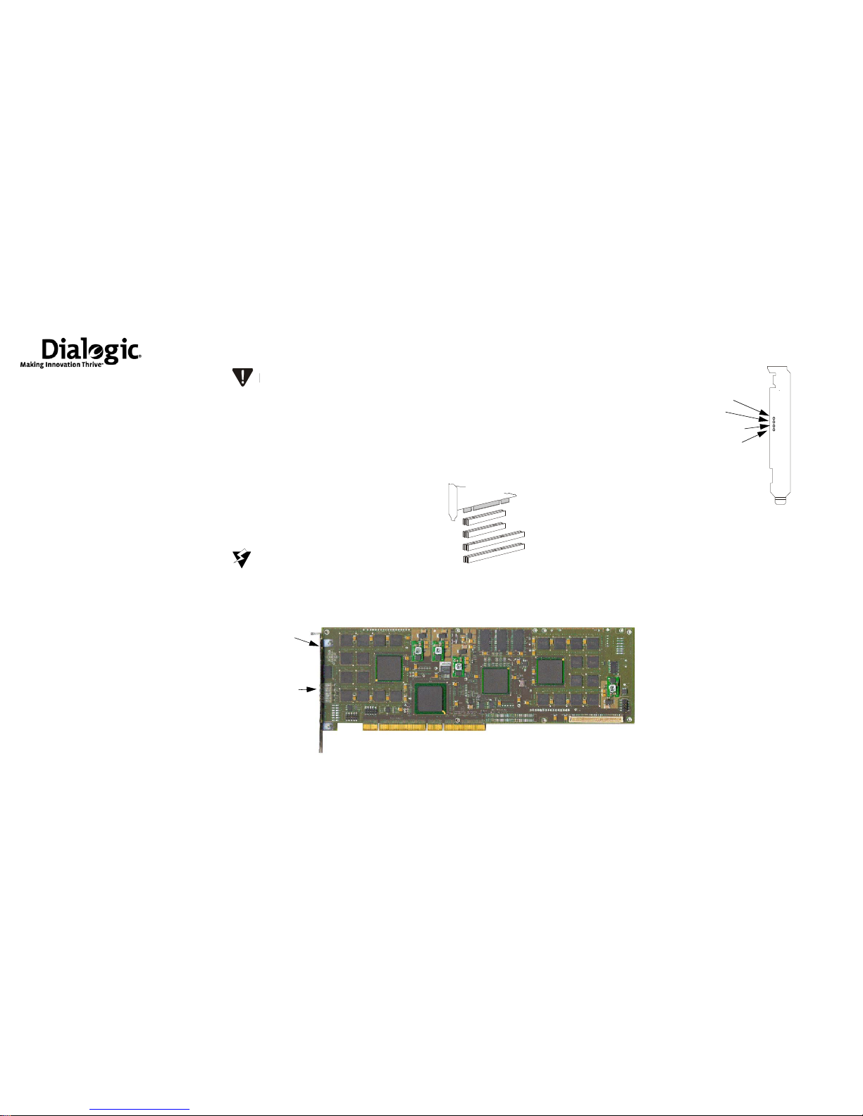
Figure 1. EDP-10 Board
6. Replace the computer cover.
7. Turn on the computer.
The board ON/UP LED should be green.
Recognizing PCI Slots
The EDP-10 board is compliant with the following:
32/64 bit, 33MHz/66MHz, PCI-SIG 2.3 chassis
PCI-X chassis up to 66MHz
The PCI connectors in the computer chassis usually
appear as white slots, unlike ISA connectors, which
are dark brown or black. The different variations of
PCI connectors that can be used with the board are
shown in Figure 2. The board has a Universal PCI
board edge connector. It can be inserted into any of
the PCI slots shown in F i gure2.
Figure 2. PCI Slots
Understanding the LEDs
The EDP-10 board has four LEDs on the mounting
bracket.
Figure 3. Front View of Mounting Bracket
ON/UP LED
This LED is on when the card is powered on, out of
reset, and ready to be used.
Active LED
This LED on when the card is active and the driver
has detected the card.
Ingress Traffic LED
This LED blinks when there is packet traffic coming
into the card.
Egress Traffic LED
This LED blinks when there is packet traffic going
out of the card.
A small amount of static electricity can
destroy the sensitive components on
your board. To prevent static damage,
always connect yourself to ground using
a ground strap before touching a circuit
board. Handle boards only by the edges
or metal mounting brackets and
transport boards in an anti-static bag.
When installing the board, be sure that
the mounting bracket is securely
fastened to the chassis and the chassis
is plugged into a grounded three prong
plug. Improper chassis or bracket
grounding can result in harmful or fatal
electrical shock as well as component
damage.
Mounting Bracket
LEDs on the Bracket
PCI Connector
5V 64-Bit Connector
3.3V 32-Bit Connector
Insert the connector into any of these slots.
3.3V 64-Bit Connector
5V 32-Bit Connector
Universal PCI Board Edge Connector
C
onnector B
Board Status LED
Channel LEDs
Connector A
A
B
BOARD
STATUS
CHANNEL
1
3
5
7
0
2
4
6
Ingress traffic LED
Active LED
ON/UP LED
Egress traffic LED

Safety Compliance Statements
The following customer information must be provided
to customers with each product.
The statements provided below should be
conspicuously located in the end user system
documentation:
United States of America and Canada
This product is listed by Underwriters Laboratories, a
Nationally Recognized Test Laboratory (NRTL). The
Listing Mark is located on the bottom surface of the
board. The product has been tested and complies with
UL 60950 and CAN/CSA-C22.2 No. 60950, Safety of
Information Tec hno lo gy Equi p ment, Including
Electrical Business Equipment.
This card is for use only with compatible UL or
equivalent NRTL Listed personal computers/servers
that have installation instructions detailing user
installation of card cage accessories.
This product must be mounted in the final assembly so
that it is isolated from exposure to any hazardous
voltages (voltages greater than 42.4V peak or 60Vdc)
within the assembly. Adequate separation and restraint
of cables and cords must be provided.
Users should ensure for their own protection that the
electrical ground connections of the power utility,
telephone lines and internal metallic water pipe system,
if present, are connected together. This precaution may
be particularly important in rural areas.
Getting Help
If you have a problem installing your board, first check
with the provider of your board to determine if there is a
problem. If your provider cannot solve your problem,
then contact Dialogic Technical Support.
Dialogic Technical Support
Dialogic provides technical support for customers who
have purchased the EDP-10 from Dialogic. If you
purchased products from a reseller, please contact that
reseller for technical support.
This equipment contains no user-serviceable parts and
is not intended for repair by unauthorized personnel.
If you experience trouble with the board, for repair or
warranty information, please go to the following
Dialogic web site:
www.dialogic.com/support/
Declaration of Conformity
For product declaration of conformity, refer to the
following Dialogic web site. (Select Product: Media
Server with EDP-10-R.)
http://www.dialogic.com/declarations/default.htm
Copyright and Legal Disclaimer
Copyright © 2006-2009 Dialogic Corporation. All Rights
Reserved. You may not reproduce this document in whole or
in part without permission in writing from Dialogic
Corporation at the address provided below.
All contents of this document are furnished for informational
use only and are subject to change without notice and do not
represent a commitment on the part of Dialogic Corporation or
its subsidiaries (“Dialogic”). Reasonable effort is made to
ensure the accuracy of the information containe d in the
document. However, Dialogic does not warrant the accuracy
of this information and cannot accept responsibility for errors,
inaccuracies or omissions that may be contained in this
document.
INFORMATION IN THIS DOCUMENT IS PROVIDED IN
CONNECTION WITH DIALOGIC® PRODUCTS. NO
LICENSE, EXPRESS OR IMPLIED, BY ESTOPPEL OR
OTHERWISE, TO ANY INTELLECTUAL PROPERTY
RIGHTS IS GRANTED BY THIS DOCUMENT. EXCEPT
AS PROVIDED IN A SIGNED AGREEMENT BETWEEN
YOU AND DIALOGIC, DIALOGIC ASSUMES NO
LIABILITY WHATSOEVER, AND DIALOGIC
DISCLAIMS ANY EXPRESS OR IMPLIED WARRANTY,
RELATING TO SALE AND/OR USE OF DIALOGIC
PRODUCTS INCLUDING LIABILITY OR WARRANTIES
RELATING T O FITNESS FOR A P AR TICULAR PURPOSE,
MERCHANTABILITY, OR INFRINGEMENT OF ANY
INTELLECTUAL PROPERTY RIGHT OF A THIRD
PART Y.
Dialogic products are not intended for use in medical, life
saving, life sustaining, critical control or safety systems, or in
nuclear facility applications.
Due to differing nationa l regu la tio ns and approval
requirements, certain Dialogic products may be suitable for
use only in specific countries, and thus may not function
properly in other countrie s. You are resp on s ible for ensuring
that your use of such products occurs only in the countries
where such use is suitable. For information on specific
products, contact Dialogic Corporation at the address
indicated below or on the web at www.dialogic.com.
It is possible that the use or implementa tio n of an y on e of the
concepts, applications, or ideas described in thi s docu men t, in
marketing collateral produced by or on web pages mainta in ed
by Dialogic may infringe one or more patents or other
intellectual property rights owned by third parties. Dialogic
does not provide any intellectual property licenses with the
sale of Dialogic products other than a license to use su ch
product in accordance with intellectual property ow ned or
validly licensed by Dialogic and no such licenses are provided
except pursuant to a signed agreement with Dialogic. More
detailed information about such intellectual property is
available from Dialogic’s legal department at 9800 Cavendish
Blvd., 5th Floor, Montreal, Quebec, Canada H4M 2V9.
Dialogic encourages all users of its pr o d u ct s to procure all
necessary intellectual property licenses required to
implement any concepts or applications and does not
condone or encourage any intellectual property
infringement and disclaims any responsibility related
thereto. These intellectual property licenses may differ
from country to country a nd it is the r esponsib ility of tho se
who develop the concepts or applications to be aware of
and comply with different national license requirements.
Dialogic, Dialogic Pro, Brooktr out, Diva, Cantata,
SnowShore, Eicon, Eicon Networks, NMS Communications,
NMS (stylized), Eiconcard, SIPcontrol, Diva ISDN, TruFax,
Exnet, EXS, SwitchKit, N20, Making Innovation Thrive,
Connecting to Growth, Video is the New Voice, Fusion,
Vision, PacketMedia, NaturalAccess, NaturalCallControl,
NaturalConference, NaturalFax and Shiva, among others as
well as related logos, are either registered trademarks or
trademarks of Dialogic Corporation or its subsidiaries.
Dialogic's trademarks may be used publicly only with
permission from Dialogic. Such permission may only be
granted by Dialogic's legal department at 9800 Cavendish
Blvd., 5th Floor, Montreal, Quebec, Canada H4M 2V9. Any
authorized use of Dialogic's trademarks will be subject to full
respect of the trademark guidelines published by Dialogic
from time to time and any use of Dialogic's trademarks
requires proper acknowledg e ment.The names of actual
companies and products mentioned herein are the trademarks
of their respective owners.
To maintain the safety certification of
the system, ensure that the power drawn
from the power supply does not exceed
its capacity. Please refer to the power
usage table on this hardware installation
card for information on the voltages and
currents required for proper operation.
Users should not attempt to make such
connections themselves, but should
contact the appropriate electric
inspection authority, or electrician, as
appropriate.
 Loading...