

Page 1

Dialogic® Diva® Media Board
Installation Guide
Dialogic® Diva® Karten
Installationsanleitung
Adaptadores Dialogic® Diva
Guía de Instalación
January 2014 203-195-18, Rev B
www.dialogic.com
®
Page 2

Copyright and Legal Notice
Copyright © 1999-2014 Dialogic Inc. All Rights Reserved. You may not reproduce this document in
whole or in part without permission in writing from Dialogic Inc. at the address provided below.
All contents of this document are furnished for informational use only and are subject to change without
notice and do not represent a commitment on the part of Dialogic Inc. and its affiliates or subsidiaries
(“Dialogic”). Reasonable effort is made to ensure the accuracy of the information contained in the
document. However, Dialogic does not warrant the accuracy of this information and cannot accept
responsibility for errors, inaccuracies or omissions that may be contained in this document.
INFORMATION IN THIS DOCUMENT IS PROVIDED IN CONNECTION WITH DIALOGIC
LICENSE, EXPRESS OR IMPLIED, BY ESTOPPEL OR OTHERWISE, TO ANY INTELLECTUAL PROPERTY
RIGHTS IS GRANTED BY THIS DOCUMENT. EXCEPT AS PROVIDED IN A S IGNED AGREEME NT BETWEEN
YOU AND DIALOGIC, DIALOGIC ASSUMES NO LIABILITY WHATSOEVER, AND DIALOGIC DISCLAIMS
ANY EXPRESS OR IMPLIED WARRANTY, RELATING TO SALE AND/OR USE OF DIALOGIC PRODUCTS
INCLUDING LIABILITY OR WARRANTIES RELATING TO FITNESS FOR A PARTICULAR PURPOSE,
MERCHANTABILITY, OR INFRINGEMENT OF ANY INTELLECTUAL PROPERTY RIGHT OF A THIRD PARTY.
Dialogic products are not intended for use in certain safety-affecting situations. Please see
http://www.dialogic.com/company/terms-of-use.aspx for more details.
Due to differing national regulations and approval requirements, certain Dialogic products may be
suitable for use only in specific countries, and thus may not function properly in other countries. You
are responsible for ensuring that your use of such products occurs only in the countries where such use
is suitable. For i nformation on specific products , contact D ialogic In c. at the a ddress indic ated belo w or
on the web at www.dialogic.com.
It is possible that the use or impl ementation of any one of the c oncepts, applications , or ideas described
in this document, in marketing collateral produced by or on web pages maintained by Dialogic may
infringe one or more patents or other intellectual property rights owned by third parties. Dialogic does
not provide any intellect ual prop erty licenses wit h the sale of Dialogic products other tha n a license to
use such product in accordance with intellectual property owned or validly licensed by Dialogic and no
such licenses are provided except pursua nt to a signed agreement with Dialogic. More detailed
information about such i ntellect ual p roperty is av ail able from D ialogic’s legal department at 6700 de la
Cote-de-Liesse Road, Suite 100, Borough of Saint-Laurent, Montreal, Quebec, Canada H4T 2B5.
Dialogic encourages all users of its products to procure all necessary intellectual property
licenses required to implement any concepts or applications and does not condone or
encourage any intellectual property infringement and disclaims any responsibility related
thereto. These intellectual property licenses may differ from country to country and it is the
responsibility of those who develop the concepts or applications to be aware of and comply
with different national license requirements.
Dialogic, Dialogic Pro, Dialogic Blue, Veraz, Brooktrout, Diva, BorderNet, PowerMedia, ControlSwitch,
I-Gate, Mobile Experience Matters, Network Fuel, Video is the New Voice, Making Innovation Thrive,
Diastar, Can tata, TruFax, SwitchKit, Eiconcard, NMS Communications, SIPcontrol, Exnet, EXS, Vision,
inCloud9, NaturalAccess and Shiva, among others as well as related logos, are either registered
trademarks or trademarks of Dialogic Inc. and its affiliates or subsidiaries. Dialogic’s trademarks may
be used publicly only with permission from Dialogic. Such permission may only be granted by Dialogic’s
legal department at 6700 de la Cote-de-Liesse Road, Suite 100, Borough of Saint-Laurent, Montreal,
Quebec, Canada H4T 2B5. Any autho rized use of Dialog ic’ s trademark s will be subject to full respec t of
the trademark guidelines published by Dialogic from time to time and any use of Dialogic’s trademarks
requires proper acknowledgement.
The names of actual companies and products mentioned herein are the trademarks of their respective
owners.
®
PRODUCTS. NO
Revision Release Date Notes
203-195-18, Rev B January 2014 PKN
page 2
Page 3

License Agreement for Use of Software
This is an Agreement between you, the Company, and your Affiliates (referred to in some
instances as "You" and in other instances as "Company") and all Y our Autho rized Users
and Dialogic Inc. ("Dialogic").
YOU SHOULD CAREFULLY READ THE SOFTWARE LICENSE AGREEMENT ("AGREEMENT")
ON THIS SEALED PACKAGE BEF ORE OPENING THE PACKAGE. BY OPENING THE PACKAGE ,
YOU ACCEPT THE TERMS AND CONDITI ONS OF THIS AGREEMENT . IF YOU DO NOT AGREE
WITH OR ARE UNWILLING TO ACCEPT THESE TERMS AND CONDITIONS, YOU MAY
RETURN THE PACKAGE IN UNOPENED "AS NEW" CONDITION (INCLUDING ALL
DOCUMENTATION AND BINDERS OR OTHER CONTAINERS) FOR A FULL REFUND. BY
DOWNLOADING, INSTALLING, COPYING OR OTHERWISE USING THE ENCLOSED
SOFTWARE ("PROGRAM"), YOU FURTHER AGREE AND ACKNOWLEDGE THAT YOU HAVE
READ THIS AGREEMENT AND UNDERST AND IT , AND THAT BY T AKING ANY ONE OR MORE
OF SUCH STEPS/ACTIONS YOU AGRE E TO BE BOUND BY SUCH TERMS AND CONDITIONS.
DIALOGIC IS UNWILLI NG TO LICEN SE THE SOFTW ARE T O Y OU IF YOU DO NO T ACCEPT
AND AGREE TO BE BOUND BY THE TERMS AND CONDITIONS OF THIS AGREEMENT.
Intellectual Property
The enclosed Software ("Program") and all accompanying documentation are individually
and collectively owned by Dialogic Inc. ("Dialogic"), its subsidiaries and/or its suppliers
and are protected by all applicable intellectual property laws and international treaty
provisions. Therefore, You and Your Authorized Users must treat the Pr ogram and
documentation like any other material so protected, except as expressly permitted in this
Agreement. In particular , but without limitation, You acknowledge that the Program and
its accompanying documentation constitute valuable intellectual property rights,
including without limitation trade secrets and copyrights, and confidential inf ormation of
Dialogic. The Program and all programs developed thereunder and all copies thereof
(including without limitation translations, compilations, partial copies with modifications
and updated works) are proprietary to Dialogic and title to all applicable copyrights, trade
secrets, patents and other intellectual property rights therein remains in Dialogic, its
subsidiaries, and/or its suppliers. Except as expressly permitted in this Agreement, You
shall not sell, transfer , publish, disclose, display or otherwise make available the Program
or copies thereof to others. You agree to secure and protect the Program, its
accompanying documentation and copies thereof in a manner consistent with the
maintenance of Dialogic's rights therein and to take appropriate action by instruction o r
agreement with Your employees and/or consultants who are permitted access to the
Program to satisfy Y our obligations hereunder. Violation of any provision of this paragraph
shall be the basis for immediate termination of this Agreement. Because unauthorized
use or transfer of the Software or documentation may diminish substantially the value
of such materials and irrevocably harm Dialogic, if You breach the provisions of this
Section of this Agreement, Dialogic shall be entitled to injunctive and/or other equitable
relief, in addition to other remedies afford ed by law, to prevent a breach of this Section
of this Agreement.
Grant of License
Subject to the terms and conditions of this Agreement Dialogic grants to You a
non-exclusive, personal, non-transferable license to use the Program in object code form
only and solely in accordance with the following terms and conditions:
• You may make, install and use only one (1) copy of the Program on a single-us er
computer , file server , or on a workstation of a local area network, and only in conjunction
with a legally acquired Dialogic
copy solely for backup or archive purposes;
• The primary Authorized Us er on the c om puter on which the Program is installed may
make a second copy for his/her exclusive use on either a home or portable c omputer;
• You may copy the Program into any machine readable or printed form for backup or
modification purposes in support of Your use of one copy of the Program;
®
hardware or software product Y ou may also make one
page 3
Page 4

License Agreement for Use of Software
• You may distribute the Program in object code only and only as part of, or integrated
by You into, a computer system that (i) contains a Dialogic hardware product, (ii)
includes a substantial amount of other software and/or hardware manufactured or
marketed by You and (iii) is marketed and sublicensed to an end user for the end user's
own internal use in the regular course of business (a "Licensed System");
• Each end user to whom a Licensed System is distributed must agree to license terms
with respect to the Program that are at least as protective of Dialogic's rights in the
Program as those set forth in this Agreement;
• You shall receive one (1) Program master disk, and shall be solely responsible for
copying the Program into the Licensed Systems and for warranting the physical media
on which it is copied;
• You ma y make one (1) copy of the documentation accompan ying the Program, pro vided
that all copyright notices contained within the documentation are retained;
• You may modify the Program and/or merge it into another Program for Your use in one
computer; (any portion of this Program will continue to be subject to the terms and
conditions of this Agreement);
• You may tr ansfer th e Progr am, docume ntation and the lice nse to another eligible party
within Your Company if the other party agrees to accept the terms and conditions of
this Agreement. If You transfer the Program and documentation, Y ou must at the same
time either transfer all copies whether in printed or machine readable form to the same
party or destroy any copies not transferred; this includes all modifications and portions
of the Program contained in or merged into other Programs;
• You shall not remove, and each copy of the Program shall contain, the same copyright,
proprietary, patent and/or other applicable intellectual property or other ownership
notices, plus any restricted rights legends that appear in the Program and/or this
Agreement and, if You copy the Program onto media to which a label may be attached,
You shall attach a label to the media that includes all such notices and legends that
appear on the Program master disk and envelope;
• You ma y not rent or lease the Program. You may not reverse engineer, decompile or
disassemble the Program. Except as is strictly necessary for You to integrate the
Program with other software and/or hardware to produce the Licensed Systems, You
shall not copy, modify or reproduce the Program or documentation in any way. You
shall use Yo ur best efforts to ensure that any user of the Program does not reverse
engineer, decompile or disassemble the Program to de rive a source code equiv alent of
the Program;
• If You transfer possession of any copy, modification or merged portion of the Program
or documentation to another party in any way other than as expressly permitted in this
Agreement, this license is immediately and automatically terminated;
• The Program may be used only in conjunction with Dialogic hardware;
• The Program shall not be e xported or re-exported in violation of any export provisions
of the United States or any other applicable jurisdiction.
Upgrades
If the Program is provided as an upgrade and the upgrade is an upgrade from another
product licensed to Y ou and Y our Autho rized Users by Dialog ic, the upgrad e is governed
by the license agreement earlier provided with that software product package and the
present Agreement does not g rant You additional license(s). If Y ou and Your Authorized
Users choose to upgrade this Program or the product used together with the Program
and such upgrade requires the license of additional software (whether a charge is
associated with such soft wa re or n ot ), th e licen se ag ree m ent a sso cia te d wit h su ch
additiona l so f tw a re sha ll g ov er n t he l ice n se of su ch a ddi ti on al soft w ar e to th e ex cl u sio n
of this Agreement.
page 4
Page 5

Term
The Agreement is effective until terminated. You may terminate it at any time by notifying
Dialogic and/or by destroying the Program and all accompanying documentation together
with all copies, modifications and merged portions in any form. The Agreement will also
terminate automatically upon the occurrence or lack of occurrence of certain terms and/or
conditions set forth in this Agreement, or if You fail to comply with any term or condition
of this Agreement. You agree that upon any such terminatio n Y ou shall destroy or return
to Dialogic the Program and all accompanying documentation supplied by Dialogic,
together with any and a ll copies, modifications and merged portions in any form. All
provisions of this Agreement relating to disclaimers of warranties, limitation of liability,
remedies, or damages, and licensor's proprietary rights shall survive termination.
Limited Warranty
Dialogic solely warrants the media on which the Program is furnished to You to be free
from defects in materials and workmanship under normal use for a period of ninety (90)
days from the date of purchase by You as evidenced by a copy of Your receipt. If such a
defect appears within the warranty period, You may return the defective media to Dialogic
for replacement without charge provided Dialogic, in good faith, determines that it was
defective in materials or workmanship. Replacement is Your sole remedy with respect to
such a defect. Dial ogic offers no warranty for Your reproduct ion of the Program. This
Limited Warranty is void if failure of the Program has resulted from accide n t, misuse,
abuse or misapplication.
Disclaimers, Limitations of Liability and Customer Remedies
Except as set forth in the "Limited Warranty " Section of this Agreement, the Program and
accompanying documentation are provided to You "as is." Neither Dialogic, its
subsidiaries, its suppliers, nor its licensor(s) (if any) warrants that the Program will meet
Your requirements or that its use will be uninterrupted or error- free. Ex cept as set forth
in the "Limited Warranty" Section, EACH OF DIALOGIC, ITS SUBSIDIARIES, ITS
SUPPLIERS AND ITS LICE NSOR(S) (IF ANY) DISCLAIMS ANY AND A LL REPRESENTA TIONS
AND WARRANTIES, EXPRESS OR IMPLIED, WITH RESPECT TO THE PROGRAM AND
ACCOMPANYING DOCUMENTATION, INCLU DIN G BUT NOT LIMITED TO THE IMPLIED
WARRANTIES OF NON-INFRINGEMEN T , MERCHANT ABILITY, FITNESS FOR A PAR TICULAR
PURPOSE, OR AGAINST LATENT DEFECTS. Ex cept as set forth in the "Limited W arrant y"
Section, neither Dialogic, its subsidiaries, its supp liers, nor its licensor(s) (if any) shall
have any liability to You or any third party for any claim, loss or damage of any kind,
including but not limited to lost business profits, business interruption, loss of information,
or other pecuniary loss and indirect, punitive, incidental, economic, consequential or
special damages, arising out of or in connection with this Agreement and/or the use,
inability to use the Program and/or the Program's performance or inability to perform nor
from or in connection with the Program's accompan ying documentation, or any data or
equipment related thereto or used i n conn ection th erew ith. In no even t shall Di alogic 's,
its subsidiaries', its suppliers' or its licensor(s)'s liability for damages, whether arising
out of contract, negligence, warranty, or patent or copyright infringement, exceed the
fees You p aid for the Program. No re presentation or warranty re garding the Program may
be made without Dialogic's, its subsidiaries', its suppliers', or its licensor(s)'s (if any) prior
written consent, and any warranty or representation made by You or Your customers
regarding the Program shall not constitute an obligation of Dialogic, its subsidiaries, its
suppliers, or other licensor(s) (if any). This limited warranty gives You specific legal rights.
You may have othe r rights, which may vary from jurisdiction to jurisdiction. Also, as some
jurisdictions do not allow th e exclu sion or lim ita ti on for ce r ta in dama ge s, some of the
above limitations may not apply to You.
page 5
Page 6

License Agreement for Use of Software
Right to Audit
If this Program is licensed for use in a Company, Y our Company and Y ou individually and
collectively agree to keep all usual and proper records and books of accounts and all usual
proper entries relating to each installation of the Program during the term of this
Agreement and for a period of three (3) years th ereafter . During this period, Di alogic may
cause an audit to be made of the applicable records in order to verify Your compliance
with this Agreement and prompt adjustment shall be made to compensate for any errors
or omissions disclosed by such audit. Any such audit shall be conducted by an independent
certified public accountant selected by Dialogic and shall be conducted during the regular
business hours at Your offices and in such a manner as not to interfere with Y our normal
business activities. Any such audit shall be paid for by Dialogic unless material
discrepan cies are disc losed. For such purposes , "material di screpancie s" shall mean t hree
percent (3%) or more of the Authorized Users within the Company. If material
discrepan cies are disclosed, You r Company agrees to pay Dia logic for the cost s associa ted
with the audit as well as the li cense fees for the addition al licensed channels or additional
authorized users. In no event shall audits be made more f requently than s emi-a nnually
unless the immediately preceding audit disclosed a mate ria l discre pancy.
Supplementary So ftware
Any Supplementary Software provided with the Program and/or referred to in this
Agreement is provided "as is" with no warranty of any kind.
Miscellaneous
You acknowledge that You have read this Agreement, that You understand it, and that
You agree to be bound by its terms and conditions, and You further agree that this is the
complete and exclusive stat ement of the Agreement between the Dialogic and Y o u ("the
Parties"), which supersedes and merges all prior proposals, understandings and all other
agreements, oral and written, between the Part ies relating to the Program. You agree to
indemnify and hold harmless Dialogic and its subsidiaries, affiliates , suppliers, office rs,
directors and employees from and against any claim, injury, loss or expense, including
reasonable attorneys' fees, arising out of (i) Y our failure to comply with the provisions of
this Agreement, or (ii) any other wrongful conduct by or on behalf of Y ou. This Agreement
applies to all updates, future releases, modifica tion s and portion s of the Pr ogram
contained in or merged into other programs. This Agreement may not be modified or
altered except by written instrument duly executed by Dialogic. No action, regardless of
form, arising out of this Agreement or the use of the Program may be brought by You
more than two (2) years after the cause of action has first arisen. Except as provided
herein, neither this Agreement nor any ri ghts granted are assignable or tr ansferable, and
any assignment or transfer will be null and void. If You authorize any other person to
copy the Program, You shall oblig ate that person in w riting to comply with al l conditions
of this Agreement. Dialogic shall have the right to collect from You its reasonable expenses
incurred in enforcing this agreement, including attorney's fees. The w a i ver or failure of
Dialogic to exercise in any respect any right provided for herein shall not be deemed a
waiver of any further right hereunder. All rights and remedies, whether conferred
hereunder or by any other instrument or law, will be cumulative and may be exercised
singularly or concurrently. Failure by either Dialogic or You to enforce any term or
condition of the Agreement will not be deemed a waiver of future enforcement of that or
any other term or conditions. The terms and conditions stated herein are declared to be
severable. Should any term(s) or condition(s) of this Agreement be held to be invalid or
unenforceable the validity, construction and enforceability of the remaining terms and
conditions of this Agreement shall not be affected. It is expressly agreed that Dialogic
and You are act i ng as i nd ep end ent contractors under this Agreement. These terms and
conditions will prevail notwithstanding any different, conflicting or additional terms and
conditions that may appear on any other agreement between Dialogic and Y ou. Deviations
from these terms and conditions are not valid unless agreed to in writing in advance by
an authorized representative of Dialogic. Any notices sent to Dialogic under this
Agreement must be sent by registered mail or courier to the attention of Dialogic's legal
department at the address below or such othe r add ress as may be listed on
www.dialogic.com from time to time as being Dialogic's Montreal headquarters.
page 6
Page 7

U.S. Government Restricted Rights
The Program and all accompanying documentation are provided with RESTRICTED
RIGHTS. Use, duplication or disclosure by the U.S. Government is subject to restrictions
as set forth in subparagraph (c)(1)(iii) of The Rights in Technical Data and Computer
Software clause at DFARS 252.227-7013 or subparagraph (c) (1) and (2) of the
Commercial Computer Software-Restricted Rights at 48 CFR52.227-19, both as
applicable.
Governing Law
Any and all claims arising under this Agreement shall be construed and controlled by the
laws in force in the Province of Quebec, Canada, excl uding its principles of conflict of laws
and the United Nations Convention on Contracts for the Sale of Goods. Dialogic is not
obligated under any other agreements unless they are in writing and signed by an
authorized representative of Dialogic.
Contractor/ manufacturer is:
Dialogic Inc.
6700 de la Cote-de-Liesse Road, Suite 100, Borough of Saint-Laurent, Montreal, Quebec,
Canada H4T 2B5
This Agreement has been drafted in English at the express wish of the parties. Ce contrat
a été rédigé en anglais à la demande express e des par ties .
Hardware Limited Warranty
Warranty for Hardware Products: Dialogic Inc. or its subsidiary that originally sold
the hardware product to you ("Dialogic") warrants to the original purchaser ("Purchaser")
of this hardware product ("Product"), that at the time of delivery the Product supplied
hereunder will be free from defects in material and workmanship. This warranty is for
the standard period for such Product set out on Dialogic's website at
http://www.dialogic.com/warranties at the date of purchase, provided the Product
remains unmodified, is operated under normal and proper conditions in accordance with
its published specifications and documentat ion , an d the sys t em is not op ene d by
unauthorized personnel. The warr anty is also void if the defect has re sulted from accident,
misuse, abuse or misapplication. Any Product which becomes defective during the
warranty period and is returned by Purchaser to Dialogic's Authorized Service Center
shipping prepaid with a Return Material Authorization (RMA) number (which must be
obtained from Dialogic before any return) within thirty (30) days after discovery of the
defect, with a written description of the defect, will be repaired or replaced at Dialogic's
option. Dialogic will not accept C.O.D. shipments. Dialogic reserves the right to refuse to
repair or replace any Product which show s signs of abuse, misuse, neglect or has be en
altered in any way , including but not limited to Products which have been (i) used in
environments which exceed operating tolerances such as supplied voltages and signals
or (ii) stored under improper temperature or humidity conditions or (iii) used with
equipment, software or interfacing not furnished by Dialogic or (iv) improperly packaged
or shipped or (v) harmed by Purchaser or its agents' fault or negligence or (vi) repaired
or modified without Dialogic's prior written consent . Purchaser must exercise proper
electrostatic discharge (ESD) precautions and pack the Product and the other returned
diagnostic information in the original Dialogic packaging, including the antistatic
bag/container and an ESD foam-filled cardboard box. Purchaser may void the
warranty if the Product is improperly packaged or ship ped. Dialogic will bear the
cost to return the repaired or replaced Product to the location specified on the Return
Material Authorization (RMA) form by a method it chooses. If the Purchaser desires a
specific form of conveyance, the Purchase r must be a r the cost of sh ipm e n t . All risk of
loss shall be with the Purchaser during any and all shipments of the Product. Duties and
import fees are the responsibility of the Pu rchas er.
page 7
Page 8

Hardware Limited Warranty
Additional Exclusions: Dialogic will have no obligation to make repairs or replacements
to the Product due to causes beyond the control of Dialogic, including, but not limited to,
power or air conditioning failure, acts of God, improper interface with other units, or
malfunction of any equipment or software used with the Dialogic Product(s). If Dialogic
is requested and agrees to make repairs or replacements necessitated by any such
causes, Purchaser will pay for such service or replacement at Dialogic's then prevailing
rates.
No Other Warranties: DIALOGIC DISCLAIMS AND PURCHASER WAIVES ALL OTHER
WARRANTIES, EITHER EXPRESS OR IMPLIED, I NCLUDING BUT NOT LIMITED TO IMPLIED
WARRANTIES OF MERCHANTABILITY, NON-INFRINGEMENT AND FITNESS FOR A
PARTICUL AR PURPOSE AND ANY WARRANTY AGAI NST LATENT DEFEC TS, WITH RESPECT
TO ANY DIALOGIC PRODUCT.
No Liability for Damages: IN NO EVENT SHALL DIALOGIC OR ITS SUPPLIER S BE
LIABLE FOR ANY DAMAGES WHATSOEVER (INCLUDING, WITHOUT LIMITATION,
DAMAGES FOR LOSS OF PROFITS, IN TERRUPTION OF ACTIVITIES, LOSS OF
INFORMATION OR OTHER PECUNIARY LOSS AND DIRECT OR INDIRECT,
CONSEQUENTIAL, INCIDENTAL, ECONOMIC OR PUNITIVE DAMAGES) ARISING OU T OF
THE USE OF OR INABILITY TO USE ANY DIALOGIC PRODUCT.
Limitation of Liability: DIALOGIC'S MAXIMUM CUMULATIVE LIABILITY SHALL BE
LIMITED TO THE AMOUNTS ACTUALLY PAID BY PURCHASER TO DIALOGIC FOR THE
SPECIFIC PRODUCT BEING THE OBJECT OF THE CL AIM. PURCHASER RELEASES
DIALOGIC FROM ALL AMOUNTS IN EXCESS OF THE LIMITATION. PURCHASER
ACKNOWLEDGES THA T THIS CONDITION IS ESSENTIAL AND THAT DIALOGIC WOULD
NOT SUPPLY TO PURCHASER IF IT WERE NOT INCLUDED. THIS WARRANTY EXPRESSLY
DOES NOT APPLY TO ANYONE OTHER THAN PURCHASER.
page 8
Page 9

Contents
ENGLISH
Copyright and Legal Notice..................... ...............................2
License Agreement for Use of Sof tware ...................................3
Hardware Limited Warranty ........ ...........................................7
Supported Dialogic® Diva® Media Boards.............................11
Supported Operating Systems .............................................. 13
Dialogic® Diva® Online Documentation ................................13
General Safety Instructions .................................................14
Line Provisioning and Configuration for
Dialogic® Diva® PRI Media Boards.......................................16
Ordering Your ISDN PRI or T1 Line in North America...............16
Ordering Your Analog Line in North America...........................19
Before You Start ................................................................20
Installation........................................................................21
Troubleshooting .................................................................36
Technical Specifications.......................................................42
International Regulatory Informatio n ............................. .... ... 52
Suppliers Declaration of Conformity......................................68
Customer Service...............................................................68
DEUTSCH
Unterstützte Dialogic® Diva® Karten... .... ... .......................... 71
Unterstützte Betriebssyste m e ..............................................73
Dialogic® Diva® Online-Dokumentation................................73
Allgemeine Sicherheitshinweise............................................74
Vorbereitungen..................................................................76
page 9
Page 10

Installation ....................................................................... 77
Problembehandlung ........................................................... 92
Techn isch e Dat e n.... .... ....................................................... 98
Zulassungsinformationen .................................................. 108
Kundendienst .................................................................. 109
Umweltinformationen für Ihr Dialogic® Produkt ................... 111
ESPAÑOL
Adaptadores Dialogic® Diva® disponibles ........................... 113
Sistemas Operativos......................................................... 115
Dialogic® Diva® Documentación Online ............................. 115
Instrucciones de Seguridad ............................................... 116
Preparativos.................................................................... 118
Instalación...................................................................... 119
Problemas y Soluciones .......... .......................................... 133
Datos Técnicos ................................................................ 139
Soporte Técnico............................................................... 150
Información Medioambiental Para Su Producto..................... 152
page 10
Page 11

Dialogic® Diva® Media Board Installation Guide
Dialogic® Diva® Media Board Installation Guide
The Dialogic® Diva® Media Boards provi de high-speed digital or analog
connections to support a variety of network applications. This installation guide
describes how to ph ysic a lly in st all a nd c on ne c t you r Di va Med ia Board,
provides information about technical specif ications, and give s an overview of
the available online doc um e n ta t ion .
Supported Dialogic® Diva® Media Boards
The Dialogic® Diva® product range comprises the following Diva Media
Boards:
Dialogic® Diva® BRI Media Boards
Diva BRI Media Boards are high-performance, partly active PC-based server
boards that provide digital, analog, and GSM connections over an ISDN line.
Diva BRI PCI: Diva BRI PCIe:
• Diva BRI-CTI • Diva BRI-2 PCIe
• Diva BRI-2FX • Diva 4BRI-8 PCIe
•Diva BRI-2 •Diva UM-BRI-2 PCIe
•Diva 4BRI-8 •Diva UM-4BRI-8 PCIe
ENGLISH
•Diva UM-BRI-2
•Diva UM-4BRI-8
Dialogic® Diva® PRI, E1, and T1 Media Boards
These Diva Media Boards are active server boards that provide both digital
and analog connectivity for the ISDN Primary Rate Interface (PRI), E1, and
T1 lines. The Diva multiport Media Boards provide rich media processing
capabilities for up to 120 voice channels over E1 interfaces, or up to 96 voice
channels over T1 int er fac e s .
Diva PRI PCI: Diva V-PRI PCI: Diva V-xPRI PCI:
• Diva PRI/E1/T1-CTI • Diva V-PRI/T1-24 • Diva V-2PRI/T1-48
• Diva PRI/E1/T1-8 • Diva V-PRI/E1-30 • Diva V-2PRI/E1-60
• Diva PRI/T1-24 • Diva V-4PRI/T1-96
• Diva PRI/E1-30 • Diva V-4PRI/E1-120
page 11
Page 12

Supported Dialogic® Diva® Media Boards
ENGLISH
Diva PRI PCI:
• Diva UM-PRI/T1-24
• Diva UM-PRI/E1-30
Notes for Diva V-xPRI PCIe Media Boards:
• The abbreviation "HS" stands for half size. For exact measurements, see
page 4 8 . Th e se Diva Me dia B oa r ds may be ap pr oved in som e cou ntries
using the family equipment type "VPRIHS".
• The abbreviation "FS" stands for full size. For exact measurements, see
page 4 9 . Th e se Diva Me dia B oa r ds may be ap pr oved in som e cou ntries
using the family equipment type "VPRIFS" and the model names
"Diva V-4PRIFS" and "Diva V-8PRIFS".
Diva PRI PCIe: Diva V-PRI PCIe: Diva V-xPRI PCIe:
• Diva PRI/E1/T1-CTI PCIe • Diva V-PRI/T1-24 PCIe • Diva V-1PRI/E1/T1-30 PCIe
• Diva PRI/T1-24 PCIe • Diva V-PRI/E1-30 PCIe • Diva V-2PRI/E1/T1-60 PCIe
• Diva PRI/E1-30 PCIe • Diva V-4PRI/E1/T1-120 PCIe
• Diva UM-PRI/T1-24 PCIe • Diva V-4PRI/E1/T1-120 PCIe
• Diva UM-PRI/E1-30 PCIe • Diva V-8PRI/E1/T1-240 PCIe
HS
HS
HS
FS
FS
Dialogic® Diva® Analog Media Boards
Diva Analog Media Boards offer standard RJ10 or RJ45 interfaces to connect
to public and priv ate switching systems . Since they provide high -performance
media processing functions, they can enhance the overall system performance
and lower implementation costs.
Diva Analog PCI: Diva Analog PCIe:
• Diva Analog-2 • Diva Analog-2 PCIe
• Diva Analog-4 • Diva Analog-4 PCIe
• Diva Analog-8 • Diva Analog-8 PCIe
• Diva UM-Analog-2 • Diva UM-Analog-2 PCIe
page 12
Page 13

Dialogic® Diva® Media Board Installation Guide
Diva Analog PCI: Diva Analog PCIe:
• Diva UM-Analog-4 • Diva UM-Analog-4 PCIe
• Diva UM-Analog-8 • Diva UM-Analog-8 PCIe
Dialogic® Diva® softIP Board
The virtual Dialogic® Diva® softIP board is a middleware that enables existing
voice and fax applications to be fully integrated into Voice over IP networks,
by using the Ethernet board (NIC) of the PC. To the application Diva softIP
looks like a Div a Med ia bo ard. Technically speaking, the Diva softIP software
is comparable to an ISDN media board providing f unctions such as v oice and
fax transmission, DTMF tones and supplementary services as well as
conferencing between ISDN and VoIP connections.
• virtual Diva softIP 2.2 board
Supported Operating Systems
Dialogic® Diva® Media Boards support the following operating systems:
• Linux (most of the known ker ne ls and distr ibut ion s)
•Microsoft
•Microsoft
•Microsoft
•Microsoft® Windows Server® 2003
•Microsoft
Note: Y ou can install your Dialogic
a computer with Microsoft
®
Windows® 7
®
Windows Server® 2008
®
Windows Vi st a
®
Windows® XP
®
®
Windows® Small Business Server (SBS).
®
Diva® BRI and UM-BRI Media Board on
ENGLISH
Dialogic® Diva® Online Documentation
Diva online documen t at io n is available with the drivers of the
Dialogic
http://www.dialogic.com/manuals/default.htm
describes the instal lation of the Diva S ystem Release softw are, the feature set
and the configuration, diagnostics, and test tools.
®
Diva® System Release software or on the Dialogic web site at
. The online documentation
page 13
Page 14

General Safety Instructio n s
General Safety Instructions
ENGLISH
Use the following safety instructions to help ensure your own personal safety
and to help protect your computer, your Dialogic
your working environment from potential damage.
WARNING All Dialogic
All computers that have Diva Media Boards installed must comply
with the country specific safety regulations, such as CE or FCC,
to avoid serious personal injuries and damage to your computer,
your Diva Media Board, or both.
Before you install your Diva Media Board or remove the cover
from your computer for any reason, disconnect the ISDN or
analog cable from the ISDN , ana lo g ne two rk , E1, or T1 line , to
avoid personal injuries and damage to your computer , your Diva
Media Board, or both.
Proper installation of the Diva Media Board requires that it is
screwed to the metal backplate of the PC. This ensures proper
grounding that is necessary for your safety.
Never install telephone jacks in wet locations.
Never touch non-insulated telephone wires or terminals unless
the telephone line has been disconnected at the network
interface.
Use caution when installing or modifying telephone lines.
Telephone companies report that electrical surges, typically
lightning transients, are very destructive to customer terminal
equipment connected to AC power sources. The use of a surge
arrestor on the AC line is recommended.
Dialogic
Dialogic
®
®
Boards
PRI and BRI signals can have telephon e network voltages (TNV).
Therefore, ISDN BRI, ISDN PRI, E1, and T1 lines should be
installed and maintained by service personnel only. It may be
hazardous if your computer is not properly plugged in and
grounded. This applies particularly to users in North America and
Australia.
Dialogic
®
Boards
Diva V-xPRI PCIe HS and V-xPRI PCIe FS Media Boards are safety
extra-low voltage (SELV) products with no TNV connections.
®
Diva® Media Board, and
®
Diva® Media Boards
Diva® BRI and PRI Medi a Boards, except
Diva® V-xPRI PCIe HS and V-xPRI PCIe FS Media
Diva® V-xPRI PCIe HS and V-xPRI PCIe FS Media
page 14
Page 15

Dialogic® Diva® Media Board Installation Guide
WARNING Dialogic® Diva® V-2PRI PCI, V-4PRI PCI, V-4PRI PCIe
FS and V-8PRI PCI e FS M edia Boards
Diva V-2PRI PCI and V-4PRI PCI Media Boards may need
approximately 20 Watts of power.
Diva V-4PRI PCIe FS and V-8PRI PCIe FS Media Boards may
need approximately 24 Watts of power.
If you have installed several of these Diva Media Boards in
your system, make sure that the power supply will not be
overloaded when you install your Div a Media Board , to avoid
personal injuries and damage to your computer, your Diva
Media Board, or both.
Ma ke also s ur e that yo ur PC pro vi de s su ff ic ient c oo ling to a vo id
damage on your Diva Media Board.
®
IMPORTANT Dialogic
Diva® BRI and PRI Media B oards
The Diva BRI and PRI Media Boards have been tested and
found to comply with the Electromagnetic compatibility,
Safety, and Network connection regulations within the
European Union, North Ameri ca, a nd ot her majo r te rrit orie s.
Read the regulatory information in International Regulatory
Information on page 52 before installing and using your Diva
Media Board.
Cables for PRI interface ports shall be shield ed.
®
Dialogic
Diva® PRI PCIe, V-xPRI PCI, and V-xPRI PCIe
Media Boards
Diva PRI PCIe, V-xPRI PCI, and V-xPRI PCIe Media Boards
should only be operated within the permitte d te m pe ratu re
range - see pa ge 42 for more informati on. If the te mperature
is exceeded, a trace file with the temperature information will
be created.
®
Dialogic
Diva® Analog Media Boards
Use only certified telecommunications cables with No. 26 AWG
(American Wire Gauge) or higher with this equipme nt to
ensure proper functioning of the Diva Media Board.
ENGLISH
page 15
Page 16

Line Provisioning and Configuration for Dialogic® Diva® PRI Media Boards
Line Provisioning and Configuration for
ENGLISH
Dialogic
During the software installation, select the switch type as specified by your
service provider, e.g., Euro-ISDN (ETSI). This will set all line parameters to a
default value that is the most co m mo n value for the res pe ct ive swit ch type .
In some countries the param ete r value is dif fe ren t than the de fa ul t. For the
Euro-ISDN (ET SI) switch type for example, the CRC 4 mode is normally on,
so the default will set the parameter CRC 4 Mode to ON. However, the CRC
setting needs to be OFF for Energis lines in the UK and Telecom Eireann lines
in the Republic of Irelan d. Nor m a lly, lines in France, Belgium, and the
Netherlands are also provisioned with the CRC 4 mode OFF.
Please make sure that you configure the value as required by your service
provider. For detailed information, see the Dialogic
Manager Online Help (DSMain.chm) for Windows
Dialogic
Note: Your service provider will deactivate your line if you connect to it with
wrong settings. Always contact your service pr ovid er to ask for your line to
be reactivated before testing with new setti ngs.
®
Diva® PRI Media Boards
®
Diva® Configuration
®
®
Diva® System Release LIN Referenc e Gu id e for Linux.
operating systems and the
Ordering Your ISDN PRI or T1 Line in North America
This chapter will a ssis t you in or de ri n g an ISDN PR I or a T1 lin e for your
Dialogic
number of the configuration settings on Diva PRI Media Boards. You should
specify these settings when you order your line from your service provider.
®
Diva® PRI Media Board. It provides recommended settings for a
Line types
Diva PRI Media Boards can be configured to support an ISDN PRI line or a T1
line.
ISDN PRI
In North America and Japan, an ISDN PRI line typically supports 23 B-channels
and one D-channel. PRI configurations are used to receive multiple,
simultaneous ISDN calls from analog-modem and digital-services dial-in
traffic. Another common use of ISDN PRI is to connect a PBX (Private Branch
Exchange) to a central office switch.
page 16
Page 17

Dialogic® Diva® Media Board Installation Guide
Channelized T1 (robbed - bit signaling)
Robbed-bit signaling, which uses bits from specified frames in th e user data
channel for signaling, fits into the in-band signaling category. In this scenario,
bits are "robbed" from each channel for signaling purposes, as opposed to
ISDN PRI (out-of-band signaling) which dedicates a specific channel
(D-channel) to signaling.
Connecting to a PBX
In some installations, the PRI or T1 line is connected to a PBX instead of the
Dialogic
the PBX to communica te wit h th e Diva PRI Me di a Boar d.
®
Diva® PRI Media Board. In these cases, y ou must correctly configure
Provisioning an ISDN PRI connection
This section explains how to order an ISDN PRI line for your Dialogic® Diva®
PRI Media Board.
What to order
Specify the following requirements when you place your order:
• 23 B-channels + 1 D-channel
• D-channel on ch annel 24 (timeslot 24 ). Do no t o rd er NFAS (non-fa cility
associated signaling service), which enables you to use channel 24 as a
data-carrying B-channel.
• Layer 1 line code is B8ZS with ESF (Extended SuperFraming).
• Data rate of 1.544 Mbps
• 64 kbps clear channel service, which ensures that calls will not be routed
over 56 kbps cha n nel s.
• Compandin g type is µ-law
• A CSU is not required (the Dialogic
function of the CSU internally). However, you can connect to a CSU if
present.
• A DSU is not required (the Dialogic
function of the DSU internally).
Note: Dialogic
®
Diva® V-1PRI PCIe HS, V-2PRI PCIe HS, V-4PRI PCIe HS,
V-4PRI PCIe FS, and V-8PRI PCIe FS Media Boards do not supply the
function of the CSU or DSU internally. You need to purchase it from an
independent distributor.
• The T1 interface number must be 0.
• The D-channel must be spec ified as the terminal endpoin t identifier (TEI) 0.
• If the switch type is AT&T/Lucen t, reque s t tha t allocation of channels fo r
incoming calls is in descending order, high to low (23 to 1).
®
Diva® Media Board supplies the
®
Diva® Media Board supplies the
ENGLISH
page 17
Page 18

Ordering Your ISDN PRI or T1 Line in North America
Information to obtain when ordering
ENGLISH
Obtain the following information when you place your order . You will need this
information to properly configure your Dialogic
®
Diva® PRI Media Board.
• The type of ISDN switch y our line is connected to .
• Directory or phone number assigned to the PRI line.
• Line build out settin g (LB O). On ly if you are go ing to use the Diva Medi a
Board's on-board CSU.
®
Note: Dialogic
Diva® V-1PRI PCIe HS, V-2PRI PCIe HS, V-4PRI PCIe HS,
V-4PRI PCIe FS, and V-8PRI PCIe FS Media Boards do not supply the
function of the CSU or DSU internally . You need to purchase it from an
independent distributor.
• Number of DNIS (Dialed Number Identification Service) digits provided by
your service provider. Normally, you can choose between four, seven, or
ten digits.
Provisioning a channelized T1 connection (robbed-bit)
This section explains how to order a T1 line that uses robbed-bit signaling for
your Dialogic
®
Diva® PRI Media Board.
What to order
Specify the following when you place your order:
• Switched T1 serv ic e fo r 56 kb ps voic e calls
• No multichannel services (switchtec 384/H0 or 1536/H11)
• Extended Supe rFrame (ESF)
• B8ZS line encoding
• Wink Start E&M signaling
• DTMF dialing
• Answer supervision required for outgoing calls
• A CSU is not required (the Dialogic
function of the CSU internally). However, you can connect to a CSU if
present.
• A DSU is not required (the Dialogic
function of the DSU internall y).
®
Note: Dialogic
Diva® V-1PRI PCIe HS, V-2PRI PCIe HS, V-4PRI PCIe HS,
V-4PRI PC Ie FS, a nd V-8P RI PCIe FS Media Boar ds do not supp ly the fu nction
of the CSU or DSU internally. You need to purchase it from an independent
distributor.
®
Diva® Media Board supplies the
®
Diva® Media Board supplies the
page 18
Page 19

Dialogic® Diva® Media Board Installation Guide
Information to obtain when ordering
Obtain the following information when you place your order . You will need this
information to pr ope r ly c on f igu re you r Dialo gi c
• The type of ISDN switch your line is connected to.
• Directory number assigned to the T1 line.
• Number of DNIS (Dialed Number Identification Service) digits provided by
your service provide r. Normally, you can choose between fo ur, seven, or
ten digits.
®
Diva® PRI Media Board.
Ordering Your Analog Line in North America
This chapter will assist you in ordering an analog line for your Dialogic® Diva®
Analog Media Board.
Line types
Diva Analog Media Boards can be configured to support a standard analog
line. Specify the following requirements when you place your order:
• Standard analog line
•Loop start line
• Dial type: D iva Analog Media Boards support tone and pulse dialing. It is
recommended to specify tone as the dial type.
ENGLISH
Connecting to a PBX
In most installations, the analog line is connected to a PBX instead of the Diva
Analog Media Board. If this is the case and you wish to do DTMF collection
through the PBX, you need to configure the sequence on the PBX as follows:
•Ring voltage
• 500 ms pause
• Routing through DTMF
• 500 ms pause
• Open the call path
page 19
Page 20

Before You Start
Before You Start
ENGLISH
Before you start, make sure you have the items you need to install your
Dialogic
Computer Your computer must have:
Dialogic
Media Board package
Dialogic
Media Board package
Cables For Dialogic
CSU/DSU Dialogic
®
Diva® Media Board and the corresponding software.
Item Description
• a free PCI slot for PCI bu s boa rds
(for Dialogic
according to PCI 2.2)
®
Diva® V-2P RI und V-4PRI M edia Boards
• a free PCIe x1 or x4 slot, 1.0a compliant for PCIe bus
boards. Other slot sizes, e.g., x8, x16 can be used if
supported by the BIOS and the operating system.
Note: The x4 slot is only necessary for Dialogic
V-4PRI PCIe FS and V-8PRI PCIe FS Media Boards
• an installed operating system:
Linux,
Microsoft
Microsoft® Windows Server® 2008,
Microsoft® Windows Vista
Microsoft® Windows Server® 2003,
Microsoft® Windows® XP
®
Windows® 7
®,
• at least 15 MB of free hard-disk space for the software
®
Diva® ISDN
This includes:
• Dialogic
®
Diva® ISDN Media Board
• Diva BRI Media Boards only: cable(s) needed to connect
to your ISDN line
®
• Dialogic
Diva® V-8PRI PCIe FS Media Board: four cables
with dongle
®
®
Diva® Analog
• Dialogic
This includes:
Diva® Media Board Installation Guide
• Diva Analog Media Board
• cables to connect to your analog line
®
• Dialogic
Diva® Analog-8 Media Boards: four cables with
dongle
• Diva Media Board Installation Guide
®
not part of the package and need to be ordered from an
independent distributor.
PCIe HS, V-4PRI PCIe FS, and V-8PRI PCIe FS Media Boards
do not supply the function of the CSU or DSU internally . Y ou
need to purc h ase it from an in dependent distributo r and
connect it externally. See Connect your Dialogic
Media Board on page 26 for more information.
Diva® PRI Media Boards, the RJ45 cables are
®
Diva® V-1PRI PCIe HS, V-2PRI PCIe H S, V-4PRI
®
Diva®
® Diva® PRI
page 20
Page 21

Dialogic® Diva® Media Board Installation Guide
Item Description
ISDN Basic Rate Interface
(BRI),
Primary Rate Interface
(PRI), channelized E1 or
T1 interface, or analog
interface
Information about your
line
The lines are installed by your service provider.
Make sure that you get the appropriate line(s) for your
®
Dialogic
Your service provider has to provide the following
information:
• switch type: This usually depends on your geographic
• phone numbers for each E1, T1, or analog line
• North America only: Service Profile Identifiers (SPIDs) for
Diva® Media Board.
location. Common swit ch type s inc lud e Eu ro -ISD N DSS 1
(used in Europe), 1TR6 (used mainly in PBXs in Germany),
NI-1 (used in North America), and 5ESS (used in North
America).
each ISDN BRI line
Installation
This chapter will assist you in installing your Dialogic® Diva® Media Board and
connecting it to your ISDN BRI, ISDN PRI, E1, T1, or analog line.
You need to compl et e the f o ll owi ng t hre e p ro ced ures to use y our Diva Media
Board properly:
• (A) Insert your Diva Media Board into your computer as described belo w.
• (B) Connect your Diva Me di a Boar d a s des c rib ed on page 23.
• (C) Install your Dialogic
page 35.
Note: Y ou may need to consult your computer’s manual during the installation
of your Diva Media Board.
®
Diva® System R elease so ftware as descr ibed on
ENGLISH
(A) Insert your Diva Media Board into yo ur co mputer
1. For your safety, disconnect all technical and peripheral devices and all
energy sources from the computer.
2. Drain static electricity from your body by touching the metal chassis (the
unpainted metal at the back of your computer).
3. Remove the ISD N cable, if present, and th e power cord from your
computer.
4. Remove the cover of the computer as described in your computer’s
manual.
5. Locate a PCI or PCIe slot in your computer.
6. If there is a metal pl ate at the end of the slo t, remove the sc rew or loosen
the clip and remove the metal plate. Keep the screw for fastening your
Diva Media Board.
page 21
Page 22

Installation
7. If your Diva Media Board comes with a retainer , and s pace does not permit
ENGLISH
the use of the reta iner, simply remove i t before you ins ert the Diva Medi a
Board. The retainer is only an installation aid, and does not add
functionality to the board.
retainer
8. Before you insert your Diva Media Board, read the following safety
instruction:
CAUTION: T o avoid damagin g your hardware, ins ert the Diva Media Boa rd
only into a PCI or PCIe slot, according to your board type.
Inserting the Diva Media Board into any other type of slot can
damage your board, your computer, or both.
Firmly insert the Diva Media Board into the selected slot. Make sure that
the Diva board does not touch the CPU, memory modules, or other parts
on the motherboard.
®
Note: Additionally to the PCI bus, Dialogic
Diva® V-2PRI PCI and V-4PRI
PCI Media Boards have a H.100 bus on the board. The H.100 bus is not
operational; therefore, only insert the Diva Media Board with the PCI bus
into the computer.
screw or clip
metal plates
PCIe slots
PCI slots
9. Firmly secure the Diva Media Board with the screw or clip.
WARNING: For your safety, make sure that the Diva Media Board’s
bracket is properly secured to the PC’s chassis by fastening
the Diva Media Board with the screw or clip. This will ensure
proper grou nding and av oid person al injuries and damage t o
your computer, your Diva board, or both.
10. Replace the cover of the computer as described in your computer’s
manual.
page 22
Page 23

Dialogic® Diva® Media Board Installation Guide
(B) Connect your Dialogic® Diva® Media Board
How you connect your Diva Media Board depends on the type of Diva Media
Board you have:
®
• To connect a Dialogic
Diva® BRI Media Board, follow the instructions
below.
®
• To connect a Dialogic
Diva® PRI Media Board, follow the instructions on
page 26.
®
• To connect a Dialogic
Diva® Analog Media Board, follow the inst ruct ions
on page 31.
Connect your Dialogic® Diva® BRI Media Board
Note: If you plan to use your Div a BRI Media Board as net work termination
for back-to-back operation or connection to PBX networks, go to page 25.
In Europe and most countries worldwide:
In Europe as well as most countries ex cept North America and Japan, c onnect
your ISDN line with a standard ISDN cable.
1. Take the cable included with the
Diva Media Board and plug one end
into the board.
Diva BRI
Media Board
ISDN wall jack with NT
ENGLISH
2. Plug the ot her end into the ISDN
wall jack.
In North America, Japan, and some other countries:
In North America, Japan, and a few other countries, you need an NT1 to
connect your ISD N line . M ake sure that a power supply is available for the
NT1 of this line. Usually, a PBX is installed in the same area as the NT1 and
the service provider can use the power supply of the PBX for the ISDN line as
well. If thi s is not the case, you have to or der a combo device f rom your service
provider . This device consists of an installation rack into which an NT1 module
and a power supply module is mounted.
page 23
Page 24

Installation
ENGLISH
1. Take the cable included with
the Diva Media Board and plug one
end into the board.
Diva BRI
Media Board
S/T jack
2. Plug the othe r end into
the S/T jack.
3. Take the cab le included with the NT1
and plug one end i nt o th e IS D N wal l
jack.
NT1
U jack
4. Plug the o ther end into
the U jack.
Note for Dialogic® Diva® 4BRI Media Boards:
The Diva 4BRI Media Boards have four ports for connecting to four separate
ISDN BRI lines. Connect all four cables as described above. You can use any
port; typically, you must specify the port number during software
configuration. The port numbers are shown below. The diagram is oriented
with the edge connecto r po inti ng do wnwa rd s .
Port 1
Port 2
page 24
Port 3
Port 4
Page 25

Dialogic® Diva® Media Board Installation Guide
Connecting Dialogic® Diva® BRI Media Boards in NT mode:
The Dialogic
®
Diva® System Release software enables you to configure Diva
BRI Media Boards as network termination (NT). This means your Diva Media
Board can serve as an NT for PBXs, for example, when coupling PBXs wi th the
Q.SIG protocol, and it can be used for back-to-back oper ation.
ENGLISH
When connecting the Diva Media Board to a PBX that acts as terminal
equipment and there fore requires an NT to pro vide a clocking signal, c onfigure
the Diva board as an NT. Wire the Diva board to the PBX as shown in the
diagram below by applying the appropriate assignment to the PBX connectors .
Use the required termination resistors.
When using two Diva Media Boards in back-to-back operation, configure one
Diva board as an NT and the o ther one as terminal eq uipment (T E). Connect
the boards using a c rosso v er cabl e. The cab le wi rin g mu st c orre spo nd to t he
diagram below and the cable must have the required termination resistors.
Pole (contact) assignments for 8-pole connections (plugs and jacks):
TE Side NT Side
Pins on RJ45 Wire Signals Wiring Wire Signals
1not used
2not used
32aTX + 1aTX +
4 1a RX + 2a RX +
51bRX - 2bRX 62bTX - 1bTX -
7not used
8not used
Resistors
Te rmination resistors
100 Ohm, 5%
Note: Looking at the RJ45 connector with the exposed connector pins facing
you, the pins are numbered from 1 to 8 from left to right (as shown below).
page 25
Page 26

Installation
Connect your Dialogic® Diva® PRI Media Board
ENGLISH
Note: Diva PRI Media Boards, except Dialogic® Diva® V-xPRI PCIe HS/FS
Media Boards, have a built-in CSU (Channel Service Unit) to protect the Diva
Media Boards fr o m dam age du e to po we r surg es. Ho we ve r, you ca n al so us e
an external CSU, which allows you to test your ISDN, E1, or T1 line.
The cable you use to connect the Diva PRI Media Board depends on how you
want to apply the Diva Media Board:
• RJ45 to RJ45 for connection to an ISDN PRI, E1, or T1 line with an RJ45
jack or for connection as network termination to a PBX.
• RJ45 to open-ended cables for connection to your ISDN PRI, E1, or T1 line
with open-ended wire connections or for back-to-back connection.
If the ISDN PRI or T1 line is in stalled with an RJ45 jack:
Use an RJ45 to RJ45 cable:
Diva PRI Media Board Signals RJ45 Terminal
Pin 1 Receive + (RX +) Pin 1
Pin 2 Receive - (R X -) Pin 2
Pin 4 Transmit + (TX +) Pin 4
Pin 5 Transmit - (TX -) Pin 5
shielded plug overall shielded shielded plug
Note: For E1 Mode with 75 Ohm imped ance, us e an exte rnal 75 Oh m Balun
Adapter. You can purchase such an adapter from specialized stores.
®
How you connect your Dialogic
Diva® PRI Media Board depends on the board
type:
• To connect any Diva PRI Media Board, except the
Dialogic
®
Diva® V-8PRI PCIe FS Media Board, follow the instructions on
page 27.
• To connect Diva V-8PRI PCIe FS Media Board, follow the instructions on
page 28.
page 26
Page 27

Dialogic® Diva® Media Board Installation Guide
Any Diva PRI Media Board, except the Diva V- 8PRI Media Board:
Connect any Diva PRI Media Board, except the Diva V-8PRI Media Board as
shown in this graphic:
1. Take the cable and plug one en d into
the board.
ISDN wall jack, or CSU
Diva PRI
Media Board
2. Plug the other end into the
wall jack or the CSU.
®
Note for Dialogic
Diva® V-2PRI PCI and V-4PRI PCI Media Boards:
Diva V -2PRI PCI Media Boards have two ports and Diva V-4PRI PCI M edia
Boards have four ports for connecting to two or four separate ISDN PRI, E1,
or T1 lines. Connect all two or four cables as described above. You can use
any port; typically, you must specify the port number during software
configuration. The port numbers are shown below. The diagram is oriented
with the edge connector po inti ng downwards.
Diva V-2PRI Media Board
Port 1
Port 2
Diva V-4PRI Media Board
Port 1
Port 2
Port 3
Port 4
ENGLISH
page 27
Page 28
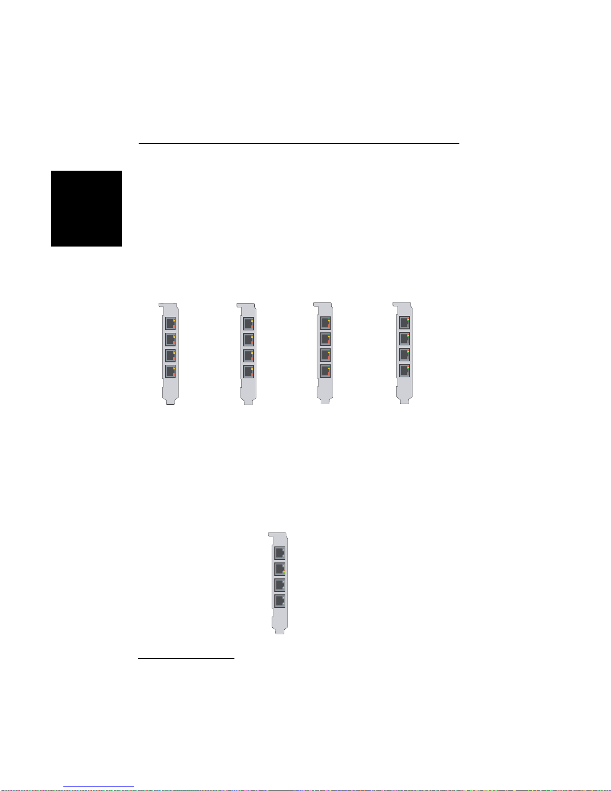
Installation
Note for Dialogic® Diva® V-1PRI PCIe HS, Diva V-2PRI PCIe HS,
ENGLISH
Diva V-4PRI PCIe HS, and Diva V-4PRI PCIe FS Media Boards:
Diva V-xPRI PCIe HS and the Diva V-4PRI PCIe FS Media Boards have four
ports. The "x" or the "4" stand for the activated por ts ; that m ea n s one por t
is activ ated on the Diva V -1PRI HS M edia Board, two ports on the Div a V-2PRI
HS Media Board, and four ports on the Diva V-4PRI PCIe HS and Diva V-4PRI
PCIe FS Media Board. You can use only the activated ports, which are shown
in the graphic below. The diagram is oriented with the edge connector pointing
downwards. Typically, you must specify the port number during software
configuration. Connect the cables as described above.
Diva V-1PRI HS
Media Board
Diva V-2PRI HS
Media Board
Diva V-4PRI HS
Media Board
Diva V-4PRI FS
Media Board
Port 1
Port 1
Port 2
Port 1
Port 2
Port 3
Port 4
Port 1
Port 2
Port 3
Port 4
Note: Diva V-1PRI PCIe HS, V-2PRI PCIe HS, V-4PRI PCIe HS, and V-4PRI
PCIe FS Media Boards do not supply the function of the CSU or DSU internally.
You need to purchase it from an independent distributor.
Diva V-8PRI PCIe FS Med ia Board
Diva V-8PRI PCIe FS Media Boards have four RJ45 ports for connecting four
dongles. The dongles ha ve two ports each for connecti ng two separate PRI
lines; therefore, you can connect to up to eight PRI lines. You can use any
port; typically, you must specify the port number during software
configuration. The port numbers are shown below. The diagram is oriented
with the edge connecto r po inti ng do wnwa rd s .
Port 1 and Port 5
Port 2 and Port 6
Port 3 and Port 7
Port 4 and Port 8
page 28
Page 29
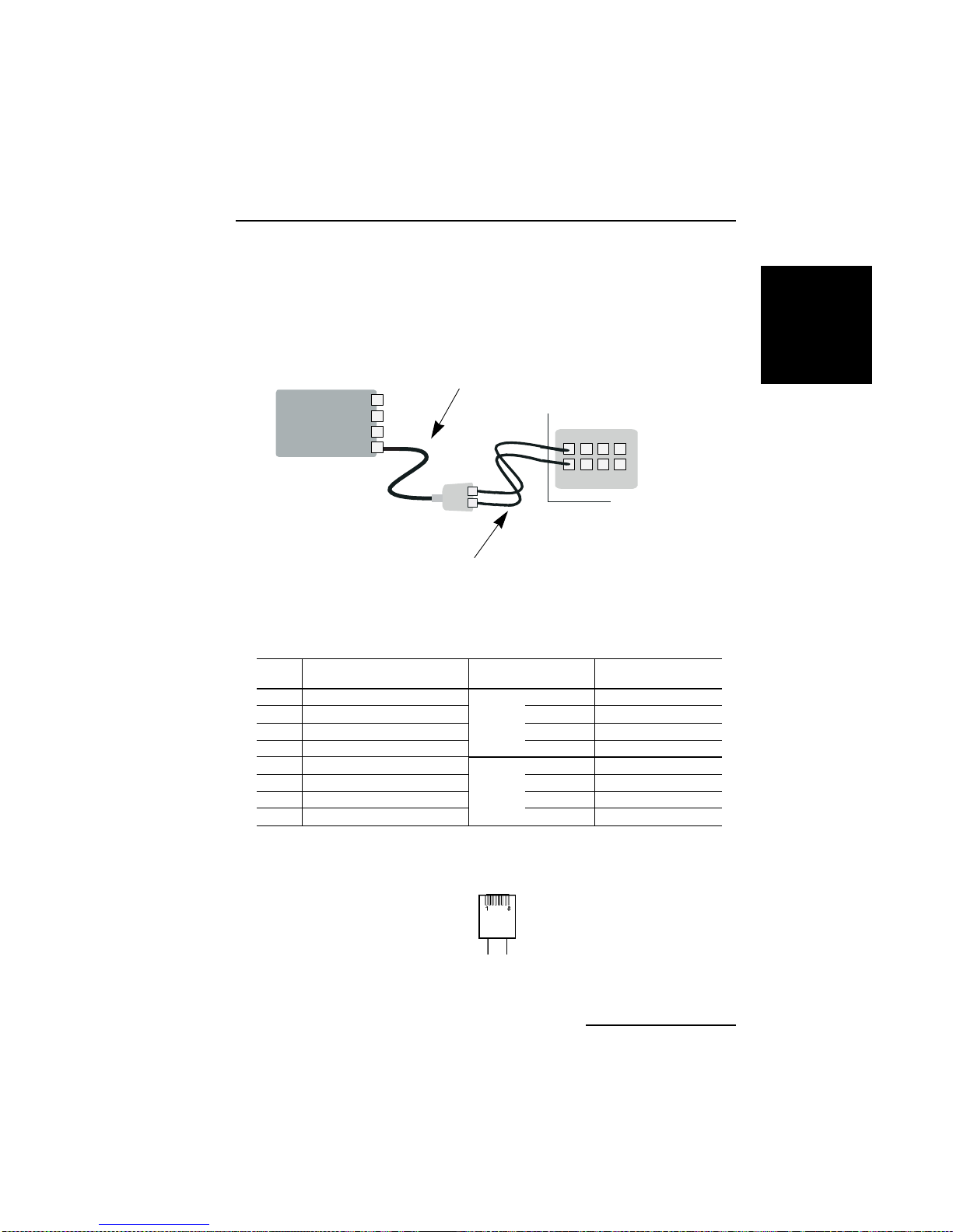
Dialogic® Diva® Media Board Installation Guide
Note: Diva V-8PRI PCIe FS Media Boards do not supply the function of the
CSU or DSU internally. Y ou need to purchase it from an independent distributor .
Connect the Diva V-8PRI PCIe FS Media Board as shown in this
graphic:
1. Take the four cables with the dongle and plug the
RJ45 connectors into the Diva Media Board.
Diva V-8PRI
PCIe FS
Media Board
2. Take the eight cables and plug
the RJ45 connectors into the
dongle. The jack labeled wi th "A"
corresponds to the ports 1,2,3,
and 4. The jack labeled with "B"
corresponds to the ports 5,6,7,
and 8.
Wall jack or PBX
3. Plug the RJ45 connectors
into the wall jack or PBX.
Contact assignments (plugs and jacks):
RJ45 Signals Dongle with RJ45
Pin 1 Receive + (RX +) (Port A)
Pin 2 Receive - (RX -) (Port A) Pin 2 Receive - (RX -)
Pin 3 Receive + (RX +) (Port B) Pin 4 Transmit + (TX +)
Pin 4 Transmit + (TX +) (Port A) Pin 5 Transmit - (TX -)
Pin 5 Transmit - (TX -) (Port A)
Pin 6 Receive - (RX -) (Port B) Pin 2 Receive - (RX -)
Pin 7 Transmit + (TX +) (Port B) Pin 4 Tr ansmit + (TX +)
Pin 8 Transmit - (TX -) (Port B) Pin 5 Transmit - (TX -)
jacks
Pin 1 Receive + (RX +)
Port A
Pin 1 Receive + (RX +)
Port B
Signals
Note: Looking at the RJ45 connectors with the exposed co nnector pins facing
you, the pins are numbered from 1 to 8 from left to right as shown below.
ENGLISH
page 29
Page 30

Installation
If the Dialogic® Diva® PRI Media Board in NT mode is connected to a PBX:
ENGLISH
The Dialogic
®
Diva® System Release software enables you to configure Diva
PRI Media Boards as network termination (NT). This means your Diva Media
Board can serve as an NT for PBXs that act as terminal equipment and
therefore requires an NT to provide a clocking signal. For example, the Diva
Media Board can act as an NT when coupling PBXs with the Q.SIG protocol.
When connecting the Diva Media Board to a PBX that acts as TE, configure
the Diva Media Board as an NT. Wire it to the PBX as shown in the diagram
on page 31 and apply the appropriate assignment to the PBX connectors.
If the ISDN PRI, E1, or T1 line uses open-ended wire connections:
In some cases, you are required to connect to your network termination using
the open-ended connectors. The transmission (TX) leads and the receiving
(RX) leads are identified by color; t ransmission leads are blue and white-blue,
receiving leads are orange and white-orange.
Use an RJ45 to open ends cable:
Dialogic® Diva® PRI
Media Board
Pin 1 Receive + (RX +) white-orange
Pin 2 Receive - (RX -) orange
Pin 4 Transmit + (TX +) white-blue
Pin 5 Transmit - (TX -) blue
shielded plug overall shielded shield
Signals Open Ends
Make sure to connect the tr ansmission leads of you r Diva PRI Media Board to
the receiving connectors of the network termination and the receiving leads
of your Diva PRI Media Board to the transmission connectors of the network
termination.
Note: If the Diva Media Board is not properly connected to the ISDN PRI, E1,
or T1 line, a layer 1 warning light appears on the NT, the Diva Media Board,
the external CSU, an d at the switching cent er of the network provider. The
network provider might then deactivate the line. If this occurs, you must
contact your network provider to reactivate your line.
page 30
Page 31
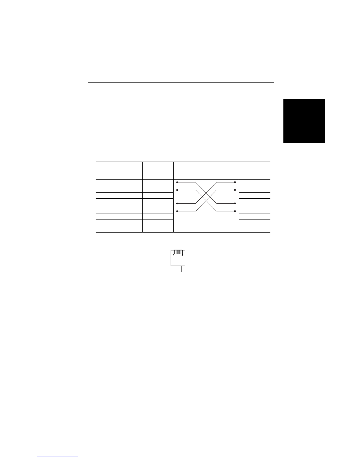
Dialogic® Diva® Media Board Installation Guide
If the Dialogic® Diva® PRI Media Board is run in back - to- ba c k mo de :
The Dialogic
®
Diva® System Release software enables you to configure Diva
PRI Media Boards as network termination (NT). This means you can use two
Diva Media Boards in back-to-back operation.
When using Di va Media Boards back -to- back, conf igure one D iva Medi a Board
as an NT and the other one as TE. Connect the Diva Media Boards with a
crossover cable. You can build your o wn crossover cab le using an open- ended
ISDN cable. Just crimp the open end according to the NT-side assignment
shown in this diagram :
TE Side NT Side
Pins on RJ45 Signals
1 RX + RX +
2RX - RX 3not used
4TX + TX +
5TX - TX -
6not used
7not used
8not used
Wiring
Signals
Note: Looking at the RJ45 connector with the exposed connector pins facing
you, the pins are numbered from 1 to 8 from left to right (as shown below).
ENGLISH
Connect your Dialogic® Diva® Analog Media Board
Use the cables included with the Diva Analog Media Board. How you connect
your Diva Analog Media Board depends on the board type:
®
• To connect any Dialogic
instructions below.
• To connect any Dialogic
instructions on page 33.
• To connect any Dialogic
instructions on page 34.
Important: Use only certified telecommunications cables with No. 26 AWG
(American Wire Gauge) or higher with this equipm ent to ensur e prope r
functioning of the Diva Media Board.
Diva® Analog-2 Media Board, follow the
®
Diva® Analog-4 Media Board, follow the
®
Diva® Analog-8 Media Board, follow the
page 31
Page 32
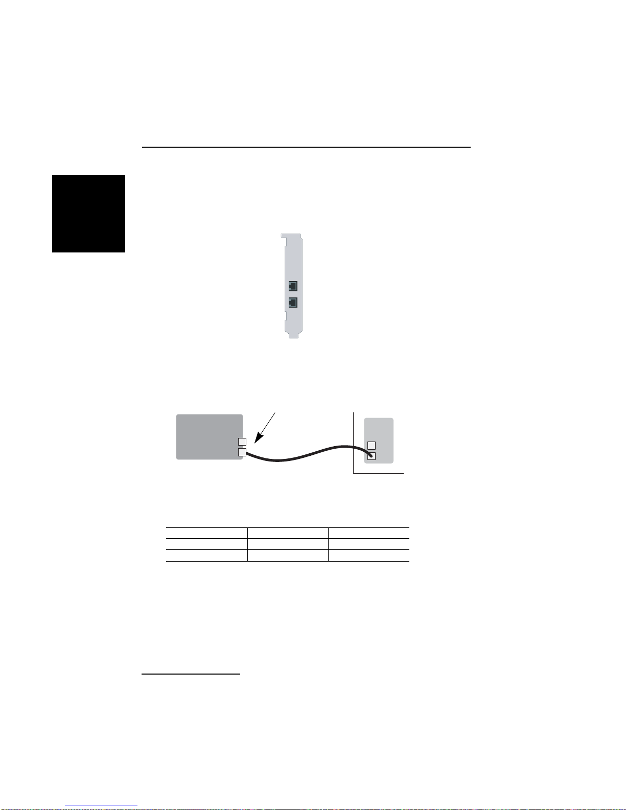
Installation
Dialogic® Diva® Analog-2 Media Boards:
ENGLISH
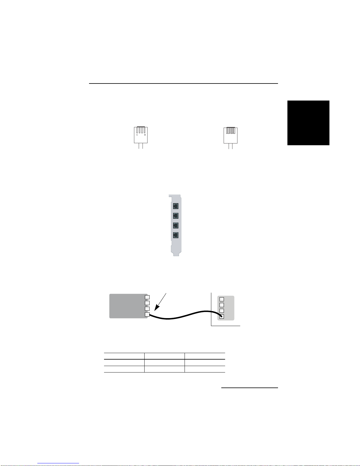
Diva Analog-2 Media Boards have two RJ11 ports for connecting two separate
analog lines. You can use any port; typically, you must specify the port number
during software configuration. The port numbers are shown below. The
diagram is oriented with the edge connector pointing downwards.
Port 1
Port 2
®
Connect your Dialogic
1. Take the two c a ble s included with th e
Diva Media Board and plug the RJ10
connectors into the board.
Diva Analog
Media Board
Diva® Analog-2 Media Board as follows:
Wall jack or PBX
2. Plug the RJ11 connectors into the wall
jack or PBX.
Contact assignments (plugs and jacks):
RJ10 Signals RJ11
Pin 2 Ring Pin 3
Pin 3 Tip Pin 4
Note: Looking at the RJ10 and RJ11 connector with the exposed connector
pins facing yo u, the pins are number ed from 1 to 4 and 1 to 6 from left to
right as shown on the next page.
page 32
Page 33
Dialogic® Diva® Media Board Installation Guide
RJ10 connector RJ11 connector
6
1
Dialogic® Diva® Analog-4 Media Boards:
Diva Analog-4 Media Boards have four RJ11 ports for connecting four separate
analog lines. You can use any port; typically, you must specify the port number
during software configuration. The port numbers are shown below. The
diagram is oriented with the edge connector pointing downwards.
Port 1
Port 2
Port 3
Port 4
Connect your Diva Analog-4 Media Board as follows:
1. Take the four cables included with the Diva
Media Board and plug the RJ10 c onnectors into
the board.
Diva Analo g
Media Board
Wall jack or PBX
ENGLISH
Contact assignments (plugs and jacks):
RJ10 Signals RJ11
Pin 2 Ring Pin 3
Pin 3 Tip Pin 4
2. Plug the RJ11 connectors into the wall
jack or PBX.
page 33
Page 34
Installation
Note: Looking at the RJ10 and RJ11 connector with the exposed connector
ENGLISH
pins facing yo u, the pins are number ed from 1 to 4 and 1 to 6 from left to
right as shown below.
RJ10 connector RJ11 connector
6
1
®
Dialogic
Diva® Analog-8 Media Boards:
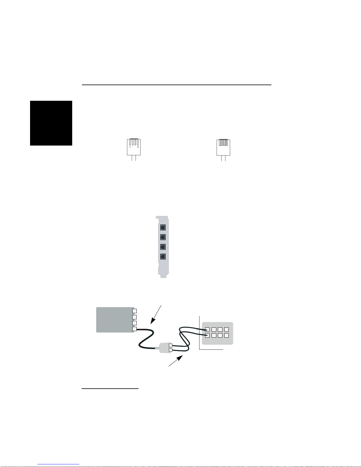
Diva Analog-8 Media Boards have four RJ45 ports for connecting four dongles.
The dongles have two ports each fo r connecting two separate analo g lines;
therefore, you can connect to up to eight analog lines. You can use any port;
typically, you must specify the port number during software configuration. The
port numbers are shown below. The diagram is oriented with the edge
connector pointin g do wnwa rd s.
Port 1 and Port 2
Port 3 and Port 4
Port 5 and Port 6
Port 7 and Port 8
®
Connect your Dialogic
1. Take the four cables with the dongle and plug the
RJ45 connectors into the Diva Media Board.
Diva Analog
Media Board
2. Take the eight cables and
plug the RJ10 connectors into the
dongle. The jack labeled with "A"
corresponds to the ports 1,3,5, and 7.
The jack labeled with "B" corr esponds
to the ports 2,4,6, and 8.
page 34
Diva® Analog-8 Media Board as follows:
Wall jack or PBX
3. Plug the RJ11 connectors
into the wall jack or PBX.
Page 35
Dialogic® Diva® Media Board Installation Guide
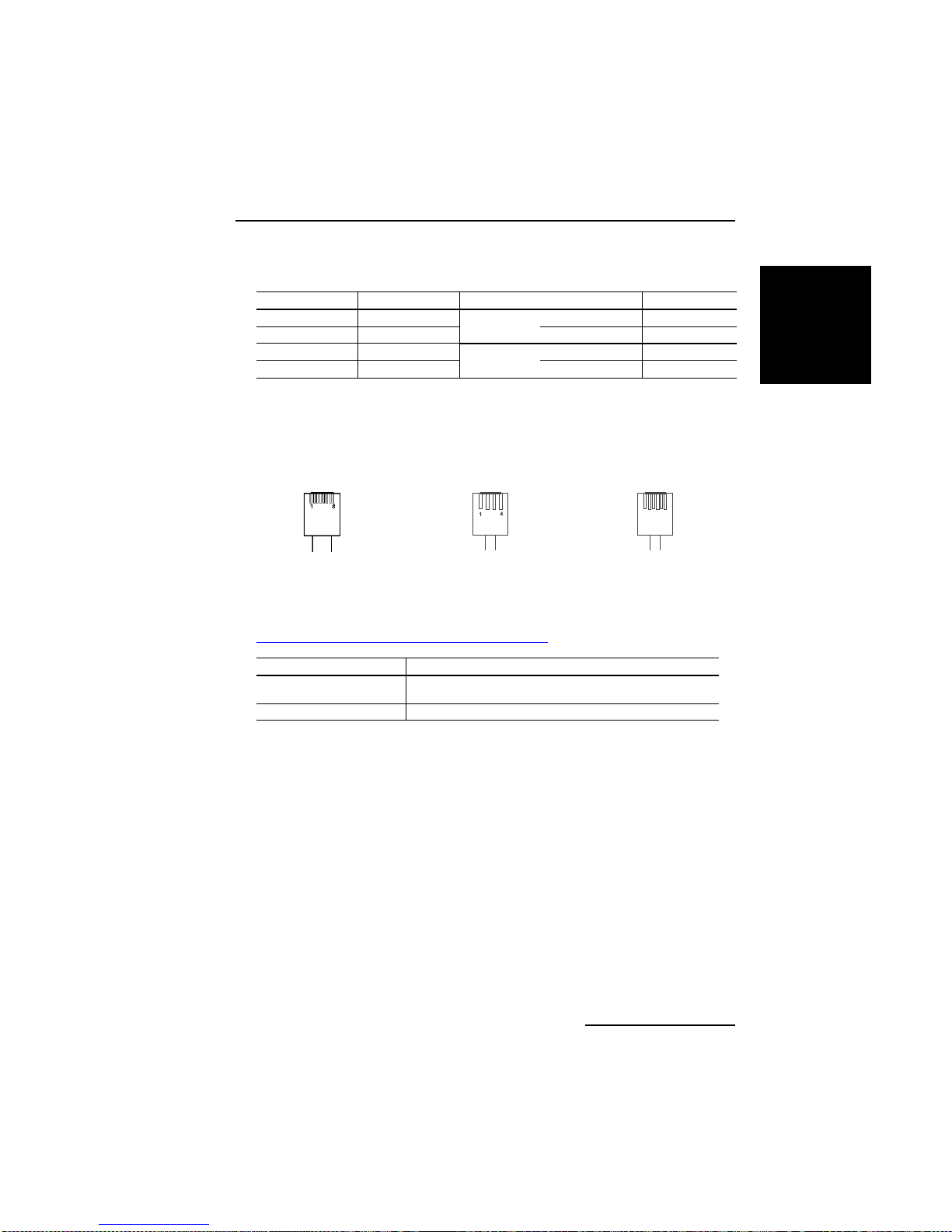
Contact assignments (plugs and jacks):
RJ45 Signals Dongle with RJ10 jacks RJ11
Pin 1 Ring
Pin 2 Tip Pin 3 P in 4
Pin 7 Tip
Pin 8 Ring Pin 2 P in 3
Port A
Port B
Pin 2 Pin 3
Pin 3 Pin 4
Note: Looking at the RJ45, RJ10, and RJ11 connectors with the exp ose d
connector pins facing you, the pins are numbered from 1 to 8, 1 to 4, and 1
to 6 from left to right as shown below.
RJ45 connector RJ10 connector RJ11 connector
6
1
ENGLISH
(C) Install your Dialogic
®
Diva® System Release software
To install the Diva System Release software, see the online documentation
that came with the drivers or that is available on the Dialogic web site at
http://www.dialogic.com/manuals/default.htm
Operating System Reference Guides
All Windows
systems
Linux Dialogic
®
operating
Dialogic® Diva® System Release WIN Reference Guide
®
Diva® System Release LIN Reference Guide
.
page 35
Page 36

Troubleshooting
Troubleshooting
ENGLISH
If you are having problems with your Dialogic® Diva® Media Board or with the
corresponding soft ware, the following suggestio ns can help you try to diagnose
and solve the problems. If these suggestions do not work for you, try the
suggestions described in the online reference guides or in the help files for
the corresponding software, or those on the Dialogic Services & Support web
site (see page 69).
Using the Dialogic® Diva® Line Test tool
Note: The Diva Line Test tool is only available under Microsoft® Windows®
operating systems.
The Diva Line Test tool allows for quickly verifying that your Dialogic
Media Board and the line are working properly.
To open Diva Line Test tool click:
Start > Programs > Dialogic Diva > Line Test.
The Diva Line Test tool offers the following tests:
• Line Check: Performs a quick check of your Dialogic
Release software instal lation and the physical connection.
• Hardware Test: Performs a test only of the controller.
• Phone/Loop : P e rf or ms bas ic in ban d or ou tb an d pho ne tes ts , to v e ri f y t he
connection to other tele p hone s or to itse lf.
• Call Transfer: Performs different call transfer tes ts , wi th th e optio n to
choose the transfer type.
• Fax: Performs basic inbound or outbound fax tests.
For more information about the tests of this tool, see Dialogic
Test Online Help fil e (DS LineTest.chm).
®
Diva® Syste m
®
Diva® Line
®
Diva®
Checking the status LEDs
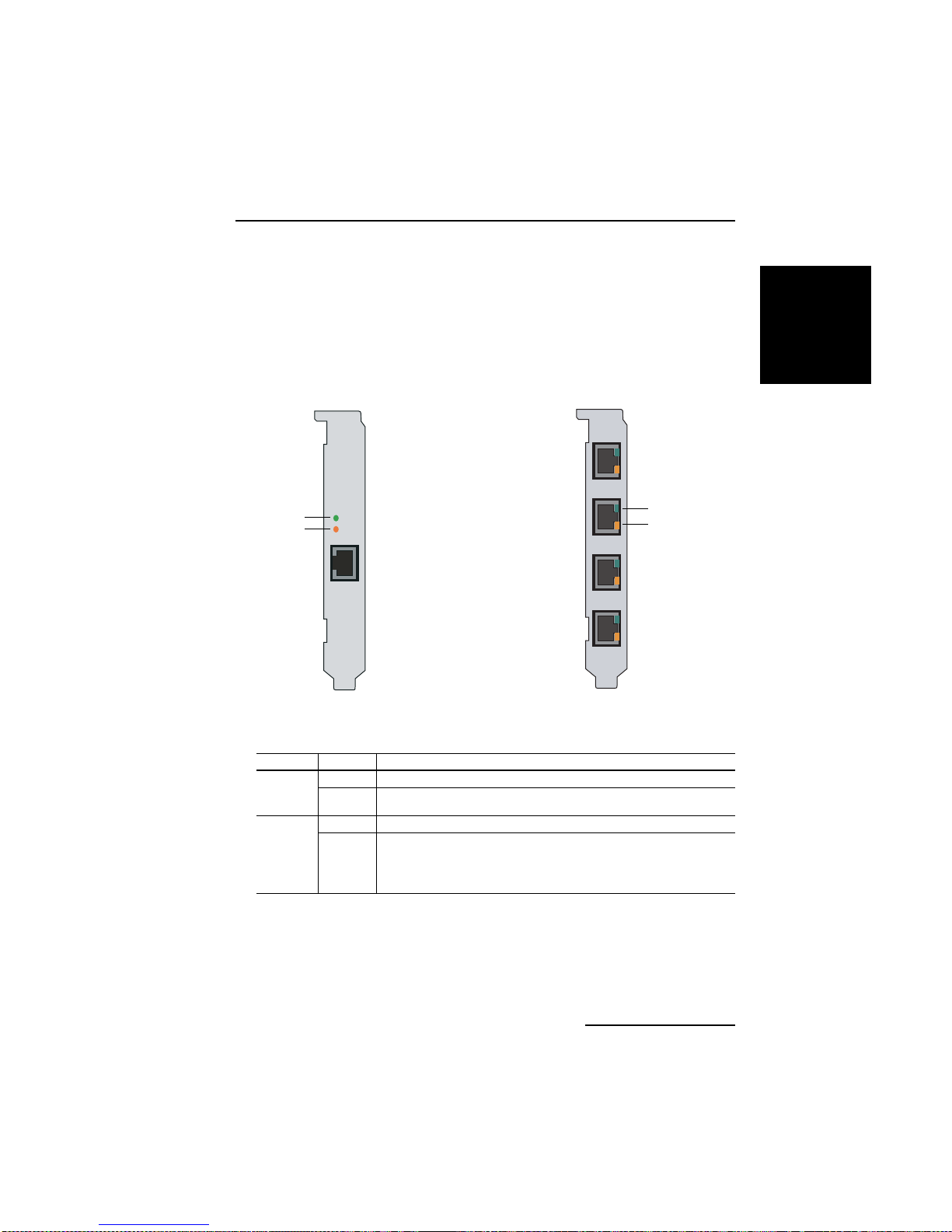
The Dialogic® Diva® BRI and PRI Media Boards have two or four status LEDs
that indicate a specific status of the Diva Media Board.
page 36
Page 37
Dialogic® Diva® Media Board Installation Guide
Dialogic® Diva® BRI and Diva UM-BRI Media Boards
The Di va BRI-CTI, Di va B RI-2FX , Diva B R I- 2, Diva U M-BRI- 2, Diva 4 BRI-8,
and Diva UM-4BRI-8 Media Boards have two LEDs for each port:
Diva BRI-CTI
Diva BRI-2FX
Diva UM-BRI-2
Diva BRI-2
green
orange
The table below describes the function of the LEDs:
Color Status Description
green off Layer 1 is not active.
lit Layer 1 is active. The cabling and the connection to the ISDN work
orange off Layer 2 is not active.
lit Layer 2, i.e. , the D-channel, is active. In Europe, the status of the
properly.
D-channel depends on the switch configuration; the LED might
remain lit for the duration of the call or it might remain lit
continuously. In North America, the D-channel is always active
and, as such, the LED remains lit.
Diva UM-4BRI-8
Diva 4BRI-8
ENGLISH
green
orange
page 37
Page 38
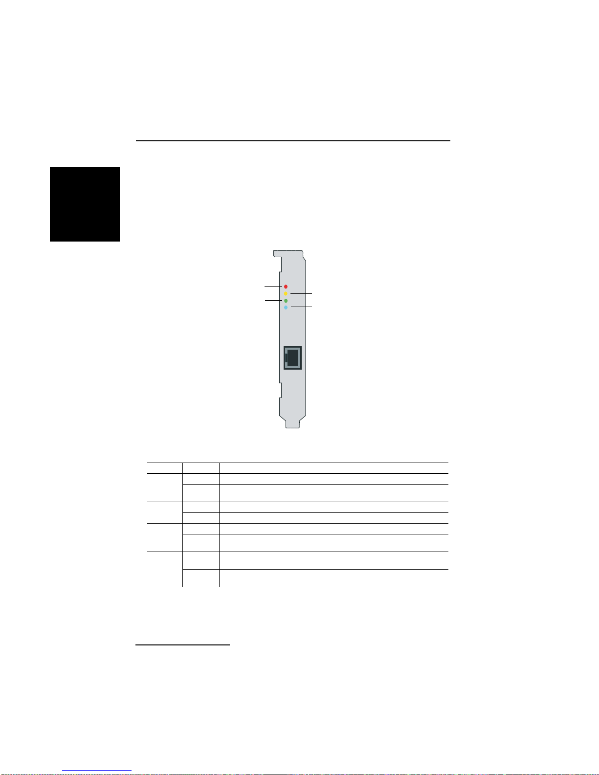
Troubleshooting
Dialogic® Diva® V-PRI, Diva UM-PRI, and Diva PRI Media
ENGLISH
Boards
Diva PRI Media Boards with one port have four LEDs:
Diva V-PRI
Diva UM-PRI
Diva PRI 3.0
red
green
yellow
blue
The table below describes the function of each LED:
Color Status Descript ion
yellow off Normal operation.
lit Remote site is experiencing synchronization problems (if a remote
red off Normal operation.
lit The receiver does not detect a signal (loss of signal/red alarm).
blue off Normal operation.
lit Received frames are not synchronized properly (alarm indication
green off Layer 2 is not active. Check your layer 2 configuration, i.e., swit ch
lit Layer 2 is active. If your Dialogic
alarm/yellow alarm is detected).
signal/blue alarm).
type, switch etc.
properly, layer 2 is always active.
®
Diva® Media Board works
page 38
Page 39
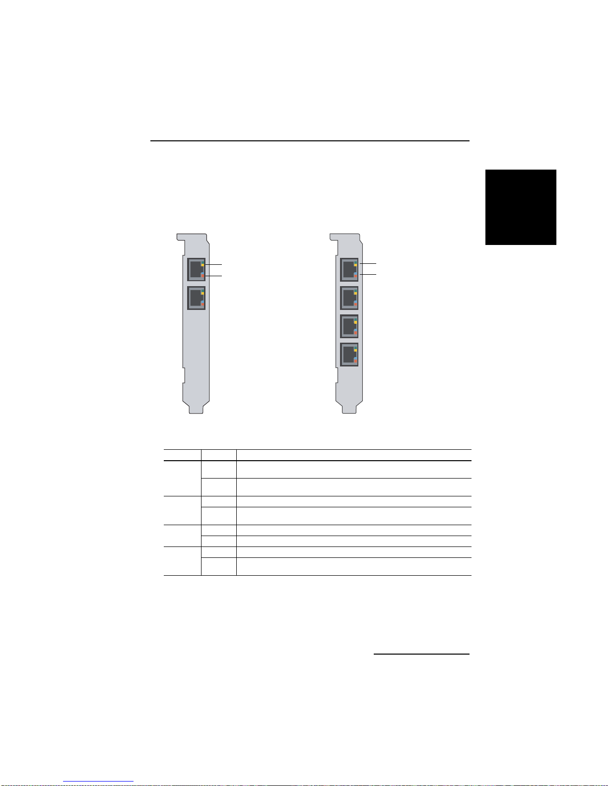
Dialogic® Diva® Media Board Installation Guide
Dialogic® Diva® V-2PRI and V-4PRI Media Boards
Diva V-xPRI PCI Media Boards have two multifunctional LEDs for each port:
Diva V-2PRI Diva V-4PRI
ENGLISH
green or yellow
blue or red
green or yellow
blue or red
The table below describes the function of each LED:
Color Status Description
green off Layer 2 is not active. Check your layer 2 configuration, i.e., switch
lit Layer 2 is active. If your Dialogic
yellow off Normal operation.
lit Remote site is experiencing synchronization problems (if a remote
red off Normal operation.
lit The receiver does not detect a signal (loss of signal/red alarm).
blue off Normal operation.
lit Received frames are not synchronized properly (alarm indication
type, swit ch etc.
properly, layer 2 is always active.
alarm/yellow alarm is detected).
signal/blue alarm).
®
Diva® Media Board works
page 39
Page 40
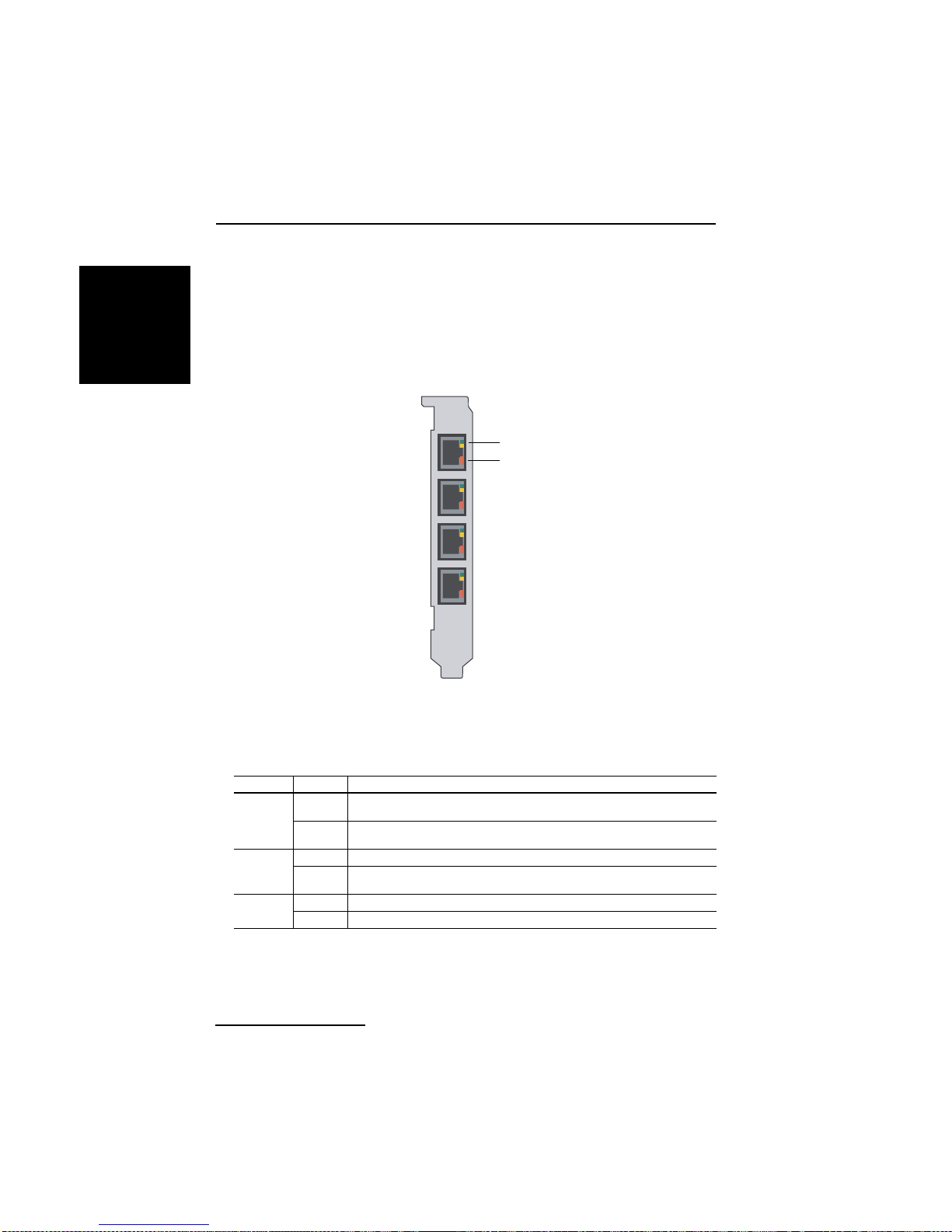
Troubleshooting
Dialogic® Diva® V-1PRI PCIe HS, V-2PRI PCIe HS,
ENGLISH
V-4PRI PCIe HS Media Boards
Diva V-xPRI PCIe HS Media Boards have multifunctional LEDs:
Diva V-1PRI PCIe HS
Diva V-2PRI PCIe HS
Diva V-4PRI PCIe HS
green or yellow
red
Note: On Diva V-1PRI PCIe HS and Diva V-2PRI PCIe HS Media Boards, not
all ports are activated. See the note on page 28 for more information.
The table below describes the function of each LED:
Color Status Description
green off Layer 2 is not active. Check your layer 2 configuration, i.e., switch
lit Layer 2 is active. If your Dialog i c
yellow off Normal operation.
lit Remote site is experie ncing synchronizatio n problems (if a remote
red off Normal operation.
lit The receiver does not detect a signal (loss of signal/red alarm).
page 40
type, switch etc.
properly, layer 2 is always active.
alarm/yellow alarm is detected).
®
Diva® Media Board works
Page 41
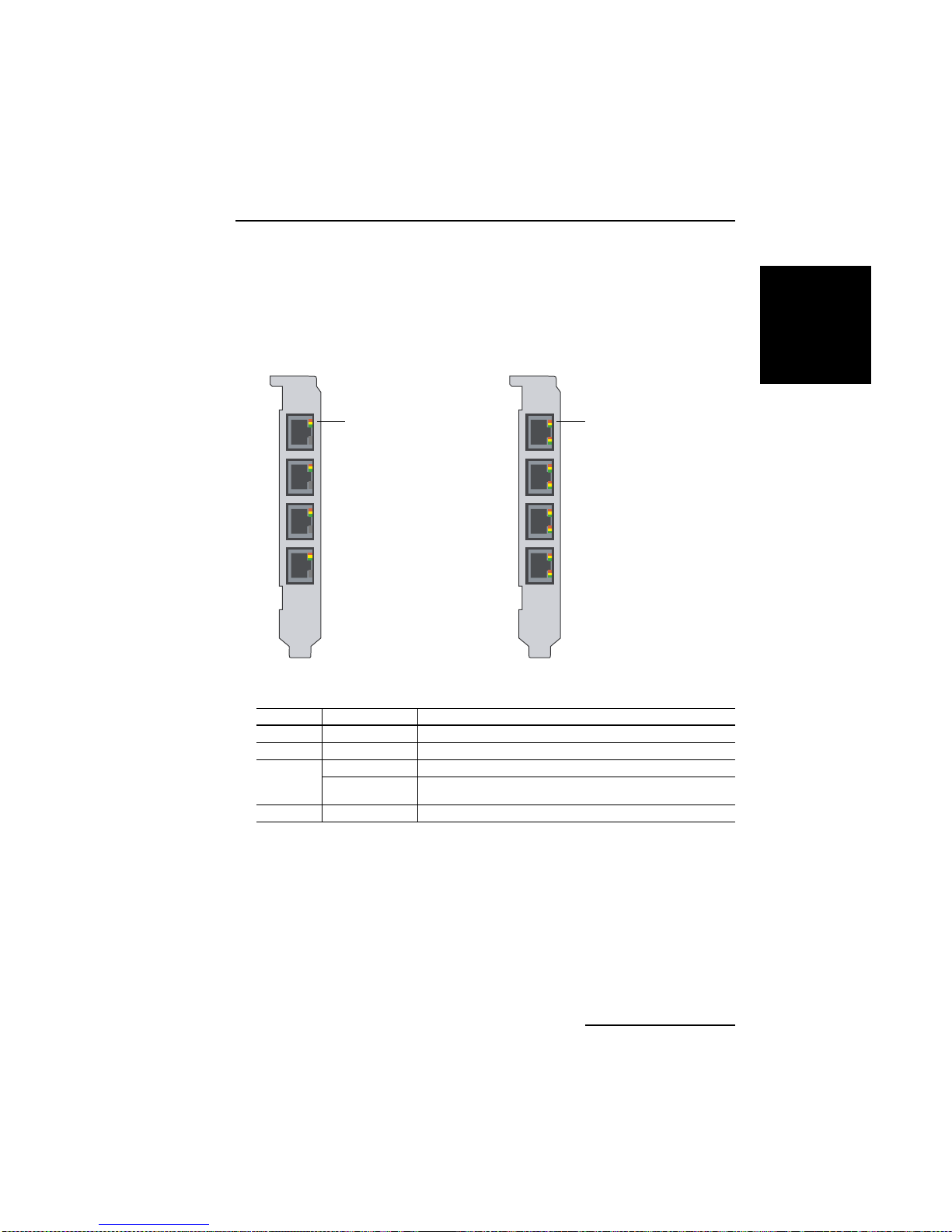
Dialogic® Diva® Media Board Installation Guide
Dialogic® Diva® V-4PRI PCIe FS and V-8PRI PCIe FS
Media Boards
Diva V-xPRI PCIe FS Media Boards have multifunctional LEDs:
Diva V-4PRI PCIe FS Diva V-8PRI PCIe FS
red, yellow, or green red, yellow, or green
The table below describes the function of each LED:
Color Status Description
All colors off Software has not initialized
green lit Carrier Sense (normal error free operation)
yellow lit Yellow alarm
slow flashing
together
red lit Red alarm
Blue alarm
ENGLISH
page 41
Page 42

T echnical Specifications
Technical Specifications
ENGLISH
Environmental requiremen ts:
• Operating temperature: 10 degrees C to 50 degrees C
• Maximum tolerance in voltage fluctuation: according to the respective
specification (PCI/PCIe)
Diva UM-BRI-2
Diva BRI-2
Bus type PCI (3.3/5.0 V)
CPU 32 Bit RISC CPU, 100 MHz
Memory 8 MB SDRAM 16 MB SDRAM
IRQ levels
I/O base addr. (hex)
Shared memory
range
DSPs 2 ADSPs 2185 8 ADSPs 2185
Dimensions in mm
(length x height)
PCB 167.65 x 64.41 174.63 x 106.68
Low profile bracket 181.36 x 80.06
Bracket 180.96 x 120.88 187.84 x 126.37
Data transfer
B-channels 2 x 64 kbps 4 x 2 x 64 kbps
D-channels 1 x 16 kbps 4 x 16 kbps
Plug&Play
Power safe mode
Ports Female RJ45 (ISDN BRI) 4 x Female RJ45 (ISDN BRI)
Physical interfaces ISDN basic rate interface 4 x ISDN basic rate interface
Power requirements 0.33 A @ +5 V typ. 0.58 A @ +5 V typ.
Allocated by PC BIOS
8 MB 16 MB
yes
Diva UM-4BRI-8
Diva 4BRI-8
page 42
Page 43

Dialogic® Diva® Media Board Installation Guide
Diva UM-BRI-2 PCIe
Diva BRI-2 PCIe
Bus type PCIe 1.0a x1 lane
CPU 32 Bit RISC CPU, 100 MHz
Memory 64 MB SDRAM
IRQ levels
I/O base addr. (hex)
Shared memory
range
DSPs 2 ADSPs 2185 8 ADSPs 2185
Dimensions in mm
(length x height)
PCB 167.65 x 68.90 167.65 x 111.15
Low profile bracket 181.36 x 80.06
Bracket 180.96 x 120.88 180.96 x 126.31
Data transfer in kbps
B-channels 2 x 64 kbps 4 x 2 x 64 kbps
D-channels 1 x 16 kbps 4 x 16 kbps
Plug&Play
Power safe mode
Ports Female RJ45 (ISDN BRI) 4 x Female RJ45 (ISDN BRI)
Physical interfaces I SDN basic rate interface 4 x ISDN basic rate interface
Power requirements 0.27 A @ 3.3 V typ.
0.17 A @ 12 V typ.
Allocated by PC BIOS
8 MB 16 MB
Diva UM-4BRI-8 PCIe
Diva 4BRI-8 PCIe
yes
0.42 A @ 3.3 V typ.
0.19 A @ 12 V typ.
ENGLISH
page 43
Page 44

T echnical Specifications
Diva BRI-CTI
ENGLISH
Bus type PC I (3 .3/5.0 V)
CPU 32 Bit RISC CPU, 133 MHz
Memory 8 MB SDRAM
IRQ levels
I/O base addr. (hex)
Shared memory range 8 MB
DSPs none
Dimensions in mm
(length x height)
PCB 167.65 x 64.41
Low profile bracket 181.36 x 80.06
Bracket 180.96 x 120.88
Data transfer in kbps
B-channels 2 x 64 kbps
D-channel 1 x 64 kbps
Plug&Play
Power safe mode
Port Female RJ45 (ISDN BRI)
Physical interface ISDN basic rate interface
Power requirements 0.3 A @ +5 V typ.
Diva BRI-2FX
Allocated by PC BIOS
yes
page 44
Page 45

Dialogic® Diva® Media Board Installation Guide
Diva V-PRI
Diva UM-PRI
Diva PRI 3.0
Bus type PCI (3.3/5.0 V)
CPU 32 Bit RISC CPU, 300 MHz
Memory 64 MB SDRAM
IRQ levels
I/O base addr. (hex)
Shared memory range 8 MB
DSPs either 2, 10, 24, or 31 ADSPs 2185
Dimensions in mm PRI/E1/T1-CTI, PRI/E1/T1-8:
PCB 174.63 x 106.68
Bracket 187.84 x 126.37
Dimensions in mm
(length x height)
PCB 312.00 x 106.68
Bracket without retainer 325.31 x 126.37
Bracket and retainer 352.17 x 126.37
Data transfer in kbps
B-channels 23 or 30 x 64 kbps
D-channel (PRI) 1 x 64 kbps
Channelized T1 1 x 56 kbps
Plug&Play
Power sa f e mode
Port Female RJ-45 (ISDN PRI)
Physical interface ISDN primary rate interface
Power requirements PRI/E1/T1-CTI:
Allocated by PC BIOS
PRI/E1-30, V-PRI:
yes
0.58 A @ +5 V typ.
1.70 A @ +5 V max.
PRI/E1/T1-8:
0.65 A @ +5 V typ.
2.00 A @ +5 V max.
PRI/T1-24, PRI/E1-30, V-PRI:
0.97 A @ +5 V typ.
2.70 A @ +5 V max.
ENGLISH
page 45
Page 46

T echnical Specifications
Diva V-PRI PCIe
ENGLISH
Bus type PCIe 1.0a x1 lane
CPU 32 Bit RISC CPU, 300 MHz
Memory 64 MB SDRAM
IRQ levels
I/O base addr. (hex)
Shared memory range 8 MB
DSPs either 2, 24, or 31 ADSPs 2185
Dimensions in mm
(length x height)
PCB 167.65 x 68.90
Low profile bracket 181.38 x 80.06
Bracket 180.96 x 120.88
Dimensions in mm PRI/T1-24 PCIe, PRI/E1-30 PCIe, V-PRI PCIe:
PCB 312.00 x 111.15
Bracket without retainer 325.31 x 126.31
Bracket and retainer 352.17 x 126.31
Data transfer in kbps
B-channels 23 or 30 x 64 kbps
D-channel (PRI) 1 x 64 kbps
Channelized T1 24 x 56 kbps
Plug&Play
Power safe mode
Port Female RJ45 (ISDN PRI)
Physical interface Primary rate interface or channelized T1 interface
Power requirements PRI/E1/T1-CTI PCIe:
Diva UM-PRI PCIe
Diva PRI PCIe
Allocated by PC BIOS
PRI/E1/T1-C T I P CIe:
yes
0.96 A @ +3.3 V typ.
0.04 A @ +12 V typ.
PRI/T1-24 PCIe, V-PRI/T1-24 PCIe:
2.1 A @ +3.3 V typ.
0.03 A @ +12 V typ.
PRI/E1-30 PCIe, V-PRI/E1-30 PCIe:
2.3 A @ +3.3 V typ.
0.03 A @ +12 V typ.
page 46
Page 47

Dialogic® Diva® Media Board Installation Guide
Diva V-2PRI Diva V -4PRI
Bus type PCI (3.3/5.0 V)
CPU 64 Bit RISC CPU, 466 MHz
Memory 64 MB SDRAM
IRQ levels
I/O base addr. (hex)
Shared memory range 8 MB
DSPs 10 ADSPs-BF533
Dimensions in mm
(length x height)
PCB 312.00 x 106.68
Bracket without
retainer
Bracket and retainer 352.17 x 126.37
Data transfer in kbps
B-channels 2 x 23 x 64 kbps
D-channels (PRI) 2 x 64 kbps 4 x 64 kbps
Channelized T1 2 x 24 x 56 kbps 4 x 24 x 56 kbps
Plug&Play
Power sa f e mode
Ports 2 x Female RJ45 (ISDN PRI) 4 x Female RJ45 (ISDN PRI)
Physical interfaces 2 x ISDN primary rate interface
Power requirements 3.0 A @ +3.3 V typ.
(32 MB SDRAM)
2 x 30 x 64 kbps
or 2 x channelized T1 interface
4.9 A @ +3.3 V max.
0.02 A @ +5 V typ.
0.04 A @ +5 V max.
Allocated by PC BIOS
325.31 x 126.37
or
20 ADSPs-BF533
(32 MB SDRAM)
4 x 23 x 64 kbps
or
4 x 30 x 64 kbps
yes
4 x ISDN prima ry rate inter face
or 4 x channelized T1 interface
5.5 A @ +3.3 V typ.
6.5 A @ +3.3 V max.
0.04 A @ +5 V typ.
0.08 A @ +5 V max.
ENGLISH
page 47
Page 48

T echnical Specifications
Diva V-1PRI
ENGLISH
Bus type PCIe 1.0a x1 lane
CPU 64 Bit RISC CPU, 466 MHz
Memory 64 MB SDRAM
IRQ levels
I/O base addr . (hex)
Shared memory
range
DSPs 12 ADSPs-BF533 (32 MB SDRAM)
Dimensions in mm
(length x height)
PCB 167.65 x 111.15
With bracket 180.96 x 126.31
Data transfer
B-channels 1 x 23 x 64 kbps
D-channels (PRI) 1 x 64 kbps 2 x 64 kbps 4 x 64 kbps
Channelized T1 1 x 24 x 56 kbps 2 x 24 x 56 kbps 4 x 24 x 56 kbps
Plug&Play
Power safe mode
Ports 1 x Female RJ45
Physical interfaces 1 x ISDN primary rate
Power requirements 0.91 A @ 3.3 V max.
PCIe HS
or
1 x 30 x 64 kbps
(ISDN PRI)
interface or
1 x channelized T1
interface
Diva V-2PRI
PCIe HS
Allocated by PC BIOS
8 MB
2 x 23 x 64 kbps
or
2 x 30 x 64 kbps
yes
2 x Female RJ45
(ISDN PRI)
2 x ISDN primary
rate interface or
2 x channelized T1
interface
1.00 A @ 12 V max.
Diva V-4PRI
PCIe HS
4 x 23 x 64 kbps
or
4 x 30 x 64 kbps
4 x Female RJ45
(ISDN PRI)
4 x ISDN primary rate
interface or
4 x channelized T1
interface
page 48
Page 49

Dialogic® Diva® Media Board Installation Guide
Diva V-4PRI PCIe FS Diva V-8PRI PCIe FS
Bus type PCIe 1.0a x4 lane
CPU 64 Bit RISC CPU, 466 MHz
Memory 128 MB DDR2-SDRAM
IRQ levels
I/O base addr . (hex)
Shared memory
range
DSPs 24 ADSPs-BF533 (32 MB SDRAM)
Dimensions in mm
(length x height)
PCB 312.00 x 111.15
Bracket without
retainer
Bracket and
retainer
Data transfer
B-channels 4 x 23 x 64 kbps
4 x 30 x 64 kbps
D-channels (PRI) 4 x 64 kbps 8 x 64 kbps
Channelized T1 4 x 24 x 56 kbps 8 x 24 x 56 kbps
Plug&Play
Power sa f e mode
Ports 4 x Female RJ45 (ISDN PRI) 8 x Female RJ45 (ISDN PRI)
Physical interfaces 4 x ISDN primary rate interface
4 x channelized T1 interface
Power requirements 1.8 A @ 3.3 V typ.
Allocated by PC BIOS
325.31 x 126.31
352.17 x 126.31
or
or
1.5 A @ 12 V typ.
8 MB
8 x 23 x 64 kbps
or
8 x 30 x 64 kbps
yes
8 x ISDN primary r at e inte rfac e
8 x channelized T1 interface
or
ENGLISH
page 49
Page 50

T echnical Specifications
Diva UM-Analog-2
ENGLISH
Bus type PCI (3.3/5 .0 V)
CPU 32 Bit RISC CPU, 100 MHz
Memory 16 MB SDRAM
IRQ levels
I/O base addr. (hex)
Shared memory range 16 MB
DSPs either 2, 4, or 8 ADSPs 2185 according to model
Dimensions in mm
(length x height)
PCB 167.65 x 64.41 312.00 x 106.68
Low profile bracket 181.36 x 80.06
Bracket 180.96 x 120.88
Bracket without
retainer
Bracket and retainer 352.17 x 126.37
Data transfer max. 2, 4, or 8 x 56 kbps according to model
Plug&Play
Power safe mode
Ports 2 RJ11 jacks Analog-4: 4 RJ11 jacks
Physical interfaces 2, 4, or 8 x analog interface V.90 according to model
Power requirements 0.34 A @ +5 V typ. Analog-4:
Diva Analog-2
Allocated by PC BIOS
Diva UM-Analog-4
Diva UM-Analog-8
Diva Analog-4
Diva Analog-8
325.31 x 126.37
yes
Analog-8: 4 RJ45 jacks
0.45 A @ +5 V typ.
Analog-8:
0.5 A @ +5 V typ.
page 50
Page 51

Dialogic® Diva® Media Board Installation Guide
Diva UM-Analog-2 PCIe
Diva Analog-2 PCIe
Bus type PCIe 1.0a x1 lane
CPU 32 Bit RISC CPU, 100 MHz
Memory 16 MB SDRAM
IRQ levels
I/O base addr. (hex)
Shared memory range 1 6 MB
DSPs either 2, 4, or 8 ADSPs 2185 according to model
Dimensions in mm
(length x height)
PCB 167.65 x 68.90 167.65 x 111.15
Low profile bracket 181.38 x 80.06
Bracket 180.96 x 120.88 180.96 x 126.31
Data transfer in kbps max. 2, 4, or 8 x 56 kbps according to model
Plug&Play
Power sa f e mode
Ports 2 RJ11 jacks Analog-4: 4 RJ11 jacks
Physical interfaces 2, 4, or 8 x analog interface V.90 according to model
Power requirements 0.26 A @ 3.3 V typ.
0.16 A @ 12 V typ.
Allocated by PC BIOS
Diva UM-Analog-4 PCIe
Diva UM-Analog-8 PCIe
Diva Analog-4 PCIe
Diva Analog-8 PCIe
yes
Analog-8: 4 RJ45 jacks
Analog-4:
0.26 A @ 3.3 V typ.
0.18 A @ 12 V typ.
Analog-8:
0.34 A @ 3.3 V typ.
0.22 A @ 12 V typ.
ENGLISH
page 51
Page 52
International Regulatory Information
International Re gu la to r y Inf orm at io n
ENGLISH
Regulatory information for the USA
WARNING: Changes or modifications to this unit not expressly approved
by Dialogic Corporation could void the user's authority to
operate the equipment.
FCC Declaration of Conformity
We:
Dialogic
1515 Route 10
Parsippany
NJ 07054
Te l: (97 3 ) 967 -60 00
Declare under our so le lega l re sponsibility that the produ ct s liste d be lo w to
which this declaration relates, are in conformity with Part 15 of the FCC Rules.
Operation is subject to the following two conditions:
(1) This device may not cause harmful interference, and
(2) this device mu st acce pt an y int er fere nc e rece i v ed, incl u ding i nte rf ere nce
that may cause undesired operation.
Note: This equipment has been tested and found to comply with the limits
for a Class B digital device, pursuant to Part 15 of the FCC Rules. These limits
are designed to provide r easonable protection against harmful i nterference in
a residential installation. Thi s equipment generat es, uses and can radi ate radio
frequency energy and, if not installed and used in accordance with the
instructions , ma y cause harmful inte rference to radio communications .
However, there is no guarantee that interference will not occur in a particular
installation. If this equipment does cause harmful interference to radio or
television recep tion, which can be det ermined by turning the equi pm e n t off
and on, the user is encouraged to try to co rr e ct the inte rf e re nc e by one or
more of the follo wing measures:
• Reorient or reloca te the rec e iv ing a n ten na.
• Increase the separation between the equipment and receiver.
• Connect the equipment in to an outlet on a circuit different from that to
which the receiver is connected.
• Consult the dealer or an experi enced radio/TV tech nician for help.
page 52
Page 53

Dialogic® Diva® Media Board Installation Guide
FCC Part 68 Notice
This equipment complies with Part 68 of the FCC rules and the requirements
adopted by the ACTA. On the bottom of this equipment is a label that contains,
among other inform a tio n, a FCC pa rt 68 re g ist ration num be r or a prod uc t
identifier in the format US: AAAEQ##TXXXX. If requested, this information
must be provided to the telephone company .
A plug and jack used to connect this equipment to the premises wiring and
telephone network must comply with the applicable FCC part 68 rules and
requirements adopted by the ACTA. A compliant telephone cord and modular
plug is provided with this product. It is designed to be connected to a
compatible modular jack that is also compliant.
The REN is used to determine the number of devices that may be connected
to a telephone line . Exce ss ive RE N s on a tel ep hone line may result in the
devices not rin ging in response t o an inco ming call . In mos t but not all ar eas,
the sum of RENs should not exceed five (5.0). T o be certain of the number of
devices that may be connecte d to a line , as de te rm in ed by the total REN s ,
contact the local telephone company.
If this equipment causes harm to the telephone network, the telephone
company will notify you in advance that temporary discontinuance of service
may be required. But if advance notice is not practical, the telephone company
will notify the cu sto mer as soon as pos si ble .
Also, you will be advised of your right to file a complaint with the FCC if you
believe it is necessary.
The telephone company may make changes in its facilities, equipment,
operations, or procedures that could af fect the oper ation of the equipment . If
this happens, the telephone company will provide advance notice in order for
you to make the necessary modifications in order to maintain uninterrupted
service.
If trouble is ex perienced wit h this equipmen t, please contact us for repair and
warranty information. If the trouble is causing harm to the telephone network,
the telephone company may request you to remove the equipment from the
network until th e pr ob le m is re so lve d.
Dialogic
1515 Route 10
Parsippany
NJ 07054
Te l: (97 3) 967-6000
This unit contains no user-serviceable parts.
Connection to party lines is subject to state tariffs. Contact the state public
utility commission, public service commission or corporation commission for
information.
ENGLISH
page 53
Page 54

International Regulatory Information
The mounting of the approved products in the final assembly must be made
ENGLISH
so that the approved products are isolated from exposure to any hazardous
voltages within the assembly. Adequate separation and restraint of cables and
cords must be prov ided. The final ass e m ble r sha ll pr ovi d e in th e co ns u m er
instructions all applicable customer information.
The Telephone Consumer Protection Act of 1991 makes it unlawful for any
person to use a computer or other electronic device to send any message via
a telephone fax machine unless such message cl early contains in a margin at
the top or bottom of each transmitted page or on the first page of the
transmission, the date and time it is sent and an identification of the business
or other entity, or other individual sending the message and the telephone
number of the sending machine or such business, other entity, or individual.
The telephone number provided may not be a 900 number or any other
number for which charges exce ed local or long-distance transmi ssion charges.
It is the responsibi lity of the e nd us er or de vel oper to ensure that the
regulations set forth in the preceding paragraph are followed. Application
developers must pr ovide support for fax branding in the applicatio n s the y
develop and inform u s er s of their responsibili ty under the Act along wit h
instructions for use. Developers can find instructions for setting up a fax
header in the Dialogic software reference manual. End users should consult
the documentation that is provided with their computer telephony application
for instructions on fax branding identification.
®
Dialogic
Without Fax
option
With Fax option 02IS5 XD 6.0 P N/A
Diva® Basic Rate Interface (BRI) Media Boards:
Facility
Interface
code
02IS5 XD 6.0N N/A
Digital Reg.
code
Service Order
code
USOC Jack
Type
Dialogic
Facility Interface
page 54
®
Diva® Primary Rate Inter face (PRI) Media Boards:
code
04DU9-1SN
04DU9-BN
04DU9-DN
04DU9-1KN
04DU9-1SN
04DU9-BN
04DU9-DN
04DU9-1KN
Digital Reg. code Service Order
DD 6.0F RJ48-C
XD 6.0N RJ48-C
code
USOC Jack Type
Page 55

Dialogic® Diva® Media Board Installation Guide
Dialogic® Diva® Analog Media Boards:
REN USOC Ja ck Type
Diva Analog-2
Diva Analog-4
Diva Analog-8
Diva UM-Analog-2
Diva UM-Analog-4
Diva UM-Analog-8
Diva Analog-2 PCIe
Diva Analog-4 PCIe
Diva Analog-8 PCIe
Diva UM-Analog-2 PCIe
Diva UM-Analog-4 PCIe
Diva UM-Analog-8 PCIe
0.2B RJ11-C
0.1B RJ11-C
Regulatory information for Canada
NOTICE: This product meets the applicable Industry Canada technical
specifications.
Le présent matériel est conforme aux specifications techniques applicables
d'Industrie Canada.
This Class B digital apparatus complies with Canadian ICES-003.
Cet appareil numérique de la classe B est conforme à la norme NMB-003 du
Canada.
®
Dialogic
Dialogic
Dialogic
Diva® Analog Media Boards
®
Diva® Analog PCI Media Boards have a REN of 0.2.
®
Diva® Analog PCIe Media Boards have a REN of 0.1.
ENGLISH
Regulatory informatio n fo r Europe
COMPLIANCE
To receive detailed approval information, go to
http://www.dialogic.com/declarations
All Dialogic
®
Diva® Media Boards are certified in Europe ( mark) and North
America (FCC and Industry Canada).
Approval in Europe includes only countries that accept European Union
approval ( mark): Austria, Belgium, Cyprus, Czech Republic, Denmark,
Estonia, Finland, France, Germany, Greece, Hungary, Iceland, Ireland, Italy,
Latvia, Lithuania, Luxembourg, Malta, Netherlands, Norway, Poland, Portugal,
Slovakia, Slovenia, Spain, Sweden, Switzerland, and United Kingdom.
.
page 55
Page 56

International Regulatory Information
Some other countries in Eastern Europe and the Mediterranean region also
ENGLISH
accept the CE-mark. If you are unsure, please check with your equipment
supplier, service provider or regulatory authority for confirmation.
®
The Dialogic
products covered by this notice meet the fol low ing Europ e an
Directives:
2006/95/EC Safety/Low Voltage Directive
2004/108/EC EMC Directive
1999/5/EC R&TTE Directive
2011/65/EU RoHS Directive
To achieve CE compliance, be sure to select a host that already meets the
EMC and Low Voltage Directives before the addition of any optional board.
Remember that the use of option boards declared compliant with the Directi ves
by their manufacturer only gives "presumption of compliance" for the whole
system. It is the responsibility of the system supplier to verify that the
requirements of th e listed Directives are still met by the final system, as
supplied to the end-user. System integrators should take notice of further
conditions expressed in this section and th e Sa fety section.
Dialogic
®
Diva® BRI Media Boards
The products covered by thi s notice have been successfully tested against TBR
3 basic call contro l. Ap pl ic a tio n deve lo pe rs im ple m e n tin g su p pl em e n tar y
services at application level must ensure that their implementation complies
with the services off e re d by the loc a l Pu b lic Switc he d Telephone Network
(PSTN) operator . In case of doubt, network specifications must be consulted;
the R&TTE Directive imposes that each PSTN operator makes such
specifications available.
Inter-working is guarant ee d on ly wi th P ubl ic Switc he d Telephone Networks
(PSTNs) offering Basic Rate Access conforming to EuroISDN specifications.
Before any connection to PSTN offering other Basic Rate Access to other
national or international BRI standards, please consult your Dialogic
representative for standards other than EuroISDN.
page 56
Page 57

Dialogic® Diva® Media Board Installation Guide
Dialogic® Diva® PRI Media Boards
The products covered by thi s notice have been successfully t ested against TBR
4 basic call cont ro l. Ap pl ic a tio n de velo pe rs im plementing su pp le me ntary
services at application level must ensure that their implementation complies
with the services off e re d by the loc a l Pu b lic Switc he d Telephone Network
(PSTN) operator . In case of doubt, network specifications must be consulted;
the R&TTE Directive imposes that each PSTN operator makes such
specifications available.
Inter-working is guaranteed only with Public Switched Telephone Networks
(PSTNs) offering Primar y Rate Acc ess conformin g to EuroISDN speci ficati ons.
Before any connecti on to PSTN offer ing Primary R ate Access to other national
or international E1 standa rds, please consult your Dialogic representative.
®
Dialogic
Diva® Analog Media Bo ards
This equipment has been te sted agains t TBR 21 re quiremen ts (January 1998
edition - Terminal Equipment (TE) capable of 2-wire access to an analogue
Public Switched Telephone Network (PSTN), that is capable of originating a
circuit-switched call using Dual Tone Multi Frequency (DTMF) signaling and/or
receiving an incoming circuit-switched call).
Due to difference s among the indivi dual PSTNs provided in different cou ntries,
compliance to TBR 21 does not, of itself, give an unconditional assurance of
successful ope ration on eve ry PS TN netw ork termination poin t .
In the event of problems, you should first contact your equipment supplier.
Conditions for TBR3, TBR4, and TB R 21 Compliance
To comply with the TBRs, be sure to adhe r e to the fol low ing req uir e me nt s:
• The appropriate parameter file must be instal led on the system and enabled
on these products. To enable it under Windows
®
, see below . For Linux, see
page 59.
ENGLISH
page 57
Page 58
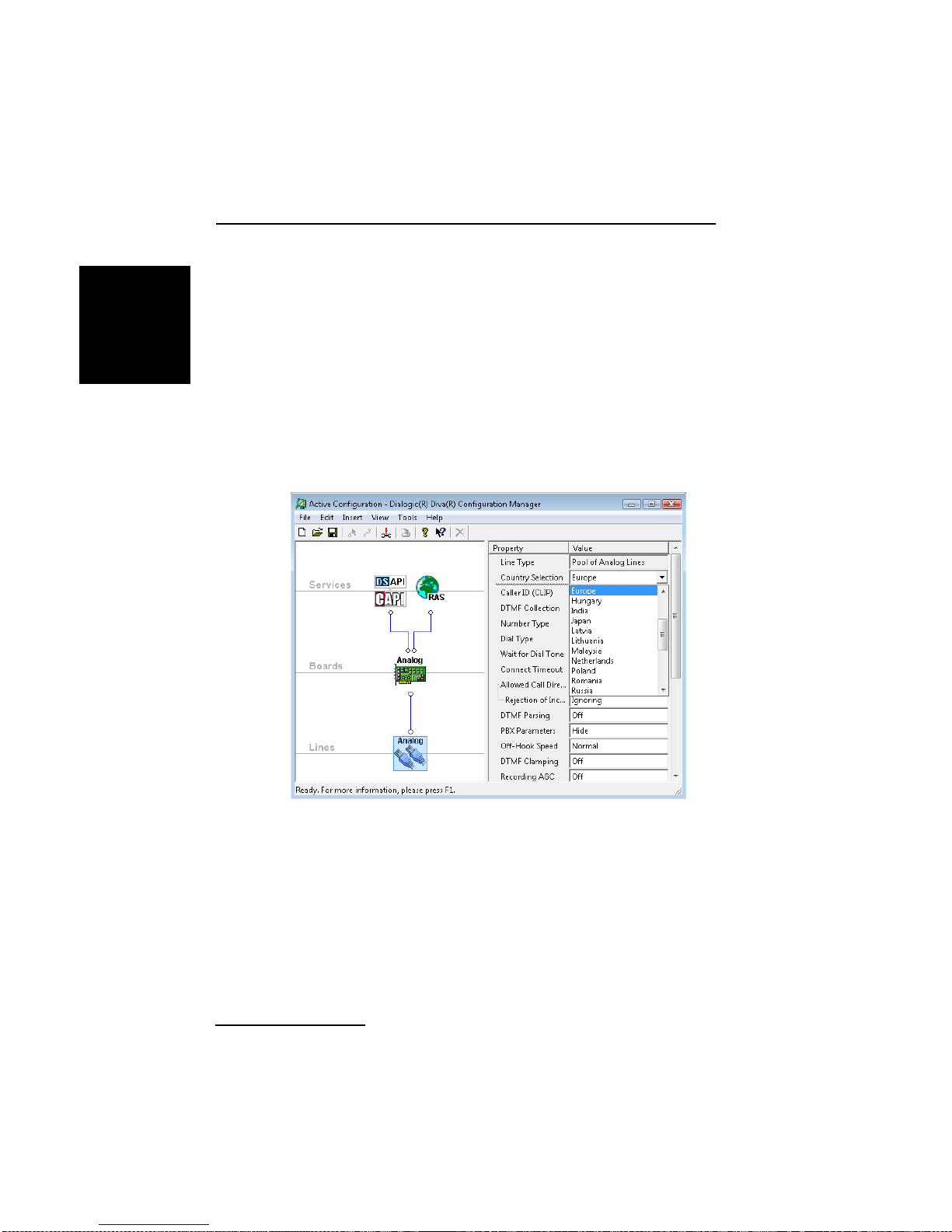
International Regulatory Information
Under Windows®:
ENGLISH
1. Click Start > Programs > Dialogic Diva > Configuration Manager.
®
2. Click the icon of the Dialogic
Diva® Media Board in the Lines layer
of the Configuration Pane.
3. In the Properties Pane, select your country-spe cific protocol from
the dropdown menu under Country Selection (for Diva Analog Media
Boards) or under Switch Type (for Diva BRI and PRI Media Boards).
Note: The following graphic shows the parameters and values for a
Diva Analog Media Board configuration. The available D-channel
protocols de pend on the install ed Diva Media Board. The menu options
for Diva BRI and PRI Media Boards are slightly different as well.
page 58
Page 59
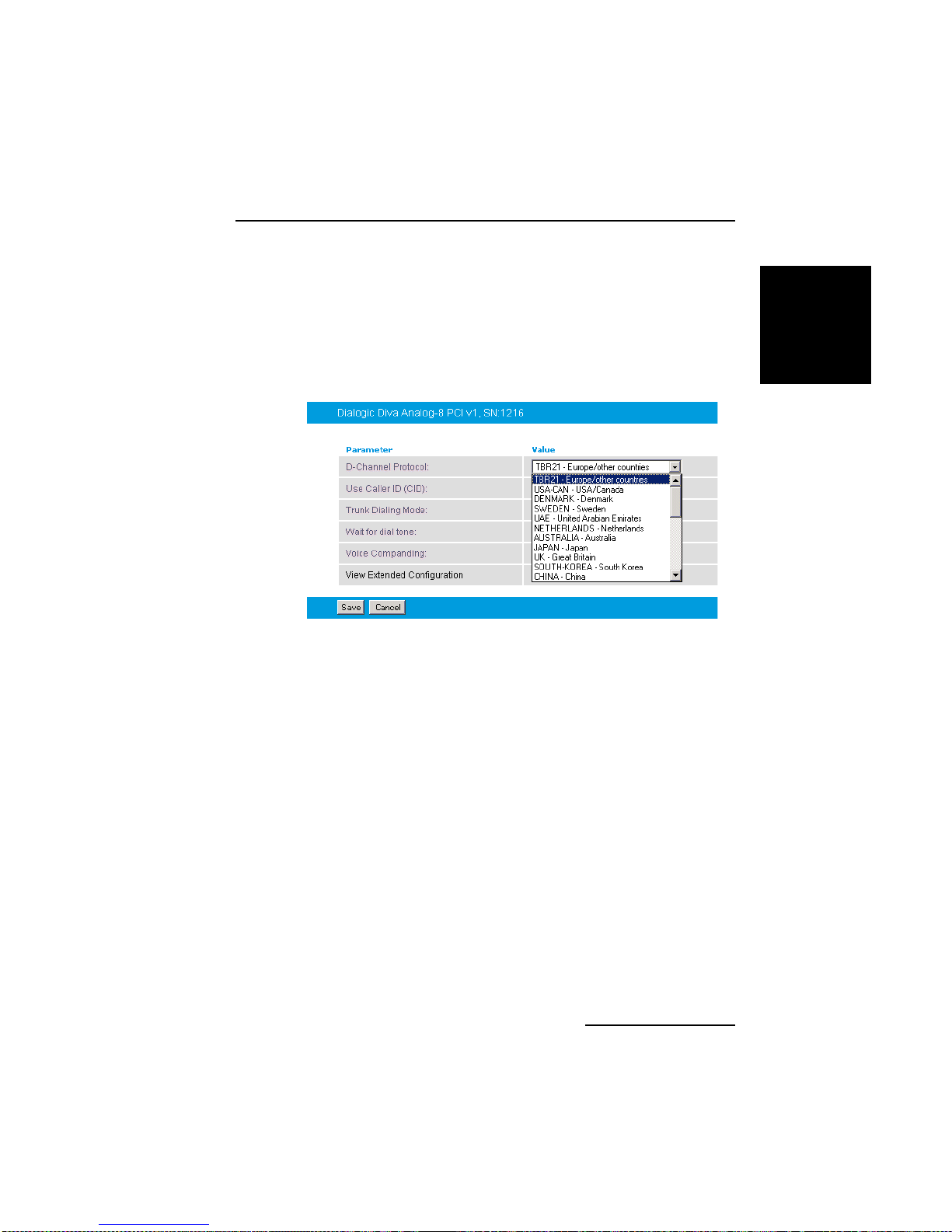
Dialogic® Diva® Media Board Installation Guide
Under Linux:
1. Open the Dialogic
®
Diva® Linux System Release software web
interface
2. Click Board configura ti on and select the Dialogic
®
Diva® Media
Board you want to configure.
3. In the Board Configuration - Detail select your country-specific
protocol from the dropdown menu next to D-Channel Protocol.
Note: The above graphic shows the parameters and values for a Diva
Analog Media Board configuration. The available D-channel protocols
depend on the in stalled Div a Media Board. The menu options for Diva BRI
and PRI Media Boards are slightly different as well.
• These products do not perform automatically repeated call attempts;
however , they do not include protection against repeated call requests from
the controlling application software.
• T o meet the requirements of TBR 21 § 4.8.3, the application software shall
not submit call requests that violate the following rules:
• The number of repeated call attempts [to the same number] is
restricted to 15.
• The interval between subs equent call attempts [t o the same number]
is at least 5 seconds.
ENGLISH
page 59
Page 60

International Regulatory Information
EU Declaration of Conformity
ENGLISH
Dialogic Corporation declares that thi s equipment is in compliance with the
Radio and Telecommunication Terminal Equipment directive 1999/5/EC with
requirements covering the Electromagnetic Compatibility Directive
2004/108/EC, Low Voltage Directive 2006/95/EC, and the RoHS Directive. A
detailed declaration of con for m ity for this product can be foun d at :
www.dialogic.com/declarations
These products are compatible with analog lines to the Public Switched
Telephone Network (PSTN) in the following countries:
Austria, Belgium, Cyprus, Czech Republic, Denmark, Estonia, Finland, France,
Germany, Greece, Hungary, Iceland, Ireland, Italy, Latvia, Liechtenstein ,
Lithuania, Luxembourg, Malta, The Netherlands, Norway, Poland, Portugal,
Slovakia, Slovenia, Spain, Sweden, Switzerland, and The United Kingdom.
Manufacturer's office in European Union:
Dialogic
Unit O3 North Ring Business Park
Santry
Dublin 9
IRELAND
Te l: +35 3 1 630 9000
Fax: +353 1 630 9099
CS: Dialogic Corporation tímto prohlašuje, že tento ITE je ve shodě se základními
požadavky a dalšími příslusnými ustanoveními směrnice 1999/5/ES.
DA: Undertegnede Dialogic Corporation erklærer herved, at følgende udstyr
ITE overholder de væse n tlig e krav og øvr ige re le vante k rav i direk t iv
1999/5/EF.
DE: Hiermit erklärt Dialogic Corporation, da ss sich das Gerät ITE in
Übereinstimmung mit den grundlegenden Anforderunge n und den übrigen
relevanten Besti m mu n ge n de r Ric htlinie 1999/5/EG bef in d e t.
…‘≈
EL: Ã≈ ‘«Õ —¡–œ’”¡ Dialogic Corporation ƒ«ÀŸÕ≈… œ‘…
”’ÃÃœ–÷ŸÕ≈‘¡…
—–œ” ‘…” œ’”…Ÿƒ≈…” ¡—¡…‘«”≈…” ¡… ‘…” Àœ…—≈” ”◊≈ ‘…≈” ƒ…¡‘¡Œ≈…” ‘«”
œƒ«√…¡” 1999/5/EK.
EN: Hereby, Dialogic Corporation, declares that this ITE is in compliance
with the essent ial re qu i re m ents and other rele vant pr ovi sio n s of Dir ect i ve
1999/5/EC.
ES: Por medio de la presente Dialogic Corporation declara que el ITE cumple
con los requisitos esenciales y cualesquiera otras disposiciones aplicables o
exigibles de la Dire c tiva 19 99/ 5/E C .
ET: Käesolevaga kinnitab Dialogic Corporat ion seadme ITE vastavust
direktiivi 1999/5/EÜ põhinõuetele ja nimetatud direktiivist tulenevatele
teistele asjakohastele sätetele.
page 60
Page 61

Dialogic® Diva® Media Board Installation Guide
t
FI: Dialogic Corporation vakuuttaa täten että ITE tyyppinen laite on
direktiivin 1999/5/EY oleellisten vaatim usten ja sitä koskevien dir et iiv in
muiden ehtojen mukainen.
FR: Par la présente Dialogic Corporation déclare que l’appareil ITE est
conforme aux exig ences essentiell es et aux autres dispositions pe rtinentes de
la directive 1999/5/C E.
HU: Alulírott, Dialogic Corporation nyilatkozom, hogy a ITE megfelel a
vonatkozó alapvetõ követelményeknek és az 1999/5/EC irányelv egyéb
elõírásainak.
IC: Hér m eð lýs ir Dialogic Corporation yfir því að ITE e r í sa m ræmi við
grunnkröfur og aðrar kröfur, sem gerðar eru í tilskipun 1999/5/EC.
IT: Con la presente Dialogic Corporation dichiara che questo ITE è
conforme ai requ i si ti es s en z iali e d a lle altre dis p os iz io n i pe rti ne n ti st a bi lite
dalla direttiva 1999/5/CE.
LT: Šiuo Dialogic Corporation deklaruoja, kad šis ITE atitinka esminius
reikalavimus ir kitas 1999/5/EB Direktyvos nuostatas.
LV: Ar šo Dialogic Corporation deklarē, ka ITE atbilst Direktīvas 1999/5/EK
būtiskajām prasībām un citiem ar to saistītajiem noteikumiem.
MT:
Hawnhekk, Dialogic Corporation, jiddikjara li dan ITE jikkonforma mal-htigijie
essenzjali u ma provvedimenti ohrajn relevanti li hemm fid-Dirrettiva 1999/5/EC.
NL: Hierbij verklaart Dialogic Corporation dat het toestel ITE in
overeenstemming is met de essentiële eisen en de andere relevante
bepalingen van richtlijn 1999/5/EG.
NO: Dialogic Corporation er klærer herv ed at utstyret ITE er i samsv ar med
de grunnleggende krav og øvrige relevante krav i direktiv 1999/5/EF.
PL: Dialogic Corporation niniejszym oświadcza, że ITE spełnia wszystkie istotne
wymagania i odpowiednie ustalenia dyrektywy 1999/5/EC.
PT: Dialogic Corporation declara que este ITE está conforme com os
requisitos esse nc ia is e outras disposições da Dir ect i va 1999 /5/ CE .
SL: Dialogic Corporation izjavlja, da je ta ITE v skladu z bistvenimi zahtevami in
ostalimi relevantnimi določili direktive 1999/5/ES.
SK: Dialogic Corporation týmto vyhlasuje, že ITE spĺňa základné požiadavky a všetky
príslušné ustanovenia Smernice 1999/5/ES.
SV:Härmed intygar Dialogic Corporation att denna ITE står l
överensstämmelse med de väsentliga egenskapskrav och övriga relevanta
bestämmelser som framgår av direktiv 1999/5/EG.
ENGLISH
page 61
Page 62
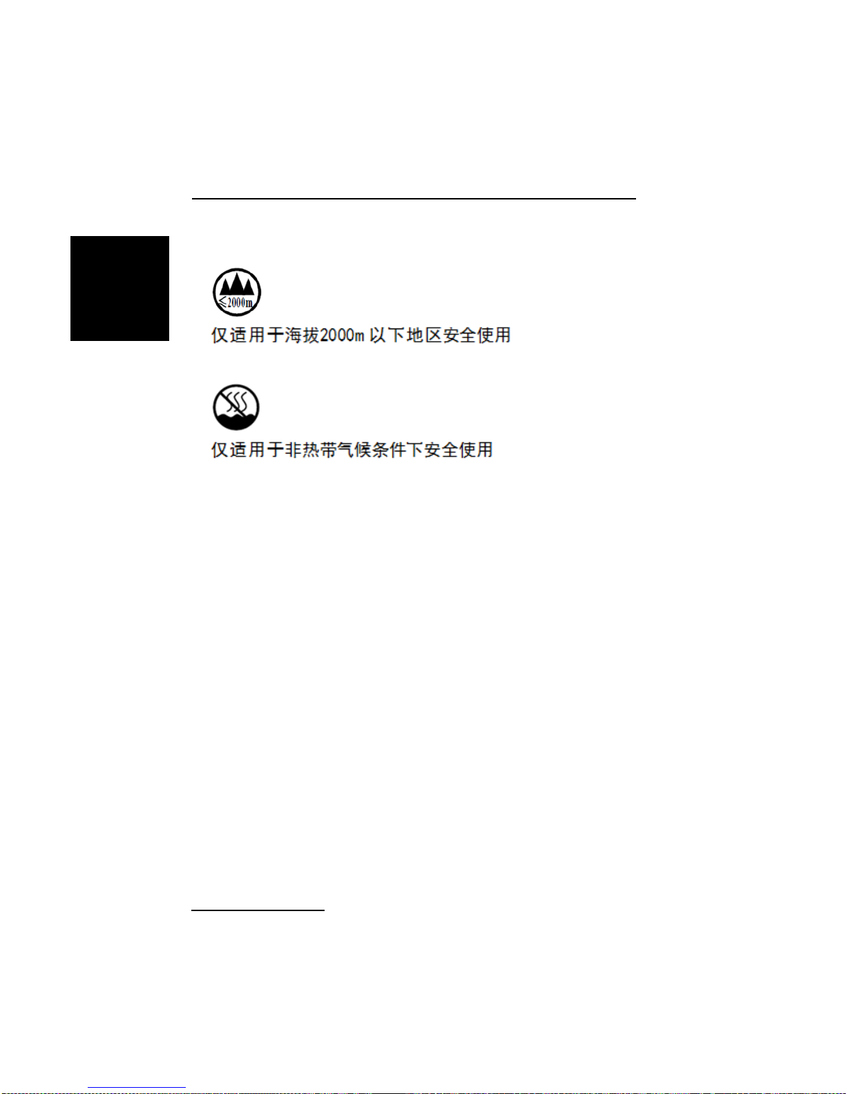
International Regulatory Information
Regulatory information for China
ENGLISH
Only safe to be used in altitudes of 2000m or less.
Only safe to be used in non-tropical climates.
Product Environmental Information
In August 2005, the European Union Directive on Waste Electrical and
Electronic Equipment (20 02/ 96/ EC) and its am en dm e nt (20 03/ 108 /EC ),
collectively known as the WEEE Directive, came into force throughout most
of the European Union. This Dialogic product comes within the scope of the
WEEE Directive.
We are confident that this product will provide you with many years of reliable
service. Ultimately, a time may come when the produ ct wi ll no longer meet
your needs or will become un-economical to repair. It is at that stage that we
ask for your co-operat ion in re c yclin g thi s pr od u c t in th e sp ir it of the WEEE
directive.
While Dialogic has taken great care to minimize the environmental burden of
this product by careful design and manufacturing, we ask you to help us to
further minimize the envir onm e n tal burden of this product by rec ycl ing it.
Please do not dispose of this product through municipa l or general waste
systems because it contains mater ials that can be economically recycled .
page 62
Page 63

Dialogic® Diva® Media Board Installation Guide
Like all electrical and electronic equipment, including televisions and
computers, it may cont ai n small amounts of materials which could lead to
environmental damag e. To minimize any en vi ro nmen ta l damage we as k y ou
to have this product recycled by:
• bringing it to the recycling collection point in your company
• by handing it into th e s tor e where you are purch a si n g the re pla c e m en t
• by delivering it to a local bring-center in your area.
No charge can be imposed on you for t hi s re c y cl ing
service in the European Union as Dialogic has paid for
recycling thi s product when it was placed on the market.
These are requirements of the WEEE Directive. We
thank you in advance for your cooperation and for
working with Dialogic to protect our environment.
Power consumption
WARNING: Check that power supply will not be overloaded. Maximum
power consumption of the board is stated in Technical
Specifications on page 42. The user should check that the total
power drawn by the host comp uter, the Dialogi c
Board and any other peripherals, must not exceed the capability
of the host Power Supply Unit. The Diva Media Board does not
draw power from the IS D N netw or k.
®
Diva® Media
ENGLISH
User/Installer instructions
Dialogic® Diva® Media Board (internal models only)
page 63
Page 64

International Regulatory Information
Important safety considerations when installing into a host
ENGLISH
computer system
WARNING: The telephones cord(s) must remain disconnected from the
telecommunications system until the Dialogic
®
Diva® Media
Board has be en properly instal led within the hos t which provides
the necessary protection of the operator.
Proper installation of the telecommunication card requires that
the Diva Media Board is screwed to the metal bac kplate of the
PC. This ensures p roper gr ounding, which is necessar y for y our
safety.
If it is subsequently desired to open the host equipment for any
reason, the telephones cord(s) must be disconnected prior to
effecting access to the t elecommunications Diva Media Board.
WARNING: Never install telephone jacks in wet locations.
Never touch non-insulated telephone wires or terminals unless
the telephone line has been disconnected at the network
interface.
Use caution when installing or modifying telephone lines.
Installation within a spare slot position
WARNING: It is essential that, when other option cards are introduced which
use or generate a hazardous voltage, the minimum creepages
and clearances specified in the table below are maintained.
Suitable user protection to ensure compliance with EN 60950
should be present on the card. A hazardous voltage is one which
exceeds 42.4 V peak ac or 60 V dc. If you have any doubt, seek
advice from a competent en gineer before installing other
Dialogic
®
Diva® Media Boards into the host equipment.
page 64
Page 65
Dialogic® Diva® Media Board Installation Guide
The equipment must be installed such that with the exception of the
connections to the host, clear ance and cre epage distances shown in the table
below are maintained between the Dialogic
®
Diva® Media Board and any other
assemblies which use or generate a voltage shown in the table below.
Clearance
X mm
2.0 2.4 (3.8) up to 50
2.6 3.0 (4.8) up to 125
4.0 5.0 (8.0) up to 250
4.0 6.4 (10.0) up to 300
Creepage
Y mm
Voltage used or generat ed by ot her
parts of the host or expansion card
Vrms or Vdc
The larger distance shown in brackets applies where the local environment
within the host is subject to conductive pollution or dr y non- cond uctive
pollution which could become conductive due to c onden sat ion . Failure to
maintain these minimum distances would invali date the approval.
The clearance dis t ance X is the short es t distance in air be tween two point s .
The creepage path Y (along surfaces ) is the shortest distance between the
same two points.
Regulatory informatio n fo r Australia
Dialogic is required to provide the following information as a condition of the
telecommunications conformity of Dialogic
You may also be responsible for meeting requirements other than tho s e
outlined in this document.
Note: Failure to meet the requirements listed may render the products
non-compliant, with the user liable to significant penalties under the
Telecommunications Act.
WARNING: This customer equipment is to be installed and maintained by
service personnel as defined by AS/NZS 60950.1:2011
Service Personnel. It may be hazardous if your computer is
not properly plugged in and grounded.
®
telecommunications products.
ENGLISH
CAUTION: This equipment must be installed and serviced by qualified
personnel. No user accessible parts inside.
page 65
Page 66

International Regulatory Information
ENGLISH
IMPORTANT: This equipment will be inoperable when mains power fails.
• This customer equipment shall only be installed in a PC that requires the
use of a tool to gain access to internal parts (e.g., this customer equipment
must not be installed in a PC with a "flip lid").
®
• Proper installation of the Dialogic
Diva® Media Board requires that it is
screwed to the metal bac kplate of the computer. This ensures proper
grounding, which is necessary for safety purpose s.
• This customer equipment may only be installed in host equipment where
there is at least 2 mm of air gap between the customer equipment and
adjacent boards (PCBs).
• Only compliant line cord set(s) shall be used as replacements with this
customer equipment.
These products shall be used in a manner that complies with the technical
standards ACA TS 001 and ACA TS 002:
• The application software shall answer an incoming call by seizing the line
at least 2 seconds after the start of an application of ring signal from a
PSTN. A maximum time of 15 seconds is recommended.
• The application software shall comply with the following requirements
before the commencement of dialing:
• When dial tone detection is enabled, the application software may
commence dialing after the presence of dial t on e is validated.
• If dial tone detectio n is not en abled or if dia l tone is n ot dete cted, th e
application software shall commence dialing no less than 2 seconds
after the line is seized.
• A total of 10 call attempts are allowed to a telephone number, with a
minimum period of 2 seconds between calls. If the call does not connect
after 10 attempts, 30 minutes must expire before automatic redialing may
be initiated.
• These products must conn ect to th e teleco mmunicat ions net work onl y by
means of cables that meet applicable ACA standards and
telecommunication s con formity.
page 66
Page 67

Dialogic® Diva® Media Board Installation Guide
• These products must only be used in a data terminal equipment (DTE),
e.g., computer , that has a screw-down cov er or lid. Because unsafe voltages
(TNV) exist on these products, disconnect the product from the telephone
line while the cover of the DTE is removed.
Note: This does n ot apply to Dialogi c
®
Diva® V-xPRI PCIe HS and V-xPRI
PCIe FS Media Boards.
• These products will not automatically put the channel back to the on-hook
state when the calling party hangs up. The application is tasked to handle
this function on the detection of a discon nect tone or loop current drop.
Regulatory informatio n for Japan
Product Cer tif i c ate Nu mbe r
Diva BRI-2
Diva UM-BRI-2
Diva 4BRI-8
Diva UM-BRI-2
Diva PRI/E1/T1-CTI
Diva PRI/E1/T1-8
Diva PRI/T1-24
Diva PRI/T1-24 PCIe
Diva V-2PRI CD06-0488001
Diva V-4PRI CD06-0489001
Diva Analog-4
Diva Analog-8
Diva UM-Analog-4
Diva UM-Analog-8
CD-02-0870JP
C01-0472JP L01-0152
CD05-0558001
CD05-0557001
A05-0055003
ENGLISH
page 67
Page 68

Suppliers Declaration of Conformity
Suppliers Declaration of Conformity
ENGLISH
The suppliers declaration of conformity are updated constantly. An extract
form the complete list c an be fou nd on the followin g pages. The comple te list
is available on the Dialogic web site under www.dialogic.com/declarations
Customer Service
.
Dialogic provides various options and arrangements for obtaining technical
support for your Dialog ic
Dialogic
®
Diva® Support Tools first before contacting your Dialogic supplier.
Also, we suggest that you visit the Dialogi c
®
product. We recommend that you use the
®
Services & Support site, as it
includes detailed information about a variety of topics. In the unusual case
that neither your supplier nor the information on the Services & Support site
is able to adequately address your support issue, you can contact Dialogic
Customer Support.
For more info rmation see:
• Dialogic
® Diva® Support Tools
• Dialogic Services & Support web site
• Dialogic Corporation Customer Support
Dialogic® Diva® Support Tools
If an issue occurs during the operation of your Dialogic® Diva® product, use
the following Dia lo gi c
systems):
®
•Dialogic
Diva® Line Test: With the Diva Line Test tool, you can test your
hardware and perform simple phone test calls, call transfers, or basic
inbound and outbound calls.
®
•Dialogic
Diva® Diagnostics: With the Diva Diagnostics tool, you can write
traces for each Dialogic
•Dialogic
®
Diva® Management tool: With the Diva Management tool, you
can view the current status of the connected lines, the active connections,
and the history of the connections.
For more information about the tools, see the respective online help files.
If you cannot address the issue through use of these tools, conta ct your
Dialogic supplier.
®
Diva® Support Tools (only for Windows® operating
®
Diva® Media Board or driver into a file.
page 68
Page 69

Dialogic® Diva® Media Board Installation Guide
Dialogic Services & Support we b site
If your supplier is unable to help you to address your issue, you can visit the
Services & Support web site. There, you get access to:
• detailed information about the Dialogic
®
ProTM Services (1,3, or 5 year
24/7 service contracts) at http://www.dialogic.com/support/DialogicPro/
• a help web section for Dialogic® products at
http://www.dialogic.com/support/helpweb
• a download section, to install the current version of your software at
http://www.dialogic.com/support/downind.asp
• a training section, with information about webinars as well as online and
onsite trainings, at http://www.dialogic.com/training/default.htm
• a manuals se ct ion, that includes cur rently available docu mentation, at
http://www.dialogic.com/manuals/default.htm
• technical discussion forums about different developer-specific Q&A at
http://www.dialogic.com/forums/category-view.asp
• the Dialogic Customer Support site. For detailed information about how to
contact the Customer Suppo rt, see D
ialogic Corporation Customer Support
below.
Dialogic Corporation Customer Support
If the information on the Dialogic® Service & Support web site was not
sufficient to help you solve your problem, you can contact Dialogic Customer
Support.
To provide help, Dialogic Cu st om e r Su p po rt wi ll like ly ne ed from you:
®
• A debug trace (see Dialogic
DivaTrace.chm), and
• A copy of your active configuration (see Dialogic
Manager Online Help file - DSMain.chm).
See www.dialogic.com/support/contact
Diva® Diagnostics Online Help file -
®
Diva® Configuration
for details on how to contact Dialogic.
ENGLISH
page 69
Page 70

Customer Service
page 70
Page 71

Dialogic® Diva® Karten Installationsanleitung
Dialogic® Diva® Karten Installationsanleitung
Mit den Dialogic® Diva® Karten können Sie über ISDN-Basisanschlüsse (S0),
Primärmultip le xa ns c hlüs s e (S
Verbindungen für eine Vielzahl von Anwendungen realisieren. Diese
Installationsanleitung beschreibt die Installation und den Anschluss Ihrer Diva
Karte, liefert technische Daten der Karte und gibt einen Überblick über die
verfügbare Online-Dokumentation.
) oder Analoganschlüsse schnellste
2M
Unterstützte Dialogic® Diva® Karten
Die Dialogic® Diva® Produktpalette beinhaltet die folgenden Diva Karten:
Dialogic® Diva® BRI Karten
Diva BRI Karten sind leistungsstarke und zum Teil aktive ISDN-Karten für den
ISDN-Basisanschluss (BRI). Diese Diva Karten unterstützen sowohl analoge
als auch digitale Gegenstellen.
Diva BRI PCI: Diva BRI PCIe:
• Diva BRI-CTI • Diva BRI-2 PCIe
• Diva BRI-2FX • Diva 4BRI-8 PCIe
•Diva BRI-2 •Diva UM-BRI-2 PCIe
•Diva 4BRI-8 •Diva UM-4BRI-8 PCIe
DEUTSCH
•Diva UM-BRI-2
•Diva UM-4BRI-8
Dialogic® Diva® PRI und E1 Karten
Diese Diva Karten sind zum Teil aktive Hochleistungs-ISDN-Karten für den
ISDN-Primärmultiplexanschluss (PRI) und können sowohl für digitale als auch
für analoge Dienste einge setzt werden.
Diva PRI PCI: Diva V-PRI PCI: Diva V-xPRI PCI:
• Diva PRI/E1/T1-CTI • Diva V-PRI/E1-30 • Diva V-2PRI/E1-60
• Diva PRI/E1/T1-8 • Diva V-4PRI/E1-120
•Diva PRI/E1-30
•Diva UM-PRI/E1-30
Seite 71
Page 72

Unterstützte Dialogic® Diva® Karten
Hinweise für Diva V-xPRI PCIe:
• Die Abkürzung HS steht für "half size" (halbe Größe). Die genauen
Abmessungen finden Sie auf Seite 104. Diese Karten können in einigen
Ländern mit dem Gerätetypnamen "VPRIHS" zugelassen sein.
• Die Abkürzung FS steht für "full size" (volle Größe). Die genauen
Abmessungen finden Sie auf Seite 105. Diese Karten können in einigen
Ländern mit dem Gerätetypnamen "VPRIFS" oder mit den Modellnamen
"Diva V-4PRIFS" und "Diva V-8PRIFS" zugelassen sein.
Diva PRI PCIe: Diva V-PRI PCIe: D iva V-xPRI PCIe:
• Diva PRI/E1/T1-CTI PCIe • Diva V-PRI/E1-30 PCIe • Diva V-1PRI/E1/T1-30 PCIe
DEUTSCH
• Diva PRI/E1-30 PCIe • Diva V-2PRI/E1/T1-60 PCIe
• Diva UM-PRI/E1-30 PCIe • Diva V-4PRI/E1/T1-120 PCIe
HS
HS
HS
• Diva V-4PRI/E1/T1-120 PCIe
FS
• Diva V-8PRI/E1/T1-240 PCIe
FS
Dialogic® Diva® Analogkarten
Diva Analogkarten können über RJ-10- oder RJ-45-Standardanschlüsse an
analoge Telefonanlagen oder das öffentliche analoge Netz angeschlossen
werden. Aufgrund von High-Performance Media Processing Funktionalitäten
kann die Diva Analog die Systemleistung verbessern.
Diva Analog PCI: Diva Analog PCIe:
• Diva Analog-2 • Diva Analog-2 PCIe
• Diva Analog-4 • Diva Analog-4 PCIe
• Diva Analog-8 • Diva Analog-8 PCIe
• Diva UM-Analog-2 • Diva UM-Analog-2 PCIe
• Diva UM-Analog-4 • Diva UM-Analog-4 PCIe
• Diva UM-Analog-8 • Diva UM-Analog-8 PCIe
Seite 72
Page 73

Dialogic® Diva® Karten Installationsanleitung
Unterstützte Betriebssysteme
Dialogic® Diva® Karten unterstützen die folgenden Betriebssysteme:
• Linux (die meisten der bekannten Kernels und Distributionen)
•Microsoft
•Microsoft
•Microsoft
•Microsoft® Windows Server® 2003
•Microsoft
Hinweis: Dialogic
einem Computer mit dem Betriebssystem Mi crosoft
Business Server (SBS) einsetzen. Die Software und Dokument ation für die
Microsoft
entsprechenden Microsoft
®
Windows® 7
®
Windows Server® 2008
®
Windows Vi st a
®
Windows® XP
®
Diva® BRI und UM-BRI Karten können Sie zusätzlich in
®
Windows® Small Business Server finden Sie auf der
®
®
Windows® Small
®
Windows® Small Business Server CD-ROM.
Dialogic® Diva® Online-Dokumentation
Die Diva Online-Dokumentation ist mit den Treibern der Dialogic® Diva®
System Release Software oder auf der Dialogic Internetseite unter:
http://www.dialogic.com/manuals/default.htm
Online-Dok u m entation beschr eibt die Installa tio n de r Diva System Release
Software, deren Leistungsmerkmale und deren Konfigurations-, Diagnoseund Testprogramme.
verfügbar. Die
DEUTSCH
Seite 73
Page 74

Allgemeine Sicherheitshinweise
Allgemeine Sicherheitshinweise
Die folgende n Sic h e rhe itshinweise di enen Ihrer pers önlichen Sicher h e it un d
schützen den Computer und die Dialogic
®
Diva® Karte sowie die
Arbeitsumgebung vor möglichen Schäden.
®
WARNUNG Alle Dialogic
Diva® Karten
Computer , in denen D iva Karten eingesetzt we rden, müssen den
CE-Richtlinien entsprechen, um Gesundheitsschäden und
Schäden am Computer und an der Diva Karte zu vermeiden.
Ziehen Sie das analoge oder ISDN-Kabel aus dem Computer,
bevor Sie das Gehäuse Ihres Computers für die Installation
Ihrer Diva Karte oder aus einem anderen Grund abnehmen, um
DEUTSCH
Gesundheits- und Materialschäden zu vermeiden.
Achten Sie darauf, die Metallschiene der Diva Karte zu
verschrauben, so dass sie fest mit dem Computergehäuse
verbunden ist. Dadurch wird die richtige Erdung sichergestellt
und somit Gesundheits- und Materialschäden vermieden.
Installieren Sie ISDN- oder TAE-Anschlussbuchsen nie in
feuchter Umgebung.
Berühren Sie unter keinen Umständen nicht isolierte T eile von
Te lef onkabeln oder Telefonanlagen außer wenn die
Telef onleit ung von der Netzwe rks ch nittstell e getr ennt wur de .
Seien Sie beim Installieren oder Modifizieren von
Telef onleitung en vorsicht ig.
Telefongesellschaften warnen vor Überspannungen,
typischerweise durch Blitzeinschläge. Diese können sehr
schädlich für Apparate sein können, die an Wechselspannungen
angeschlossen sind. Das Be nutzen von einem
Überspannungsschutz an der Wechselstromleitung wird
empfohlen.
®
Dialogic
Dialogic
Diva® BRI und PRI Media Boards, außer
®
Diva® V-xPRI PCIe HS und V-xPRI PCIe FS
Bei BRI und PRI Signalen kann Telefonnetzwerkspannung
anliegen. Deshalb sollten ISDN BRI, ISDN PRI und E1 Leitungen
nur von befugtem Servicepersonal instaliert und Instand
gehalten werden . Das bet rif ft bes onders Installati one n in de n
USA und Austral ien. Nicht sachgerecht angeschlossene und
geerdete Computer , können Gesundheits- und Materialschäden
verursachen.
Seite 74
Page 75

Dialogic® Diva® Karten Installationsanleitung
WARNUNG Dialogic® Diva® V-xPRI PCIe HS und V-xPRI PCIe FS
Bei Diva V-xPRI PCIe HS und V-xPRI PCIe FS liegt keine
Tel efon netzwe rkspa nnu ng an, da sie mit einer
Schutzkleinspannung (SELV) betrieben werden.
®
Dialogic
Diva® V-2PRI PCI, V-4PRI PCI, V-4PRI FS
PCIe und V-8PRI FS PCIe
Diva V-2PRI und V-4PRI Karten können ca. 20 Watt Leistung
benötigen.
Diva V-4PRI FS PCIe und V-8PRI FS PCIe Karten können ca.
24 Watt Leistung benötigen.
Wenn Sie mehrere dieser Diva Karten in Ihrem System
installiert haben, kann die Stromversorgung überlastet
werden. Stellen Sie sicher, dass die Stromversorgung nicht
überlastet wird und dass Ihr Computer ausreichende Kühlung
gewährleistet, um Gesundheits- und Materialschäden zu
vermeiden.
WICHTIG Dialogic
®
Diva® BRI und PRI Karten
Diva BRI und PRI Karten wurden getestet und entsprechen
bezüglich der elektromagnetischen Verträglichkeit, der
Sicherheit und der Kompatibilität der ISDN-Schnittstelle den
Richtlinien in der E U, in No rd a m er ika und in anderen
wichtigen Wirtsc haftsräumen. L esen Sie die entspr echenden
Informationen im Kapitel Zulassungsinformationen
auf
Seite 108, bevor Sie die Diva Karte installieren und einsetzen.
Die Kabel für die PRI Schnittstellenanschlüsse müssen
abgeschirmt sein.
®
Dialogic
Diva® PRI PCIe und V-xPRI PCI und PCIe
Die korrekte Funktionsweise der Diva PRI PCIe und Diva
V-xPRI PCI und PCIe Karten kann nur gewährleistet werden,
wenn die Diva Karten innerha l b de r zu ge las s e nen
Betriebstemper atu r eing esetzt werden , siehe Seite 98. Wird
die Temperatur überschritten, erstellt das System eine
Trace-Datei m it den Informatio nen über die
Betriebstemperatur.
®
Dialogic
Diva® Analog
Benutzen Sie nur Kabel mit American Wire Gauge (AWG) Nr.
26 oder höher, um ein korrektes Funktionieren zu
gewährleisten.
DEUTSCH
Seite 75
Page 76

Vorbereitungen
Vorbereitungen
Stellen Sie zunächst sicher, dass alle erforderlichen Komponenten zur
Installation Ihrer Dialogic
®
Diva® Karte und der Dialogic® Diva® System
Release Software bereitlieg en:
Komponente Beschreibung
Computer Ihr Computer muss verfügen über:
DEUTSCH
Lieferumfang der
®
Dialogic
ISDN-Karten
Lieferumfang der
Dialogic
Analogkarte
Kabel Bei Dialogic
CSU/DSU Dialogic
Diva®
®
Diva®
• einen freien PCI-Steckplatz für PCI-Bus Karten
(für Dialogic
®
Diva® V-2PRI und V-4PRI Karten gemäß PCI 2.2)
• einen freien PCIe-Steckplatz x1 oder x4, 1.0a kompatibel für
PCIe-Bus Karten
Andere Steckplätz e, z. B. x4, x8, x16 kön nen genu tzt werd en,
wenn sie vom BIOS und vom Betriebssystem unterstützt
werden.
Hinweis: Der PCIe-Steckplatz x4 wird nur für die Installation
der Dialogic
benötigt.
• ein installiertes Betriebssystem:
Linux,
Microsoft
Microsoft
Microsoft
Microsoft® Windows Server® 2003,
Microsoft
• mindestens 15 MB freien Speicherplatz auf der Festplatte für
die Dialogic
Der Lieferumfang Ihrer Diva ISDN -Karte enthält folgende
Komponenten:
®
Diva® V-4PRI PCIe FS und V-8PRI PCIe FS Karten
®
Windows® 7
®
Windows Server® 2008,
®
Windows Vista
®
Windows® XP
®
Diva® System Release Software
®,
• Diva ISDN-Karte
• ein oder mehrere benötigte ISDN RJ-45 V erbindungskabel (nur
für Dialogic
®
Diva® BRI
)
•Dialogic® Diva® V-8PRI PCIe FS Media Board: vier Kabel mit
Dual-Adapter
®
•Dialogic
Der Lieferumfang Ihrer Diva Analogk art e enthäl t fo l g end e
Komponenten:
Diva® Karten Installationsanleitung
• Diva Analogkarte
• Verbindungskabel zum Anschluss an die Analogleitung
• Alle Dialogic
®
Diva® Analog-8: vier Kabel mit Dual-A dapter
• Diva Karten Installationsanleitung
®
Lieferumfang, sie müssen von einem Händler be zo gen werden.
HS, V-4PRI PCIe FS und V- 8PRI PCIe FS haben kein e eingebaute
CSU/DSU (Channel Service Unit/Data Service Unit). Diese muss
von einem Händler bezogen und extern angeschlossen werden.
Sehen Sie dazu Anschließen einer Dialogic
Seite 81.
Diva® PRI Kar ten gehören die RJ-45 Kabe l nicht zum
®
Diva® V-1PRI PCIe HS, V-2PRI PCIe HS, V-4PRI PCIe
® Diva® PRI auf
Seite 76
Page 77

Dialogic® Diva® Karten Installationsanleitung
Komponente Beschreibung
ISDN-Basis- (S0),
Primärmultiplexanschluss (S
Analoganschluss
Informationen zum
Anschluss
2M
Die Anschlüsse werden von der zuständigen Telefongesellschaft
eingerichtet.
) oder
Achten Sie darauf, dass Sie den/die zu Ihrer Dialogic
passenden Anschluss/Anschlüsse erhalten.
Ihre T elefongesellschaft muss die folgenden Informationen
bereitstellen:
• ISDN- oder analoge Rufnummern für jede Leitung
• ISDN-Übertragungsprotokoll (D-Kanal-Pro toko ll):
Das Protokoll ist normalerweise abhängig von der Region.
Beispiele für gebräuchliche Übertragung sprotokolle sind:
Euro-ISDN DSS1 (wird in Europa verwendet und auch als
ETSI-Standard bezeichnet), 1TR6 (wird hauptsächlich in
digitalen Nebenstellenanlagen in Deutschland verwendet).
®
Diva® Karte
Installation
Dieser Abschn itt be s c hre ib t die In st a llati on Ih re r Dialog ic® Diva® Karte und
das Anschließen an die Leitung.
Führen Sie die folgenden Schritte durch, um Ihre Diva Karte erfolgreich
einzusetzen:
• (A) Die Diva Karte in Ihre n Co mputer einstec ken , wie unten beschri eb en.
• (B) Die Diva Karte anschließen, wie auf Seite 79 beschrieben.
•(C) Die Dialogic
Seite 91 beschrieben.
Hinweis: Halten Sie Ihr Computerhandbuch während der Installation der
Karte bereit.
®
Diva® System Release Software installiere n , wie auf
DEUTSCH
®
(A) Die Dialogic
Diva® Karte in Ihren Computer einstec ke n
1. Schalten Sie den Computer und alle Peripheriegeräte aus und ziehen Sie
von allen Geräten den Stecker, um Verletzungen zu vermeiden.
2. Entladen Sie die statische Aufladung Ihres Körpers, indem Sie das
Metallgehäuse berü hren (die nicht- lackierte Rückse ite des Computer -Gehäuses).
3. Ziehen Sie das ISDN-Kabel, wenn vorhanden, und das Netzkabel vom
Computer ab.
4. Nehmen Sie die Abdeckung des Computers ab (siehe
Computer-Handbuch).
5. Suchen Sie in Ihrem Comp uter einen freien PCI- oder PCIe-S teckplatz.
6. Lösen Sie die Schr aube o der l ocker n Sie d en Cli p. Achten Si e dar auf, die
Schraube nicht zu verlieren. Entfernen Sie ggf. die hintere Metallschiene
des Steckplatzes.
Seite 77
Page 78
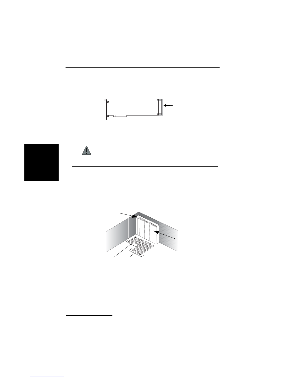
Installation
7. Wenn Ihre Dialogic® Diva® Karte ein en Haltebügel hat und dieser bei de r
Installation stört, können Sie ihn auch abmontieren. Er ist lediglich eine
Installationshilfe und trägt nicht zum Funktionieren der Diva Karte bei.
Haltebügel
8. Bevor Sie die Div a Karte in d en Steckplatz einsetzen, l esen Sie folgend en
Sicherheitshinweis:
VORSICHT: Damit keine Hardwar eschäden auftreten, dürfen Sie d ie Diva
Karte, je nach T yp, nur in einen PCI- oder PCIe-Steckplatz
DEUTSCH
einsetzen. Wenn Sie eine Diva Karte in einen Steckplatz
anderen Typs einsetzen, können die Karte, der Computer
oder beide beschädigt werden.
9. Setzen Sie die Diva Karte in den Steckplatz ein. Stellen Sie sicher, dass
die Diva Karte weder die CPU, noch die Speichermodule oder andere
Bauteile auf der Hauptplatine berührt.
®
Hinweis: Die Dialogic
Diva® V-2PRI PCI und V-4PRI PCI haben
zusätzlich zum PCI-Bus einen H.100-Bus auf der Karte, der nicht
betriebsbere it ist. Setzen Sie Ihre Diva Karte nu r mi t dem PCI -Bus in
einen PCI-Steckplatz ein.
Schraube oder Clip
Metallschiene
PCIe-Steckplatz
PCI-Steckplatz
Seite 78
Page 79
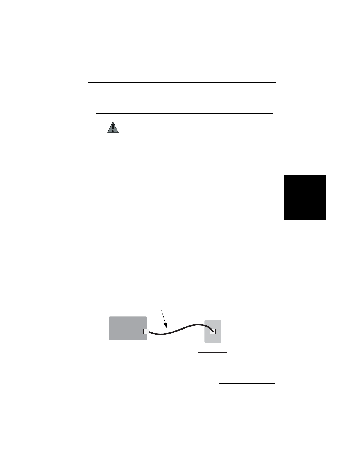
Dialogic® Diva® Karten Installationsanleitung
10. Befestigen Sie die Diva Karte mit der Schraube oder dem Clip, damit sie
fest mit dem Gehäuse des Computers verbunden ist
.
VORSICHT: Achten Sie darauf, die Metallschiene der Diva Karte zu
verschrauben, so dass sie fest mit dem Computergehäuse
verbunden ist. Dadurch wird die richtige Erdung
sichergestellt und somit Verletzungen und Schäden am
Computer und an der Diva Karte vermieden.
11. Bringen Sie die Abdeckung des Computer s wied er an (siehe Comp ute rHandbuch).
(B) Die Dialogic
®
Diva® Karte anschließen
Das Anschließen der Diva Karte ist abhängig vom Kartentyp:
®
• Wenn Sie eine Dialogic
Diva® BRI anschließen, folgen Sie den
Anweisunge n a uf Seite 79.
®
• Wenn Sie eine Dialogic
Diva® PRI anschließen , fo lge n Si e de n
Anweisunge n a uf Seite 81.
®
• Wenn Sie eine Dialogic
Diva® Analog anschließen, folgen Sie den
Anweisunge n a uf Seite 87.
Anschließen ein e r Di a logic® Diva® BRI
Hinweis: Wenn Sie Ihre Diva BRI als Master für TK-Anlagen oder als
Netzabschluss für den Back-to-Back Betrieb einsetzen möchten, sehen Sie
Seite 80.
In Europa und den meisten Ländern weltweit:
In Europa und den meisten anderen Ländern außer Nordamerika und Japan
kann die ISDN-K arte mit dem mitgel ieferten Kabe l direkt an die ISDN- Leitung
angeschlossen werden.
1. Nehmen Sie das mitgelieferte
ISDN-Kabel und stecken Sie ein
Ende in die Diva Karte.
ISDN-Anschlussbuchse
DEUTSCH
Diva BRI
2. Stecken Sie das and ere
Ende des Kabels in die
ISDN-Anschlussbuchse.
Seite 79
Page 80

DEUTSCH
Installation
Hinweis für alle Dialogic® Diva® 4BRI:
Die Diva 4BRI haben vier Ports zum Anschließen an vier separate
ISDN-Basisanschlüsse. Schließen Sie die vier mitgelieferten Kabel an, wie in
der Abbildung oben beschrieben. Sie können beliebige Ports verwenden,
müssen in der Regel aber die Port-Nummer während der
Software-Konfiguration angeben. Sehen Sie auf der nächsten Seite die
Port-Nummern. In der Abbildung weist der Kartensteckverbinder nach unten.
Port 1
Port 2
Port 3
Port 4
®
Dialogic
Die Dialogic
Diva® BRI als Netzabschluss anschließen:
®
Diva® System R elease Soft ware biet et die Mögl ichkeit, die Div a
BRI als Netzabschluss (NT) zu betreiben. Der NT-Modus ermöglicht den Einsatz
von Diva Karten als Master bei der Kopplung von TK - Anlagen, z. B. Kopplung
von TK-Anlagen mit Q-Sig. Außerdem ermöglicht er, zwei Diva Karten im
Back-to-Back Betrieb einzusetzen.
Wenn Sie di e Dialogic
®
Diva® Karte an eine TK-Anlage anschließen, die als
Endgerät (TE) agiert und daher einen Netzabschluss erfordert, der die T aktung
generiert, konfigurieren Sie die Diva Karte als Netzabschluss. Schließen Sie
die Diva K arte an die TK-Anlage an, wie im Diagramm unten dargestellt.
Nehmen Sie hierzu die entsprechende Anschlussbelegung an der TK-Anlage
vor. Verwenden Sie die erforderlichen Abschlusswiderstände.
Wenn Sie zw ei Div a K art en im Back-to-Back Betrieb einsetzen , konfi guri eren
Sie eine Karte als NT und die andere als TE. Verbinden Sie die Karten mit
einem gekreuzten Kabel. Die Kabelbelegung und die erforderlichen
Abschlusswiderstände können Sie dem Diagramm auf der nächsten Seite
entnehmen.
Seite 80
Page 81
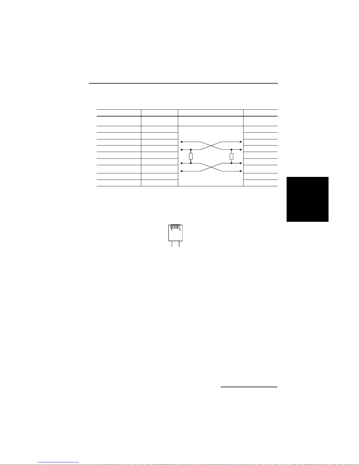
Dialogic® Diva® Karten Installationsanleitung
Pol- (Kontakt-) Belegung für 8-polige Verbindungen (Stecker und Buchsen):
TE NT
Pins auf RJ-45 Draht Signal Verdrahtung Draht Signal
1nicht verwendet
2nicht verwendet
3 2a TX + 1a TX +
4 1a RX + 2a RX +
51bRX - 2bRX 62bTX - 1bTX -
7nicht verwendet
8nicht verwendet
Widerstände
Abschlusswiderstände
100 Ohm, 5%
Hinweis: Pin 1 befindet sich links (siehe Abbildung unten), wenn Sie den
RJ-45 Stecker mit dem Kabel nach unten, den Pins zu Ihnen und der Lasche
DEUTSCH
von Ihnen weg gerichtet betrachten.
Anschließen ein e r Di a logic® Diva® PRI
Hinweis: Dialogic® Diva® PRI, außer Dialogic® Diva® V-xPRI PCIe HS/FS,
haben eine eingebaute CSU (Channel Service Unit), die sie vor
Beschädigungen durch Stromstöße schützt. Sie könne n jedoch auch eine
zusätzliche externe CSU benutzen, die Ihnen die Überprüfung Ihrer
ISDN-Leitung ermöglicht.
Verwende n Sie ein RJ-4 5 Kabel , um Ihre Div a PRI anzuschli eßen. Wie Sie das
Kabel benutzen, hängt davon ab, wie Sie Ihre Diva PRI einsetzen:
• RJ-45 zu RJ-45: zum Anschluss an eine ISDN-Leitung mit RJ-45 Buchse
und zum Einsatz als Master für eine TK-Anlage.
• RJ-45 zum offenen Kabelende: zur selbstdefinierten Leitungsbelegung
entsprechend dem verwendeten NT und zum Einsatz im Back-to-Back
Betrieb.
Seite 81
Page 82

DEUTSCH
Installation
Wenn die ISDN-Leitung mit einer RJ-45 Buchse installiert ist:
Verwenden Sie das Kabel mit RJ-4 5 Ste ckern auf beiden Seit en :
Diva PRI Signal RJ-45 Stecker
Pin 1 Rec ei ve + (RX +) Pin 1
Pin 2 Receive - (RX -) Pin 2
Pin 4 Transmit + (TX +) Pin 4
Pin 5 Transmit - (TX -) Pin 5
abgeschirmter Stecker völlig abgeschirmt abgeschirmter Stecker
Hinweis: Verwenden Sie für den E1 Modus mit 75 Ohm Impedanz einen
externen 75 Ohm Balun-Adapter. Sie können einen solchen Adapter in
Fachgeschäften erwerben.
®
Das Anschließen Ihrer Dialogic
• Für alle Diva PRI Karten, außer Dialogic
Diva® PRI Karte hängt vom Kartentyp ab:
®
Diva® V-8PRI PCIe FS Media
Boards, folgen Sie den nachfolgenden Anweisungen.
®
•Für Dialogic
Diva® V-8PRI PCIe FS Media Boards, folgen Sie den
Anweisungen auf Seite 84.
Schließen Sie Ihre Dialogic
®
Diva® PRI Karte (außer Diva V-8PRI PCIe
FS) wie hier dargestellt an das ISDN an:
1. Nehmen Sie ein ISDN-Kabel und
stecken Sie ein Ende des Kabels in
die Diva Karte.
ISDN-Anschlussbuchse, NT
bzw. CSU
Diva PRI
2. Stecken Sie das andere Ende des Kabels
in die ISDN-Anschlussbuchse oder die
CSU.
Hinweis für alle Dialogic® Diva® V-2PRI und V-4PRI:
Die Diva V-2PRI hat zwei Ports und die Diva V-4PRI hat vier Ports zum
Anschließen an vier separate ISDN-Primärmultiplexanschlüsse. Schließen Sie
vier RJ-45 Kabel an, wie in der Abbildung oben beschrieben. Sie können
beliebige Ports verwenden, müssen in der Regel aber die Port-Nummer
während der Softwarekonfiguration angeben. Sehen Sie auf der nächsten
Seite die P ortnummern. In der A bbildung weist der Kartensteckve rbinder nach
unten.
Seite 82
Page 83
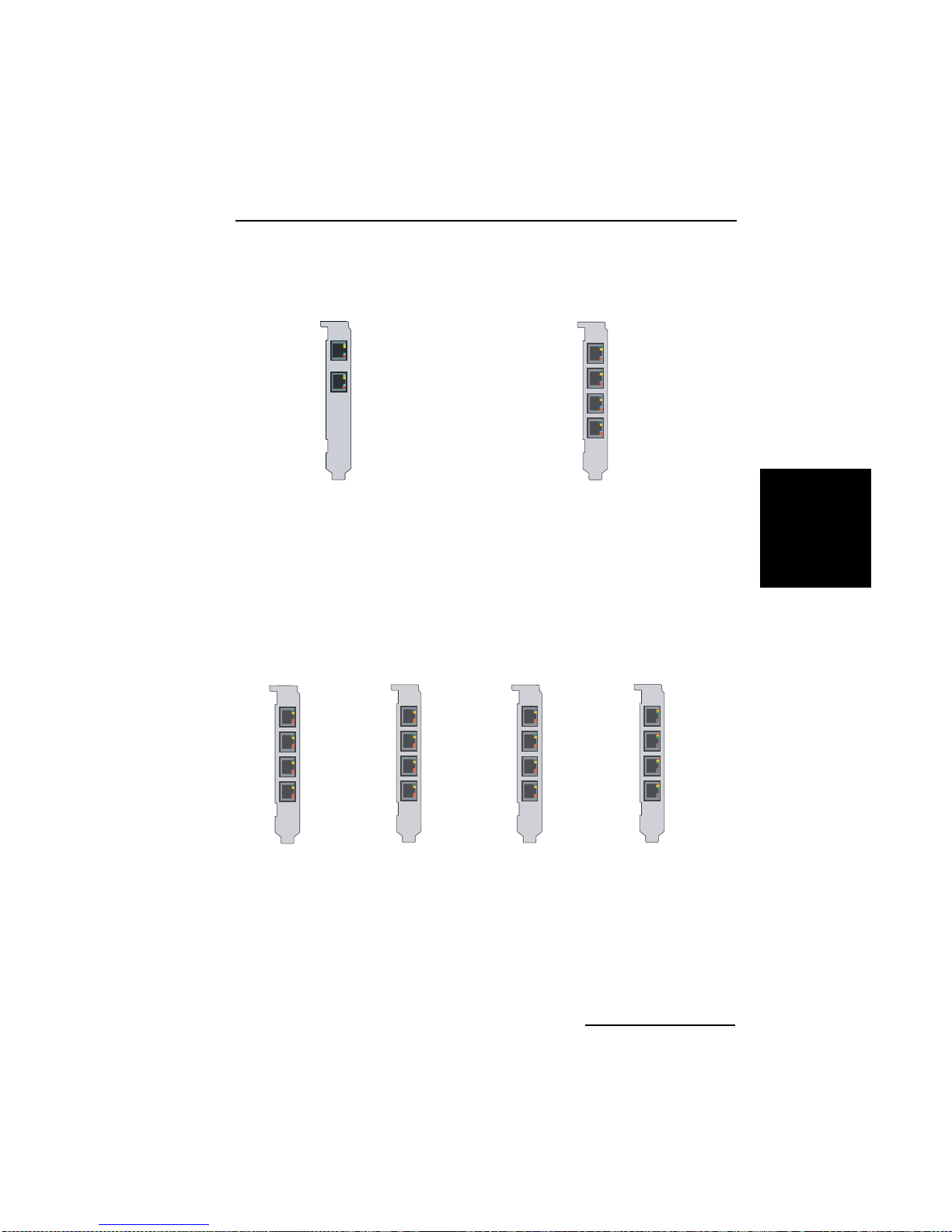
Dialogic® Diva® Karten Installationsanleitung
Diva V-2PRI
Port 1
Port 2
Diva V-4PRI
Port 1
Port 2
Port 3
Port 4
Hinweis für Dialogic® Diva® V-1PRI PCIe HS, Diva V-2PRI PCIe HS,
Diva V-4PRI PCIe HS und Diva V-4PRI PCIe FS:
Die Diva V-xPRI PCIe HS und V-4PRI PCIe FS haben vier Ports. Das "x" bzw.
die "4" im Namen steht für die aktivierten Ports, d. h. 1 Port ist auf der
Diva V-1PRI HS aktiviert, 2 auf der Diva V-2PRI HS und 4 auf der Diva V-4PRI
HS und Diva V-4PRI FS. Sie können nur die aktivierten Ports benutzen (siehe
Abbildung unten). In der Abbildung weist der Kartensteckverbinder nach
unten. In der Re gel müssen Sie die Port-Nummer während der
Softwarekonfiguration angeben.
Diva V-1PRI HS Diva V-2PRI HS
Port 1
Port 1
Port 2
Diva V-4PRI HS
Port 1
Port 2
Port 3
Port 4
Diva V-4PRI FS
Port 1
Port 2
Port 3
Port 4
DEUTSCH
Hinweis: Die Diva V-1PRI PCIe HS, V-2PRI PCIe HS, V-4PRI PCIe HS und
V-4PRI PCIe FS haben keine eingebaute CSU/DSU (Channel Service Unit/Data
Service Unit). Diese muss von einem Händler bezogen und extern
angeschlossen werden.
Seite 83
Page 84
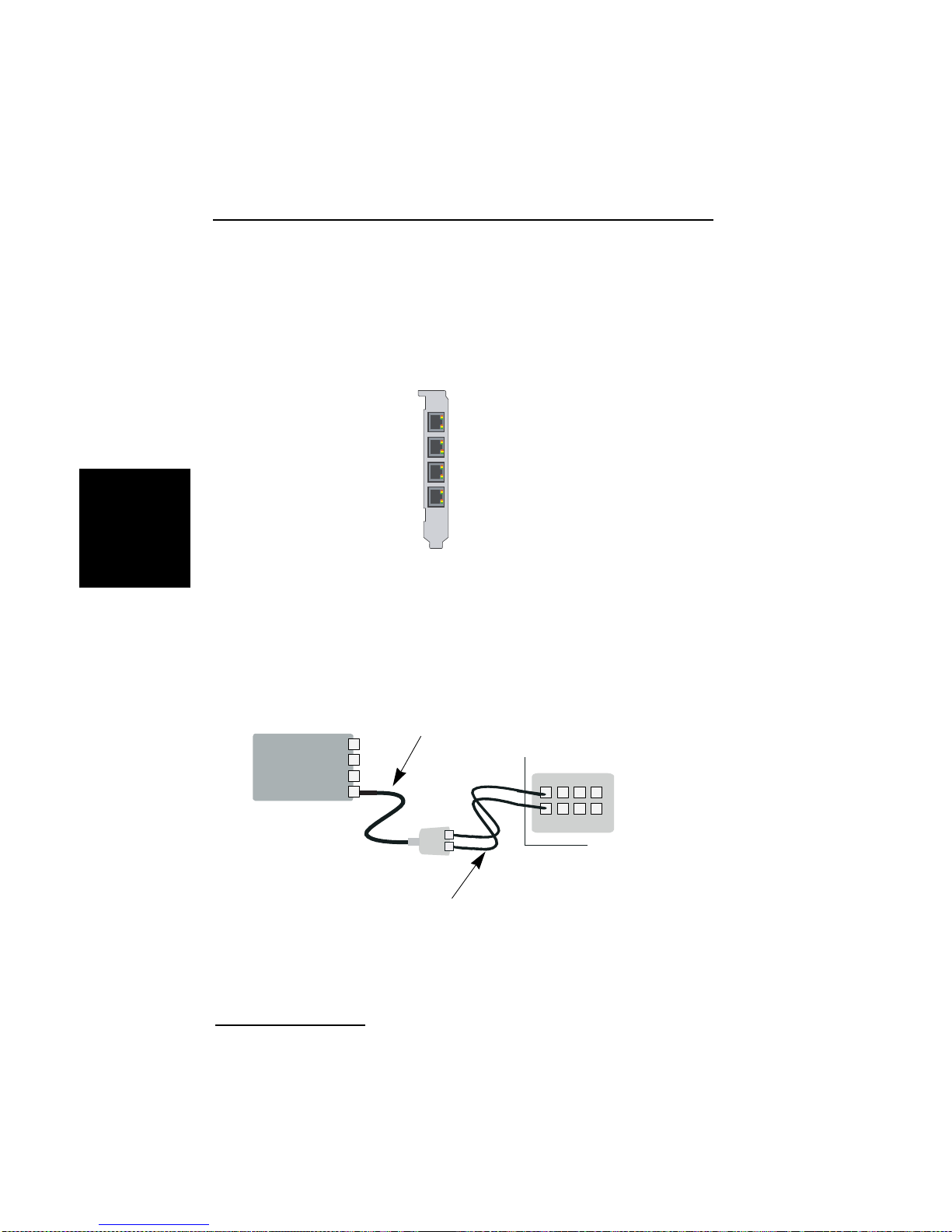
DEUTSCH
Installation
Dialogic® Diva® V-8PRI PCIe FS
Die Diva V-8PRI PCIe FS hat vier RJ-45 Ports zum Anschließen an vier RJ-45
Adapter , die je zwei RJ-45 Buchsen haben. Somit repräsentiert jeder Port auf
der Diva Karte zwei Ports an der ISDN-Anschlussb uchse, NT oder CSU. Sie
können beliebige Ports verwenden, müssen in der Regel aber die Port-Nummer
während der Softwarekonfiguration angeben. Sehen Sie unten die
Port-Nummern. In der Abbildung weist der Kartensteckverbinder nach unten.
Port 1 und Port 5
Port 2 und Port 6
Port 3 und Port 7
Port 4 und Port 8
Hinweis: Die Diva V-8PRI PCIe FS hat keine eingebaute CSU/DSU (Channel
Service Unit/Data S ervice Unit). Diese muss von ein em Händler bezog en und
extern angeschlossen werden.
Schließen Sie Ihre Diva V-8PRI PCIe FS wie hier dargestellt an das
ISDN an:
1. Nehmen Sie die vier mitgelieferten Kabel mit
Dual-Adapter und stecken Sie die RJ-45 Stecker
in die Diva V-8PRI PCIe FS.
Diva V-8PRI
PCIe FS
2. Nehmen Sie die acht
mitgelieferten Kabel und stecken
die RJ-45 Stecker in den
Dual-Adapter.
Wobei Buchse „A“ den Ports 1,2,3
und 4 entspricht und Bu chse „B“
den Ports 5,6,7 und 8.
Seite 84
ISDN-Anschlussbuchse, NT
bzw. CSU
3. Stecken Sie das andere Ende
der Kabel in die ISDNAnschlussbuchse oder die CSU.
Page 85
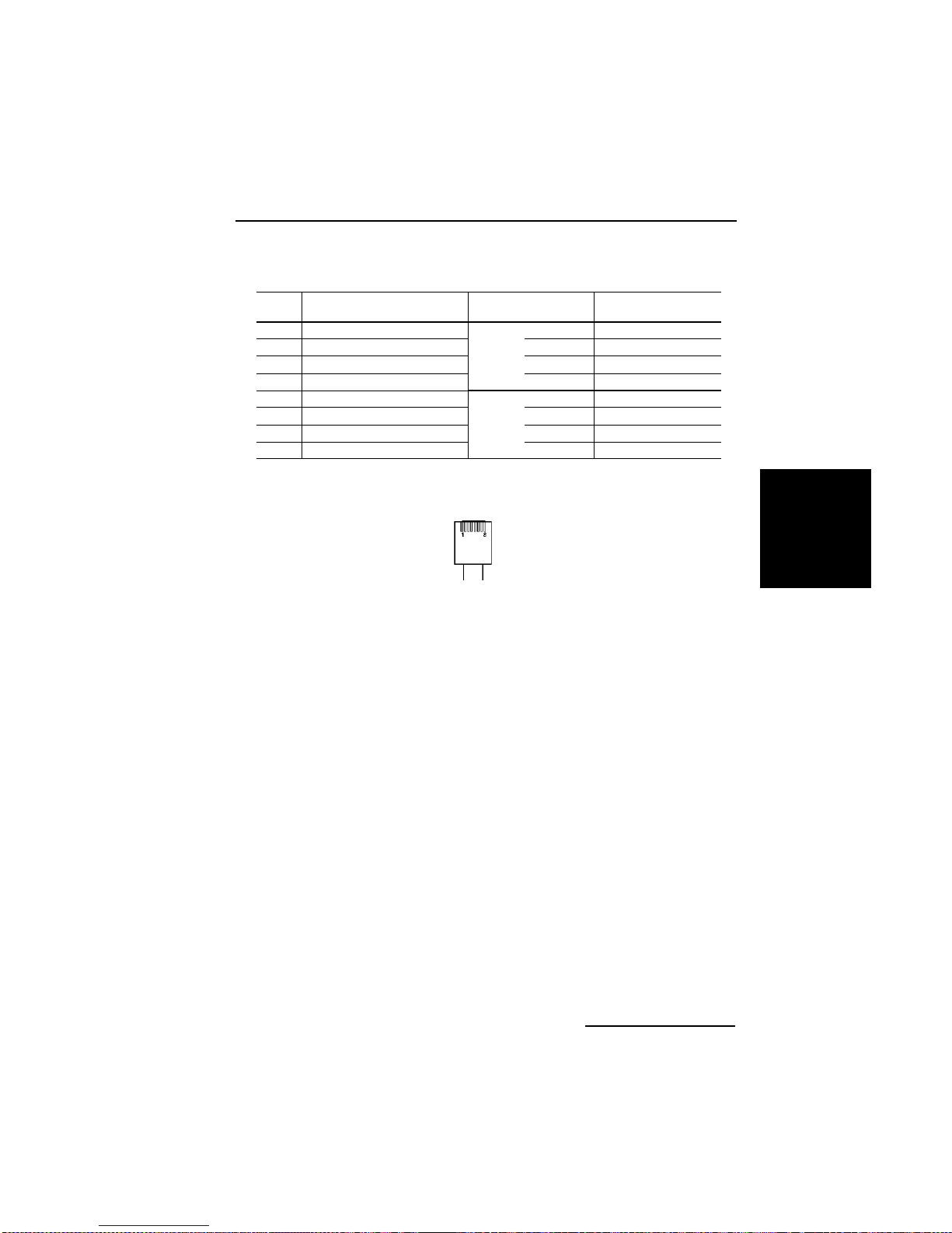
Dialogic® Diva® Karten Installationsanleitung
Verwenden Sie das Kabel mit Dual-Adap te r:
RJ45 Signal Dual-Adapter mit
Pin 1 Receive + (RX +) (Port A)
Pin 2 Receive - (RX -) (Port A) Pin 2 Receive - (RX -)
Pin 3 Receive + (RX +) (Port B) Pin 4 Transmit + (TX +)
Pin 4 Transmit + (TX +) (Port A) Pin 5 Transmit - (TX -)
Pin 5 Transmit - (TX -) (Port A)
Pin 6 Receive - (RX -) (Port B) Pin 2 Receive - (RX -)
Pin 7 Transmit + (TX +) (Port B) Pin 4 Tr ansmit + (TX +)
Pin 8 Transmit - (TX -) (Port B) Pin 5 Transmit - (TX -)
RJ45 Buchsen
Pin 1 Receive + (RX +)
Port A
Pin 1 Receive + (RX +)
Port B
Signal
Hinweis: Pin 1 befindet sich links (siehe Abbildung unten), wenn Sie den
RJ-45 Stecker mit dem Kabel nach unten, den Pins zu Ihnen und der Lasche
von Ihnen weg gerichtet betrachten.
®
Wenn die Dialogic
Die Dialogic
Diva® Karte als NT an eine TK-Anlage angeschlos sen wird:
®
Diva® System Release Software bietet die Möglichkeit, Diva
Karten als Netzabschluss (NT) einzusetzen. Dies ermöglicht den Einsatz von
Diva PRI als Master bei der Kopplung von TK-Anlagen z. B. mit dem Q-Sig
Protokoll.
Konfigurieren Sie die Diva Karte als Netzabschluss, wenn Sie die Diva Karte
an eine TK-Anlage anschließen, die als Endgerät (TE) agiert und daher einen
Netzabschluss zum Gene rier en der Taktung erfordert. Schl ießen Si e die Div a
Karte an die TK -Anlage an, wie im Diagramm auf Seite 86 dargestellt. Nehmen
Sie hierzu die entsprechende Anschlussbel egung an der TK-Anlage vor.
Wenn der NT offene Drahtanschlüsse benutzt:
In einigen Fällen müssen Sie Ihre Diva Karte an einen NT mit offenen
Verbindungen anschließen. Die Sende- (TX) und Empfangsleitungen (RX) sind
durch die Farbe der Leitungen gekennzeichnet; Sendeleitungen sind blau und
weiß-blau, Empfangsleitungen sind orange und weiß-orange.
DEUTSCH
Seite 85
Page 86

DEUTSCH
Installation
Verwenden Sie das ISDN-Kabel mit offenen Kabelenden:
Diva PRI Signal Offene Enden
Pin 1 Receive + (RX +) weiß-orange
Pin 2 Receive - (RX -) orange
Pin 4 Transmit + (TX +) blau
Pin 5 T r ansmit - (TX -) weiß-blau
abgeschirmter Stecker völlig abgeschirmt Abschirmung
Stellen Sie sicher, dass die Se ndeleitungen Ihrer Diva PRI an die
Empfangsanschlüsse des NTs und die Empfangsleitungen Ihrer Diva PR I an
die Sendea n s chlüsse des NTs angeschlo s se n werden.
Hinweis: Wenn Ihre Diva PRI nicht richtig am ISDN angeschlossen ist,
leuchtet sowohl am NT als auch in der Vermittlungsstelle der zuständigen
T elefongesell schaft eine Sc hicht 1 W arnlampe auf . W enn Sie eine ex terne CSU
verwenden, leuchtet auch eine Warnlampe an der CSU auf. Die Leitung wird
daraufhin möglicherweise von der Telefongesellschaft deaktiviert und muss
manuell wieder von de r Telefon gesellschaft aktiviert werden. Zu diesem Zweck
sollten Sie die St örungsstelle der zuständi gen T elefongesells chaft informieren.
®
Wenn die Dialogic
Die Dialogic
Diva
®
®
Karten als Netzabschl uss (NT) einzusetzen. Dies ermöglic ht Ihnen, zwei
Diva® PRI im Back-to-Back Betrieb eingesetzt wird:
Diva® System Releas e Software bietet die Möglichk eit, Dialogic®
Diva Karten im Back-to-Back Betrieb zu verwenden. Hierzu konfigurieren Sie
eine Diva Karte als Netzabschluss (NT) und die andere als Endgerät (TE).
Verbi nden Sie die Diva Karten mit eine m gekreuzten Kabel. Sie können ein
solches Kabel herstellen, indem Sie ein RJ-45-Kabel mit offenen Kabelenden
benutzen und das offene Ende entsprechend der Pin-Belegu ng für den
NT-Modus terminieren, wie in der folg enden Tabelle dargestellt:
Pins auf dem RJ-45 Signal
1 RX + RX +
2RX - RX 3nicht verwendet
4 TX + TX +
5TX - TX -
6nicht verwendet
7nicht verwendet
8nicht verwendet
Seite 86
TE NT
Verdrahtung
Signal
Page 87

Dialogic® Diva® Karten Installationsanleitung
Hinweis: Pin 1 befindet sich links (siehe Abbildung unten), wenn Sie den
RJ-45 Stecker mit dem Kabel nach unten, den Pins zu Ihnen und der Lasche
von Ihnen weg gerichtet betrachten.
Anschließen ein e r Di a logic® Diva® Analog
Verwende n Sie die mit geliefert en Kab el, um Ihre Div a Analog anzus chließen .
Das Anschließen der Diva Analog hängt vom Kartentyp ab:
®
• Wenn Sie eine Dialogic
nachfolgenden Anweisungen.
• Wenn Sie eine Dialogic
Anweisunge n a uf Seite 88.
• Wenn Sie eine Dialogic
Anweisunge n a uf Seite 90.
Wichtig: Benutzen Sie nur Kabel mit mindestens Nr. 26 AWG (American
Wire Gauge).
®
Dialogic
Diva® Analog-2:
Die Diva Analog-2 hat zwei RJ-11 Ports zum Anschließen an zwei sepa rate
Analoganschlüsse. Si e können beliebige Ports ver wenden, müssen in der Regel
aber die Port-Nummer während der Softwarekonfiguration angeben. Sehen
Sie unten die Port-Nummern. In der Abbildung weist der Kartensteckverbinder
nach unten.
Diva® Analog-2 anschlie ße n , fo lge n Sie den
®
Diva® Analog-4 anschlie ße n , fo lge n Sie den
®
Diva® Analog-8 anschlie ße n , fo lge n Sie den
DEUTSCH
Port 1
Port 2
Seite 87
Page 88
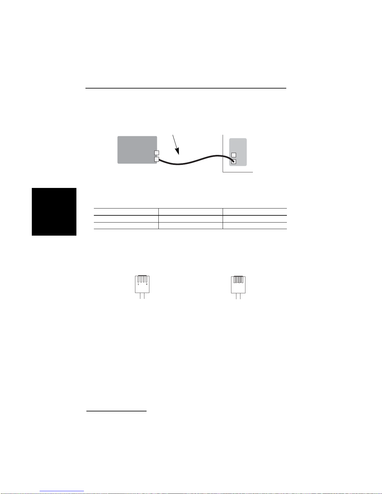
DEUTSCH
Installation
Schließen Sie di e Diva Analog-2 wie folgt an:
1. Nehmen Sie die zwei mitgelieferten
Kabel und stecken Sie die RJ-10
Stecker in die Ports der Diva
Analogkarte.
Diva Analog
2. Stecken Sie die RJ-11 Stecker in
die TAE-Buchsen oder in die
Telefonanlage.
TAE-Anschlussbuchsen
oder Telefonanlage
Kontaktbelegung (Stecker und Buchsen):
RJ-10 Signal RJ-11
Pin 2 Ring Pin 3
Pin 3 Tip Pin 4
Hinweis: Pin 1 befindet sich links (siehe Abbildung unten), wenn Sie den
RJ-10 oder RJ-11 Stecker mit dem Kabel nach unten, den Pins zu Ihnen und
der Lasche von Ihnen weg gerichtet betrachten.
RJ-10 Stecker RJ-11 Stecker
6
1
®
Dialogic
Diva® Analog-4:
Die Diva Analog-4 hat vier RJ-11 Ports zum Anschließen an vier separate
Analoganschlüsse. Sie können beliebige Ports verwenden, müssen in der Regel
aber die Port-Nummer während der Softwarekonfiguration angeben. Sehen
Sie auf der nächste n Se it e die Port-Num m e rn. In de r Ab bi ldung weist der
Kartensteckverbinder nach unten.
Seite 88
Page 89
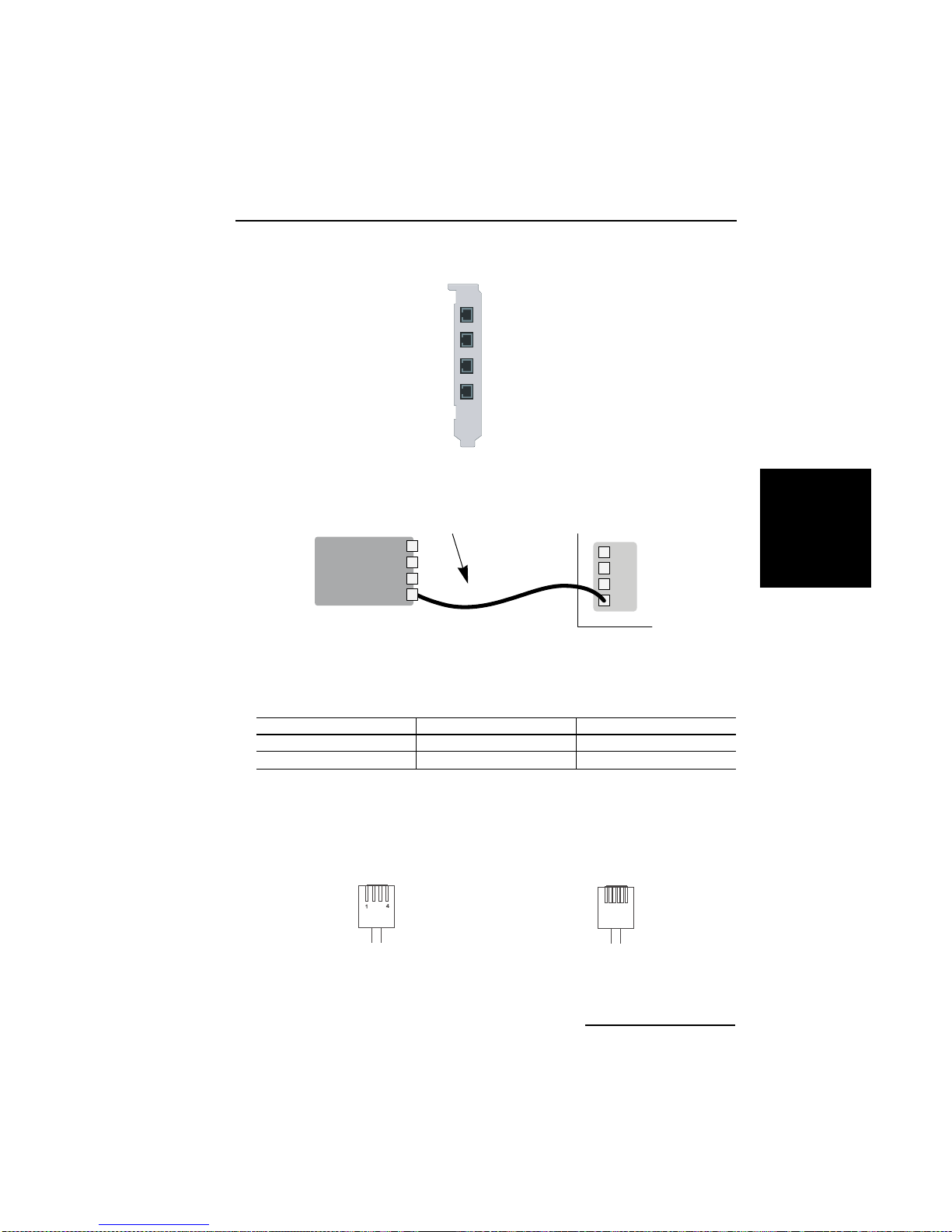
Dialogic® Diva® Karten Installationsanleitung
Port 1
Port 2
Port 3
Port 4
Schließen Sie die Dialogic® Diva® Analog-4 wie folgt an:
1. Nehmen Sie die vier mitgelieferten
Kabel und stecken Sie die RJ-10
Stecker in die Ports der Diva
Analogkarte.
TAE-Anschlussbuchsen
oder Telefonanlage
Diva Analog
2. Stecken Sie die RJ-11 Stecker in
die TAE-Buchsen oder in die
Telefonanlage.
Kontaktbelegung (Stecker und Buchsen):
RJ-10 Signal RJ-11
Pin 2 Ring Pin 3
Pin 3 Tip Pin 4
Hinweis: Pin 1 befindet sich links (siehe Abbildung unten), wenn Sie den
RJ-10 oder RJ-11 Stecker mit dem Kabel nach unten, den Pins zu Ihnen und
der Lasche von Ihnen weg gerichtet betrachten.
RJ-10 Stecker RJ-11 Stecker
6
1
DEUTSCH
Seite 89
Page 90
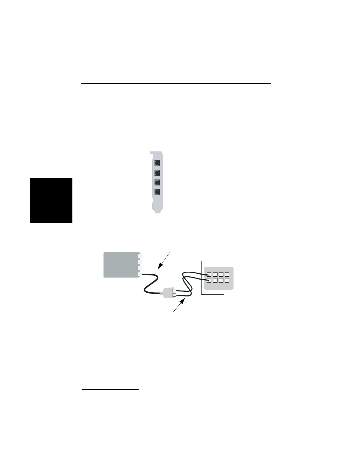
Installation
Dialogic® Diva® Analog-8:
Die Diva Analog-8 hat vier RJ-45 Ports zum Anschließen an vier RJ-45/RJ-10
Adapter , die je zwei RJ-10 Buchsen haben. Somit repräsentiert jeder Port auf
der Diva Karte zwei Ports an der TAE-Anschlussbuchse oder Telefonanlage.
Sie können belie b ige Ports verw e n de n, m ü s sen in de r Regel ab er die
Port-Nummer während der Softwarekonfiguration angeben. Sehen Sie unten
die Port-Nummern. In der Ab bildung weist de r Kartensteckverbinder nach
unten.
Port 1 und Port 2
Port 3 und Port 4
DEUTSCH
Schließen Sie Ihre Dialogic
1. Nehmen Sie die vi er mitgelief erten Kabel mit
Dual-Adapter und ste cken Sie die RJ-45 Ste cker
in die Diva Analogkarte.
Diva Analog
2. Nehmen Sie die acht
mitgelieferten Kabel und stecken die
RJ-10 Stecker in den Dual-Adapter.
Wobei Buchse „A“ de n Ports 1,3,5
und 7 entspricht und Buchse „B“ den
Ports 2,4,6 und 8.
Port 5 und Port 6
Port 7 und Port 8
®
Diva® Analog-8 wie folgt an:
TAE-Anschlussbuchsen
oder Telefonanlage
3. Stecken Sie die RJ-11 Stecker
in die TAE-Buchsen oder in
die Telefonanla ge.
Seite 90
Page 91
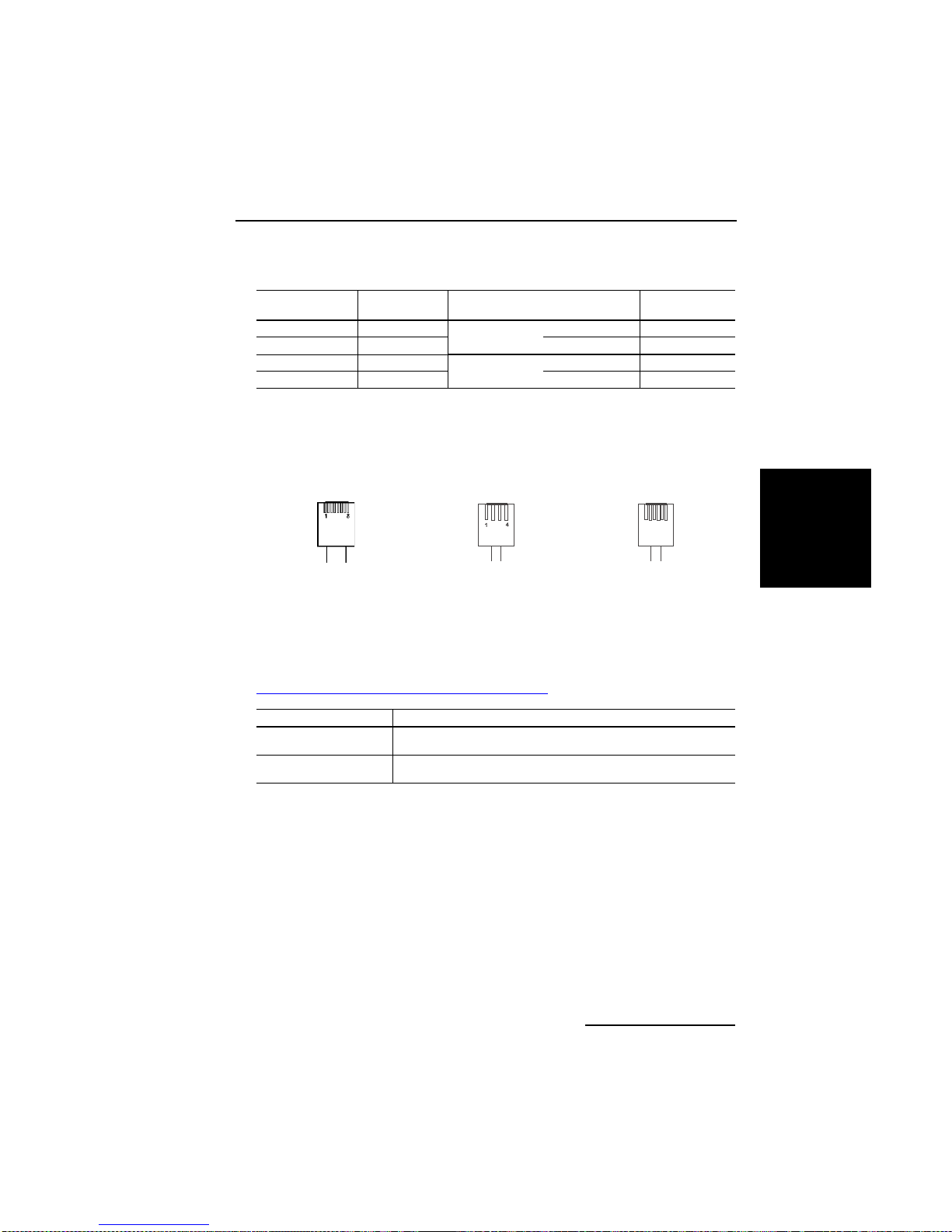
Dialogic® Diva® Karten Installationsanleitung
Kontaktbelegung (Stecker und Buchsen):
RJ-45 Signal Dual-Adapter mit RJ-10
Pin 1 Ring
Pin 2 Tip Pin 3 Pin 4
Pin 7 Tip
Pin 8 Ring Pin 2 Pin 3
Buchse A
Buchse B
Buchsen
Pin 2 Pin 3
Pin 3 Pin 4
RJ-11
Hinweis: Pin 1 befindet sich links (siehe Abbildung unten), wenn Sie den
RJ-45, RJ-10 oder RJ-11 Stecker mit dem Kabel nach unten, den Pins zu Ihnen
und der Lasche von Ihnen weg gerichtet betrachten.
RJ-45 Stecker RJ-10 Stecker RJ-11 Stecker
6
1
(C) Die Dialogic
Informationen zur Installation der Software für Ihre Dialogic
®
Diva® System Release Software installieren
®
Diva® Karte
finden Sie in der On lin e -Dokumentatio n, die mit den Softwaretrei be rn
mitgeliefert wi rd oder auf der Dialogic Internetseite unter
http://www.dialogic.com/manuals/default.htm
Betriebssystem Dokumentation
Alle Windows
Betriebssysteme
Linux Dialogic
®
Dialogic® Diva® System Release WIN Reference Guide
(englisch)
®
(englisch)
Diva® System Release LIN Reference Guide
verfügbar ist.
DEUTSCH
Seite 91
Page 92

Problembehandlung
Problembehandlung
Die folgenden Hinweise helfen bei der Diagnose und beim Beheben von
Fehlern, die mit d er Di alogi c
®
Diva® Karte oder der dazugehörigen Software
auftreten können. Reichen diese Hinweise zur Fehlerbehebung nicht aus,
finden Sie im Online Reference Guide (a uf En g lis c h) o de r in der On line -H i lfe
(auf Englisch) zur jeweiligen Software und auf der Dialogic Services & Support
Internetseite (siehe Seite 109) weitere Informationen.
Dialogic® Diva® Line Test (Anschlusstest)
(nur für Microsoft® Windows® Betriebssysteme)
®
Mit dem Diva Line Test Tool können Sie Ihre Dialogic
DEUTSCH
Analog- oder ISDN-Anschluss überprüfen.
Zum Öffnen des Diva Line Test Tools klicken Sie auf Start > Programme >
Dialogic Diva > Line Test.
Sie können folgende Tests durchführen:
• Line Check: Dieser Test überprüft, ob eine Ve rb indung zur Gegens telle
aufgebaut werden kann.
• Hardware Test: Dieser Test überprü ft di e Co n tr oller auf der Diva Karte.
• Telefon/Loop: Der Telefon-/Looptest führt einen Ruf zu einem anderen
Te lefon oder zum eigenen Anschluss durch .
• Call Transfer: Dieser Test führt Rufweiterleitungen durch. Dabei kann die
Art der Rufweiterle it un g au s ge w ä hlt we rd e n.
• Fax: Mit diesem Test können Sie Testfaxe senden oder empfangen.
Für weitere Infor mationen sehen Sie die Dialog ic
(DSLineTest.chm).
Diva® Karte und Ihren
®
Diva® Line Test Online-Hilfe
Seite 92
Page 93
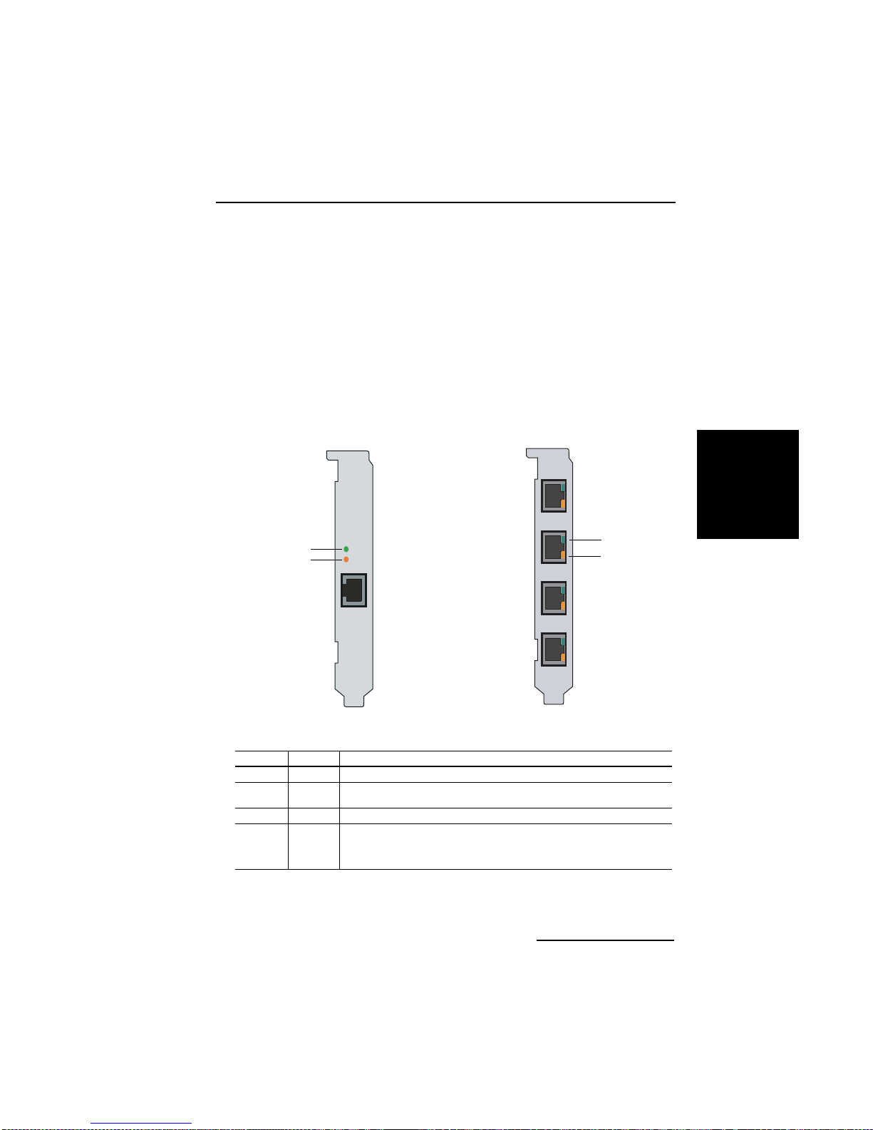
Dialogic® Diva® Karten Installationsanleitung
Status-LEDs
Dialogic® Diva® BRI und PRI Karten haben zwei oder vier Status-LEDs mit
unterschiedlichen Funktionen.
Dialogic® Diva® BRI und Diva UM-BRI
Die Diva BRI-CTI, Diva BRI-2FX, Diva BRI-2, Diva UM-BRI-2, Diva 4BRI-8 und
Diva UM-4BRI-8 haben zwei LEDs pro Port:
grün
orange
Diva BRI-CTI
Diva BRI-2FX
Diva UM-BRI-2
Diva BRI-2
Diva UM-4BRI-8
Diva 4BRI-8
Die untenstehende Tabelle beschreibt die Funktion der LEDs:
Farbe Status Beschreibung
grün aus Schicht 1 ist nicht aktiv.
an Schicht 1 ist aktiv. Die V erkabelung und die V erbindung zum ISDN
orange aus Schicht 2, der D-Kanal, ist nicht aktiv.
an Schicht 2, der D-Kanal, ist aktiv. In Europa ist der Status des
funktionieren fehlerfrei.
D-Kanals von der Protokollkonfiguration abhängig. Die LED
leuchtet entweder nur solange die Verbindung steht oder
dauerhaft.
DEUTSCH
grün
orange
Seite 93
Page 94
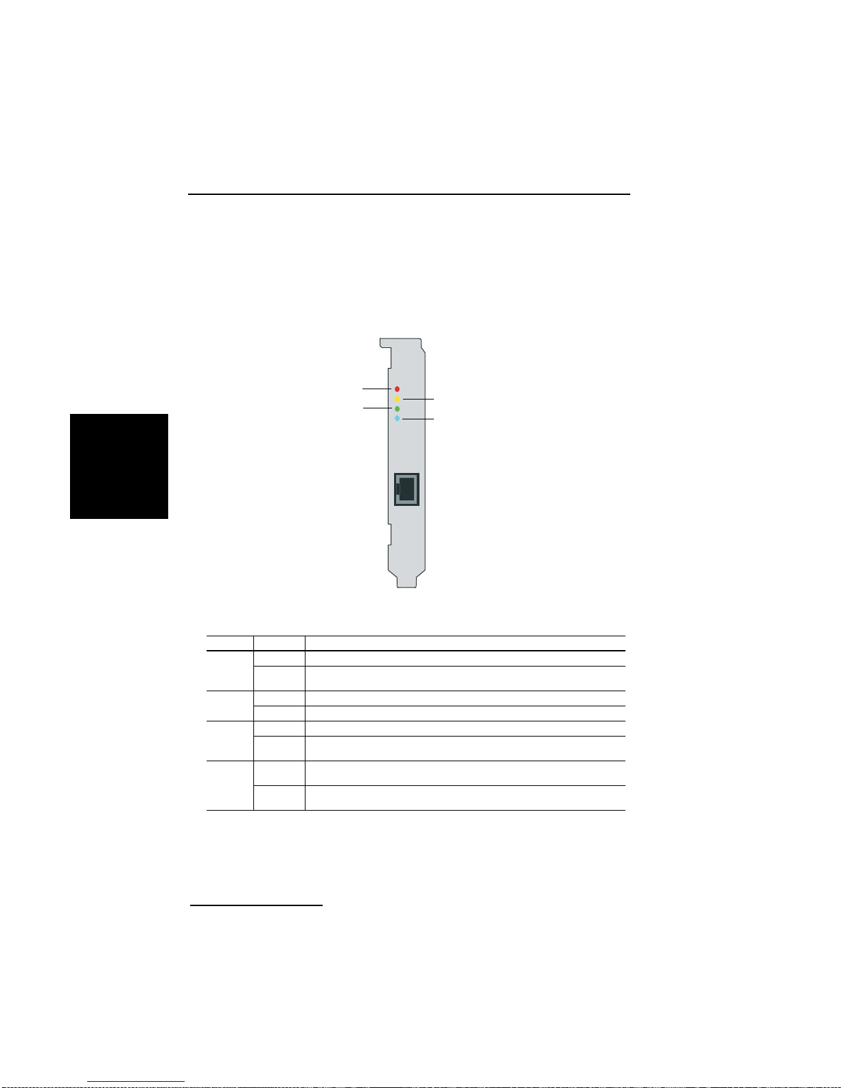
Problembehandlung
Dialogic® Diva® PRI, Diva V-PRI und Diva UM-PRI
Alle Diva PRI haben vier LEDs:
Diva PRI 3.0
Diva V-PRI
Diva UM-PRI
rot
grün
gelb
blau
DEUTSCH
Die untenstehende Tabelle beschreibt die Funktion jeder LED:
Farbe Status Beschreibung
gelb aus Normaler Betrieb.
an Die entfernte Station hat Synchronisationsprobleme. (remote
rot aus Normaler Betrieb.
an Der Empfänger nimmt kein Signal auf . ( loss of si gnal / red alar m)
blau aus Normaler Betrieb.
an Die empfangenen Rahmen sind nicht korrekt synchronisiert.
grün aus Schicht 2 ist nicht aktiv. Überprüfen Sie Ihre Schicht 2
an Schicht 2 ist aktiv. Wenn Ihre Dialogic
alarm / yellow alarm)
(alarm indication signal / blue alarm)
Konfiguration, d. h. D-Kanal-Protokoll, Telefonanlage, etc.
funktioniert, ist die Schicht 2 permanent aktiv.
®
Diva® PRI korrekt
Seite 94
Page 95
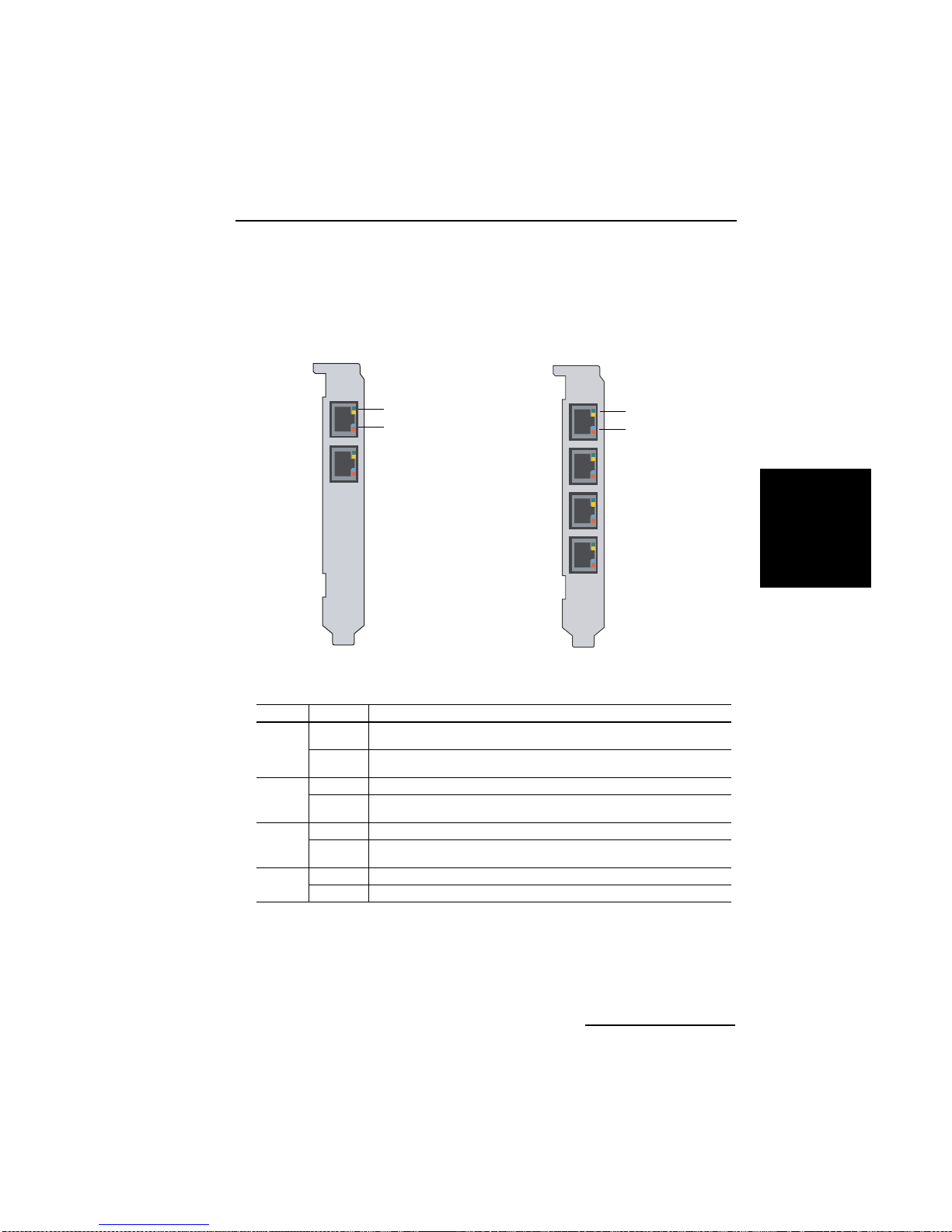
Dialogic® Diva® Karten Installationsanleitung
Dialogic® Diva® V-2PRI and Diva V-4PRI
Diva V-xPRI PCI haben pro Port zwei Multifunktions-LEDs pro Port:
Diva V-2PRI Diva V-4PRI
grün oder gelb
blau oder rot
grün oder gelb
blau oder rot
Die untenstehende Tabelle beschreibt die Funktion jeder LED:
Farbe Status Beschreibung
grün aus Schicht 2 ist nicht aktiv. Überprüfen Sie Ihre Schicht 2
an Schicht 2 ist aktiv. Wenn Ihre Dialogic
gelb aus Normaler Betrieb.
an Die entfernte Station hat Synchronisationsprobleme. (remote
blau aus Normaler Betrieb.
an Die empfangenen Rahmen sind nicht korrekt synchronisiert.
rot aus Normaler Betrieb.
an Der Empfänger nimmt kein Signal auf. (loss of signal / red alarm)
Konfiguration, d. h. D-Kanal -Prot okoll, Telefonanlage, etc.
funktioniert, ist die Schicht 2 permanent aktiv.
alarm / yellow alarm)
(alarm indication signal / blue alarm)
®
Diva® PRI korrekt
DEUTSCH
Seite 95
Page 96
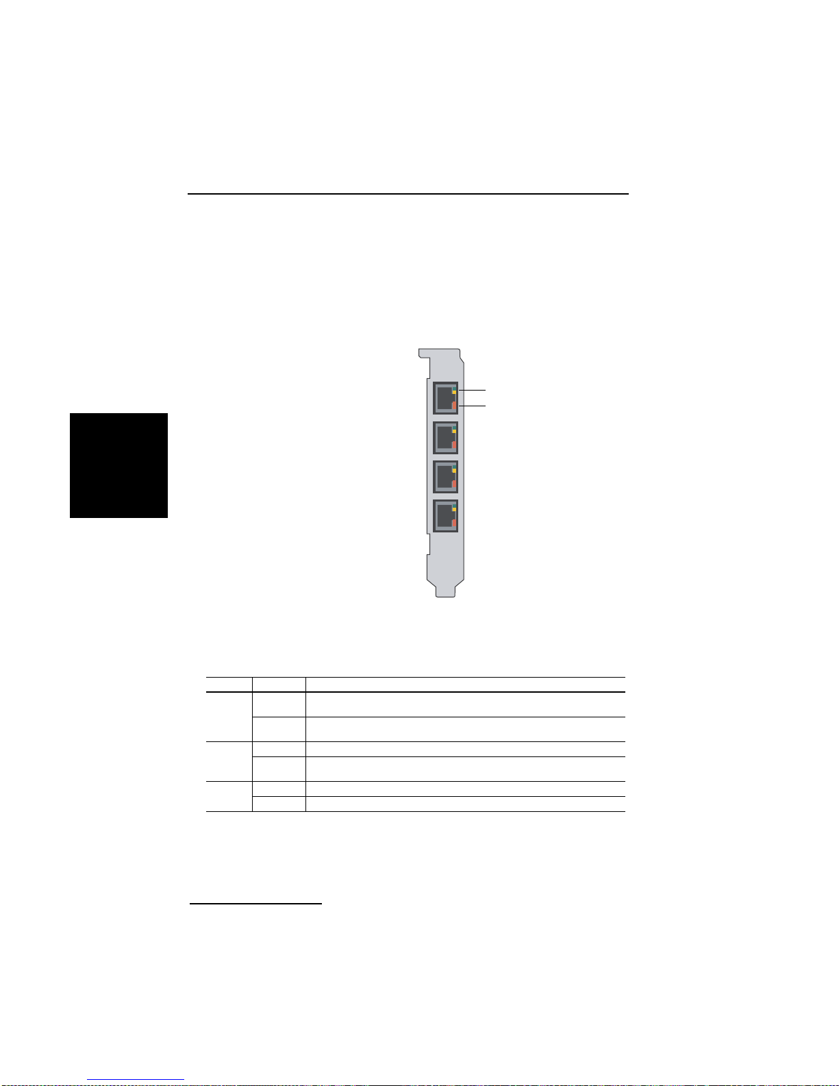
Problembehandlung
DEUTSCH
Dialogic® Diva® V-1PRI PCIe HS, V-2PRI PCIe HS und V-4PRI
PCIe HS
Diva V-xPRI PCIe haben Multifunktions-LEDs:
Diva V-1PRI PCIe HS
Diva V-2PRI PCIe HS
Diva V-4PRI PCIe HS
grün oder gelb
rot
Hinweis: Auf der Diva V-1PRI HS und Diva V-2PRI HS Karte sind nicht alle
Ports aktiviert. Weitere In f or ma t ionen dazu finden Sie auf Seite 81.
Die untenstehende Tabelle beschreibt die Funktion jeder LED:
Farbe Status Beschreibung
grün aus Schicht 2 ist nicht aktiv. Überprüfen Sie Ih re Schicht 2
an Schicht 2 ist aktiv. Wenn Ihre Dialogic
gelb aus Normaler Betrieb.
an Die entfernte Station hat Synchronisationsprobleme. (remote
rot aus Normaler Betrieb.
an Der Empfänger nimmt kein Signal auf . (loss o f signal / re d alarm)
Seite 96
Konfiguration, d. h. D-Kanal-Protokoll, Telefonanlage, etc.
funktioniert, ist die Schicht 2 permanent aktiv.
alarm / yellow alarm)
®
Diva® PRI korrekt
Page 97
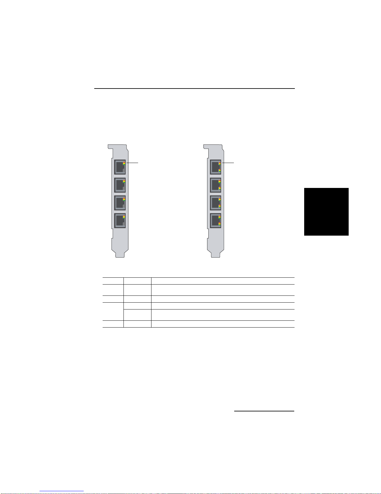
Dialogic® Diva® Karten Installationsanleitung
Dialogic® Diva® V-4PRI PCIe FS und V-8PRI PCIe HS
Diva V-xPRI PCIe FS haben Multifunktions-LEDs:
Diva V-4PRI PCIe FS Diva V-8PRI PCIe FS
rot, gelb oder grün rot, gelb oder grün
DEUTSCH
Die untenstehende Tabelle beschreibt die Funktion jeder LED:
Farbe Status Beschreibung
Alle
Farben
grün an Carries Sense (normale fehlerfreie Funktion)
gelb an Yellow alarm
rot an Red alarm
aus Software hat sich nicht initialisiert.
langsames
blinken
Blue alarm
Seite 97
Page 98

Technische Daten
Technische Daten
Umgebungsbedingungen:
• Betriebst em peratur: 10°C bis 50° C
• Maximal zulässige Spannungsschwankung: gemäß der entspreche nden
PCI Spezifikation (PCI/PCIe)
Diva UM-BRI-2
Diva BRI-2
Busformat PCI (3,3/5,0 V)
Prozessor 32 Bit RISC CPU, 100 MHz
DEUTSCH
Speicher auf der Karte 8 MB SDRAM 16 MB SDRAM
IRQs (Interrupt Request
Level)
I/O-Basisadressen (hex)
Gemeinsamer Speicher 8 MB 16 MB (Speicher)
DSPs 2 ADSP 2185 8 ADSP 2185
Abmessungen in mm
(Länge x Höhe)
Platine 167,65 x 64,41 174,63 x 106,68
Low Profile Metallschiene 181,36 x 80,06
Metallschiene 180,96 x 120,88 187,84 x 126,37
Datenübertragungsrate
B-Kanäle 2 x 64 kBit/s 4 x 2 x 64 kBit/s
D-Kanäle 1 x 16 kBit/s 4 x 16 kBit/s
Plug&Play
Stromsparmodus
Anschlussbuchsen 1 x RJ-45 (ISDN S
Anschlussart ISDN S
Stromverbrauch 0,33 A @ +5 V typ. 0,58 A @ +5 V typ.
Vom PC BIOS zugewi esen
) 4 x RJ-45 (ISDN S0)
-Anschluss 4 parallele S0-Anschlüsse
0
0
Diva UM-4BRI-8
Diva 4BRI-8
ja
Seite 98
Page 99

Dialogic® Diva® Karten Installationsanleitung
Diva UM-BRI-2 PCIe
Diva BRI-2 PCIe
Diva UM-4BRI-8 PCIe
Diva 4BRI-8 PCIe
Busformat PCIe 1.0a x1 Lane
Prozessor 32 Bit RISC CPU, 100 MHz
Speicher auf der Karte 64 MB SDRAM
IRQs (Interrupt Request
Level)
Vom PC BIOS zugewi esen
I/O-Basisadressen (hex)
Gemeinsamer Speicher 8 MB 16 MB (Speicher)
DSPs 2 ADSP 2185 8 ADSP 2185
Abmessungen in mm
(Länge x Höhe)
Platine 167,65 x 68,90 167,65 x 111,15
Low Profile Metallschiene 181,36 x 80,06
Metallschiene 180,96 x 120,88 180,96 x 126,31
Datenübertragungsrate
B-Kanäle 2 x 64 kBit/s 4 x 2 x 64 kBit/s
D-Kanäle 1 x 16 kBit/s 4 x 16 kBit/s
Plug&Play
Stromsparmodus
Anschlussbuchsen 1 x RJ-45 (ISDN S
Anschlussart ISDN S
Stromverbrauch 0,27 A @ 3,3 V typ.
0,17 A @ 12 V typ.
-Anschluss 4 parallele S0-Anschlüsse
0
ja
) 4 x RJ-45 (ISDN S0)
0
0,42 A @ 3,3 V typ.
0,19 A @ 12 V typ.
DEUTSCH
Seite 99
Page 100

DEUTSCH
Technische Daten
Diva BRI-CTI
Diva BRI-2FXI
Busformat PCI (3,3/5,0 V)
Prozessor 32 Bit RISC CPU, 133 MHz
Speicher auf der Karte 8 MB SDRAM
IRQs (Interrupt Request
Level)
I/O-Basisadressen (hex)
Gemeinsamer Speicher 8 MB
DSPs nein
Abmessungen in mm
(Länge x Höhe)
Platine 167,65 x 64,41
Low Profile Metallschiene 181,36 x 80,06
Metallschiene 180,96 x 120,88
Datenübertragungsrate
B-Kanäle 2 x 64 kBit/s
D-Kanal 1 x 16 kBit/s
Plug&Play
Stromsparmodus
Anschlussbuchse 1 x RJ-45 (ISDN S
Anschlussart ISDN S
Stromverbrauch 0,3 A @ +5 V typ.
Vom PC BIOS zugewi esen
ja
-Anschluss
0
)
0
Seite 100
 Loading...