


gate

Foreword |
2 |
|
Scope |
3 |
|
References |
4 |
|
Definitions |
5 |
|
1. |
Requirements for Safety |
7 |
2. |
Risk Assessment Process |
23 |
3. |
Commissioning Process |
25 |
4. |
New Gate & Barrier Compliance Legislation |
26 |
5. |
Existing Gate & Barrier Compliance Legislation |
31 |
Annex A – Risk Assessment Template |
37 |
|
Annex B – Certificate of compliance |
41 |
|
Annex C – Unsafe System & System Safety Unknown Notice |
43 |
|
Annex D – Declaration of Conformity & CE Plate |
45 |
|
Annex E – Example residual hazard control signs |
46 |
|
Annex F – Factory Production Control |
47 |
|
Annex G – Training and Competency |
49 |
|
Annex H – Complete new system non-compliance process |
50 |
|
Revision |
Description |
Date |
TS-011:2016 v1 |
First edition |
May 2016 |
Corrigendum 1 |
Typing error corrections to para 1 in Annex A, Table B2, B9.1 and B10.1 in Annex B |
Oct 2016 |
TS-011:2018 v3 |
Second edition, reformat & unify with TS 012:2018 |
Feb 2018 |
TS 011:2019 v4 |
Third edition, review and incorporation of EN 12453:2017 |
Mar 2019 |
|
|
|
|
|
|
|
|
|
|
|
|
1 1116:V4:04/19

This code of practice draws on applicable legislation, European standards, British standards and industry best practice to assist all those involved in the automated gate and barrier industry to meet their legal obligations by providing clear guidance on the design, manufacture, installation and maintenance of automated gates and barriers.
The objectives of this code of practice are to:
(i)explain the minimum safety standards for design, manufacture, installation, maintenance and operation of automated gate and barrier systems
(ii)provide guidance on the required level of user training and safety awareness
(iii)explain the minimum requirements for technical documentation
(iv)advise on a training and competency framework.
In 2011 the UK Health and Safety Executive lodged a formal objection to the package of standards covering automated gates and barriers in place at that time. After consultation and consideration, in July 2015 the European Commission issued a warning that the harmonised standard (EN 13241-1:2003+A1:2011) did not, by reference to the other standards in the package (primarily EN 12453:2000), achieve a level of safety that would comply with the Machinery Directive 2006/42/EC. Those who were relying on EN 12453:2000 and EN 12604:2000, by reference from EN 13241, were advised to review their risk assessment to ensure that their product did in fact meet the required level of safety for legal compliance.
BS EN 12453:2017 has now been published in the UK as an update to the original 2001 UK version but sadly has still not achieved the level of safety required for Machinery Directive compliance, despite the presence of an annex ZA that claims to confer compliance. A standard does not actually confer compliance with the Directive until it has been listed in the Official Journal.
https://ec.europa.eu/growth/single-market/european-standards/harmonised-standards/machinery_en
BS EN 12453:2017 contains a foreword, warning users not to rely on this standard (or by reference BS EN 12604:2017) for compliance with the Machinery Directive; HSE have also issued a warning.
http://www.hse.gov.uk/safetybulletins/revision-standards-powered-doors.htm
Where existing standards have been proven to be defective, or where industry experience or legal precedent has indicated there are common misinterpretations, this code of practice provides a workable method of mitigating the resulting risk.
As compliance with standards is technically in law mostly voluntary, the term “should” as opposed to “must” is used in many of the clauses. Users of this code are reminded however that product specific standards represent the legal minimum level of safety acceptable in law (variously the state-of-the-art or reasonable & practicable measures depending on legal jurisdiction) and hence where these standards are not followed, an equal or improved level of safety must be achieved – see 4.1.1. Account must also be taken of the fact that, in some areas, existing standards are not deemed adequate for legal compliance and hence additional steps must be taken; the advice given in this code strives to address these shortfalls. This is done to protect the safety and legal interests of users, service providers and owner groups.
Compliance with this code of practice cannot confer immunity from legal obligations.
Technical Specification TS 011:2019 2
This code of practice contains requirements and recommendations for the design, manufacture, installation, modification, repair and maintenance of automated gate and traffic barrier systems intended primarily for vehicles but which could also be accessed by persons.
This code of practice excludes the following:
(i)lock or dock gates (for boats)
(ii)lift doors
(iii)doors in vehicles
(iv)armoured doors (e.g. safe or strong room doors)
(v)doors/gates mainly for the retention of animals
(vi)theatre textile curtains
(vii)industrial doors (see DHF TS 012:2019)
(viii)domestic garage doors (see DHF TS 012:2019)
(ix)doors used exclusively for pedestrians (see EN 16005)
(x)railway crossing traffic barriers (contact Network Rail in the UK for guidance).
This code of practice does not cover in detail the requirements for design or manufacture of control panels, drive units or safety components, although reference is made to the minimum requirements and documentation required for supply and use of these components.
3 1116:V4:04/19

The latest versions of the following standards provide information which is supplementary to the requirements of this code of practice. Where referenced in this code of practice, compliance with the relevant elements of these standards is a requirement for compliance with this code.
For dated references, the latest edition of the publication referred to applies (including amendments).
BS 7671, Requirements for electrical installations, also known as the IET Wiring Regulations
ET 101, ETCI Rules for electrical Installations (Republic of Ireland)
EN 12978, Industrial, commercial and garage doors and gates – Safety devices for power operated doors and gates – Requirements and test methods
ISO 13849-1, Safety of machinery – Safety related parts of control systems - Part 1 General principles for design
BS 6375-1, Performance of windows and doors. Classification for weathertightness and guidance on selection and specification
EN 1991-1-4, Eurocode 1. Actions on structures. General actions. Wind actions
For companies undertaking the design and manufacture of mass produced or series production of automated gates or traffic barriers the current version of the following standards describe the state-of-the-art necessary for legal compliance, notwithstanding the points raised in the foreword in regard to current standards.
EN 13241:2003+A2:2016, Industrial, commercial and garage doors and gates – product standard - performance characteristics.
EN 12453:2017, Power operated industrial, commercial and garage doors and gates – safety in use.
EN 12604:2017, Industrial, commercial and garage doors and gates – mechanical aspects.
ISO 13857, Safety of machinery – Safety distances to prevent hazard zones being reached by upper and lower limbs.
EN 12635, Industrial, commercial and garage doors and gates – Installation and use instructions.
EN 60204-1, Safety of machinery – Electrical equipment of machines, general requirements.
Machinery Directive 2006/42/EC https://ec.europa.eu/docsroom/documents/9202/attachments/1/translations/en/renditions/native European Commission Guide to Machinery Directive compliance https://osha.europa.eu/en/legislation/guidelines/guide-application-machinery-directive-200642ec
Technical Specification TS 011:2019 4

Button, switch, key switch, handheld radio transmitter, radio transponder, digital keypad, intercom, ground loop, radar movement sensor or any other device used to generate or deliver a command to a powered gate or barrier system.
Company or person who assembles a powered gate or barrier from components and hence takes on the responsibilities of a “manufacturer” in regard to legal compliance.
A powered gate or barrier primarily intended for vehicular use, but which might also be encountered by persons in industrial, commercial, residential or domestic premises.
Document issued to a system manager certifying that the gate or barrier meets the requirements of this code of practice. Not to be confused with or replace a Declaration of Conformity (below).
A legally required document from a company or person responsible for legal compliance stating that the product to which it applies meets all relevant requirements of the Machinery Directive (see section 4) and all other European product safety Directives applicable to that product; when first placed on the market or put into service.
A legally required document from the manufacturer of a partly completed machine (PCM) to inform the assembler of the final machinery into which it will be incorporated that the PCM fulfils the requirements of all applicable European product safety Directives.
An alteration to an existing system that is so extensive that a new gate or barrier has been created and hence the need for CE marking or re-CE marking in accordance with the Machinery Directive. This does not occur where parts are replaced like for like but does occur where the way it operates has changed significantly.
Individual employed by an installation contractor to install, repair, maintain or modify gate or barrier systems.
Company or person responsible for the safe installation of a gate or barrier system.
Company or person responsible for the manufacture of a component or complete gate or barrier.
Company or person contracted to provider maintenance, modification or repair of an existing system.
An assembly which is almost machinery, but which cannot itself perform a specific application, an electric operator and control board is partly completed machinery.
Routine servicing of a system carried out on a regular basis, to ensure ongoing safety and reliability.
Repair, maintenance or modification carried out in response to the development of a fault.
5 1116:V4:04/19

The hazard that remains when the legal minimum “state-of-the-art” degree of safety has been achieved.
The process of identifying hazards and controlling, or checking that they are controlled, to legally acceptable levels.
A component which serves to fulfil a safety function and is independently placed on the market. The failure and/or malfunction of which endangers the safety of persons, and which is not necessary in order for the machinery to function, or for which normal components could be substituted in order for the machinery to function (albeit less safely).
A system in conformity with the requirements of this code.
The state-of-the-art is a concept required by recital 14 of the Machinery Directive. It is the level of safety required and described in current product specific standards and other readily available relevant documents. The state-of-the-art represents the minimum level of safety permitted by the Directive. It is by this means that the state-of-the-art can change due to advances in technology and as standards are updated without the need to edit the Directive.
Company or person owning, or in control of, or with legal responsibility for, a gate or barrier in service. The system manager has legal responsibilities to users or others who may encounter the system in use. The system manager is very often the client of the installation or maintenance contractor.
A notice issued to a system manager informing them that due to a lack of safe access, the safety of the gate or barrier system in question cannot be ascertained, and hence it is not known if it is safe to use or not.
A notice issued to a system manager informing them that the gate or barrier in question system has been assessed as being unsafe in accordance with this code of practice.
Anybody operating, using or passing by the gate or barrier system who may be affected by it.
Technical Specification TS 011:2019 6
This section is based on information gained from current and past standards; primarily EN 12453 and EN 12604. Where a requirement reflects a change that only applies to systems installed after a certain date, this is declared in the relevant clause. Overall, the requirements for safety in this section relate equally to new or existing gates & barriers.
Central to providing the required level of safety is the training, experience and competence of those involved; requirements for training and competency are outlined in Annex G of this code.
The system should be designed and specified to reflect the demands of the site and the needs of users and yet remain safe. Factors that should be considered are: a) environment (wind, rain, flood risk, dust, ultra violet, flora and fauna); b) location (sloping ground, emergency entry and egress, visibility and nature of traffic); c) duty cycle (how often the system will operate per hour/24-hour period); d) user vulnerability (vicinity to the public, young children, people with physical and sensory limitations or people with learning restrictions). The final specification should be compliant with this code, be drawn up as a design proposal and be agreed with the client.
A suitable and sufficient risk assessment should be conducted and recorded as evidence of compliance for: a) the design of a new gate or barrier; b) installation of complete gate or barrier supplied by a 3rd party; c) upon modification of an existing gate or barrier; d) and prior to taking on reactive or planned maintenance of a gate or barrier for the first time. The risk assessment should include the seven steps described in section 2 and be recorded and retained as evidence of compliance. Where the risk assessment is being conducted for the design of a new powered gate or barrier, it should include a list of Machinery Directive Essential Health and Safety Requirements complied with (see section 4).
Where the risk assessment for installation of a new CE marked gate or barrier, supplied by a third-party (see section 4), indicates that the gate or barrier does not achieve the state-of-the-art (the requirements for safety in this section), the installation contractor should refer to and apply the process described in Annex H.
Where the risk assessment of such a gate or barrier indicates that the state-of-the-art is achieved but residual hazards are present based on its local environment or use, the installation contractor should address them - see 1.5.11.
A certificate of compliance should be issued to the client on successful completion of a compliance assessment: a) upon completion of a modification of an existing gate or barrier; b) at take-over of a gate or barrier under maintenance contract; c) following a one-off repair of a gate or barrier not under a planned maintenance contract.
Where the compliance assessment of an existing gate or barrier indicates non-compliance with this code, an unsafe system notice (see Annex C.1) should be issued instead.
Where access to safety critical elements is not possible in safety, it cannot be ascertained if the gate or barrier is safe or not and hence a system safety unknown notice (see Annex C.2) should be issued instead.
Hazards are the things that could potentially cause harm. All gate and barrier systems possess hazards. Some hazards like structural failure, electric shock and crush at the leading edge are generic to all systems, other hazards are more system or site specific. The first step is always to identify and list all potential hazards present. Hazards do not represent what is wrong or deficient with a system, they are the things that could go wrong and hence need to be prevented or controlled. Installations should be designed to eliminate or reduce hazards wherever reasonably practicable rather than use sensitive devices to control hazards created by the design.
Hazards should be controlled by one of four main strategies:
(i)safe design (structural integrity, remove the hazard or make it inaccessible), 1st priority
(ii)human visual control (hold to run)
(iii)safe contact (limit the exerted force on people)
(iv)non-contact presence detection (ensure that hazardous movement cannot make contact with people).
7 1116:V4:04/19
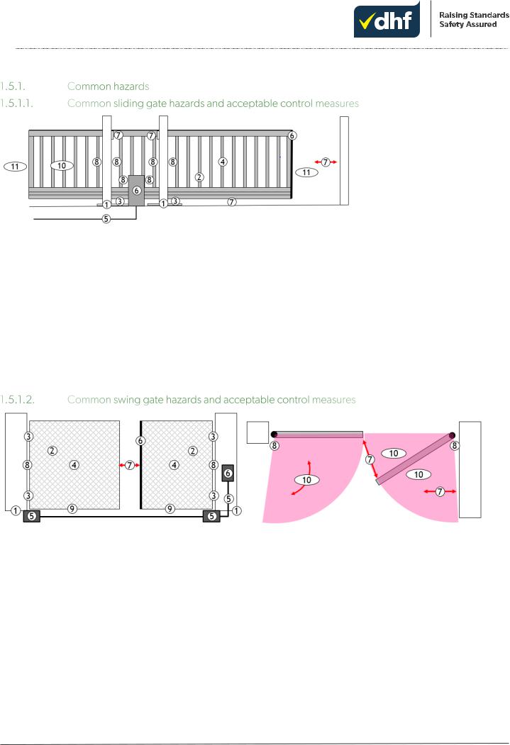
Other hazards commonly exist; all hazards must be identified and controlled in the same manner as those shown here.
1 |
Structural failure – supporting structures |
Provide adequate strength 1.5.2 |
|
2 |
Structural failure - leaf |
Provide adequate strength 1.5.2 |
|
3 |
Structural failure – guides, rolling gear & travel stops |
Provide adequate strength 1.5.2 |
|
4 |
Structural failure – wind load |
Provide adequate strength 1.5.2 |
|
5 |
Electrical – shock/fire |
Provide electrical safety 1.5.3 |
|
6 |
Control – faults in safety systems |
Provide control system integrity 1.5.3.11 & 12 |
|
7 |
Crush – within 500mm of a fixed object (open/close) |
Safety distance 1.5.4, hold to run 1.5.5, force limitation |
|
1.5.6 or presence detection 1.5.7 |
|||
|
|
||
8 |
Crush, shear & draw-in - at the supports & drive |
Enclosure 1.5.4, hold to run 1.5.5, safe edge 1.5.6or |
|
presence detection 1.5.7 |
|||
|
|
||
9 |
Crush - at guide rollers when below 2.5m |
Enclosure 1.5.4, hold to run 1.5.5, presence detection 1.5.7 |
|
10 |
Shear – through perimeter fence |
Enclosure 1.5.4, hold to run 1.5.5, presence detection 1.5.8 |
|
11 |
Impact – swept area |
Enclosure 1.5.4, hold to run 1.5.5, force limitation 1.5.6, |
|
presence detection 1.5.7 |
|||
|
|
Other hazards commonly exist; all hazards must be identified and controlled in the same manner as those shown here.
1 |
Structural failure – supporting structures |
Provide adequate strength 1.5.2 |
|
2 |
Structural failure - leaf |
Provide adequate strength 1.5.2 |
|
3 |
Structural failure – hinges, fixings & travel stops |
Provide adequate strength 1.5.2 |
|
4 |
Structural failure – wind load |
Provide adequate strength 1.5.2 |
|
5 |
Electrical – shock/fire |
Provide electrical safety 1.5.3 |
|
6 |
Control – faults in safety systems |
Provide control system integrity 1.5.3.11 & 12 |
|
7 |
Crush – within 500mm of a fixed object (open/close) |
Safety distance 1.5.4, hold to run 1.5.5, force limitation |
|
1.5.6 or presence detection 1.5.7 |
|||
|
|
||
8 |
Crush – hinge area |
Safety distance 1.5.4, flexible guard 1.5.4, hold to run 1.5.5, |
|
safe edge 1.5.6 or presence detection 1.5.7 |
|||
|
|
||
9 |
Crush – under gate |
Safety distance 1.5.4, hold to run 1.5.5, force limitation |
|
1.5.6, presence detection 1.5.7 |
|||
|
|
||
10 |
Impact – swept area |
Hold to run 1.5.5, force limitation 1.5.6, presence detection |
|
1.5.7 |
|||
|
|
Technical Specification TS 011:2019 8
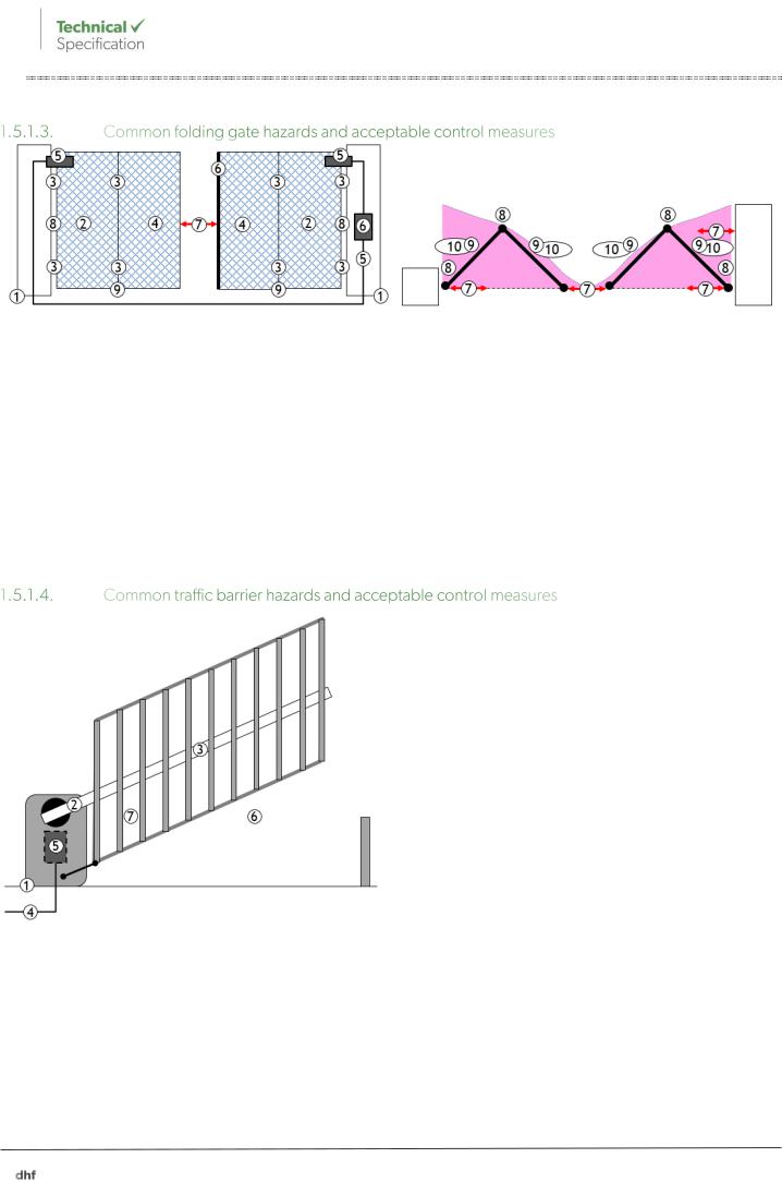
Other hazards commonly exist; all hazards must be identified and controlled in the same manner as those shown here.
1 |
Structural failure – supporting structures |
Provide adequate strength 1.5.2 |
|
2 |
Structural failure - leaf |
Provide adequate strength 1.5.2 |
|
3 |
Structural failure – hinges, fixings & travel stops |
Provide adequate strength 1.5.2 |
|
4 |
Structural failure – wind load |
Provide adequate strength 1.5.2 |
|
5 |
Electrical – shock/fire |
Provide electrical safety 1.5.3 |
|
6 |
Control – faults in safety systems |
Provide control system integrity 1.5.3.11 & 12 |
|
7 |
Crush – within 500mm of a fixed object (open/close) |
Safety distance 1.5.4, hold to run 1.5.5, force limitation |
|
1.5.6 or presence detection 1.5.7 |
|||
|
|
||
8 |
Crush – hinge area |
Safety distance 1.5.4, flexible guard 1.5.4, hold to run 1.5.5, |
|
safe edge 1.5.6 or presence detection 1.5.7 |
|||
|
|
||
9 |
Crush – under gate |
Safety distance 1.5.4, hold to run 1.5.5, force limitation |
|
1.5.6, presence detection 1.5.7 |
|||
|
|
||
10 |
Impact – swept area |
Hold to run 1.5.5, force limitation 1.5.6, presence detection |
|
1.5.8 |
|||
|
|
Other hazards commonly exist; all hazards must be identified and controlled in the same manner as those shown here.
1 |
Structural failure – supporting structures |
Provide adequate strength 1.5.2 |
|
2 |
Structural failure – arm, pivots and fixings |
Provide adequate strength 1.5.2 |
|
3 |
Structural failure – wind load |
Provide adequate strength 1.5.2 |
|
4 |
Electrical – shock/fire |
Provide electrical safety 1.5.3 |
|
5 |
Control – faults in safety systems |
Provide control system integrity 1.5.3.11 & 12 |
|
6 |
Crush – under the arm, or lower rail of a linkaged skirt |
Safety distance 1.5.4, hold to run 1.5.5, force limitation |
|
1.5.6 or presence detection 1.5.7 |
|||
|
|
||
7 |
Crush – at verticals and linkage of linked skirt only, |
Safety distance 1.5.4, flexible guard 1.5.4, hold to run 1.5.5, |
|
when below 2.5m |
safe edge 1.5.6 or presence detection 1.5.7 |
||
|
A free hanging, lightweight, gravity deployed skirt, does not normally present a significant crush hazard, but once the skirt has collapsed on contact, the barrier arm does!
9 1116:V4:04/19
The supporting structures, the leaf and any supporting elements should be designed (new systems) or assessed as being able (existing systems) to resist permanent deformity, ultimate structural failure or derailment in normal use, manual use or under foreseeable misuse. Any deformity that does occur in use should not be detrimental to safety or function.
The leaf, its supporting structure and any suspension elements should be designed (new systems) or assessed as capable of (existing systems) resisting falling down, collapsing or derailment in normal use and under foreseeable misuse conditions. The prescribed design safety factors (from EN 12604) are as follows:
(i)gate or barrier leaves, their supporting structures, suspension elements and fixings should be designed to withstand 2 x the total foreseeable load without permanent deformity
(ii)gate or barrier leaves, their supporting structures, suspension elements, fixings and travel stops, should be designed to withstand 3.5 x their total foreseeable load without ultimate structural failure.
As these are the design strength safety factors required, any on site testing at these levels could seriously damage a system hence, EN 12604 suggests that any non-destructive testing should be conducted at 1.1 x times ultimate theoretical maximum load. The safety factors quoted in (i) and (ii) above should be used as an indicator of the levels of overengineering necessary when assessing existing systems on site. The responsibility for initial assessment of any existing structures to support the load (new systems) is a job for an architect, principle designer or surveyor.
In particular, travel stops should prevent derailment (e.g. sliding gate) and suspension element failure (e.g. hinge failure) when used in manual or in windy conditions. Foreseeable misuse should be allowed for, which could mean a user moving the gate too fast in manual. It should be possible to secure the gate against wind action in the fully open and closed position, particularly when used in manual mode.
Swing and folding gate systems produced since 2018 (post publication of EN 12604:2017) should be protected against hinge failure such that if a hinge fails the gate will not drop nor move more than 300mm off its vertical axis. They should also be protected against being lifted more than 50% of their hinge pin length.
The effects of wind should be taken into account in the structural assessment. The system should remain safe when subject to foreseeable wind loadings. A system is not necessarily required to remain functional in high winds (although client/contractual requirements might require otherwise); the system should, however, remain safe. DHF offer the following advice in terms of likely maximum wind gust speeds:
(i)50 mph = Sheltered (inner city, built up areas with close buildings on all sides)
(ii)70 mph = Normal (normal urban environments)
(iii)100 mph = Exposed (open rural or hill top environments).
Information on predicting wind pressures on buildings can be found in BS 6375-1 and EN 1991-1-4. This is not an exact science, hence considerable margin for error should be applied where there is doubt.
Electricity at work legislation requires that work on electrical systems should be conducted by an electrically skilled person (e.g. qualified electrician) or by someone being instructed by an electrically skilled person (e.g. a trained installer following an installation manual and using safe isolation procedures). This does not make the installer an electrically skilled person, only skilled enough to execute a specific task.
The supply to the installation should be provided, tested and certified to comply with BS 7671/ET 101 as currently amended. Where an existing supply is utilised for an installation, evidence should be gained to demonstrate that it has been tested to ensure safety and compliance with BS 7671/ET 101 (e.g. client Electrical Installation Certificate or Periodic Inspection Report copy).
The control panel/motor manufacturer’s installation manual should take precedence in this regard. Where cable specifications and installation methods are prescribed in the manual, they should be followed. Continued over page.
Technical Specification TS 011:2019 10

Where no installation manual is available, the principles outlined in EN 60204-1 should be applied. Where the control panel/motor manufacturer prescribes the use of an RCD in the supply circuit one should be present upstream of the system.
A means to safely electrically isolate all poles (single phase = double pole & 3 phase = 4 pole) from the system for maintenance should be provided. Where an electrical isolator is remote from the gate or barrier (cannot been seen from the place of work), it should be possible to secure the isolator in the off position. Acceptable methods are multi pole switches or plug and socket combinations.
Safe isolation practices should be applied when working on electrical systems and warning notices posted as appropriate during the works.
The control panel/motor manufacturers installation manual should take precedence in this regard. Where the earthing requirements are prescribed in the manual, they should be followed. Where class 1 earthed conductive equipment (230/400v earthed) is present, all reachable extraneous conductive parts should have a continuity of no more than 0.5Ω to the supply earth terminal. Please note that many 24v electric operators are in fact 230v class 1 devices.
Where cables containing differing voltages share a conduit, all cables should have a voltage rating of the highest voltage present or the higher voltage cable should be surrounded by an earthed metallic screen, for example, steel wired armoured (SWA) cable or similar. The control panel manufacturer’s installation manual should take precedence in this regard. Many panel manufacturers do not allow conduit sharing at differing voltage bands.
Where communication or data cables share a conduit with power cables, clause 1.5.3.5 above should apply with the addition that the data cable should also be screened and earthed.
The control panel/motor manufacturer’s installation manual should take precedence in this regard. Where cable specifications and installation methods are prescribed in the manual, they should be followed. Cables should be rated for the voltage present and the maximum current possible; volts drop should be no more than 5% or within the control system supplier’s specification. Cable sizes should not deplete the earth fault loop resistance required by the circuit protective device.
Cables used to connect equipment that moves relative to fixed elements in normal use (e.g. rams) should be of multistranded conductors to IEC 60228 class 5 or 6 (multiple fine strand copper conductor, not SWA, etc).
Enclosures subject to external conditions should be at least IP54 (to prevent insect or slug ingress).
Enclosures and drive units used below ground should be at least IP67. As IP67 only covers temporary immersion, where IP67 components are used underground, effective drainage should be provided.
Enclosures containing exposed dangerous voltages (55v or more) should be marked with an appropriate dangerous voltage label and be openable only by means of key or tool.
All vulnerable cabling should be provided with mechanical protection by means of conduits, trunking or armouring. Vulnerable cabling is anything containing 55v or greater or anything that forms part of a control system; examples include photo beam cables, safe edge cables, non-contact presence detection cables, motor cables, encoder cables or access control device cables. All cables, trunking, conduits and enclosures should have adequate UV protection where they are subject to sunlight.
Manufacturers and assemblers should only use gate or barrier specific control panel and drive systems supplied with an appropriate Machinery Directive Declaration of Incorporation and installation manual. The supplied manual should be followed, a copy of both documents should be retained and kept in the technical file for the competed system.
11 1116:V4:04/19

Alternatively, if the manufacturer or assembler has built their own control system, they should type test the system for conformity with Machinery Directive Essential Health and Safety Requirements (EH&SR) 1.2 Safety and Reliability of Control Systems and; 1.5.1 Electrical Supply, and any other applicable EH&SRs in addition to all other applicable product safety Directives (see 4.1). This will include the Electromagnetic Compatibility Directive (electrical devices) and the Radio Equipment Directive (radio devices) where applicable. EN 12453:2017 and the relevant parts pf EN ISO 13849-1 describe the current requirements.
Manufacturers and assemblers should use gate or barrier specific safety devices (EN 12978 compliant) supplied with an appropriate Machinery Directive Declaration of Conformity and follow the supplied installation manual; a copy or the original of both documents should be retained and kept in the technical file.
The system connecting safe edge and non-contact presence detection devices should be fully compatible with the control system they are connected to such that, as installed, they conform to category 2 or 3. The circuit should be either protected from short circuit faults by a control panel derived category 2 test of the circuit at least once in every cycle, or for some category 3 devices not protected from short circuit faults, by means of:
(i)oversized and robust conductors, and
(ii)the use of short as possible cable routing, and
(iii)the use of crimped, feruled or tinned conductor ends to prevent stray strands.
Wherever reasonably practicable, the device should be placed within the control panel, or failing that be connected via armoured cable or cable in conduit.
Systems produced after 2018 (since publication of EN 12453:2017) are required to have all safety related parts of the control system in conformity with EN 13849-1 at minimum performance level C through the entire control system from any switch or sensing element to the motor terminals or be in full conformity with EN 60335-1 and EN 60335-2-103; this should include any wicket gate stop switch.
Limit switch, safe edge or non-contact presence detection devices will additionally need to achieve at least category 2 as installed and prevent further movement by at least the end of the current open/close cycle in the event of a fault.
Where a wicket gate is fitted in a powered gate, movement of the main gate should be prevented whenever the wicket gate is not in a safe position; devices and wiring used to achieve this should only fail to a safe condition.
All hazards related to moving parts should be eliminated or controlled up to a height of 2.5m above ground level, or any other permanent access level, e.g. stairway, mezzanine floor or control cabinet. Hazards that are not reachable by being out of reach do not need additional control measures.
The gap between fixed verticals in the leaf should be assessed in terms of the likely effect and consequences of various body parts being inserted. Particular care should be taken where sharp points exist between bars at lower levels. Where children below the age of 5 are present BS 6180 prescribes a gap of less than 100mm for fixed railings and balustrades, but this cannot be universally applied as either safe or unsafe for a moving gate leaf.
Various minimum safety distances exist (derived from EN 349 & EN 12453) to prevent injury to differing body parts.
Technical Specification TS 011:2019 12
Crush hazard |
|
Draw-in/shear hazard |
These can only be applied or utilised at |
|
|
|
|
|
|
Finger = 25mm |
Leg = 180mm |
|
Finger = 8mm |
points where only that size of body part |
Hand wrist = 100mm |
Head = 300mm |
|
(4mm at a hinge) |
could reasonably be affected. Hence use |
|
of these distances, other than 500mm, is |
|||
|
|
|
|
|
Arm, foot = 120mm |
Body = 500mm |
|
|
severely restricted in most cases. |
|
|
|
|
|
For example, there is no point restricting a reducing gap to 25mm where an arm or leg could easily be inserted; the arm or leg would be seriously injured when the gap reduces to 25mm.
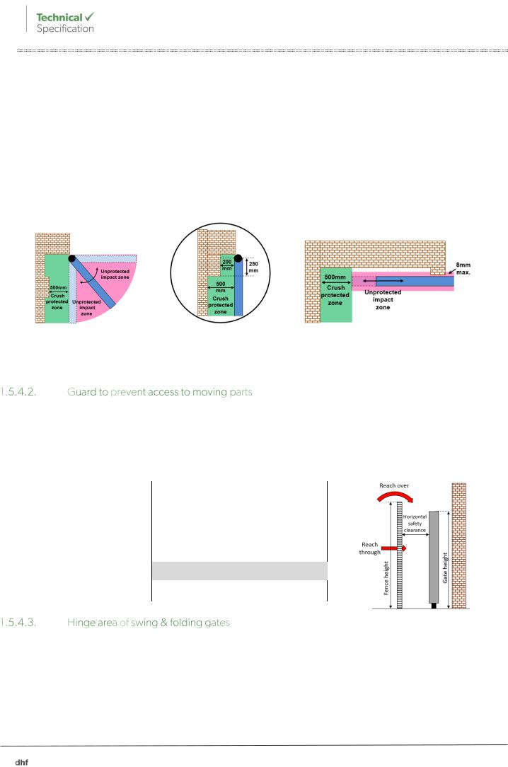
A gap greater than 500mm between a horizontally moving leaf and a fixed object eliminates the crush hazard potential at that location; this can be relaxed to 200mm within 250mm of the hinge. It should be noted however, that very few centre hung swing or folding gate hinge designs actually have 200mm of space remaining in the hinge area.
Swing gate crush zone |
Relaxation to 200mm |
Sliding gate crush zone |
|
within 250mm of the hinge |
|
Regardless of any safety distance used, an impact hazard will remain across the swept area of the leaf during opening and closing movement that should be controlled by one or more of the means described in 1.5.5 to 1.5.7.
Guards or fencing can be used to prevent access to hazardous movement and should:
(i)be permanently fixed and only removable with a tool or key
(ii)be durable and resistant to foreseeable abuse
(iii)be designed to resist climbing with vertical elements on the outside and a maximum gap of 40mm between verticals and, conform with tables 1 and 2 for reach over and reach through protection.
|
Height of |
|
|
Height of hazard |
|
||
|
|
2 |
2.2 |
2.4 |
|
||
|
guard |
|
|
||||
|
|
|
Horizontal clearance |
|
|||
|
|
|
|
|
|||
2 |
|
350 |
350 |
100 |
|
||
2.2 |
|
0 |
250 |
100 |
|
||
|
|
|
|
|
|
||
2.4 |
|
0 |
0 |
100 |
|
||
2.5 |
|
0 |
0 |
0 |
|
||
Table 1 reach over
|
Mesh size |
|
|
Horizontal clearance |
|
||||||
|
smallest |
|
|||||||||
|
|
|
Slot |
|
|
Square |
|
|
Round |
|
|
|
dimension mm |
|
|
|
|
|
|
|
|||
4-6 |
|
20 |
|
10 |
|
10 |
|
||||
6-8 |
|
40 |
|
30 |
|
20 |
|
||||
8-10 |
|
80 |
|
60 |
|
60 |
|
||||
10-12 |
|
100 |
|
80 |
|
80 |
|
||||
12-20 |
|
|
1900 |
|
120 |
|
120 |
|
|||
1Where the length of the slot is less than 40mm the safety clearance can be reduced to 120mm
20-30 |
900 |
550 |
120 |
30-100 |
900 |
900 |
900 |
Table 2 reach through
Reducing gaps at the hinge area can generate a very high force. Access to a reducing gap at a hinge area is possible from a variety of directions (see below). Reducing gaps at the hinge area should be avoided by safe design wherever possible.
13 1116:V4:04/19
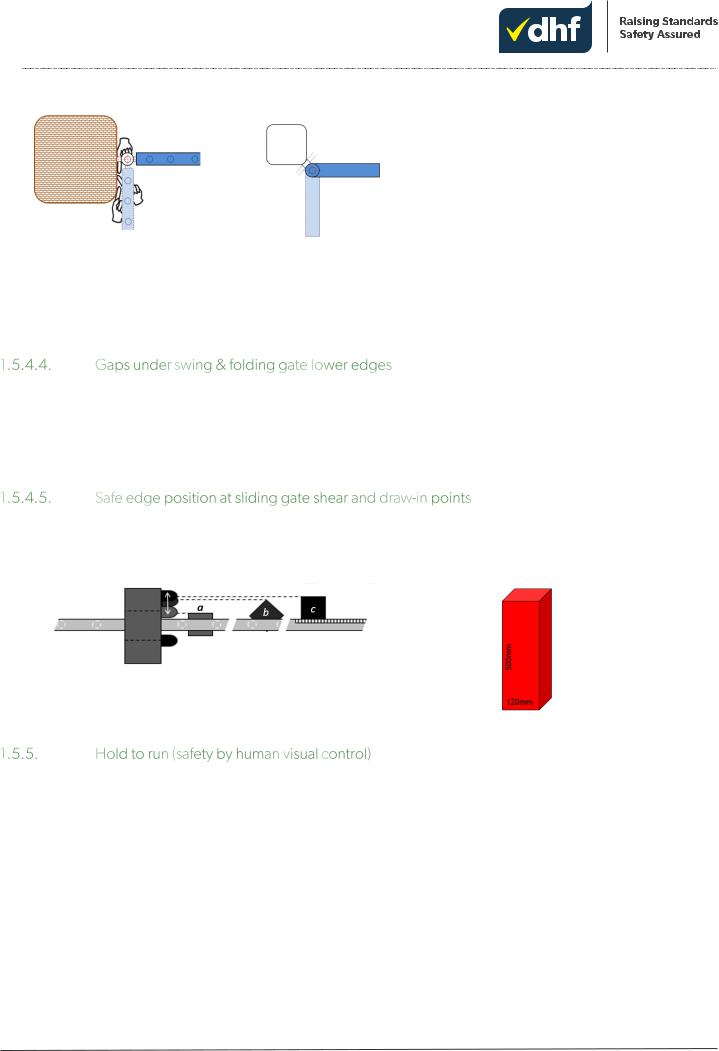
Safe design hinge area criteria:
(i) |
a constant gap of less than 4mm or |
|
more than 25mm, or |
(ii) |
a maximum gap reduction of 20% is |
|
permissible, where the overall |
|
maximum gap is less than 100mm. |
Examples of access to reducing gaps Example safe design hinge area |
Safe design hinge area criteria |
When the safe design hinge area criteria is not met, one or more of the following measures should be applied such that the hazard is controlled: hold to run; safe edge; flexible guard and in some cases fine mesh to prevent access through the infill.
Flexible guards should be durable, cover the entire hazard and not fold into the reducing gap. They will also need to be removable by key or tool for inspection and maintenance of hinges with the guarded space.
A foot crush hazard exists wherever the gap under a swing or folding gate exceeds 8mm and is less than 120mm. A crush hazard also exists wherever the gate moves over sloping or otherwise uneven ground (e.g. over kerbs). These should be controlled by one of: hold to run 1.5.5, force limitation 1.5.6 or non-contact presence detection 1.5.7.
Where the gap below the gate is less than 8mm or greater than 120mm and the swept area is level, there is no foot crush hazard present, but an impact hazard remains that should still be controlled by one of: hold to run, force limitation or non-contact presence detection; higher force is permissible where there is no crush hazard, see 1.5.6.
The safe edge should be positioned as close as possible to the moving leaf to prevent draw-in occurring.
The minimum distance allowable between the moving leaf and safe edge should be verified with a rigid rectangular test piece measuring 120mm x 120mm x 500mm. The test piece should be placed as deep as possible into the leaf infill material; the safe edge should be in close enough proximity to be activated by the test piece.
a) = Infill gaps >120mm b) = infill gaps <120mm c) = fine mesh or solid infill
The nature of the gaps in the leaf infill dictate safe positioning of the safe edges.
Warning, the test must be conducted in manual mode, not under power!
The gate or barrier should only move when pressure is being applied to the activation device and:
(i)the gate should not over travel more than 100mm on release of the activation device
(ii)sliding gates and vertically moving barriers should not over travel more than 50mm on release of the activation device in the last 500mm of horizontal movement
(iii)only trained people should use the system; the activation device should prevent unauthorised use where untrained people might be present (by use of key switch or similar)
(iv)it should only be possible to operate the activation device in such a position that allows full, direct and permanent real-time view of the leaf during the leaf movement and ensures that the person controlling the gate or barrier is not in a hazardous position (video cameras do not give a full, direct and permanent real-time view)
(v)the activation device should be the only active activation device
(vi)the gate or barrier should travel at no more than 0.5m/sec (for converging leaves this means 0.25m/sec. each). Hold to run can be used to control any reachable and visible crush, impact, shear or draw-in hazard.
Technical Specification TS 011:2019 14
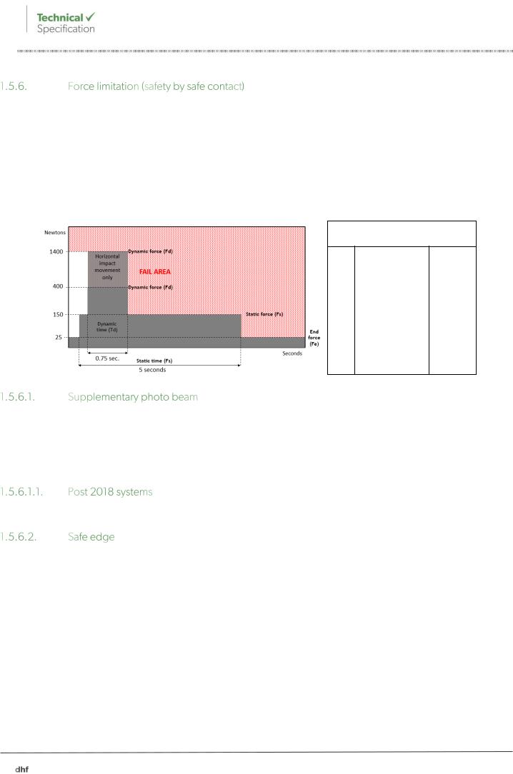
The maximum allowable forces and durations are as follows:
(i)400N at crush, shear and draw-in hazards; all vertically reducing gaps below 2.5m and horizontally reducing gaps of 500mm or less
(ii)1400N at horizontal impact hazards; contact with a horizontally moving leaf outside of a crush, shear or drawin zone
(iii)the maximum time force can remain above 150N in all cases is 0.75 seconds
(iv)the maximum time force can remain above 25N in all cases is 5 seconds
(v)the maximum time a force can exist at or below 25N in all cases is infinite.
On a force tester
Fd |
1400N |
Max |
|
|
|
Fd |
400N |
Max |
|
|
|
Td |
0.75s |
Max |
|
|
|
Fs |
150N |
Max |
|
|
|
Fe |
25N |
Max |
|
|
|
Force limitation maximum values
Force limitation should be supplemented with at least one horizontal photo beam wherever automatic closing is in use and wherever untrained persons might encounter the system. The beam(s) should be mounted between 700mm and 300mm above the ground and no more than 200mm horizontally from the face of the leaf. For swing and folding gates, the inner beam should be no more than 200mm horizontally from the open extremity of the swept area.
Traffic barriers may either use a single beam directly under the arm centre line or two beams, one to either side of the arm centre line. DHF recommends inner and outer beams, particularly on sliding gates.
Systems produced after 2018 (post publication of EN 12453:2017) with a distance greater than 150mm between the device and the opposite face of sliding and vertically moving leaves, will be required to have a beam on both sides.
Force limitation can be provided by safe edge in resistive, optical, mechanical or pneumatic format:
(i)the device must be supported by the manufacturer’s Machinery Directive Declaration of Conformity
(ii)the safe edge and any associated control device should conform to EN 12978
(iii)the safe edge should provide force limitation and reduction in accordance with clause 1.5.6
(iv)the safe edge should protect the full height/width of the crush/impact zone with the exception that the edge does not need to be sensitive in the final 30mm of each end
(v)the control circuit should meet the requirements of clause 1.5.3.11/12.
The required safe edge specification is based on: the speed & weight of the gate or barrier, the reversal torque of the operator and the time the gate or arm takes to reverse. All of these affect the amount of overtravel required in the safe edge profile.
A safe edge can be used to control any crush, impact, shear or draw-in hazard.
15 1116:V4:04/19
 Loading...