

Page 1
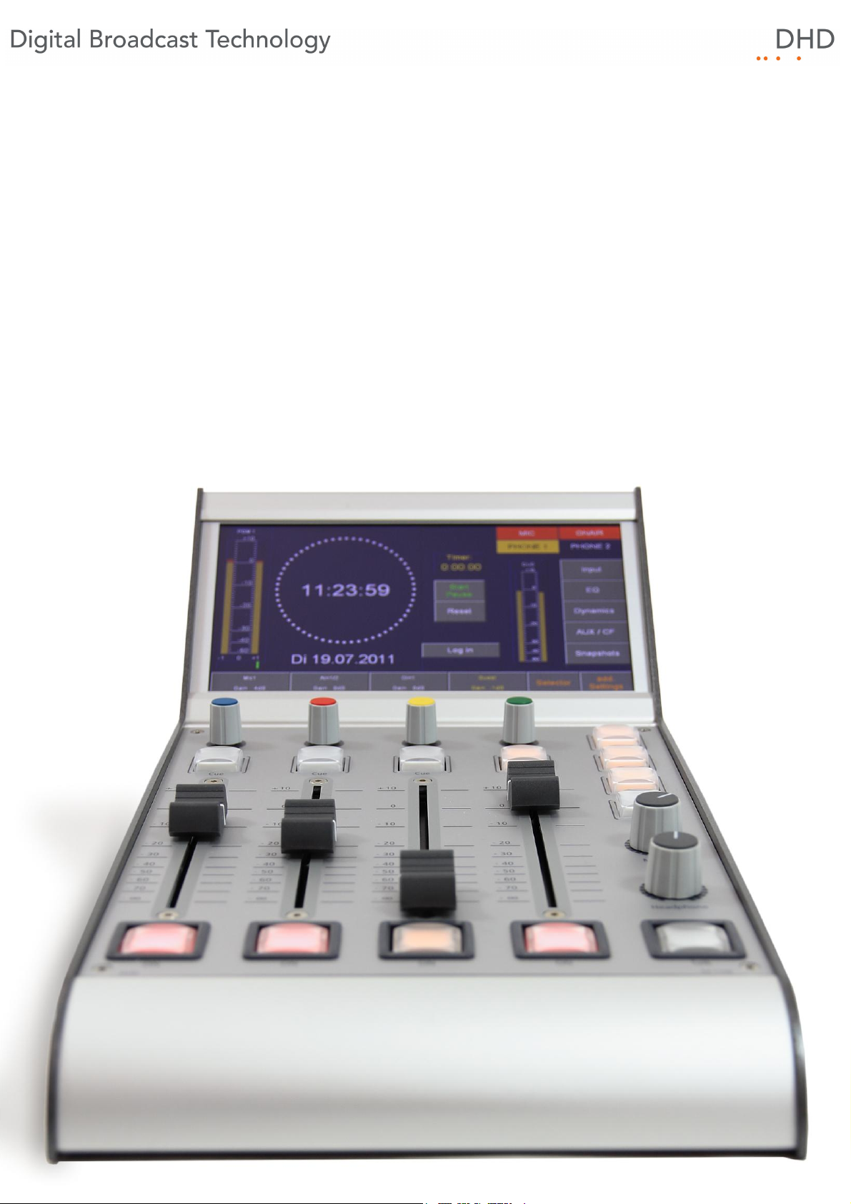
Series 52
52/DX Compact Mixing Console
Manual
© 2013 DHD Deubner Hoffmann Digital GmbH
Version: 1.2.0
Page 2
Table of Contents
Table of Contents
1 Terms of Use - Legal Disclaimer
About this Book
2
3 What is new in this version of the manual?
4 General Information
5 Key Features
Components
6
XS Core - DSP unit
1
I/O modules and connections
2
Control modules
3
................................................................................................................................... 8
................................................................................................................................... 9
......................................................................................................................................................... 9XS Multi-I/O Box
......................................................................................................................................................... 10XC Mic/Headphone/GPIO module
......................................................................................................................................................... 11XC Digital I/O/GPIO module
......................................................................................................................................................... 11XC Analog I/O/GPIO module
......................................................................................................................................................... 12DeviceLink
................................................................................................................................... 12
......................................................................................................................................................... 1652/DX control module
7 Cabling
1
2
4
5
7
8
17
1 Pin assignment of 52-1330
D-Sub Pin assignment of 52-7111
2
3 D-Sub Pin assignment of 52-7222 / 52-7223
D-Sub Pin assignment of 52-7230
4
5 Network connection
................................................................................................................................... 17
................................................................................................................................... 17
................................................................................................................................... 18
................................................................................................................................... 18
................................................................................................................................... 18
8 Connecting modules to the XS Core
9 Usage of USB audio on 52-1330
1 Option 1 - Each USB connected to a seperate PC
Option 2 - Both USB connected to single PC
2
3 Internal sample rate converter
................................................................................................................................... 21
................................................................................................................................... 21
................................................................................................................................... 22
10 Configuration
Program Menus
1
................................................................................................................................... 24
......................................................................................................................................................... 24File Menu
New Device
Open Device
Save Device
.................................................................................................................................................. 24
.................................................................................................................................................. 24
.................................................................................................................................................. 24
20
21
23
© 2013 DHD Deubner Hoffmann Digital GmbH
Page 3
Series 52 - 52/DX Compact Mixing Console Manual
Hardware
2
System Settings
3
I/O Settings
4
Console
5
Monitoring
6
Buses
7
On-Air Switch
8
Users
9
Authorisation
10
Save Device as
History
Exit
Maintenance Window
Key Functions
Logic Sources
Audio Sources
Watches - Logic Monitor
Load to Device
Load from Device
Configuration
About
.................................................................................................................................................. 24
.................................................................................................................................................. 25
.................................................................................................................................................. 25
......................................................................................................................................................... 26View Menu
.................................................................................................................................................. 26
.................................................................................................................................................. 26
.................................................................................................................................................. 26
.................................................................................................................................................. 27
.................................................................................................................................................. 28
......................................................................................................................................................... 29Transfer Menu
.................................................................................................................................................. 31
.................................................................................................................................................. 32
......................................................................................................................................................... 32Options Menu
.................................................................................................................................................. 32
......................................................................................................................................................... 33Help Menu
.................................................................................................................................................. 33
................................................................................................................................... 34
................................................................................................................................... 35
................................................................................................................................... 37
................................................................................................................................... 41
................................................................................................................................... 44
......................................................................................................................................................... 46Talkback
................................................................................................................................... 46
................................................................................................................................... 48
................................................................................................................................... 50
................................................................................................................................... 51
Index
© 2013 DHD Deubner Hoffmann Digital GmbH
Page 4
1 Terms of Use - Legal Disclaimer
Series 52
52/DX Compact Mixing Console Manual
© 2013 DHD Deubner Hoffmann Digital GmbH
This manual is copyright of DHD. It might be distributed and copied as long as it is copied completely as a whole and this
copyright notice is included.
No part of this document may be copied or distributed without prior written permission of DHD Deubner Hoffmann Digital
GmbH.
Windows is a registered trademark of Microsoft Corp., Redmond, Wash., USA. All other trademarks are the property of
their respective owners.
Specifications and design are subject to change without notice.
The content of this document is for information only. The information presented in this document does not
form part of any quotation or contract, is believed to be accurate and reliable and may be changed without
notice. No liability will be accepted by the publisher for any consequence of its use. Publication thereof
does neither convey nor imply any license under patent rights or other industrial or intellectual property
rights.
Terms of Use - Legal Disclaimer
1
Version 1.2.0, 04.02.2013
Version 1.2.0 - 04.02.2013
Specifications and design are subject to change without notice. The content of this document is for information only. The information presented in this document does not form part
of any quotation or contract, is believed to be accurate and reliable and may be changed without notice. No liability will be accepted by the publisher for any consequence of its use.
Publication thereof does neither convey nor imply any license under patent rights or other industrial or intellectual property rights.
Page 5
2
Series 52 - 52/DX Compact Mixing Console Manual
2 About this Book
This book will provide you an overview about the applications of the 52/DX Compact Mixing Console.
The content of this manual is subject to change without notice. DHD recommends to visit the DHD website once in a while
to check if there is a newer version of this document available.
How to Use this Book
The Navigation Tree
You can find the navigation tree on the left-hand-side of the PDF document. Via the entries of this tree you can directly
reach the several chapters and sections of this document. Click onto the text or the symbol of an entry to display its
content.
If a chapter includes further sections, you will find a plus-symbol in front of the entry in the navigation tree. Either you can
click onto this plus-sign or you double click the text or the symbol of the entry to make the sub-branches of the further
sections visible.
Search
You can find an alphabetical ordered list of keywords at the end of the document. Please see the page numbers in this
index to find the respective keywords in the document.
Moreover, you can use the search function of your PDF reader to seek for any words.
Links
Links are underlined to separate them from the rest of the text. These links can be a connection to other chapters or
sections in the same document or to an URL (internet address).
· Same document: The hand symbol appears if you move the mouse over the link.
· URL: The hand symbol with an additional w appears if you move the mouse over the link.
Please notice, that you need an active internet connection to be able to execute a link to an URL.
© 2013 DHD Deubner Hoffmann Digital GmbH
Specifications and design are subject to change without notice. The content of this document is for information only. The information presented in this document does not form part
of any quotation or contract, is believed to be accurate and reliable and may be changed without notice. No liability will be accepted by the publisher for any consequence of its use.
Publication thereof does neither convey nor imply any license under patent rights or other industrial or intellectual property rights.
Page 6
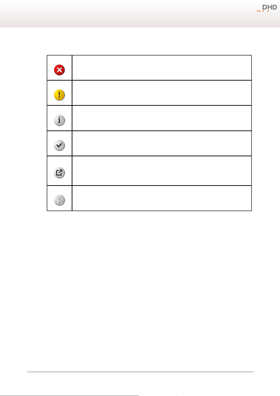
The Meaning of Advices in the Text
Warning
The demands and advices in this fields should be followed unconditional, because otherwise hardware
and software products, data bases, as well as persons may suffer a loss.
Important
The demands and advices in this fields should be followed, because these contents are necessary for the
proper operation of the DHD systems.
Note
Recommendations and further information are marked as notes. Sometimes you will also find off-topic
content in this field, which is related to the actual topic.
Tip
Tips are helpful advices, which should make work with DHD systems easier.
Weblink
In this fields you can find links to websites, which include for example an other manual or the possibility to
download a driver for the respective DHD system.
Please notice, that you need an active internet connection to be able to execute a link to an URL.
Download
You can directly open and download a file if the respective link is marked as download link (file link).
About this Book
3
Specifications and design are subject to change without notice. The content of this document is for information only. The information presented in this document does not form part
of any quotation or contract, is believed to be accurate and reliable and may be changed without notice. No liability will be accepted by the publisher for any consequence of its use.
Publication thereof does neither convey nor imply any license under patent rights or other industrial or intellectual property rights.
Version 1.2.0 - 04.02.2013
Page 7
4
Chapter / Section
State
Note
General
changed
removed wrong search results in
online manual
Chapter / Section
State
Note
Configuration - I/O Settings
changed
Information changed:
· Headroom --> Level Adjust
Configuration - Console
changed
Information changed:
· TFT view names changed Stpw
--> Tmr
· standardisation of use of keys
and buttons
Components - Control modules Central module
changed
Information changed:
· standardisation of use of keys
and buttons
Chapter / Section
State
Note
All sections.
added
Information added.
Series 52 - 52/DX Compact Mixing Console Manual
3 What is new in this version of the manual?
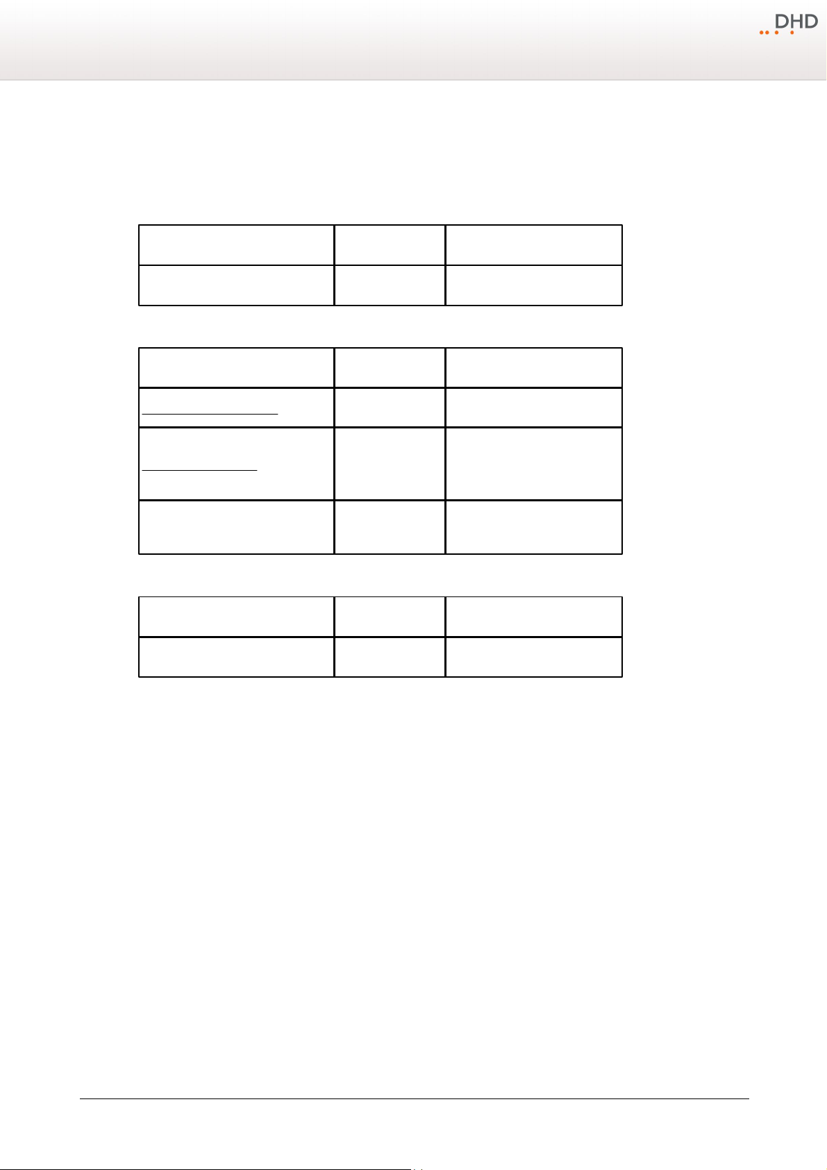
All sections that had been added, deleted or changed are listed below. Click on the entries to reach the respective sections
directly.
Current version (1.2.0) (related to DXConfig, version 7.1.13):
Version 1.1.0
Initial version (1.0.0) (related to DXConfig, version 7.1.4):
© 2013 DHD Deubner Hoffmann Digital GmbH
Specifications and design are subject to change without notice. The content of this document is for information only. The information presented in this document does not form part
of any quotation or contract, is believed to be accurate and reliable and may be changed without notice. No liability will be accepted by the publisher for any consequence of its use.
Publication thereof does neither convey nor imply any license under patent rights or other industrial or intellectual property rights.
Page 8
4 General Information
Important
Make sure that the ventilation openings of the device are not covered and that
the environmental temperature is ok to assure sufficient heat flow. (See
Installation Guide)
Important
Do not place drinking vessels or any other vessels with liquids on the device or
close to it.
Important
Changes according to hardware configuration may only be done by qualified
personnel (e.g., exchanging modules).
Safety Instructions
Ignoring the following safety instructions may lead to accidents with severe, life-threatening injuries,
caused by fire or electric shocks.
Always act according to the directions of this manual.
Fix the device well in a rack or studio furniture with the mounting orientation given by DHD.
Only connect the power cable of the device to a socket, which carries the voltage stated on the specification plate.
General Information
5
Do not place heavy objects on the device.
The device or parts of the device can get very warm during the usage. Please be careful when touching the device after a
longer operating time.
Specifications and design are subject to change without notice. The content of this document is for information only. The information presented in this document does not form part
of any quotation or contract, is believed to be accurate and reliable and may be changed without notice. No liability will be accepted by the publisher for any consequence of its use.
Publication thereof does neither convey nor imply any license under patent rights or other industrial or intellectual property rights.
Version 1.2.0 - 04.02.2013
Page 9
6
Important
The cleaning of a device should be done in Off-Air mode as possible. That means
the device does not handle relevant audio and/or logic signals that are
integrated in the current broadcasting process.
Important
If a damp cloth is used for cleaning, you have to switch off the DHD device and
to disconnect all hot cables from it.
Warning
Never use a dripping wet cloth. In no case water and/or cleaner may enter the
device, since this could lead to electric shocks and fires!
Warning
Never use solvent or thinner for cleaning the surfaces. Furthermore, do not
use abrasive as well as sharp objects for cleaning. You will damage the surface
of the device.
Series 52 - 52/DX Compact Mixing Console Manual
Care Instructions
To clean your DHD device, in general a soft, lint-free and dry cloth is sufficient. In case of severe soiling, you can use a
damp cloth and household detergent.
© 2013 DHD Deubner Hoffmann Digital GmbH
Specifications and design are subject to change without notice. The content of this document is for information only. The information presented in this document does not form part
of any quotation or contract, is believed to be accurate and reliable and may be changed without notice. No liability will be accepted by the publisher for any consequence of its use.
Publication thereof does neither convey nor imply any license under patent rights or other industrial or intellectual property rights.
Page 10
5 Key Features
Download
You can download a PDF-file with the functional range of all Series 52 Core
devices directly from the following link:
xc_xd_xs_core_functional_range.pdf
The Series 52 Mixing Console 52/DX has been designed to be an easy-to-use tool for a broad range of TV and radio
broadcasting applications. With its 4 faders and its compact table top design, it is ideal for OnAir, in the OB van, for News,
Edit- and Ingest Stations.
The 52/DX uses a special real-time operation system running in the 52/XS Core. There is no PC-based system inside and
it works completely without any PC.
The configuration software runs on standard Windows(TM) based PCs. However, this PC is not required to run the 52/DX
from day to day – it is only needed for setting it up.
A Series 52 Mixing Console 52/DX remotely controls the processing power of a 52/XS core via TCP/IP. The combination of
the proved and reliable DSP power of an 52/XS Core provides you with a great variety of features.
The configuration of the console is realised via a simplified version of the well-proven DHD Toolbox5, called DXConfig. The
52/DX allows to make use of the established DHD-PC software products: DSP-Control-Software, Remote-Control-Software,
Snapshot-Manager, Snapshot-Server. A XS Core extended feature upgrade licence provides Toolbox5 configuration
capability like other Series 52 products.
Key Features
7
Specifications and design are subject to change without notice. The content of this document is for information only. The information presented in this document does not form part
of any quotation or contract, is believed to be accurate and reliable and may be changed without notice. No liability will be accepted by the publisher for any consequence of its use.
Publication thereof does neither convey nor imply any license under patent rights or other industrial or intellectual property rights.
Version 1.2.0 - 04.02.2013
Page 11
8
Series 52 - 52/DX Compact Mixing Console Manual
6 Components
The audio and logic system of the 52/DX Compact Mixing Console consists of the 52/XS Core (DSP unit), the I/O boxes
(the input/output modules) and control modules.
In the following sections, these main components of a 52/DX mixing console are presented in detail.
6.1 XS Core - DSP unit
The powerful 52/XS Core is an independent DSP system which does not require a PC for operation. There are no fans,
hard discs or batteries inside the 52/XS Core and in the I/O boxes, allowing silent and low-maintenance operation directly
in the studio.
High-performance 40-bit floating-point digital signal processing for:
· 3-band fully parametric equalizers, subsonic filter, dynamics, limiter, delay for all 16 fader channels, mono or stereo
· 32 summing busses (mono), Aux busses, clean feeds and PFL
· 6 clean feeds (mix-minus, mono or stereo)
· 4 monitoring busses for control room and studio support
· flexible talkback, logic and GPIO system
· integrated routing matrix
· internal tone generator
· Gigabit audio network for 512 input and 512 output channels for low-latency interconnection between 52/XS cores or to
other DHD products
· internal or external 48 kHz or 44.1 kHz sync
Other features of the XS Core:
· highly efficient external wide-range power supply, Energy Star Level V, redundancy option
· minimal system power consumption
· expandable modular system allows optional integration of other DHD product lines
· serial or TCP/IP interface options to radio automation or other external control systems
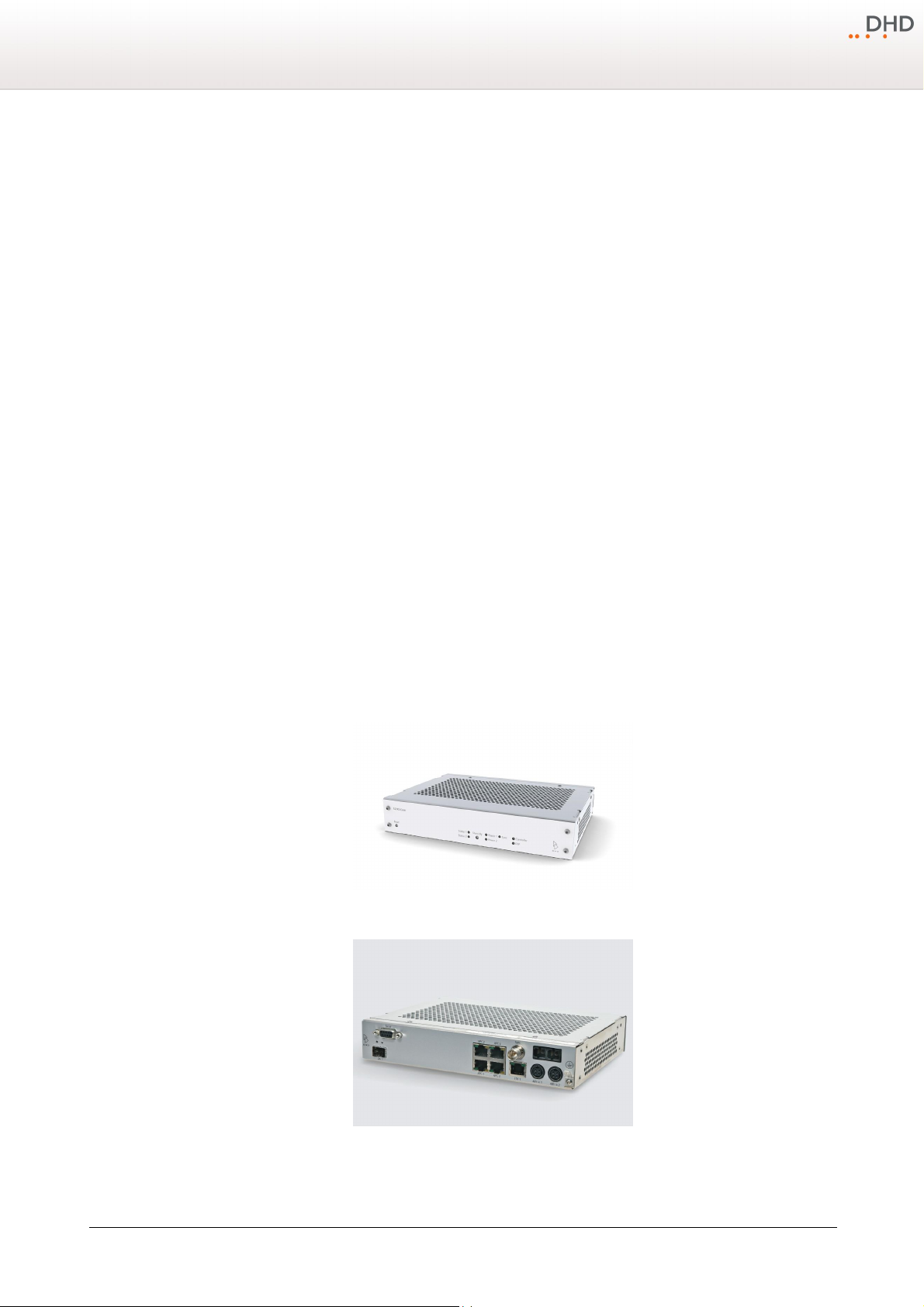
Front view 52-1804
Rear View 52-1804
© 2013 DHD Deubner Hoffmann Digital GmbH
Specifications and design are subject to change without notice. The content of this document is for information only. The information presented in this document does not form part
of any quotation or contract, is believed to be accurate and reliable and may be changed without notice. No liability will be accepted by the publisher for any consequence of its use.
Publication thereof does neither convey nor imply any license under patent rights or other industrial or intellectual property rights.
Page 12
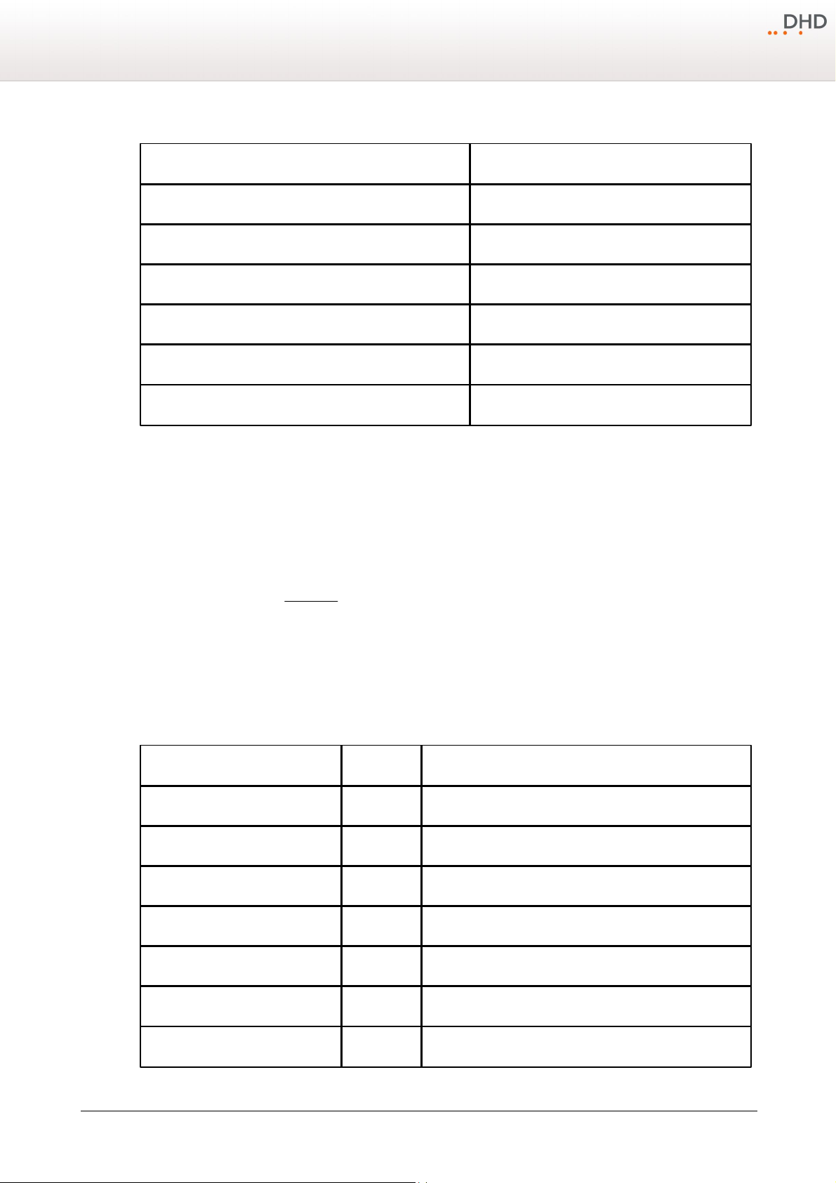
In the following table the main Features of the 52-1804 with a 52/DX control module are listed.
Feature
52-1804
support for redundant power supply
yes
number of supported faders
4
number of supported I/O boxes
3
number of audio, power & control ports (APC)
4
serial interface for external control
yes
TCP/IP interface for external control
yes
Interface type
Number
Specifications
Microphone/line inputs
2
-77…+18 dBu sensitivity
Headphone outputs
2
stereo
Analog line inputs
8
max. +24 dBu
Analog line outputs
8
max. +24 dBu
Digital inputs, AES3/EBU
3
sample rate converter, stereo
Digital inputs, S/PDIF
1
sample rate converter, stereo
Digital inputs, USB
2
sample rate converter, stereo
Components
9
6.2 I/O modules and connections
Different I/O modules for audio and control inputs and outputs can be used for the 52/DX. Please find more information
about the I/O modules on the following pages.
It is also possible to connect two XS cores directly via Ethernet cable to exchange audio signals. Please find more
information about this in the DeviceLink section.
6.2.1 XS Multi-I/O Box
The 52-1330 XS Multi-I/O Box is an input/output module with common audio interfaces for the 52/DX mixing console.
In the following table you can find the type and number of interfaces, which are available on each XS Multi-I/O Box 521330:
Specifications and design are subject to change without notice. The content of this document is for information only. The information presented in this document does not form part
of any quotation or contract, is believed to be accurate and reliable and may be changed without notice. No liability will be accepted by the publisher for any consequence of its use.
Publication thereof does neither convey nor imply any license under patent rights or other industrial or intellectual property rights.
Version 1.2.0 - 04.02.2013
Page 13
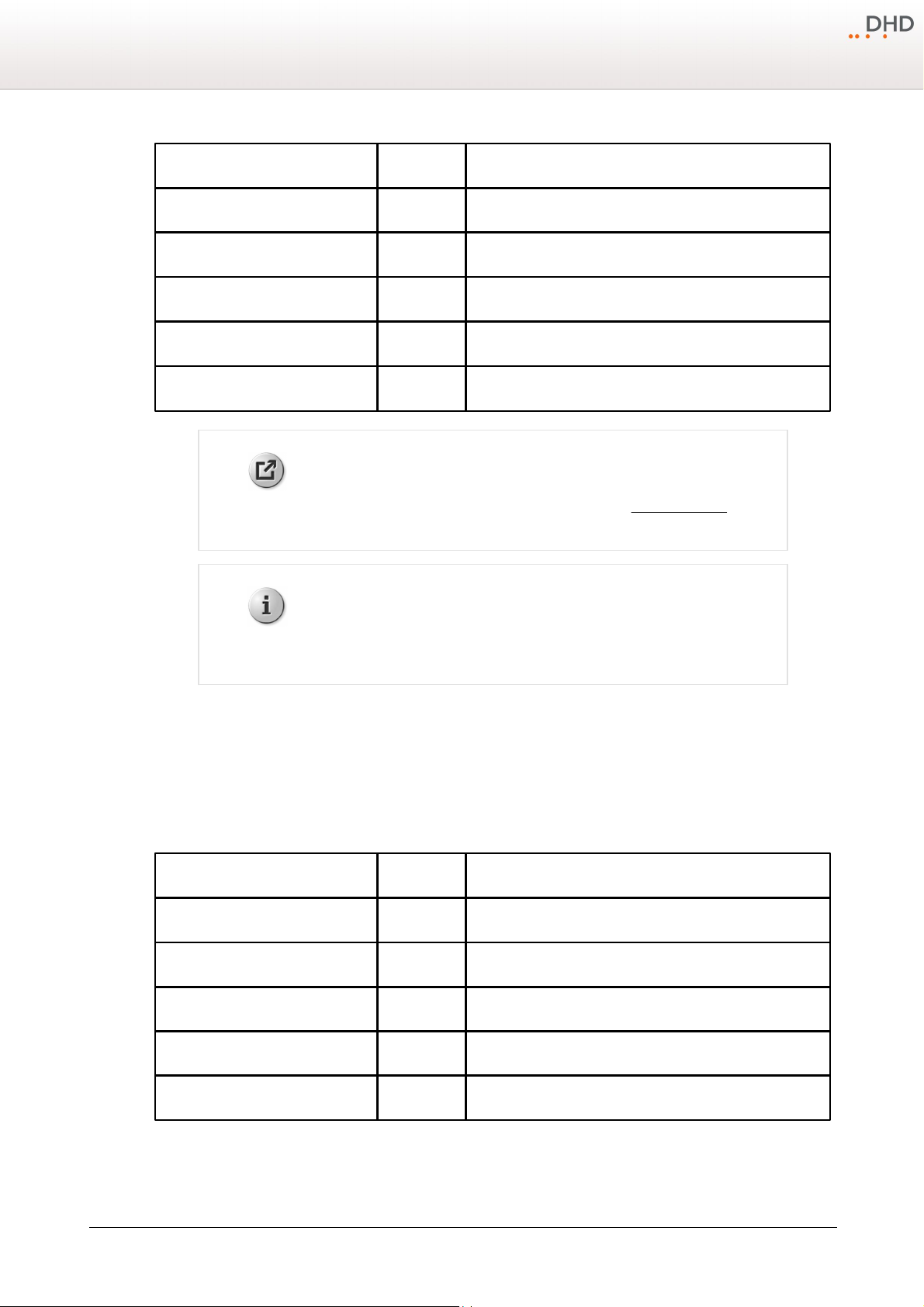
10
Digital outputs, AES3/EBU
2
sample rate converter, stereo
Digital outputs, S/PDIF
1
sample rate converter, stereo
Digital outputs, USB
2
sample rate converter, stereo
General purpose inputs
10
opto coupler
General purpose outputs
10
photo mos relays
Analog control inputs
2
for external potentiometers
Weblink
Please find a PDF file with pin assignments in the 52/DX Download area on
www.dhd-audio.com.
Note
Breakout cables for the D-sub connectors of the 52/XS Multi-I/O Box are not
available from DHD.
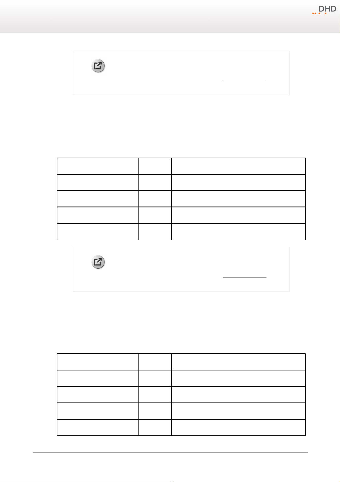
Interface type
Number
Specifications
Microphone/line inputs
4
-77…+18 dBu sensitivity
Headphone outputs
4
stereo
General purpose inputs
4
opto coupler
General purpose outputs
8
photo mos relays
Analog control inputs
4
for external potentiometers
Series 52 - 52/DX Compact Mixing Console Manual
6.2.2 XC Mic/Headphone/GPIO module
The 52-7230 XC Mic/Headphone/GPIO module is an input/output module with microphone inputs and headphone outputs
for the 52/DX mixing console.
In the following table you can find the type and number of interfaces, which are available on each XC Mic/Headphone/
GPIO module 52-7230:
© 2013 DHD Deubner Hoffmann Digital GmbH
Specifications and design are subject to change without notice. The content of this document is for information only. The information presented in this document does not form part
of any quotation or contract, is believed to be accurate and reliable and may be changed without notice. No liability will be accepted by the publisher for any consequence of its use.
Publication thereof does neither convey nor imply any license under patent rights or other industrial or intellectual property rights.
Page 14
Weblink
Please find a PDF file with pin assignments in the 52/DX list of modules on www.
dhd-audio.com.
6.2.3 XC Digital I/O/GPIO module
Interface type
Number
Specifications
Digital inputs, AES3/EBU
4
sample rate converter, 24 bit, stereo
Digital outputs, AES3/EBU
4
sample rate converter, 24 bit, stereo
General purpose inputs
4
opto coupler
General purpose outputs
4
photo mos relays
Weblink
Please find a PDF file with pin assignments in the 52/DX list of modules on www.
dhd-audio.com.
Interface type
Number
Specifications
Line inputs
4
18 dBu max.
Line outputs
4
18 dBu max.
General purpose inputs
4
opto coupler
General purpose outputs
4
photo mos relays
The 52-7111 XC Digital I/O/GPIO module is an input/output module with AES3/EBU-S/PDIF inputs and outputs for the 52/
DX mixing console.
In the following table you can find the type and number of interfaces, which are available on each XC Digital I/O/GPIO
module 52-7111:
Components
11
6.2.4 XC Analog I/O/GPIO module
The 52-7222/52-7223 XC Analog I/O/GPIO module is an input/output module with analog line inputs and outputs for the
52/DX mixing console.
In the following table you can find the type and number of interfaces, which are available on each XC Analog I/O/GPIO
module 52-7222:
Specifications and design are subject to change without notice. The content of this document is for information only. The information presented in this document does not form part
of any quotation or contract, is believed to be accurate and reliable and may be changed without notice. No liability will be accepted by the publisher for any consequence of its use.
Publication thereof does neither convey nor imply any license under patent rights or other industrial or intellectual property rights.
Version 1.2.0 - 04.02.2013
Page 15
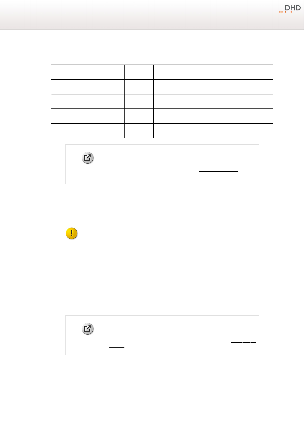
12
Interface type
Number
Specifications
Line inputs
4
24 dBu max.
Line outputs
4
24 dBu max.
General purpose inputs
4
opto coupler
General purpose outputs
4
photo mos relays
Weblink
Please find a PDF file with pin assignments in the 52/DX list of modules on www.
dhd-audio.com.
Important
To use the DeviceLink, each XS Core requires an
XC/XS Core Audio Network
licence.
Weblink
For a comprehensive list of all 52/DX modules, please see the 52/DX List of
Modules.
Series 52 - 52/DX Compact Mixing Console Manual
In the following table you can find the type and number of interfaces, which are available on each XC Analog I/O/GPIO
module 52-7223:
6.2.5 DeviceLink
To exchange audio signals directly between two XS cores, you can connect them directly by a shielded CAT5 or CAT6
cable on an APC port on each XS core.
Each DeviceLink connection can send and receive 48 audio channels at the same time. This connection does not transmit
any control signals.
6.3 Control modules
The control module is the interface between the user and the functions of the mixing system. The 52/DX control modules
has an integrated TFT Display. Due to it is sensitive to touch, you can design views with buttons to control functions via
the TFT displays.
The control module consists of control elements – such as faders, hardware keys, TFT buttons, rotary knobs – and status
indicators. These are for example LEDs inside the keys, or defined parts of TFT views. Some typical applications for
displaying information to the user are:
· LEDs showing the PFL status for a given channel.
· An alphanumeric display shown on the TFT shows, which input signal is selected for a given channel.
· LEDs inside the keys are switched on or off to indicate the state of the key.
© 2013 DHD Deubner Hoffmann Digital GmbH
Specifications and design are subject to change without notice. The content of this document is for information only. The information presented in this document does not form part
of any quotation or contract, is believed to be accurate and reliable and may be changed without notice. No liability will be accepted by the publisher for any consequence of its use.
Publication thereof does neither convey nor imply any license under patent rights or other industrial or intellectual property rights.
Page 16
Components
The control module is tightly integrated with the control engine. It collects all events from the faders, rotary knobs and
buttons and sends back the information into the status indicators and displays.
To make configuration easier, the software allows to print out labels for the keys of the control module. These labels are
slid under the key caps. If necessary, they can be changed again later to reflect changes in the configuration of the
system.
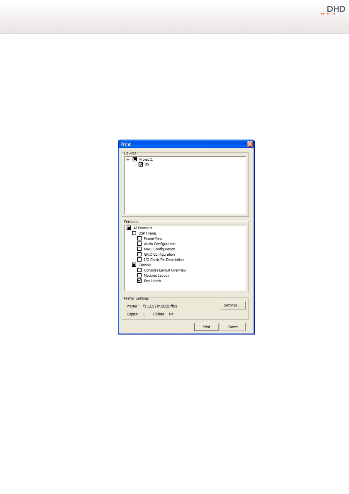
To print the key labels follow these steps:
1. In the
2. In the
3. In the
4. If required, change your printer in the
5. Click
Print
menu, select print. The
File
Devices
area, select the check box in front of the device name (e.g., SX).
Printouts
.
area, select the
Print
Key Labels
window opens (see figure Print window).
check box.
Printer Settings
area.
13
Print window
The keys on the control modules are labeled with their default functionality. You can insert printed film labels in the keys
to customise the fader modules. To insert a label into the keys, follow these steps:
Version 1.2.0 - 04.02.2013
Specifications and design are subject to change without notice. The content of this document is for information only. The information presented in this document does not form part
of any quotation or contract, is believed to be accurate and reliable and may be changed without notice. No liability will be accepted by the publisher for any consequence of its use.
Publication thereof does neither convey nor imply any license under patent rights or other industrial or intellectual property rights.
Page 17
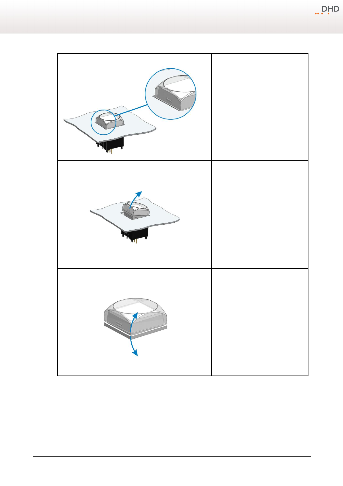
14
1.
The push-button caps can be removed to
insert a customised label. Cap and diffuser are
connected by a snap-fit on the right and on
the left of the pushbutton.
2.
Grab the cap on the upper and lower side an
pull it away from the black main part of the
push button.
3.
Separate the white coloured diffuser and the
transparent cap by pulling apart both parts.
Series 52 - 52/DX Compact Mixing Console Manual
© 2013 DHD Deubner Hoffmann Digital GmbH
Specifications and design are subject to change without notice. The content of this document is for information only. The information presented in this document does not form part
of any quotation or contract, is believed to be accurate and reliable and may be changed without notice. No liability will be accepted by the publisher for any consequence of its use.
Publication thereof does neither convey nor imply any license under patent rights or other industrial or intellectual property rights.
Page 18
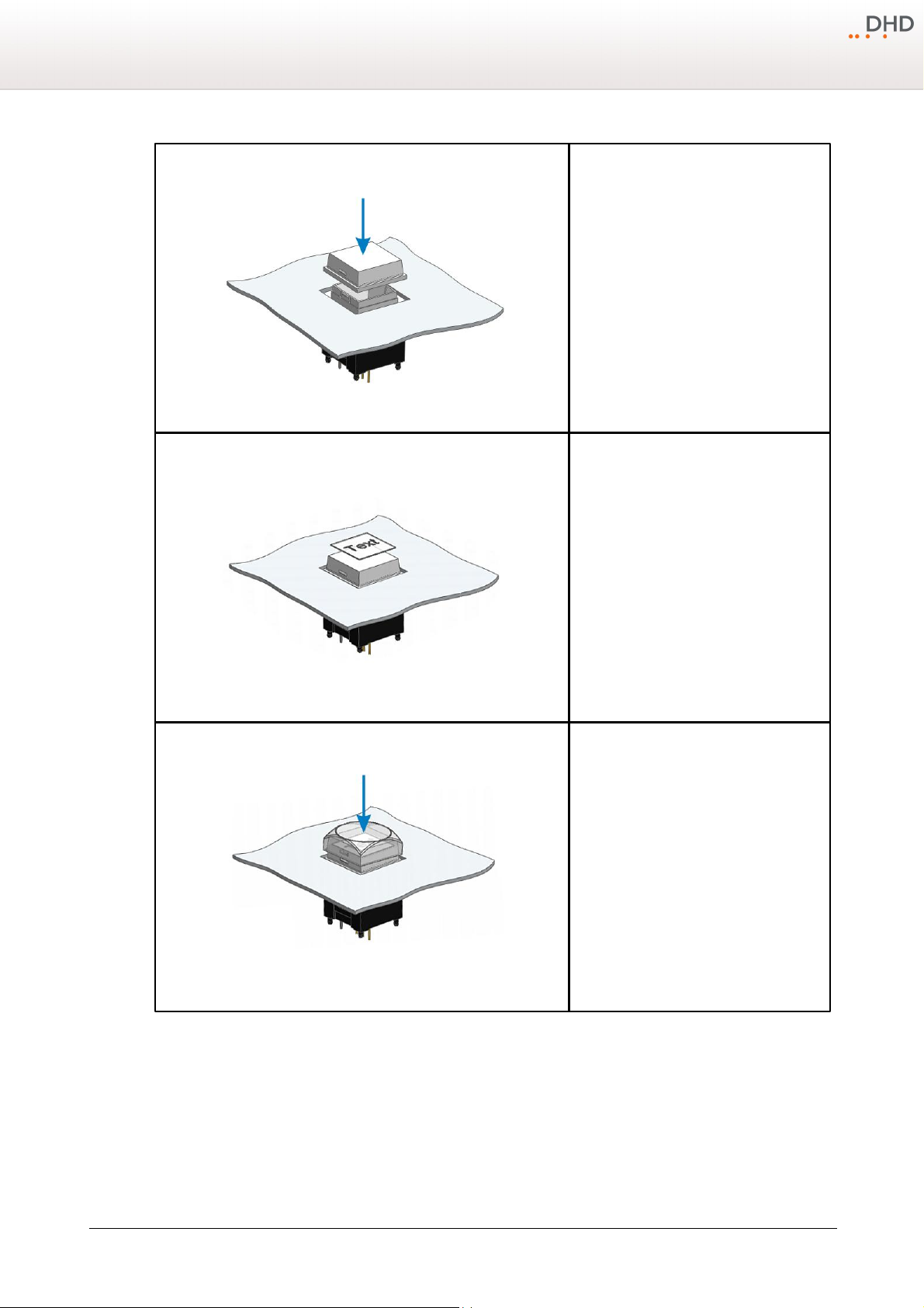
Components
4.
Put the diffuser on the main push-button part
and push it down until the snap-fits click into
their positions. Please make sure, that the
snap-fits are located on the right and left
hand side.
5.
Put a transparent film label (dimensions 12
mm x 12 mm) on the diffuser.
6.
Put the cap over the film label and the
diffuser and push it down until the snap-fits
click into their positions. Please make sure,
that the snap-fits of the cap are located on
the left and right.
15
Specifications and design are subject to change without notice. The content of this document is for information only. The information presented in this document does not form part
of any quotation or contract, is believed to be accurate and reliable and may be changed without notice. No liability will be accepted by the publisher for any consequence of its use.
Publication thereof does neither convey nor imply any license under patent rights or other industrial or intellectual property rights.
Version 1.2.0 - 04.02.2013
Page 19
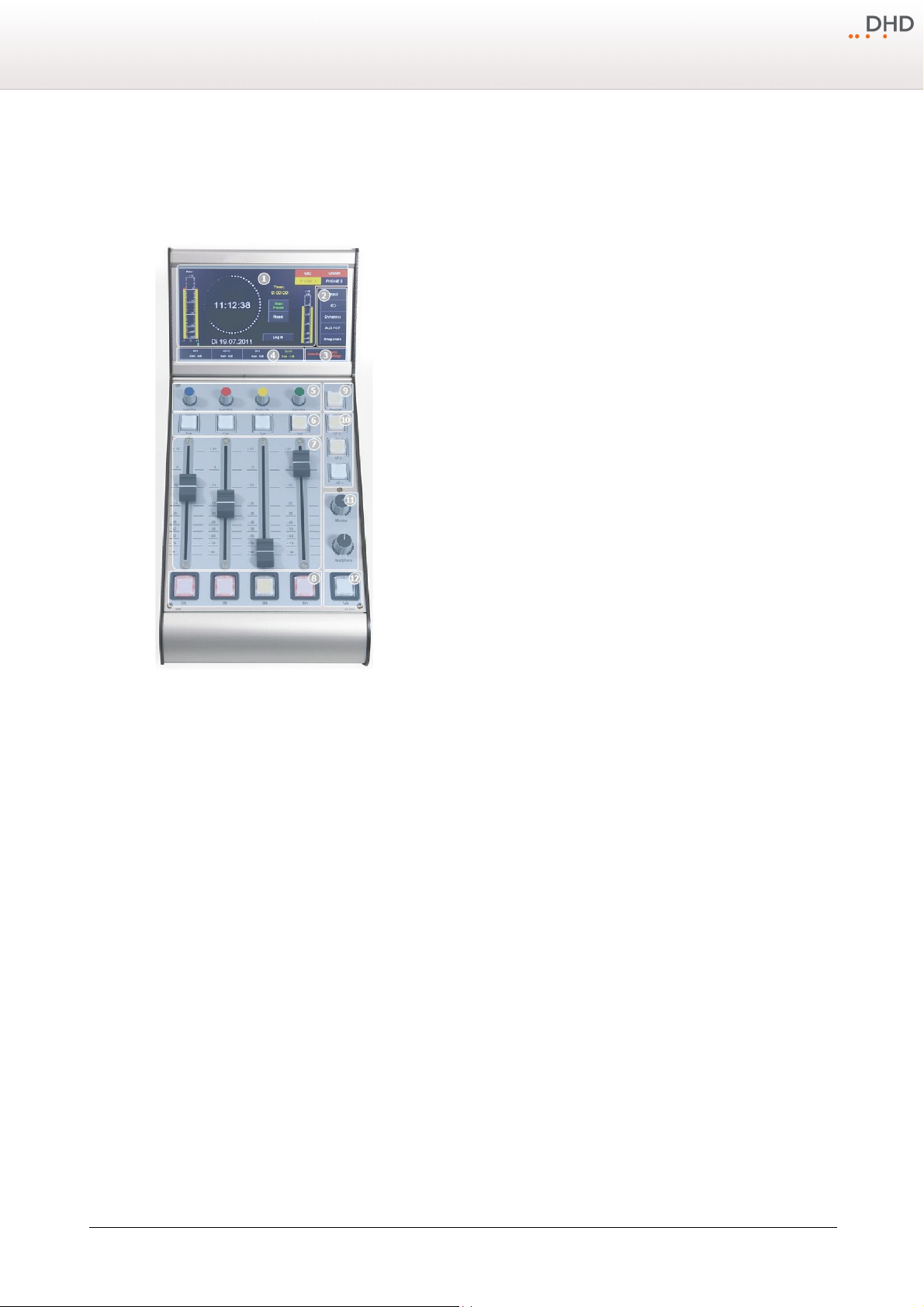
16
52-1104 top view
1
The TFT/Touch Display shows diverse pre-set TFT pages. These pages show,
for example peak meters, correlation display, clock, stopwatch and setting of
EQ, dynamics unit, snapshots and other parameters. The main page can be
changed to other preset pages in the configuration software.
This TFT display is not only able to show information. Due to it is sensitive to
touch, you can use views with buttons to control functions via the TFT screens.
2
To change parameters of a selected channel, press the
Input, EQ, Dynamic
or Aux
button to switch between the TFT pages. To save or load Snapshots
press the Snapshot button.
3
When a channel is selected, you can use these TFT buttons to navigate
between the
Input, EQ, Dynamic or Aux
TFT pages. When no channel is
selected, you have access to the
Selector
view and the
add. Settings
view.
4
Access button on TFT Touch display.
With this button you can select a channel, on which you want to make further
settings. If the button is pushed, and a TFT settings page is selected, you can
see the associated settings, for example EQ settings on the TFT display. All
changes belong to the selected fader channels. To deselect the fader channel,
push the
Select
key again or select another fader channel by pushing the
associated select key.
This Access button also provides additional information about the channel
below, these are: the channel name, the used DSP functions, an input meter
and the current gain value.
5
Encoder section for control of gain, EQs, dynamics and other settings.
The 52-1104 has four coloured encoders. These have two function modes:
· In case of no channel is selected by an access button, the encoders work as gain control for the fader channel
below. On channels with a Microphone input source, you can change the encoder function to analog gain control
(AGain) by pushing the encoder.
· When a channel is selected, by pressing an access button, the encoders work as control for parameters for EQ,
dynamics, Aux etc. on the TFT/Touch display. You can see a coloured frame around the parameters on the TFT/
Touch display, this colour shows, which encoder controls which parameter.
6
The
Cue
key is similar to a PFL key. Push this key to route the pre fader signal of a fader channel to the PFL bus.
7
Use the fader to control the audio level from -oo to 0 dB with an additional gain of +10 dB.
8
Push the
ON
key to switch the fader channel on or off. If the key lights up, the fader channel is on.
9
Program
monitor selector key, expanded by touch-display selector. When this key is pressed, the PGM bus signal will
be switched to the monitor 1 bus. The preselected audio source of monitor bus 1 will be monitored again, when the
Program
key is off. (see Configuration - Console)
10
You can use these
GP
keys (General Purpose keys) to switch GPOs and get status signalisation from a GPI, or any
other available logic source. (see Configuration - Console)
11
Professional high-grade volume potentiometers.
12
It is possible to configure this talk key for a simple talkback, for example to a sound booth or an additional mixing
console. (see Configuration - Console)
Series 52 - 52/DX Compact Mixing Console Manual
6.3.1 52/DX control module
The 52/DX control module 52-1104 is a table top module including a 7" TFT Touch Display, 4 faders, push buttons,
encoder and potentiometers.
© 2013 DHD Deubner Hoffmann Digital GmbH
Specifications and design are subject to change without notice. The content of this document is for information only. The information presented in this document does not form part
of any quotation or contract, is believed to be accurate and reliable and may be changed without notice. No liability will be accepted by the publisher for any consequence of its use.
Publication thereof does neither convey nor imply any license under patent rights or other industrial or intellectual property rights.
Page 20
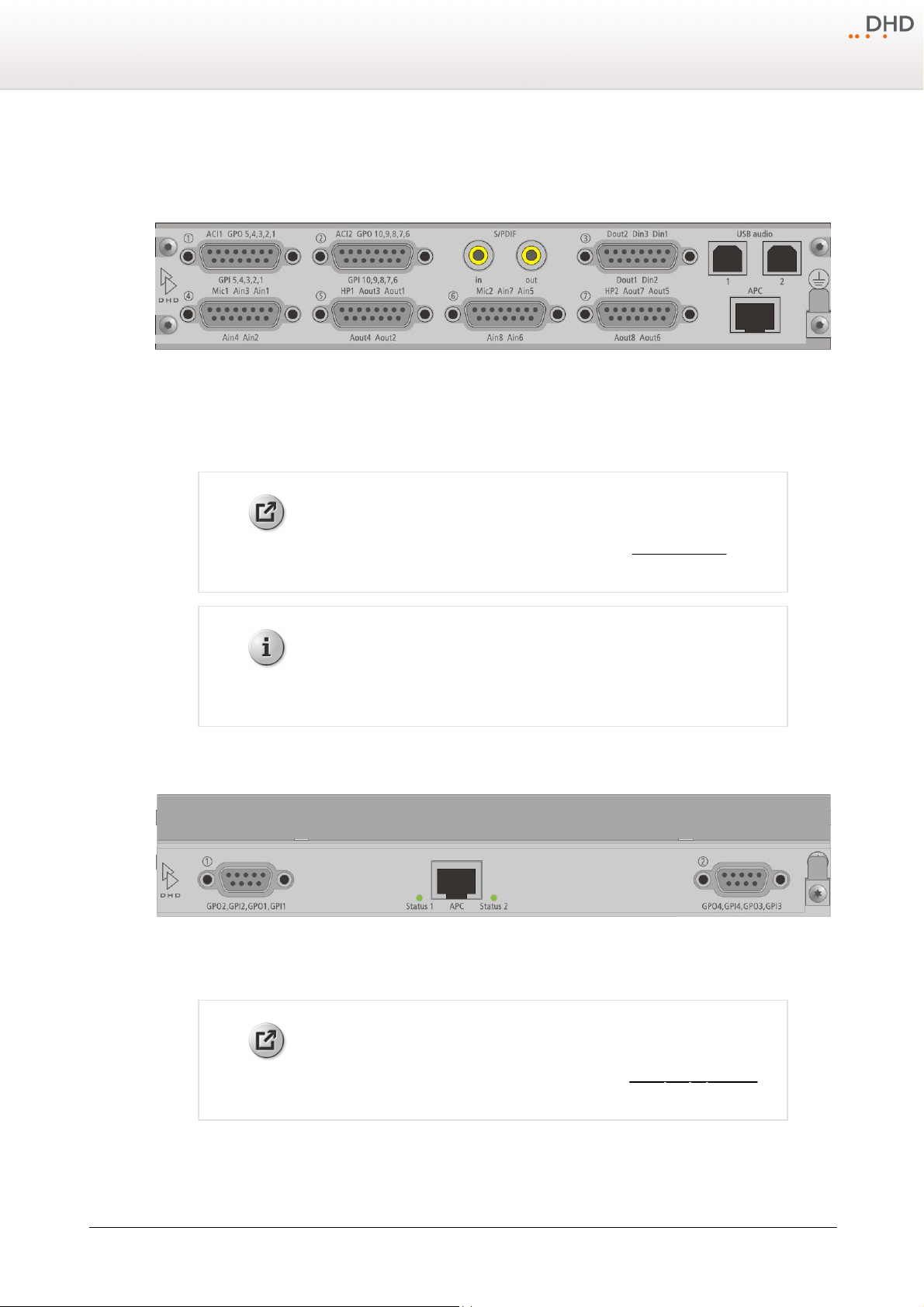
7 Cabling
Weblink
Please find a PDF file with pin assignments in the 52/SX Download area on
www.dhd-audio.com.
Note
Breakout cables for the D-sub connectors of the 52/XS Multi-I/O Box are not
available from DHD.
Weblink
Please find a PDF file with pin assignments in the 52/DX List of Modules on
www.dhd-audio.com.
7.1 Pin assignment of 52-1330
The connectors of the 52-1330 are D-sub type (15 pins), apart from the S/PDIF, USB audio and APC.
Rear View 52-1330
Cabling
17
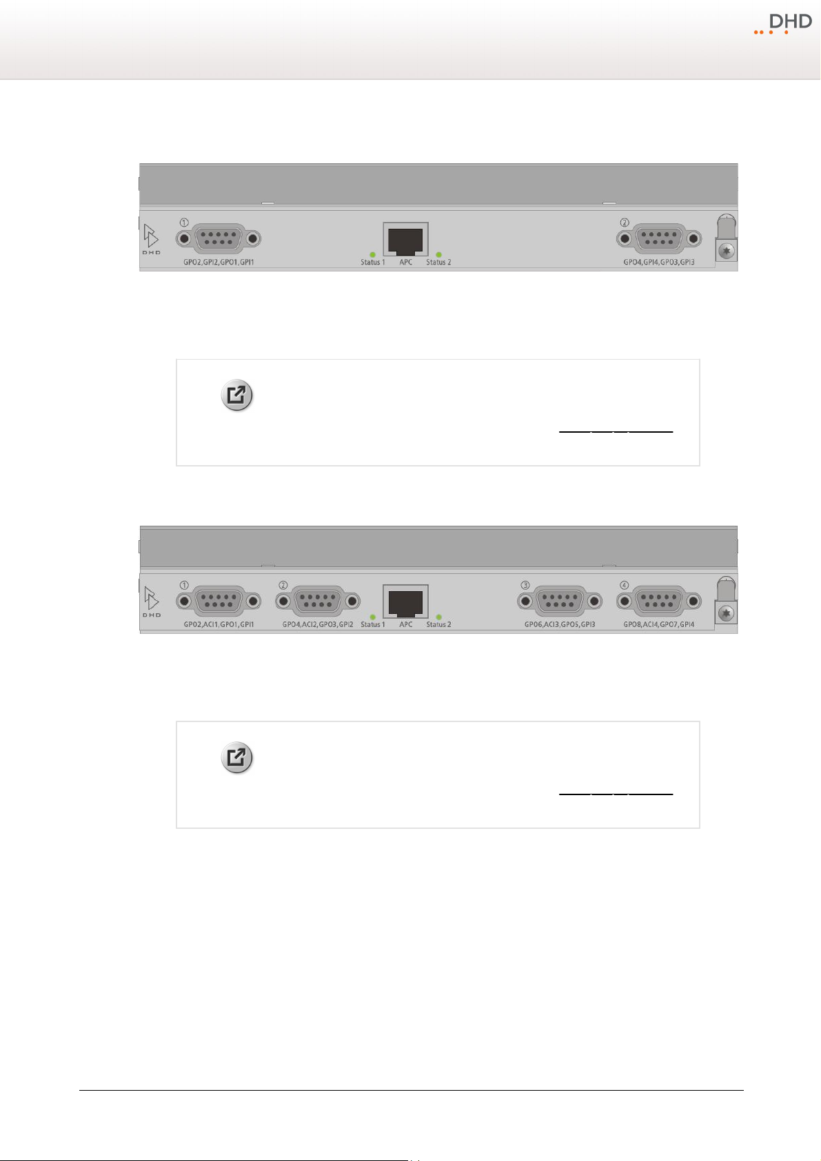
7.2 D-Sub Pin assignment of 52-7111
Rear View 52-7111
The connectors on the rear site of the 52-7111 are D-sub type (9 pins) and provide all GPIOs for this module.
Specifications and design are subject to change without notice. The content of this document is for information only. The information presented in this document does not form part
of any quotation or contract, is believed to be accurate and reliable and may be changed without notice. No liability will be accepted by the publisher for any consequence of its use.
Publication thereof does neither convey nor imply any license under patent rights or other industrial or intellectual property rights.
Version 1.2.0 - 04.02.2013
Page 21
18
Weblink
Please find a PDF file with pin assignments in the 52/DX List of Modules on
www.dhd-audio.com.
Weblink
Please find a PDF file with pin assignments in the 52/DX List of Modules on
www.dhd-audio.com.
Series 52 - 52/DX Compact Mixing Console Manual
7.3 D-Sub Pin assignment of 52-7222 / 52-7223
Rear View 52-7222 / 52-7223
The connectors on the rear site of the 52-7222 and 52-7223 are D-sub type (9 pins) and provide all GPIOs for this
module.
7.4 D-Sub Pin assignment of 52-7230
Rear View 52-7230
The connectors on the rear site of the 52-7230 are D-sub type (9 pins) and provide all GPIOs and analog control inputs
(ACI) for this module.
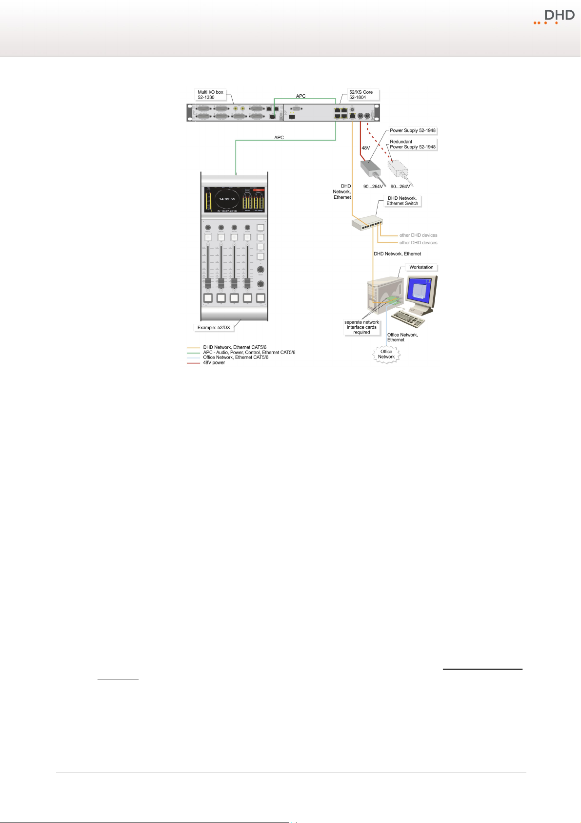
7.5 Network connection
To connect a PC for maintenance and configuration or the usage of DHD software together with a 52/SX console, please
create a DHD exclusive network.
The following drawing shows a possible 52/SX installation and it should explain the Ethernet wiring of this application.
© 2013 DHD Deubner Hoffmann Digital GmbH
Specifications and design are subject to change without notice. The content of this document is for information only. The information presented in this document does not form part
of any quotation or contract, is believed to be accurate and reliable and may be changed without notice. No liability will be accepted by the publisher for any consequence of its use.
Publication thereof does neither convey nor imply any license under patent rights or other industrial or intellectual property rights.
Page 22
Cabling
Manufacturer
Type
3com
Superstack 3, Baseline Switch
16 Port 10/100
Ref. 3C16470
3com
Superstack 3, Baseline Switch
24 Port 10/100
Ref. 3C16471
Allied Telesyn
AT-FS713FC/SC
12x RJ45
1x SC
http://www.alliedtelesyn.de
Allied Telesyn
AT-FS708
8x RJ45
http://www.alliedtelesyn.de
19
Example of a 52/DX installation.
Connect the
ETH 1
port of the 52/XS Core to the configuration PC or to the DHD Ethernet network, where the PC with
the configuration software is located. To establish the connection to the office network, you should use a server PC with a
second network interface card to avoid slowing down the communication in the DHD network and to block non-authorised
access to the connected DHD systems. Please use shielded CAT5 cables continuous for wiring. But DHD recommends to
use shielded CAT6 cables for longer distances.
Use only switches in the DHD network, which are shipped and/or recommended by DHD for the usage in this network.
Especially the switches must be unmanaged switches working with a speed of 100 Mbit/s.
The following non-PoE switches are tested by DHD and are recommended for the usage in DHD Ethernet networks:
Specifications and design are subject to change without notice. The content of this document is for information only. The information presented in this document does not form part
of any quotation or contract, is believed to be accurate and reliable and may be changed without notice. No liability will be accepted by the publisher for any consequence of its use.
Publication thereof does neither convey nor imply any license under patent rights or other industrial or intellectual property rights.
The control modules and I/O boxes have to be connected to the
the XS Core)
ports of the 52/XS Core (see Connecting modules to
APC
Version 1.2.0 - 04.02.2013
Page 23
20
Important
Use always shielded CAT5 or CAT6 ethernet cables (at least S/UTP, F/UTP or SF/UTP) to connect
these modules to the XS core.
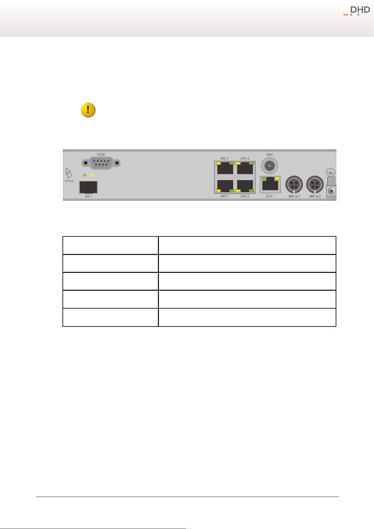
Name of the APC port
52-1804
APC 1
52-1104 52/DX control module
APC 2
I/O box 3 / DeviceLink 3
APC 3
I/O box 2 / DeviceLink 2
APC 4
I/O box 1 / DeviceLink 1
Series 52 - 52/DX Compact Mixing Console Manual
8 Connecting modules to the XS Core
The control module and I/O boxes have to be connected to the APC ports of the 52/XS Core 52-1804. It is important to
connect the peripheral modules to the correct APC port.
Rear view of 52-1804
In the following table you can find the assignment of the control module, I/O boxes and DeviceLinks to the APC ports.
© 2013 DHD Deubner Hoffmann Digital GmbH
Specifications and design are subject to change without notice. The content of this document is for information only. The information presented in this document does not form part
of any quotation or contract, is believed to be accurate and reliable and may be changed without notice. No liability will be accepted by the publisher for any consequence of its use.
Publication thereof does neither convey nor imply any license under patent rights or other industrial or intellectual property rights.
Page 24
Usage of USB audio on 52-1330
Important
These USB audio ports can not be used for maintenance or control purposes.
Important
For the proper use of the both 52-1330 USB audio ports on one PC, Microsoft
Windows Vista (32 Bit) or Windows 7 (32/64 Bit) is essential.
9 Usage of USB audio on 52-1330
The 52-1330 has two USB audio ports. Each port can be used to connect a personal computer with the Multi-I/O Box of
the 52/DX for input and output of a stereo signal.
Connected to a PC, each USB audio port is recognised as an USB audio device, which can be used for playback and
recording in every audio software. You don't need any device driver for the device, standard windows audio driver are
used.
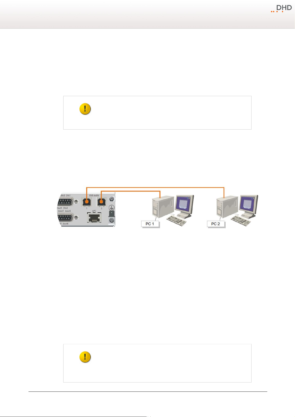
There are two options to use the USB audio port. Option 1 - Each USB audio port is connected to a separate PC and option
2 - both USB audio ports are connected to a single PC. You can find more information about these two options in the
following sections.
9.1 Option 1 - Each USB connected to a seperate PC
21
In this case, each USB audio port is connected to a separate PC.
Two PCs, each connected to an USB audio port of the 52-1330.
The following operation systems are supported for this option:
· Microsoft™ Windows™ 98SE/Windows Me (For Windows 98SE and Windows Me, the HID function is not fully functional
with the default class driver.)
· Microsoft Windows 2000 Professional
· Microsoft Windows XP Home/Professional (For Windows XP, use the latest version of the USB audio driver available
from the Windows Internet site, or apply Service Pack 1 or later.
· Microsoft Windows Vista™ Business
· Microsoft Windows 7™ Professional
To use the USB audio input or output, just connect one of the USB audio ports of the 52-1330 with an empty USB port on
your PC. Please use a standard USB cable for this connection. The USB audio port will be identified as an "USB Audio
CODEC" in windows.
9.2 Option 2 - Both USB connected to single PC
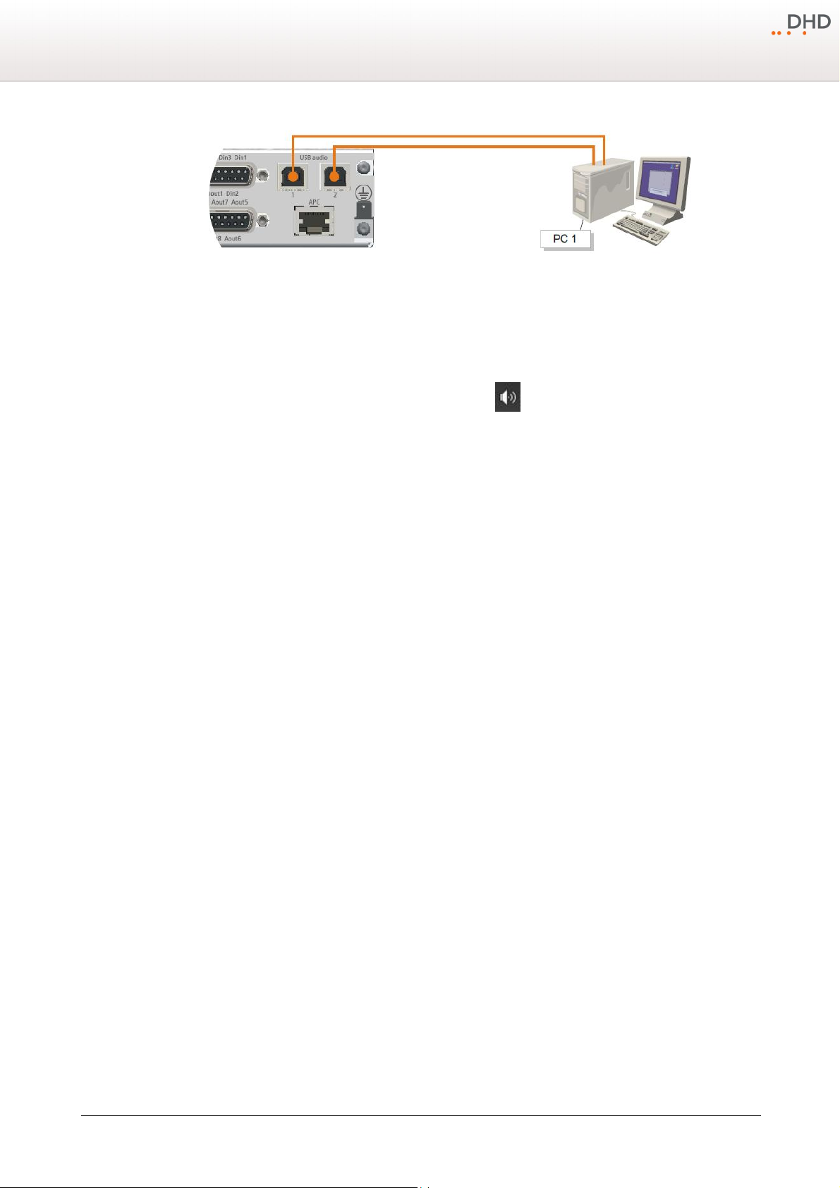
In this case, the two USB audio ports are connected to a single PC.
Specifications and design are subject to change without notice. The content of this document is for information only. The information presented in this document does not form part
of any quotation or contract, is believed to be accurate and reliable and may be changed without notice. No liability will be accepted by the publisher for any consequence of its use.
Publication thereof does neither convey nor imply any license under patent rights or other industrial or intellectual property rights.
Version 1.2.0 - 04.02.2013
Page 25
22
Series 52 - 52/DX Compact Mixing Console Manual
A single PC connected to the 2 USB audio ports of the 52-1330.
Each USB port will be identified as an "USB Audio CODEC". To use these two USB audio ports properly you should rename
these two USB Audio Devices. To connect the 52-1330 to your PC and rename the USB audio devices, follow these steps:
1. Connect USB port 1 on 52-1330 with an unused USB port on your PC with an standard USB cable.
2. In the Notification area next to the windows clock, right-click on the icon.
3. In the context menu select
4. On the
Properties
5. On the General tab, in the text box next to the speaker symbol, enter a distinctive name for the USB audio device, for
example 1330-1. Click OK.
6. Unplug the USB connection from USB port 1 on the 52-1330.
7. Connect the USB port 2 with a second USB cable to another USB port on your PC.
8. In the
Speakers Properties
9. On the
for example 1330-2. Click OK.
10.Reconnect the first USB cable to the USB port 1 of the 52-1330. In the
As long as the USB audio devices are connected to the same USB port on the PC, they can be identified unambiguously in
windows.
Playback
window opens.
Sound
General
window, on the
Playback devices
tab, select
window opens.
tab, in the text box next to the speaker symbol, enter a distinctive name for the USB audio device,
Speakers-USB Audio CODEC
Playback
. The
tab, select
9.3 Internal sample rate converter
Sound
Speakers-USB Audio CODEC
window opens.
and click
Sound
Properties
window both devices are available now.
and click
. The
Speakers
Properties
. The
By default, the input and output sample rate converter of the USB audio ports are set to
rate of the PC can be chosen absolutely independent from the sample rate of the 52/DX.
Example:
The PC is using a sample rate of 44.1 kHz, while the 52/DX is running with a sample rate of 48 kHz. With default SRC
values the input signal from the PC to the 52-1330 will be converted from 44.1 kHz to 48 kHz. The output signal from the
52-1330 to the PC will be converted from 48 kHz to 44.1 kHz.
© 2013 DHD Deubner Hoffmann Digital GmbH
Specifications and design are subject to change without notice. The content of this document is for information only. The information presented in this document does not form part
of any quotation or contract, is believed to be accurate and reliable and may be changed without notice. No liability will be accepted by the publisher for any consequence of its use.
Publication thereof does neither convey nor imply any license under patent rights or other industrial or intellectual property rights.
. Because of that, the sample
ON
Page 26
10 Configuration
In general, the 52/DX is preconfigured with a default configuration and will work with default values.
To customise the configuration of your 52/DX mixing console, DXConfig software is required. You'll find this software on
the CD, delivered with your mixing console.
The DXConfig software is a Windows program that does not require any additional dynamic libraries (DLL files) or other
files. For installation, simply copy the program file to the hard drive. To load the software, double-click on the
. To remove the program, delete the
exe
When opening DXConfig, another software application is loaded automatically: DHD Communication Server (DHDCS).
DHDCS filters TCP/IP and UDP packets from the network that are transferred to and from DHD devices and prepares them
for several software applications. Please find detailed information on DHDCS in the Application Software Manual of the
RM4200D.
You can use DXConfig without any hardware connected, for example for changing or checking configurations offline.
Normally, the configuration PC is connected with the corresponding DHD system using the TCP/IP protocol via Ethernet.
DXConfig.exe
Configuration
DXConfig.
.
23
To configure your 52/DX device double-click on the
load your configuration into the 52/DX device (see Transfer Menu). Now the new configuration is available in the device
and can be used.
In the following sections all configurable options are explained.
DXConfig.exe.
After customizing the default values, you have to
Version 1.2.0 - 04.02.2013
Specifications and design are subject to change without notice. The content of this document is for information only. The information presented in this document does not form part
of any quotation or contract, is believed to be accurate and reliable and may be changed without notice. No liability will be accepted by the publisher for any consequence of its use.
Publication thereof does neither convey nor imply any license under patent rights or other industrial or intellectual property rights.
Page 27
24
Note
In DXConfig, only one device file can be shown at the same time. It is possible
to open the DXConfig software several times on a PC to be able to edit several
devices at the same time.
Series 52 - 52/DX Compact Mixing Console Manual
10.1 Program Menus
In this section of the manual, the menus and the commands of the DXConfig software are described.
10.1.1 File Menu
10.1.1.1 New Device
A new device is created. The device contains only the default values.
This command can also be executed by clicking in the toolbar.
If a device file is already open, it can be saved before creating the new file.
10.1.1.2 Open Device
An already existing device file is opened.
You can execute this command also by clicking in the toolbar or by pressing
If a device file is open already, it can be saved before opening the new file.
10.1.1.3 Save Device
The current device is saved.
The command can also be executed by clicking in the toolbar or by pressing
10.1.1.4 Save Device as
The current device file is saved with a different name. The program suggests the current name in the
The new device file is available for further configuration directly after saving, the original file is closed.
You are automatically working with the new created file after saving.
Ctrl+O
Ctrl+S
.
on the keyboard.
Save
dialog box.
© 2013 DHD Deubner Hoffmann Digital GmbH
Specifications and design are subject to change without notice. The content of this document is for information only. The information presented in this document does not form part
of any quotation or contract, is believed to be accurate and reliable and may be changed without notice. No liability will be accepted by the publisher for any consequence of its use.
Publication thereof does neither convey nor imply any license under patent rights or other industrial or intellectual property rights.
Page 28
10.1.1.5 History
Note
A history entry can not be changed or deleted, once the entry was saved.
Configuration
25
Using the
History
function in the
menu of DXConfig, you can log modifications of the configuration. This way,
File
you can later reproduce, which user made which modifications of the system at which time.
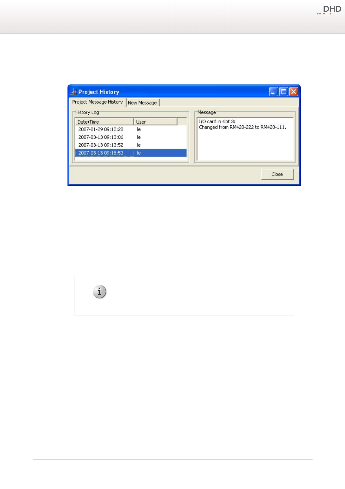
Project History, logging modifications during configuration.
In the
File
tab, in the
menu click
History
History Log
; the
Project History
window opens. On the
Project Message History
area, the single entries are shown with date and time, as well as the login name of the user
(Microsoft Windows Login) who created the entry. DXConfig itself logs some processes, for example when and by who a
configuration was originally created. Other changes that seem important to you can be inserted manually.
To do this, select the
Clear
To show a message, on the
then shown in the
10.1.1.6 Exit
This command quits the DXConfig software. A message prompting you to save an open device file is shown if its current
state is not saved yet.
New Message
tab, type the new message and click
to delete the whole text that is entered in the
Project Message History
Message
box.
Enter Message
tab, select an entry in the
box.
to log the text in the history. Click
Save
History Log
list. The text is
Specifications and design are subject to change without notice. The content of this document is for information only. The information presented in this document does not form part
of any quotation or contract, is believed to be accurate and reliable and may be changed without notice. No liability will be accepted by the publisher for any consequence of its use.
Publication thereof does neither convey nor imply any license under patent rights or other industrial or intellectual property rights.
Version 1.2.0 - 04.02.2013
Page 29
26
Note
The functions that can be triggered from the maintenance window do not affect
an open device file. If you want to access maintenance functions in SXConfig
only, it is not necessary to load a device file.
Series 52 - 52/DX Compact Mixing Console Manual
10.1.2 View Menu
10.1.2.1 Maintenance Window
Using this command, you open the maintenance window. In this window, you have direct access to the modules of DHD
systems, important settings and services. These functions are of a great variety and are therefore dealt with in an own
chapter. (See Maintenance Window — Servicing Modules)
You can also open or enable the maintenance window by pressing
10.1.2.2 Key Functions
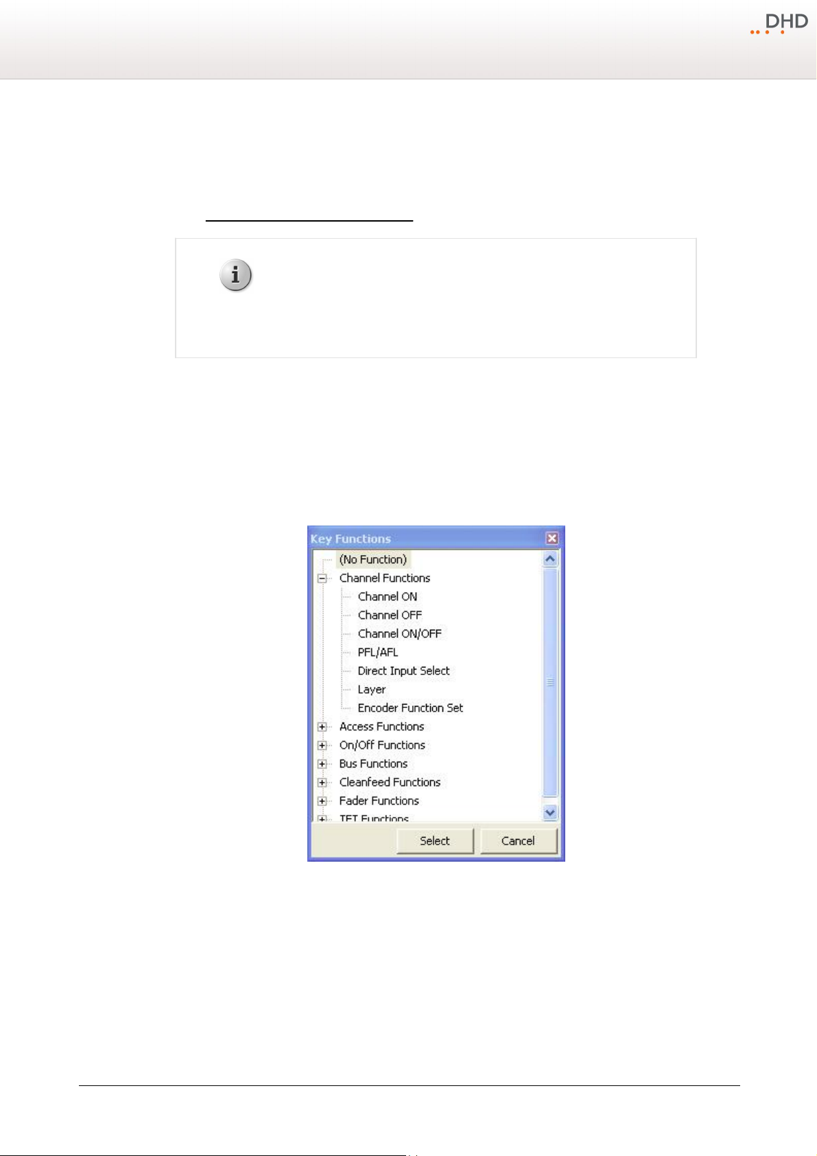
This window shows all
must be selected on the
You can open or enable the window also by pressing
Key Functions
Console
tab. The key functions are divided into groups according to their characteristics.
.
F7
that are available for configuring the keys or TFT buttons of the device. A key
.
F8
Window Key Functions, selecting key functions.
10.1.2.3 Logic Sources
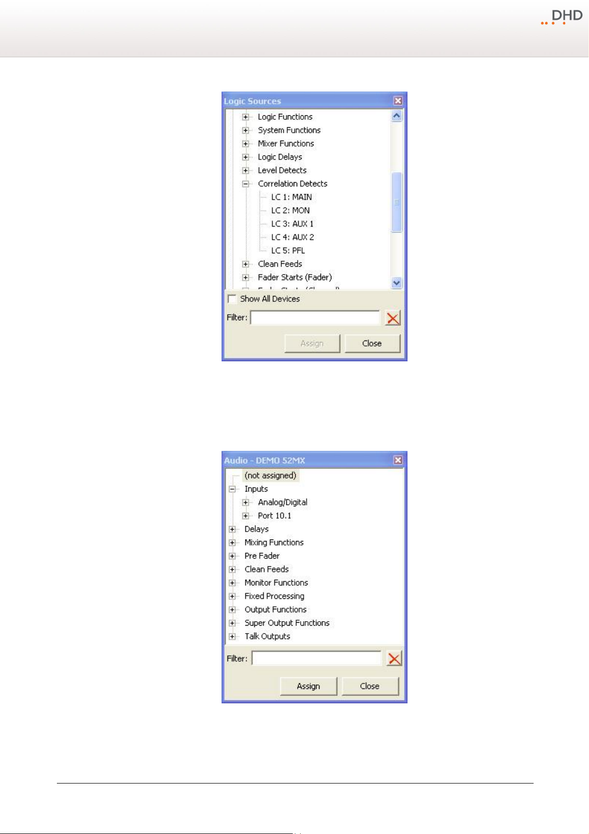
This window shows all internal logic signals that are available for configuring the device. The logic sources are grouped
according to their characteristics.
You can also open this window by pressing
© 2013 DHD Deubner Hoffmann Digital GmbH
Specifications and design are subject to change without notice. The content of this document is for information only. The information presented in this document does not form part
of any quotation or contract, is believed to be accurate and reliable and may be changed without notice. No liability will be accepted by the publisher for any consequence of its use.
Publication thereof does neither convey nor imply any license under patent rights or other industrial or intellectual property rights.
F5
.
Page 30
Configuration
27
10.1.2.4 Audio Sources
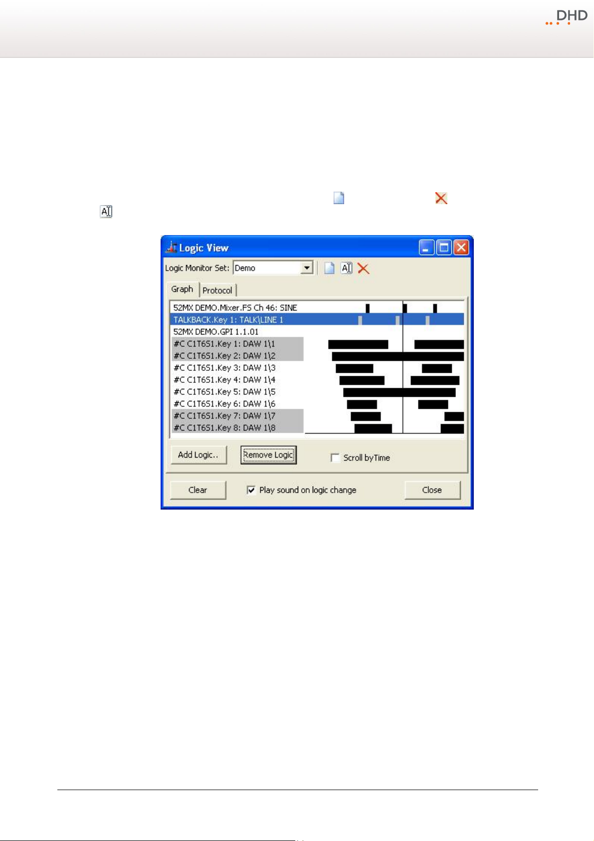
This window shows all internal audio signals that are available for configuring the device. The audio signals are grouped
according to their characteristics.
Window Logic Sources, selecting logic sources.
Audio, selecting audio sources.
On the internal TDM bus, the following audio channels are available: inputs, delays, mixing functions (sums, groups, Aux
busses) pre-fader signals (fader channel after input processing), clean feeds (n-1 busses), monitor functions, fixed
Version 1.2.0 - 04.02.2013
Specifications and design are subject to change without notice. The content of this document is for information only. The information presented in this document does not form part
of any quotation or contract, is believed to be accurate and reliable and may be changed without notice. No liability will be accepted by the publisher for any consequence of its use.
Publication thereof does neither convey nor imply any license under patent rights or other industrial or intellectual property rights.
Page 31
28
Series 52 - 52/DX Compact Mixing Console Manual
processing, output functions, super output functions and talk outputs.
You can also open this window by pressing
10.1.2.5 Watches - Logic Monitor
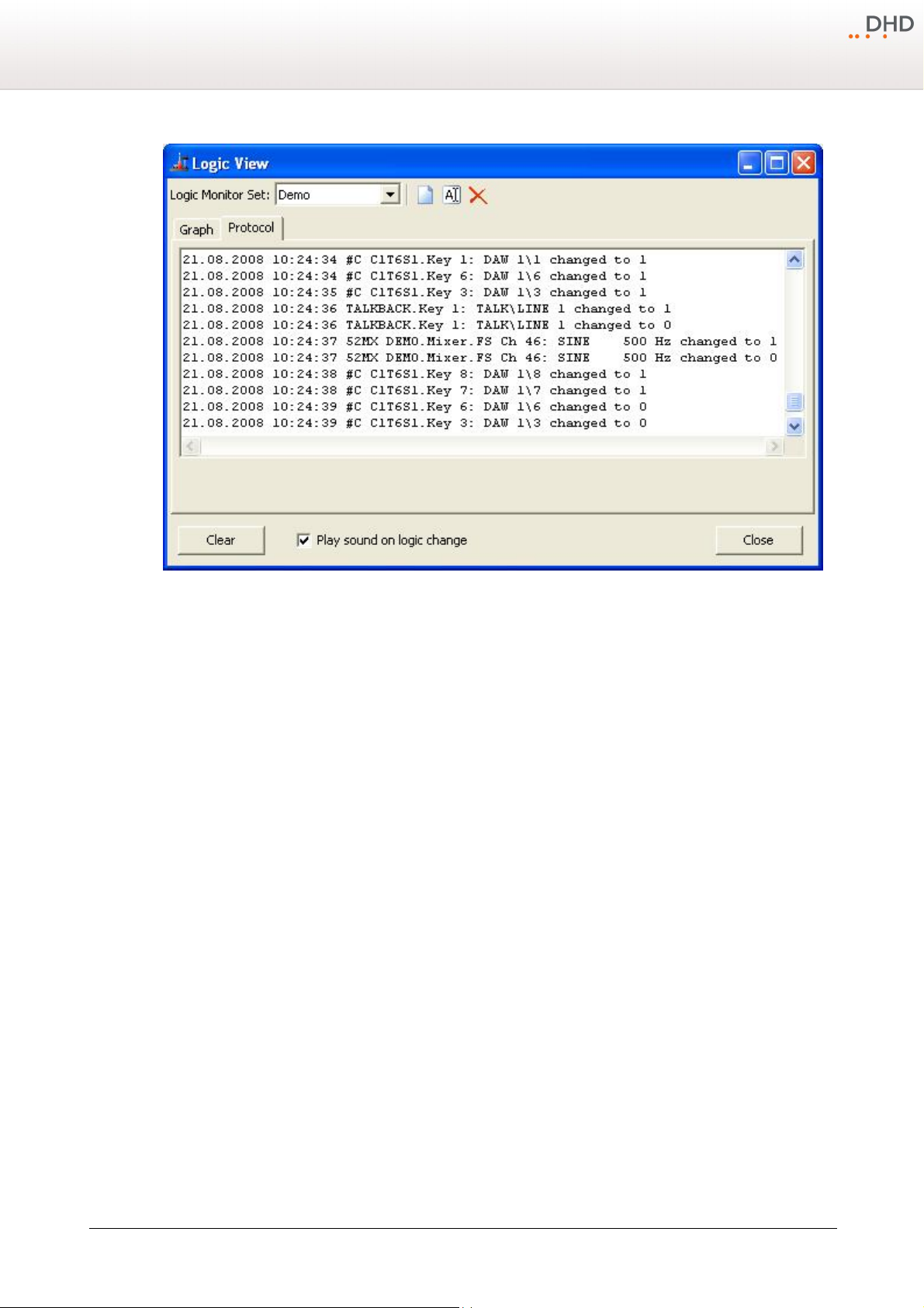
With the
Logic View
For clearness, you can create several views including logics. Click to generate a new view, deletes a view and with
you can rename it. All views are available in the
window you can monitor all logics of the currently loaded DXConfig device.
F6
.
Logic Monitor Set
list.
Logic states, shown in a timeline.
The
new logic to the view.
tab shows all logics in a time line. Click
Graph
Remove Logic
Add Logic
to open the
Logic Sources
window and to add a
deletes the selected logic from the list. On the left hand side of the window you
can find the labels of all inserted logics. The graphical view next to these labels shows the state of the logics at different
times. The intervals of the on/off periods are not related to the time, but to each other. For example you can see that
was activated first, afterwards
1\1
DAW 1\2
was activated and so on. All labels with a grey background are currently
DAW
active.
If you select the
Scroll by Time
check box, the history is not shown and you will only see, which logics are currently
active. Moreover, it is possible to clear the history and to activate a sound that signalises the change of logic states.
Instead of the graphical view, you can choose the
Protocol
tab. Here, you can find the changes of the logic states and
the absolute time the changes did occur.
© 2013 DHD Deubner Hoffmann Digital GmbH
Specifications and design are subject to change without notice. The content of this document is for information only. The information presented in this document does not form part
of any quotation or contract, is believed to be accurate and reliable and may be changed without notice. No liability will be accepted by the publisher for any consequence of its use.
Publication thereof does neither convey nor imply any license under patent rights or other industrial or intellectual property rights.
Page 32
Configuration
29
10.1.3 Transfer Menu
Connecting the Configuration PC and the Device
To load a Config from a device to the DXConfig software or write it back to the device after modifying it, the configuration
data has to be exchanged between the configuration PC and the devices. This is done by an Ethernet connection using
TCP/IP.
The commands
respectively. In the DXConfig software, you can choose between different options, how the configuration PC can exchange
data with the device.
Select the command for up- or download. After that, the
both commands:
Load to Device
Logic states, shown in a list.
and
Load from Device
DHD Connection Dialog
load and store a Config to and from the device
window opens that is identical for
Version 1.2.0 - 04.02.2013
Specifications and design are subject to change without notice. The content of this document is for information only. The information presented in this document does not form part
of any quotation or contract, is believed to be accurate and reliable and may be changed without notice. No liability will be accepted by the publisher for any consequence of its use.
Publication thereof does neither convey nor imply any license under patent rights or other industrial or intellectual property rights.
Page 33
30
Note
If no UDP packets are transferred between the DXConfig software and the
devices, the list of all available DHD systems is not shown in the
DHD
Connection Dialog
. In this case, you have to know exactly, which IP
addresses belong to which device, and enter them manually in the
Fixed IP
box.
Series 52 - 52/DX Compact Mixing Console Manual
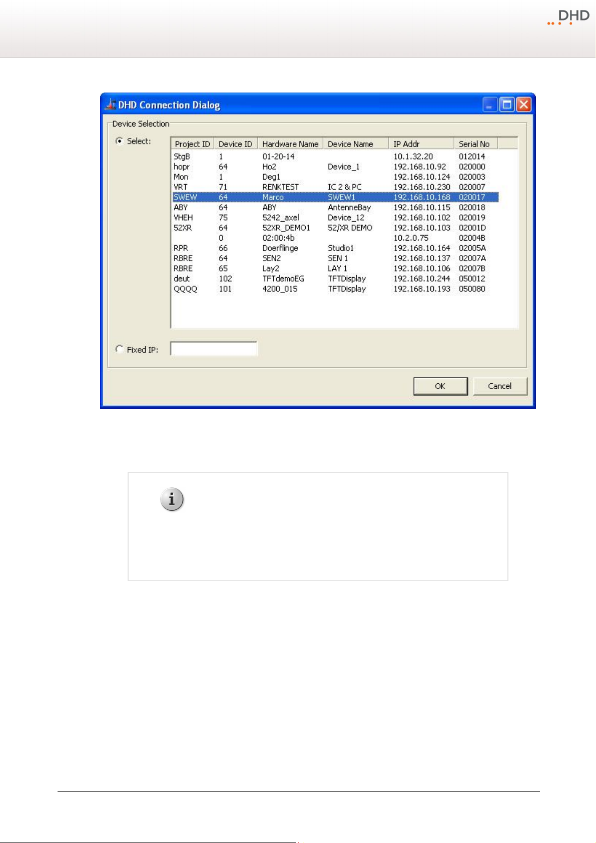
DHD Connection Dialog window for connections with the device.
The devices use the UDP protocol to announce their availability in the network. This requires that UDP packets can be
transferred between the DSP frames and the configuration PC. This is not always possible in all networks.
If the configuration PC and the devices can communicate via the UDP protocol, the list in the
window shows all available systems. You can now select the desired destination from the list.
After transferring a Config to a device, in the status bar of the DXConfig window the message
DHD Connection Dialog
Project modified
shown. During the transfer, a time stamp is set in the file that is also transferred to the device. According to this time
stamp, the DXConfig software can recognize, whether the Config in the device differs from the one in the file. The data
stamp of the file or the time of the last transfer are shown under
the Config has never been transferred to a device,
no timestamp
<Device>/Options
is shown.
in the
Last changed
box. If
There are the following options for setting up a connection:
is
·
: In the list, all devices connected to the IP network segment are listed. This list is created automatically via
Select
UDP broadcast messages that are received from the devices. For each device, the appropriate project ID, device ID and
the hardware and device name are shown, as well as the IP address. The
number of the device which is identical with the company-specific bytes of the Ethernet MAC address of the device.
Select the desired device by mouse clicking.
© 2013 DHD Deubner Hoffmann Digital GmbH
Specifications and design are subject to change without notice. The content of this document is for information only. The information presented in this document does not form part
of any quotation or contract, is believed to be accurate and reliable and may be changed without notice. No liability will be accepted by the publisher for any consequence of its use.
Publication thereof does neither convey nor imply any license under patent rights or other industrial or intellectual property rights.
Serial No
column shows the serial
Page 34
Configuration
IP address of DXConfig-PC
192.168.010.057
IP address of device
192.168.010.058
Subnet mask
255.255.255.0
Warning
Loading a new Config overwrites a Config already existing in the device.
Therefore, if in doubt, save the current Config before making any changes using
the
Load from Device
command and save it to a file.
31
·
Fixed IP
: Here, you can enter the IP address of the device directly. This may be necessary if no UDP packets can be
received, if the configuration PC and the device are located in different network segments. For remote servicing of
systems this option might be helpful as well.
If you want to connect the device directly to the configuration PC with an ethernet cable, a twisted ethernet patch cable
(X-cable, cross cable) has to be used. Assign static IP addresses on both sides (no DHCP). The first 3 bytes of the address
must be identical, the last byte must differ, like the following example:
Note on the Configuration of IP addresses
Each device needs an unambiguous IP address that is either set statically or assigned by a DHCP server. The appropriate
setting can be found under
Network Configuration in the Maintenance Window
. (See also Maintenance
Window - Servicing Modules)
If the devices are not constantly connected to an IP network, you should use static IP addresses. Do not assign any of the
IP addresses twice. Don't operate devices with DHCP enabled if no DHCP server is available on the network.
10.1.3.1 Load to Device
This command copies the current Config from the DXConfig software to the selected device. To do this, use the command
Load to Device
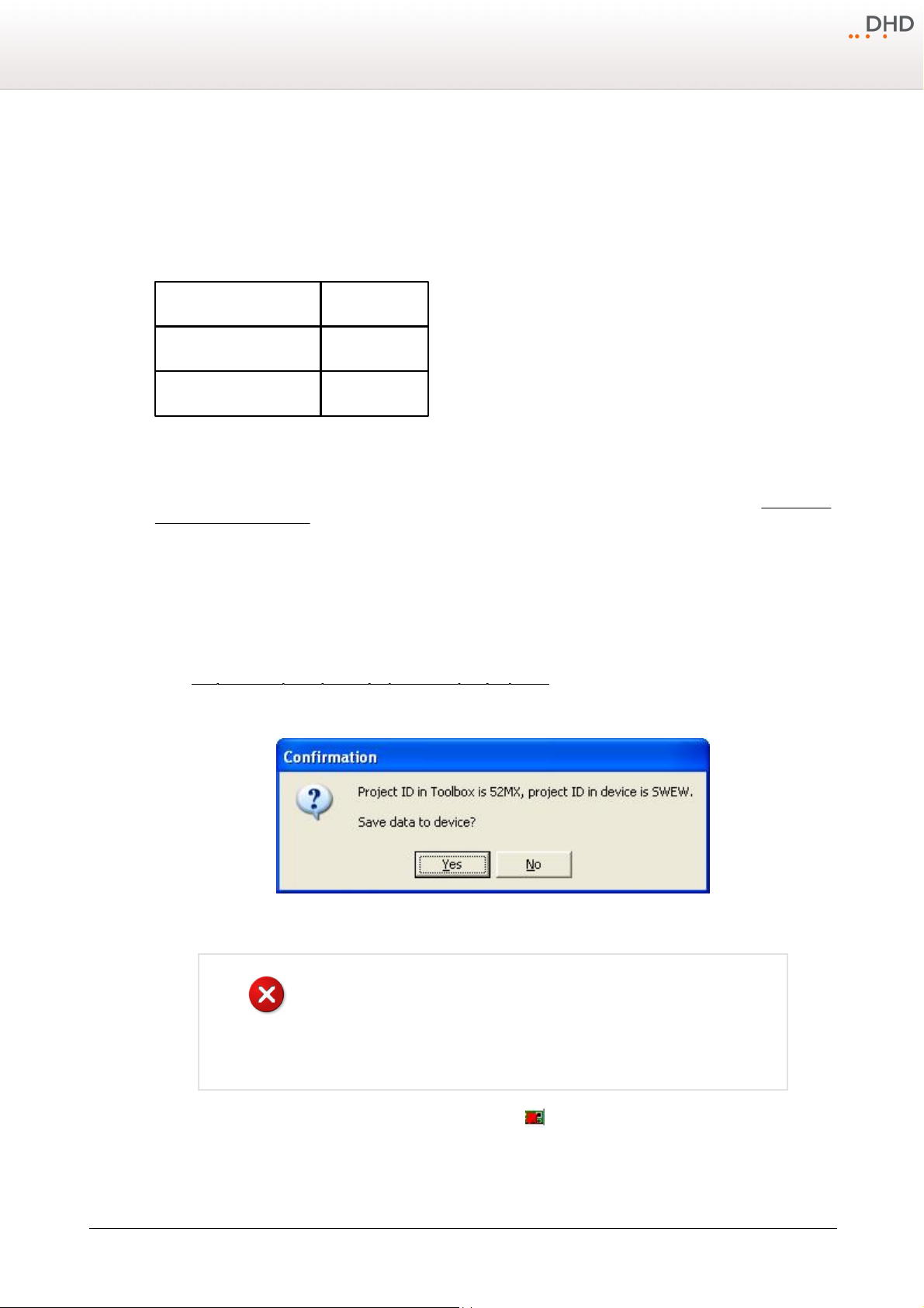
figure DHD Connection Dialog window for connections with the device) After confirming the selection, the new Config is
transferred. If the name of the device in the project and the one of the device selected in the network should not be
identical, the following message is shown:
. The
DHD Connection Dialog
window opens, in which you can select the desired device. (See
Confirmation window if the project IDs in the DXConfig software and the
device are not identical when uploading a Config.
The command
Specifications and design are subject to change without notice. The content of this document is for information only. The information presented in this document does not form part
of any quotation or contract, is believed to be accurate and reliable and may be changed without notice. No liability will be accepted by the publisher for any consequence of its use.
Publication thereof does neither convey nor imply any license under patent rights or other industrial or intellectual property rights.
Load to Device
can also be executed by clicking in the toolbar.
Version 1.2.0 - 04.02.2013
Page 35
32
Note
If the device you are downloading a Config from is already included in the
project, it is automatically selected in the
DHD Connection Dialog
. This
requires identical values for project ID and device ID both in the project and the
device itself.
Warning
Be aware that changes of device caused by downloads can not be undone, as
soon as the device file is saved. Therefore, for safety reasons, always work with
copies of the original device files.
Series 52 - 52/DX Compact Mixing Console Manual
10.1.3.2 Load from Device
This command loads a Config from a device to the DXConfig software. In the
must select the corresponding device. (See figure DHD Connection Dialog window for connections with the device)
Alternatively, you can create an new device. Then, load the Config into this empty device.
In general, it is always better to save the current Config of a device as device file. If other changes become necessary,
load the device file again and modify it. After that, load the new Config to the corresponding devices. This way, the device
file is always up to date and is available as a backup for the configuration data in the devices at the same time.
DHD Connection Dialog
window you
You can execute the command
10.1.4 Options Menu
With the settings in the
have no effect on the configuration of the devices.
10.1.4.1 Configuration
After selecting
the following table.
You can select this option also by clicking in the toolbar.
Configuration
Load from Device
Options
menu, only options are set that affect the operation of the DXConfig software. They
, the
Toolbox Configuration
also by clicking in the toolbar.
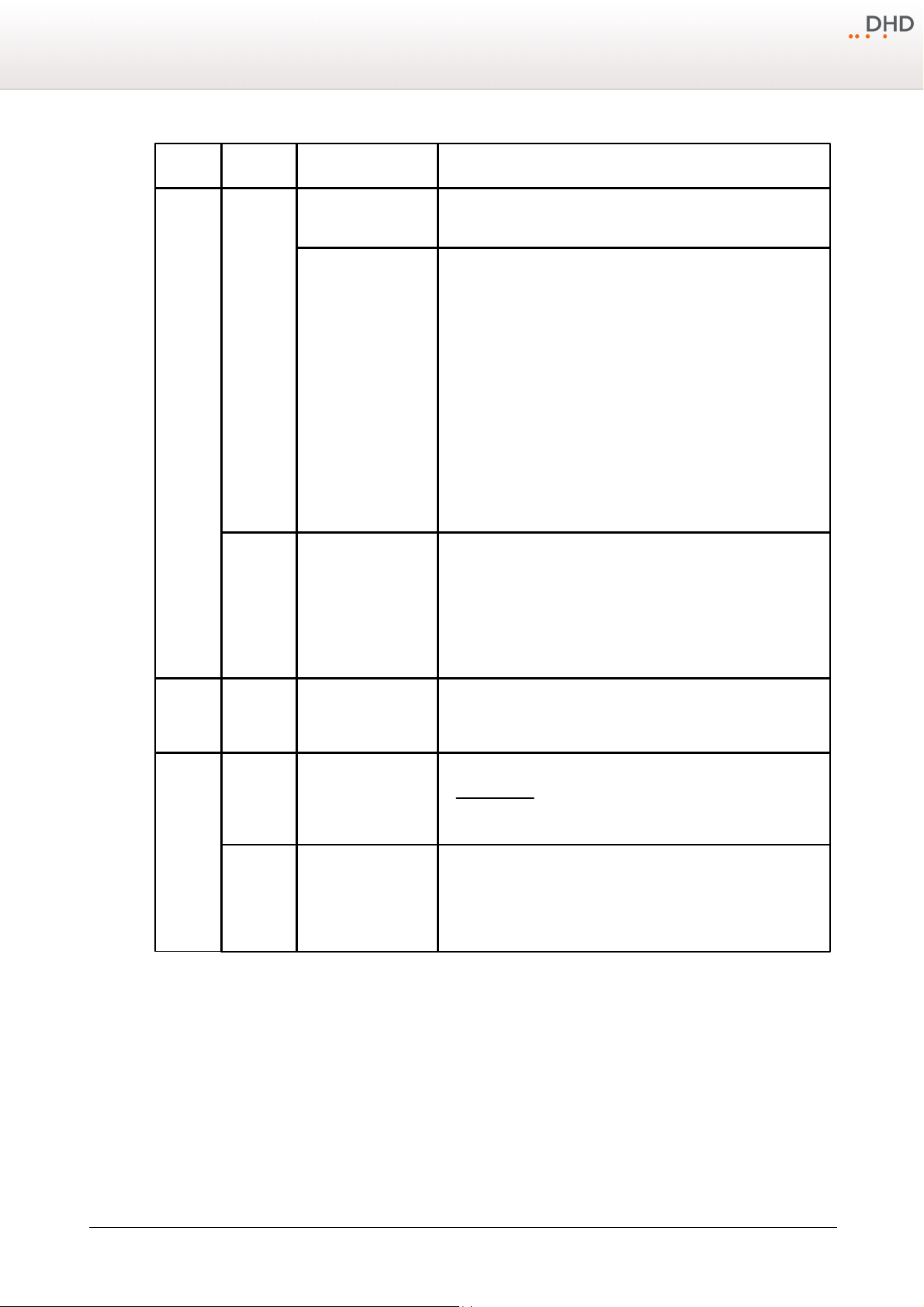
window opens. The options are explained in detail in
© 2013 DHD Deubner Hoffmann Digital GmbH
Specifications and design are subject to change without notice. The content of this document is for information only. The information presented in this document does not form part
of any quotation or contract, is believed to be accurate and reliable and may be changed without notice. No liability will be accepted by the publisher for any consequence of its use.
Publication thereof does neither convey nor imply any license under patent rights or other industrial or intellectual property rights.
Page 36
Configuration
tab
area
option
description
Files
Project Files
Save
Backup Levels
· Define here, how many backup generations shall be created. (min.
=0, max.=100)
Auto Save each
· If this check box is selected, the software creates backups of the
project file automatically.
· The number of backup files can be set in the
Backup Levels
box. If the last file is written, the first is overwritten when saving
the next time. This way, it is lost!
· The desired interval between two backups can be entered in the
Auto Save each
(min.=0 minutes, max.=100 minutes) box.
· The created backup files have the number of the backup in their
extensions, for example
.sxc.1
. The higher this number is, the
newer is this file. If you want to use such a file in the DXConfig
software again, previously you have to change its extension to
.
dxc
again.
File Menu
Show recently used files
list
· If this check box is selected, only the defined number of recently
opened projects is offered as a quick start option in the
File
menu.
· The desired number of entries can be defined in the
Show
recently used files list
box. (min.=0 entries, max.=100
entries)
View
Navigator
View follows selected
object automatically
· By selecting this check box, the content of the navigator
automatically adapts to the options and functions that are currently
edited.
Audio and
Logic
Sources
Audio and
Logic Tree
Hide sources without
label
· This option influences the
Audio sources
window. (See also
Audio Sources) If it is enabled, audio sources with deleted labels
on the
I/O Settings
tab, are deactivated in the
Audio
Sources
window.
Assignment
Automatically select
next item
· Select this check box to work quicker when defining the Output
Routing on the
I/O Settings
tab. In this case, the DXConfig
software selects the following output automatically when assigning
audio signals to the outputs - in the output list as well as in the list
of audio signals in the
Audio Sources
window.
33
10.1.5 Help Menu
10.1.5.1 About
Specifications and design are subject to change without notice. The content of this document is for information only. The information presented in this document does not form part
of any quotation or contract, is believed to be accurate and reliable and may be changed without notice. No liability will be accepted by the publisher for any consequence of its use.
Publication thereof does neither convey nor imply any license under patent rights or other industrial or intellectual property rights.
If you select
Here, the date of creation of the software and the version of the used DXConfig are shown, for example
7.1.4.0
The version number of the DHDCS that is included in DXConfig is also shown in this window.
Please always mention the complete version name when asking for servicing.
About
, the
Information
window opens.
Version
Version 1.2.0 - 04.02.2013
Page 37
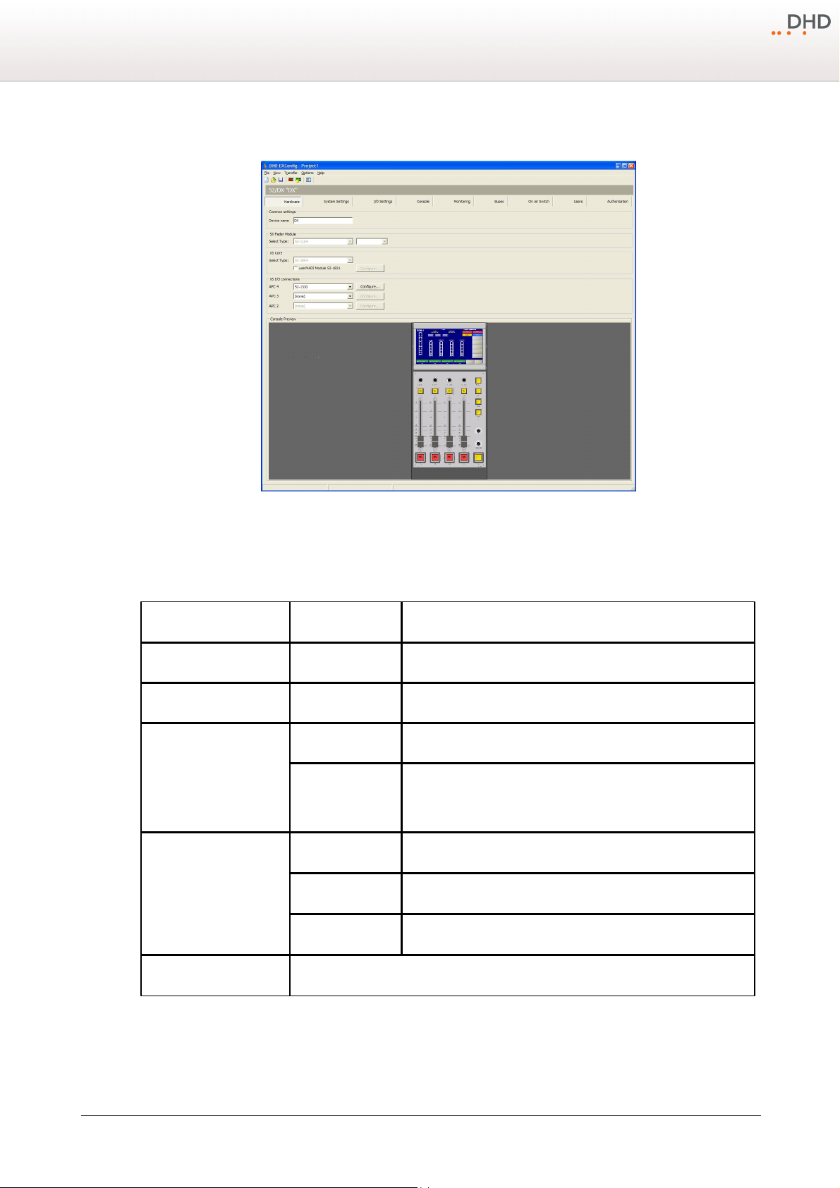
34
area
option
description
Common settings
Device name
Please enter a distinctive device name for this 52/DX mixing console.
SX Fader Modules
Select Type
Not available for 52/DX devices.
XS Core
Select Type
52-1804 is preselected and can not be changed.
use MADI Module
52-1821
If your XS core is equipped with a MADI module 52-1821, please
select this check box to enable the inputs and outputs for the
I/O
Settings
tab.
XS I/O connections
APC 4
Select an I/O type or set the value to
(none)
. Default is
52-1330
.
APC 3
Select an I/O type or set the value to
(none)
. Default is
(none)
.
APC 2
Select an I/O type or set the value to
(none)
. Default is
(none)
.
Console Preview
Shows a preview of the configured control module
Series 52 - 52/DX Compact Mixing Console Manual
10.2 Hardware
On the
Hardware
DXConfig Software - Hardware
page you can set, which 52/DX modules are connected to your system.
© 2013 DHD Deubner Hoffmann Digital GmbH
Specifications and design are subject to change without notice. The content of this document is for information only. The information presented in this document does not form part
of any quotation or contract, is believed to be accurate and reliable and may be changed without notice. No liability will be accepted by the publisher for any consequence of its use.
Publication thereof does neither convey nor imply any license under patent rights or other industrial or intellectual property rights.
Page 38
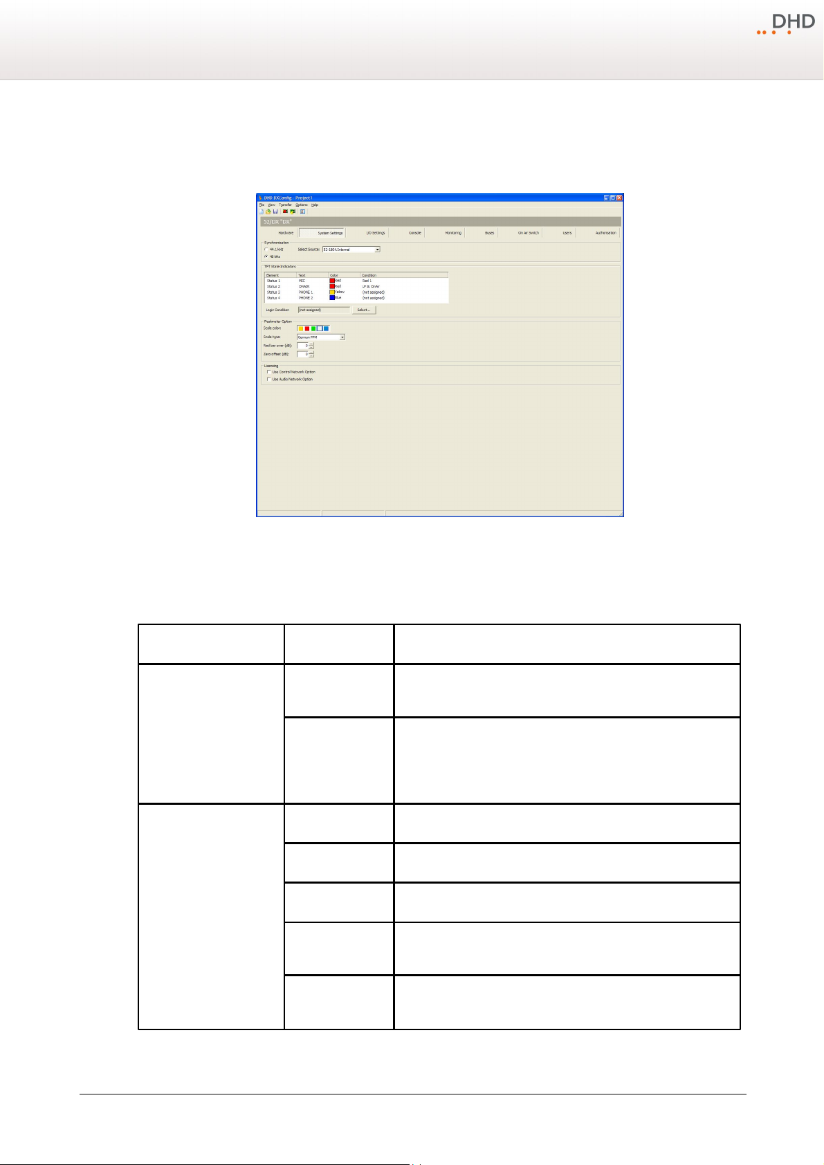
10.3 System Settings
area
option
description
Synchronisation
44.1 kHz / 48 kHz
Select here, which sample rate should be set for internal
synchronisation.
Select Source
Select in this list, which sync source should be used:
· 52-180X.Internal - internal clock
· 52-180X.GA1 - Gigabit Audio-signal (optional)
· 52-180X.BNC Wordclock (rising edge) (optional)
· 52-180X.BNC Wordclock (falling edge) (optional)
· 52-180X.BNC AES/EBU (optional)
TFT State Indicators
Element
All four available status transparents are shown in this list.
Text
Double-click on the default text to change it.
Color
Double-click on the default color to change it.
Condition
Double-click on the default logic condition, the Logic sources window
opens. Select the desired logic and click assign.
Logic Condition
Select a State indicator from the list and click
Select
to assign an
other logic source from the logic sources window.
Configuration
35
On the
System Settings
In the following table you can find the descriptions for these options.
page, you can configure general options for your 52/DX.
DXConfig Software - System Settings
Specifications and design are subject to change without notice. The content of this document is for information only. The information presented in this document does not form part
of any quotation or contract, is believed to be accurate and reliable and may be changed without notice. No liability will be accepted by the publisher for any consequence of its use.
Publication thereof does neither convey nor imply any license under patent rights or other industrial or intellectual property rights.
Version 1.2.0 - 04.02.2013
Page 39
36
area
option
description
Peakmeter Option
Scale Color
Select the colour of the peak program meter on the TFT display. The
selected colour is used for all peak program meters of the 52/DX.
Scale Type
Select your preferred type of peak meter scale.
Red Bar Over (dB)
Select the decibel value at which the level bar turns red for signaling
a critical level area. (-20 dB to +20 dB)
Zero Offset (dB)
Select the decibel value, which will be added to the level bar to
adjust the shown signal level.
Licensing
Use Control Network
Option
To enable the features of the XC/XS Core Control Networking licence
select this check box.
Important
The configuration can only
be loaded into the device,
if the corresponding licence
key is assigned to this
device.
Use Audio Network
Option
To enable the features of the XC/XS Core Audio Network licence
select this check box.
Important
The configuration can only
be loaded into the device,
if the corresponding licence
key is assigned to this
device.
Series 52 - 52/DX Compact Mixing Console Manual
© 2013 DHD Deubner Hoffmann Digital GmbH
Specifications and design are subject to change without notice. The content of this document is for information only. The information presented in this document does not form part
of any quotation or contract, is believed to be accurate and reliable and may be changed without notice. No liability will be accepted by the publisher for any consequence of its use.
Publication thereof does neither convey nor imply any license under patent rights or other industrial or intellectual property rights.
Page 40
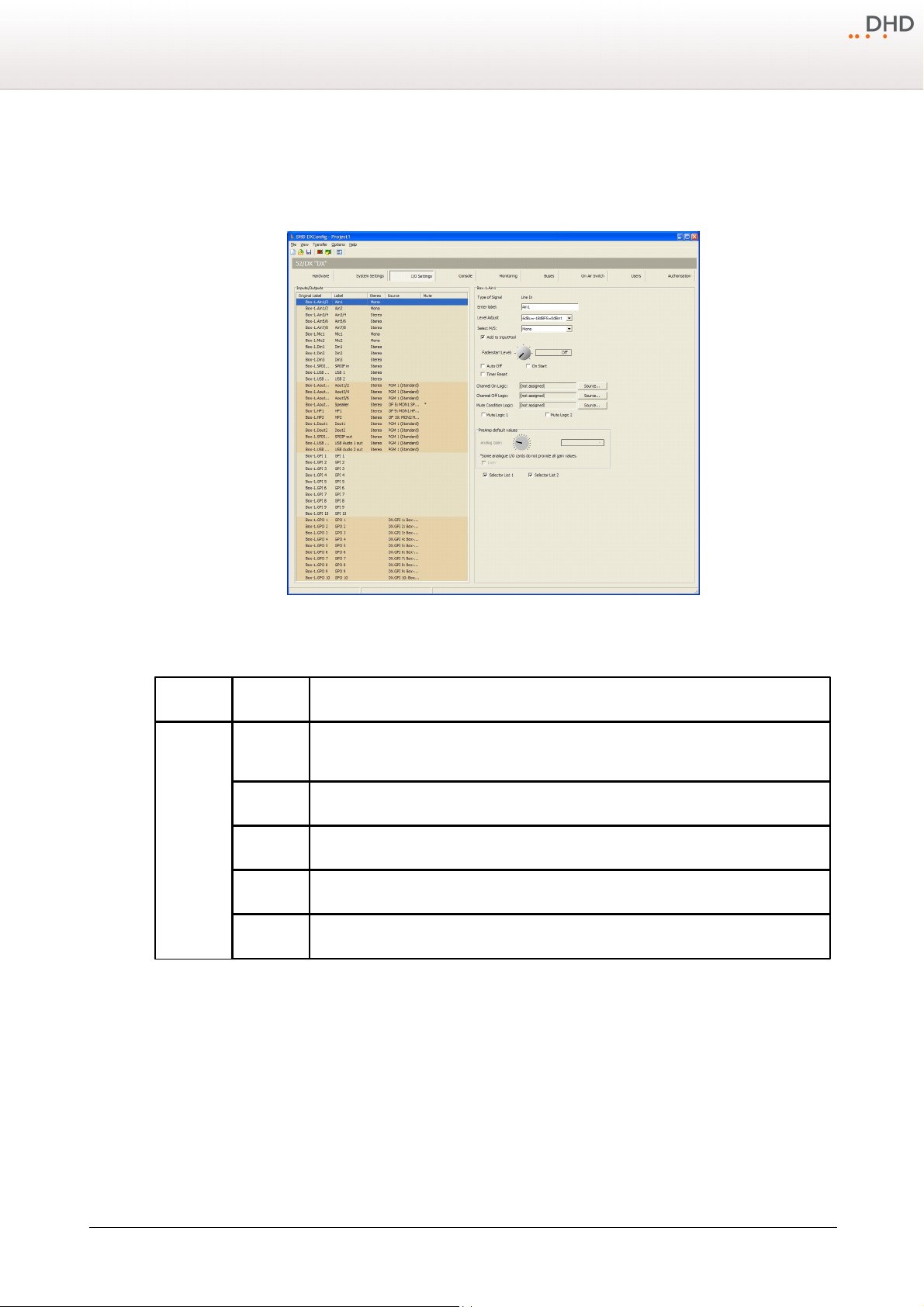
10.4 I/O Settings
area
option
description
Inputs/
Outputs
Original
Label
This column shows the internal label which is generated in that scheme: <module type->.
<port label>
Label
Individual Label, double-click on the label and change the current name.
Stereo
Indicates if the signal is mono or stereo.
Source
Shows the assigned audio/logic source for input and output.
Mute
Shows, that a Mute Logic is assigned to an output.
Configuration
37
On the
I/O Settings
for any input or output.
page, you can configure different options for each input and output. Not all options are available
DXConfig Software - I/O Settings
In the following table you can find the descriptions for these options.
Specifications and design are subject to change without notice. The content of this document is for information only. The information presented in this document does not form part
of any quotation or contract, is believed to be accurate and reliable and may be changed without notice. No liability will be accepted by the publisher for any consequence of its use.
Publication thereof does neither convey nor imply any license under patent rights or other industrial or intellectual property rights.
Version 1.2.0 - 04.02.2013
Page 41
38
area
option
description
IOModule-X.
<port>
Audio Inputs
Type of
Signal
Shows the general signal type of the port.
Enter Label
Enter a distinctive name for the selected input.
Level Adjust
Choose the headroom for each input from the corresponding drop-down menu. The shown
values always refer to the devices internal default level of 0 dBint.
Select M/S
Select, if the signal is mono or stereo.
Sample Rate
Converter
Select from the drop down menu, if the sample rate converter is activated (On) or
deactivated (
Off
) for this input.
Add to Input
Pool
Select this check box to make this signal available for a channel on the console
Fader Start
Level
Select a level, which sets the fader start logic to on.
Auto Off
By closing the fader, the channel is automatically switched
OFF (ON
key is deactivated).
On Start
The faderstart is only activated and deactivated by pushing the On/Off key, not by moving
the fader.
Timer Reset
If this check box is selected, opening this fader will reset and start the
Auto
timer of the
stopwatch.
Channel On
Logic
Select a Logic Function from the
Logic Sources
window, which sets the channel to ON.
You can choose, for example a GPI to open a channel.
Channel Off
Logic
Select a Logic Function from the
Logic Sources
window, which sets the channel to OFF.
You can choose, for example a GPI to close a channel.
Series 52 - 52/DX Compact Mixing Console Manual
© 2013 DHD Deubner Hoffmann Digital GmbH
Specifications and design are subject to change without notice. The content of this document is for information only. The information presented in this document does not form part
of any quotation or contract, is believed to be accurate and reliable and may be changed without notice. No liability will be accepted by the publisher for any consequence of its use.
Publication thereof does neither convey nor imply any license under patent rights or other industrial or intellectual property rights.
Page 42
Configuration
area
option
description
…
IOModule-X.
<port>
Audio Inputs
Mute
Condition
Logic
Click
Source
to select a Logic source, that mutes the input, if the logic source becomes
true.
Mute Logic
1,2
Here, you can define which mute logics are enabled when opening a fader. Mostly, this
assignment is used to mute speakers when opening microphone channels. You can control up
to two mute logics. To do this, select the corresponding check boxes.
To assign a mute logic to an output select the mute logic check box at a selected output on
this tab.
Selector List
1
Select this check box to add this audio source to source list 1. This Source will be available
for monitoring in the
Selector
list, which is available in the
Selector
view of the TFT/
Touch Display.
Selector List
2
Select this check box to add this audio source to source list 2. This Source will be available
for monitoring in the
Monitor 2
list, which is available in the
Selector
view of the TFT/
Touch Display.
IOModule-X.
<port>
Audio
Outputs
Type of
Signal
Shows the general signal type of the port.
Enter Label
Enter a distinctive name for the selected output.
Headroom
Choose the headroom for each output from the corresponding drop-down menu. The shown
values always refer to the devices internal default level of 0 dBint.
Select M/S
Chose, if the signal is mono or stereo.
Sample Rate
Converter
Select from the drop down menu, if the sample rate converter is activated (On) or
deactivated (
Off
) for this output.
Dithering
If you connect devices with a lower resolution of the digital signals to a DHD device, here you
can define how the internal audio signal is to be dithered before leaving the digital output.
With this function, the quality of the output signal can be improved. You can select
16 bit
,
20 bit, or Off
(no dithering, preset value).
39
Specifications and design are subject to change without notice. The content of this document is for information only. The information presented in this document does not form part
of any quotation or contract, is believed to be accurate and reliable and may be changed without notice. No liability will be accepted by the publisher for any consequence of its use.
Publication thereof does neither convey nor imply any license under patent rights or other industrial or intellectual property rights.
Version 1.2.0 - 04.02.2013
Page 43
40
area
option
description
…
IOModule-X.
<port>
Audio
Outputs
Digital Out
Mode
This option can adopt the values
Pro
(default value) or
Consumer
. The following
parameters are changed accordingly:
Mode
Pro (Default)
Consumer
Terminator
110 Ohm
75 Ohm
Output voltage
5 V
0,5 V
Data stream
Professional Bit set
Consumer Bit set
Note
Especially for consumer and semiprofessional DAT
or MiniDisc devices, you should use the
Consumer
option, because they might not synchronise
properly in which case they display
No Lock
, for
example.
Source
You can assign an audio signal to a mono output.
Click the
Source
button, the
Audio sources
window opens. Select an audio source,
and click
Assign
.
Left Source
You can assign an audio signal to the left channel of the selected output.
Click the
Source
button, the
Audio sources
window opens. Select an audio source,
and click
Assign
.
Right Source
You can assign an audio signal to the right channel of the selected output.
Click the
Source
button, the
Audio sources
window opens. Select an audio source,
and click
Assign
.
Direct ACI
Select this check box to enable volume control for the headphones via a potentiometer which
is connected to an ACI.
This option is only available for headphone outputs. The ACI on D-sub port 1 is assigned to
headphone 1 (HP1) and the ACI on D-sub port 2 is assigned to headphone 2 (HP2).
Mute Logic 1
Select this check box to mute this output, if a fader with one of the inputs with selected
Mute Logic 1
check box is opened.
Mute Logic 2
Select this check box to mute this output, if a fader with one of the inputs with selected
Mute Logic 2
check box is opened.
Series 52 - 52/DX Compact Mixing Console Manual
© 2013 DHD Deubner Hoffmann Digital GmbH
Specifications and design are subject to change without notice. The content of this document is for information only. The information presented in this document does not form part
of any quotation or contract, is believed to be accurate and reliable and may be changed without notice. No liability will be accepted by the publisher for any consequence of its use.
Publication thereof does neither convey nor imply any license under patent rights or other industrial or intellectual property rights.
Page 44
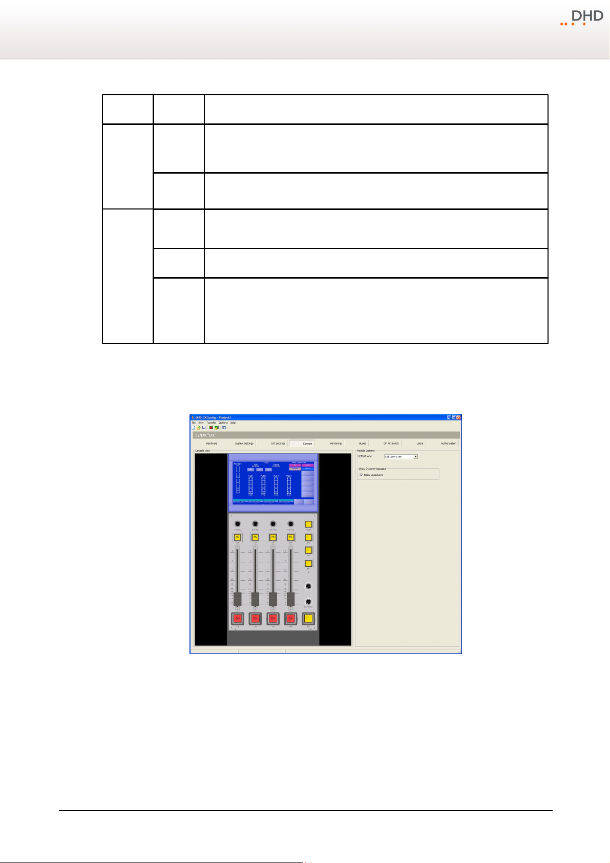
Configuration
area
option
description
IOModule-X.
<port>
General
Purpose
Inputs (GPI)
Type of
Signal
Shows the general signal type of the port.
Enter Label
Enter a distinctive name for the selected input.
IOModule-X.
<port>
General
Purpose
Inputs
(GPO)
Type of
Signal
Shows the general signal type of the port.
Enter Label
Enter a distinctive name for the selected input.
Select
Source
You can assign a logic sources to the selected GPO.
Click the
Source
button, the
Logic sources
window opens. Select a logic source, and
click
Assign
.
41
10.5 Console
On the
Console
page you can configure keys, TFT views and the OLED display on the central module.
DXConfig Software - Console
To configure an element, select it in the
Console View
Specifications and design are subject to change without notice. The content of this document is for information only. The information presented in this document does not form part
of any quotation or contract, is believed to be accurate and reliable and may be changed without notice. No liability will be accepted by the publisher for any consequence of its use.
Publication thereof does neither convey nor imply any license under patent rights or other industrial or intellectual property rights.
area.
Console View
area. Its options are shown in the area to the right of the
Version 1.2.0 - 04.02.2013
Page 45
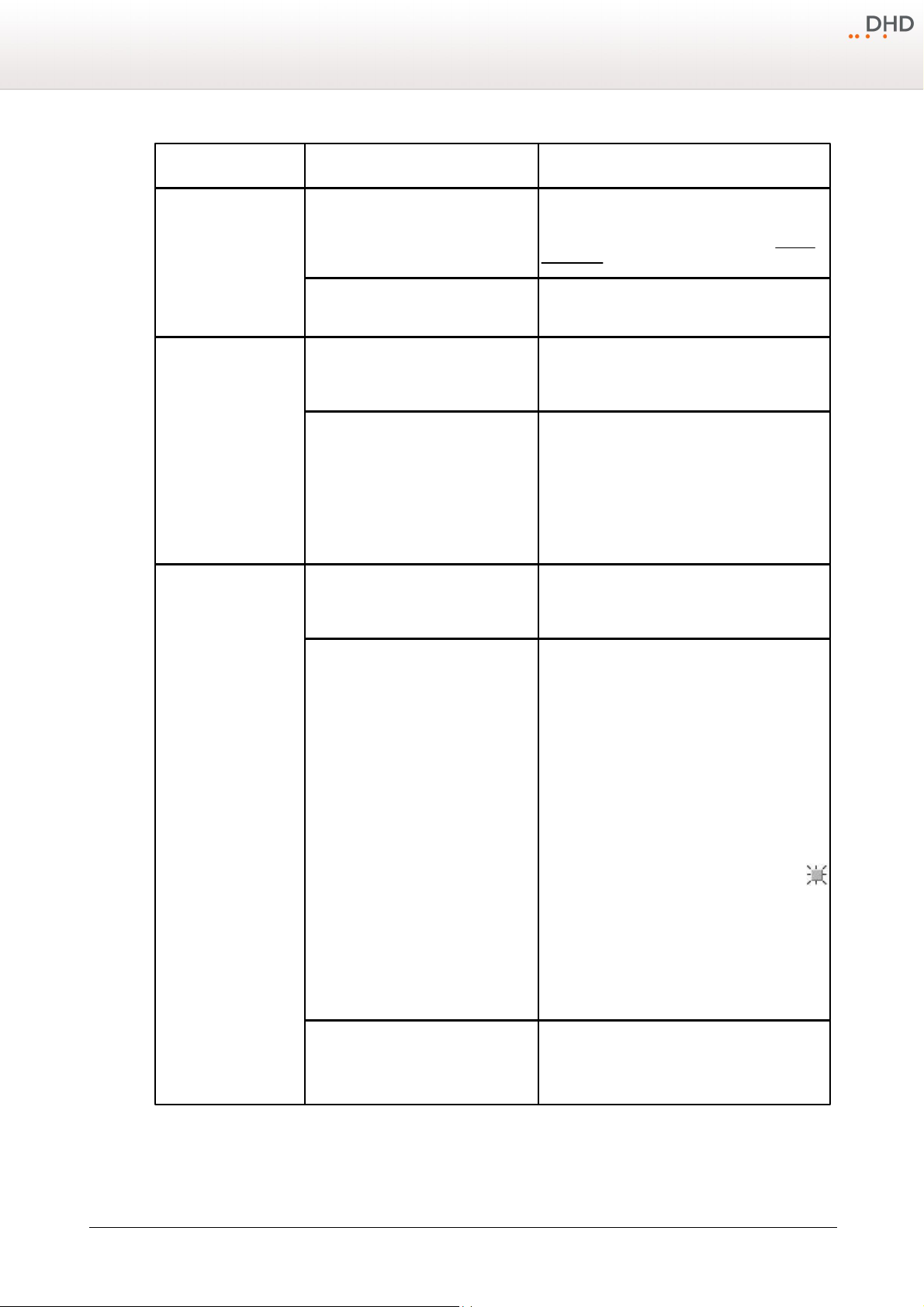
42
Element
option
description
TFT/Touch Display
Default View
In this list, all available default TFT views are
shown. Select a default view from the list. (For
differences between the default views see Default
views table)
Show System Messages
Select the check box in front of the system
message to enable it on the TFT/Touch Display.
key
Number
Shows the generated number of the selected key:
<name of fader module>.Key<key number on this
module>
Function
Shows the assigned key function.
To change the default key function of a key, follow
these steps:
1. Select a key on the console view.
2. In the
View
menu, select
Key Functions
.
The
Key Functions
window opens.
3. In the
Key Functions
window select a Key
Function from the list and click
Select
.
… key
Label
Enter a name for the key. This name will be shown
in the Console View and will be available for the
label print feature.
Colors
Depending on the selected key function, you can
define here, with which color the key shall light up
according to the lamp source.
On
is the color if the
function is enabled,
Off
if the function is in
inactive condition. For the last case, mostly the
Off
option is used, for example the key does not
light up. Depending on the selected key function,
you find also different names in the
Lamp Source
column, for example
Standby, Available
,
Busy, Owned, Layer A, Layer B
or the name
of the selected
lamp source
.
You can define the colors red and yellow. You can
define flashing colors for the keys. Select the
check box, in the
Colors
area.
To change the logic source for a color, select an
entry in the
Lamp Source
column and click
Source
. The
Logic Sources
window opens. In
the
Logic Sources
window, select a logic
source from the list and click
Assign
.
Toggle Mode
Momentary
- The function is enabled as long as
the key is pressed.
Toggle
- This key is stay put.
Timed Toggle
- This key is stay put (short press)
or spring return (long press).
Series 52 - 52/DX Compact Mixing Console Manual
© 2013 DHD Deubner Hoffmann Digital GmbH
Specifications and design are subject to change without notice. The content of this document is for information only. The information presented in this document does not form part
of any quotation or contract, is believed to be accurate and reliable and may be changed without notice. No liability will be accepted by the publisher for any consequence of its use.
Publication thereof does neither convey nor imply any license under patent rights or other industrial or intellectual property rights.
Page 46
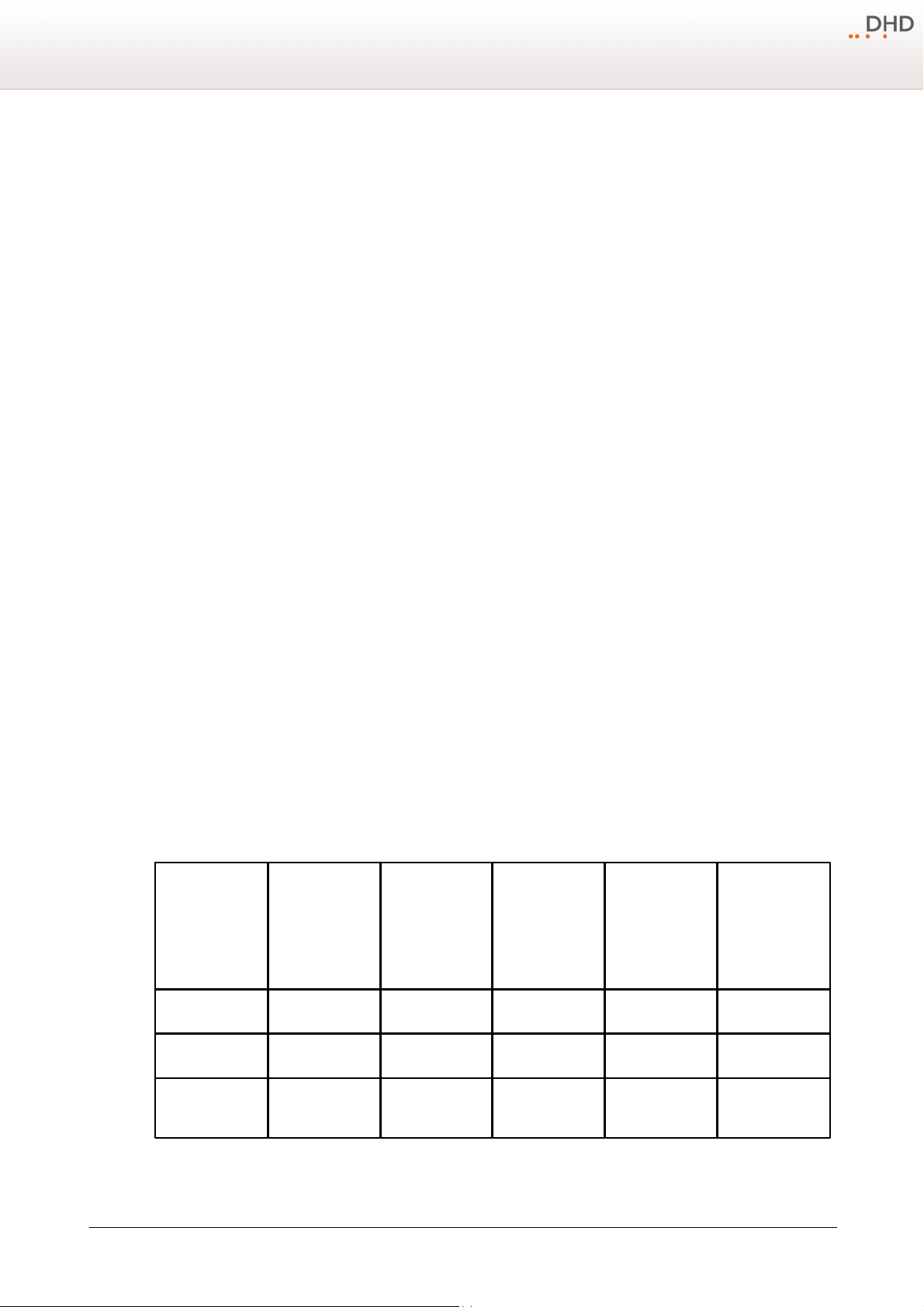
Monitoring key - Program:
view name
standard
elements (Std)
(PGM peak meter,
CUE peak meter, 4
state indicators,
navigation buttons,
access buttons for
faders)
clock (Clk)
three additional
peak meter for
PGM 2, Aux 1,
Aux 2 (3PM)
timer (Tmr)
sync status
indicators
Std+ClkXX
X
Std+Clk+3PMXXXX
Std+Clk+3PM
+Tmr
XXX
X
Configuration
43
Press the
Program
audio sources which is selected in the
this
bus, follow these steps:
Mon1
1. On the TFT Touch display tap on the
2. At the bottom of the TFT Touch display, tap on
3. In the
Selector Sources
key, to send the PGM 1 bus audio signal to the Mon1 bus. When the
Selector
Selector
view on the TFT is sent to the
button. The
Selector
Selector
.
Mon1
view is shown.
area, tap on the audio source that should be routed to the
Program
key is not active, the
bus. To set the audio source for
bus.
Mon1
General Purpose keys - GP1, GP2, GP3:
You can configure these keys as User Defined Key.
User defined:
· By right-clicking
(not assigned)
select any source from the
logic sources
in the
Lamp Source
column, you can either select the key itself as a source or
window.
· You can use the key as a logic source in many ways, for example for the On-Air Switch or routing to GPOs.
· You can change the sequence of the three rows in the Colors area. Drag a row in the
Lamp Source
column to its
new priority place.
· The LED with higher priority lights up if its lamp source is active; two colors can't light up at the same time!
· The LEDs of the keys can also be used to show a condition without having assigned a key function. This is useful for
signalisation via GPIs.
Key - Talk:
You can configure this key only as User Defined Key.
User defined:
· By right-clicking
(not assigned)
select any source from the
logic sources
in the
Lamp Source
column, you can either select the key itself as a source or
window.
· You can use the key as a logic source in many ways, for example for the On-Air Switch or Talkback.
· You can change the sequence of the three rows in the
Colors
area. Drag a row in the
Lamp Source
column to its
new priority place.
· The LED with higher priority lights up if its lamp source is active; two colors can't light up at the same time!
· The LEDs of the keys can also be used to show a condition without having assigned a key function. This is useful for
signalisation via GPIs.
Specifications and design are subject to change without notice. The content of this document is for information only. The information presented in this document does not form part
of any quotation or contract, is believed to be accurate and reliable and may be changed without notice. No liability will be accepted by the publisher for any consequence of its use.
Publication thereof does neither convey nor imply any license under patent rights or other industrial or intellectual property rights.
Default views:
In the following table, the differences between the default TFT views are shown.
Version 1.2.0 - 04.02.2013
Page 47
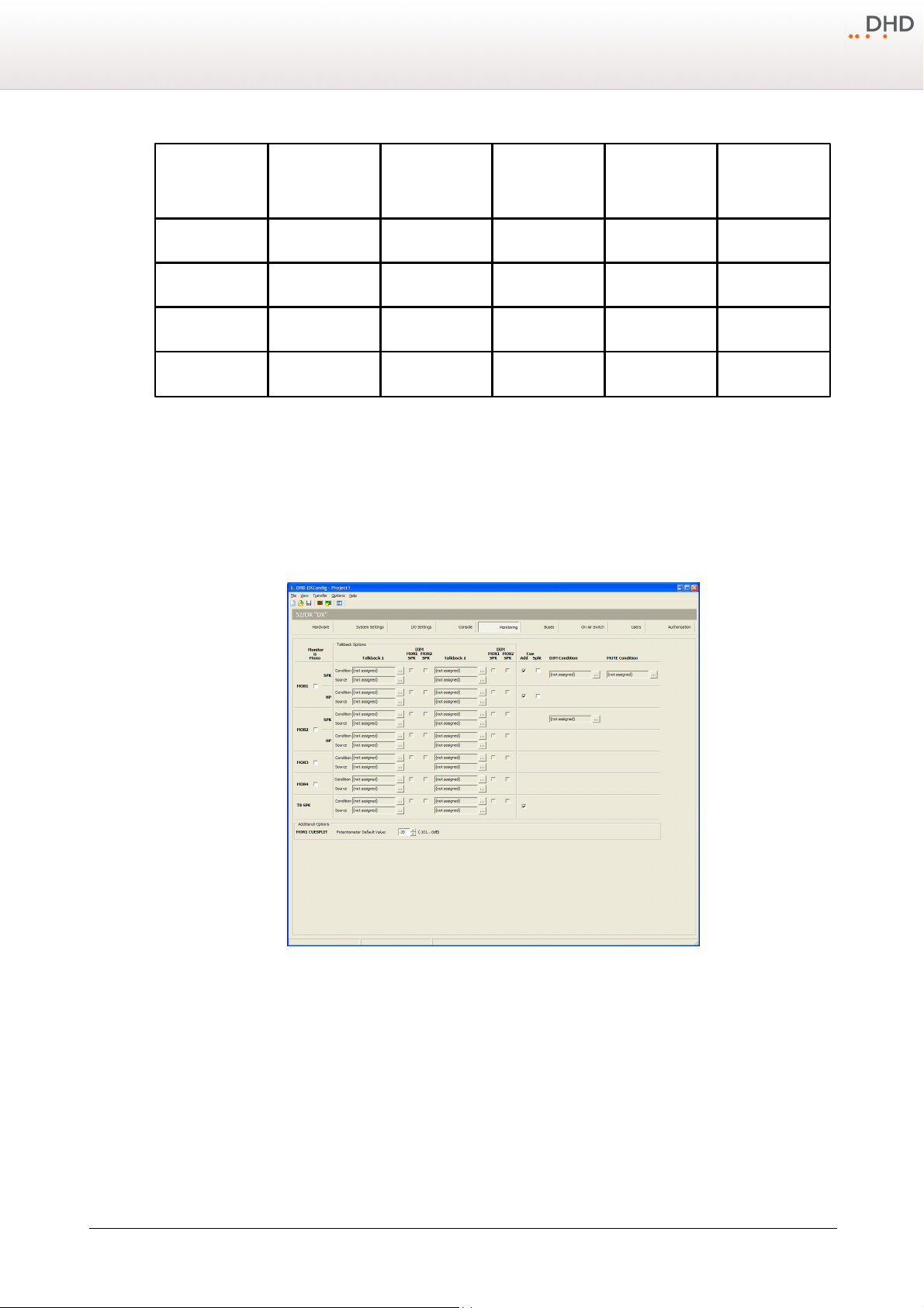
44
Std-CUE+Clk
X
(without CUE peak
meter)
X
X
Std+TmrXX
Std+3PM+Tmr
XXX
StdXStd+Clk+TmrXX
X
Series 52 - 52/DX Compact Mixing Console Manual
10.6 Monitoring
X…the element is available in this view
On the Monitoring page you can configure the monitoring features of the 52/DX and set up a simple talkback, for example
between the control room and the studio.
DXConfig Software - Monitoring
© 2013 DHD Deubner Hoffmann Digital GmbH
Specifications and design are subject to change without notice. The content of this document is for information only. The information presented in this document does not form part
of any quotation or contract, is believed to be accurate and reliable and may be changed without notice. No liability will be accepted by the publisher for any consequence of its use.
Publication thereof does neither convey nor imply any license under patent rights or other industrial or intellectual property rights.
Each row on this page is an output function and available as an audio signal source for any output from the
Sources
window.
Audio
Page 48
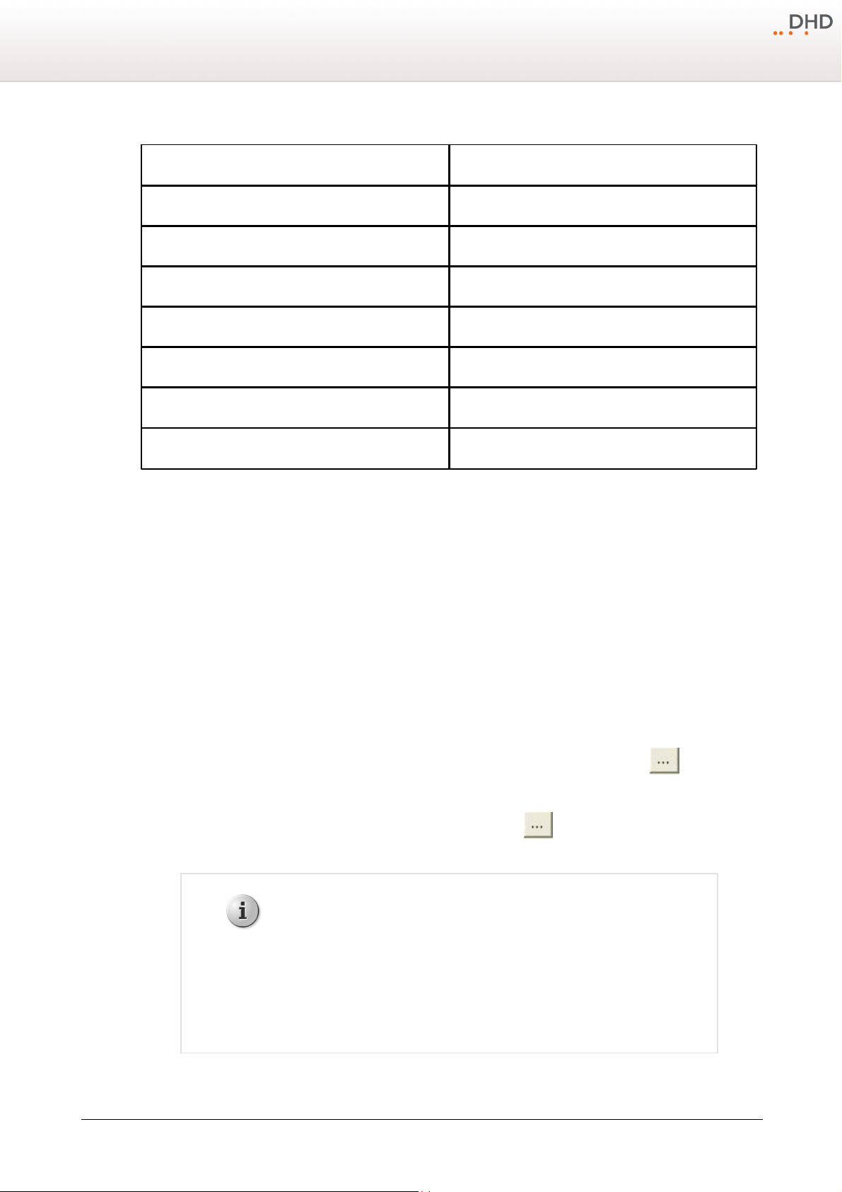
These output functions belong to the monitoring signals on this page:
name on Monitoring page
output function
MON1 SPK
MON1 SPK Vol L
MON1 SPK Vol R
MON1 HP
MON1 HP Vol L
MON1 HP Vol R
MON2 SPK
MON2 SPK Vol L
MON2 SPK Vol R
MON2 HP
MON2 HP Vol L
MON2 HP Vol R
MON3
MON3 Vol L
MON3 Vol R
MON4
MON4 Vol L
MON4 Vol R
TB SPK
TB SPK
Note
To select the main input source for the monitoring busses, you have to assign a
audio signal. To do this, follow these steps:
1. On the main page, on the TFT/Touch Display of the 52/DX, tap on
Selector
.
2. On the bottom of the TFT/Touch Display, select the monitoring bus.
3. In the
Selector Sources
area, on the TFT/Touch Display, tap on the
signal source to assign it to the monitoring bus.
Configuration
45
For the monitoring signals 1 to 4, you can select the
The
TB SPK
signal is always mono.
Monitor is Mono
check box, if the monitoring signal is mono.
For the monitoring signal 1 (Speaker and Headphone), you can decide what happens when a CUE signal (PFL) is available.
If nothing is selected, no PFL signal will be available on this monitoring signal. Select the
CUE signal with the monitoring signal. Select the
Cue Split
check box to assign the CUE signal to the left channel and
Cue Add
check box to mix the
the monitoring signal to the right channel. You can also adjust the ratio between the PFL signal and the monitoring signal
with one of the encoders next to the central OLED display. To do this, follow these steps:
1. On the
2. In the
Key Functions
3. Drag the
4. In the
5. In the
Potentiometer
Encoder
Console
Potentiometer
tab, on the central module, select one of the keys 9 to 12, the
window, double-click on
function to the
list, select
CUESPLIT
Monitor Functions
Function
entry in the
.
Key Options
Key Functions
.
list, select one of the encoders - F1-upper encoder, F2-lower encoder.
window opens.
area.
If you press the configured key on the 52-1010 central module, you can use the encoder to change the attenuation of the
monitoring signal. Default value is set to -20 dB, this can be increased to off.In the
can change the
MON1 CUESPLIT Potentiometer Default Value
to values between -101 dB and 0 dB.
Additional Options
area, you
To dim the volume (-20 dB) of the monitoring signals 1 or 2, you can assign a logic source. Click the button, next to
the
DIM Condition
To mute the monitoring signals 1, you can assign a logic source. Click the button, next to the
box. The
Logic Sources
box. The
Logic Sources
window opens. Select a logic source from the list and click assign.
window opens. Select a logic source from the list and click assign.
MUTE Condition
Specifications and design are subject to change without notice. The content of this document is for information only. The information presented in this document does not form part
of any quotation or contract, is believed to be accurate and reliable and may be changed without notice. No liability will be accepted by the publisher for any consequence of its use.
Publication thereof does neither convey nor imply any license under patent rights or other industrial or intellectual property rights.
Version 1.2.0 - 04.02.2013
Page 49
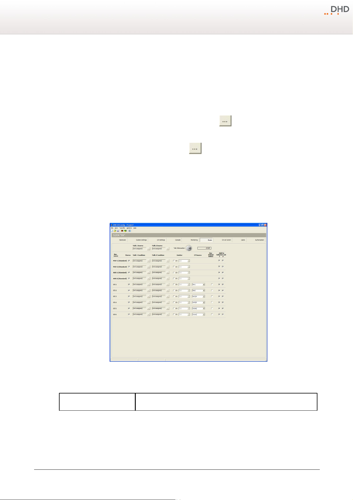
46
element
description
Series 52 - 52/DX Compact Mixing Console Manual
10.6.1 Talkback
On the
Monitoring
assign 2 talkback signals. These could be microphone inputs or other audio sources. You can switch on these talkback
signals by a logic source.
In the
Talkback 1/2
sources inserted in the
To assign an audio source, as talkback into a monitoring signal, click the button, next to the
Audio Sources
To assign an logic source as talkback condition, click the button, next to the
Sources
You can dim the monitor speaker signals, if a talk condition becomes true. To do this, select the corresponding
MON1/2 SPK
10.7 Buses
On the
Buses
page a talkback area with talkback specific settings is available. For each monitoring signal, you can
columns, in the
Condition
window opens. Select a audio source from the list and click assign.
window opens. Select a logic source from the list and click assign.
check box.
page you can configure the settings for all buses that are available in the 52/DX system.
Source
boxes.
boxes, you can insert an audio source which is activated by the logic
Condition
Source
box. The
box. The
Logic
DIM
DXConfig Software - Buses
In the following tables all options on this page are explained.
© 2013 DHD Deubner Hoffmann Digital GmbH
Specifications and design are subject to change without notice. The content of this document is for information only. The information presented in this document does not form part
of any quotation or contract, is believed to be accurate and reliable and may be changed without notice. No liability will be accepted by the publisher for any consequence of its use.
Publication thereof does neither convey nor imply any license under patent rights or other industrial or intellectual property rights.
Page 50
Configuration
Talk 1 Source
Click the button, next to the
Talk 1 Source
box. The
Audio Sources
window opens. Select a audio source from the list and click assign.
When the
Talk 1 Condition
logic becomes true, the
Talk 1 Source
is
active on the corresponding bus.
Talk 2 Source
Click the button, next to the
Talk 2 Source
box. The
Audio Sources
window opens. Select a audio source from the list and click assign.
When the
Talk 2 Condition
logic becomes true, the
Talk 2 Source
is
active on the corresponding bus.
Talk Attenuation
When a Talk Source is active, the busses can be attenuated between
0 dB
and
Off
in steps of 1 dB. Use the
Talk Attenuation
selector to change the
attenuation value.
column
description
Bus name
Here you can find the name of the bus for which you configure the following settings.
Stereo
Select this check box, if the bus is stereo. Clear the check box to configure the bus as
mono.
Talk 1 Condition
Click the button, next to the
Talk 1 Condition
box. The
Logic
Sources
window opens. Select a logic source from the list and click assign.
When this logic source becomes true, the
Talk 1 Source
is active on the
corresponding bus.
Talk 2 Condition
Click the button, next to the
Talk 2 Condition
box. The
Logic
Sources
window opens. Select a logic source from the list and click assign.
When this logic source becomes true, the
Talk 2 Source
is active on the
corresponding bus.
Limiter
Select the
On
check box to activate the limiter for this bus.
Select a threshold value from the drop-down menu (-30 dB to 20 dB).
CF Source
Select from the drop down menu an audio source for your clean feed signal
Use Output select
Select this check box to enable source selection for the alternative clean feed signal.
Add to Selector List 1
Select this check box to add a bus to source list 1. This bus will be available for
monitoring in the
Selector
list, which is available in the
Selector
view of the
TFT/Touch Display.
47
Specifications and design are subject to change without notice. The content of this document is for information only. The information presented in this document does not form part
of any quotation or contract, is believed to be accurate and reliable and may be changed without notice. No liability will be accepted by the publisher for any consequence of its use.
Publication thereof does neither convey nor imply any license under patent rights or other industrial or intellectual property rights.
Version 1.2.0 - 04.02.2013
Page 51
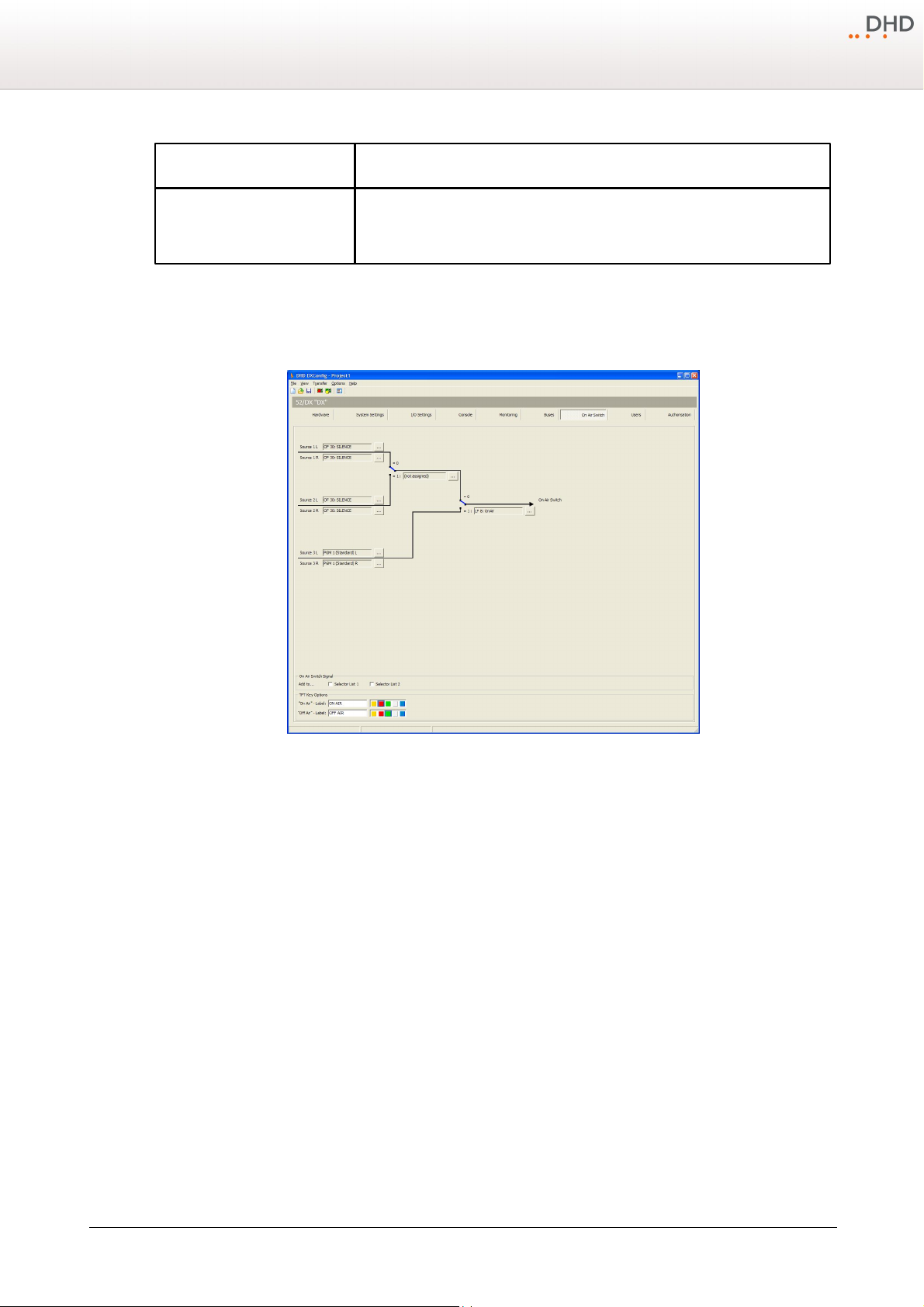
48
column
description
Add to Selector List 2
Select this check box to add a bus to source list 2. This bus will be available for
monitoring in the
Monitor 2
list, which is available in the
Selector
view of the
TFT/Touch Display.
Series 52 - 52/DX Compact Mixing Console Manual
10.8 On-Air Switch
The
On-Air Switch
You can select three stereo audio sources, which can be switched by two logic sources.
page gives you the possibility to change sources for an output controlled by logic sources.
DXConfig Software - On Air Switch
On the left-hand side you can see the audio sources of the On-Air switch. The black lines symbolise audio signal paths.
There are two blue-coloured signal switches, each with an associated logic sources (see figure On-Air Switch
configuration).
© 2013 DHD Deubner Hoffmann Digital GmbH
Specifications and design are subject to change without notice. The content of this document is for information only. The information presented in this document does not form part
of any quotation or contract, is believed to be accurate and reliable and may be changed without notice. No liability will be accepted by the publisher for any consequence of its use.
Publication thereof does neither convey nor imply any license under patent rights or other industrial or intellectual property rights.
Page 52
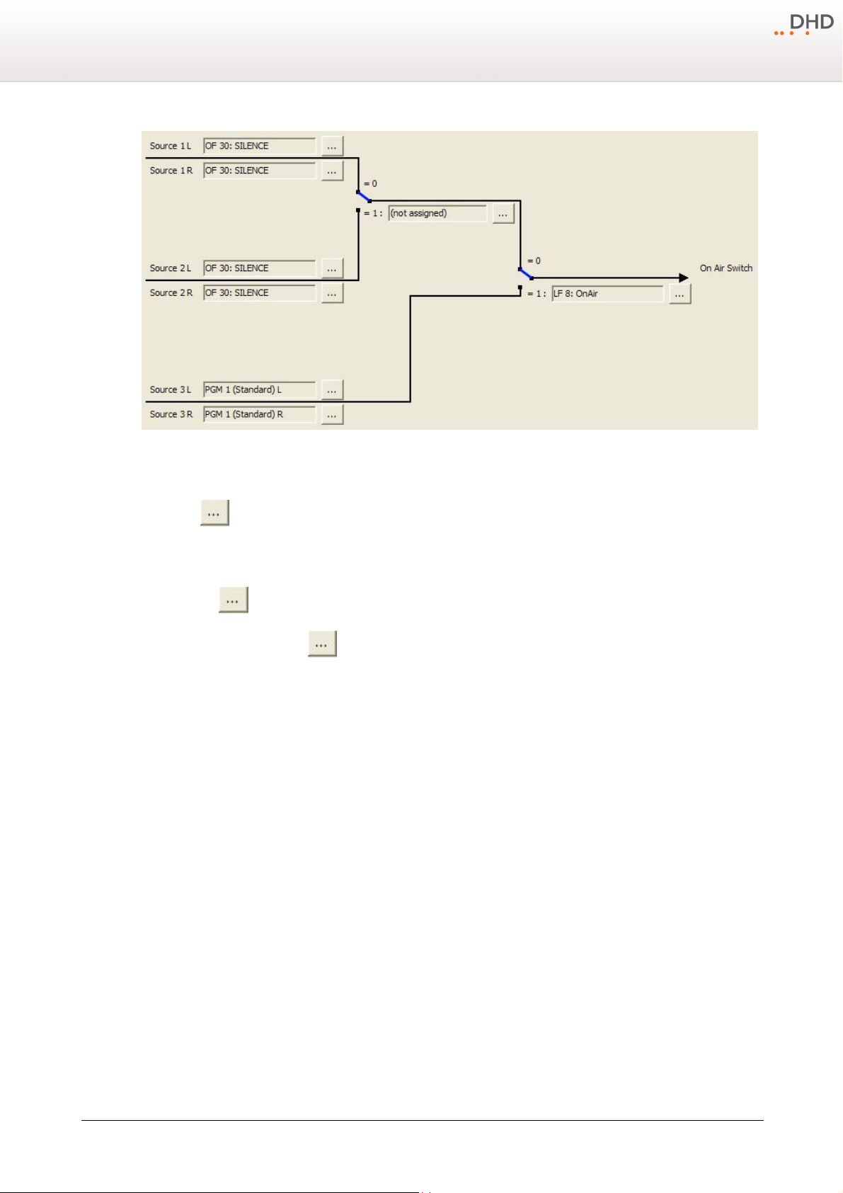
On-Air Switch configuration
Configuration
49
To configure the On-Air switch, follow these steps:
1. Click the -button next to the
2. In the
Audio Sources
or drag it to the
Source
3. Repeat steps 1 and 2 for the
Source 1L
window, select a source and click
box. The source is now assigned to the On-Air switch.
Sources 1R, 2L, 2R, 3L
4. The main switch on the right-hand side is assigned by default to the
source, click and select another logic source from the
5. The switch between
Source 2
will be used. Click and select another logic source from the
Source 1
and
Source 2
box, the
Audio Sources
Assign
and
3R
Logic Sources
window opens.
. Alternatively you can double-click on the source
.
OnAir
Logic Function. To change the logic
window.
has no default logic source and you have to select a logic source if
Logic Sources
window.
The main switch with its default logic source OnAir is already preconfigured in the 52/DX-System. To switch between
Source 3
and
Source 1
1. On the TFT/Touch Display, on the main page, tap on
2. Tap on the
3. Tap on the
In the
Selector List 2
Unlock
ON AIR
On Air Switch Signal
. You can find these lists on the
The Label and color for the corresponding TFT buttons can be changed in the
(or
Source 2
) follow these steps:
add. Settings
.
button, the button turns orange. Now it is possible to change the
button. The
ON AIR
button turns red.
Source 3
is now selected.
area, you can assign the On Air Switch Signal to the
Selector
view of the TFT/Touch Display.
TFT Keyoptions
Signal Switch
Selector List 1
area.
state.
and
Version 1.2.0 - 04.02.2013
Specifications and design are subject to change without notice. The content of this document is for information only. The information presented in this document does not form part
of any quotation or contract, is believed to be accurate and reliable and may be changed without notice. No liability will be accepted by the publisher for any consequence of its use.
Publication thereof does neither convey nor imply any license under patent rights or other industrial or intellectual property rights.
Page 53
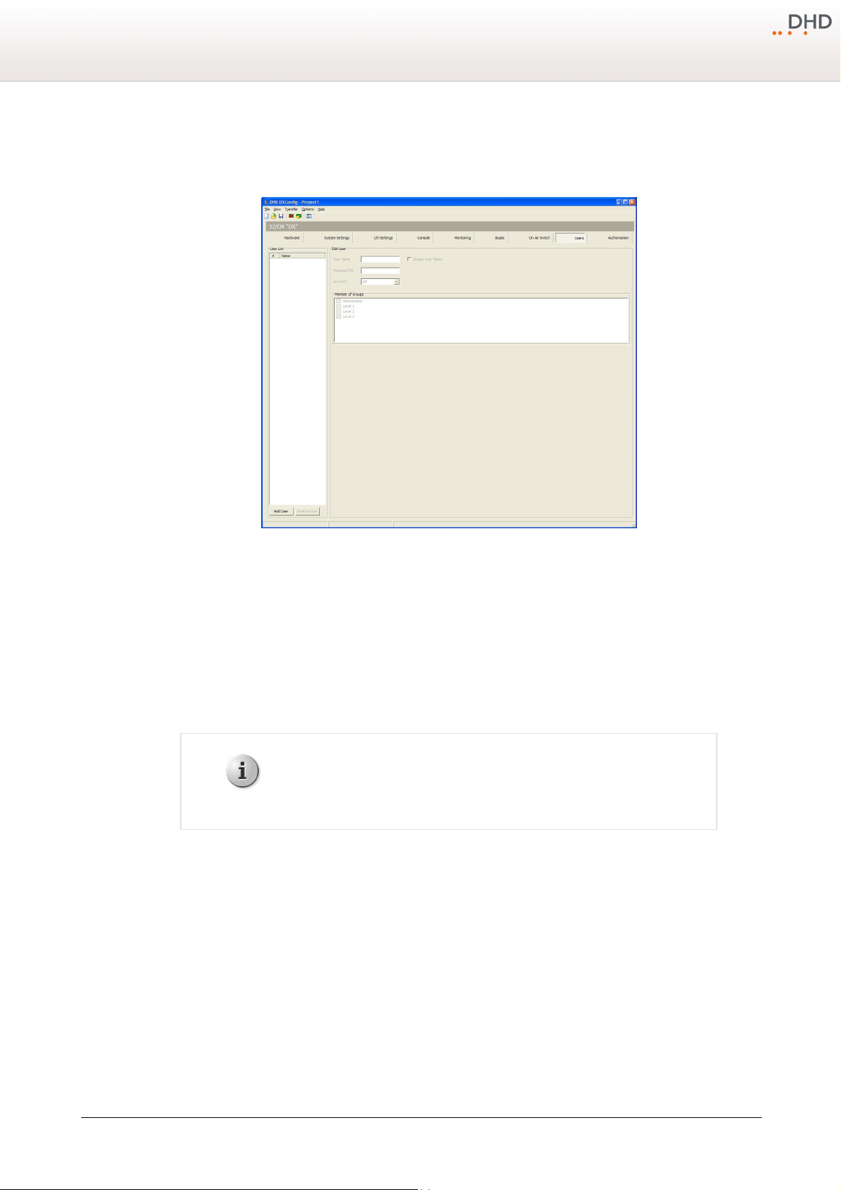
50
Note
The
Display User Name
check box has no function for 52/DX devices.
Series 52 - 52/DX Compact Mixing Console Manual
10.9 Users
On the
Users
You can create users with different access rights by assigning them to the preconfigured user groups. To do this, follow
these steps:
page you can you can create users with different access rights.
DXConfig Software - Users
1. In the
2. In the
3. In the
4. In the
You can log out the users automatically after a defined duration. After this duration the user has to log in again. Choose
this duration from the
to disable this feature.
User List
Edit User
Personal PIN
Member of Groups
area, click
area, in the User Name box, type a distinctive user name, for example "technician".
Autolock
Add User
box, enter a four-digit PIN code, which identifies the user at the log in process on the console.
area, select one or more user groups to assign the selected user to these groups.
drop-down menu. You can select 2, 5,
to create a new user.
10, 15, 20 or 30
minutes or select
Off
© 2013 DHD Deubner Hoffmann Digital GmbH
Specifications and design are subject to change without notice. The content of this document is for information only. The information presented in this document does not form part
of any quotation or contract, is believed to be accurate and reliable and may be changed without notice. No liability will be accepted by the publisher for any consequence of its use.
Publication thereof does neither convey nor imply any license under patent rights or other industrial or intellectual property rights.
Page 54
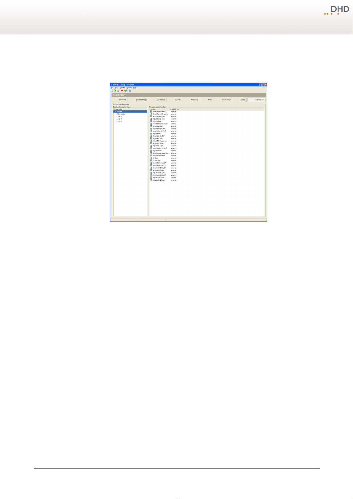
10.10 Authorisation
Configuration
51
On the
Authorisation
To assign access rights to authorisation groups, follow these steps:
page you can assign access rights for different preconfigured user groups.
DXConfig Software - Authorisation
1. In the
2. In the
In the
Group Name
Function
Available for
list, select a authorisation group.
column, select the check boxes in front of the functions, to enable the access for this group.
column, you can see for every function, which authorisation groups have access this function.
Version 1.2.0 - 04.02.2013
Specifications and design are subject to change without notice. The content of this document is for information only. The information presented in this document does not form part
of any quotation or contract, is believed to be accurate and reliable and may be changed without notice. No liability will be accepted by the publisher for any consequence of its use.
Publication thereof does neither convey nor imply any license under patent rights or other industrial or intellectual property rights.
Page 55
52 Series 52
Index
3
B
Breakout cables 9, 17
buses 46
3PM 41
4
44.1 kHz / 48 kHz 35
5
52-1330 9
52-7111 11, 17
52-7222 18
52-7223 18
52-7230 10, 11, 18
A
About 33
About this Book 2
Access button 16
access rights 50
ACI 18, 37
Add 44
analogue I/Os 11
APC 12
APC ports 20
assignment of the control modules 20
Audio Sources 27
Authorisation 51
Autolock 50
Aux 16
C
cables 20
cabling examples 20
CF Source 46
Clk 41
clock 35, 41
Colors 41
coloured encoders 16
Common settings 34
condition 44
configuration software 7
Console 41
Console Preview 34
Control modules 12
CUE 16, 41, 44
Cue Add 44
Cue Split 44
D
Device name 34
DeviceLink 20
digital inputs 11
Digital Out Mode 37
digital outputs 11
digital signal processing 8
DIM 44
DIM MON1/2 SPK 46
display 41
Dithering 37
download 32
DSP 8
DSub type 17
D-sub type 17, 18
© 2013 DHD Deubner Hoffmann Digital GmbH
Page 56
53Index
Dynamic 16
E
Encoder 16
EQ 16
Exit 25
Extern 41
F
fader 16
Fader Program Key Mode 35
features 7
File Menu 24
film labels 12
functional range 7
G
gain 16
GP 41
GP keys 16
GPI 17, 18, 37
GPO 17, 18, 37
H
Hardware page 34
headphone outputs 9, 10
Headroom 37
Help Menu 33
History 25
Input 16
internal clock 35
K
Key Features 7
key function 41
Key Functions 26
key labels 12
keys 12
L
labels 12
Limiter 46
line inputs 9, 11
line outputs 11
Load from Device 32
Load to Device 31
Logic Monitor 28
Logic Sources 26
M
MADI 34
Maintenance Window 26
microphone inputs 9, 10
mon 44
monitor selector 16
monitoring 44
mono 44
multichannel audio connection 12
Multi-I/O Box 9
MUTE 44
Mute Logic 37
I
I/O boxes 20
I/O connections 34
I/O Settings 37
N
New Device 24
© 2013 DHD Deubner Hoffmann Digital GmbH
Page 57
54 Series 52
O
Off Air 35
Off-Air 48
OLED displays 41
On Air Switch Signal 48
ON key 16
On-Air 48
Open Device 24
Options Menu 32
output 48
output function 44
Selector 41
Selector List 46, 48
Show System Messages 41
source 44
Split 44
state indicator 41
Std 41
stereo 37, 44
switch 48
switchable Audio 48
SX Config 7
SX Fader Modules 34
Synchronisation 35
System Settings page 35
P
pages 41
peakmeter 41
Peakmeter Option 35
PFL 16
Pin assignment 17, 18
Pin assignment 52-7111 17
Pin assignment 52-7222 18
Pin assignment 52-7223 18
potentiometer 16
Program 16, 41
Program Menus 24
R
real-time operation 7
Red Bar Over 35
S
T
Talk 41
Talk 1 Condition 46
talk condition 46
talk key 16
Talkback 44, 46
TB SPK 44
Terms of Use 1
TFT Keyoptions 48
TFT pages 41
TFT State Indicators 35
TFT Touch display 16
TFT view 41
TFT/Touch Display 41
TFT/Touch displays 20
timer 41
tmr 41
Toolbox5 7
touch 16
Transfer Menu 29
sample rate 35
Save Device 24
Save Device as 24
Scale Color 35
Scale Type 35
© 2013 DHD Deubner Hoffmann Digital GmbH
U
upload 31
USB audio 21
user group 51
Page 58
users 50
V
view 41
View Menu 26
W
Watches - Logic Monitor 28
Windows 7 21
Windows Vista 21
X
55Index
XS Core 8, 34
XS Multi-I/O Box 34
Z
Zero Offset 35
© 2013 DHD Deubner Hoffmann Digital GmbH
 Loading...