

Page 1
Series 52
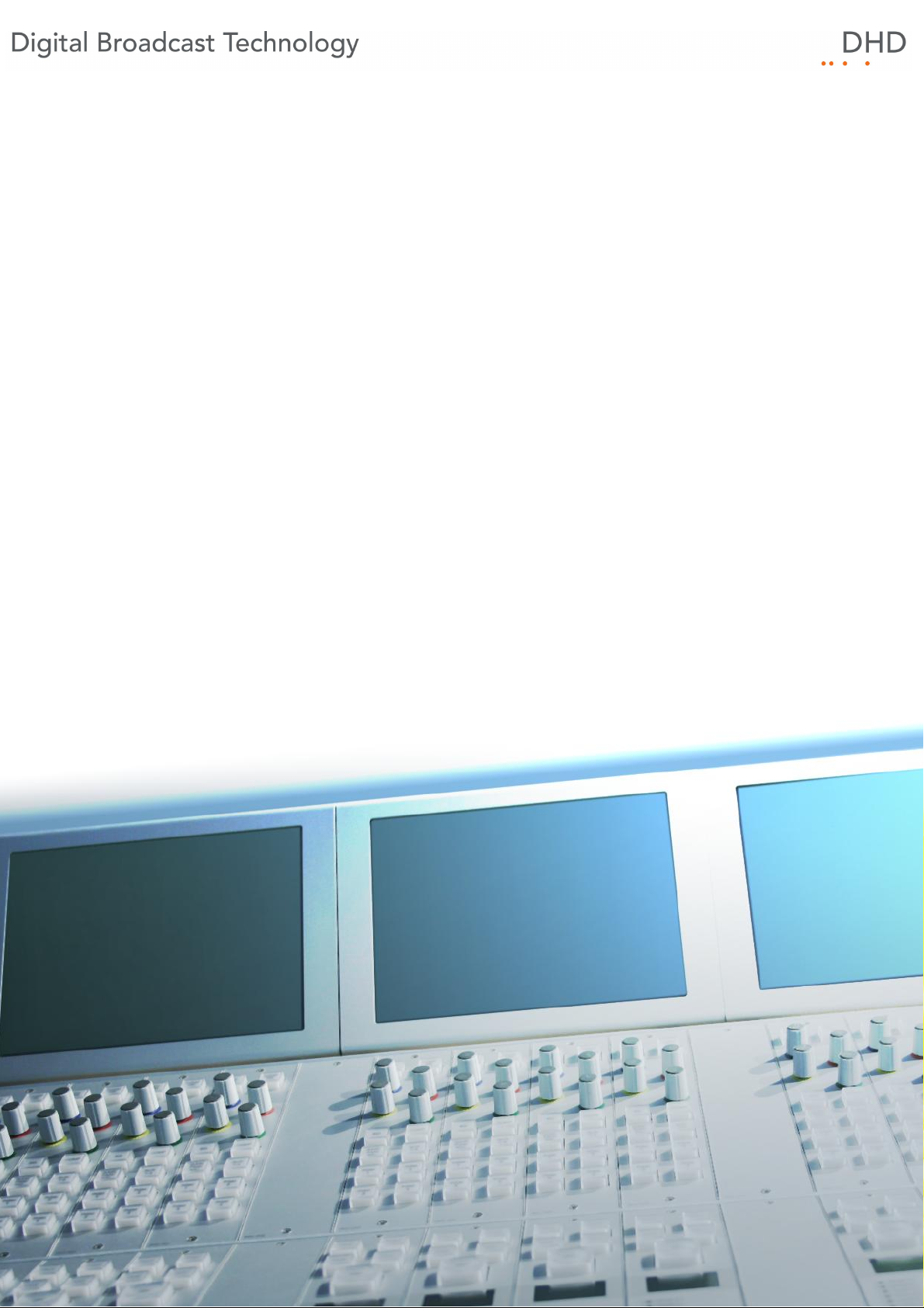
52/MX Mixing Console
Installation Guide
© 2010 DHD Deubner Hoffmann Digital GmbH
Version: 1.10.0
Page 2
Table of Contents
Table of Contents
1 Terms of Use - Legal Disclaimer
About this Book
2
3 What is new in this version of the manual?
4 Environmental Specifications
5 Assembling and Wiring the Hardware
1 Wiring the Console
System Wiring
2
3 Calculating the Power Consumption
................................................................................................................................... 6
................................................................................................................................... 8
......................................................................................................................................................... 10Meaning of the Controller Module LEDs
................................................................................................................................... 11
......................................................................................................................................................... 14Power Consumption Example 1
......................................................................................................................................................... 15Power Consumption Example 2
......................................................................................................................................................... 16Power Consumption Example 3
Index
1
2
4
6
6
© 2010 DHD Deubner Hoffmann Digital GmbH
Page 3
1
Series 52 - 52/MX Mixing Console Installation Guide
1 Terms of Use - Legal Disclaimer
Series 52
52/MX Mixing Console Installation Guide
© 2010 DHD Deubner Hoffmann Digital GmbH
This manual is copyright of DHD. It might be distributed and copied as long as it is copied completely as a whole and this
copyright notice is included.
No part of this document may be copied or distributed without prior written permission of DHD Deubner Hoffmann Digital
GmbH.
Windows is a registered trademark of Microsoft Corp., Redmond, Wash., USA. All other trademarks are the property of
their respective owners.
Specifications and design are subject to change without notice.
The content of this document is for information only. The information presented in this document does not
form part of any quotation or contract, is believed to be accurate and reliable and may be changed without
notice. No liability will be accepted by the publisher for any consequence of its use. Publication thereof
does neither convey nor imply any license under patent rights or other industrial or intellectual property
rights.
Version 1.10.0, 17.03.2010
© 2010 DHD Deubner Hoffmann Digital GmbH
Specifications and design are subject to change without notice. The content of this document is for information only. The information presented in this document does not form part
of any quotation or contract, is believed to be accurate and reliable and may be changed without notice. No liability will be accepted by the publisher for any consequence of its use.
Publication thereof does neither convey nor imply any license under patent rights or other industrial or intellectual property rights.
Page 4
2 About this Book
Note
This manual mainly refers to the physical installation of an 52/MX Mixing
Console. Please find more information on this device in the 52/MX manual.
Please see the RM4200D manual to get more information on the RM4200D DSP
Frame.
The configuration of the 52/MX Mixing Console and the RM4200D DSP Frame is
described in the Toolbox5 configuration software manual.
This installation guide will provide you a short introduction how to install an 52/MX Mixing Console.
The content of this manual is subject to change without notice. DHD recommends to visit the DHD website once in a while
to check if there is a newer version of this document available.
About this Book
2
How to Use this Book
The Navigation Tree
You can find the navigation tree on the left-hand-side of the PDF document. Via the entries of this tree you can directly
reach the several chapters and sections of this document. Click onto the text or the symbol of an entry to display its
content.
If a chapter includes further sections, you will find a plus-symbol in front of the entry in the navigation tree. Either you can
click onto this plus-sign or you double click the text or the symbol of the entry to make the sub-branches of the further
sections visible.
Search
You can find an alphabetical ordered list of keywords at the end of the document. Please see the page numbers in this
index to find the respective keywords in the document.
Moreover, you can use the search function of your PDF reader to seek for any words.
Links
Links are underlined to separate them from the rest of the text. These links can be a connection to other chapters or
sections in the same document or to an URL (internet address).
· Same document: The hand symbol appears if you move the mouse over the link.
· URL: The hand symbol with an additional w appears if you move the mouse over the link.
Please notice, that you need an active internet connection to be able to execute a link to an URL.
Specifications and design are subject to change without notice. The content of this document is for information only. The information presented in this document does not form part
of any quotation or contract, is believed to be accurate and reliable and may be changed without notice. No liability will be accepted by the publisher for any consequence of its use.
Publication thereof does neither convey nor imply any license under patent rights or other industrial or intellectual property rights.
Version 1.10.0 - 17.03.2010
Page 5
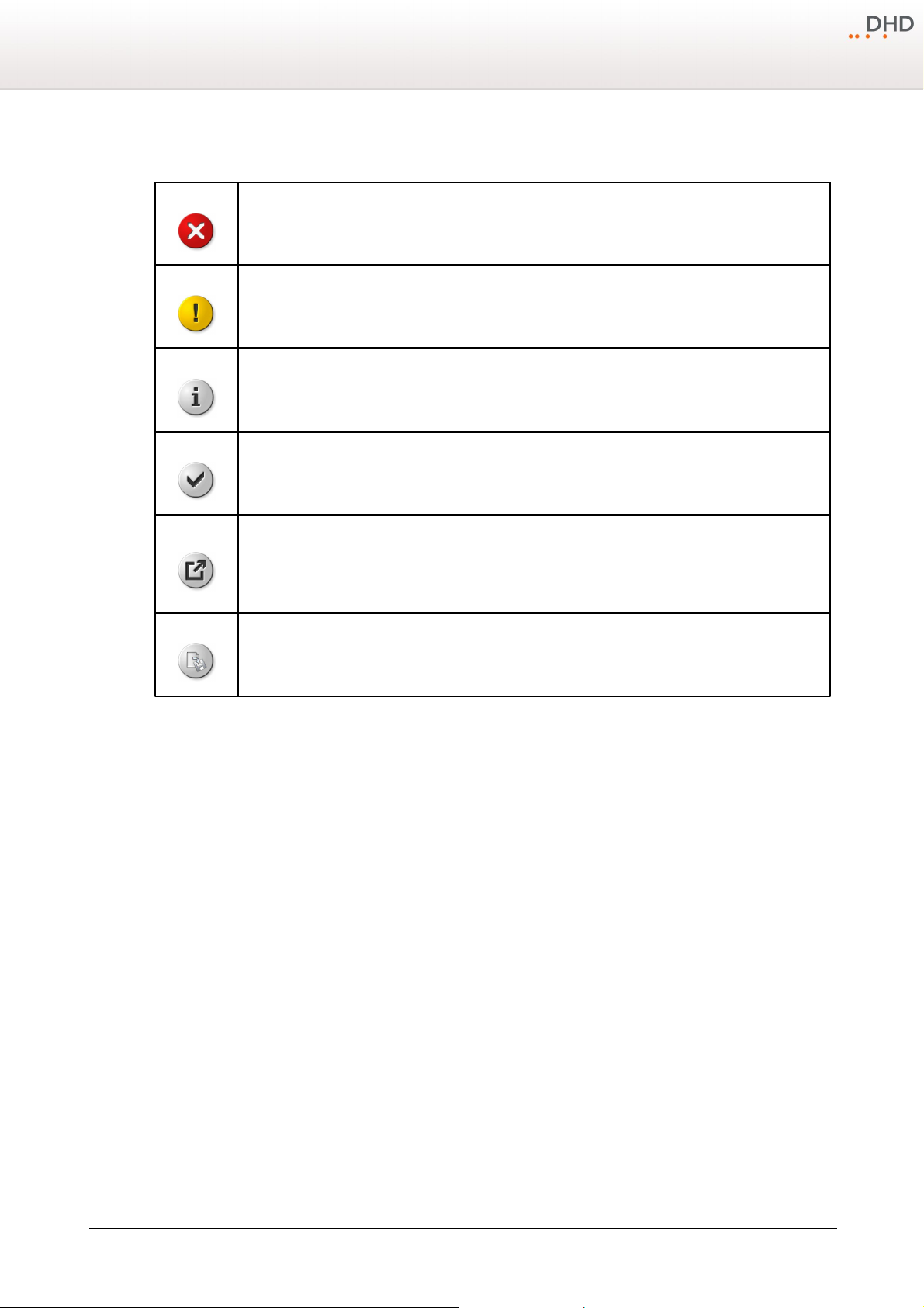
3
Warning
The demands and advices in this fields should be followed unconditional, because otherwise hardware
and software products, data bases, as well as persons may suffer a loss.
Important
The demands and advices in this fields should be followed, because these contents are necessary for the
proper operation of the DHD systems.
Note
Recommendations and further information are marked as notes. Sometimes you will also find off-topic
content in this field, which is related to the actual topic.
Tip
Tips are helpful advices, which should make work with DHD systems easier.
Weblink
In this fields you can find links to websites, which include for example an other manual or the possibility to
download a driver for the respective DHD system.
Please notice, that you need an active internet connection to be able to execute a link to an URL.
Download
You can directly open and download a file if the respective link is marked as download link (file link).
Series 52 - 52/MX Mixing Console Installation Guide
The Meaning of Advices in the Text
© 2010 DHD Deubner Hoffmann Digital GmbH
Specifications and design are subject to change without notice. The content of this document is for information only. The information presented in this document does not form part
of any quotation or contract, is believed to be accurate and reliable and may be changed without notice. No liability will be accepted by the publisher for any consequence of its use.
Publication thereof does neither convey nor imply any license under patent rights or other industrial or intellectual property rights.
Page 6
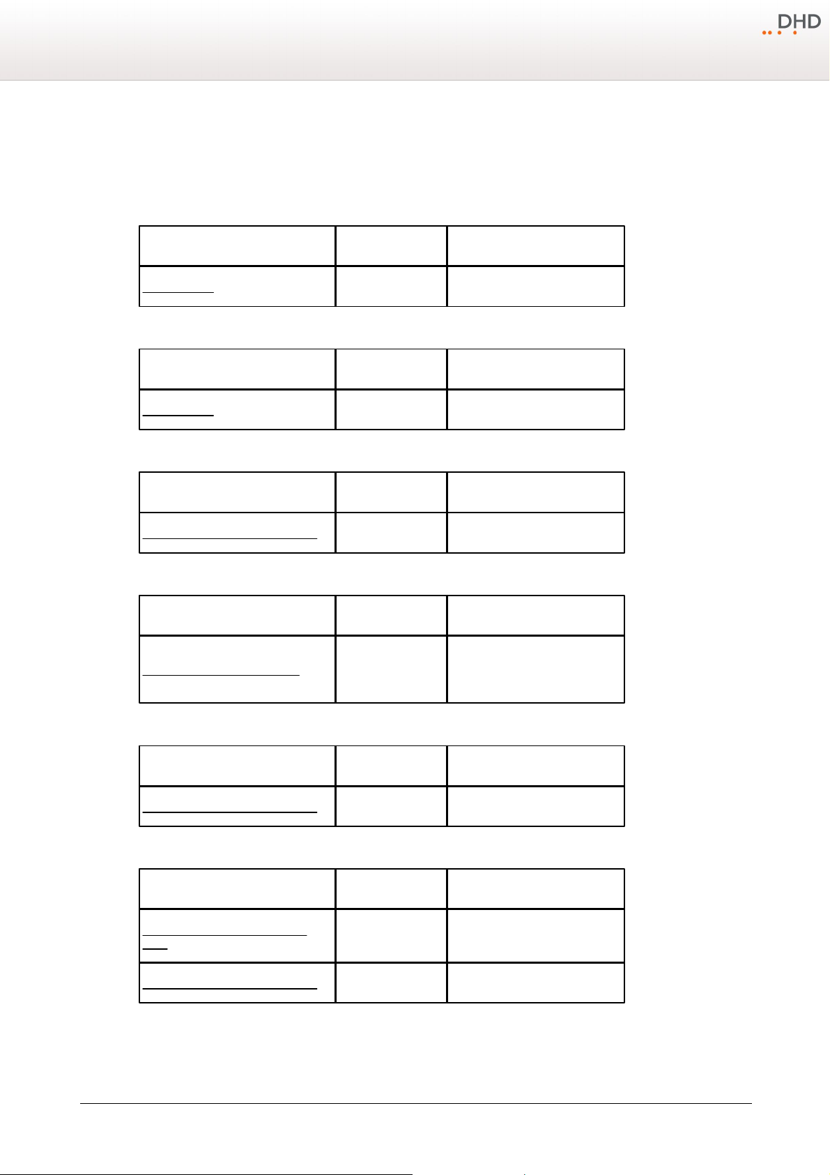
What is new in this version of the manual?
Chapter / Section
State
Note
System Wiring
changed
Information added.
Chapter / Section
State
Note
System Wiring
changed
Information added.
Chapter / Section
State
Note
Calculating the Power Consumption
changed
Information added.
Chapter / Section
State
Note
Terms of Use - Legal Disclaimer
changed
Formal adaptations. Legal
disclaimer added to the footer of
all topic pages.
Chapter / Section
State
Note
Calculating the Power Consumption
changed
Picture added.
Chapter / Section
State
Note
Meaning of the Controller Module
LEDs
added
Calculating the Power Consumption
changed
Information changed.
3 What is new in this version of the manual?
All sections that had been added, deleted or changed are listed below. Click on the entries to reach the respective sections
directly.
Current version (1.10.0):
Version 1.9.0:
Version 1.8.0:
4
Version 1.7.0:
Version 1.6.0:
Version 1.5.0:
Version 1.4.0:
Specifications and design are subject to change without notice. The content of this document is for information only. The information presented in this document does not form part
of any quotation or contract, is believed to be accurate and reliable and may be changed without notice. No liability will be accepted by the publisher for any consequence of its use.
Publication thereof does neither convey nor imply any license under patent rights or other industrial or intellectual property rights.
Version 1.10.0 - 17.03.2010
Page 7
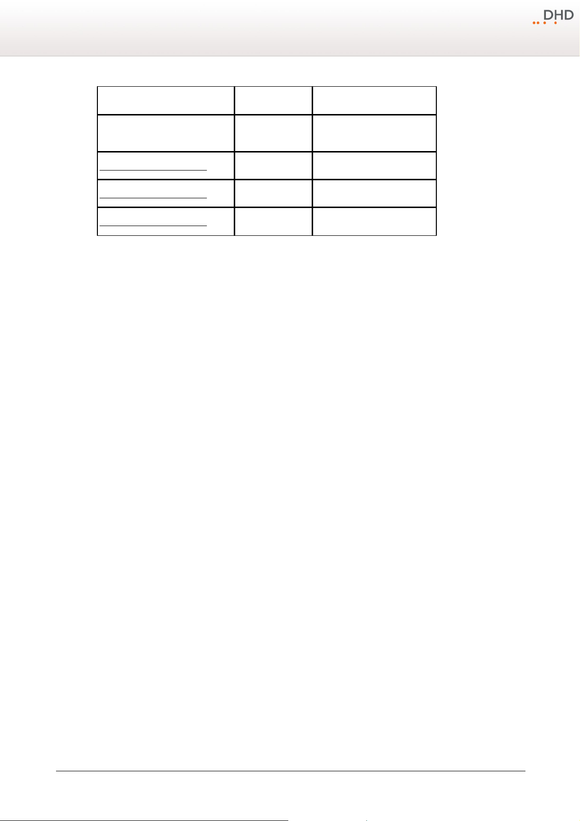
5
Chapter / Section
State
Note
What is new in this version of the
manual?
added
This section.
Power Consumption Example 1
added
Power Consumption Example 2
added
Power Consumption Example 3
added
Series 52 - 52/MX Mixing Console Installation Guide
Version 1.3.0 and before:
No changelog available.
© 2010 DHD Deubner Hoffmann Digital GmbH
Specifications and design are subject to change without notice. The content of this document is for information only. The information presented in this document does not form part
of any quotation or contract, is believed to be accurate and reliable and may be changed without notice. No liability will be accepted by the publisher for any consequence of its use.
Publication thereof does neither convey nor imply any license under patent rights or other industrial or intellectual property rights.
Page 8
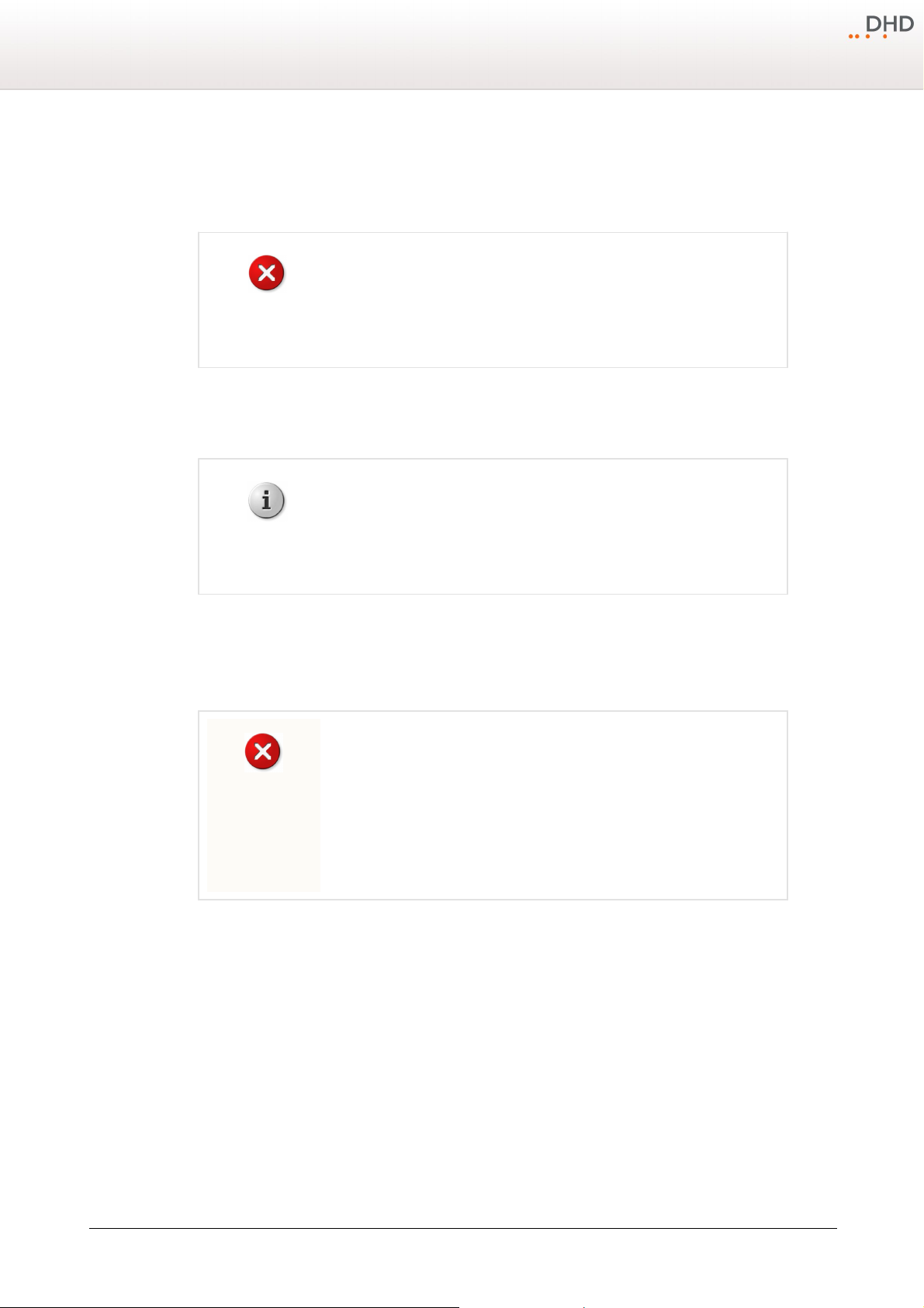
4 Environmental Specifications
Warning
Make sure the device has the operating temperature before switching it on. Also,
the relative humidity must not be exceeded. Above all, no humidity must
condense on or in the device!
operating temperature:
+5 ... +35° Celsius
relative humidity:
20 ... 85%, non condensing
Note
Please note the environmental specifications of the RM4200D DSP Frame, which
is connected to the 52/MX Mixing Console. Information on that can be found in
the RM4200D system reference guide.
Warning
Avoid damaging components by electrostatic discharge (ESD).
Before you touch or mount electronical components, make sure you do not carry
any electrostatic charges. Earth yourself using a grounded metal object (heater,
rack) to divert electrostatic charges immediately before you touch electronical
components.
In the following you can find some general advices concerning the environment of an 52/MX. If these values and
standards are not adhered, DHD can not assure the proper functionality of the device.
Environmental Specifications
6
5 Assembling and Wiring the Hardware
In the following you can find information on the mechanical assembling and wiring of an 52/MX Mixing Console and how to
integrate it into a mixing system.
5.1 Wiring the Console
At first you have to keep in mind that it is possible to arrange an 52/MX Mixing Console with a lot of different shapes and
sizes. Because of that it is not possible to explain the wiring process in detail for every mechanical assembly, but the basic
structure is always quite the same.
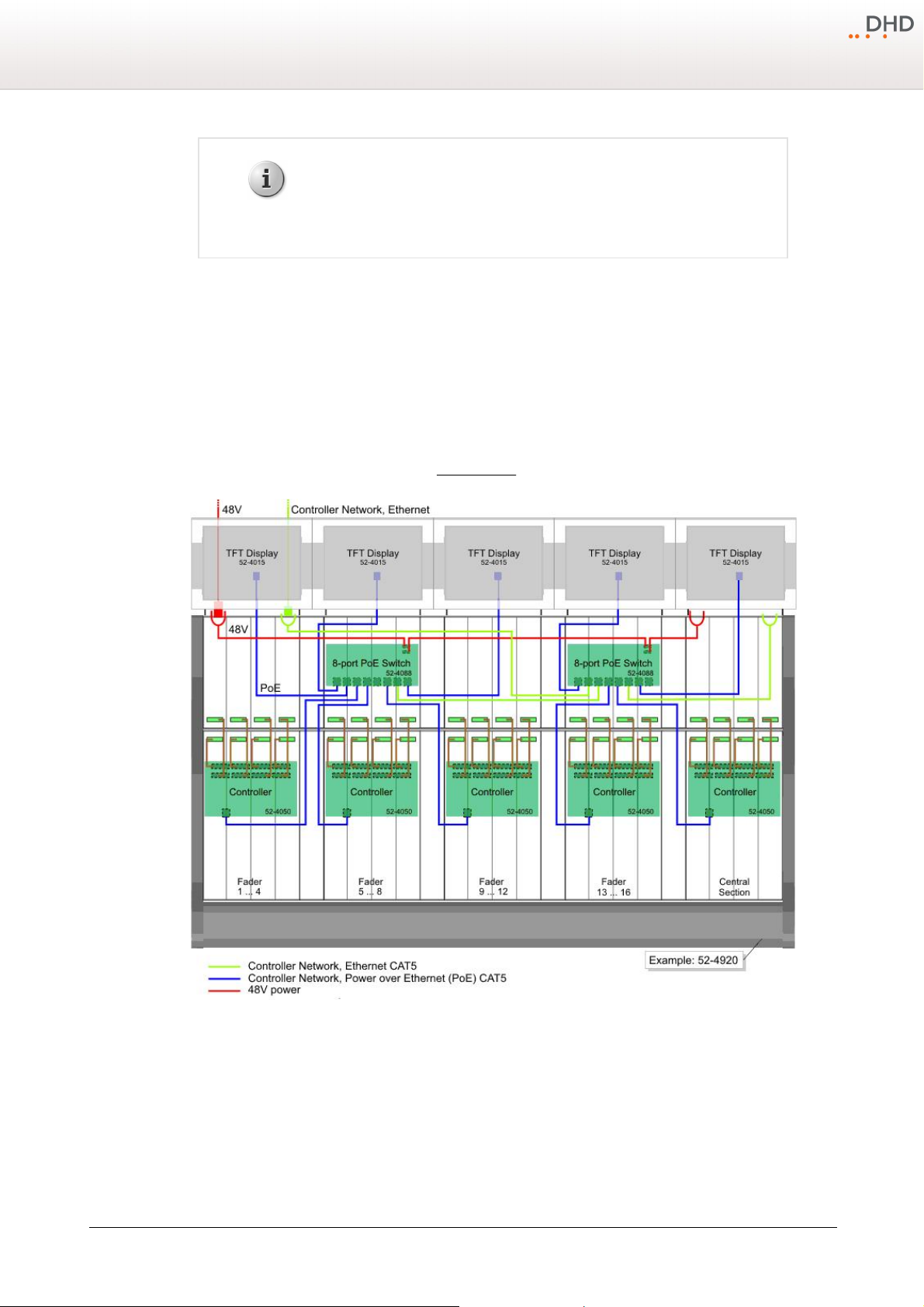
Here is the way how to wire the exemplary console in the picture below.
1. Normally, the 52-4050 Console Controller modules are already mounted in the console frame. If not so, you have to do
this first.
2. Mount the PoE switches in the console frame or put them into the shipped wall mount housings and install these
housings close to the console frame. Within this flow of work, connect the red and blue power supply flat connectors of
the PoE switches with each other and at least one of them with an outward speakon jack. (See the red cables in the
picture below.)
Specifications and design are subject to change without notice. The content of this document is for information only. The information presented in this document does not form part
of any quotation or contract, is believed to be accurate and reliable and may be changed without notice. No liability will be accepted by the publisher for any consequence of its use.
Publication thereof does neither convey nor imply any license under patent rights or other industrial or intellectual property rights.
Version 1.10.0 - 17.03.2010
Page 9
7
Note
To power the modules of the mixing console, you need at least one PoE switch
(Power over Ethernet) and a power supply.
Series 52 - 52/MX Mixing Console Installation Guide
3. Connect the PoE switches with each other and at least one of them with an outward RJ45 jack via CAT5 cables to
establish the ethernet connection between these modules. (See the green cables in the picture below.) Afterwards the
52-4050 controller modules and the 52-4015 TFT screens need be connected to the PoE switches. (See the blue cables
in the picture below.)
4. In the next step you have to connect the control modules via ribbon cables to the red post connectors of the 52-4050
Console Controller modules. An 52-4050 module is able to handle up to eight control modules. This number is limited to
four, if you use motor faders. (See the brown cables in the picture below.) Mount the control modules in the console
frame after you have wired them.
5. Finally, you have to connect the outward connectors. The RJ45 connector needs to be wired with the DSP Frame and
the speakon jack with a power supply unit. (See System Wiring)
Wiring an 52/MX Mixing Console.
Some other wiring examples can be found in the 52/MX manual. There you can find wiring options e.g. for a distant TFT
screen, a power supply unit with internal PoE switch as well as consoles and networks for smaller and larger applications.
© 2010 DHD Deubner Hoffmann Digital GmbH
Specifications and design are subject to change without notice. The content of this document is for information only. The information presented in this document does not form part
of any quotation or contract, is believed to be accurate and reliable and may be changed without notice. No liability will be accepted by the publisher for any consequence of its use.
Publication thereof does neither convey nor imply any license under patent rights or other industrial or intellectual property rights.
Page 10
5.2 System Wiring
Note
You need an RM4200D DSP Frame with at least one RM420-852/853
Communication Controller to operate an 52/MX Mixing Console.
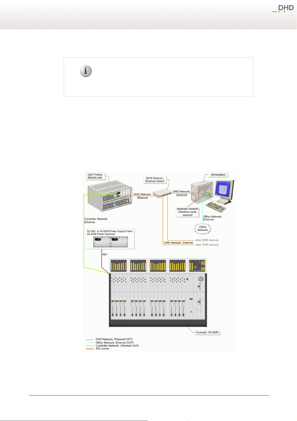
The mixing system consists of two main parts, which are coupled via an industry standard ethernet connection. These
parts are:
· The DSP Frame. This unit includes all input and output modules, the DSP Audio Engine, the Control Engine and the
power supply.
· The Mixing Console. This is the user interface of the mixer with all faders, control knobs, push buttons, displays and
TFT screens.
The following picture should explain the basic structure how to wire a Series 52 mixing system. Of course in reality this is
often much more complex, but the basic idea is always quite the same.
Assembling and Wiring the Hardware
8
DSP Frame and Control Desk coupled via ethernet.
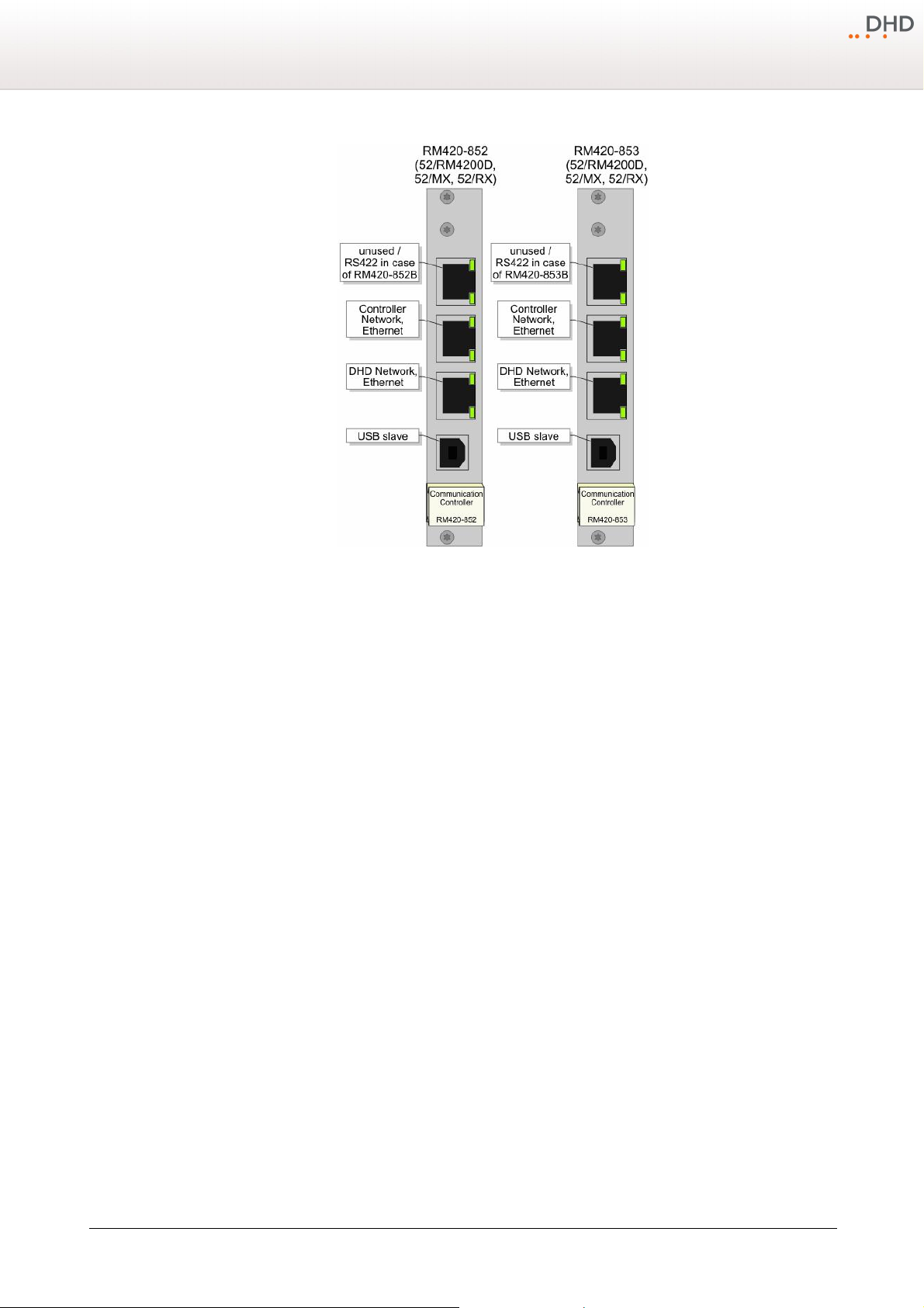
The Communication Controller RM420-852/853 in the DSP frame is the communication interface between the DSP frame
and the connected modules on one side and the ethernet network for configuration and controlling on the other side. You
can find three RJ45 connectors and one USB interface on this module.
Specifications and design are subject to change without notice. The content of this document is for information only. The information presented in this document does not form part
of any quotation or contract, is believed to be accurate and reliable and may be changed without notice. No liability will be accepted by the publisher for any consequence of its use.
Publication thereof does neither convey nor imply any license under patent rights or other industrial or intellectual property rights.
Version 1.10.0 - 17.03.2010
Page 11
9
Manufacturer
Type
3com
Superstack 3, Baseline Switch
16 Port 10/100
Ref. 3C16470
3com
Superstack 3, Baseline Switch
24 Port 10/100
Ref. 3C16471
Allied Telesyn
AT-FS713FC/SC
12x RJ45
1x SC
http://www.alliedtelesyn.de
Allied Telesyn
AT-FS708
8x RJ45
http://www.alliedtelesyn.de
Series 52 - 52/MX Mixing Console Installation Guide
Controller modules for the 52/MX.
Since the revision RM420-852B/853B, the upper RJ45 connector provides an RS422 interface (not useable as RS232). On
previous modules this port has no function.
The middle connector of the three jacks is the interface to the controller network. Connect your console(s) to this RJ45
jack. All modules of this network own an unique IP address, which should not be changed. For configuration and
controlling processes, as well as communication with other DHD Systems, the device can be connected to a PC or a local
network via the lower RJ45 connector. The DHD system can get any IP address in this network.
Use the USB interface of the communication controller module if you want to connect directly to the device for
maintenance.
Finally, the speakon connector of the console needs to be wired with a power supply unit.
General Information
Please use CAT5 cables continuous for wiring. But DHD recommends to use CAT6 cables for longer distances. The
maximum length of the Ethernet cable between two modules of the Controller network is 100 meters (for instance
between the Communication Controller of the DSP frame and a PoE switch or between a PoE switch and 52-4050
Controllers - that are included in the Series 52 console and Q-Panel frames). Use only switches in the DHD network and
the controller network, which are shipped and/or recommended by DHD for the usage in these networks. Especially the
switches must be Unmanaged Switches working with a speed of 100 Mbit/s.
The following switches are tested by DHD and are recommended for the usage in DHD Ethernet networks:
Specifications and design are subject to change without notice. The content of this document is for information only. The information presented in this document does not form part
of any quotation or contract, is believed to be accurate and reliable and may be changed without notice. No liability will be accepted by the publisher for any consequence of its use.
Publication thereof does neither convey nor imply any license under patent rights or other industrial or intellectual property rights.
© 2010 DHD Deubner Hoffmann Digital GmbH
Page 12
5.2.1 Meaning of the Controller Module LEDs
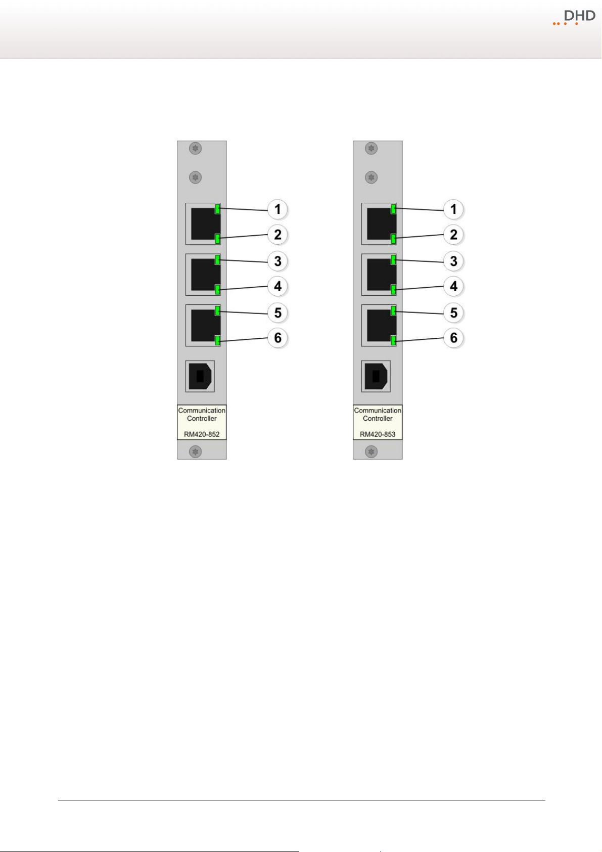
The meaning of the LEDs are identical for the RM420-852 and the RM420-853 Communication Controller modules.
Assembling and Wiring the Hardware
10
Meaning of the LEDs of the RM420-852 and the RM420-853
Communication Controller modules.
1. Reserved for future functions.
2. RM420-852/853: Reserved for future functions. | RM420-852B/853B: Booting process successful ("Done"), must always
turn on several seconds after switching on or resetting the module. During operation, the LED is then permanently
illuminated. On the RM420-852/853 the corresponding LED is located behind the front panel above the USB connector
and is only visible through the little gap.
3. This LED is permanently on if a connection is established to the controller network.
4. The LED flashes during data is received from the controller network.
5. This LED is permanently on if a connection is established to the DHD network.
6. The LED flashes during data is received from the DHD network.
Version 1.10.0 - 17.03.2010
Specifications and design are subject to change without notice. The content of this document is for information only. The information presented in this document does not form part
of any quotation or contract, is believed to be accurate and reliable and may be changed without notice. No liability will be accepted by the publisher for any consequence of its use.
Publication thereof does neither convey nor imply any license under patent rights or other industrial or intellectual property rights.
Page 13
11
Important
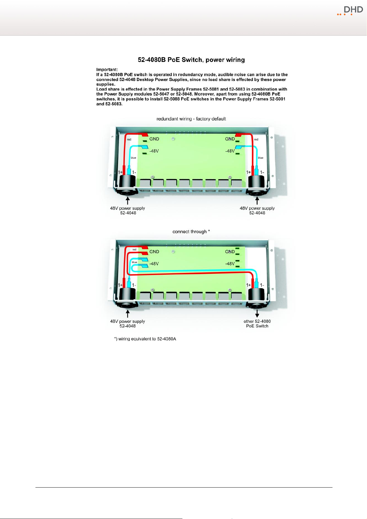
There are two 48V connectors on each 52-4080 PoE switch. At revision A of the
PoE switch (52-4080A), the second speakon connector can be used to chain to
another 52-4080. Do not connect two power supplies to a 52-4080A to achieve
redundant power supply! There is no diode included in the 52-4080A!
Revision B of the PoE switch (52-4080B) provides the option to connect a
redundant power supply to the module. Nevertheless, in revision B it is still
possible to connect through the PoE switch to another PoE switch. Please take
care about the internal wiring!
Series 52 - 52/MX Mixing Console Installation Guide
5.3 Calculating the Power Consumption
The following facts are important for the choice of power supply units for 52/MX Mixing Consoles.
· Use two 52-5048 power supply units for larger mixers with redundancy option inside the 52-5081 or 52-5083 power
supply frames. The maximum power consumption in total is 200W.
· Use two 52-5048 power supply units for several smaller mixers with redundancy option inside the 52-5081 or 52-
5083 power supply frames. The maximum power consumption in total is 200W.
· You may also use two 52-5047 power supply units for smaller mixers with redundancy option inside the 52-5081 or
52-5083 power supply frames. The maximum power consumption in total is 100W.
· Use the 52-4048 desktop power supply for smaller mixers in non redundant installations. The maximum power
consumption in total is 100W.
· PoE switches are not included in all 52-3xxx console or table installation frames.
· Use 52-4080 PoE switches for 52-3xxx frames or 52-5088 PoE switches inside the 52-5083 power supply frames for 52-
3xxx console or table installation frames.
© 2010 DHD Deubner Hoffmann Digital GmbH
Specifications and design are subject to change without notice. The content of this document is for information only. The information presented in this document does not form part
of any quotation or contract, is believed to be accurate and reliable and may be changed without notice. No liability will be accepted by the publisher for any consequence of its use.
Publication thereof does neither convey nor imply any license under patent rights or other industrial or intellectual property rights.
Page 14
Assembling and Wiring the Hardware
12
Power wiring possibilities of the 52-4080 PoE switch.
· PoE switches are included in all 52-4xxx consoles or table installation frames, except 52-4x04.
Please use the following information to calculate the power consumption of your 52/MX Mixing Console.
· Calculate with 10W for each TFT display 52-4015 or 52-4515.
· Calculate with 15W for each controller 52-4050 inside the 52-3xxx or 52-4xxx console or table installation frames.
· If you want to power the loudspeaker amplifiers of the 52-4527 and 52-4424 modules via PoE switches, you have to
calculate 10W for each loudspeaker module.
Example A: 52-4932 (8 controllers 52-4050) equipped with 8 TFTs = 8 x 15W + 8 x 10W = 200W.
Example B: 52-3820 (3 controllers 52-4050) equipped with one TFT and one loudspeaker module = 3 x 15W + 1 x 10W +
1 x 10W = 65W.
Version 1.10.0 - 17.03.2010
Specifications and design are subject to change without notice. The content of this document is for information only. The information presented in this document does not form part
of any quotation or contract, is believed to be accurate and reliable and may be changed without notice. No liability will be accepted by the publisher for any consequence of its use.
Publication thereof does neither convey nor imply any license under patent rights or other industrial or intellectual property rights.
Page 15
13
Series 52 - 52/MX Mixing Console Installation Guide
If you are unsure about the number of controllers 52-4050, please see the controller view pictures in the list of modules
for each console or table installation frame.
© 2010 DHD Deubner Hoffmann Digital GmbH
Specifications and design are subject to change without notice. The content of this document is for information only. The information presented in this document does not form part
of any quotation or contract, is believed to be accurate and reliable and may be changed without notice. No liability will be accepted by the publisher for any consequence of its use.
Publication thereof does neither convey nor imply any license under patent rights or other industrial or intellectual property rights.
Page 16
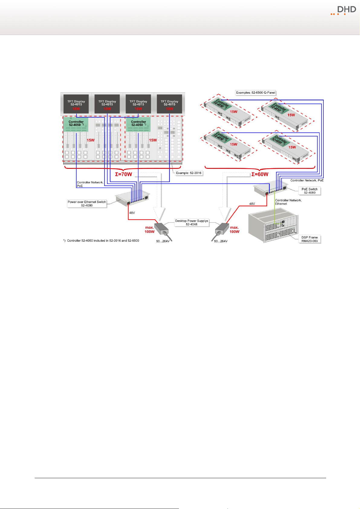
5.3.1 Power Consumption Example 1
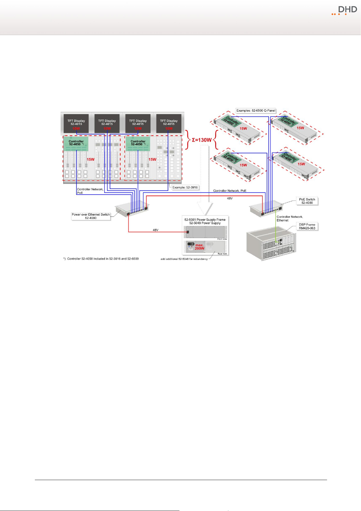
In this example a 52/MX console with two 52-4050 controllers and four TFT displays is used. Calculate 15W for each
controller and 10W for every TFT screen. Consequently, the power consumption of this 52/MX console is about 70W.
Additionally, four Q-Panels are connected to the system. In every Q-Panel one 52-4050 controller is integrated. The power
consumption of all four Q-Panels is about 60W. If you want to use one power supply to power the whole system, this
power supply must provide more than 130W. In this case an 52-5048 power supply is used.
Assembling and Wiring the Hardware
14
Power consumption example 1.
Please see example 2, for a possibility to power the console and the Q-Panels independent.
Version 1.10.0 - 17.03.2010
Specifications and design are subject to change without notice. The content of this document is for information only. The information presented in this document does not form part
of any quotation or contract, is believed to be accurate and reliable and may be changed without notice. No liability will be accepted by the publisher for any consequence of its use.
Publication thereof does neither convey nor imply any license under patent rights or other industrial or intellectual property rights.
Page 17
15
Series 52 - 52/MX Mixing Console Installation Guide
5.3.2 Power Consumption Example 2
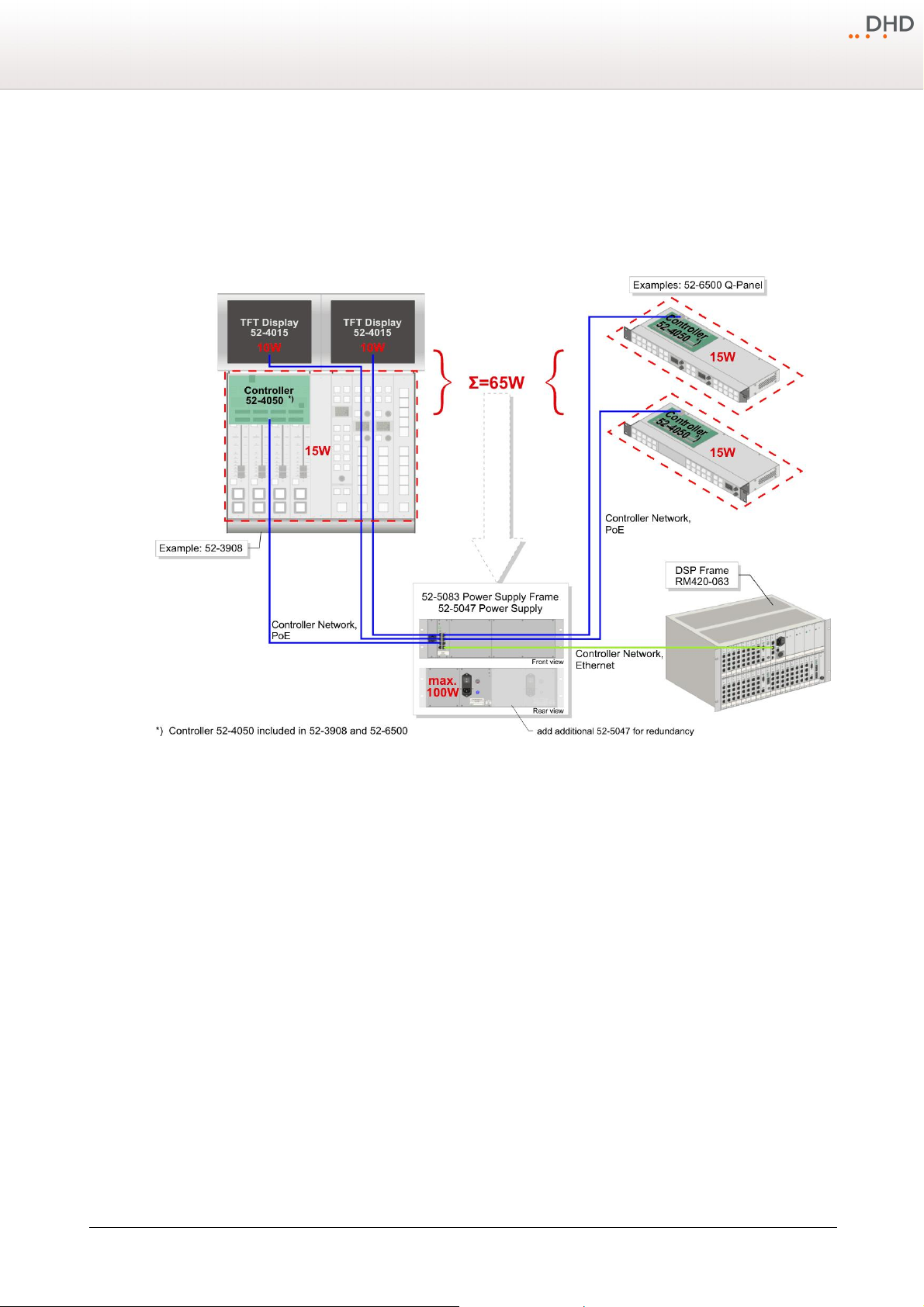
This example is similar to example 1. But in this case the 52/MX console and the Q-Panels are powered independent from
each other. Therefore, two 52-4048 desktop power supplies are used.
Power consumption example 2.
Please see example 1, for a possibility to power the console and the Q-Panels with one power supply.
© 2010 DHD Deubner Hoffmann Digital GmbH
Specifications and design are subject to change without notice. The content of this document is for information only. The information presented in this document does not form part
of any quotation or contract, is believed to be accurate and reliable and may be changed without notice. No liability will be accepted by the publisher for any consequence of its use.
Publication thereof does neither convey nor imply any license under patent rights or other industrial or intellectual property rights.
Page 18
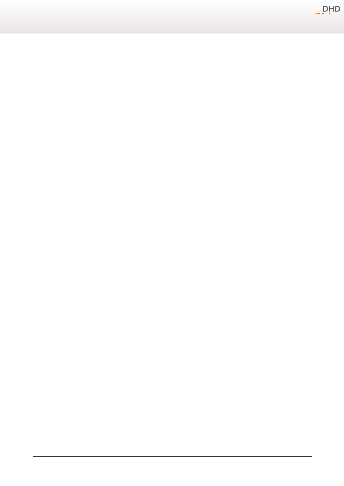
5.3.3 Power Consumption Example 3
In this example a 52/MX console with one 52-4050 controller and two TFT displays is used. Calculate 15W for each
controller and 10W for every TFT screen. Consequently, the power consumption of this 52/MX console is about 35W.
Additionally, two Q-Panels are connected to the system. In every Q-Panel one 52-4050 controller is integrated. The power
consumption of the two Q-Panels is about 30W. Hence, the power supply must provide more than 65W. In this case an
52-5047 power supply is used.
Assembling and Wiring the Hardware
16
Power consumption example 3.
Version 1.10.0 - 17.03.2010
Specifications and design are subject to change without notice. The content of this document is for information only. The information presented in this document does not form part
of any quotation or contract, is believed to be accurate and reliable and may be changed without notice. No liability will be accepted by the publisher for any consequence of its use.
Publication thereof does neither convey nor imply any license under patent rights or other industrial or intellectual property rights.
Page 19
17 Series 52
Index
5
52-4015 TFT screen 6
52-4050 Console Controller 6
52-4080 11
A
Assembling and Wiring the Hardware 6
M
Meaning of the Controller Module LEDs 10
O
operating temperature 6
P
PoE switch 6
Power Consumption 11
C
console frame 6
Controller Module LEDs 10
E
electrostatic discharge 6
Environmental Specifications 6
examples 6
F
flat connectors 6
G
general advices 6
General Information 8
R
RJ45 connector 8
RM420-852 10
RM420-852/853 Communication Controller 8
RM420-853 10
S
speakon 6
System Wiring 8
T
Terms of Use 1
U
USB interface 8
H
humidity 6
© 2010 DHD Deubner Hoffmann Digital GmbH
Page 20
W
Wiring the Console 6
18Index
© 2010 DHD Deubner Hoffmann Digital GmbH
 Loading...