

Page 1
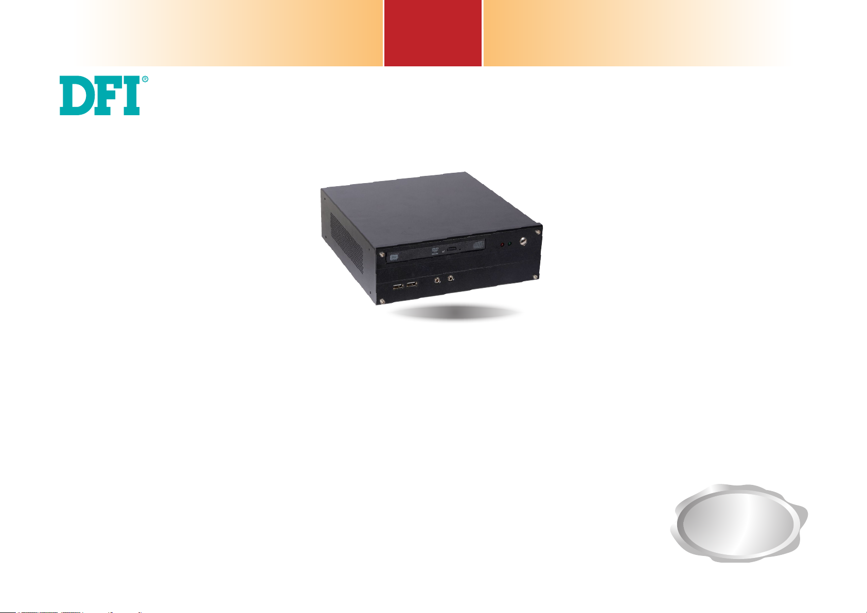
ST102-SD
Desktop Box PC
User’s Manual
Preliminary
Version
A52801917
1
Chapter 1 Introduction www.d.com
Page 2

Copyright
FCC and DOC Statement on Class A
This publication contains information that is protected by copyright. No part of it may be reproduced in any form or by any means or used to make any transformation/adaptation without
the prior written permission from the copyright holders.
This publication is provided for informational purposes only. The manufacturer makes no
representations or warranties with respect to the contents or use of this manual and specifically disclaims any express or implied warranties of merchantability or fitness for any particular purpose. The user will assume the entire risk of the use or the results of the use of this
document. Further, the manufacturer reserves the right to revise this publication and make
changes to its contents at any time, without obligation to notify any person or entity of such
revisions or changes.
Changes after the publication’s first release will be based on the product’s revision. The website will always provide the most updated information.
© 2019. All Rights Reserved.
Trademarks
Product names or trademarks appearing in this manual are for identification purpose only and
are the properties of the respective owners.
This equipment has been tested and found to comply with the limits for a Class A digital
device, pursuant to Part 15 of the FCC rules. These limits are designed to provide reasonable protection against harmful interference when the equipment is operated in a residential
installation. This equipment generates, uses and can radiate radio frequency energy and, if not
installed and used in accordance with the instruction manual, may cause harmful interference
to radio communications. However, there is no guarantee that interference will not occur in a
particular installation. If this equipment does cause harmful interference to radio or television
reception, which can be determined by turning the equipment off and on, the user is encouraged to try to correct the interference by one or more of the following measures:
• Reorient or relocate the receiving antenna.
• Increase the separation between the equipment and the receiver.
• Connect the equipment into an outlet on a circuit different from that to which the receiver
is connected.
• Consult the dealer or an experienced radio TV technician for help.
Notice:
1. The changes or modifications not expressly approved by the party responsible for compli-
ance could void the user’s authority to operate the equipment.
2. Shielded interface cables must be used in order to comply with the emission limits.
2
Chapter 1 Introduction www.d.com
Page 3

Table of Contents
Copyright ................................................................................................2
Trademarks .............................................................................................2
FCC and DOC Statement on Class A ............................................. 2
About this Manual ............................................................................... 4
Warranty ................................................................................................. 4
Static Electricity Precautions ............................................................4
Safety Measures .................................................................................... 4
Safety Precautions ...............................................................................5
About the Package .............................................................................. 5
Before Using the System ................................................................... 5
Chapter 1 - Introduction ...................................................................6
Overview ................................................................................................................................. 6
Key Features .......................................................................................................................... 6
Specifications ........................................................................................................................ 7
Getting to Know the ST102-SD ..................................................................................... 8
Mechanical Dimensions .................................................................................................... 9
Motherboard Dimensions ............................................................................................... 9
Chapter 2 - Getting Started .............................................................. 10
Rear Panel I/O Ports ............................................................................................................ 17
Front Panel I/O Ports .......................................................................................................... 17
RJ45 LAN Ports ................................................................................. 18
USB Ports......................................................................................... 18
Graphics Interfaces ........................................................................... 19
DC-in Jack ........................................................................................ 20
Audio .............................................................................................. 20
I/O Connectors ..................................................................................................................... 21
SATA (Serial ATA) & Power Connectors ................................................ 21
Digital I/O Connector ......................................................................... 21
Cooling Fan Connectors ...................................................................... 22
Expansion Slots ................................................................................ 22
Chassis Intrusion Connector .............................................................. 23
Front Panel Connector ....................................................................... 23
SMBus Connector ............................................................................. 24
S/PDIF Connector .............................................................................. 24
Battery ............................................................................................ 25
Standby Power LED ........................................................................... 25
COM (Serial) Ports ............................................................................ 26
LVDS LCD Panel Connector ................................................................. 27
LCD/Inverter Power Connector ............................................................ 27
Chapter 7 - BIOS Setup ...................................................................... 29
Overview ............................................................................................................................... 29
Insyde BIOS Setup Utility .................................................................. 30
Main .......................................................................................................................................... 30
Advanced .............................................................................................................................. 30
UEFI Device Manager......................................................................... 35
Security ........................................................................................... 39
Boot .......................................................................................................................................... 40
Exit ................................................................................................. 41
Updating the BIOS .............................................................................................................. 41
Notice: BIOS SPI ROM ......................................................................................................... 42
Chapter 7 - Supported Software .................................................... 43
Chapter 3 - Installing Devices .........................................................11
Opening the chassis ........................................................................................................... 11
Installing a Memory Module ........................................................................................... 13
Chapter 4 - Jumper Settings ............................................................ 14
Clear CMOS Data ................................................................................................................. 14
Backlight Power Select ...................................................................................................... 14
Panel Power Select ..............................................................................................................15
Power-on Select ................................................................................................................... 15
COM 1 RS232/Power Select ................................................................ 16
LCD/Inverter Power Select ............................................................................................... 16
Chapter 5 - Ports and Connectors ................................................. 17
3
Chapter 1 Introduction www.d.com
Page 4
About this Manual
Static Electricity Precautions
An electronic file of this manual can be obtained from the DFI website at www.dfi.com. To
download the user’s manual from our website, please go to Support > Download Center. On
the Download Center page, select your product or type the model name and click “Search” to
find all technical documents including the user’s manual for a specific product.
Warranty
1. Warranty does not cover damages or failures that arised from misuse of the product,
inability to use the product, unauthorized replacement or alteration of components and
product specifications.
2. The warranty is void if the product has been subjected to physical abuse, improper installation, modification, accidents or unauthorized repair of the product.
3. Unless otherwise instructed in this user’s manual, the user may not, under any circumstances, attempt to perform service, adjustments or repairs on the product, whether in or
out of warranty. It must be returned to the purchase point, factory or authorized service
agency for all such work.
4. We will not be liable for any indirect, special, incidental or consequential damages to the
product that has been modified or altered.
It is quite easy to inadvertently damage your PC, system board, components or devices even
before installing them in your system unit. Static electrical discharge can damage computer
components without causing any signs of physical damage. You must take extra care in handling them to ensure against electrostatic build-up.
1. To prevent electrostatic build-up, leave the system board in its anti-static bag until you are
ready to install it.
2. Wear an antistatic wrist strap.
3. Do all preparation work on a static-free surface.
4. Hold the device only by its edges. Be careful not to touch any of the components, contacts
or connections.
5. Avoid touching the pins or contacts on all modules and connectors. Hold modules or con
nectors by their ends.
Important:
Electrostatic discharge (ESD) can damage your processor, disk drive and other components. Perform the upgrade instruction procedures described at an ESD workstation only. If such a station is not available, you can provide some ESD protection by
wearing an antistatic wrist strap and attaching it to a metal part of the system chassis. If a wrist strap is unavailable, establish and maintain contact with the system
chassis throughout any procedures requiring ESD protection.
Safety Measures
To avoid damage to the system:
• Use the correct AC input voltage range.
To reduce the risk of electric shock:
• Unplug the power cord before removing the system chassis cover for installation or servic-
ing. After installation or servicing, cover the system chassis before plugging the power cord.
Battery:
• Danger of explosion if battery incorrectly replaced.
• Replace only with the same or equivalent type recommend by the manufacturer.
• Dispose of used batteries according to local ordinance.
4
Chapter 1 Introduction www.d.com
Page 5

Safety Precautions
About the Package
• Use the correct DC input voltage range.
• Unplug the power cord before removing the system chassis cover for installation or servicing. After installation or servicing, cover the system chassis before plugging the power cord.
• Danger of explosion if battery incorrectly replaced.
• Replace only with the same or equivalent type recommend by the manufacturer.
• Dispose of used batteries according to local ordinance.
• Keep this system away from humidity.
• Place the system on a stable surface. Dropping it or letting it fall may cause damage.
• The openings on the system are for air ventilation to protect the system from overheating.
DO NOT COVER THE OPENINGS.
• Place the power cord in such a way that it will not be stepped on. Do not place anything on
top of the power cord. Use a power cord that has been approved for use with the system
and that it matches the voltage and current marked on the system’s electrical range label.
• If the system will not be used for a long time, disconnect it from the power source to avoid
damage by transient overvoltage.
• If one of the following occurs, consult a service personnel:
- The power cord or plug is damaged.
- Liquid has penetrated the system.
- The system has been exposed to moisture.
- The system is not working properly.
The package contains the following items. If any of these items are missing or damaged,
please contact your dealer or sales representative for assistance.
• 1 ST102-SD system unit
• 1 HDD drive bay kit
• 1 Quick Installation Guide
Optional Items
• Power Cord (DC output 12V, 100W)
• Slim optical disc drive (ODD)
• 1 CD disk includes
- Manual
- Drivers
The board and accessories in the package may not come similar to the information listed
above. This may differ in accordance to the sales region or models in which it was sold. For
more information about the standard package in your region, please contact your dealer or
sales representative.
Before Using the System
Before powering-on the system, prepare the basic system components.
If you are installing the system board in a new system, you will need at least the following
internal components.
• Memory module
• Storage devices such as hard disk drive, CD-ROM, etc.
You will also need external system peripherals you intend to use which will normally include at
least a keyboard, a mouse and a video display monitor.
- The system dropped or is damaged.
- The system has obvious signs of breakage.
• The unit uses a three-wire ground cable which is equipped with a third pin to ground the
unit and prevent electric shock. Do not defeat the purpose of this pin. If your outlet does
not support this kind of plug, contact your electrician to replace the outlet.
• Disconnect the system from the DC outlet before cleaning. Use a damp cloth. Do not use
liquid or spray detergents for cleaning.
5
Chapter 1 Introduction www.d.com
Page 6
Chapter 1 - Introduction
Overview
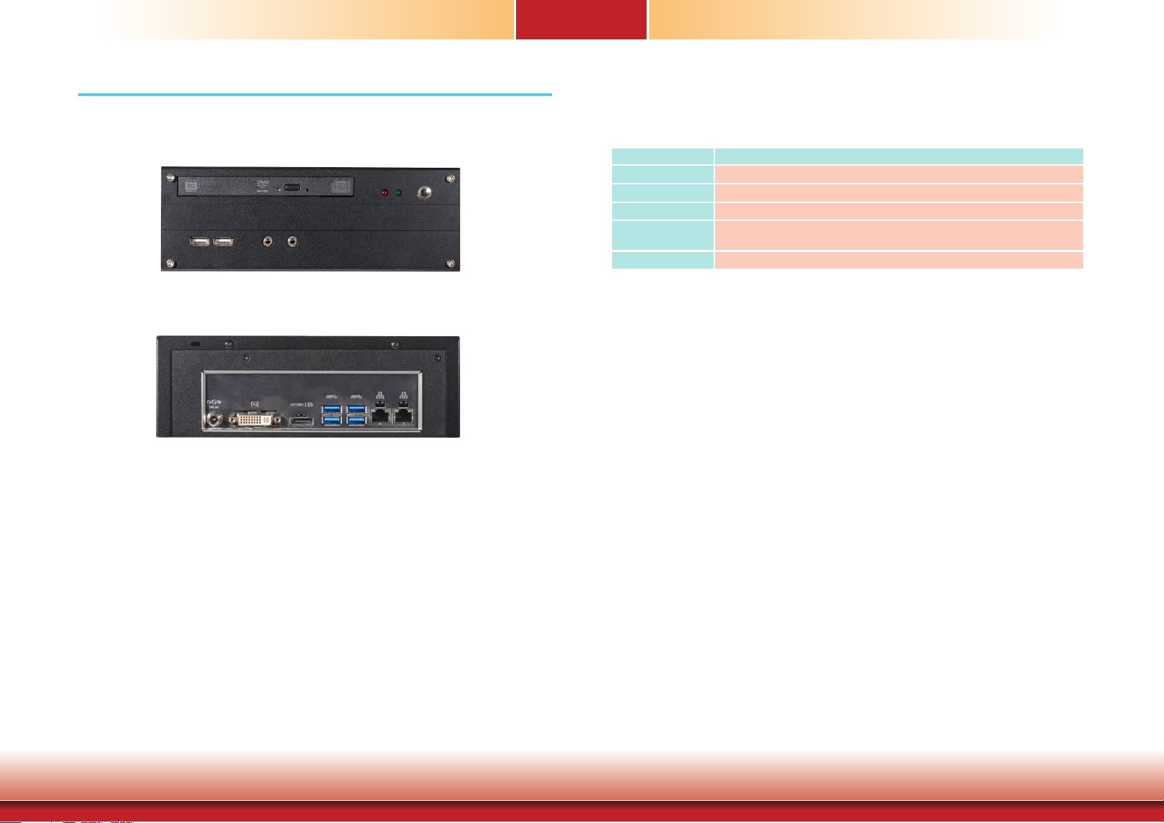
Front View
Chapter 1
Key Features
Model Name ST102-SD
Processor
LAN
Displays
USB
Audio
6th/7th Generation Intel® CoreTM i7/i5/i3 processors
2 LAN ports
1 DP/HDMI (DP available upon request), 1 DVI-D (DVI-I connector)
2 USB 2.0 ports (front)
4 USB 3.0 ports (rear)
Mic-in, Line-out
Rear View
6
Chapter 1 Introduction www.d.com
Page 7

Specifications
Chapter 1
Processor System
Memory
Graphics
Storage
Ethernet
Audio
Power
Cooling System
Processor:
•
6th/7th Generation Intel® CoreTM Processors, LGA 1151 Socket
Intel® Core™ i7-7700T, Quad Core, 8M Cache, 2.9GHz (3.8GHz), 35W
Intel® Core™ i5-7500T, Quad Core, 6M Cache, 2.7GHz (3.3GHz), 35W
Intel® Core™ i3-7101T, Dual Core, 3M Cache, 3.4GHz, 35W
Intel® Celeron® Processor G3930TE, Dual Core, 2M Cache, 2.7GHz, 35W
Intel® Core™ i7-6700TE, Quad Core, 8M Cache, 2.4GHz (3.4GHz), 35W
Intel® Core™ i5-6500TE, Quad Core, 6M Cache, 2.3GHz (3.3GHz), 35W
Intel® Core™ i3-6100TE, Dual Core, 4M Cache, 2.7GHz, 35W
Intel® Pentium® G4400TE, Dual Core, 3M Cache, 2.4GHz, 35W
Intel® Celeron® Processor G3900TE, Dual Core, 2M Cache, 2.6GHz, 35W
• Chipset:
Intel® H110 Express chipset
2 x 260-pin SODIMM (Dual Channel DDR4 1866/2133/2400MHz)
•
• Intel® HD Gen 9 Graphics
• OpenGL 5.0, DirectX 12, OpenCL 2.1
HW Decode: AVC/H.264, MPEG2, VC1/WMV9, JPEG/MJPEG, HEVC/H265, VP8, VP9
HW Encode: MPEG2, AVC/H264, JPEG, HEVC/H265, VP8, VP9
• Displays:
1 x DVI-D (DVI-I connector, resolution up to 1920x1200 @ 60Hz)
1x HDMI (resolution up to 2560x1600 @ 60Hz or 4096x2160 @ 24Hz)
or DP (resolution up to 4096x2304 @ 60Hz)
• Dual Display: DVI-D + DP/HDMI
1 x 2.5" SATA 3.0 Drive Bay
1 x slim ODD Bay (optional)
1 x Intel® I211AT PCIe (10/100/1000Mbps)
1 x Intel® I219V PCIe with iAMT11.0 (10/100/1000Mbps)
Realtek ALC888
• Power type
- DC-in External Power Adapter: DC output 12V 100W, Level 6
1 x System Fan
1 x CPU Fan
I/O Ports
Environment
Construction
Dimensions
Mounting
Weight
OS Support
STANDARDS AND
CERTIFICATIONS
Other Features
• Front Panel
- 1 Power button
- 2 x USB 2.0
- 2 LED indicators: Power, HDD
- Mic-in and line-out jack
• Rear Panel
- 2 x GbE (RJ-45)
- 4 x USB 3.0
- 1 x DVI-D (DVI-I connector)
- 1 x DP (or optional HDMI)
- DC-in Jack
• Temperature
- Operating: 0oC~40oC
- Storage: -20oC~70oC
• Humidity
10 to 85% RH (non-condensing)
-
• Metal chassis + Aluminum front bezel
• 219mm x 77.15mm x 229.7mm (W x H x D)
Desktop/wall mount
TBD
Windows 10 IoT Enterprise 64bit
• Shock
Operating: 3G
Non-operating: 5G
• Vibration
Operating: Random 5~500Hz 1G
Non-operating: Sweep Sine 10~500Hz 1.5G
• Package Drop
ISTA Project 1A
• CE/FCC/VCCI
• Watchdog Timer function;
255 Seconds
System Reset, programmable via software from 1 to
7
Chapter 1 Introduction www.d.com
Page 8
Getting to Know the ST102-SD
Chapter 1
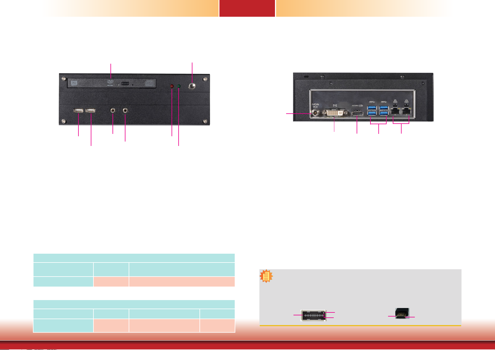
Front View
USB 2.0
USB 2.0
DVD Drive
Line-out
Mic-in
HDD LED
Power Button
Power LED
DVD RW Drive
A Slim Optical Disc Drive (ODD) for reading a disc.
Power Button
(1)
Press to power on or power off the system.
Line-out
Connects a speaker.
Mic-in
Connects an external microphone.
USB Ports (2.0)
Connect USB 2.0/1.1 devices. They comply with USB 2.0 which supports data transmission
rate up to 480 Mbit/s.
HDD LED (flashing red)
Indicates the status of the hard drive.
HDD LED
HDD State
LED Behavior
Disk access
activity
HDD present or HDD not present
Blink Off
Power LED (solid greed)
Indicates the power status of the system.
Power LED
Power Mode power-on Sleep power-off
LED Behavior
Always ON Blink Off
Rear View
DC-in
DVI-D
USB 3.0
DC-in Jack
Connects a DC-in power adapter. Please note the acceptable power range: 12V.
DVI-D Port (DVI-I connector)
Connects to the DVI-D connector of an LCD monitor.
HDMI Port
(2)
Connects to the HDMI port of an LCD monitor.
USB Ports (3.0)
Connect USB 3.0/2.0/1.1 devices. They comply with USB 3.0 which supports data transmission
rate up to 5 Gbits.
LAN Ports
Connect the system to a local area network.
Notes:
1. Please gently press the power button to avoid possible damages.
2. The HDMI is a DP/HDMI combo port but can only transmit HDMI signals (unless wired as a DP
port). Please plug in an HDMI cable with the right orientation and alignment to avoid damage to
the connector. You should feel resistance (due to a pin on the right) if the cable is not inserted
correctly. Please see a video at https://youtu.be/SUj07rfN5l8 for detailed instructions.
Aligning side
(left)
8
Angled-corner
pin
Angled-corner
(up)
LAN PortsDP
Align this edge with the
left side of the connector
Chapter 1 Introduction www.d.com
Page 9
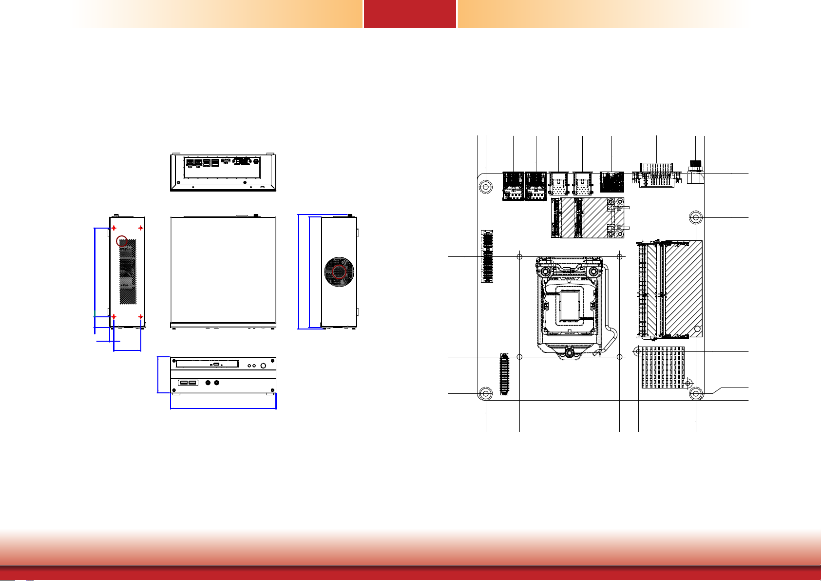
Chapter 1
219
184.30
Mechanical Dimensions
A
22.70
8.50
56
Left View
Rear View
238.16
229.70
Right View
Motherboard Dimensions
0.00
170.00
B
62.48
137.49
69.10
91.07
108.97
125.99
142.94
163.65
35.51
6.33
0.00
33.02
133.42
75.10
165.10
163.65
138.36
63.36
49.31
6.17
165.10
170.00
Front View
9
Chapter 1 Introduction www.d.com
Page 10

Chapter 2
Chapter 2 - Getting Started
Preparing the System
Before you start using the system, you need the following items:
• SATA hard drive
• AC power adapter
• Screwdriver
• Memory modules
Installing Devices
The following devices can be installed in the system.
• Memory module(s)
• SATA hard drive(s)
Configuring the BIOS
To get you started, you may need to change configurations such as the date, time and the
type of hard disk drive.
1. Power on the system.
2. After the memory test, the message “Press DEL to run setup” will appear on the screen.
Press the Delete key to enter the BIOS setup utility.
Installing the Operating System
Depending on the method you choose to install your system, you may use a USB flash drive
or install a CD-ROM drive to run the Operating System CD.
Make sure that a SATA drive is already installed.
1. Refer to the following chapters for information on installing a SATA drive
2. Refer to your operating system manual for instructions on installing an operating system.
Installing the Drivers
The system package includes a CD disk. The CD includes drivers that must be installed to provide the best system performance. Refer to the Supported Software chapter for instructions on
installing the drivers.
10
Chapter 2 Getting Started www.d.com
Page 11
Chapter 3
Chapter 3 - Installing Devices
Import:
To prevent damage to the system board, power down the system and remove all AC
power cords before opening the chassis cover.
Opening the chassis
1. Make sure the system and all other peripheral devices connected to it have been
powered off.
2. Disconnect all power cords and cables.
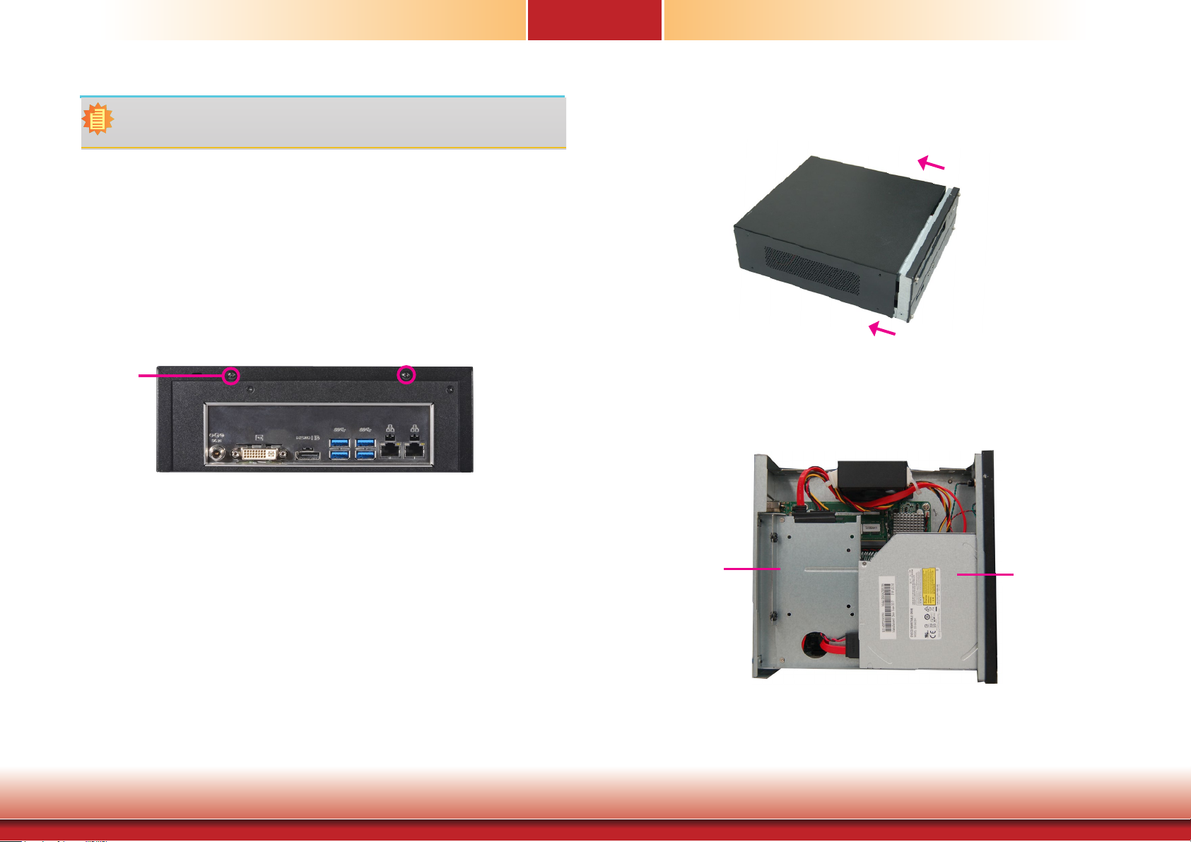
3. The 2 mounting screws on the rear side of the system are used to secure the cover to the
chassis. Remove these screws and then put them in a safe place for later use.
Mounting
screw
4. Slide the cover backwards to open the system.
5. The SODIMM sockets and SATA drive bay are readily accessible after removing the
chassis cover.
Chapter 3 Installing Devices
SATA drive bay
11
ODD drive bay
www.d.com
Page 12

Chapter 3
Installing a 2.5” SATA Drive
The system can accommodate one 2.5” SATA drive. Please use the following procedure to install a 2.5” SATA drive:
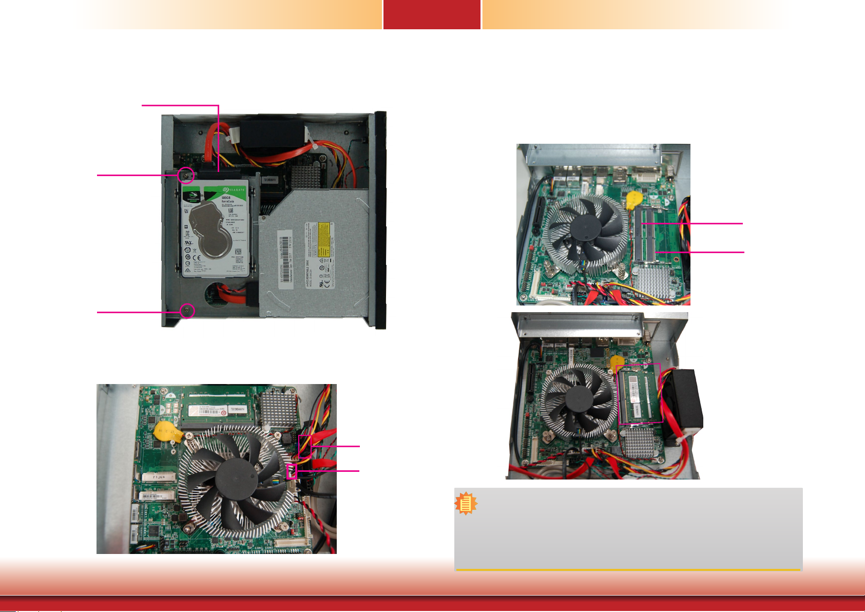
1. Remove the 2 mounting screws that secure the drive bay to the system.
Mounting screw
HDD bracket
Mounting screw
2. Align the mounting holes on the SATA drive with the mounting holes on the HDD bracket.
3. Use the mounting screws provided in the drive bay kit to attach the HDD bracket onto
the drive bay and secure the drive in place.
HDD bracket mounting screws
HDD bracket mounting holes
(on the drive bay’s
bottom side)
SATA mounting screws
Chapter 3 Installing Devices
SATA mounting screws
HDD bracket
Mounting screw
Mounting screw
12
www.d.com
Page 13
Chapter 3
4. Place the SATA drive bay back in the chassis and install the SATA drive bay using the
mounting screws you removed in step 1.
SATA
power/data
cable
Mounting screw
5. Connect the SATA data/power cable to the SATA drive (refer to the above picture). Make
sure the other end of the SATA data/power cable is connected to the connectors on the
system board (refer to the picture below).
Installing a Memory Module
The system board is equipped with two memory slots. Please use the following procedure to
install SODIMM modules.
Grasp the module by its edges and align the memory’s notch with the socket’s notch; then insert the memory into the socket at an angle and push it down until you feel a click.
DIMM1
DIMM2
Chapter 3 Installing Devices
SATA data
connector
SATA power
connector
Notes:
1. The system supports dual-channel configuration. To enable dual-channel,
populate both SODIMM sockets.
2. If installing only one memory module, please install it on the memory socket
labeled DIMM 1 (the one closer to the center of the board).
3. The SODIMM sockets can only accommodate DDR4 memory modules. Please
do not install other types of memory modules.
13
www.d.com
Page 14
Socket LGA1151
2
1
39
40
LVDS LCD Panel
Mini PCIe
mSATA
LAN 1
LAN 2
DC-in
DDR4_2 SODIMM
DDR4_1 SODIMM
HDMI/DP
DVI-D
USB 3-4
USB 3.0
USB 1-2
USB 3.0
S/PDIF
1
10
9
Front Audio
2
1
Buzzer
1
2
Battery
Intel
H110
SPI Flash
BIOS
PCIe 1 (PCIe x4)
10912 10912 10912 10912
COM 2 COM 3 COM 4COM 1
1
1
SATA 0
SATA 3
91210 91210
USB
5-6
USB
7-8
SATA 3.0
1 2
1112
Front
Panel
Digital
I/O
1
USB 2.0
LCD/Inverter
Power
Standby
Power LED
1
System Fan 1
1
1
CPU Fan
Digital
I/O Power
1
SATA
Power
51
62
65
21
3
1
1
1
1
1
1
256
SMBus
Auto Power-on
Select (JP1)
COM 1
RS232/Power
Select (JP2)
LCD/Inverter Power Select (JP7)
Backlight
Power
Select
(JP6)
Panel Power
Select (JP8)
(JP5)
(JP5)
Clear CMOS Data
ASMedia
ASM1442
ASMedia
ASM1442
Intel
WGI211AT
Chassis
Intrusion
ME Disable
1
Chapter 4 - Jumper Settings
Clear CMOS Data
Chapter 4
Backlight Power Select
DC-in
HDMI/DP
USB 3.0
USB 3-4
USB 3.0
USB 1-2
LAN 1
LAN 2
Clear CMOS Data
Auto Power-on
1
Select (JP1)
PCIe 1 (PCIe x4)
DDR4_2 SODIMM
DDR4_1 SODIMM
Socket LGA1151
RS232/Power
Buzzer
Select (JP2)
LCD/Inverter Power Select (JP7)
COM 1
62
51
DVI-D
ASMedia
ASM1442
ASMedia
ASM1442
Mini PCIe
mSATA
Intel
WGI211AT
S/PDIF
Front Audio
9
1
10
2
1
256
1
SMBus
Intel
H110
1
Chassis
Intrusion
CPU Fan
I/O Power
Panel Power
Select (JP8)
1
2
LVDS LCD Panel
10912 10912 10912 10912
COM 2 COM 3 COM 4COM 1
(JP5)
3
ME Disable
(JP5)
SPI Flash
BIOS
SATA 3.0
System Fan 1
SATA
Power
Digital
Power LED
1
1
1
1
1
Standby
Backlight
Power
Select
(JP6)
JP5
1
2
Battery
USB 2.0
USB
USB
5-6
7-8
91210 91210
1
SATA 0
1
SATA 3
1 2
1
Front
Panel
1
1112
1
Digital
I/O
21
65
1
LCD/Inverter
Power
39
40
3
2
1
1-2 On:
Normal (default)
3
2
1
2-3 On:
Clear CMOS Data
If you encounter the following situations, you can reconfigure the system with the default
values stored in the ROM BIOS.
a) CMOS data becomes corrupted.
b) You forgot the supervisor or user password.
1
2
3
1-2 On: +3.3V
JP6
(default)
1
2
3
2-3 On: +5V
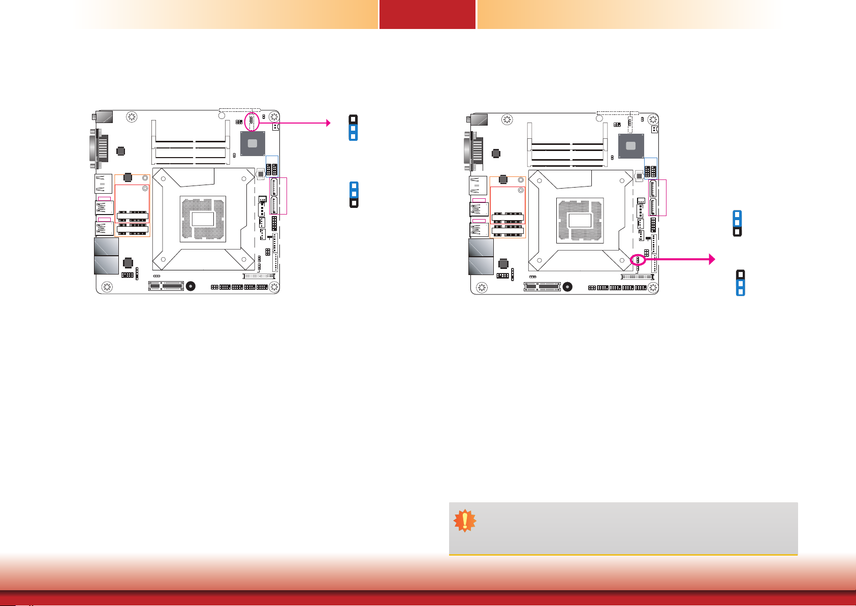
JP6 is used to select the power level of backlight brightness control: +3.3V or +5V.
To load the default values stored in the ROM BIOS, please follow the steps below.
1. Power off the system and unplug the power cord.
2. Set the jumper pins 2 and 3 to On. Wait for a few seconds and set JP5 back to its default
3. Now plug the power cord and power-on the system.
Chapter 4 Jumper Settings
setting, pins 1 and 2 On.
Important:
Before powering on the system, make sure that the power settings of JP6 match the
power specification of backlight control. Selecting the incorrect voltage will seriously
damage the backlight.
14
www.d.comChapter 2 Hardware Installation
Page 15
Chapter 4
PCIe 1 (PCIe x4)
COM 2 COM 3 COM 4COM 1
Panel Power Select
DC-in
Auto Power-on
1
Select (JP1)
PCIe 1 (PCIe x4)
DDR4_2 SODIMM
DDR4_1 SODIMM
HDMI/DP
USB 3.0
USB 3-4
USB 3.0
USB 1-2
LAN 1
LAN 2
DVI-D
ASMedia
ASM1442
Intel
WGI211AT
Front Audio
9
10
ASMedia
ASM1442
Mini PCIe
mSATA
S/PDIF
1
2
1
Socket LGA1151
LCD/Inverter Power Select (JP7)
COM 1
RS232/Power
Buzzer
Select (JP2)
62
51
Clear CMOS Data
1
Chassis
Intrusion
10912 10912 10912 10912
COM 2 COM 3 COM 4COM 1
SMBus
256
1
1
2
(JP5)
3
ME Disable
(JP5)
Intel
H110
SPI Flash
System Fan 1
SATA
Power
CPU Fan
Digital
I/O Power
Panel Power
Select (JP8)
1
1
LVDS LCD Panel
1
BIOS
SATA 3.0
1
1
1
1
Standby
Power LED
Backlight
Power
Select
(JP6)
USB 2.0
USB
7-8
91210 91210
Battery
USB
5-6
1 2
1112
21
65
1
2
1
SATA 0
1
SATA 3
Front
Panel
1
1
39
40
Digital
I/O
LCD/Inverter
Power
JP8
1
3
5
2
4
6
1-2 On: +12V
1
3
5
2
4
6
3-4 On:+5V
1
3
5
5-6 On: +3.3V
2
4
6
(default)
Power-on Select
DC-in
DVI-D
ASMedia
ASM1442
ASMedia
ASM1442
HDMI/DP
USB 3.0
USB 3-4
USB 3.0
Mini PCIe
USB 1-2
mSATA
LAN 1
Intel
WGI211AT
LAN 2
Front Audio
9
10
S/PDIF
1
2
Auto Power-on
1
Select (JP1)
1
DDR4_2 SODIMM
DDR4_1 SODIMM
Socket LGA1151
RS232/Power
Buzzer
Select (JP2)
Clear CMOS Data
256
1
SMBus
1
Chassis
Intrusion
LCD/Inverter Power Select (JP7)
COM 1
10912 10912 10912 10912
62
51
1
2
(JP5)
3
ME Disable
(JP5)
Intel
H110
SPI Flash
BIOS
SATA 3.0
System Fan 1
SATA
Power
CPU Fan
Digital
I/O Power
Panel Power
Select (JP8)
1
1
LVDS LCD Panel
1
1
1
1
1
Standby
Power LED
Backlight
Power
Select
(JP6)
USB
7-8
USB 2.0
91210 91210
Battery
21
65
1
2
USB
5-6
1 2
1112
1
1
SATA 0
1
SATA 3
Front
Panel
1
Digital
I/O
LCD/Inverter
Power
39
40
JP1
31 2
1-2 On:
Power-on via power button
(default)
31 2
2-3 On:
Power-on via AC power
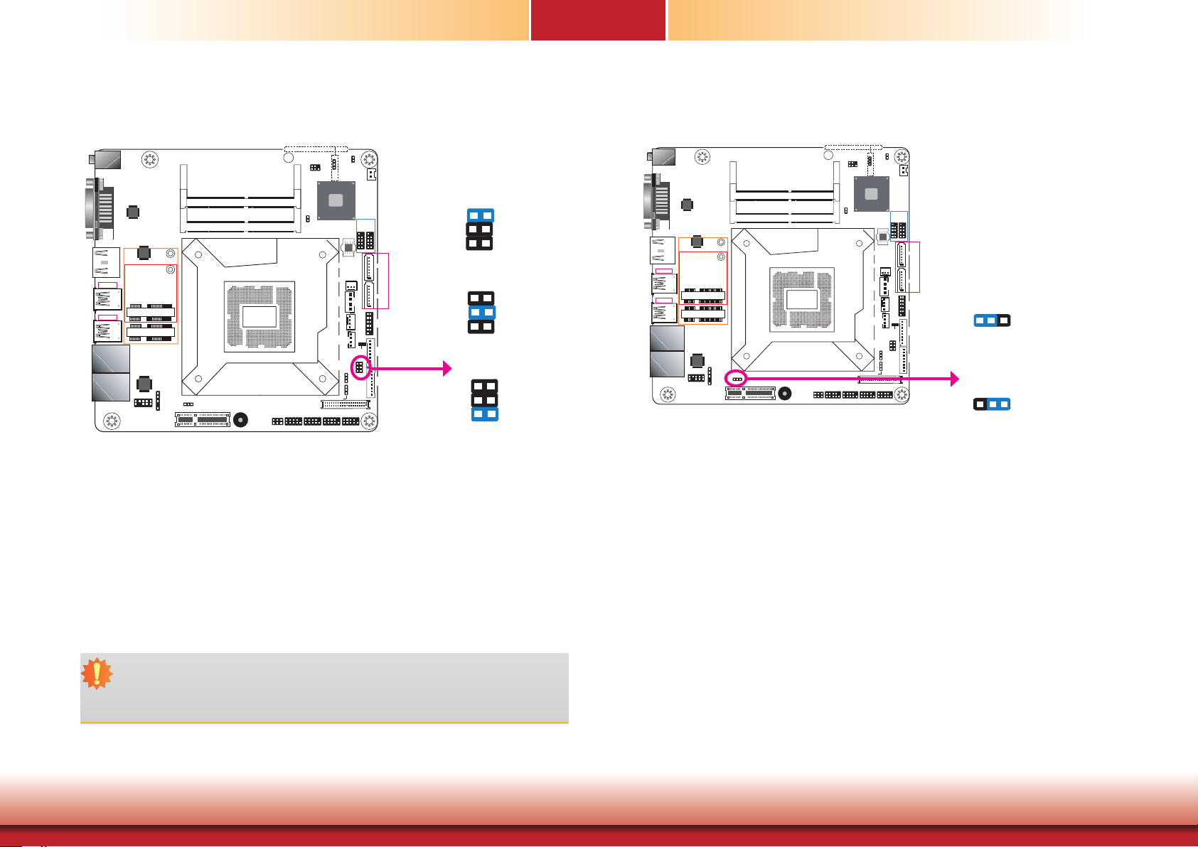
JP8 is used to select the power supplied with the LCD panel.
Important:
Before powering-on the system, make sure that the power settings of JP8 match the
LCD panel’s specification. Selecting the incorrect voltage will seriously damage the
LCD panel.
Chapter 4 Jumper Settings
JP1 is used to select the method of powering on the system. If you want the system to
power-on whenever AC power comes in, set the jumper pins 2 and 3 to On. If you want to
use the power button, set jumper pins 1 and 2 to On.
When using JP1 “Power On” feature to power the system back on after a power failure occurs,
the system may not power on if the power lost is resumed within 5 seconds (power flicker).
15
www.d.comChapter 2 Hardware Installation
Page 16

Chapter 4
PCIe 1 (PCIe x4)
COM 2 COM 3 COM 4COM 1
COM 2 COM 3 COM 4COM 1
(JP5)
Clear CMOS Data
COM 1 RS232/Power Select
DC-in
Auto Power-on
1
Select (JP1)
PCIe 1 (PCIe x4)
DDR4_2 SODIMM
DDR4_1 SODIMM
Socket LGA1151
RS232/Power
Buzzer
Select (JP2)
COM 1
HDMI/DP
USB 3.0
USB 3-4
USB 3.0
USB 1-2
LAN 1
LAN 2
DVI-D
ASMedia
ASM1442
ASMedia
ASM1442
Mini PCIe
mSATA
Intel
WGI211AT
S/PDIF
Front Audio
9
1
10
2
1
JP2 (for COM 1) is designed to configure the Serial COM port to pure RS232 or RS232 with
power. The pin functions of COM 1 will vary according to JP2’s setting respectively.
2
6
256
1
SMBus
Intel
H110
1
Chassis
Intrusion
CPU Fan
I/O Power
LCD/Inverter Power Select (JP7)
1
2
10912 10912 10912 10912
62
51
3
1
ME Disable
(JP5)
SPI Flash
BIOS
SATA 3.0
System Fan 1
1
1
SATA
Power
Digital
Standby
Power LED
Panel Power
Select (JP8)
1
Backlight
Power
Select
1
(JP6)
LVDS LCD Panel
JP2
1
2
Battery
USB 2.0
USB
USB
5-6
7-8
91210 91210
1
SATA 0
1
SATA 3
12
1
Front
Panel
1
1112
1
Digital
JP2
I/O
21
65
1
LCD/Inverter
Power
39
40
RS232/422/485
2
1
6
2
6
2
5
1
COM 1:
10
9
LCD/Inverter Power Select
(JP5)
Clear CMOS Data
DC-in
1
Auto Power-on
Select (JP1)
DDR4_2 SODIMM
DDR4_1 SODIMM
Socket LGA1151
RS232/Power
Buzzer
Select (JP2)
LCD/Inverter Power Select (JP7)
COM 1
62
51
HDMI/DP
USB 3.0
USB 3-4
USB 3.0
USB 1-2
LAN 1
LAN 2
DVI-D
ASMedia
ASM1442
ASMedia
ASM1442
Mini PCIe
mSATA
Intel
WGI211AT
S/PDIF
Front Audio
9
1
10
2
1
JP7 is used to select the power level of LVDS LCD/inverter power connector.
256
1
SMBus
Intel
H110
1
Chassis
Intrusion
CPU Fan
I/O Power
Panel Power
Select (JP8)
1
2
LVDS LCD Panel
10912 10912 10912 10912
3
ME Disable
(JP5)
SPI Flash
BIOS
SATA 3.0
System Fan 1
1
SATA
Power
Digital
Power LED
1
1
1
1
1
Standby
Backlight
Power
Select
(JP6)
1
2
Battery
USB 2.0
USB
USB
5-6
7-8
91210 91210
1
SATA 0
1
SATA 3
12
Front
Panel
1
1112
1
Digital
I/O
21
65
1
LCD/Inverter
JP7
Power
39
40
+12V (default)
2-3 On: +5V
1
2
3
1-2 On:
1
2
3
1
1-3 (RI), 2-4 (DCD) On:
RS232 (default)
RD
2
1 9
DCD
Chapter 4 Jumper Settings
5
1
5
3-5 (+5V), 4-6 (+12V) On:
RS232 with power
COM 1
DSR
RD
DSR
2
1 9
GND
RTS CTS
RI
TD DTR
+12V
GND
RTS CTS
+5V
16
TD DTR
www.d.comChapter 2 Hardware Installation
Page 17
Chapter 5 - Ports and Connectors
Rear Panel I/O Ports
Chapter 5
Front Panel I/O Ports
DC-in Jack
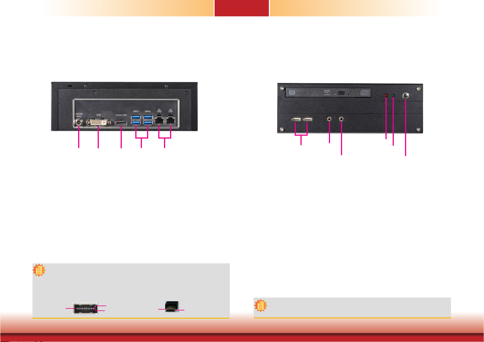
The rear panel I/O ports consist of the following:
• Power Socket:
DC-in Jack
• Ethernet Ports:
Two GbE (RJ-45)
• USB Ports:
Four USB 3.0
• Display ports:
DVI-D (DVI-I connector)
HDMI*
Note:
The HDMI is a DP/HDMI combo port but can only transmit HDMI signals (unless wired as a DP port).
Please plug in an HDMI cable with the right orientation and alignment to avoid damage to the connector. You should feel resistance (due to a pin on the right) if the cable is not inserted correctly. Please
see a video at https://youtu.be/SUj07rfN5l8 for detailed instructions.
Aligning side
(left)
DVI-D
HDMI
Angled-corner
pin
USB 3.0
LAN 1 LAN 2
Angled-corner
(up)
Align this edge with the
left side of the connector
USB 2.0
The front panel I/O ports consist of the following:
• Power button*
• USB Ports:
Two USB 2.0
• Audio Ports:
Microphone & Line-out
• Power and Status LED:
HDD LED
Status LED
Note:
Please gently press the power button to avoid possible damage.
MIC-in
Line-out
HDD
Status
Power Button
Chapter 5 Ports and Connectors
17
www.d.com
Page 18
Chapter 5
PCIe 1 (PCIe x4)
COM 2 COM 3 COM 4COM 1
RJ45 LAN Ports USB Ports
DC-in
DVI-D
HDMI/DP
USB 3.0
USB 3-4
USB 3.0
USB 1-2
LAN 2 LAN 1
Speed
ACT/Link
LAN 1
LAN 2
LAN 1
LAN 2
Front Audio
9
10
Features
• LAN 1: Intel® I219V PCIe (10/100/1000Mbps)
• LAN 2: Intel® I211AT PCIe (10/100/1000Mbps)
ASMedia
ASM1442
ASMedia
ASM1442
Mini PCIe
mSATA
Intel
WGI211AT
Clear CMOS Data
DDR4_2 SODIMM
DDR4_1 SODIMM
Auto Power-on
1
Select (JP1)
PCIe 1 (PCIe x4)
Socket LGA1151
LCD/Inverter Power Select (JP7)
COM 1
RS232/Power
Buzzer
Select (JP2)
62
51
S/PDIF
1
2
1
256
1
SMBus
Intel
H110
1
Chassis
Intrusion
Power
CPU Fan
I/O Power
Panel Power
Select (JP8)
1
2
LVDS LCD Panel
10912 10912 10912 10912
COM 2 COM 3 COM 4COM 1
(JP5)
3
ME Disable
(JP5)
SPI Flash
BIOS
SATA 3.0
System Fan 1
SATA
Digital
Power LED
1
1
1
1
1
Standby
Backlight
Power
Select
(JP6)
1
2
Battery
USB 2.0
USB
USB
5-6
7-8
91210 91210
1
SATA 0
1
SATA 3
1 2
1
Front
Panel
1
1112
1
Digital
I/O
21
65
1
LCD/Inverter
Power
39
40
USB 4
USB 3
USB 3.0
USB 2
USB 1
DC-in
HDMI/DP
USB 3.0
USB 3-4
USB 3.0
USB 1-2
LAN 1
LAN 2
9
10
N.C.
GND
+Data1
-Data1
VCC
DVI-D
ASMedia
ASM1442
ASMedia
ASM1442
Mini PCIe
mSATA
Intel
WGI211AT
S/PDIF
Front Audio
9
1
Auto Power-on
10
1
2
Select (JP1)
1
+Data0
-Data0
VCC
1
2
USB 7-8
DDR4_2 SODIMM
DDR4_1 SODIMM
Socket LGA1151
Buzzer
GND
RS232/Power
Select (JP2)
COM 1
USB 6
USB 2.0
Clear CMOS Data
256
1
SMBus
Intel
H110
1
Chassis
Intrusion
CPU Fan
I/O Power
Panel Power
Select (JP8)
LCD/Inverter Power Select (JP7)
1
2
10912 10912 10912 10912
62
51
(JP5)
3
1
ME Disable
(JP5)
SPI Flash
BIOS
SATA 3.0
System Fan 1
1
1
SATA
Power
Digital
Standby
Power LED
1
Backlight
Power
Select
1
(JP6)
LVDS LCD Panel
USB 5
USB 2.0
1
2
Battery
USB 2.0
USB
USB
5-6
7-8
91210 91210
1
SATA 0
1
SATA 3
1 2
1
Front
Panel
1
1112
1
21
65
1
39
40
Digital
I/O
LCD/Inverter
Power
Activity/Link LED Speed LED
LED Behavior Description LED Behavior Description
Off No link Off 10Mbps connection
Blinking Data Activity Green 100Mbps connection
On Link Orange 1Gbps connection
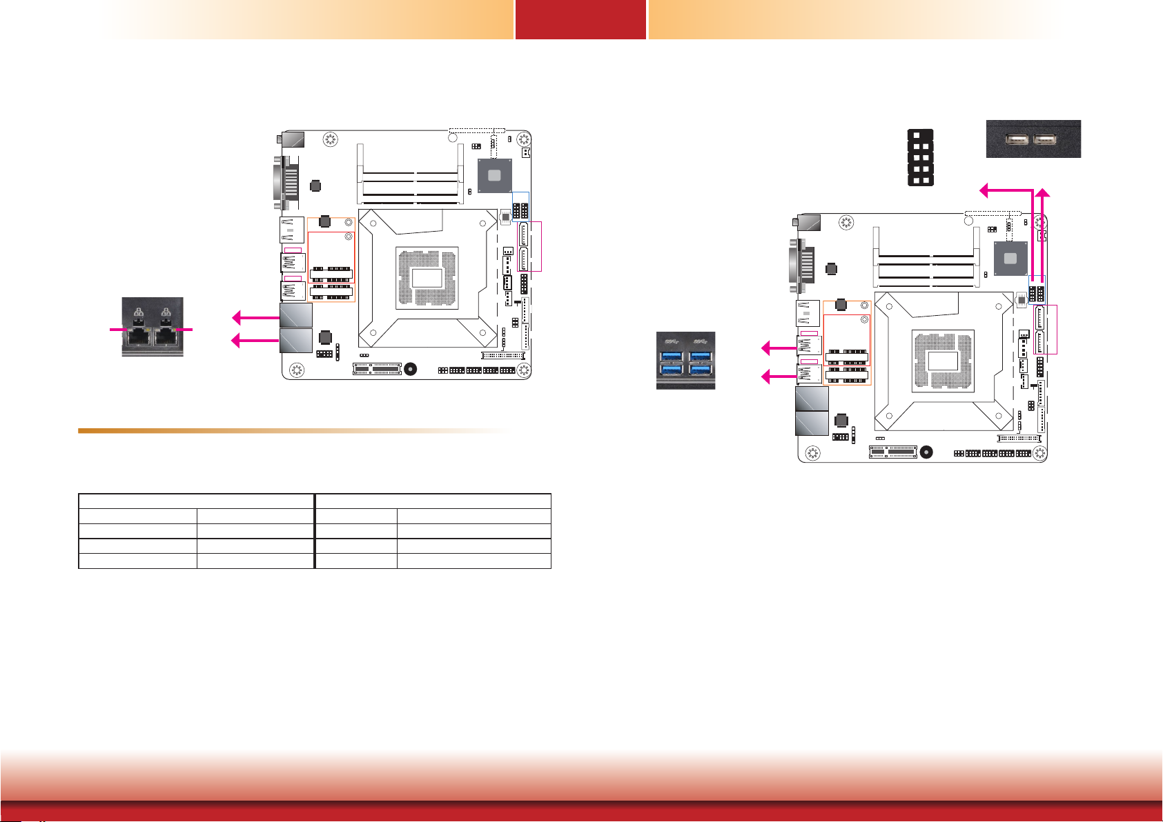
The two LAN ports allow the system board to connect to a local area network with a network hub.
BIOS Setting
Configure the onboard LAN ports in the Advanced menu (“ACPI Configuration” submenu) of the
BIOS. Refer to Chapter 7 - BIOS for more information.
Driver Installation
Install the LAN drivers. Refer to Chapter 8 - Supported Software for more information.
Chapter 5 Ports and Connectors
The USB device allows data exchange between your computer and a wide range of simultaneously accessible external Plug and Play peripherals.
The system board is equipped with four external USB 3.0 ports (USB 1-2/3-4) and two external USB 2.0 ports (USB 5-6). The internal 9-pin connector allows you to connect 2 additional
USB 2.0/1.1 ports (USB 7-8).
18
www.d.com
Page 19
Chapter 5
(JP5)
Clear CMOS Data
BIOS Setting
Configure these onboard USB devices in the Advanced menu (“USB Configuration” submenu)
of the BIOS. Refer to Chapter 7 - BIOS for more information.
Driver Installation
You may need to install the proper drivers in your system operation to use the USB device.
Refer to your operating system’s manual or documentation for more information.
Wake-On-USB Keyboard/Mouse
The Wake-On-USB Keyboard/Mouse function allows you to use a USB keyboard or USB mouse
to wake up a system from the S3 (STR - Suspend To RAM) state.
Important:
If you are using the Wake-On-USB Keyboard/Mouse function for 2 USB ports, the
+5V_standby power source of your power supply must support ≥1.5A. For 3 or more
USB ports, the +5V_standby power source of your power supply must support ≥2A.
Graphics Interfaces
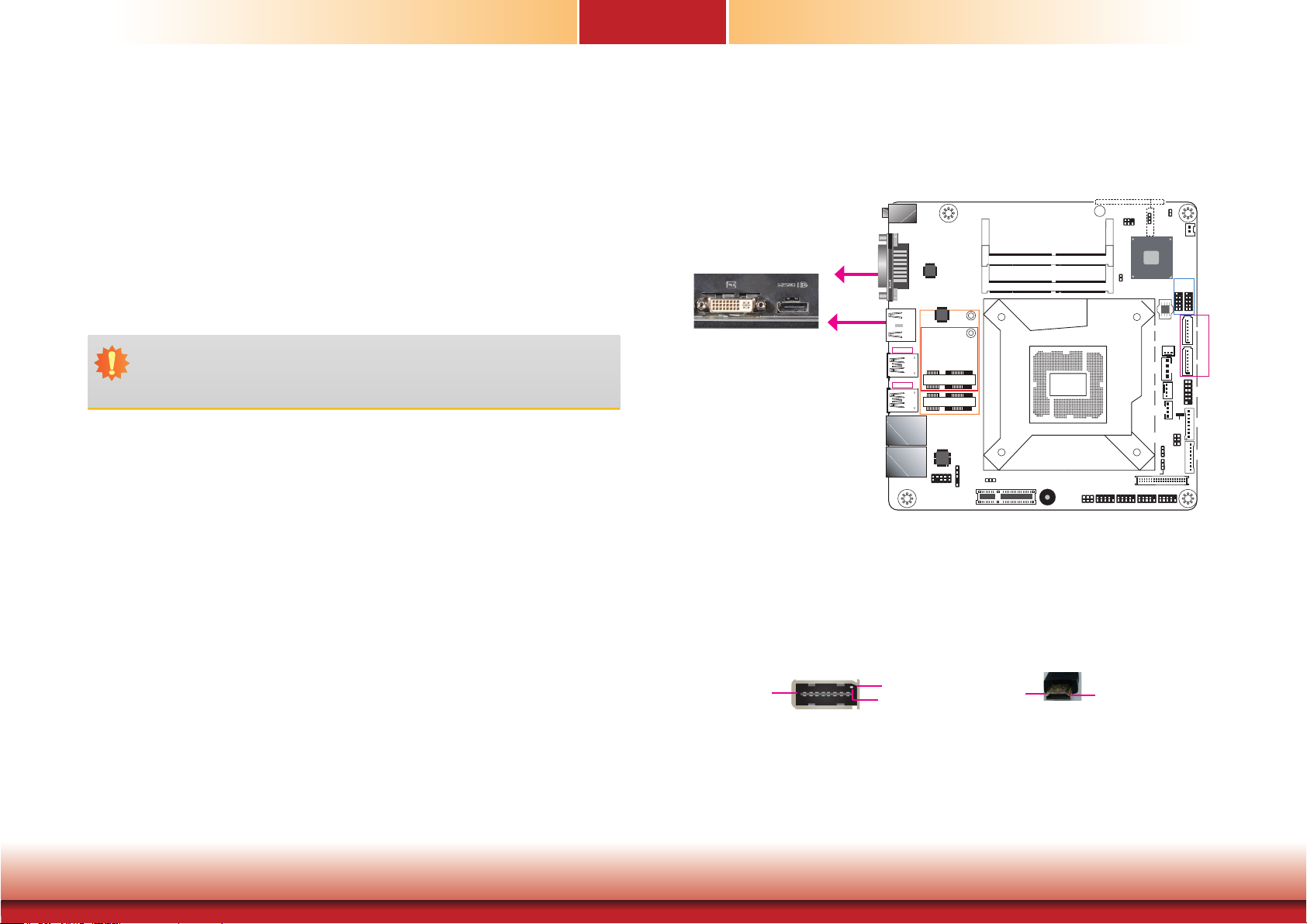
The display ports consist of the following:
• 1 HDMI port
• 1 DVI-D port
DC-in
DVI-D
HDMI
HDMI (or an optional DP Port)
HDMI/DP
USB 3.0
USB 3-4
USB 3.0
USB 1-2
LAN 1
LAN 2
DVI-D
ASMedia
ASM1442
Intel
WGI211AT
Front Audio
9
10
ASMedia
ASM1442
Mini PCIe
mSATA
1
2
S/PDIF
3
1
256
ME Disable
(JP5)
Intel
H110
SPI Flash
BIOS
SATA 3.0
System Fan 1
1
SATA
Power
CPU Fan
Digital
I/O Power
Power LED
Panel Power
Select (JP8)
1
1
LVDS LCD Panel
1
1
Standby
Backlight
Power
Select
(JP6)
1
2
Battery
USB 2.0
USB
USB
5-6
7-8
91210 91210
1
SATA 0
1
SATA 3
1 2
Front
Panel
1
1112
1
Digital
I/O
21
65
1
LCD/Inverter
Power
39
40
1
SMBus
DDR4_2 SODIMM
1
DDR4_1 SODIMM
Chassis
Intrusion
Socket LGA1151
LCD/Inverter Power Select (JP7)
Auto Power-on
1
Select (JP1)
1
PCIe 1 (PCIe x4)
Buzzer
COM 1
RS232/Power
Select (JP2)
10912 10912 10912 10912
62
51
1
2
COM 2 COM 3 COM 4COM 1
Chapter 5 Ports and Connectors
The HDMI (or an optional DisplayPort) is a digital display interface used to connect a display
device such as a computer monitor. Both HDMI and DP can be used to transmit audio and
video data simultaneously. Please note that this is an HDMI/DP combo port but can only transmit HDMI signals (unless wired as a DP port). Please plug in an HDMI cable with the right
orientation and alignment to avoid damage to the connector. You should feel resistance (due
to a pin on the right) if the cable is not inserted correctly. Please see a video at https://youtu.
be/SUj07rfN5l8 for detailed instructions.
Aligning side
(left)
Angled-corner
pin
Angled-corner
(up)
Align this edge with the
left side of the connector
DVI-D (DVI-I connector) Port
The DVI-I port is used to connect an LCD monitor. This port supports DVI-D signals only.
Connect the display device’s cable connector to the DVI-I port. After plugging the cable connector into the port, gently tighten the cable screws to hold the connector in place.
Driver Installation
Install the graphics driver. Refer to Chapter 8 - Supported Software for more information.
19
www.d.com
Page 20
Chapter 5
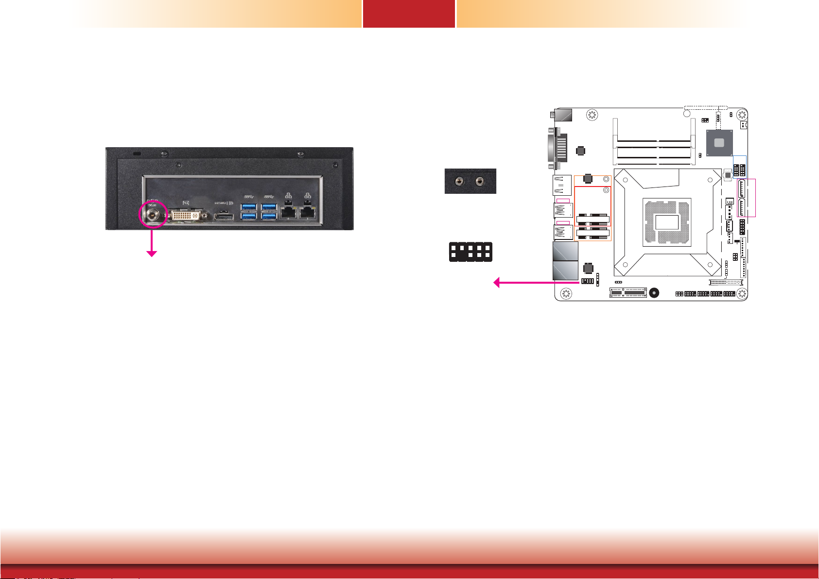
DC-in Jack
DC-in
This jack is considered a low power solution. Connect a DC power cord to this jack. Using a
voltage more than the recommended range (12V only) may fail to boot the system or cause
damage to the system board.
Audio
DC-in
DVI-D
ASMedia
ASM1442
ASMedia
ASM1442
HDMI/DP
Line-out
MIC-in
Line-R
Mic-R
GND
Line-L
9
10
Line-JD
Mic-JD
N.C.
Mic-L
1
2
GND
Front
Audio
Rear Audio
The system board is equipped with 2 audio jacks.
USB 3.0
USB 3-4
USB 3.0
USB 1-2
LAN 1
LAN 2
Intel
WGI211AT
Front Audio
9
10
Mini PCIe
mSATA
1
2
S/PDIF
1
Auto Power-on
1
Select (JP1)
PCIe 1 (PCIe x4)
DDR4_2 SODIMM
DDR4_1 SODIMM
Socket LGA1151
RS232/Power
Buzzer
Select (JP2)
Clear CMOS Data
256
1
SMBus
1
Chassis
Intrusion
LCD/Inverter Power Select (JP7)
COM 1
10912 10912 10912 10912
62
51
COM 2 COM 3 COM 4COM 1
Intel
1
2
(JP5)
3
ME Disable
(JP5)
H110
SPI Flash
BIOS
SATA 3.0
System Fan 1
1
SATA
Power
CPU Fan
Digital
I/O Power
Power LED
Panel Power
Select (JP8)
1
1
LVDS LCD Panel
1
1
1
1
Standby
Backlight
Power
Select
(JP6)
USB 2.0
USB
7-8
Battery
91210 91210
21
65
1
2
USB
5-6
1 2
1112
1
1
SATA 0
1
SATA 3
Front
Panel
1
Digital
I/O
LCD/Inverter
Power
39
40
Chapter 5 Ports and Connectors
• Line-out Jack
This jack is used to connect a headphone or external speakers.
• Microphone-in Jack
This jack is used to connect an external microphone.
BIOS Setting
Configure the audio settings in the Advanced menu (“Audio Configuration” submenu) of the
BIOS. Refer to Chapter 7 - BIOS for more information.
Driver Installation
Install the audio driver. Refer to Chapter 8 - Supported Software for more information.
20
www.d.com
Page 21
Chapter 5
COM 2 COM 3 COM 4COM 1
PCIe 1 (PCIe x4)
COM 2 COM 3 COM 4COM 1
LCD/Inverter
I/O Connectors
SATA (Serial ATA) & Power Connectors
DC-in
HDMI/DP
USB 3.0
USB 3-4
USB 3.0
USB 1-2
LAN 1
LAN 2
DVI-D
ASMedia
ASM1442
Intel
WGI211AT
Front Audio
9
10
ASMedia
ASM1442
Mini PCIe
mSATA
1
2
S/PDIF
Clear CMOS Data
DDR4_2 SODIMM
DDR4_1 SODIMM
Socket LGA1151
Auto Power-on
1
Select (JP1)
1
Buzzer
LCD/Inverter Power Select (JP7)
COM 1
RS232/Power
Select (JP2)
62
51
256
1
SMBus
Intel
H110
1
Chassis
Intrusion
SATA
Power
CPU Fan
I/O Power
Panel Power
Select (JP8)
1
2
LVDS LCD Panel
10912 10912 10912 10912
(JP5)
3
1
ME Disable
(JP5)
SPI Flash
BIOS
SATA 3.0
System Fan 1
1
1
Digital
Power LED
1
Backlight
Power
Select
1
(JP6)
1
1
Standby
USB 2.0
USB
7-8
Battery
91210 91210
21
65
Digital I/O Connector
256
1
SMBus
Intel
H110
1
Chassis
Intrusion
SATA
Power
CPU Fan
I/O Power
Panel Power
Select (JP8)
1
2
LVDS LCD Panel
10912 10912 10912 10912
(JP5)
3
ME Disable
(JP5)
SPI Flash
BIOS
SATA 3.0
System Fan 1
Digital
Power LED
1
1
1
1
2
Battery
USB 2.0
USB
USB
5-6
7-8
91210 91210
1
SATA 0
1
1
1
SATA 3
Digital I/O power
1 2
1
Front
Panel
1
1112
1
Digital I/O
Digital
Standby
I/O
21
65
1
Backlight
LCD/Inverter
Power
Power
Select
(JP6)
39
40
+12V
Ground
5VSB
+5V
1
1
4
LCD/Inverter Power Select (JP7)
COM 1
RS232/Power
Select (JP2)
62
51
Clear CMOS Data
DC-in
SATA
Power
1
2
USB
5-6
1
SATA
SATA 0
Data
1
SATA 3
1 2
Front
Panel
1112
1
Digital
I/O
1
Power
39
40
1
4
SATA 3.0 6Gb/s
SATA 0
SATA 3
1
GND
TXP
TXN
GND
RXN
RXP
7
GND
+12V
Ground
Ground
+5V
Auto Power-on
1
Select (JP1)
PCIe 1 (PCIe x4)
DDR4_2 SODIMM
DDR4_1 SODIMM
Socket LGA1151
Buzzer
HDMI/DP
USB 3.0
USB 3-4
USB 3.0
USB 1-2
LAN 1
LAN 2
DVI-D
ASMedia
ASM1442
ASMedia
ASM1442
Mini PCIe
mSATA
Intel
WGI211AT
S/PDIF
Front Audio
9
1
10
2
1
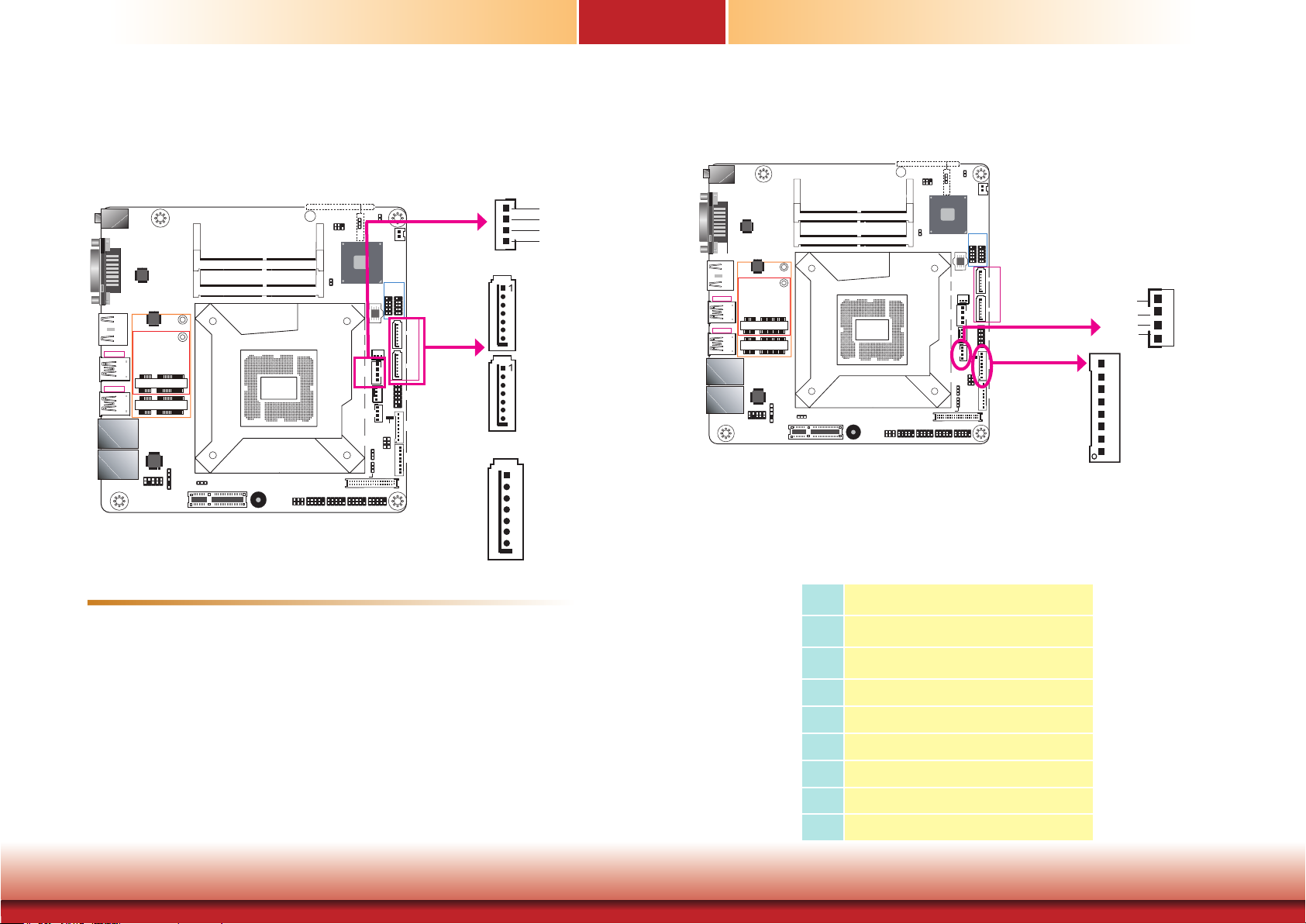
The 8-bit Digital I/O connector provides the ability to monitor and control connected external devices.
Digital I/O Connector
Features
• 2 Serial ATA 3.0 ports with data transfer rate up to 6Gb/s (SATA 0 and SATA 3)
The Serial ATA connectors are used to connect Serial ATA devices. Connect one end of the Serial ATA data cable to a SATA connector and the other end to your Serial ATA device.
BIOS Setting
Configure the Serial ATA drives in the Advanced menu (“SATA Configuration” submenu) of the
BIOS. Refer to Chapter 7 - BIOS for more information.
Chapter 5 Ports and Connectors
Pins Function
1
2
3
4
5
6
7
8
21
DIO7
DIO6
DIO5
DIO4
DIO3
DIO2
DIO1
DIO0
www.d.com
Page 22
Chapter 5
PCIe 1 (PCIe x4)
COM 2 COM 3 COM 4COM 1
PCIe 1 (PCIe x4)
COM 2 COM 3 COM 4COM 1
(JP5)
Clear CMOS Data
Cooling Fan Connectors
256
1
SMBus
Intel
H110
1
Chassis
Intrusion
CPU Fan
I/O Power
Panel Power
Select (JP8)
1
2
LVDS LCD Panel
10912 10912 10912 10912
(JP5)
3
ME Disable
(JP5)
SPI Flash
BIOS
SATA 3.0
System Fan 1
1
1
SATA
Power
Digital
Power LED
1
Backlight
Power
Select
1
(JP6)
1
1
Standby
1
2
Battery
USB 2.0
USB
USB
5-6
7-8
91210 91210
1
SATA 0
1
SATA 3
1 2
Front
Panel
1
1112
1
Digital
I/O
21
65
1
LCD/Inverter
Power
39
40
Clear CMOS Data
LCD/Inverter Power Select (JP7)
COM 1
RS232/Power
Select (JP2)
62
51
1
12V
Ground
Ground
12V
PRM
CTRL
System Fan 1
FAN IN
4
1
CPU Fan
DC-in
HDMI/DP
USB 3.0
USB 3-4
USB 3.0
USB 1-2
LAN 1
LAN 2
DVI-D
ASMedia
ASM1442
Intel
WGI211AT
Front Audio
9
10
ASMedia
ASM1442
Mini PCIe
mSATA
1
2
S/PDIF
DDR4_2 SODIMM
DDR4_1 SODIMM
Socket LGA1151
Auto Power-on
1
Select (JP1)
1
Buzzer
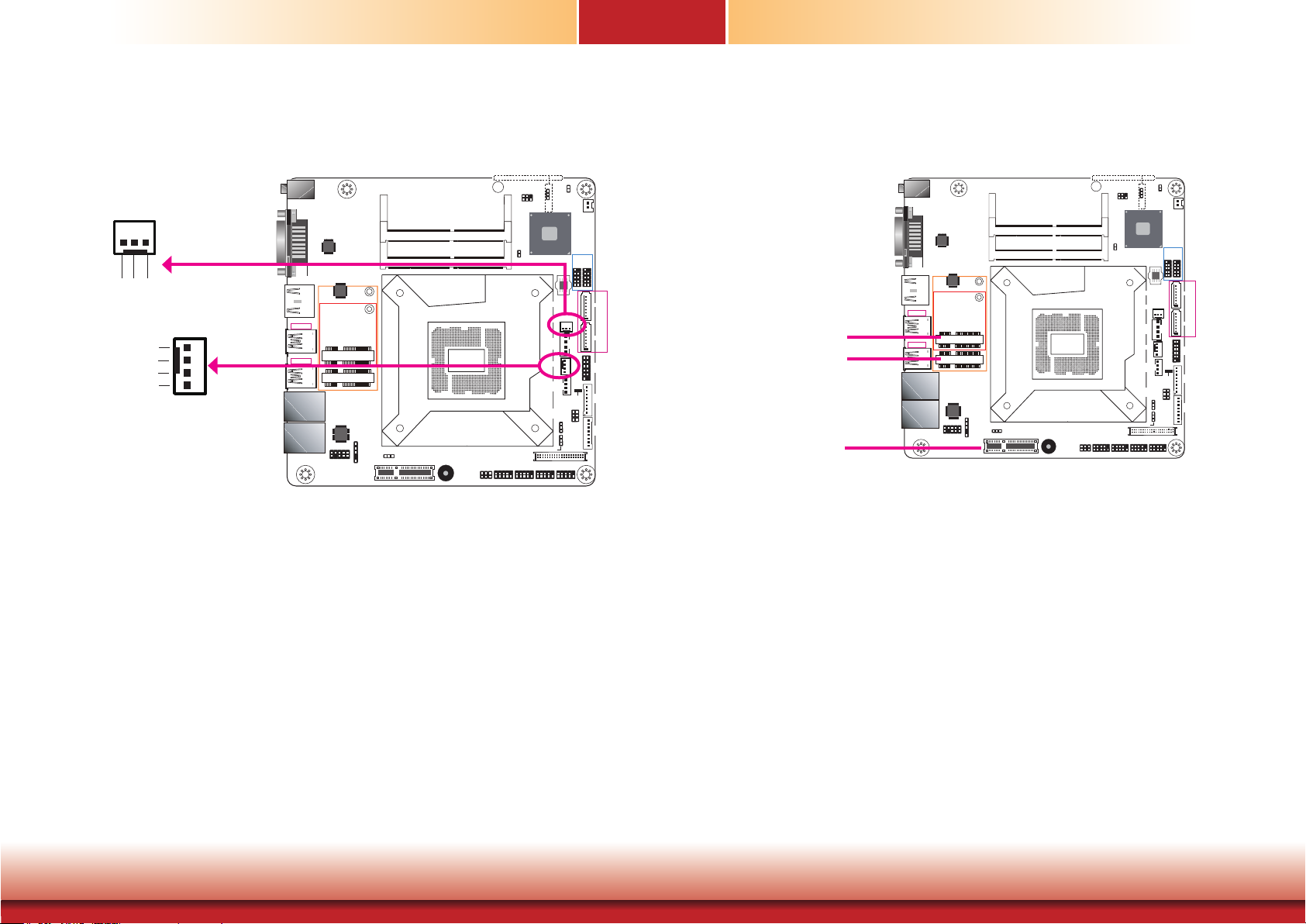
The fan connectors are used to connect cooling fans. The cooling fans will provide adequate
airflow throughout the chassis to prevent overheating the CPU and system board components.
BIOS Setting
Expansion Slots
DC-in
1
Auto Power-on
Select (JP1)
DDR4_2 SODIMM
DDR4_1 SODIMM
Socket LGA1151
RS232/Power
Buzzer
Select (JP2)
LCD/Inverter Power Select (JP7)
COM 1
62
51
Mini PCIe (USB/PCIe)
mSATA (USB/SATA)
PCI Express x4
HDMI/DP
USB 3.0
USB 3-4
USB 3.0
USB 1-2
LAN 1
LAN 2
DVI-D
ASMedia
ASM1442
ASMedia
ASM1442
Mini PCIe
mSATA
Intel
WGI211AT
S/PDIF
Front Audio
9
1
10
2
1
Mini PCI Express Slot
The Mini PCIe socket is used to install a Mini PCIe card. This socket provides PCIe and USB
signals and can support common Wi-Fi and Bluetooth cards or mobile broadband cards.
256
1
SMBus
Intel
H110
1
Chassis
Intrusion
SATA
Power
CPU Fan
I/O Power
Panel Power
Select (JP8)
1
2
LVDS LCD Panel
10912 10912 10912 10912
3
ME Disable
(JP5)
SPI Flash
BIOS
SATA 3.0
System Fan 1
1
1
Digital
Power LED
1
1
1
1
1
Standby
Backlight
Power
Select
(JP6)
USB
7-8
USB 2.0
91210 91210
Battery
21
65
1
2
USB
5-6
1 2
1112
1
1
SATA 0
1
SATA 3
Front
Panel
1
Digital
I/O
LCD/Inverter
Power
39
40
The Advanced menu (“Super IO” submenu) of the BIOS will display the current speed of the
cooling fans. Refer to Chapter 7 - BIOS for more information.
Chapter 5 Ports and Connectors
mSATA Slot (full-size)
The full-size mSATA slot supports SATA III (6Gb/s) transmission rate and is used to connect an
mSATA card. It can expand the system’s storage capacity.
PCI Express x4 Slot
Install PCI Express cards such as network cards or USB expansion cards that comply to the
PCI Express specifications into the PCI Express x4 slot.
22
www.d.com
Page 23
Chapter 5
COM 2 COM 3 COM 4COM 1
Chassis Intrusion Connector
3
256
1
SMBus
Intel
H110
1
Chassis
Intrusion
SATA
Power
CPU Fan
I/O Power
Panel Power
Select (JP8)
1
2
LVDS LCD Panel
10912 10912 10912 10912
(JP5)
1
ME Disable
(JP5)
SPI Flash
BIOS
SATA 3.0
System Fan 1
1
1
Digital
Standby
Power LED
1
Backlight
Power
Select
1
(JP6)
1
2
Battery
USB 2.0
USB
USB
5-6
7-8
91210 91210
1
SATA 0
1
SATA 3
1 2
1
Front
Panel
1
1112
1
Digital
I/O
21
65
1
LCD/Inverter
Power
39
40
LCD/Inverter Power Select (JP7)
COM 1
RS232/Power
Select (JP2)
62
51
Clear CMOS Data
Ground
Signal
2
1
Chassis
Intrusion
DC-in
HDMI/DP
USB 3.0
USB 3-4
USB 3.0
USB 1-2
LAN 1
LAN 2
1
PCIe 1 (PCIe x4)
Auto Power-on
Select (JP1)
DDR4_2 SODIMM
DDR4_1 SODIMM
Socket LGA1151
Buzzer
DVI-D
ASMedia
ASM1442
ASMedia
ASM1442
Mini PCIe
mSATA
Intel
WGI211AT
S/PDIF
Front Audio
9
1
10
2
1
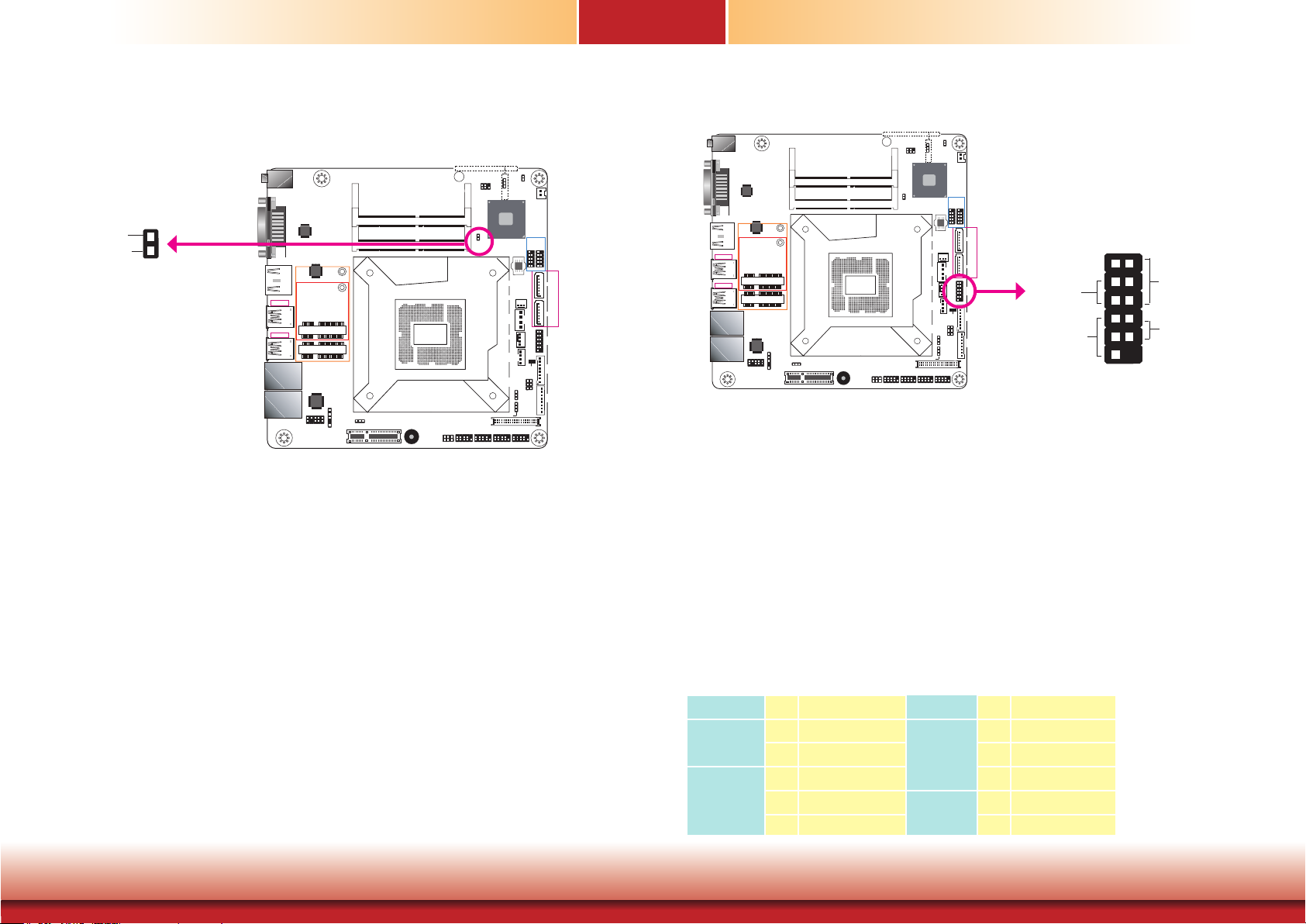
The board supports chassis intrusion detection function. Connect the chassis intrusion sensor
cable from the chassis to this connector. When the system’s power is on and a chassis intrusion event occurs, an alarm will sound. When the system’s power is off and a chassis intrusion
event occurs, the alarm will sound only after the system restarts.
Front Panel Connector
(JP5)
Clear CMOS Data
DC-in
Auto Power-on
1
Select (JP1)
PCIe 1 (PCIe x4)
DDR4_2 SODIMM
DDR4_1 SODIMM
Socket LGA1151
RS232/Power
Buzzer
Select (JP2)
COM 1
HDMI/DP
USB 3.0
USB 3-4
USB 3.0
USB 1-2
LAN 1
LAN 2
DVI-D
ASMedia
ASM1442
ASMedia
ASM1442
Mini PCIe
mSATA
Intel
WGI211AT
S/PDIF
Front Audio
9
1
10
2
1
HDD LED - HDD LED
This LED will be lit when the hard drive is being accessed.
RESET SW - Reset Switch
This switch allows you to reboot without having to power off the system.
ATX SW - ATX Power Switch
This switch is used to power on or off the system.
256
1
SMBus
Intel
H110
1
Chassis
Intrusion
CPU Fan
I/O Power
Panel Power
Select (JP8)
LCD/Inverter Power Select (JP7)
1
2
LVDS LCD Panel
10912 10912 10912 10912
62
51
COM 2 COM 3 COM 4COM 1
3
ME Disable
(JP5)
SPI Flash
System Fan 1
SATA
Power
Digital
1
BIOS
SATA 3.0
1
1
Power LED
1
Backlight
Power
Select
1
(JP6)
Standby
1
2
Battery
USB 2.0
USB
USB
5-6
7-8
91210 91210
1
SATA 0
1
SATA 3
12
1
Front
Front
Panel
Panel
1
1112
1
Digital
I/O
21
65
1
LCD/Inverter
Power
39
40
HDD LED
RESET SW
1
2
PWR LED
ATX SW
1211
Chapter 5 Ports and Connectors
PWR LED - Power/Standby LED
When the system’s power is on, this LED will be lit. When the system is in the S1 (POS - Power On Suspend) state, it will blink every second. When the system is in the S3 (STR - Suspend
To RAM) state, it will blink every 4 seconds.
Pin Pin Assignment Pin Pin Assignment
HDD LED
3 HDD Power
5 Signal 4 LED Power
PWR LED
2 LED Power
7 Ground 6 Signal
RESET SW
9 RST Signal
11 N.C. 10 Signal
ATX SW
23
8 Ground
www.d.com
Page 24
Chapter 5
(JP5)
(JP5)
Clear CMOS Data
SMBus Connector
256
1
SMBus
Intel
H110
1
Chassis
Intrusion
Power
CPU Fan
I/O Power
Panel Power
Select (JP8)
1
2
LVDS LCD Panel
10912 10912 10912 10912
COM 2 COM 3 COM 4COM 1
3
ME Disable
(JP5)
SPI Flash
BIOS
SATA 3.0
System Fan 1
SATA
Digital
1
1
1
1
1
1
1
Standby
Power LED
Backlight
Power
Select
(JP6)
USB 2.0
USB
7-8
Battery
91210 91210
21
65
1
2
USB
5-6
12
1112
1
1
SATA 0
1
SATA 3
Front
Panel
1
Digital
I/O
LCD/Inverter
Power
39
40
HDMI/DP
USB 3.0
USB 3-4
USB 3.0
USB 1-2
DC-in
Auto Power-on
1
Select (JP1)
PCIe 1 (PCIe x4)
DDR4_2 SODIMM
DDR4_1 SODIMM
Socket LGA1151
RS232/Power
Buzzer
LCD/Inverter Power Select (JP7)
COM 1
Select (JP2)
62
51
LAN 1
LAN 2
DVI-D
ASMedia
ASM1442
ASMedia
ASM1442
Mini PCIe
mSATA
Intel
WGI211AT
S/PDIF
Front Audio
9
1
10
2
1
2
1
GND
3V3SB
SMBUS_DataSMBUS_CLK
6
5
SMBUS_Alert
SMBus
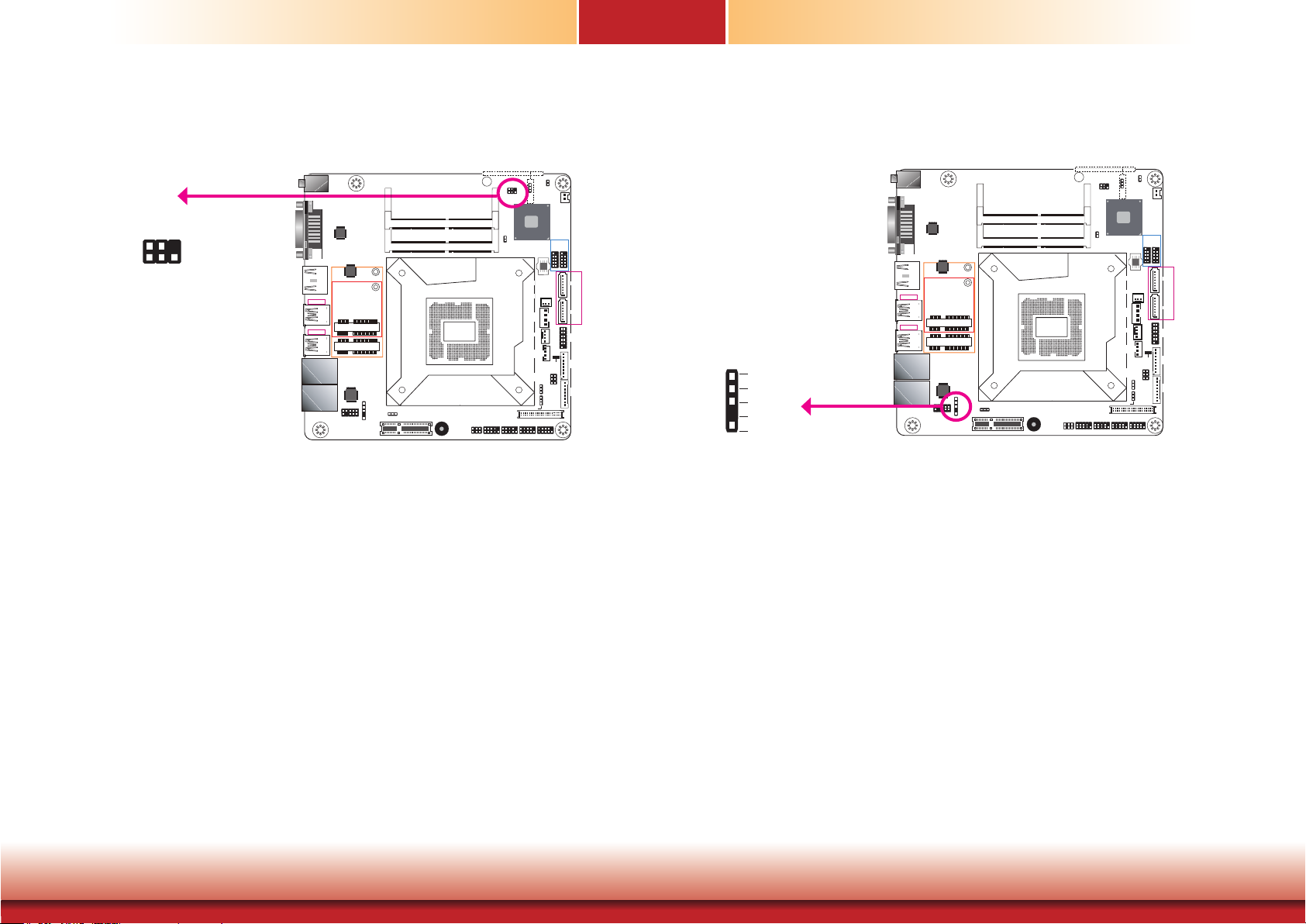
The SMBus (System Management Bus) connector is used to connect low-bandwidth SMBus
devices. It is a multiple device bus that allows multiple chips to connect to the same bus and
enable each one to act as a master by initiating data transfer.
S/PDIF Connector
Clear CMOS Data
DC-in
Auto Power-on
1
Select (JP1)
PCIe 1 (PCIe x4)
DDR4_2 SODIMM
DDR4_1 SODIMM
Socket LGA1151
RS232/Power
Buzzer
LCD/Inverter Power Select (JP7)
COM 1
Select (JP2)
62
51
DVI-D
ASMedia
ASM1442
ASMedia
ASM1442
HDMI/DP
USB 3.0
USB 3-4
USB 3.0
Mini PCIe
USB 1-2
mSATA
LAN 1
LAN 2
Intel
WGI211AT
Front Audio
9
10
S/PDIF
1
2
1
SPIN
5
Ground
SPOUT
NC
1
+5V
S/PDIF
S/PDIF (Sony/Philips Digital Interface Format), a type of digital audio connector, is used for
digital audio transmission or output.
256
1
SMBus
Intel
H110
1
Chassis
Intrusion
CPU Fan
I/O Power
Panel Power
Select (JP8)
1
2
LVDS LCD Panel
10912 10912 10912 10912
COM 2 COM 3 COM 4COM 1
3
ME Disable
(JP5)
SPI Flash
System Fan 1
SATA
Power
Digital
1
1
1
BIOS
SATA 3.0
1
1
1
Standby
Power LED
Backlight
Power
Select
(JP6)
1
2
Battery
USB 2.0
USB
USB
5-6
7-8
91210 91210
1
SATA 0
1
SATA 3
12
Front
Panel
1
1112
1
Digital
I/O
21
65
1
LCD/Inverter
Power
39
40
Chapter 5 Ports and Connectors
24
www.d.com
Page 25
Chapter 5
COM 2 COM 3 COM 4COM 1
PCIe 1 (PCIe x4)
COM 2 COM 3 COM 4COM 1
LCD/Inverter
Battery
(JP5)
Clear CMOS Data
DC-in
1
Auto Power-on
Select (JP1)
DDR4_2 SODIMM
DDR4_1 SODIMM
Socket LGA1151
RS232/Power
Buzzer
Select (JP2)
LCD/Inverter Power Select (JP7)
COM 1
62
51
HDMI/DP
USB 3.0
USB 3-4
USB 3.0
USB 1-2
LAN 1
LAN 2
DVI-D
ASMedia
ASM1442
ASMedia
ASM1442
Mini PCIe
mSATA
Intel
WGI211AT
S/PDIF
Front Audio
9
1
10
2
1
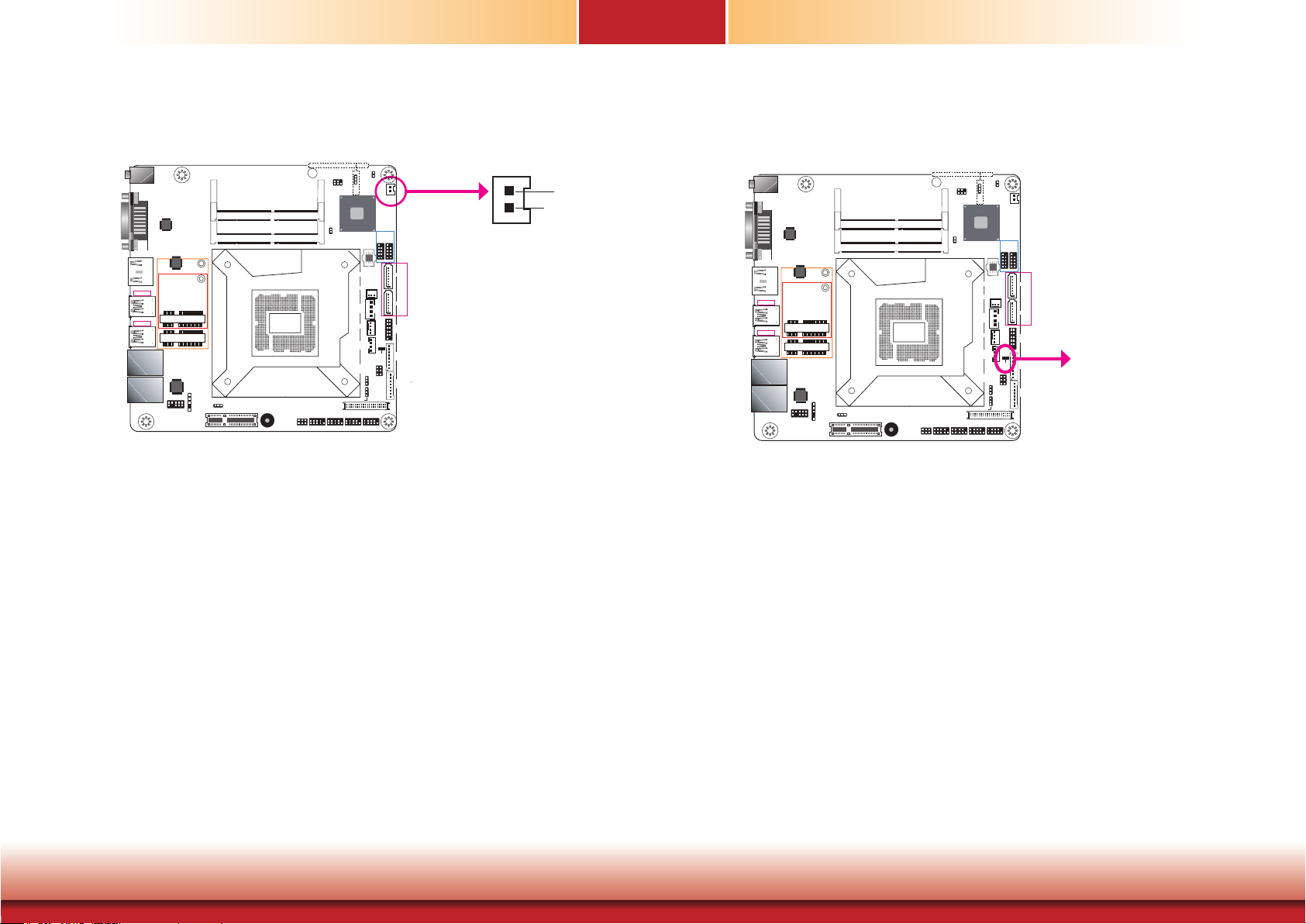
The lithium ion battery powers the real-time clock and CMOS memory. It is an auxiliary source
of power when the main power is shut off.
Safety Measures
256
1
SMBus
Intel
H110
1
Chassis
Intrusion
SATA
Power
CPU Fan
I/O Power
Panel Power
Select (JP8)
1
2
LVDS LCD Panel
10912 10912 10912 10912
3
ME Disable
(JP5)
SPI Flash
BIOS
SATA 3.0
System Fan 1
1
Digital
Power LED
1
1
1
1
Backlight
Power
Select
(JP6)
1
1
Standby
Battery
1
2
Battery
USB 2.0
USB
USB
5-6
7-8
91210 91210
1
SATA 0
1
SATA 3
12
Front
Panel
1112
1
Digital
I/O
21
65
1
Power
39
40
1
2
+3.3V
GND
Standby Power LED
(JP5)
Clear CMOS Data
DC-in
Auto Power-on
1
Select (JP1)
PCIe 1 (PCIe x4)
DDR4_2 SODIMM
DDR4_1 SODIMM
Socket LGA1151
RS232/Power
Buzzer
LCD/Inverter Power Select (JP7)
COM 1
Select (JP2)
62
51
HDMI/DP
USB 3.0
USB 3-4
USB 3.0
USB 1-2
LAN 1
LAN 2
DVI-D
ASMedia
ASM1442
ASMedia
ASM1442
Mini PCIe
mSATA
Intel
WGI211AT
S/PDIF
Front Audio
9
1
10
2
1
This LED will be red when the system is in the standby mode. It indicates that there is power
on the system board. Power off the system and then unplug the power cord prior to installing
any devices. Failure to do so will cause severe damage to the motherboard and components.
256
1
SMBus
Intel
H110
1
Chassis
Intrusion
CPU Fan
I/O Power
Panel Power
Select (JP8)
1
2
LVDS LCD Panel
10912 10912 10912 10912
3
ME Disable
(JP5)
SPI Flash
System Fan 1
SATA
Power
Digital
1
1
1
BIOS
SATA 3.0
1
1
Power LED
Backlight
Power
Select
(JP6)
1
1
Standby
USB
7-8
USB 2.0
1
2
Battery
USB
5-6
91210 91210
1
SATA 0
1
SATA 3
12
Front
Panel
1112
21
65
1
1
39
40
Digital
I/O
LCD/Inverter
Power
Standby Power LED
• Danger of explosion if battery incorrectly replaced.
• Replace only with the same or equivalent type recommend by the manufacturer.
• Dispose of used batteries according to local ordinance.
Chapter 5 Ports and Connectors
25
www.d.com
Page 26
Chapter 5
PCIe 1 (PCIe x4)
COM 2 COM 3 COM 4COM 1
COM (Serial) Ports
DC-in
DVI-D
ASMedia
ASM1442
ASMedia
ASM1442
HDMI/DP
USB 3.0
USB 3-4
USB 3.0
Mini PCIe
USB 1-2
mSATA
LAN 1
Intel
WGI211AT
LAN 2
Front Audio
9
10
DDR4_2 SODIMM
DDR4_1 SODIMM
S/PDIF
1
2
Auto Power-on
1
Select (JP1)
1
2
1
COM 1: RS232/422/485
Socket LGA1151
LCD/Inverter Power Select (JP7)
COM 1
RS232/Power
Buzzer
Select (JP2)
62
51
10
COM 1
9
Clear CMOS Data
SMBus
1
Chassis
Intrusion
10912 10912 10912 10912
COM 2
256
1
1
2
COM 3
(JP5)
3
ME Disable
(JP5)
Intel
H110
SPI Flash
SATA 3.0
System Fan 1
SATA
Power
CPU Fan
Digital
I/O Power
Panel Power
Select (JP8)
1
1
LVDS LCD Panel
COM 4
1
BIOS
1
1
1
1
Standby
Power LED
Backlight
Power
Select
(JP6)
USB 2.0
USB
7-8
Battery
91210 91210
21
65
1
2
USB
5-6
1 2
1112
1
1
SATA 0
1
SATA 3
Front
Panel
1
Digital
I/O
LCD/Inverter
Power
39
40
COM 2/3/4: RS232
RD
DSR
2
1 9
TD DTR
GND
RTS CTS
DCD
COM 1
RD
DTR
DSR
CTS
2
1
TD
DCD
GND
9
RI
RTS
RS232
RX-
TX-
2
1
RX+
TX+
RS422
Full Duplex
N.C.
GND
N.C.
N.C.
9
N.C.
DATA-
N.C.
N.C.
N.C.
2
1
N.C.
GND
N.C.
9
N.C.
DATA+
RS485
RI
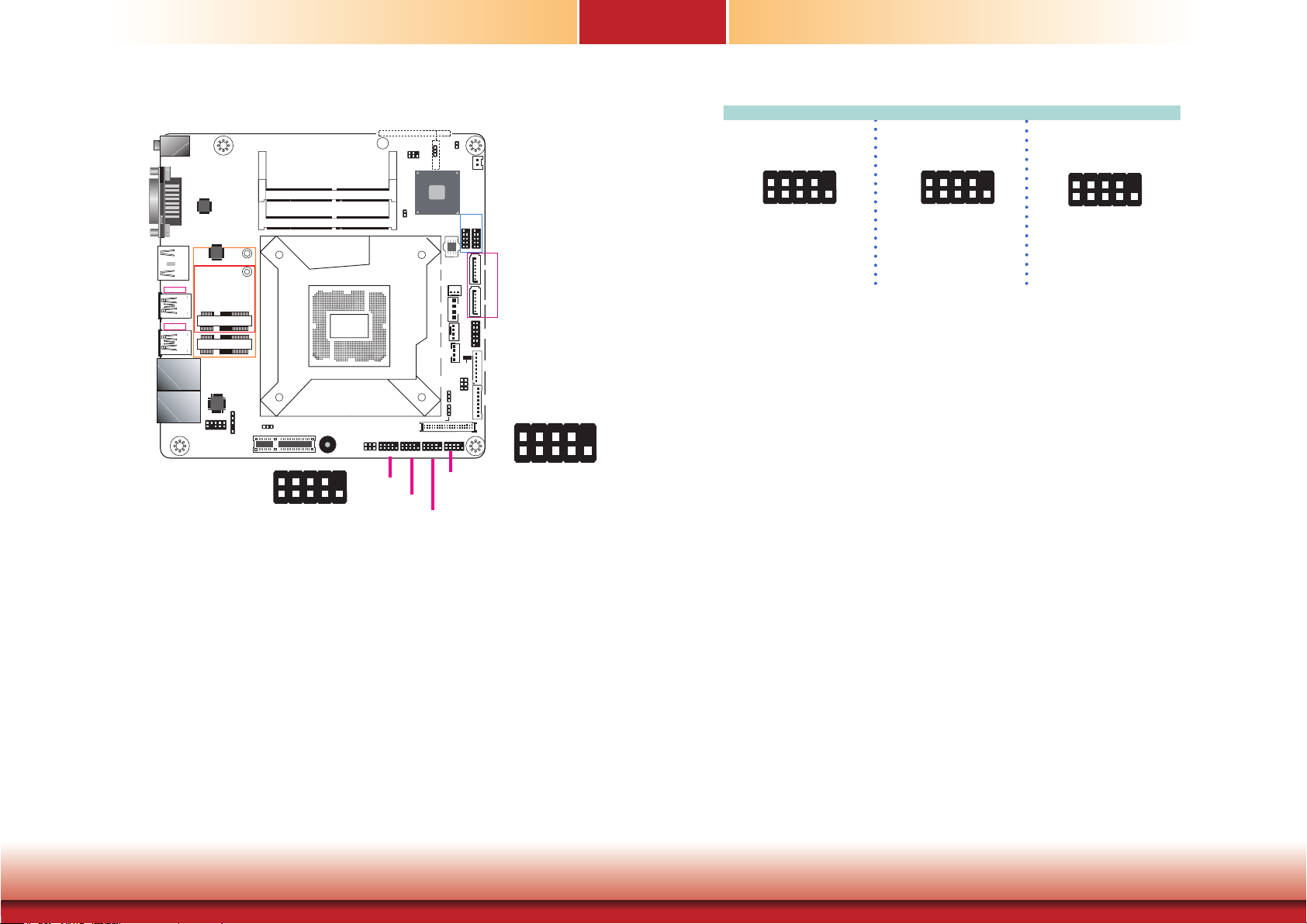
The pin functions of COM 1 will vary according to BIOS’ setting. JP2 (for COM1) is designed to
configure Serial COM port to pure RS232 or RS232 with power. Refer to “COM 1 RS232/Power
Select” in Chapter 4 for more information.
COM 2, COM 3 and COM 4 are fixed at RS232.
The serial ports are asynchronous communication ports with 16C550A-compatible UARTs that
can be used with modems, serial printers, remote display terminals, and other serial devices.
Connecting External Serial Ports
Your COM port may come mounted on a card-edge bracket. Install the card-edge bracket to
an available slot at the rear of the system chassis then insert the serial port cable to the COM
connector. Make sure the colored stripe on the ribbon cable is aligned with pin 1 of the COM
connector.
BIOS Setting
Configure the serial COM ports including the communication mode in the Advanced menu
(“SIO NUVOTON6106D” submenu) of the BIOS. Refer to Chapter 7 for more information.
Chapter 5 Ports and Connectors
26
www.d.com
Page 27
Chapter 5
PCIe 1 (PCIe x4)
COM 2 COM 3 COM 4COM 1
LVDS LCD Panel Connector
LCD/Inverter Power Connector
(JP5)
Clear CMOS Data
DC-in
1
Auto Power-on
Select (JP1)
DDR4_2 SODIMM
DDR4_1 SODIMM
Socket LGA1151
RS232/Power
Buzzer
Select (JP2)
LCD/Inverter Power Select (JP7)
COM 1
62
51
HDMI/DP
USB 3.0
USB 3-4
USB 3.0
USB 1-2
LAN 1
LAN 2
DVI-D
ASMedia
ASM1442
ASMedia
ASM1442
Mini PCIe
mSATA
Intel
WGI211AT
S/PDIF
Front Audio
9
1
10
2
1
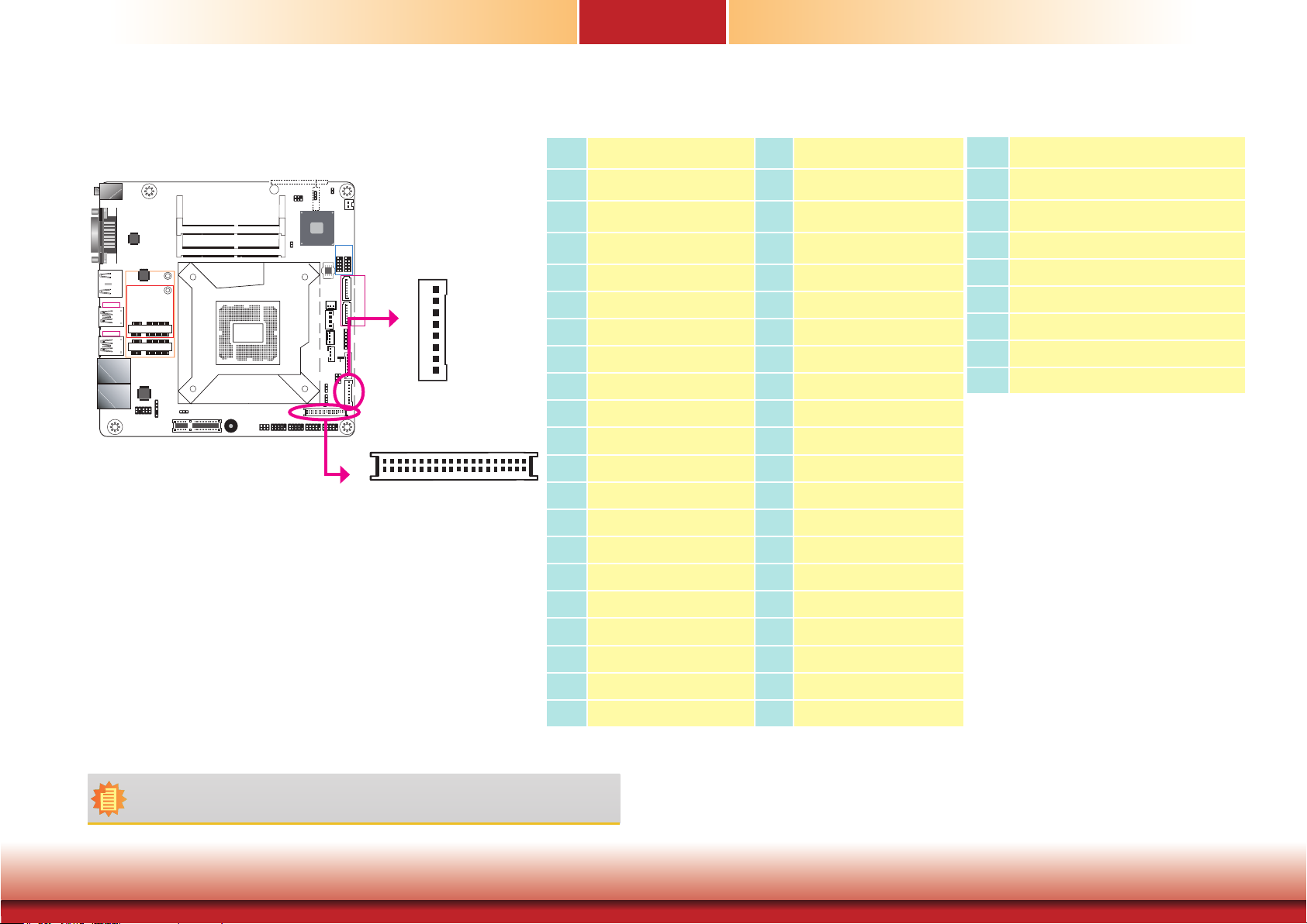
The system board allows you to connect an LCD panel with the LVDS LCD panel
connector and the LCD/Inverter Power connector. These connectors transmit
video signals and power from the system board to the LCD panel.
Refer to the right side for the pin functions of these connectors.
BIOS Setting
Configure the LCD panel in the Advanced menu (“Video Configuration” submenu) of the BIOS. Refer to Chapter 7 for more information.
256
1
SMBus
Intel
H110
1
Chassis
Intrusion
CPU Fan
I/O Power
Panel Power
Select (JP8)
1
2
LVDS LCD Panel
10912 10912 10912 10912
3
ME Disable
(JP5)
SPI Flash
SATA 3.0
System Fan 1
SATA
Power
Digital
1
1
1
BIOS
1
1
1
Standby
Power LED
Backlight
Power
Select
(JP6)
1
2
Battery
USB 2.0
USB
USB
5-6
7-8
91210 91210
LCD/Inverter Power
1
SATA 0
1
SATA 3
12
Front
Panel
1
1112
1
Digital
I/O
21
65
1
LCD/Inverter
Power
39
40
1
2
LVDS LCD Panel
1
8
39
40
LVDS LCD Panel Connector
Pin Function Pin Function
GND
1
LVDS_Out3+ (Odd_3+)
3
LVDS_Out3- (Odd_3-)
5
GND
7
LVDS_Out2+ (Odd_2+)
9
LVDS_Out2- (Odd_2-)
11
GND
13
LVDS_Out1+ (Odd_1+)
15
LVDS_Out1- (Odd_1-)
17
GND
19
LVDS_Out0+ (Odd_0+)
21
LVDS_Out0- (Odd_0-)
23
GND
25
LVDS_CLK1+ (Odd_CLK+)
27
LVDS_CLK1- (Odd_CLK-)
29
GND
31
LVDS_DDC_CLK
33
LVDS_DDC_DATA
35
Panel Power
37
Panel Power
39
GND
2
LVDS_Out7+ (Even_3+)
4
LVDS_Out7- (Even_3-)
6
GND
8
LVDS_Out6+ (Even_2+)
10
LVDS_Out6- (Even_2-)
12
GND
14
LVDS_Out5+ (Even_1+)
16
LVDS_Out5- (Even_1-)
18
GND
20
LVDS_Out4+ (Even_0+)
22
LVDS_Out4- (Even_0-)
24
GND
26
LVDS_CLK2+ (Even_CLK+)
28
LVDS_CLK2- (Even_CLK-)
30
GND
32
NC
34
+3.3V
36
Panel Power
38
Panel Power
40
LCD/Inverter Power Connector
Pin Function
1
GND
2
GND
Panel Inverter Brightness Voltage Control
3
Panel Power
4
+3.3V
5
Panel Backlight On/Off Control
6
LCD/Inverter Power
7
LCD/Inverter Power
8
Note:
DFI board's LVDS connector: Hirose DF13-40DP-1.25V(91)/40P/1.25mm; cable side connector:
Hirose DF13-40DS-1.25C.
Chapter 5 Ports and Connectors
27
www.d.com
Page 28
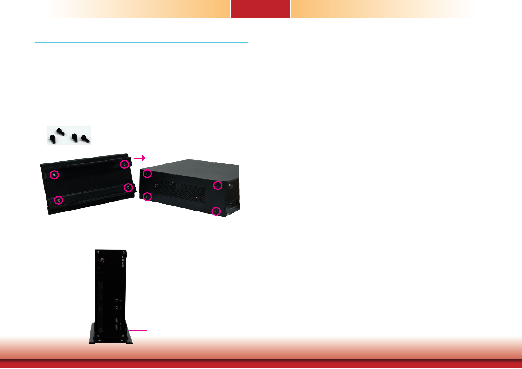
Chapter 6
Chapter 6 - Mounting Options
Desktop Mount
The desktop mount kit includes the following:
• 1 Desktop mounting stand
• Mounting screws
1. The mounting holes are located at the side panel of the system. Fasten the mounting stand
on the side of the system using the mounting screws.
Mounting screws
2. Place the system upright with the stand's support at the bottom.
Desktop mounting stand
Chapter 6 Mounting Options
28
www.d.com
Page 29
Chapter 7
Chapter 7 - BIOS Setup
Overview
The BIOS is a program that takes care of the basic level of communication between the CPU
and peripherals. It contains codes for various advanced features found in this system board.
The BIOS allows you to configure the system and save the configuration in a battery-backed
CMOS so that the data retains even when the power is off. In general, the information stored
in the CMOS RAM of the EEPROM will stay unchanged unless a configuration change has been
made such as a hard drive replaced or a device added.
It is possible that the CMOS battery will fail causing CMOS data loss. If this happens, you need
to install a new CMOS battery and reconfigure the BIOS settings.
Note:
The BIOS is constantly updated to improve the performance of the system board;
therefore the BIOS screens in this chapter may not appear the same as the actual
one. These screens are for reference purpose only.
Default Configuration
Most of the configuration settings are either predefined according to the Load Optimal Defaults
settings which are stored in the BIOS or are automatically detected and configured without
requiring any actions. There are a few settings that you may need to change depending on
your system configuration.
Entering the BIOS Setup Utility
The BIOS Setup Utility can only be operated from the keyboard and all commands are keyboard commands. The commands are available at the right side of each setup screen.
The BIOS Setup Utility does not require an operating system to run. After you power up the
system, the BIOS message appears on the screen and the memory count begins. After the
memory test, the message “Press DEL to run setup” will appear on the screen. If the message
disappears before you respond, restart the system or press the “Reset” button. You may also
restart the system by pressing the <Ctrl> <Alt> and <Del> keys simultaneously.
Legends
Keys Function
Right and Left arrows
Up and Down arrows
<Esc>
<F1>
<F5>
<F6>
<F9>
<F10>
<Enter>
Move the highlight left or right to select a menu.
Move the hightlight up or down between submenu or elds.
Exit the BIOS Setup Utility.
Help
Change values
Change values
Setup Defaults
Save and Exit
Press <Enter> to enter the highlighted submenu.
Scroll Bar
When a scroll bar appears to the right of the setup screen, it indicates that there are more
available fields not shown on the screen. Use the up and down arrow keys to scroll through all
the available fields.
Submenu
When ““ appears on the left of a particular field, it indicates that a submenu which contains
additional options are available for that field. To display the submenu, move the highlight to
that field and press <Enter>.
Chapter 7 BIOS Setup
29
www.d.com
Page 30
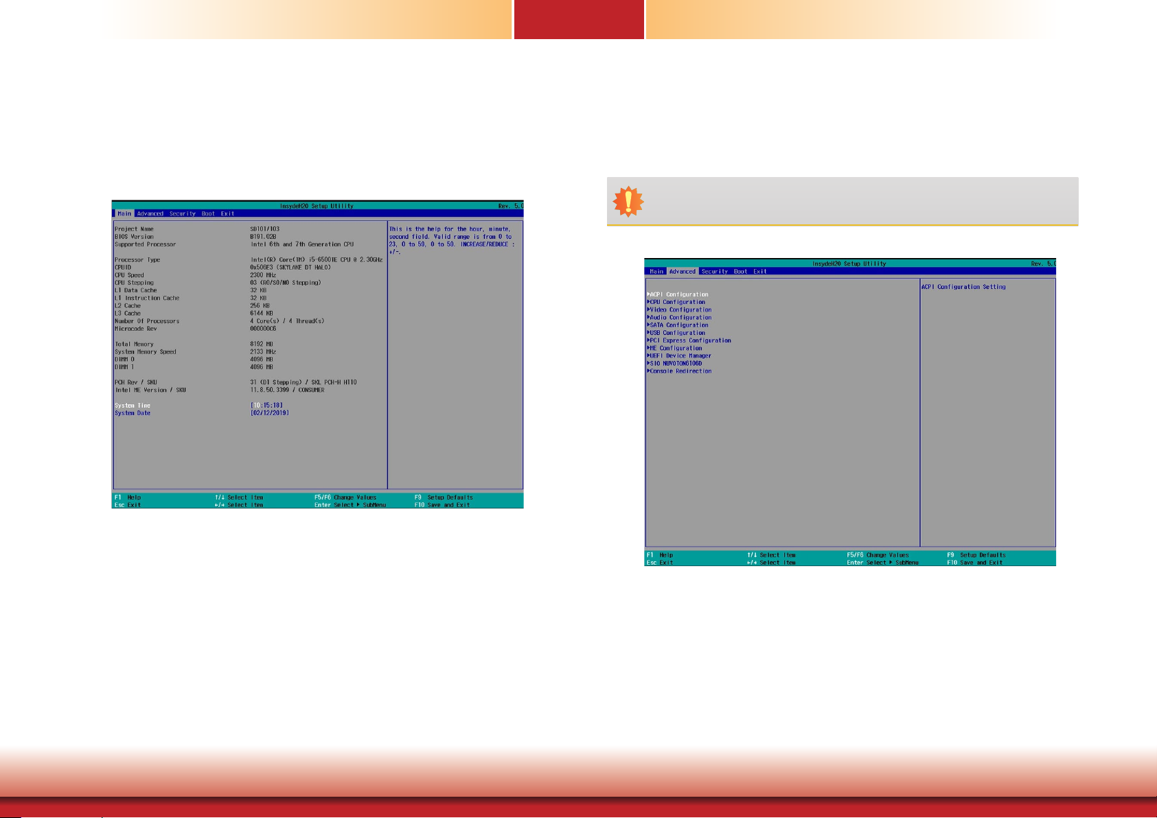
Chapter 7
Insyde BIOS Setup Utility Advanced
Main
The Main menu is the first screen that you will see when you enter the BIOS Setup Utility.
The Advanced menu allows you to configure your system for basic operation. Some entries are
defaults required by the system board, while others, if enabled, will improve the performance
of your system or let you set some features according to your preference.
Important:
Setting incorrect field values may cause the system to malfunction.
System Date
The date format is <month>, <date>, <year>. Month displays the month, from January to December. Date displays the date, from 1 to 31. Year displays the year, from
1980 to 2099.
System Time
The time format is <hour>, <minute>, <second>. The time is based on the 24-hour
military-time clock. For example, 1 p.m. is 13:00:00. Hour displays hours from 00 to
23. Minute displays minutes from 00 to 59. Second displays seconds from 00 to 59.
Chapter 7 BIOS Setup
30
www.d.com
Page 31
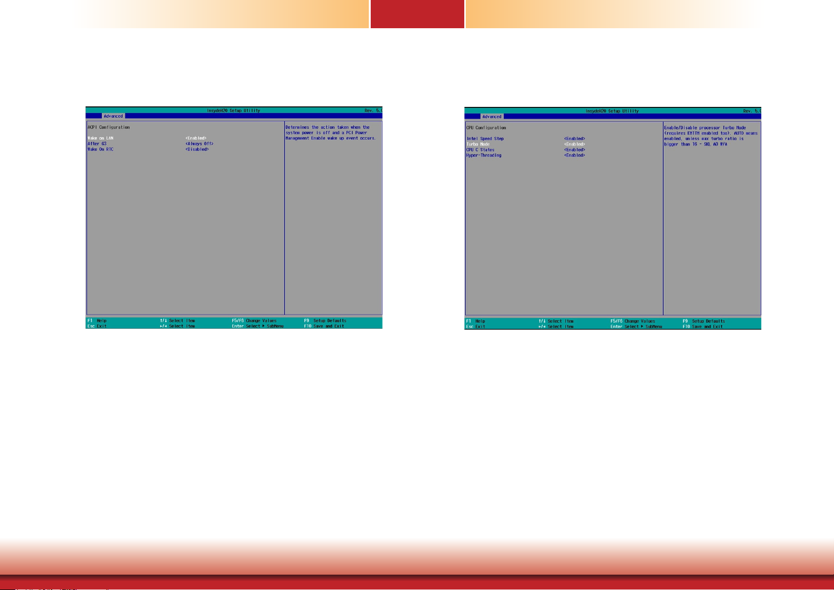
Chapter 7
ACPI Configuration
This section configures system ACPI parameters.
Wake on LAN
This field use to enable or disable the LAN signal to wake up the system.
After G3
This field is to specify which state the system should be in when power is reapplied after a power failure (G3, the mechanical-off, state).
Always On The system is powered on.
Always Off The system is powered off.
CPU Configuration
This section configures the CPU.
Intel® SpeedStep™
Enable or disable the Enhanced Intel SpeedStep® Technology, which helps optimize the
balance between system’s power consumption and performance. After it is enabled in the
BIOS, you can take advantage of its offering by setting power schemes from the operating system’s power options.
Turbo Mode (This option may not be available depending on the model)
Enable or disable processor turbo mode, which allows the processor core to automatically
run faster than the base frequency by taking advantage of thermal and power headroom.
Note this option is not available on the Core™ i3 processor.
Wake on RTC
Automatically power the system on at a particular time every day from the realtime clock battery. Specify the wake up time of the day below: <hour>, <minute>, <second>.
Chapter 7 BIOS Setup
CPU C States
Enable or disable CPU Power Management. It allows the CPU to go to C states when it’s
not 100% utilized.
Hyper-Threading (This option may not be available depending on the model)
Enable Intel® Hyper-Threading Technology (HT) on the processor to improve performance
of operating systems and software that are optimized for hyper-threading technology.
Please check the software specications to determine if enabling HT can be advantageous
to the overall system performance. Note this function is not available with the Intel®
Core™ i5-6500TE, Pentium® G4400TE and Celeron® G3900TE processors.
31
www.d.com
Page 32
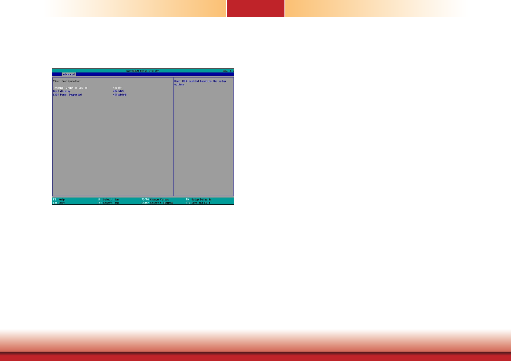
Chapter 7
Video Configuration
This section configures video settings. Note that the configuration options vary depending on
the “Boot type” selected in the “Boot” menu.
Internal Graphics Device
Enable, disable or automatically detect the internal graphics. Note that this option
will be shown only if the “Boot type” is set to “Dual” or “UEFI”.
Boot display
Prioritize device combination for display during system boot with the following
options. Note that this option will be shown only if the “Boot type” is set to “Dual”
or “Legacy”.
LCD+DVI
LCD+DP
DVI+DP
DP+DVI
LVDS Panel Supported (This option may not be available depending on the
model)
Enable this option to configure your LCD panel with the following configurations:
PTN3460 Configuration Select the color depth from the following options:
18bit, 24bit, 36bit, and 48bit.
LCD Panel Type Select the resolution for the LCD panel from the following options: 800x480, 800x600, 1024x768, 1366x768, 1280x1024, and 1920x1080.
Backlight Type
Select the backlight type from the following options: Normal+PWM, Normal+DC,
Invert+PWM, and Invert+DC.
Primary Display
Select the primary display for the system. Note that this option will be shown
only if the “Boot type” is set to “Dual” or “UEFI”. The options are Auto or
IGFX (internal graphics), PEG and PCI. The order of video device initialization
will be as follows:
Auto mode: PEG (PCIe Graphics devices connected to PEG lanes) -> PCIe
graphics devices -> PCI graphics devices -> IGFX (internal graphics)
IGFX: IGFX (internal graphics) -> PEG (PCIe Graphics devices connected to
PEG lanes) -> PCIe graphics devices -> PCI graphics devices
PEG: PEG (PCIe Graphics devices connected to PEG lanes) -> PCIe graphics
devices -> PCI graphics devices -> IGFX (internal graphics)
PCI: PCI graphics devices -> PCIe graphics devices -> PEG (PCIe Graphics devices connected to PEG lanes ) -> IGFX (internal graphics)
Chapter 7 BIOS Setup
32
www.d.com
Page 33
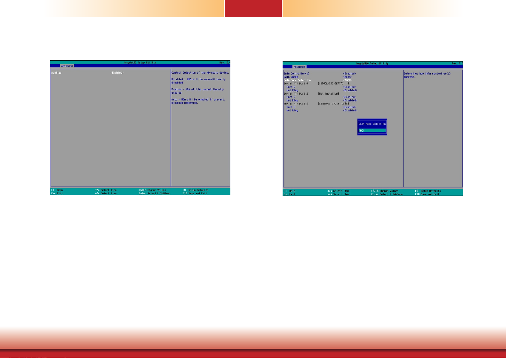
Chapter 7
Audio Configuration
This section configures audio settings.
Azaliza
Control the detection of high-definition audio devices.
Disabled
HDA will be unconditionally disabled.
Enabled
HDA will be unconditionally enabled.
Auto
HDA will be enabled if present, disabled otherwise.
SATA Configuration
This section configures the SATA controllers.
SATA Controller(s)
Enable or disable Serial ATA devices.
SATA Speed
Select Serial ATA device speed from Gen1 (1.5 Gbit/s), Gen2 (3 Gbit/s),
Gen 3 (6 Gbit/s) or auto.
SATA Mode Selection
The mode selection shows how the SATA controller(s) operates.
AHCI Mode
This option allows the Serial ATA devices to use AHCI (Advanced Host Controller Interface).
Chapter 7 BIOS Setup
Serial ATA Port 0, 1, 2, and 3 and Hot Plug
Enable or disable the serial ATA port and its hot plug function.
33
www.d.com
Page 34
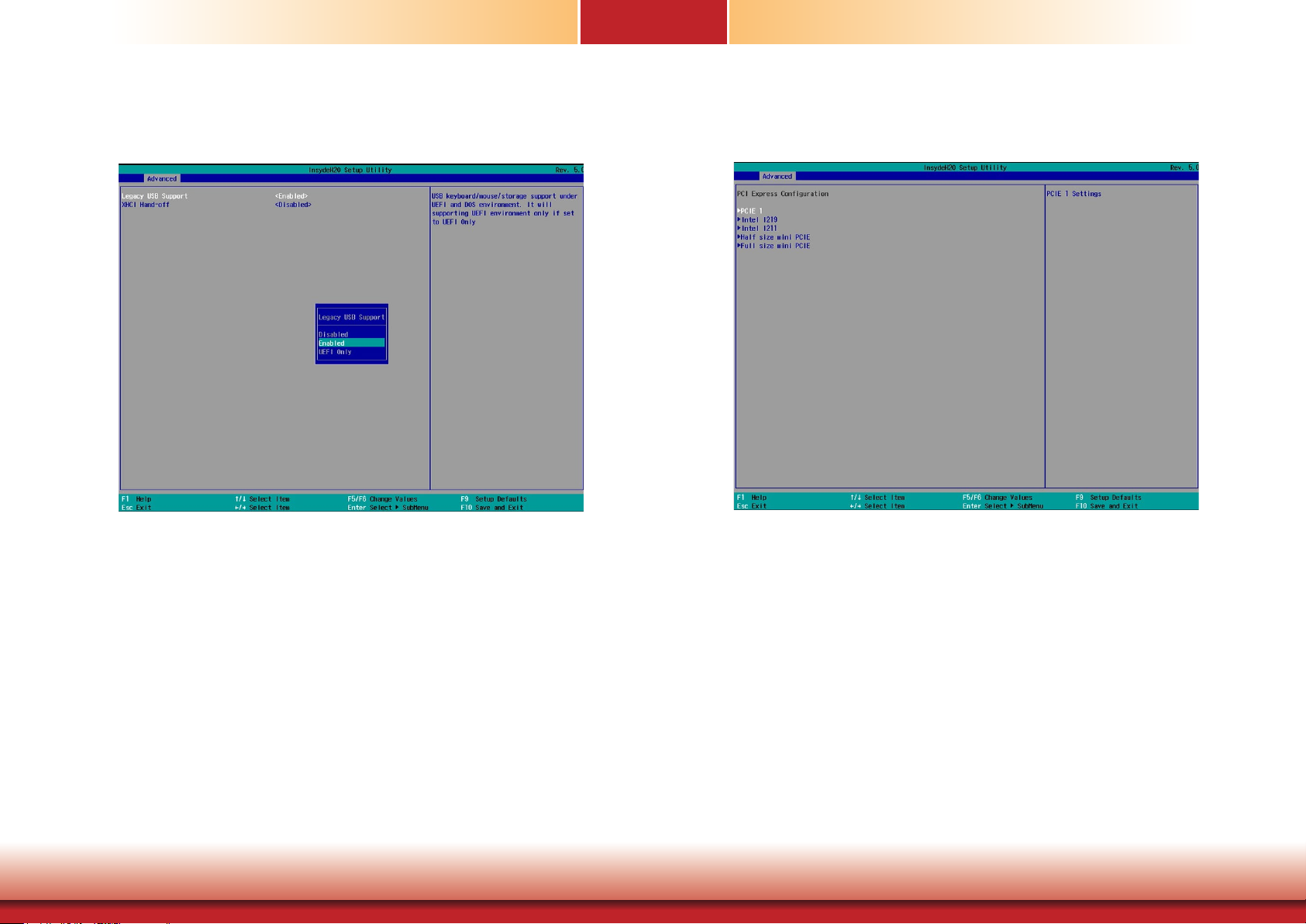
Chapter 7
USB Configuration
This section configures the parameters of the USB devices.
PCI Express Configuration
This section configures the PCI Express root ports.
Legacy USB Support
Disabled
Disable USB keyboard/mouse/storage support.
Enabled
Enable USB keyboard/mouse/storage support.
XHCI Hand-off
Enable this item for operating systems that do not support xHCI Hand-off. The XHCI
ownership change will be claimed by the xHCI driver.
Chapter 7 BIOS Setup
PCI Express Root Port
PCIE 1: PCIE1 expansion slot
Intel I219 Gigabit Ethernet port
Intel I211 Gigabit Ethernet port (Disabled)
Full-size Mini PCIe (may not be available depending on your model)
Half-size Mini PCIe (may not be available depending on your model)
PCI Express Configuration
Select a PCI Express root port and press “Enter” to configure.
Enabled / Disabled
Enable or disable this PCIe slot.
PCIe Speed
Select the PCIe speed: Auto, Gen1 (2.5 GT/s) or Gen2 (5 GT/s).
Hot Plug
Enable or disable hot plug function of the PCIe root port.
34
www.d.com
Page 35
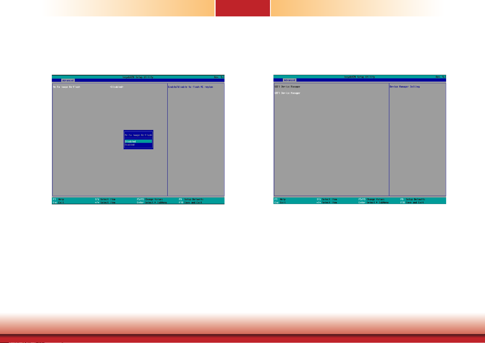
Chapter 7
ME Configuration
This section configures settings of flashing the Intel® Management Engine firmware.
UEFI Device Manager
This Device Manager menu is used to configure UEFI network settings when the “Network
Stack” is enabled in the “Dual” or “UEFI” boot mode or when the “PXE Boot to LAN” is enabled
in the “Legacy” boot mode. Refer to the “Boot” section in this chapter. After this function is
selected, the screen will warn you that you are going to exit the BIOS setup utility.
Me Fw Image Re-Flash
Enable or disable flashing of the Intel® Management Engine firmware.
Chapter 7 BIOS Setup
35
www.d.com
Page 36
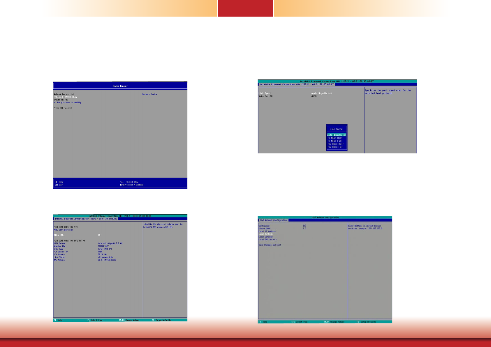
Chapter 7
Network Device List
The “Device Manager” screen is displayed. And if the “Network Stack” or the “PXE Boot
to LAN” option is enabled from the “Boot” menu, the “Network Device List” should
be shown in the “Device list”. Select “Network Device List” to view all of the detected
network devices. For each network device, you can select to view and configure its
settings. In addition, you can select either the IPv4 or IPv6 network settings for UEFI
network configuration.
NIC Configuration Menu
This screen shows hardware information for the Ethernet controllers and configures
their operation.
Blink LEDs
Enter the duration (seconds) to blink the Ethernet’s Speed LED to indicate its presence.
NIC Configuration
This screen configures the Ethernet controller. Select the link speed from the following options: Auto Negotiated, 10Mbps Half, 10Mbps Full, 100Mbps Half, and 100Mbps Full.
IPv4 Network Configuration
This screen configures the IP addressing method (DHCP or static IP). For static IP addressing, configure the following:
Local IP address and subnet mask: Enter the IP address for the network device in the
IPv4 format:
x . x . x . x (x must be a decimal value between 0 and 255).
Local Gateway: Enter the gateway address in the IPv4 format.
Local DNS (Domain Name System) Servers: Enter DNS (Domain Name System) server IP
addresses in the IPv4 format.
Chapter 7 BIOS Setup
36
www.d.com
Page 37
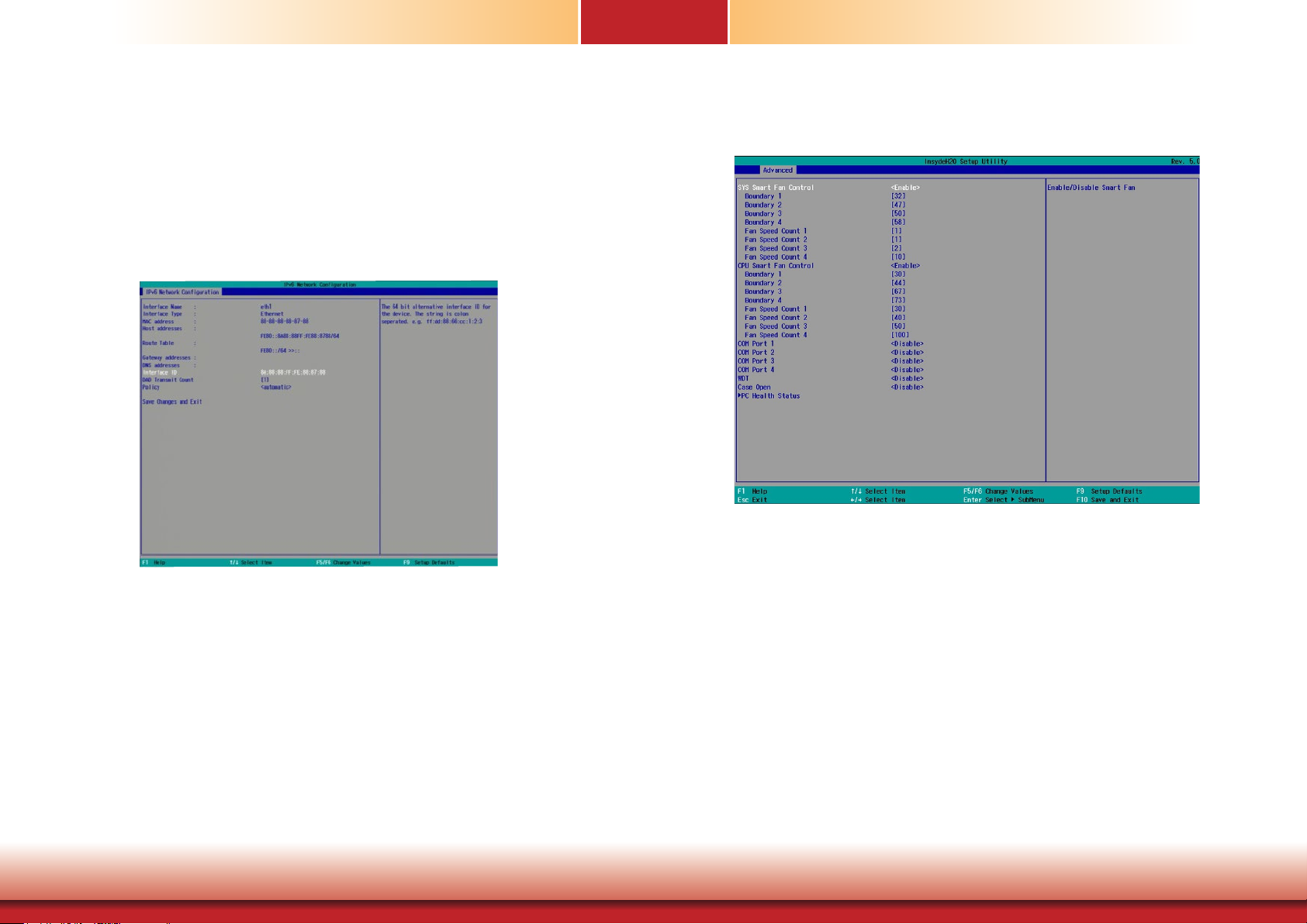
Chapter 7
IPv6 Network Configuration
If you select to use IPv6 network settings, enter the Interface ID (64 bit).
Policy: Select either automatic or manual. And select "Advanced Configuration" to
congure IPv6 network address manually if the manual option is selected.
New IPv6 address: Enter the IP address for the network device in the IPv6 format:
x : x : x : x : x : x : x : x (x can be any hexadecimal value between 0 and FFFF). Place
a space to separate each IP address to enter more than one address.
New Gateway addresses: Enter gateway addresses in the IPv6 format.
New DNS addresses: Enter DNS (Domain Name System) server IP addresses in the
IPv6 format.
SIO NUVOTON6106D
This section configures the system’s super I/O chip parameters.
SYS/CPU Smart Fan Control
Chapter 7 BIOS Setup
Enable or disable the system or CPU smart fan.
Boundary 1 to Boundary 4
Set the boundary temperatures that determine the operation of the fan with different fan speeds accordingly. For example, when the system or the CPU temperature
reaches boundary temperature 1, the system or CPU fan should be turned on and
operate at the designated speed.
The range of the temperature is from 0 to 127oC.
Fan Speed Count 1 to Fan Speed Count 4
Set the fan speed. The range is from 1 (lowest speed)-10 (full speed).
37
www.d.com
Page 38
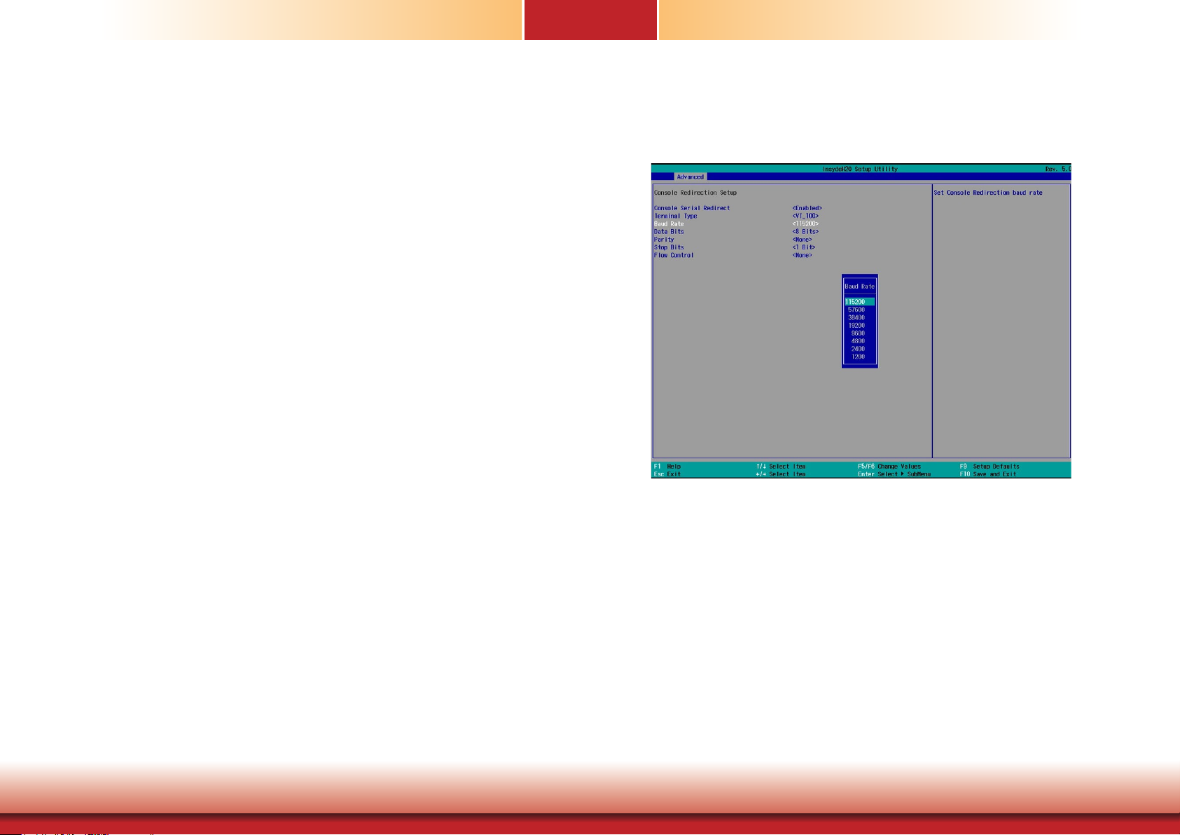
Chapter 7
COM Port 1 to COM Port 4 (These settings may not be available depending
on the model)
Configures the settings of the serial port.
Disable Disable this serial port.
Enable Enable this serial port.
Type
Choose RS232/RS422/RS485 for the serial port type for COM port 1 only.
WDT
Enable or disable the watchdog function. A counter will appear if you select to enable
WDT. Input any value between 1 and 255.
Case Open
Enable or disable the case open function.
Console Redirection
Console redirection lets you monitor and control the system from a remote station by re-directing the host screen output through a serial port.
Chapter 7 BIOS Setup
Console Serial Redirect
Enable or disable the console redirection function. (The default is disabled.) If you
select to enable it, please configure the following parameters for serial communication between the system and a remote station:
Terminal type: VT_100, VT_100+, VT_UTF8, or PC_ANSI.
Baud rate: 115200, 57600, 38400, 19200, 9600, 4800, 2400 or 1200.
Data bits: 8 bits or 7 bits.
Parity: None, Even or Odd.
Stop bits: 1 bit or 2 bits.
Flow control: None, RTS/CTS or XON/XOFF
This is the global setting for all of the designated serial ports for the console redirection function.
38
www.d.com
Page 39
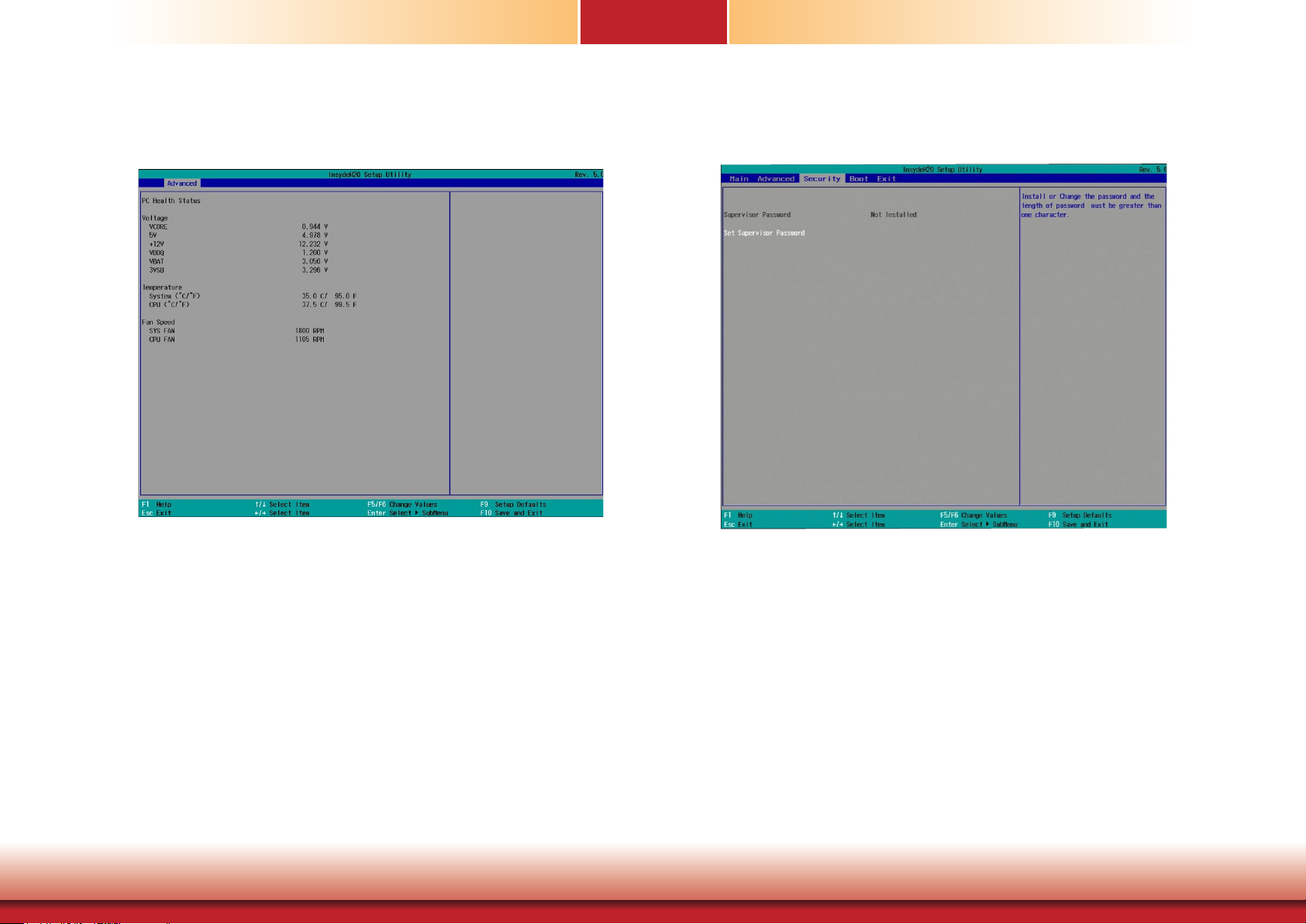
Chapter 7
PC Health Status
This section displays PC health status.
Security
This section configures the security of accessing the BIOS setup utility and system startup.
Chapter 7 BIOS Setup
Set Supervisor Password
Set the administrative password for entering the BIOS setup utility or upon entering
the power-on self-test (POST) process. The length of the password must be greater
than 1 character and less than or equal to 10 characters.
Power-on Password
If you select to set the supervisor password, this option will be shown. Enable or disable prompt for password at boot.
39
www.d.com
Page 40
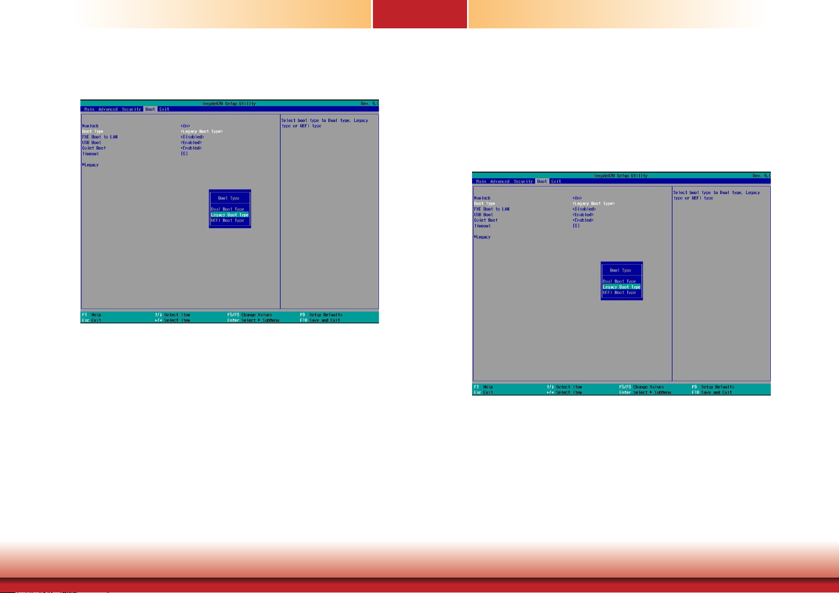
Boot
This section configures boot options.
Chapter 7
Timeout
Enter the number of seconds the BIOS should wait before booting the designated device.
Boot Device Priority
This section configures legacy or EFI boot order or both depending on the “Boot
Type” selected.
NumLock
Select the power-on state for NumLock.
Boot Type
Select the boot type. The options are Dual Boot Type, Legacy Boot Type or UEFI Boot
Type.
Network Stack
This option is shown only when the boot type is set to Dual or UEFI.
Enable or disable UEFI network stack. It supports the operation of these functions or
software: Windows 8 BitLocker Network Unlock, UEFI IPv4/IPv6 PXE and legacy PXE
option ROM.
If this function is enabled, you can then go to “Advanced”>”UEFI Device Manager” to
configure network settings for network connection under the UEFI environment.
PXE Boot Capability (UEFI mode) /PXE Boot to LAN (Legacy mode)
Enable or disable Preboot eXecution Environment (PXE) boot to LAN. In the UEFI or Dual
boot mode, this function can only be enabled if the Network Stack support is enabled.
USB Boot
Enable this function to boot from a USB flash drive.
Quiet Boot
Enable or disable the quiet boot function to configure the screen’s display between
POST messages or the OEM logo at bootup. Select Disabled to display the POST messages and select Enabled to display the OEM logo.
Chapter 7 BIOS Setup
EFI Boot Menu
Use + and - keys to rearrange the priority list for boot devices.
Legacy Boot Menu
Normal
For this option, determine the boot order for the devices within each category. Use
the + and - key to arrange the priority of the boot type devices in the list. The first
device in the list has the highest boot priority.
Advance
For this option, determine the boot order for all bootable devices. Use + and - keys
to arrange the priority of the detected boot devices in the list. The first device in the
list has the highest boot priority.
40
www.d.com
Page 41
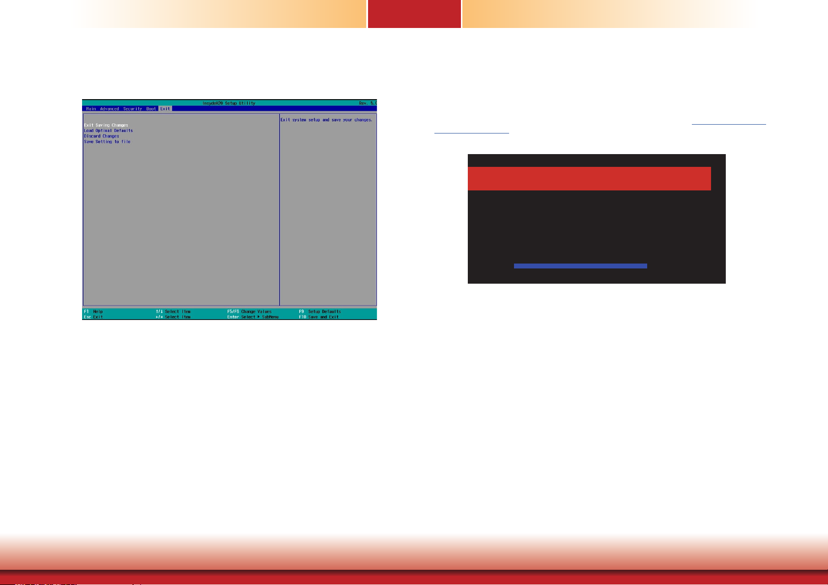
Chapter 7
Exit
This section configures the parameters for exiting the BIOS menu.
Exit Saving Changes
Select this field and press <Enter> to exit BIOS setup and save your changes.
Updating the BIOS
To update the BIOS,To update the BIOS, you will need the new BIOS file and a flash utility. Please contact technical support or your sales representative for latest BIOS file and the
firmware update utility.
For instructions on how to update BIOS with the flash utility, please see https://www.dfi.com/
Knowledge/Video/31 from the Knowledge Base of the DFI website.
Read le successfully. (path= “platform.ini”)
R
Insyde H20FFT (Flash Firmware Tool) Version (SEG) 100.00.08.10
Copyright(c) 2012 - 2016, Insyde Software Corp. All Rights Reserved.
Initializing
Current BIOS Model name: SD101/103
New BIOS Model name: SD101/103
Current BIOS version: B191.02B
New BIOS version: B191.03B
Updating Block at FFFFF000h
0% 25% 50% 75% 100%
100%
C:\SD100/103>_
Information
Please do not remove the AC power
Load Optimal Defaults
Select this field and press <Enter> to load the optimal defaults.
Discard Changes
Select this field and press <Enter>to exit the BIOS setup without saving your changes.
Save Setting to file
Select this option to save BIOS configuration settings to a USB drive. The operation will
fail if there aren’t any USB devices detected on the system. The saved configuration
will have the DSF file extension and can be used for restoration.
Restore Setting from file
Select this option to restore BIOS configuration settings from a USB drive. Note that
this option will not be available if there aren’t any USB devices detected on the system.
Chapter 7 BIOS Setup
41
www.d.com
Page 42
Chapter 7
Notice: BIOS SPI ROM
1. The Intel® Management Engine has already been integrated into this system board. Due to
the safety concerns, the BIOS (SPI ROM) chip cannot be removed from this system board
and used on another system board of the same model.
2. The BIOS (SPI ROM) on this system board must be the original equipment from the factory
and cannot be used to replace one which has been utilized on other system boards.
3. If you do not follow the methods above, the Intel® Management Engine will not be updated
and will cease to be effective.
Note:
a. You can take advantage of flash tools to update the default configuration of the
BIOS (SPI ROM) to the latest version anytime.
b. When the BIOS IC needs to be replaced, you have to populate it properly onto the
system board after the EEPROM programmer has been burned and follow the
technical person's instructions to confirm that the MAC address should be burned
or not.
Chapter 7 BIOS Setup
42
www.d.com
Page 43
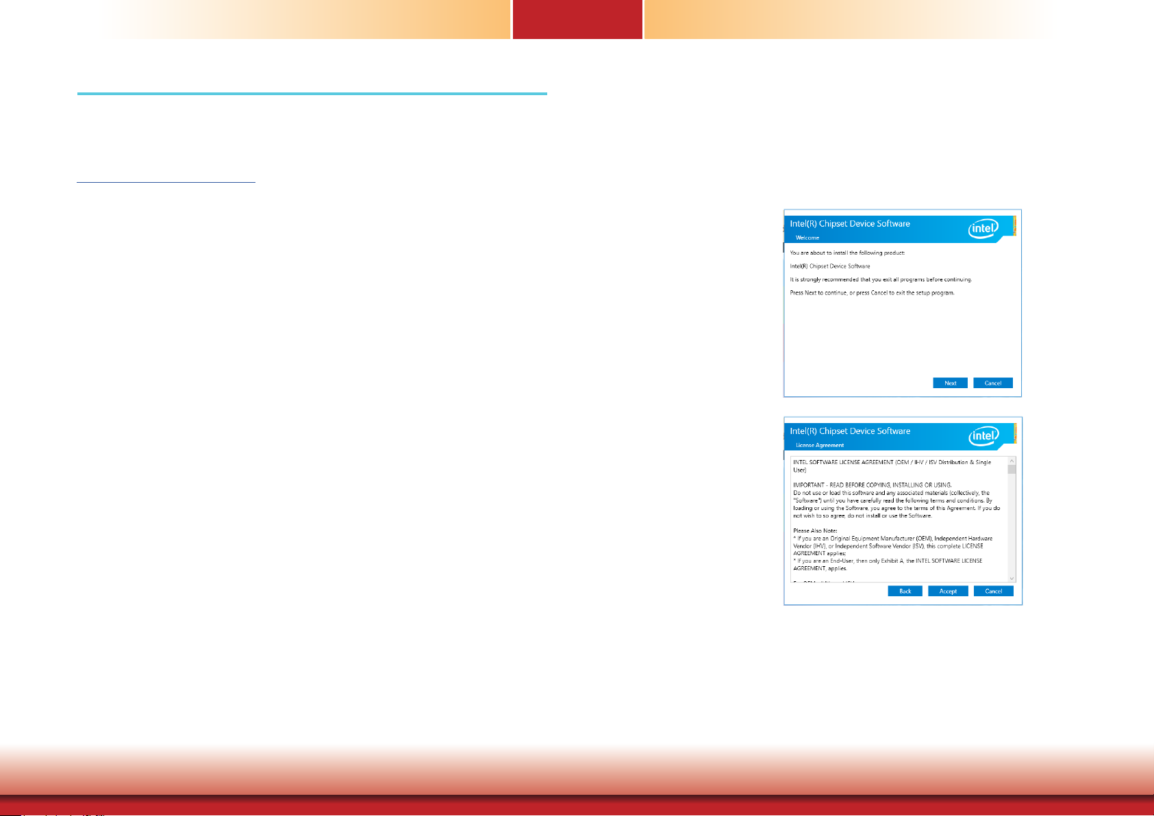
Chapter 8 - Supported Software
Chapter 8
Intel Chipset Device Software
The system requires you to install drivers for some devices to operate properly. Your product
package may include a CD that contain drivers. You can also download the latest drivers from
the DFI Download Center:
http://www.dfi.com/DownloadCenter
Once you are in the Download Center page, select your product or type the model name and
click "Search" to nd product-related resources such as documentation and drivers.
Drivers are available for the following devices in Windows 10:
• Intel® Chipset Device Software
• Intel® Graphics Driver
• Intel® LAN Driver
• Intel® ME Driver
• Audio Driver
• Intel® Serial IO Driver
The Intel Chipset Device Software is used for updating Windows® INF files so that the Intel
chipset can be recognized and configured properly in the system.
Please use the following procedure to install the “Intel Chipset Device Software”.
1. Setup is ready to install
the utility. Click “Next” to
continue.
2. Read the license agreement
and then click “Yes”.
Chapter 8 Supported Software
43
www.d.com
Page 44
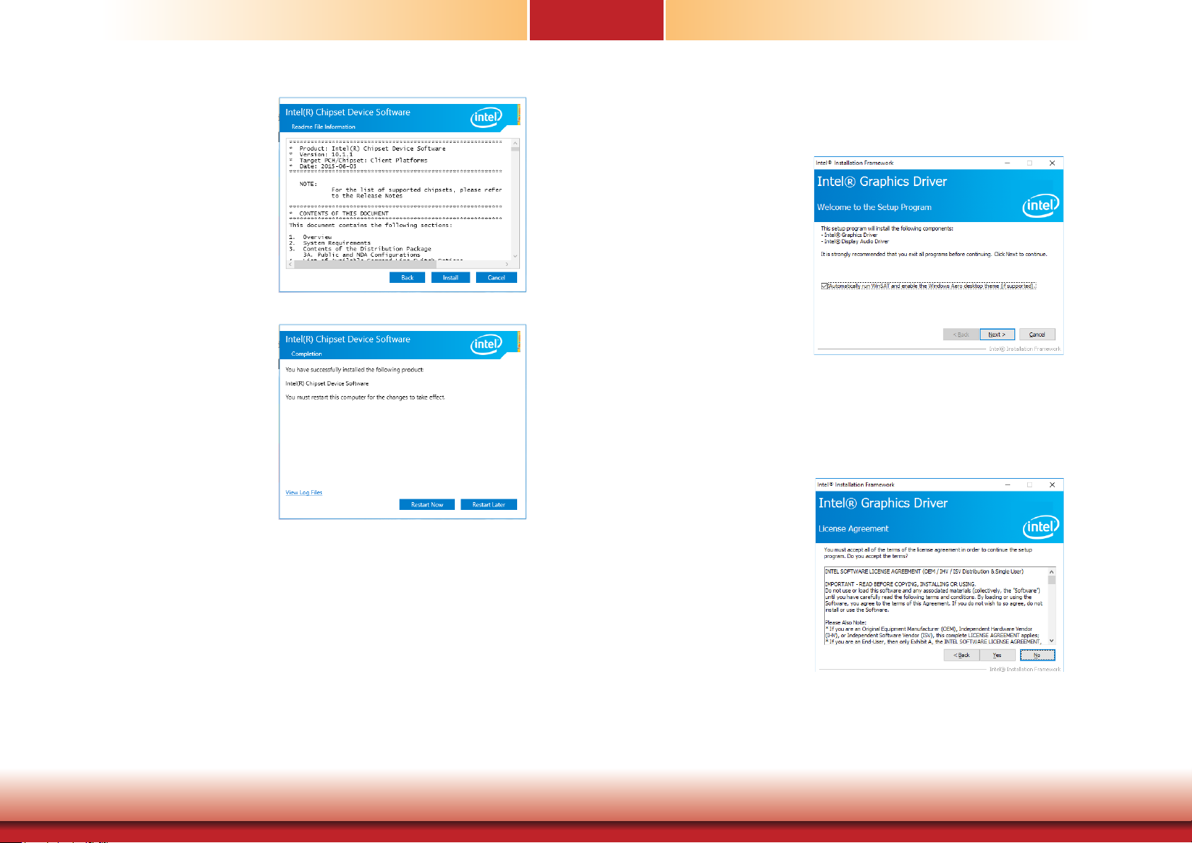
Chapter 8
3. Go through the readme document for more installation tips
and then click “Next”.
4. Click “Finish” to exit setup.
Intel Graphics Driver
Please use the following procedure to install the Intel Graphics Driver.
1. Setup is now ready to install
the graphics driver. Click
“Next” to continue.
By default, the “Automatically run WinSAT and enable the Windows Aero desktop
theme” is enabled. With this enabled, after the graphics driver is installed and the
system is rebooted, the screen will turn blank for 1 to 2 minutes (while WinSAT is
running) before the Windows 7/Windows 8.1/Windows 10 desktop appears. The
“blank screen” period is the time Windows is testing the graphics performance.
2. Read the license agreement
and then click “Yes”.
Chapter 8 Supported Software
44
www.d.com
Page 45
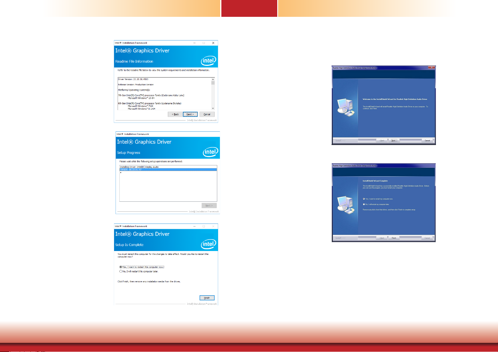
Chapter 8
3. Go through the readme
document for system requirements and installation
tips and then click “Next”.
4. Setup is now installing
the driver. Click “Next” to
continue.
Audio Drivers
Please use the following procedure to install audio drivers.
1. Setup is ready to install
the driver. Click “Next” to
continue.
2. Click “Yes, I want to restart
my computer now” and
then click “Finish”.
Restarting the system will
allow the new software
installation to take effect.
5. Click “Yes, I want to restart
this computer now” and
then click “Finish”.
Restarting the system will
allow the new software
installation to take effect.
Chapter 8 Supported Software
45
www.d.com
Page 46
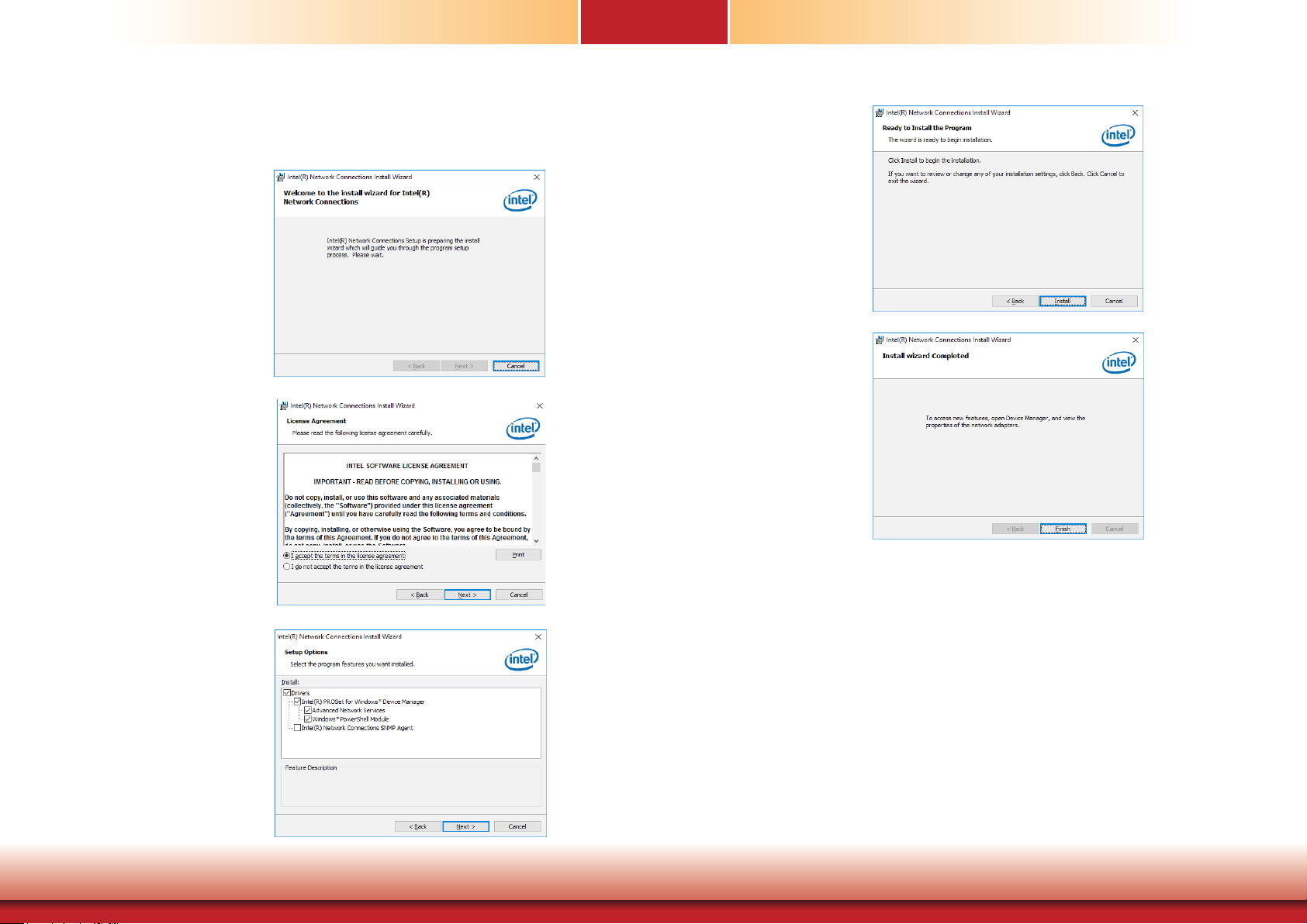
Chapter 8
Intel LAN Driver
Please use the following procedure to install the Intel LAN Driver.
1. Setup is ready to install
the driver. Click “Next” to
continue.
2. Read and License Agreement and click “I accept
the terms in the license
agreement” if you agree
the terms in the agreement, and then click “Next”.
4. Click “Install” to begin the
installation.
5. After the installation is
complete, click “Finish” to
exit setup.
3. Select the program features
you want to install and
then click “Next”.
Chapter 8 Supported Software
46
www.d.com
Page 47
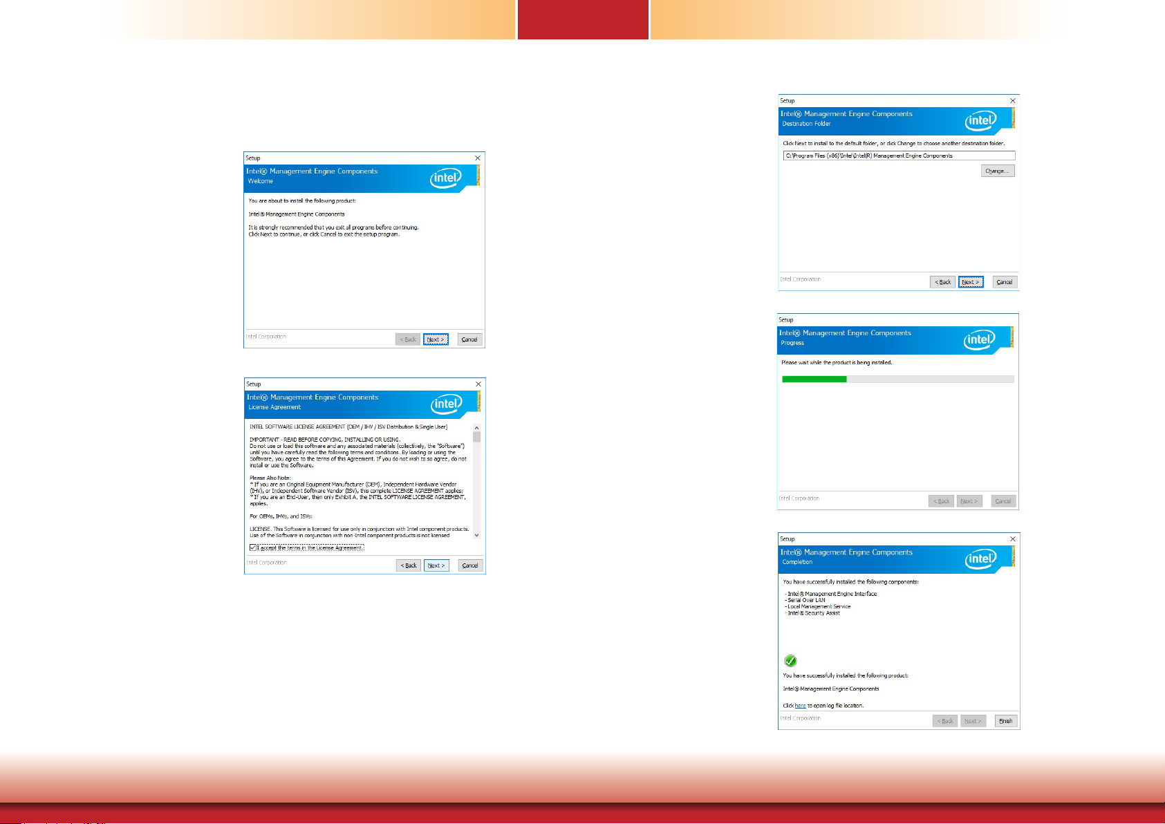
Chapter 8
Intel Management Engine Drivers
Please use the following procedure to install the Intel Management Engine Driver.
1. Setup is ready to install
the driver. Click “Next” to
continue.
2. Read and License Agreement and click “I accept
the terms in the license
agreement” if you agree
with the terms in the
agreement, and then click
“Next”.
3. Setup is currently installing
the driver. After the installation is complete, click
“Next”.
4. Please wait while the product is being installed.
Chapter 8 Supported Software
5. After the installation is
complete, click “Finish” to
exit setup.
47
www.d.com
Page 48
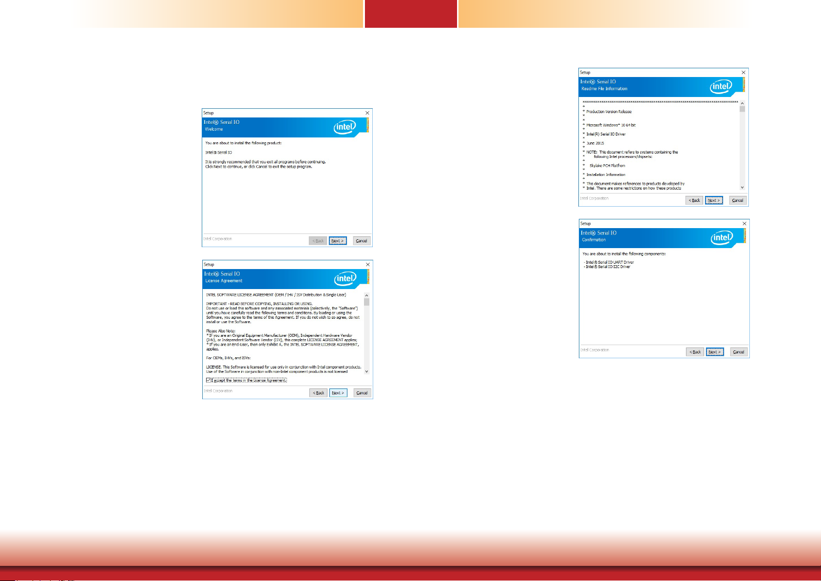
Chapter 8
IO Driver
Please use the following procedure to install the Intel Serial IO Driver.
1. Setup is ready to install the driver.
Click “Next” to continue.
2. Read the license agreement carefully.
Click “I accept the terms in the
License Agreement” if you agree with
the terms in the agreement and then
click “Next”.
3. Read the file information and then
click “Next”.
4. Setup is ready to install the driver.
Click “Next” to begin the installation.
Chapter 8 Supported Software
48
www.d.com
Page 49
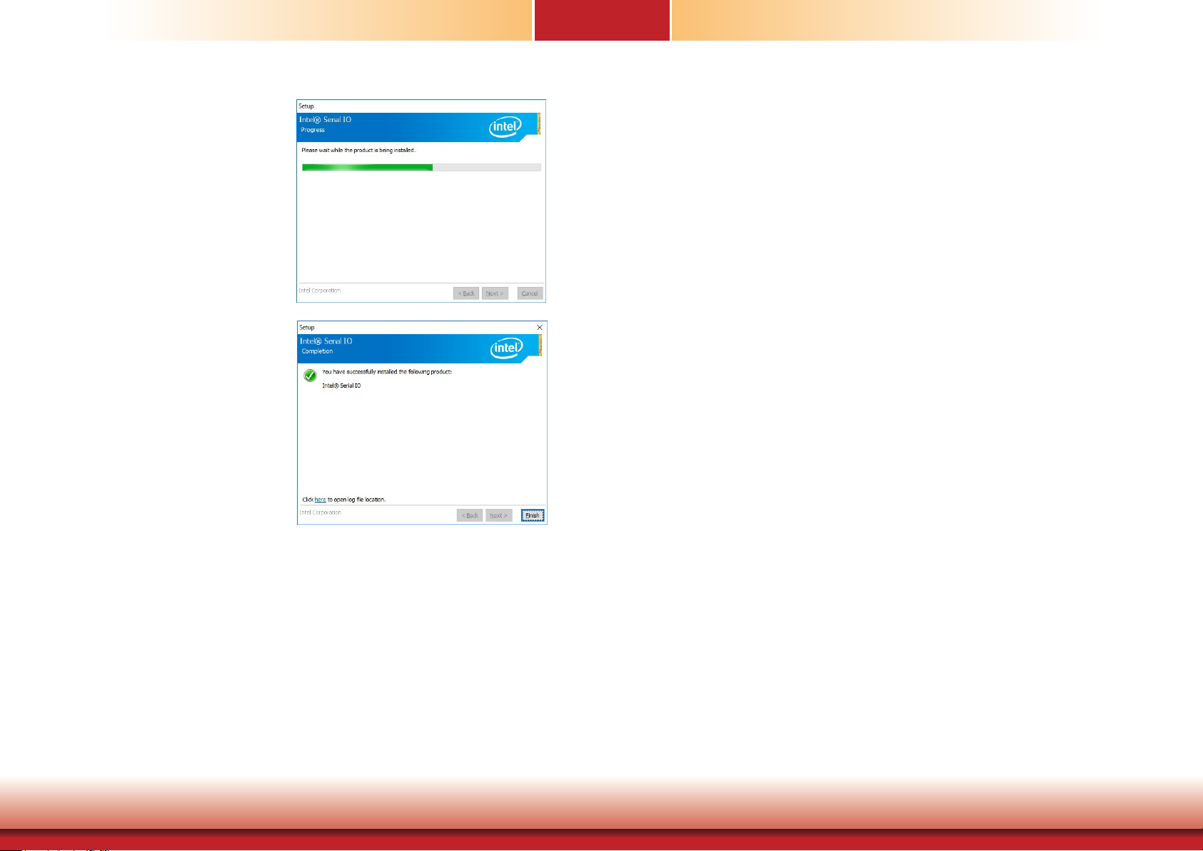
5. Setup is now installing the
driver.
6. Click “Finish” to exit setup.
Chapter 8
Chapter 8 Supported Software
49
www.d.com
 Loading...