

Page 1
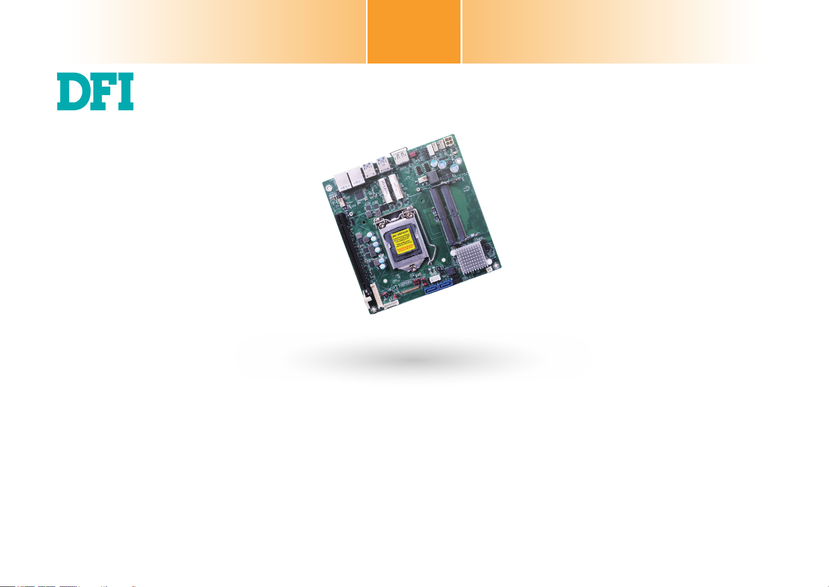
SD106
Mini-ITX Industrial Motherboard
User’s Manual
A40300937
1
Page 2

Copyright
This publication contains information that is protected by copyright. No part of it may be reproduced in any form or by any means or used to make any transformation/adaptation without
the prior written permission from the copyright holders.
This publication is provided for informational purposes only. The manufacturer makes no
representations or warranties with respect to the contents or use of this manual and specifically disclaims any express or implied warranties of merchantability or fitness for any particular
purpose. The user will assume the entire risk of the use or the results of the use of this document. Further, the manufacturer reserves the right to revise this publication and make changes
to its contents at any time, without obligation to notify any person or entity of such revisions
or changes.
Changes after the publication’s first release will be based on the product’s revision. The website
will always provide the most updated information.
© 2019. All Rights Reserved.
Trademarks
Product names or trademarks appearing in this manual are for identification purpose only and
are the properties of the respective owners.
FCC and DOC Statement on Class B
This equipment has been tested and found to comply with the limits for a Class B digital
device, pursuant to Part 15 of the FCC rules. These limits are designed to provide reasonable protection against harmful interference when the equipment is operated in a residential
installation. This equipment generates, uses and can radiate radio frequency energy and, if not
installed and used in accordance with the instruction manual, may cause harmful interference
to radio communications. However, there is no guarantee that interference will not occur in a
particular installation. If this equipment does cause harmful interference to radio or television
reception, which can be determined by turning the equipment off and on, the user is encouraged to try to correct the interference by one or more of the following measures:
• Reorient or relocate the receiving antenna.
• Increase the separation between the equipment and the receiver.
• Connect the equipment into an outlet on a circuit different from that to which the receiver
is connected.
• Consult the dealer or an experienced radio TV technician for help.
Notice:
1. The changes or modifications not expressly approved by the party responsible for compliance could void the user’s authority to operate the equipment.
2. Shielded interface cables must be used in order to comply with the emission limits.
2
Page 3

Table of Contents
Copyright .............................................................................................................2
Trademarks ........................................................................................................ 2
FCC and DOC Statement on Class B .....................................................2
Warranty ..............................................................................................................4
Static Electricity Precautions ......................................................................4
Safety Measures ..............................................................................................4
About the Package .........................................................................................5
Optional Items..................................................................................................5
Before Using the System Board ...............................................................5
Chapter 1 - Introduction .............................................................................6
Specifications ................................................................................................6
Features ..........................................................................................................7
Chapter 2 - Hardware Installation ................................................ 8
Board Layout .................................................................................................8
System LED ...................................................................................................8
System Memory ............................................................................................9
Installing the DIMM Module ..........................................................................9
CPU ................................................................................................................ 10
Installing the CPU ....................................................................................... 11
Installing the Fan and Heat Sink..................................................................13
Jumper Settings ......................................................................................... 14
Clear CMOS Data ........................................................................................ 14
Auto Power-on Select ..................................................................................14
LVDS Panel Power Select ............................................................................ 15
PCIE1 Signal Select..................................................................................... 15
LCD/Inverter Power Select ..........................................................................16
LVDS Backlight Power Select .......................................................................16
Mini PCIe 1 Signal Select ............................................................................ 17
Mini PCIe 2 Signal Select ............................................................................ 17
eDP Panel Power Select .............................................................................. 18
eDP Inverter Power Select ..........................................................................18
eDP Backlight Power Select ......................................................................... 19
Rear Panel I/O Ports .................................................................................20
Graphics Interfaces ..................................................................................... 20
RJ45 LAN Ports ........................................................................................... 21
USB Ports ................................................................................................... 21
I/O Connectors ........................................................................................... 22
SATA (Serial ATA) Connectors ...................................................................... 22
SATA (Serial ATA) Power Connectors ............................................................ 22
Digital I/O .................................................................................................. 23
Cooling Fan Connectors...............................................................................23
Chassis Intrusion Connector ........................................................................ 24
Front Panel Connector ................................................................................ 24
Expansion Slots .......................................................................................... 25
Standby Power LED .................................................................................... 26
LVDS Panel .................................................................................................27
SMBus Connector ....................................................................................... 28
Speaker Connector ..................................................................................... 28
COM (Serial) Ports ...................................................................................... 29
Front Audio Connector ................................................................................ 29
Power ATX Mode ........................................................................................ 30
15~36V DC-in ........................................................................................... 30
EDP Connector ........................................................................................... 31
Battery ....................................................................................................... 32
Chapter 3 - BIOS Setup ............................................................... 33
Overview....................................................................................................... 33
Main ............................................................................................................... 34
Advanced ...................................................................................................... 34
ACPI Configuration ..................................................................................... 35
CPU Configuration.......................................................................................36
Video Configuration .................................................................................... 36
Audio Configuration .................................................................................... 37
SATA Configuration ..................................................................................... 38
USB Configuration....................................................................................... 38
PCI Express Configuration ........................................................................... 39
ME Configuration ........................................................................................ 40
Active Management Technology Support ...................................................... 40
MEBX Configuration .................................................................................... 41
Debug Configuration ................................................................................... 41
Device Manager .......................................................................................... 42
SIO NUVOTON6106D .................................................................................. 43
Console Redirection .................................................................................... 45
Security ......................................................................................................... 47
Boot ............................................................................................................... 47
Exit ................................................................................................................. 48
Updating the BIOS .................................................................................... 49
Notice: BIOS SPI ROM ............................................................................. 49
Chapter 4 - Supported Software ................................................ 50
Chapter 5 - RAID .......................................................................... 67
Chapter 6 - Intel AMT Settings ................................................. 71
3
Page 4

Warranty
1. Warranty does not cover damages or failures that arised from misuse of the product, inability to use the product, unauthorized replacement or alteration of components and product specifications.
2. The warranty is void if the product has been subjected to physical abuse, improper installation, modification, accidents or unauthorized repair of the product.
3. Unless otherwise instructed in this user’s manual, the user may not, under any circumstances, attempt to perform service, adjustments or repairs on the product, whether in or
out of warranty. It must be returned to the purchase point, factory or authorized service
agency for all such work.
Static Electricity Precautions
It is quite easy to inadvertently damage your PC, system board, components or devices even
before installing them in your system unit. Static electrical discharge can damage computer
components without causing any signs of physical damage. You must take extra care in handling them to ensure against electrostatic build-up.
1. To prevent electrostatic build-up, leave the system board in its anti-static bag until you are
ready to install it.
2. Wear an antistatic wrist strap.
3. Do all preparation work on a static-free surface.
4. We will not be liable for any indirect, special, incidental or consequencial damages to the
product that has been modified or altered.
4. Hold the device only by its edges. Be careful not to touch any of the components, contacts
or connections.
5. Avoid touching the pins or contacts on all modules and connectors. Hold modules or connectors by their ends.
Important:
Electrostatic discharge (ESD) can damage your processor, disk drive and other components. Perform the upgrade instruction procedures described at an ESD workstation only. If such a station is not available, you can provide some ESD protection by
wearing an antistatic wrist strap and attaching it to a metal part of the system chassis. If a wrist strap is unavailable, establish and maintain contact with the system
chassis throughout any procedures requiring ESD protection.
Safety Measures
To avoid damage to the system:
• Use the correct AC input voltage range.
To reduce the risk of electric shock:
• Unplug the power cord before removing the system chassis cover for installation or servicing. After installation or servicing, cover the system chassis before plugging the power
cord.
4
Page 5

About the Package
The package contains the following items. If any of these items are missing or damaged,
please contact your dealer or sales representative for assistance.
• 1 SD106-Q170 motherboard
• 1 Battery Addendum
The board and accessories in the package may not come similar to the information listed
above. This may differ in accordance to the sales region or models in which it was sold. For
more information about the standard package in your region, please contact your dealer or
sales representative.
Before Using the System Board
Before using the system board, prepare basic system components.
If you are installing the system board in a new system, you will need at least the following
internal components.
• A CPU
• Memory module
• Storage devices such as hard disk drive, etc.
You will also need external system peripherals you intend to use which will normally include at
least a keyboard, a mouse and a video display monitor.
5
Page 6

Chapter 1 - Introduction
Specifications
Chapter 1
SYSTEM Processor 6th Generation Intel® CoreTM Processors, LGA 1151 Socket
Chipset Intel
Memory Two 260-pin SODIMM up to 32GB
BIOS
GRAPHICS Controller Intel
Feature
Display 1 x eDP eDP: resolution up to 4096x2304 @ 60Hz
Triple
Displays
EXPANSION Interface 1 x Full-size Mini PCIe (USB/PCIe/mSATA, mSATA by default)
AUDIO
ETHERNET Controller 1 x Intel® I211AT PCIe (10/100/1000Mbps)
REAR I/O Ethernet
Audio
Codec
USB 4 x USB 3.0
Display 1 x DP++
®
Intel
Pentium® G4400, Dual Core, 3M Cache, 3.3GHz, 47W
®
Q170 Chipset
Dual Channel DDR4 1866/2133MHz
Insyde SPI 128Mbit
®
HD Gen 9 Graphics
OpenGL 5.0, DirectX 12, OpenCL 2.1
HW Decode: AVC/H.264, MPEG2, VC1/WMV9, JPEG/MJPEG, HEVC/H265, VP8, VP9
HW Encode: MPEG2, AVC/H264, JPEG, HEVC/H265, VP8, VP9
1 x LVDS LVDS: resolution up to 1920x1200 @ 60Hz
1 x DP++ DP++: resolution up to 4096x2304 @ 60Hz
eDP + LVDS + DP++
1 x Half-size Mini PCIe (Mini PCIe by default)
1 x PCIe x16
Realtek ALC888S-VD2-GR
®
I219LM PCIe with iAMT 11.0 (10/100/1000Mbps) (only Core i7/i5 supports iAMT)
1 x Intel
2 x GbE (RJ-45)
INTERNAL I/O Serial 2 x RS-232 (2.54mm pitch)
USB 4 x USB 2.0 (2.00mm pitch)
Display 1 x eDP
Audio 1 x Front Audio (Line-out/Mic-in)
SATA 2 x SATA 3.0 (up to 6Gb/s)
DIO 1 x 4-bit DIO
SMBus 1 x SMBus
WATCHDOG
TIMER
SECURITY TPM TPM2.0
POWER Type 15~36V DC
OS SUPPORT Windows 7
ENVIRONMENT Temperature Operating: 0 to 60°C
MECHANICAL Dimensions Mini-ITX Form Factor
Output &
Interval
Connector Vertical Type Connector (4-pin)
RTC Battery CR2032 Coin Cell
Humidity Operating: 5 to 90% RH
1 x LVDS LCD Panel Connector
1 x Speaker (3W amplifier)
RAID 0/1
System Reset, Programmable via Software from 1 to 255 Seconds
Windows 8.1
Windows 10
Storage: -40 to 85°C
Storage: 5 to 90% RH
170mm (6.7") x 170mm (6.7")
6
Chapter 1 Introduction www.d.com
Page 7

Chapter 1
Features
• Watchdog Timer
The Watchdog Timer function allows your application to regularly “clear” the system at the set
time interval. If the system hangs or fails to function, it will reset at the set time interval so
that your system will continue to operate.
• DDR4
DDR4 delivers increased system bandwidth and improves performance. The advantages of
DDR4 provide an extended battery life and improve the performance at a lower power than
DDR3/DDR2.
• Graphics
The integrated Intel® HD graphics engine delivers an excellent blend of graphics performance
and features to meet business needs. It provides excellent video and 3D graphics with outstanding graphics responsiveness. These enhancements deliver the performance and compatibility needed for today’s and tomorrow’s business applications. Supports 1 eDP, 1 LVDS and 1
DP++ interfaces for display outputs.
• PCI Express
PCI Express is a high bandwidth I/O infrastructure that possesses the ability to scale speeds
by forming multiple lanes. The PCI Express architecture also supports high performance graphics infrastructure by enhancing the capability of a PCIe x16 Gen 3 at 16GB/s bandwidth.
• Serial ATA
Serial ATA is a storage interface that is compliant with SATA 1.0a specification. With speed of
up to 6Gb/s (SATA 3.0), it improves hard drive performance faster than the standard parallel
ATA whose data transfer rate is 100MB/s.
• Gigabit LAN
Intel® I211AT PCIe Gigabit Ethernet and Intel® I219LM PCIe with iAMT11.0 Gigabit Ethernet
Phy controllers support up to 1Gbps data transmission.
• Audio
The Realtek ALC888S-VD2-GR audio codec provides 5.1-channel High Definition audio output.
• Wake-On-LAN
This feature allows the network to remotely wake up a Soft Power Down (Soft-Off) PC. It is
supported via the onboard LAN port or via a PCIe LAN card that uses the PCIe PME (Power
Management Event) signal. However, if your system is in the Suspend mode, you can poweron the system only through an IRQ or DMA interrupt.
• Wake-On-USB
This function allows you to use a USB keyboard or USB mouse to wake up a system from the
S3 (STR - Suspend To RAM) state.
• RTC Timer
The RTC installed on the system board allows your system to automatically power-on on the
set date and time.
• ACPI STR
The system board is designed to meet the ACPI (Advanced Configuration and Power Interface)
specification. ACPI has energy saving features that enables PCs to implement Power Management and Plug-and-Play with operating systems that support OS Direct Power Management.
ACPI when enabled in the Power Management Setup will allow you to use the Suspend to RAM
function.
With the Suspend to RAM function enabled, you can power-off the system at once by pressing
the power button or selecting “Standby” when you shut down Windows® without having to go
through the sometimes tiresome process of closing files, applications and operating system.
This is because the system is capable of storing all programs and data files during the entire
operating session into RAM (Random Access Memory) when it powers-off. The operating session will resume exactly where you left off the next time you power-on the system.
• Power Failure Recovery
When power returns after an AC power failure, you may choose to either power-on the system
manually or let the system power-on automatically.
• USB
The system board supports the new USB 3.0. It is capable of running at a maximum transmission speed of up to 5 Gbit/s (625 MB/s) and is faster than USB 2.0 (480 Mbit/s, or 60 MB/s)
and USB 1.1 (12Mb/s). USB 3.0 reduces the time required for data transmission, reduces
power consumption, and is backward compatible with USB 2.0. It is a marked improvement in
device transfer speeds between your computer and a wide range of simultaneously accessible
external Plug and Play peripherals.
Chapter 1 Introduction www.d.comChapter 1 Introduction
7
Page 8
Chapter 2 - Hardware Installation
JP5JP3SMBus
USB 2.0 (7/8)
USB 2.0 (5/6)
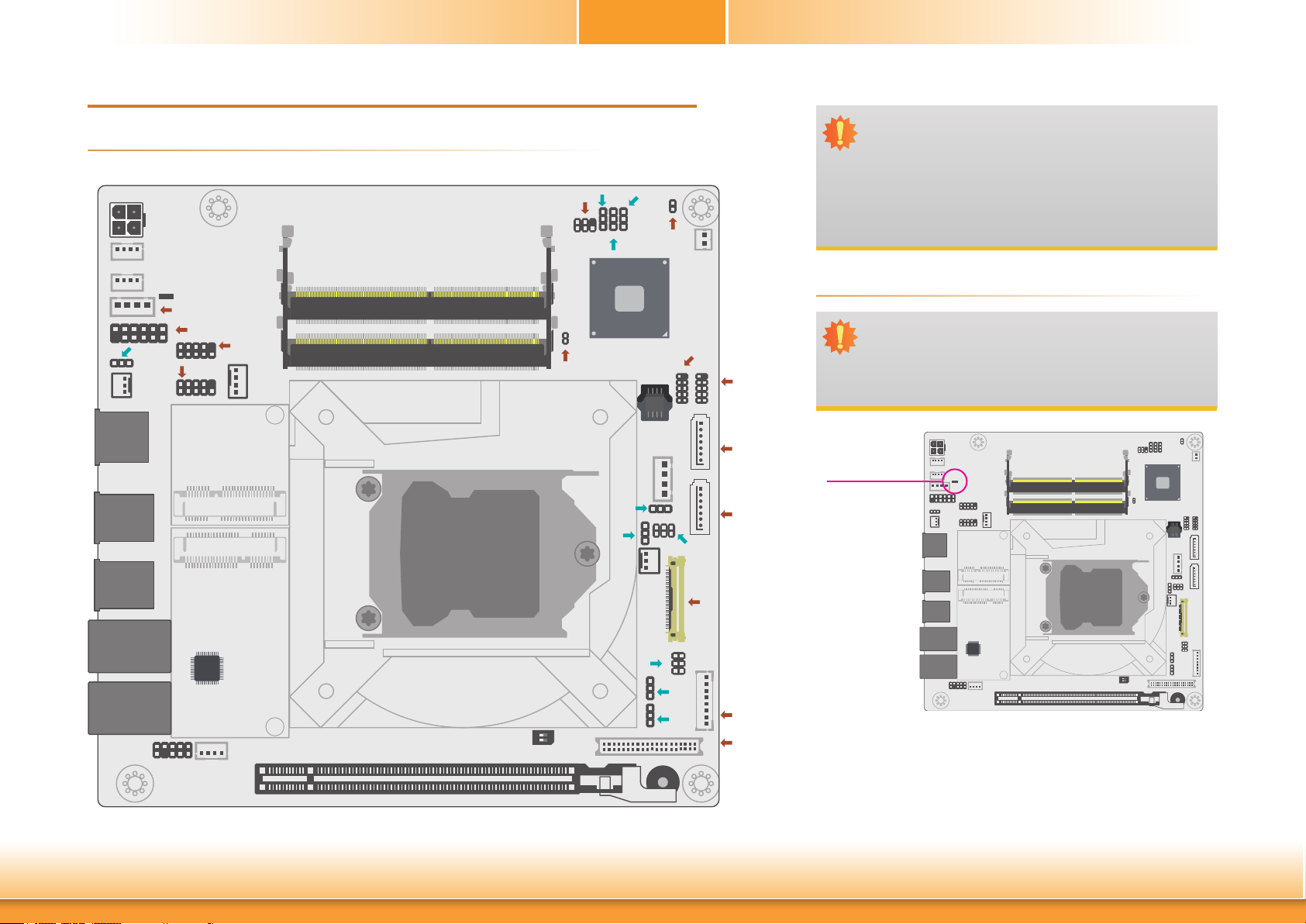
► Board Layout
DC In
3
1
4
2
Digital I/O Power
1
Digital I/O
1
1 4
11
JP1
1
System
Fan 1
DP++
USB 3.0
(USB 3/4)
USB 3.0
(USB 1/2)
Standby Power LED
ATX Power
1
Front Panel
2
2
1
2
1
COM 4
9
9
COM 3
1
Mini PCIe 2
Mini PCIe 1
CPU
Fan
DDR4_2 SODIMM
DDR4_1 SODIMM
Chapter 2
2
1
5
JP4
1
Chassis
Intrusion
1 1 1
Intel
Q170
JP9
JP2
1
ME Disable
SPI
Flash
BIOS
SATA
Power
1
4
1
2 6
1
1
System
Fan 2
Battery
10
2
1
5
1
2
10
9
1
2
JP10
eDP
9
1
1
1
Important:
Electrostatic discharge (ESD) can damage your board, processor, disk drives, add-in boards, and other components.
Perform installation procedures at an ESD workstation only.
If such a station is not available, you can provide some ESD
protection by wearing an antistatic wrist strap and attaching
it to a metal part of the system chassis. If a wrist strap is
unavailable, establish and maintain contact with the system
chassis throughout any procedures requiring ESD protection.
► Standby Power LED
Important:
When the Standby Power LED lit red, it indicates that there
is power on the system board. Power-off the PC then unplug
the power cord prior to installing any devices. Failure to do
so will cause severe damage to the motherboard and components.
SATA 0
Standby Power LED
SATA 3
LAN 1
Intel
I211AT
LAN 2
9 1
Front
Audio
10 2
1
Speaker
PCIe x16 (PCIE1)
Chapter 2 Hardware Installation
Socket LGA1151
SW1
JP8
21
65
JP6
JP7
1
40
LCD/Inverter
Power
LVDS LCD
Panel
This LED lights red when the system is in the standby mode. It indicates that is supplied to the system board. Power-off the PC and then
unplug the power cord prior to installing any devices. Failure to do so
will cause severe damage to the motherboard and components.
1
1
2
ON
1
1 39
2
Buzzer
8
www.d.com
Page 9
Chapter 2
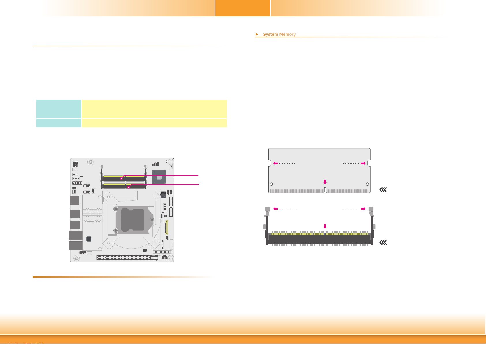
► System Memory
► System Memory
The system board supports the following memory interface.
Single Channel (SC)
Data will be accessed in chunks of 64 bits from the memory channels.
Dual Channel (DC)
Data will be accessed in chunks of 128 bits from the memory channels. Dual channel provides
better system performance because it doubles the data transfer rate.
Single Channel
Dual Channel DIMMs of the same memory configuration are on different channels.
BIOS Setting
Enable or disable ECC in the “Advanced” menu of the BIOS. Refer to Chapter 3 for more information.
DIMMs are on the same channel. DIMMs in a channel can be identical or completely different. However, we highly recommend using
identical DIMMs. Not all slots need to be populated.
DDR4_2
DDR4_1
Installing the SO-DIMM Module
Before installing the memory module, please make sure that the following safety cautions are
well-attended.
1. Make sure the PC and all other peripheral devices connected to it has been powered
down.
2. Disconnect all power cords and cables.
3. Locate the SO-DIMM socket on the system board
4. Make sure the notch on memory card is aligned to the key on the socket.
Retention Notch
Notch
DDR4 SO-DIMM
Retention Clip
Features
Chapter 2 Hardware Installation
Key
Socket Top View
• Two 260-pin SODIMM up to 32GB
• Dual Channel DDR4 1866/2133MHz
9
www.d.com
Page 10
Notch
Retention Notch
Key
Socket Top View
DDR4 SO-DIMM
Retention Clip
► System Memory
► Installing the SO-DIMM Module
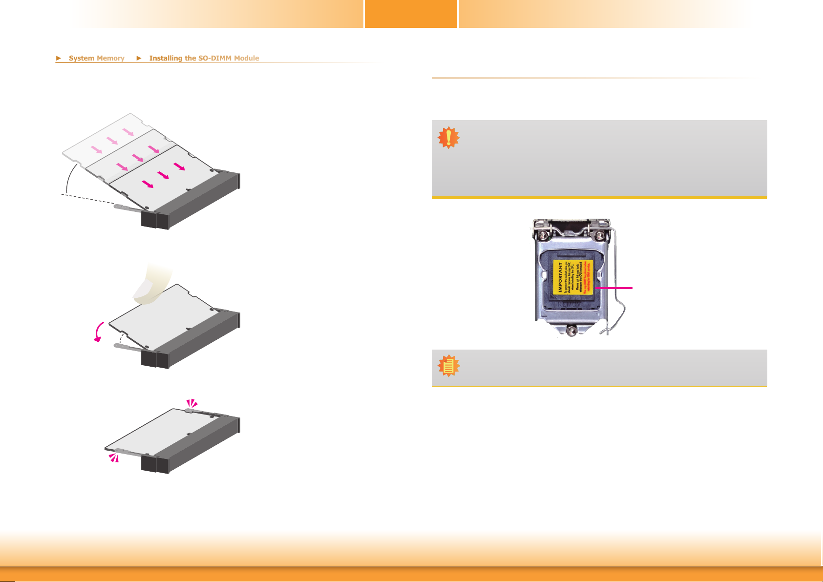
Please follow the steps below to install the memory card into the socket.
Chapter 2
► CPU
The system board is equipped with a surface mount LGA 1151 socket. This socket is exclusively designed for installing a LGA 1151 packaged Intel CPU.
45°
Step 1
Step 2
Step 3
Step 1:
Insert the memory card into the
slot while making sure 1) the
notch and the key are aligned,
and 2) the non-connector end
rises approximately 45 degrees
horizontally. Press the card firmly
into the socket while applying and
maintaining even pressure on both
ends.
Step 2:
Press the end of the card far from
the socket down while making
sure the retention notch and the
clip align as indicated by the dotted line in the illustration. If the
retention notch and the clip do not
align, please remove the card and
re-insert it. Press the card all the
way down.
Step 3:
The clips snap automatically and
abruptly to the retention notches
of the card sounding a distinctive
click, and lock the card in place.
Inspect that the clip sits in the
notch. If not, please pull the clips
outward, release and remove the
card, and mount it again.
Important:
1. Before you proceed, make sure (1) the LGA 1151 socket comes with a protective cap, (2) the cap is not damaged and (3) the socket’s contact pins are not
bent. If the cap is missing or the cap and/or contact pins are damaged, contact
your dealer immediately.
2. Make sure to keep the protective cap. RMA requests will be accepted and processed only if the LGA 1151 socket comes with the protective cap.
Protective
cap
Note:
The system board used in the following illustrations may not resemble the actual
board. These illustrations are for reference only.
Chapter 2 Hardware Installation
10
www.d.com
Page 11
Chapter 2
► CPU
► CPU
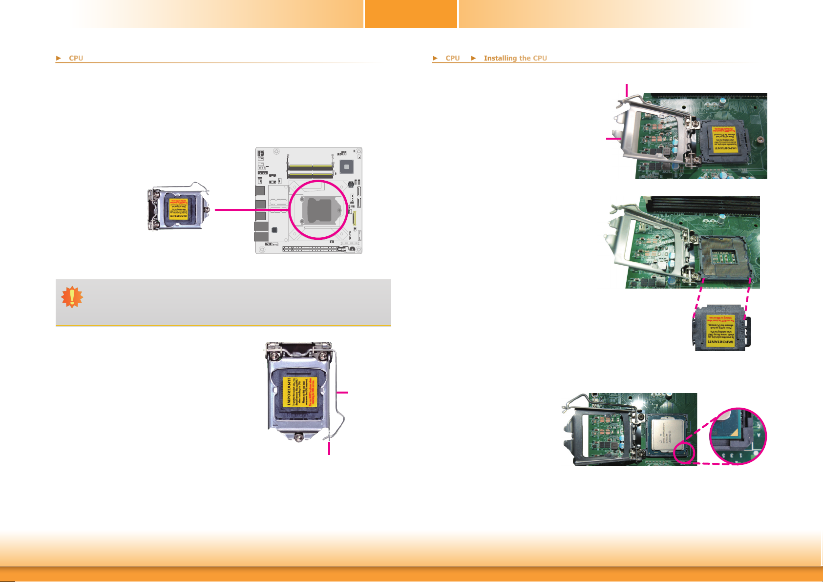
► Installing the CPU
Installing the CPU
1. Make sure the PC and all other peripheral devices connected to it have been powered
down.
2. Disconnect all power cords and cables.
3. Locate the LGA 1151 CPU
socket on the system board.
Important:
The CPU socket must not come in contact with anything other than the CPU. Avoid
unnecessary exposure. Remove the protective cap only when you are about to install the CPU.
4. Unlock the socket by pressing
the load lever down, moving
it sideways until to escape the
retention tab. Lift the load lever
up when it’s released.
Load lever
Retention tab
5. Lift the load lever and the load
plate all the way up as shown in
the photo.
6. Remove the protective cap from
the CPU socket. The cap is used
to protect the CPU socket against
dust and harmful particles. Remove the protective cap only
when you are about to install the
CPU.
7.1.Insert the CPU into
the socket. The gold
triangular mark on the
CPU must align with
the chamfer corner of
the CPU socket shown
in the photo.
Load lever
Load
plate
Protective cap
Golden triangular
mark
Chapter 2 Hardware Installation
11
www.d.com
Page 12
Chapter 2
► CPU
► Installing the CPU
► CPU
► Installing the CPU
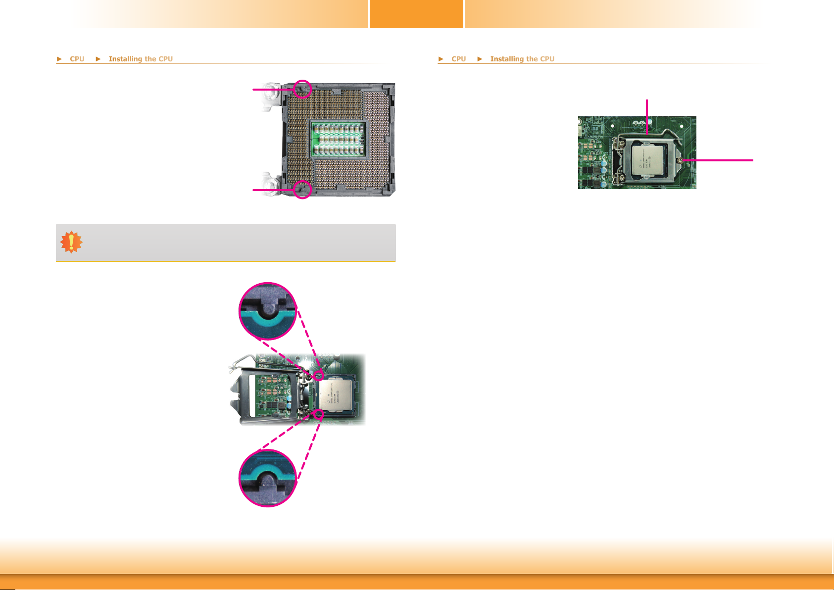
7.2. Two keys on the socket and notches on
the CPU also facilitate
alignment.
Important:
The CPU will fit in only one orientation and can easily be seated without exerting
any force.
7.3.The CPU’s notch will
fit into the socket’s
alignment key when
it’s seated in the correct orientation.
Alignment key
Alignment key
8. Close the load plate
then push the load lever down.
While closing the load
plate, make sure the
front edge of the load
plate slides under the
retention knob.
9. Press down the load
lever and hook it under the retention tab.
Load lever
Retention knob
Chapter 2 Hardware Installation
12
www.d.com
Page 13
Installing the Fan and Heat Sink
► CPU
► CPU
► Installing the Fan and Heat Sink
Chapter 2
The CPU must be kept cool by using a CPU fan with heat sink. Without sufficient air circulation across the CPU and heat sink, the CPU will overheat damaging both the CPU and system
board.
Note:
A boxed Intel® processor already includes the CPU fan and heat sink assembly. If
your CPU was purchased separately, make sure to only use Intel®-certified fan and
heat sink.
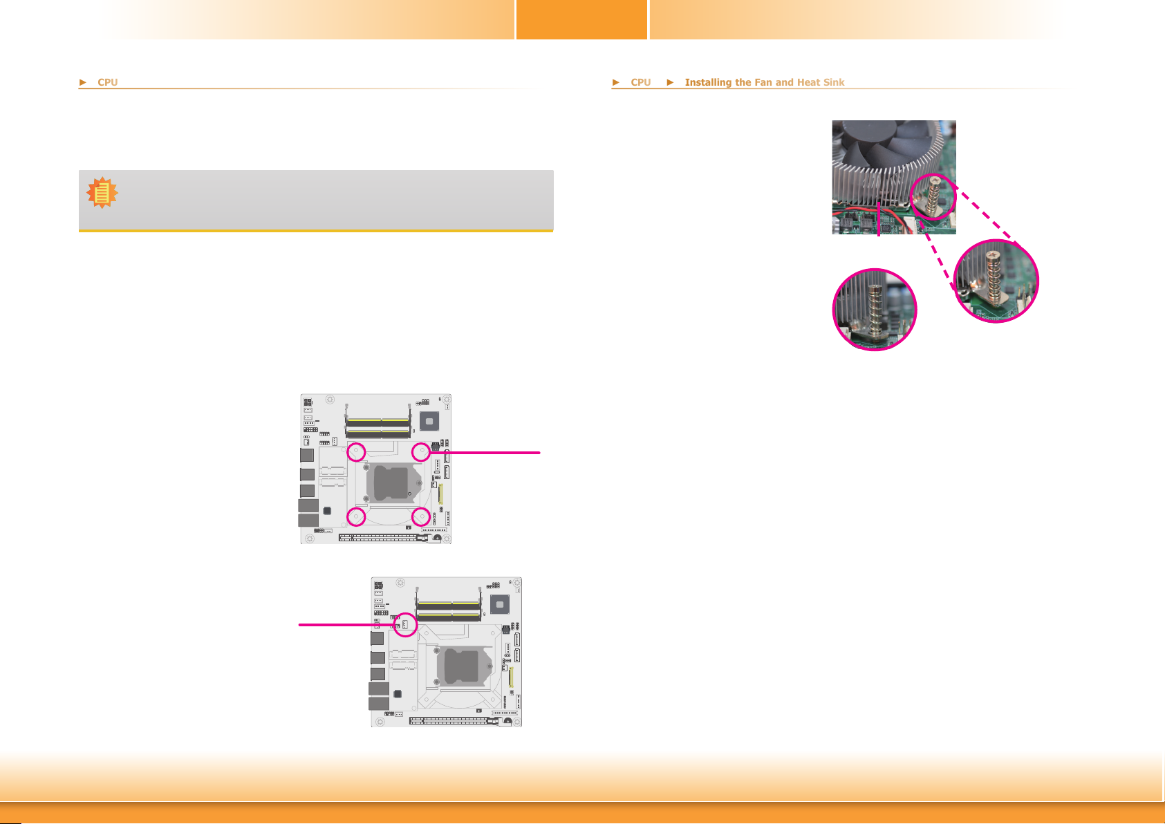
1. Before you install the fan / heat sink, you must apply a thermal paste onto the top of
the CPU. The thermal paste is usually supplied when you purchase the fan / heat sink
assembly. Do not spread the paste all over the surface. When you later place the heat
sink on top of the CPU, the compound will disperse evenly.
Some heat sinks come with a patch of pre-applied thermal paste. Do not apply thermal
paste if the fan / heat sink already has a patch of thermal paste on its underside. Peel
the strip that covers the paste before you place the fan / heat sink on top of the CPU.
2. Place the heat sink on
top of the CPU. The 4
spring screws around
the heat sink, which
are used to secure
the heat sink onto the
system board, must
match the 4 mounting holes around the
socket.
Mounting holes
4. Screw tight two of
the spring screws at
opposite corners into
the mounting holes.
And then proceed with
the other two spring
screws.
Heat sink
“Unlocked” position
of push-pin
“Locked” position of
push-pin
5. Connect the CPU fan’s
cable to the CPU fan
connector on the system board.
3. Orient the heat sink
so that the CPU fan’s
cable is nearest the
CPU fan connector.
Chapter 2 Hardware Installation
CPU fan
connector
13
www.d.com
Page 14
Chapter 2
► Jumper Settings
► Jumper Settings
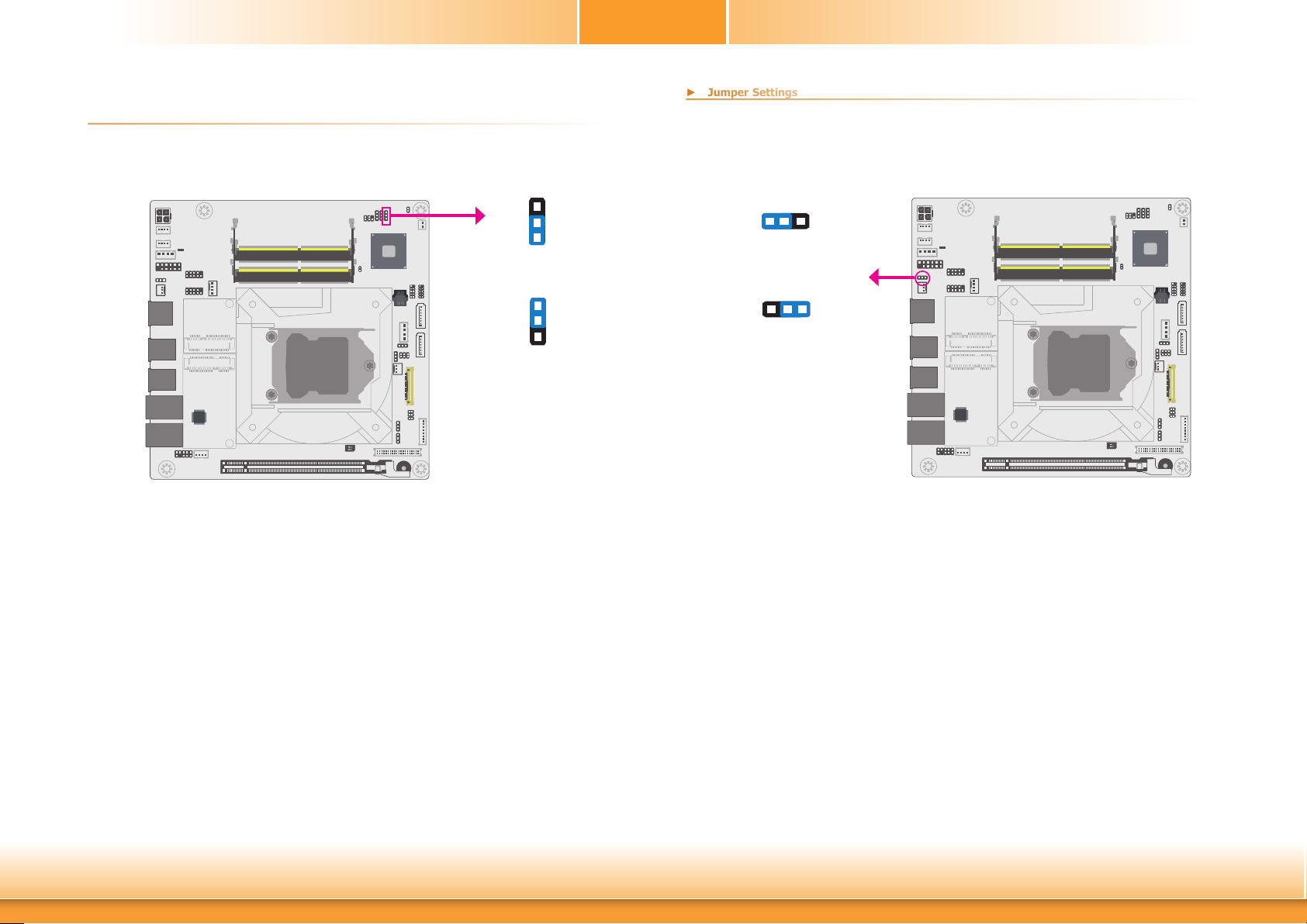
Clear CMOS Data
If any anomaly of the followings is encountered —
a) CMOS data is corrupted;
b) you forgot the supervisor or user password;
c) failure to start the system due to BIOS mis-configuration
JP5
3
2
1
1-2 On:
Normal (default)
3
2
1
2-3 On:
Clear CMOS Data
Auto Power-on Select
1 32
Power-on via Power Button
JP1 is used to select the method of powering on the system. If you want the system to power-on whenever AC power comes in, set JP1 pins 2 and 3 to On. If you want to use the power
button, set pins 1 and 2 to On.
When using the JP1 “Power On” feature to power the system back on after a power failure
occurs, the system may not power on if the power lost is resumed within 5 seconds (power
flicker).
1-2 On:
(default)
1 32
2-3 On:
Power-on via AC power
JP1
— it is suggested that the system be reconfigured with default values stored in the ROM BIOS.
To load the default values stored in the ROM BIOS, please follow the steps below.
1. Power-off the system and unplug the power cord.
2. Put a jumper cap on JP5’s pin 2 and pin 3. Wait for a few seconds and set JP5 back to
3. Plug the power cord and power-on the system.
Chapter 2 Hardware Installation
its default setting, i.e. jumper cap on pin 1 and pin 2.
14
www.d.com
Page 15

2
► Jumper Settings
► Jumper Settings
1
4
3
6
5
1-2 On: +12V
2
1
4
3
5
6
3-4 On: +5V
2
JP8
1
4
3
6
5
5-6 On: +3.3V (default)
Chapter 2
PCIE1 Signal SelectLVDS Panel Power Select
JP8 is used to select the power supplied with the LCD panel.
Chapter 2 Hardware Installation
Important:
Before powering-on the system, make sure that the power settings of JP8 match the
LCD panel’s specification. Selecting the incorrect voltage will seriously damage the
LCD panel.
PCIE1
SW1 is used to select the signal of the PCIE1 slot, a PCIe x16 socket that can be configured to
multiple signal lane settings as listed below.
PCIE1 Signal Select SW1
PCIe x16 (default) 1 On, 2 On
Two PCIe x8 1 Off, 2 On
One PCIe x8 + Two PCIe x4 1 Off, 2 Off
15
www.d.com
Page 16
Chapter 2
► Jumper Settings
► Jumper Settings
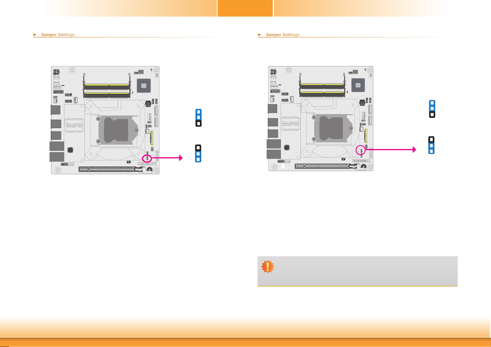
LCD/Inverter Power Select
JP7
JP7 is used to select the power level of the LCD inverter power connector.
1
2
3
1-2 On: +12V
(default)
1
2
3
2-3 On: +5V
LVDS Backlight Power Select
1
2
3
1-2 On: +3.3V
(default)
1
JP6
JP6 is used to select the power level of backlight brightness control of the LVDS port: +3.3V
or +5V.
2
3
2-3 On: +5V
Chapter 2 Hardware Installation
Important:
Before powering-on the system, make sure that the power settings of JP6 match
the power specification of backlight control. Selecting the incorrect voltage will seriously damage the backlight.
16
www.d.com
Page 17
Chapter 2
► Jumper Settings
► Jumper Settings
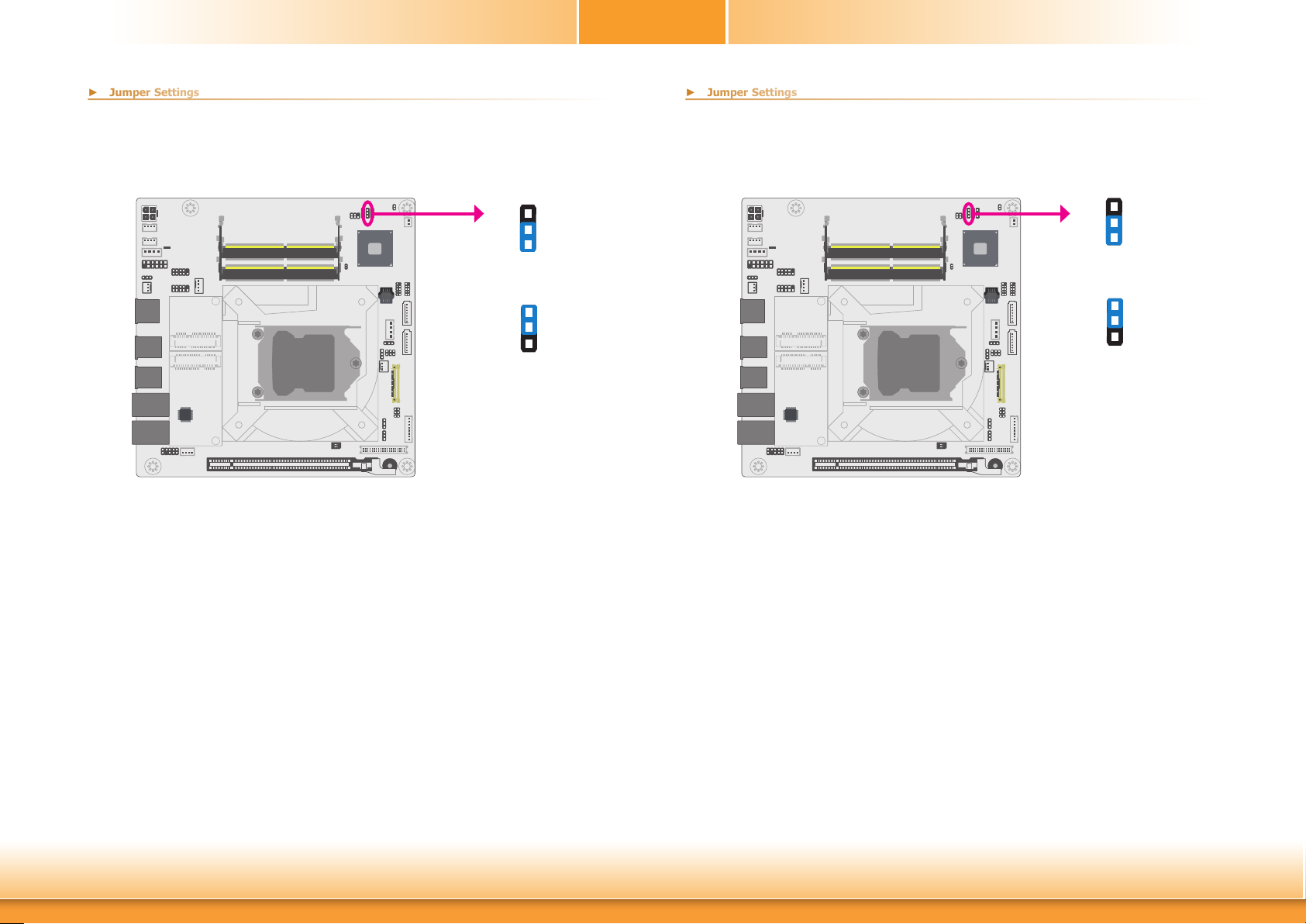
Mini PCIe 1 Signal Select
JP4
mSATA (default)
JP4 is used to select the Mini PCIe 1 (full-size) signal: mini PCIe or mSATA (default).
3
2
1
1-2 On:
mini PCIe
3
2
1
2-3 On:
Mini PCIe 2 Signal Select
JP3
mini PCIe (default)
JP3 is used to select the Mini PCIe 2 (half-size) signal: mini PCIe (default) or mSATA.
3
2
1
1-2 On:
3
2
1
2-3 On:
mSATA
Chapter 2 Hardware Installation
17
www.d.com
Page 18
Chapter 2
► Jumper Settings
► Jumper Settings
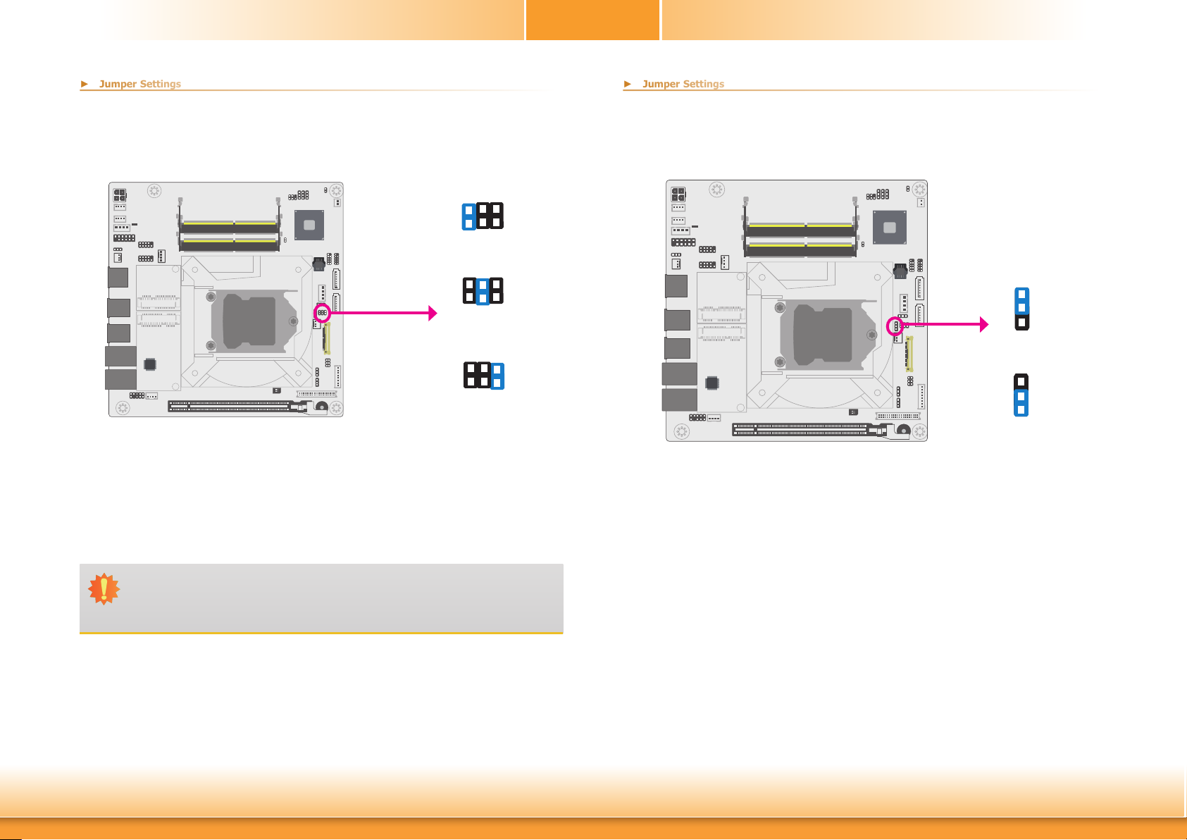
eDP Panel Power Select
JP10
6
42
153
1-2 On: +12V
6
2
4
1 5
3
3-4 On: +5V
4
6
2
1 5
3
5-6 On: +3.3V (default)
eDP Inverter Power Select
JP2
1
2
3
1-2 On: +12V
(default)
1
2
3
2-3 On: +5V
JP10 is used to select the power supplied with the panel connected via the eDP port.
Chapter 2 Hardware Installation
JP2 is used to select the power level of the eDP inverter power connector.
Important:
Before powering-on the system, make sure that the power settings of JP10 match
the panel’s specification. Selecting the incorrect voltage will seriously damage the
LCD panel.
18
www.d.com
Page 19
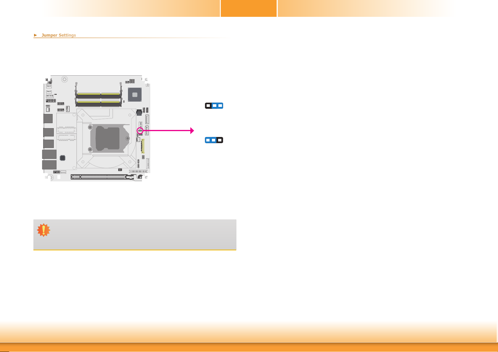
eDP Backlight Power Select
► Jumper Settings
JP9
1
3 2
1-2 On: +3.3V
(default)
13
2
2-3 On: +5V
Chapter 2
JP9 is used to select the power level of backlight brightness control of the eDP port: +3.3V or
+5V.
Chapter 2 Hardware Installation
Important:
Before powering-on the system, make sure that the power settings of JP9 match
the power specification of backlight control. Selecting the incorrect voltage will seriously damage the backlight.
19
www.d.com
Page 20
Chapter 2
► Rear Panel I/O Ports
► Rear Panel I/O Ports
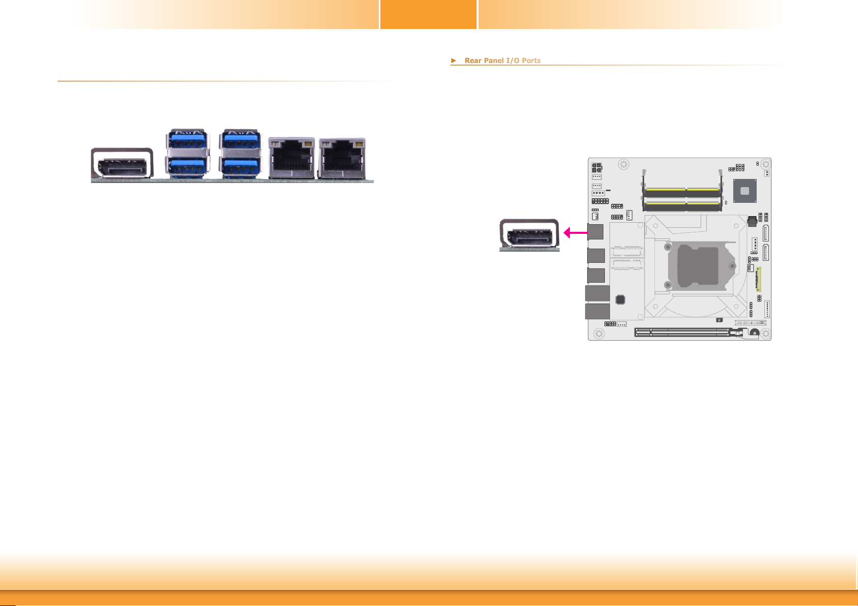
▲ USB 3.0 ▲ DP++ ▲ LAN 1 ▲ LAN 2
The rear panel I/O ports consist of the following:
• 1 DP++
• 4 USB 3.0 ports
• 2 RJ45 LAN ports
Graphics Interface
The display ports consist of the following:
• 1 DP++ port
DP++
Chapter 2 Hardware Installation
DP++ Port
The DP port is a digital display interface used to connect a display device such as a computer
monitor. It is used to transmit audio and video simultaneously. The interface, which is developed by VESA, delivers higher performance features than any other digital interface.
20
www.d.com
Page 21
Chapter 2
► Rear Panel I/O Ports
► Rear Panel I/O Ports
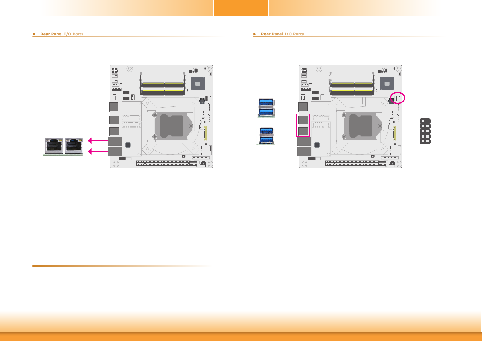
RJ45 LAN Ports
LAN 1
The two LAN ports allow the system board to connect to a local area network by means of a
network hub.
BIOS Setting
Configure the onboard LAN ports in the Advanced menu (“ACPI Configuration” submenu) of
the BIOS. Refer to the chapter 3 for more information.
LAN 2
LAN 1
LAN 2
USB Ports
USB 7-8 (left)
USB 4
USB 3
USB 3.0
USB 2
USB 1
USB 3.0
The USB device allows data exchange between your computer and a wide range of simultaneously accessible external Plug and Play peripherals. The system board is equipped with four
onboard USB 3.0 ports (USB3_1-2/USB3_3-4). The 10-pin connectors allow you to connect 4
additional USB 2.0 ports (USB2_5-6/USB2_7-8). The additional USB ports may be mounted on
a card-edge bracket. Install the card-edge bracket to an available slot at the rear of the system chassis and then insert the USB port cables to a connector.
USB 5-6 (right)
USB 2.0
10
N. C.
GND
+Data1
-Data1
VCC
9
GND
+Data0
-Data0
VCC
12
Driver Installation
Install the LAN drivers. Refer to the chapter 4 for more information.
Features
• Intel® I211AT PCI Express Gigabit Ethernet controller
• Intel® I219LM PCIe with iAMT11.0 Gigabit Ethernet Phy
Chapter 2 Hardware Installation
Wake-On-USB Keyboard/Mouse
The Wake-On-USB Keyboard/Mouse function allows you to use a USB keyboard or USB mouse
to wake up a system from the S3 (STR - Suspend To RAM) state.
BIOS Setting
Configure these onboard USB devices in the Advanced menu (“USB Configuration” submenu)
of the BIOS. Refer to the chapter 3 for more information.
Driver Installation
You may need to install the proper drivers in your system operation to use the USB device.
Refer to your operating system’s manual or documentation for more information.
21
www.d.com
Page 22
Chapter 2
► Internal I/O Connectors
► Internal I/O Connectors
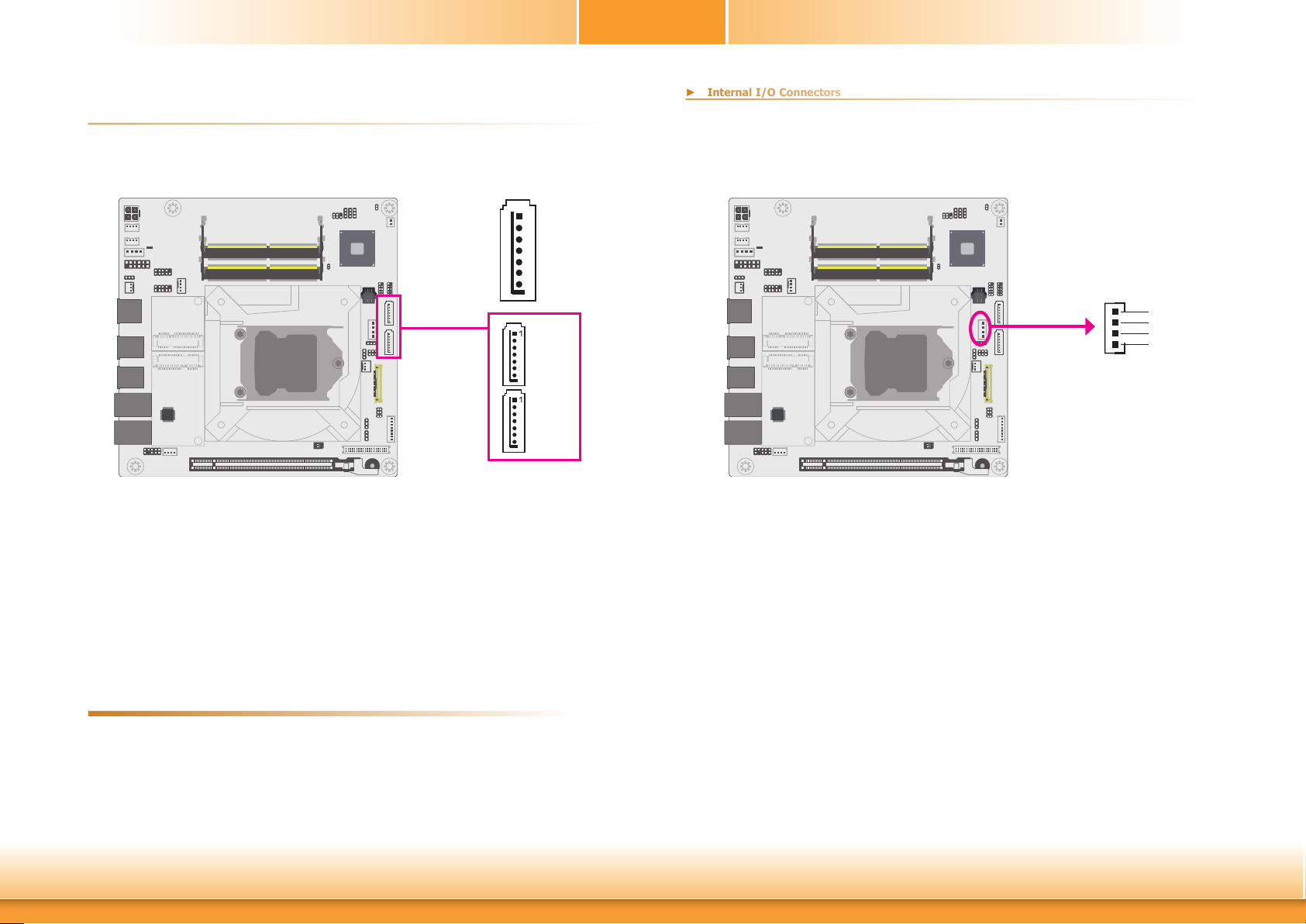
SATA (Serial ATA) Connectors
GND
1
TXP
TXN
GND
RXN
RXP
7
GND
SATA 0
SATA 3
SATA 3.0 6Gb/s
The Serial ATA connectors are used to connect Serial ATA devices. Connect one end of the Serial ATA data cable to a SATA connector and the other end to your Serial ATA device.
SATA (Serial ATA) Power Connector
SATA
Power
The SATA power connector supplies power to the SATA drive. Connect one end of the provided
power cable to the SATA power connector and the other end to your storage device.
1
4
+12V
Ground
Ground
+5V
BIOS Setting
Configure the Serial ATA drives in the Advanced menu (“SATA Configuration” submenu) of the
BIOS. Refer to the chapter 3 for more information.
Features
2 x Serial ATA 3.0 ports with data transfer rate up to 6Gb/s (SATA 0 and SATA 3)
Chapter 2 Hardware Installation
22
www.d.com
Page 23
Chapter 2
► Internal I/O Connectors
► Internal I/O Connectors
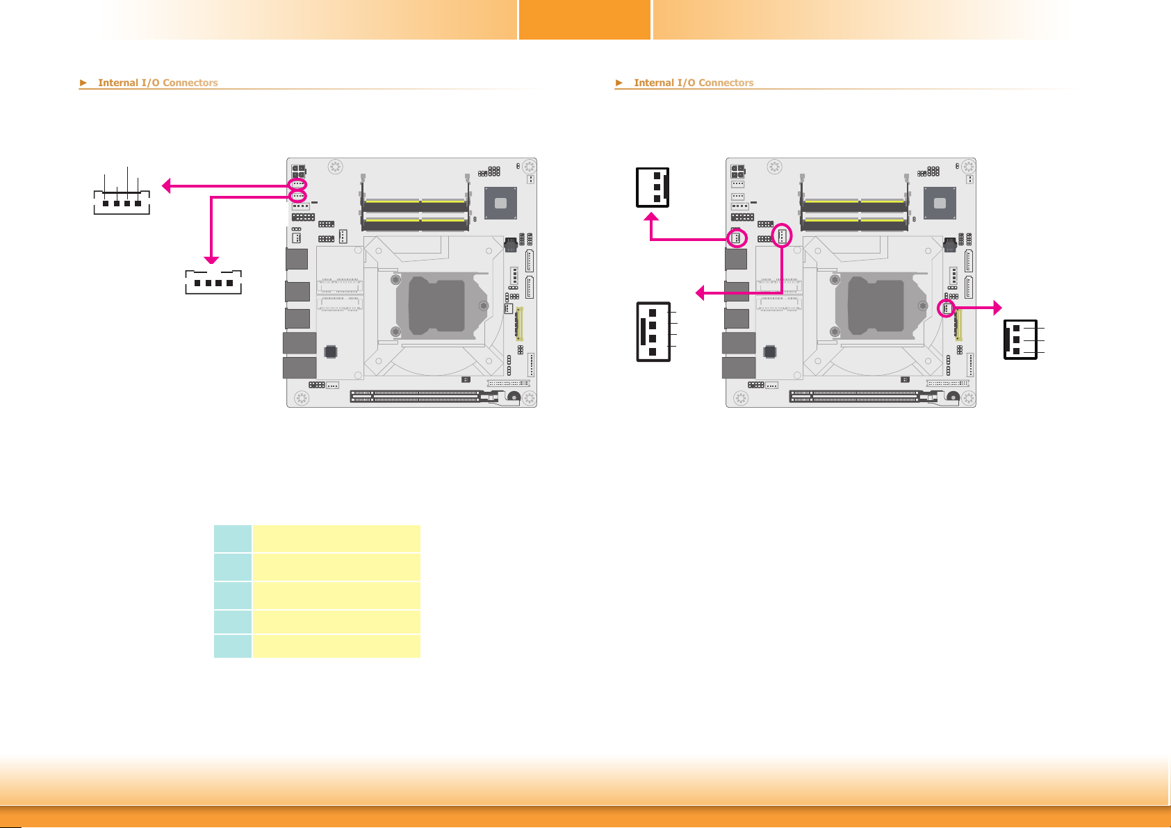
Digital I/O
Ground
+5V
The 4-bit Digital I/O connector provides powering-on function to external devices that are connected to these connectors.
5VDU
Digital I/O
+12V
1
Digital I/O Power
Digital I/O
1
▼ Digital I/O Connector Pin assignment
Pin Function
Cooling Fan Connectors
3
Sense
Power
1
Ground
System Fan 1
CPU Fan
1
Ground
Power
Sense
Speed
4
Control
The fan connectors are used to connect cooling fans. The cooling fans will provide adequate
airflow throughout the chassis to prevent overheating the CPU and system board components.
BIOS Setting
The Advanced menu (“SIO NUVOTON6106D” submenu) of the BIOS will display the current
speed of the cooling fans. Refer to the chapter 3 for more information.
System Fan 2
1
3
Ground
Power
Sense
Chapter 2 Hardware Installation
1
2
3
4
DIO0
DIO1
DIO2
DIO3
23
www.d.com
Page 24
Chapter 2
► Internal I/O Connectors
► Internal I/O Connectors
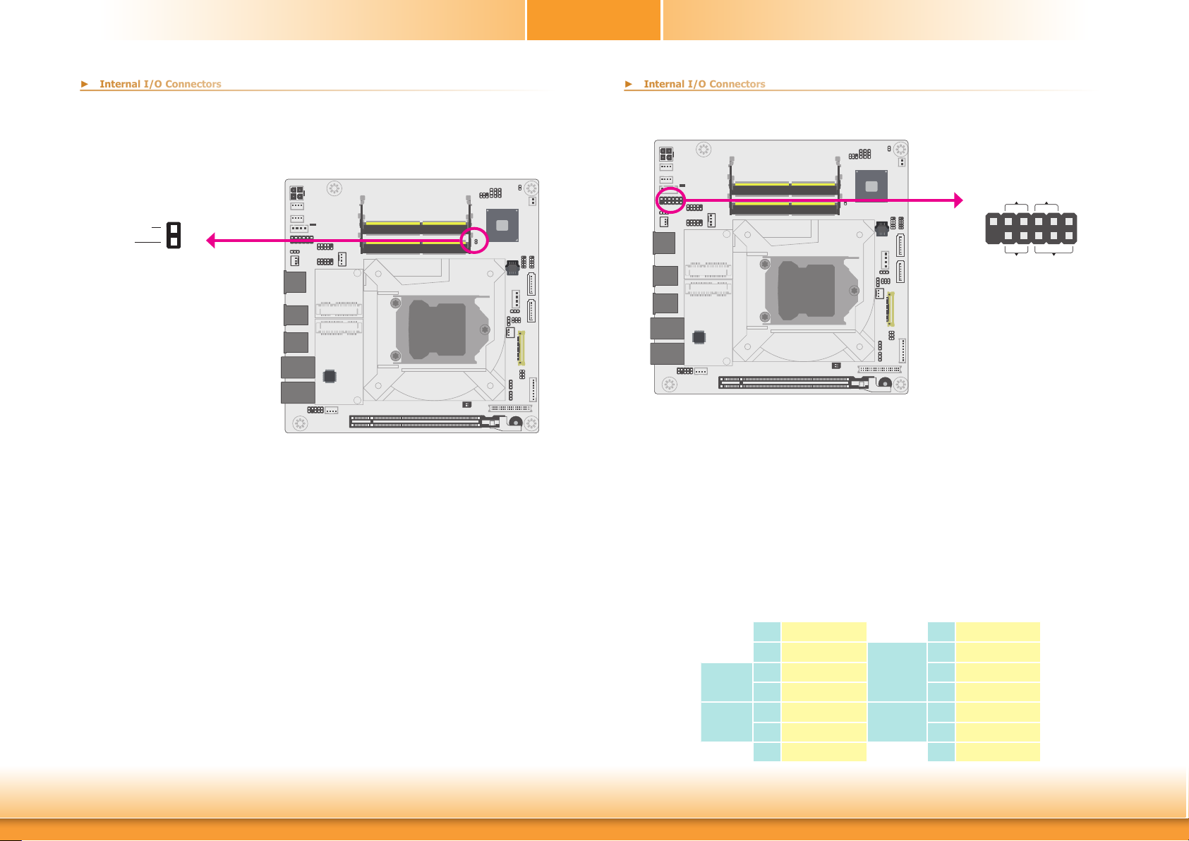
Chassis Intrusion Connector
Ground
Signal
The board supports the chassis intrusion detection function. Connect the chassis intrusion
sensor cable from the chassis to this connector. When the system’s power is on and a chassis
intrusion occurred, an alarm will sound. When the system’s power is off and a chassis intrusion
occurred, the alarm will sound only when the system restarts.
Chassis
2
Intrusion
1
Front Panel Connector
HD-LEDRESET
11
12
PWR-LEDATX-SW
▲ Front Panel Connector
HDD-LED - Hard Disk Drive LED
Lighting of the LED indicates that the hard drive is being accessed.
RESET - Reset Switch
This switch allows you to reboot without having to power off the system.
PWR-LED - Power/Standby LED
When the system’s power is on, this LED will light up. When the system is in the S1 (POS
- Power On Suspend) state, it will blink at 1-second intervals. When the system is in the S3
(STR - Suspend To RAM) state, it will blink at 4-second intervals.
1
2
Chapter 2 Hardware Installation
ATX-SW - ATX Power Switch
This switch is used to power on or off the system.
Pin Assignment Pin Assignment
1 N.C.
HD-LED
RESET
24
3 HDD Power 4 LED Power
5 Signal 6 Signal
7 Ground
9 Signal 10 Signal
11 N.C. 12 ---
▼ Front Panel Pin Assignment
PWR-LED
ATX-SW
2 LED Power
8 Ground
www.d.com
Page 25
Chapter 2
► Internal I/O Connectors
► Internal I/O Connectors
► Expansion Slots
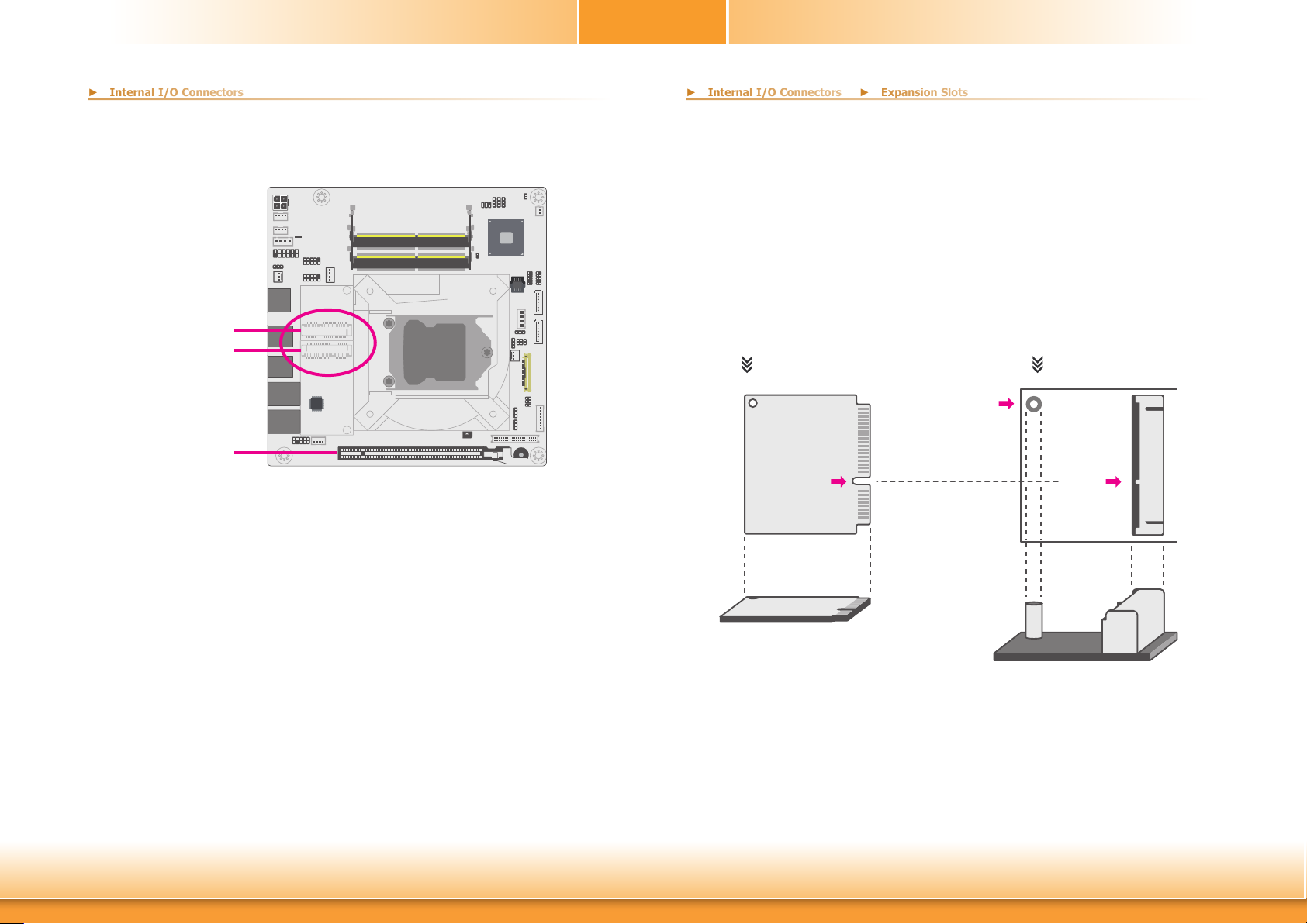
Expansion Slots
Half-size Mini PCIe
Full-size Mini PCIe
PCI Express x16
(PCIE1)
PCI Express x16 Slot
Install a PCI Express x16 graphics card that complies to the PCI Express specifications into the
PCI Express x16 slot. To install a graphics card into the x16 slot, align the graphics card to the
socket and perpendicularly to the board, be cautious in aligning the locations of notch and key,
and then press the card down firmly until it is completely seated. The retaining clip of the slot
will close up automatically to hold the graphics card in place.
Installing the Mini PCIe card
Before installing the Mini PCIe module into the Mini PCIe socket, please make sure that the
following safety cautions are well-attended.
1. Make sure the PC and all other peripheral devices connected to it has been powered
down.
2. Disconnect all power cords and cables.
3. Locate the Mini PCIe socket on the system board
4. Make sure the notch on card is aligned to the key on the socket.
mSATA Half Size Mini PCIe Socket
Stand-off
Notch
Key
Mini PCIe Socket
The Mini PCIe socket is used to install a 52-pin Mini PCIe card. Mini PCIe card is a small form
factor PCIe card with the same signal protocol, electrical definitions, and configuration definitions as the conventional PCIe. The board is layed out for one half-size and one full-size Mini
PCIe slots with pre-installed standoffs.
Jumper Settings
The PCIe x16 slot can be switched between riser card and x16 signal, and the two Mini PCIe
slots can be switched between PCIe signal and m-SATA signal. The settings are configured via
jumpers as previously instructed in Chapter 2.
Chapter 2 Hardware Installation
25
www.d.com
Page 26
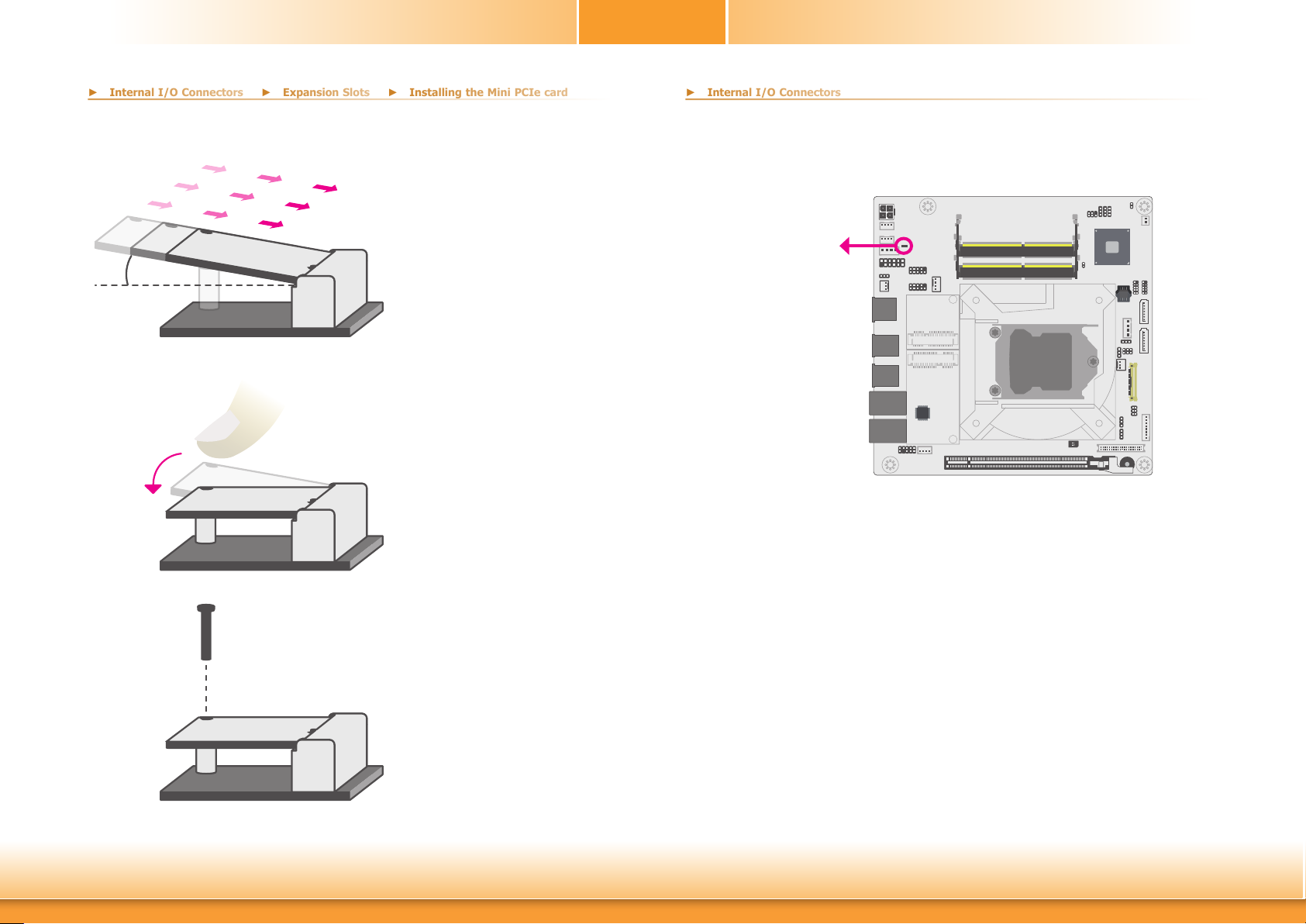
Please follow the steps below to install the card into the socket.
► Internal I/O Connectors
► Expansion Slots
► Installing the Mini PCIe card
► Internal I/O Connectors
Chapter 2
Standby Power LED
Step 1:
Insert the card into the socket at an
angle while making sure the notch
and key are perfectly aligned.
Step 2:
Press the end of the card far from
the socket down until against the
stand-off.
Step 3:
Screw tight the card onto the standoff with a screw driver and a standoff screw until the gap between the
card and the stand-off closes up.
The card should be lying parallel to
the board when it’s correctly mount-
ed.
Standby Power LED
This LED will light red when the system is in the standby mode. It indicates that there is power on the system board. Power-off the PC and then unplug the power cord prior to installing
any devices. Failure to do so will cause severe damage to the motherboard and components.
Chapter 2 Hardware Installation
26
www.d.com
Page 27
Chapter 2
► Internal I/O Connectors
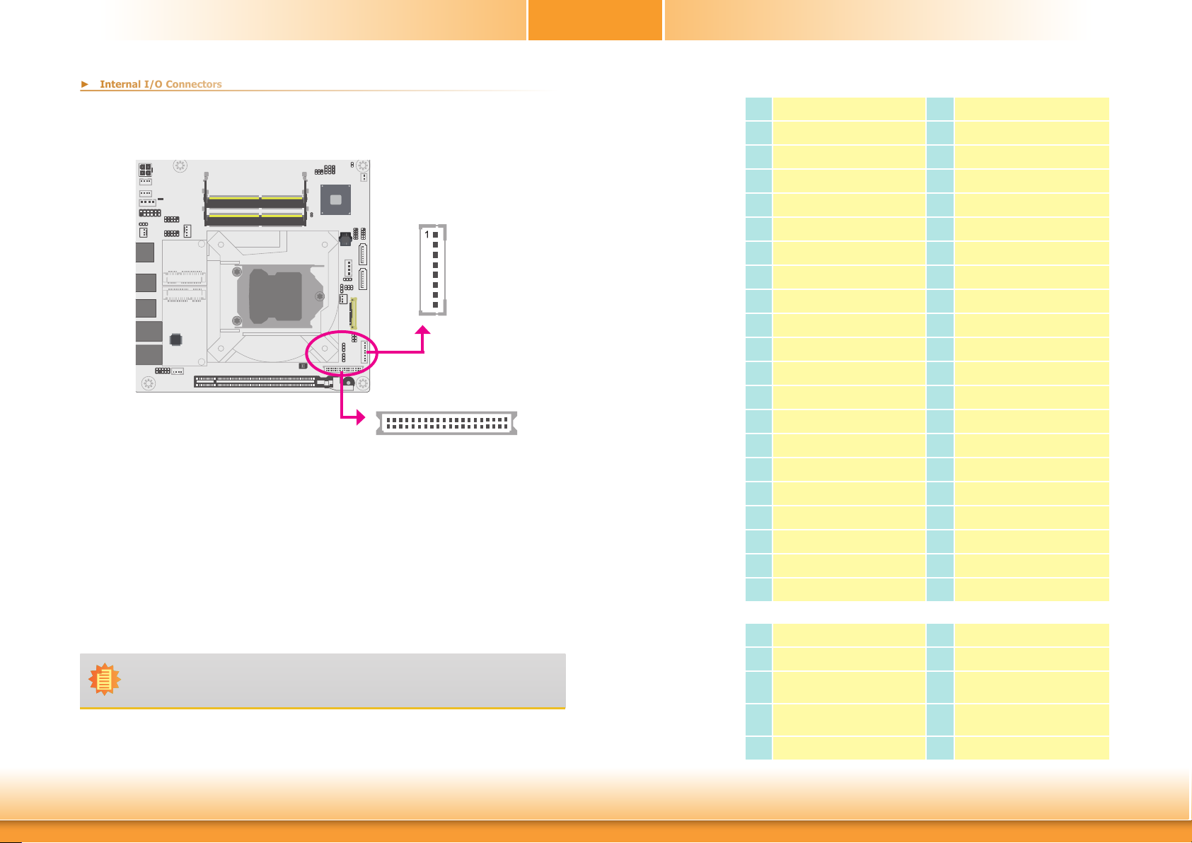
LVDS Panel
LCD/Inverter
Power
1
2
LVDS LCD
Panel
The system board allows you to connect a LCD Display Panel by means of the LVDS LCD panel
connector and the LCD/Inverter power connector. These connectors transmit video signals and
power from the system board to the LCD Display Panel.
Refer to the right side for the pin functions of these connectors.
BIOS Setting
Configure the LCD panel in the Advanced Features submenu of the BIOS. Refer to the chapter
3 for more information.
39
40
LVDS LCD Panel
Pin Assignment
Pin Function Pin
GND
1
LVDS_Out3+ (Odd_3+)
3
LVDS_Out3- (Odd_3-)
5
GND
7
LVDS_Out2+ (Odd_2+)
9
LVDS_Out2- (Odd_2-)
11
GND
13
LVDS_Out1+ (Odd_1+)
15
LVDS_Out1- (Odd_1-)
17
GND
19
LVDS_Out0+ (Odd_0+)
21
LVDS_Out0- (Odd_0-)
23
GND
25
LVDS_CLK1+ (Odd_CLK+)
27
LVDS_CLK1- (Odd_CLK-)
29
GND
31
LVDS_DDC_CLK
33
LVDS_DDC_DATA
35
Panel Power
37
Panel Power
39
2
4
6
8
10
12
14
16
18
20
22
24
26
28
30
32
34
36
38
40
Function
GND
LVDS_Out7+ (Even_3+)
LVDS_Out7- (Even_3-)
GND
LVDS_Out6+ (Even_2+)
LVDS_Out6- (Even_2-)
GND
LVDS_Out5+ (Even_1+)
LVDS_Out5- (Even_1-)
GND
LVDS_Out4+(Even_0+)
LVDS_Out4- (Even_0-)
GND
LVDS_CLK2+ (Even_CLK+)
LVDS_CLK2- (Even_CLK-)
GND
NC
+3.3V
Panel Power
Panel Power
Note:
DFI board's LVDS connector: Hirose DF13-40DP-1.25V(91)/40P/1.25mm; cable side
connector: Hirose DF13-40DS-1.25C.
Chapter 2 Hardware Installation
LCD/Inverter Power
Pin Assignment
27
Pin Function Pin
GND
1
GND
2
Panel Inverter Brightness
3
Voltage Control
Panel Power
4
5
6
7
8
Function
+3.3V
Panel Backlight On/O
Control
12V (default)/5V
12V (default)/5V
www.d.com
Page 28
Chapter 2
► Internal I/O Connectors
► Internal I/O Connectors
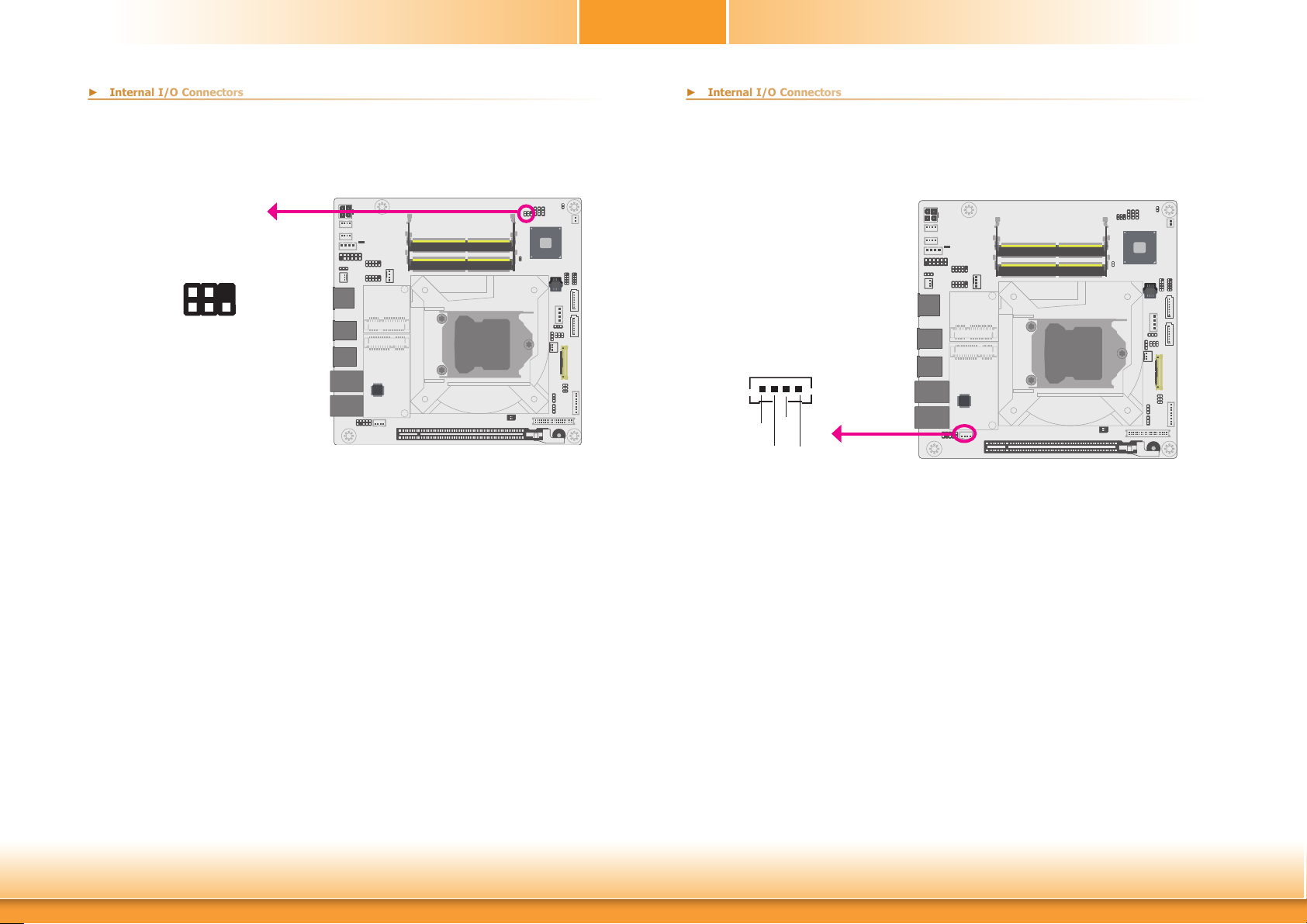
SMBus Connector
SMBus
GND
SMBUS_Data
3V3SB
SMBUS_CLK
SMBUS_Alert
6
5
2
1
The SMBus (System Management Bus) connector is used to connect SMBus devices. It is a
multiple device bus that allows multiple chips to connect to the same bus and enable each one
to act as a master by initiating data transfer.
Speaker Connector
1
SPKR_R+
SPKR_L-
SPKR_L+
The speaker connector is used to connect external speakers.
SPKR_R-
Speaker
Chapter 2 Hardware Installation
28
www.d.com
Page 29
Chapter 2
► Internal I/O Connectors
► Internal I/O Connectors
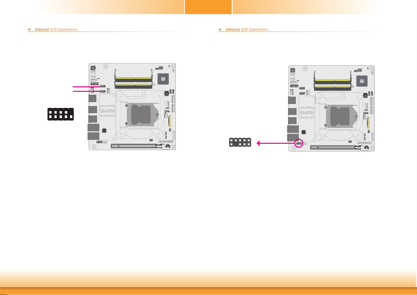
COM (Serial) Ports
COM 3
COM 4
RD
DSR
2
1 9
GND
RTS CTS
RI
TD DTR
DCD
COM 3, COM 4: RS232
COM 3 and COM 4 are RS232 serial ports.
The serial ports are asynchronous communication ports with 16C550A-compatible UARTs that
can be used with modems, serial printers, remote display terminals, and other serial devices.
Front Audio Connector
Line-R
Mic-R
GND
Line-L
9
10
Line-JD
Front Audio
The front audio connector allows you to connect to the line-out and mic-in jacks that are at
the front panel of your system.
Mic-JD
N.C.
Mic-L
1
2
GND
Front
Audio
Connecting External Serial Ports
Your COM port may come mounted on a card-edge bracket. Install the card-edge bracket to
an available slot at the rear of the system chassis then insert the serial port cable to the COM
connector. Make sure the colored stripe on the ribbon cable is aligned with pin 1 of the COM
connector.
BIOS Setting
Configure the serial COM ports in the Advanced menu (“SIO NUVOTON6106D” submenu) of
the BIOS. Refer to the chapter 3 for more information.
Chapter 2 Hardware Installation
Driver Installation
Install the audio driver. Refer to the chapter 4 for more information.
29
www.d.com
Page 30
Chapter 2
► Internal I/O Connectors
► Internal I/O Connectors
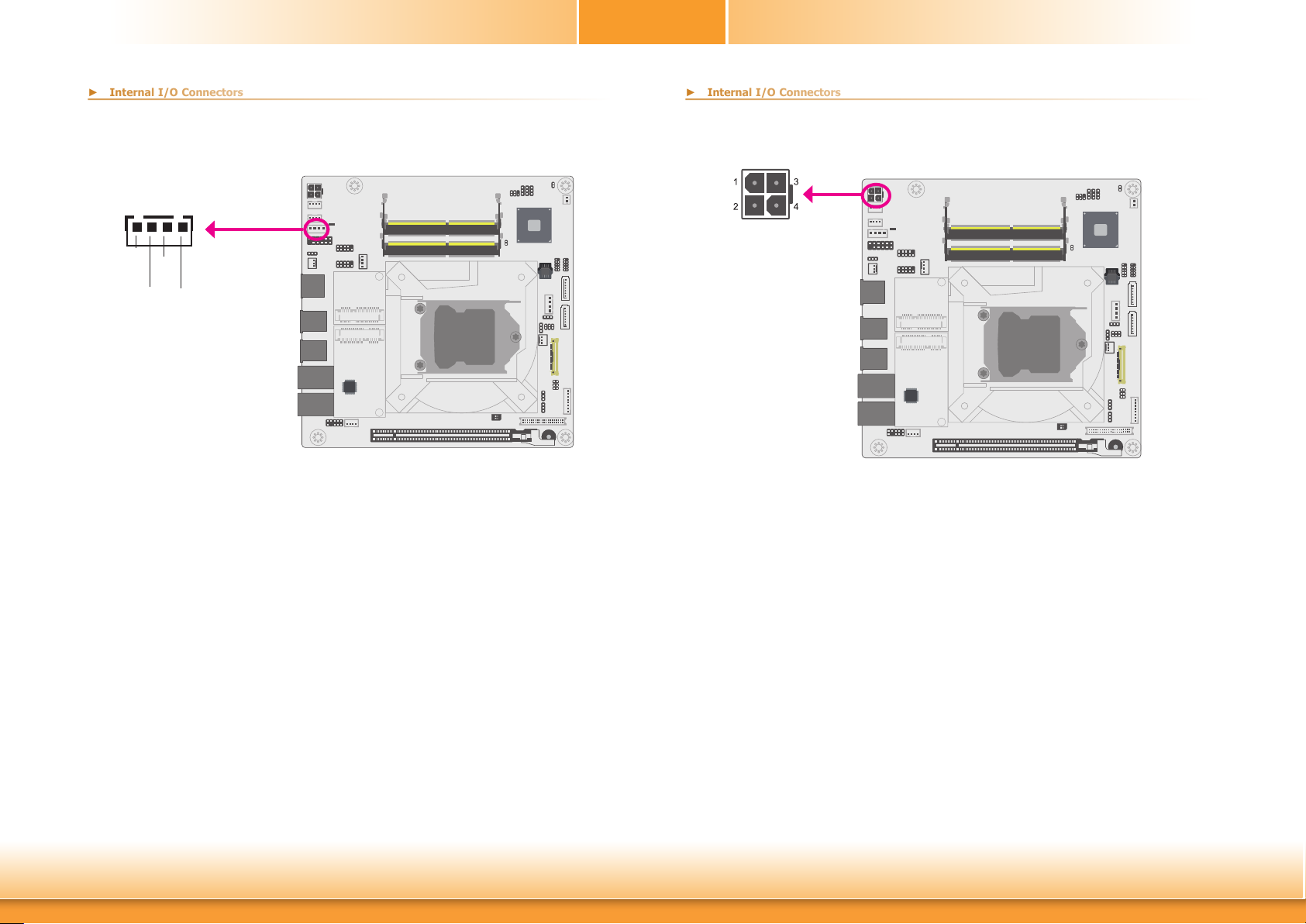
Power ATX Mode
1
GND
Control
5VSB
GND
Depending on customer’s power supply requirement and application, both CN18 and CN2 (DC-in)
have to be connected to supply power to the system.
CN18
15~36V DC-in
DC-in
(CN2)
This DC-in connector is a 4-pin vertical connector and is considered as a low power solution.
Connect a DC power cord to this connector. Using a voltage more than the recommended
range may fail to boot the system or cause damage to the system board.
Chapter 2 Hardware Installation
30
www.d.com
Page 31
Chapter 2
► Internal I/O Connectors
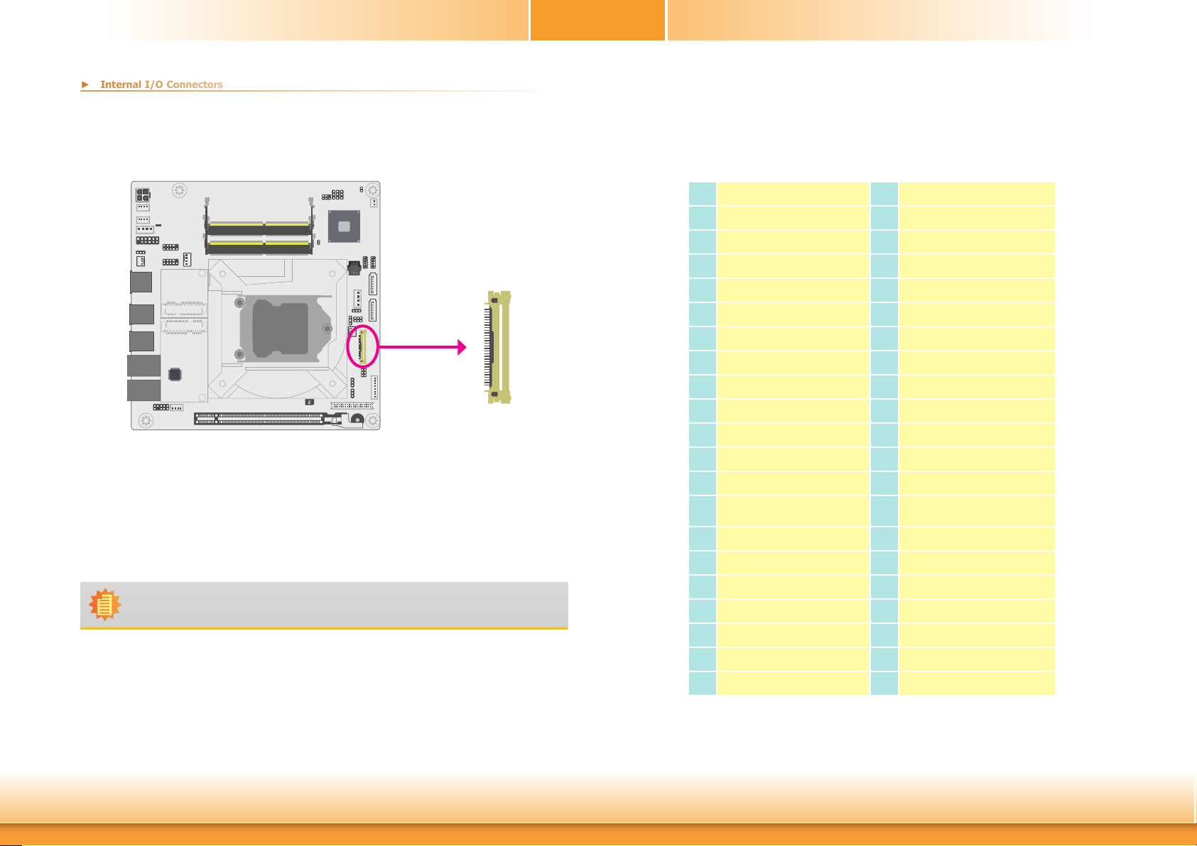
eDP Connector
eDP
1
The eDP connector is an embedded display port which has advanced power-saving features
to connect a display device to transmit digital communication of audio and video signals. The
table on the right side indicates the pin definitions of the eDP connector.
Note:
DFI board's eDP connector: I-PEX 20455-040E-76 (40 Pin, 90D, 0.5mm).
▼ eDP Pin Assignment
Pin Function Pin Function
NA
1
GND
2
eDP_LANE3-
3
eDP_LANE3+
4
GND
5
eDP_LANE2-
6
eDP_LANE2+
7
GND
8
eDP_LANE1-
9
eDP_LANE1+
10
GND
11
eDP_LANE0-
12
eDP_LANE0+
13
GND
14
eDP_AUX+
15
eDP_AUX-
16
GND
17
eDP Panel Power
18
eDP Panel Power
19
eDP Panel Power
20
eDP Panel Power
21
NA
22
GND
23
GND
24
GND
25
GND
26
eDP_HPD
27
GND
28
GND
29
GND
30
GND
31
eDP_Backlight On/O Control
32
eDP Inverter Brightness
33
Voltage Control
NA
34
NA
35
Inverter Power
36
Inverter Power
37
Inverter Power
38
Inverter Power
39
NA
40
Chapter 2 Hardware Installation
31
www.d.com
Page 32
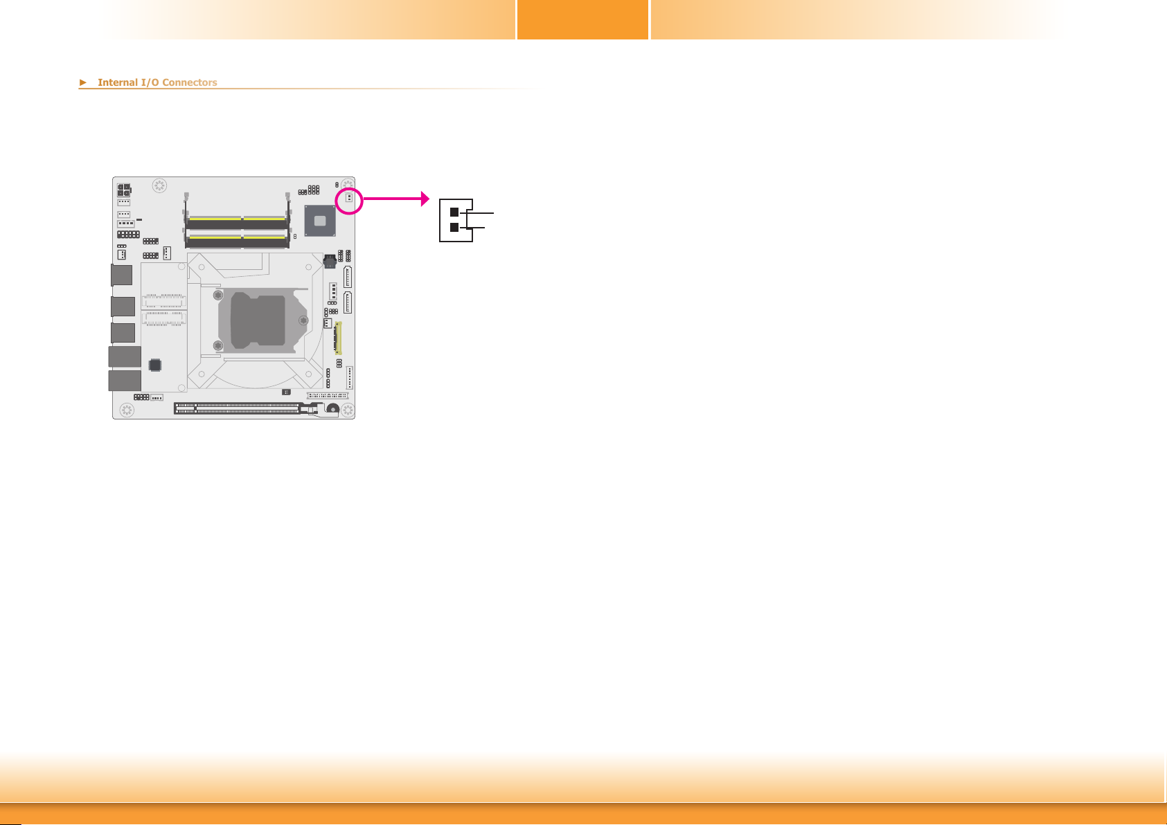
Battery
► Internal I/O Connectors
Battery
Chapter 2
1
2
+3.3V
GND
The lithium ion battery powers the real-time clock and CMOS memory. It serves as an auxiliary
source of power when the main power source is lost.
Safety Measures
• There exists explosion hazard if the battery is incorrectly installed.
• Replace only with the same or equivalent type recommended by the manufacturer.
• Dispose of used batteries according to local ordinances.
Chapter 2 Hardware Installation
32
www.d.com
Page 33
Chapter 3
Chapter 3 - BIOS Setup
► Overview
The BIOS is a program that takes care of the basic level of communication between the CPU
and peripherals. It contains codes for various advanced features found in this system board.
The BIOS allows you to configure the system and save the configuration in a battery-backed
CMOS so that the data retains even when the power is off. In general, the information stored
in the CMOS RAM of the EEPROM will stay unchanged unless a configuration change has been
made such as a hard drive replaced or a device added.
It is possible that the CMOS battery will fail causing CMOS data loss. If this happens, you need
to install a new CMOS battery and reconfigure the BIOS settings.
Note:
The BIOS is constantly updated to improve the performance of the system board;
therefore the BIOS screens in this chapter may not appear the same as the actual
one. These screens are for reference purpose only.
Default Configuration
Most of the configuration settings are either predefined according to the Load Optimal Defaults
settings which are stored in the BIOS or are automatically detected and configured without requiring any actions. There are a few settings that you may need to change depending on your
system configuration.
Entering the BIOS Setup Utility
The BIOS Setup Utility can only be operated from the keyboard and all commands are keyboard commands. The commands are available at the right side of each setup screen.
The BIOS Setup Utility does not require an operating system to run. After you power up the
system, the system logo appears on the screen and the memory count begins. After the
memory test, the message “Press DEL to run setup” will appear on the screen. If the message
disappears before you respond, restart the system or press the “Reset” button. You may also
restart the system by pressing the <Ctrl> <Alt> and <Del> keys simultaneously.
Legends
Keys Function
Right and Left arrows
Up and Down arrows
<Esc>
<F5>
<F6>
<F1>
<F9>
<F10>
<Enter>
Scroll Bar
When a scroll bar appears to the right of the setup screen, it indicates that there are more
available fields not shown on the screen. Use the up and down arrow keys to scroll through all
the available fields.
Submenu
When “” appears on the left of a particular field, it indicates that a submenu which contains
additional options are available for that field. To display the submenu, move the highlight to
that field and press <Enter>.
Move the cursor left or right to select a menu.
Moves the cursor up or down between submenu or elds.
Exit to the BIOS Setup Utility.
Next value/option of the highlighted eld
Previous value/option of the highlighted eldeld.
Display general help
Optimized defaults
Save and Exit
Enter the highlighted submenu
Chapter 3 BIOS Setup
33
www.d.com
Page 34
Chapter 3
► Main
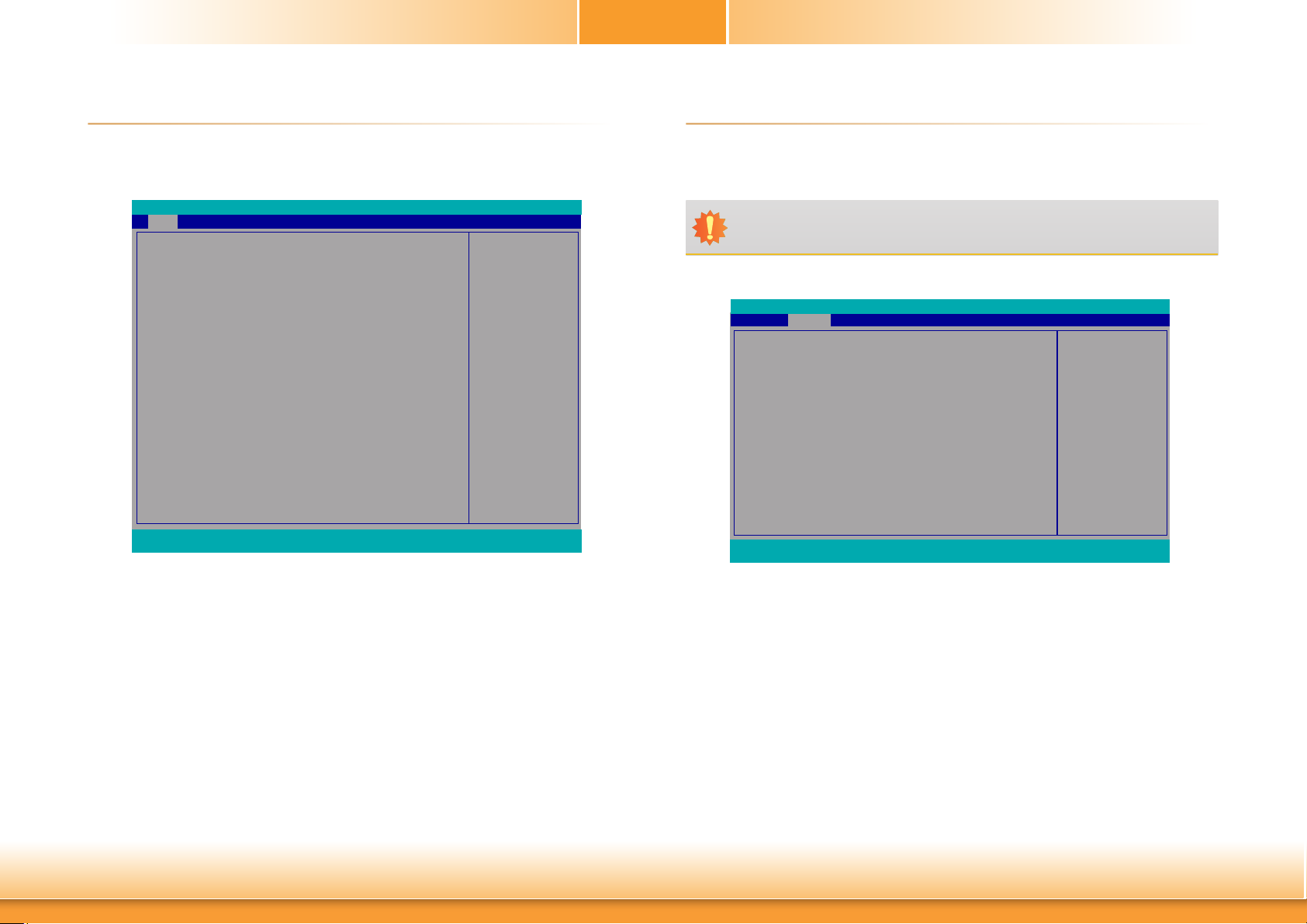
The Main menu is the first screen that you will see when you enter the BIOS Setup Utility.
Advanced Boot ExitMain
Project Name
BIOS Version
Supported Processor
Processor Type
CPUID
CPU Speed
CPU Stepping
L1 Data Cache
L1 Instruction Cache
L2 Cache
L3 Cache
Number Of Processors
Microcode Rev
Total Memory
System Memory Speed
DDR4_1
DDR4_2
PCH Rev / SKU
Intel ME Version / SKU
System Time
System Date
F1 Help ↑/↓ Select Item F5/F6 Change Values F9 Setup Defaults
Esc Exit ←/→ Select Item Enter Select SubMenu F10 Save and Exit
Security
InsydeH2O Setup Utility
SD106
B194.25A
Intel 6th and 7th Generation CPU
Genuine Intel(R) CPU 0000 @ 3.00GHz
0x506E8 (SKYLAKE DT HALO)
3000 MHz
08 (KBL A0 Stepping)
32 KB
32 KB
256 KB
8192 KB
4 Core(s) / 8 Thread(s)
00000034
4096 MB
2133 MHz
4096 MB
[Not Installed]
31 (D1 Stepping) / SKL PCH-H Q170
11.8.55.3510 / CORPORATE
[15:13:40]
[05/25/2019]
This is the help for the
hour, minute, second eld.
Valid range is from 0 to
23, 0 to 59, 0 to 59. INCREASE/REDUCE: +/-.
Rev. 5.0
► Advanced
The Advanced menu allows you to configure your system for basic operation. Some entries are
defaults required by the system board, while others, if enabled, will improve the performance
of your system or let you set some features according to your preference.
Important:
Setting incorrect field values may cause the system to malfunction.
Main Advanced
ACPI Conguration
CPU Conguration
Video Conguration
Audio Conguration
SATA Conguration
USB Conguration
PCI Express Conguration
ME Conguration
Active Management Technology Support
MEBX Conguration
Debug Conguration
Device Manager
SIO NUVOTON6106D
Console Redirection
F1 Help ↑/↓ Select Item F5/F6 Change Values F9 Setup Defaults
Esc Exit ←/→ Select Item Enter Select SubMenu F10 Save and Exit
Security Boot Exit
InsydeH2O Setup Utility
ACPI Conguration Setting
Rev. 5.0
System Time
The time format is <hour>, <minute>, <second>. The time is based on the 24-hour militarytime clock. For example, 1 p.m. is 13:00:00. Hour displays hours from 00 to 23. Minute displays minutes from 00 to 59. Second displays seconds from 00 to 59.
System Date
The date format is <month>, <date>, <year>. Month displays the month, from 01 to 12.
Date displays the date, from 01 to 31. Year displays the year, from 2000 to 2099.
Chapter 3 BIOS Setup
34
www.d.com
Page 35
ACPI Configuration
► Advanced
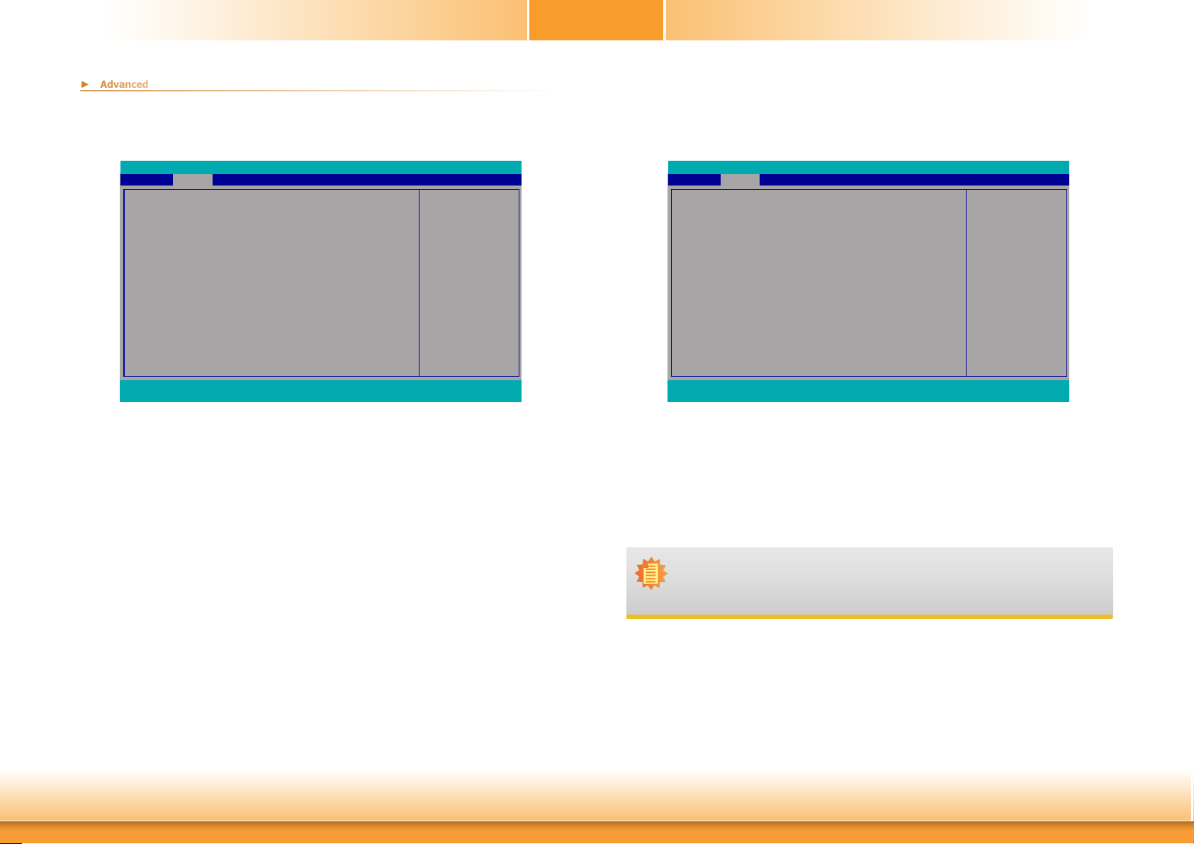
This section is used to configure the system ACPI parameters.
Chapter 3
Advanced
ACPI Conguration
Wake On LAN <Disabled>
After G3 <Always On>
Wake On RTC <Disabled>
F1 Help ↑/↓ Select Item F5/F6 Change Values F9 Setup Defaults
Esc Exit ←/→ Select Item Enter Select SubMenu F10 Save and Exit
InsydeH2O Setup Utility Rev. 5.0
Determines the action taken when the system power
is off and a PCI Power
Management Enable wake
up event occurs.
Wake On LAN
This field is used to enable or disable the LAN signal to wake up the system.
After G3
This field is to specify what state to go when power is re-applied after a power failure (G3
state).
Always On The system working state.
Always Off Off, except for trickle current to devices such as the power button.
Wake On RTC
Automatically power the system on at a particular time every day from the Real-time clock
battery.
Advanced
ACPI Conguration
Wake On LAN <Disabled>
After G3 <Always On>
BGRT Logo <Enabled>
Wake On RTC <Disabled>
F1 Help ↑/↓ Select Item F5/F6 Change Values F9 Setup Defaults
Esc Exit ←/→ Select Item Enter Select SubMenu F10 Save and Exit
InsydeH2O Setup Utility Rev. 5.0
Support display logo with
ACPI BGRT table.
BGRT Logo
This field is used to enable or disable to support display logo with ACPI BGRT table.
Note:
Under Dual Boot Type or UEFI Boot Type mode, if Quiet Boot is set to enabled,
BGRT Logo field will appear for configuration. Refer to the Boot menu for more
information.
Wake up time
When Wake On RTC is set to enabled, specify the wake up time of the day: <hour> (00~23),
<minute> (00~59), <second> (00~59).
Chapter 3 BIOS Setup
35
www.d.com
Page 36
Chapter 3
► Advanced
► Advanced
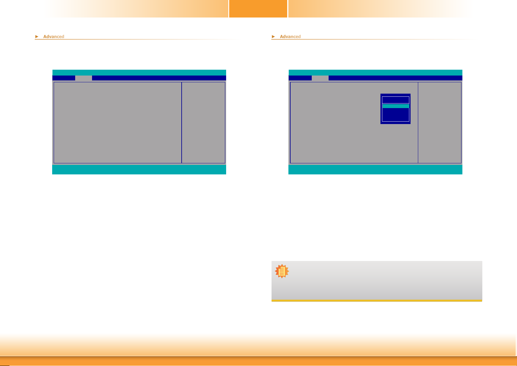
CPU Configuration
This section is used to configure the CPU.
Advanced
CPU Conguration
Intel Speed Step <Enabled>
Turbo Mode <Enabled>
CPU C States <Enabled>
Hyper-Threading <Enabled>
F1 Help ↑/↓ Select Item F5/F6 Change Values F9 Setup Defaults
Esc Exit ←/→ Select Item Enter Select SubMenu F10 Save and Exit
InsydeH2O Setup Utility Rev. 5.0
Allows more than two fre-
quency ranges to be supported.
Intel Speed Step
This field is used to enable or disable the Intel Enhanced SpeedStep Technology. If enabled,
Turbo Mode will appear for configuration.
Turbo Mode
Enable or disable the turbo mode.
CPU C States
Enable or disable the CPU Power Management.
Video Configuration
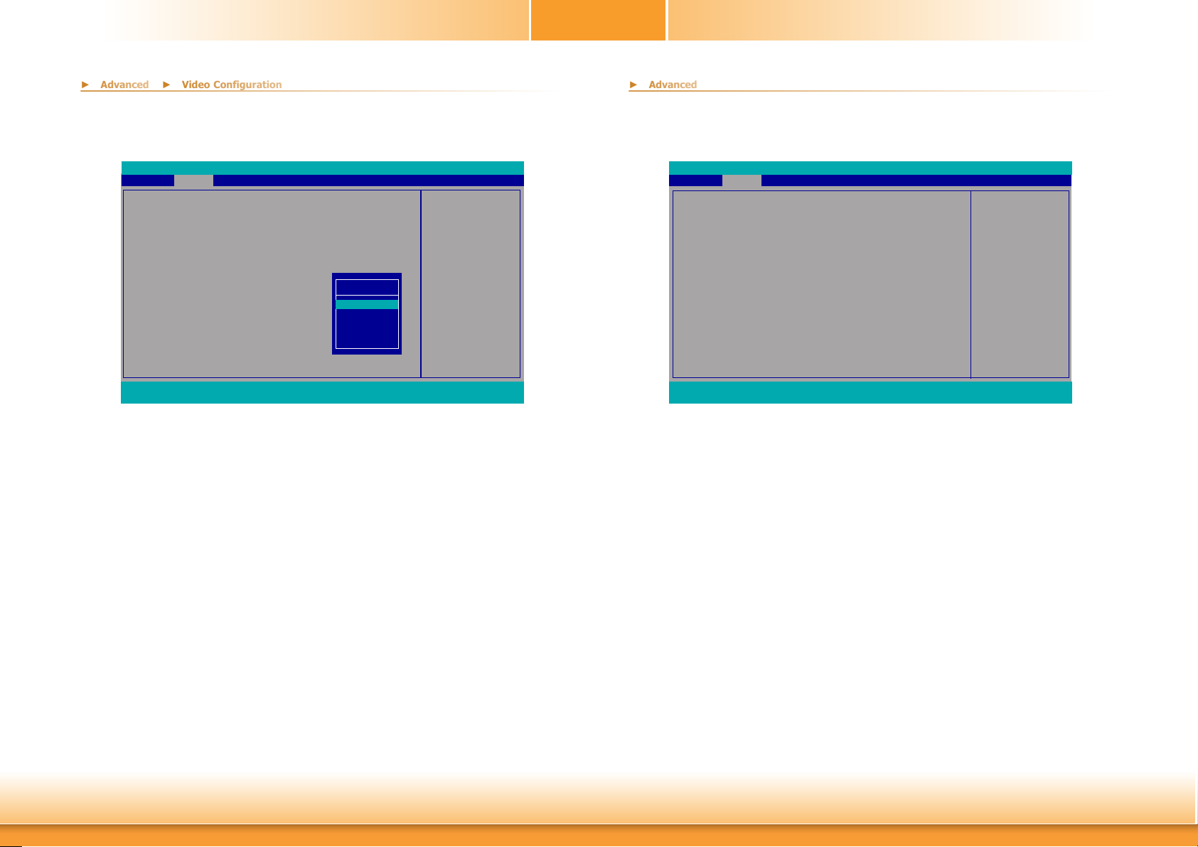
This section configures the video settings.
Advanced
Video Conguration
Primary Display
Internal Graphics Device
Boot display
PTN3460 Conguration
LCD Panel Type
F1 Help ↑/↓ Select Item F5/F6 Change Values F9 Setup Defaults
Esc Exit ←/→ Select Item Enter Select SubMenu F10 Save and Exit
InsydeH2O Setup Utility Rev. 5.0
<Auto>
<Auto>
<Auto>
<24 Bit>
<1024x768>
Primary Display
Auto
IGFX
PEG
PCI
Primary Display
Set the initial priority.
Internal Graphics Device
Keep IGFX enabled or disabled based on the setup options.
Boot display
Set the display device combination.
Initial priority:
AUTO: PEG->PCIe->PCI
->IGFX
IGFX: IGFX->PEG->
PCIe->PCI
PEG: PEG->PCIe->PCI->
IGFX
PCI: PCI->PCIe->PEG->
IGFX
Hyper-Threading
Enables this field for Windows XP and Linux which are optimized for Hyper-Threading technology. Select disabled for other OSes not optimized for Hyper-Threading technology. When disabled, only one thread per enabled core is enabled.
Chapter 3 BIOS Setup
Note:
To control "Primary Display" & "Boot display", first go to "Boot" menu and select
different "Boot Type".
Boot Type : Legacy Boot Type -> Hide Primary Display & Show Boot display
Boot Type : UEFI Boot Type -> Show Primary Display & Hide Boot display
Boot Type : Dual Boot Type -> Show Primary Display & Show Boot display
36
www.d.com
Page 37
Chapter 3
► Advanced
► Video Configuration
► Advanced
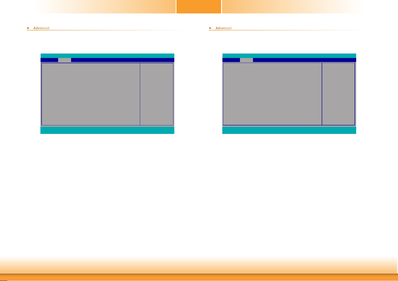
Audio Configuration
This section is used to configure the audio settings.
Advanced
Video Conguration
Primary Display
Internal Graphics Device
Boot display
PTN3460 Conguration
LCD Panel Type
F1 Help ↑/↓ Select Item F5/F6 Change Values F9 Setup Defaults
Esc Exit ←/→ Select Item Enter Select SubMenu F10 Save and Exit
InsydeH2O Setup Utility Rev. 5.0
Choose display device
<Auto>
<Auto>
<Auto>
<24 Bit>
<1024x768>
Boot display
Auto
eDP + LVDS
eDP + DP
LVDS + DP
DP + LVDS
combination
PTN3460 Configuration
Select the LCD panel color depth: 18 Bit, 24 Bit, 36 Bit or 48 Bit.
LCD Panel Type
Please check the specifications of your LCD monitor. Select the type of LCD panel connected
to the system’s LCD connector: VBIOS Default, 800x480, 800x600, 1024x768, 1366x768,
1280x1024 or 1920x1080.
Advanced
Audio Conguration
HD Audio
F1 Help ↑/↓ Select Item F5/F6 Change Values F9 Setup Defaults
Esc Exit ←/→ Select Item Enter Select SubMenu F10 Save and Exit
InsydeH2O Setup Utility
<Enabled>
HD Audio
Control the detection of the HD-Audio device.
Disabled HDA will be unconditionally disabled.
Enabled HDA will be unconditionally enabled.
Auto HDA will be enabled if present, disabled otherwise.
Rev. 5.0
Control Detection of the
HD-Audio device.
Disabled = HDA will be
unconditionally disabled
Enabled = HDA will be
unconditionally enabled
Auto = HDA will be enabled if present, disabled
otherwise.
Chapter 3 BIOS Setup
37
www.d.com
Page 38
Chapter 3
► Advanced
► Advanced
SATA Configuration
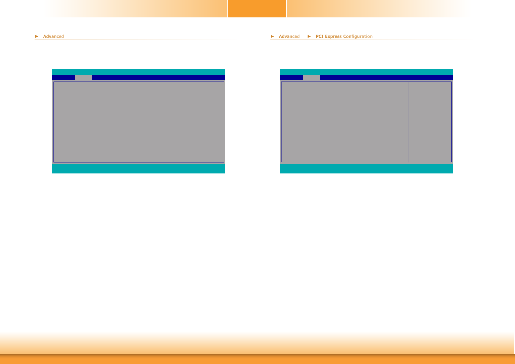
This section is designed to select the SATA controller and the type of hard disk drive which are
installed in your system unit.
Advanced
SATA Conguration
SATA Controller(s)
SATA Speed
SATA Mode Selection
SATA3_0
Port 0
Hot Plug
MINI PCIE (CN10)
Port 1
Hot Plug
MINI PCIE (CN11)
Port 2
Hot Plug
SATA3_3
Port 3
Hot Plug
F1 Help ↑/↓ Select Item F5/F6 Change Values F9 Setup Defaults
Esc Exit ←/→ Select Item Enter Select SubMenu F10 Save and Exit
InsydeH2O Setup Utility Rev. 5.0
Enable/Disable SATA
<Enabled>
<Auto>
<AHCI>
Empty
<Enabled>
<Disabled>
Empty
<Enabled>
<Disabled>
Empty
<Enabled>
<Disabled>
Empty
<Enabled>
<Disabled>
Device.
SATA Controller(s)
This field is used to enable or disable Serial ATA devices.
SATA Speed
This field is used to select SATA speed generation limit: Auto, Gen1, Gen2 or Gen3.
SATA Mode Selection
The mode selection determines how the SATA controller(s) operates.
USB Configuration
This section is used to configure the parameters of the USB device.
Advanced
USB Conguration
Legacy USB Support
XHCI Hand-o
F1 Help ↑/↓ Select Item F5/F6 Change Values F9 Setup Defaults
Esc Exit ←/→ Select Item Enter Select SubMenu F10 Save and Exit
InsydeH2O Setup Utility Rev. 5.0
USB keyboard/mouse/storage support under UEFI
<Enabled>
<Disabled>
and DOS environment. It
will supporting UEFI en-
vironment only if set to
UEFI only.
Legacy USB Support
Disabled Disable USB keyboard/mouse/storage support under UEFI and DOS environment.
Enabled Enable USB keyboard/mouse/storage support under UEFI and DOS environment.
UEFI Only Enable USB keyboard/mouse/storage support under UEFI environment.
XHCI Hand-off
Enable or disable to clear XHCI controller ownership change SMI bit by BIOS.
AHCI This option allows the Serial ATA devices to use AHCI (Advanced Host Controller
Interface).
RAID This option allows you to create RAID or Intel Matrix Storage configuration on Se-
rial ATA devices.
Port 0, 1, 2, 3 and Hot Plug
These fields are used to enable or disable the serial ATA port and its hot plug.
Chapter 3 BIOS Setup
38
www.d.com
Page 39
Chapter 3
► Advanced
► Advanced
► PCI Express Configuration
PCI Express Configuration
This section configures settings relevant to PCI Express root ports.
Advanced
PCI Express Conguration
PCIE 1
LAN1
LAN2
Half size mini PCIE
Full size mini PCIE
F1 Help ↑/↓ Select Item F5/F6 Change Values F9 Setup Defaults
Esc Exit ←/→ Select Item Enter Select SubMenu F10 Save and Exit
InsydeH2O Setup Utility Rev. 5.0
PEG PCI Express Port
setting
PCIE 1/LAN1/LAN2/Half size mini PCIE/Full size mini PCIE
This field is used to enable or disable the PCI Express Root Port.
Advanced
PCIE 1
PCIe Speed
Hot Plug
F1 Help ↑/↓ Select Item F5/F6 Change Values F9 Setup Defaults
Esc Exit ←/→ Select Item Enter Select SubMenu F10 Save and Exit
InsydeH2O Setup Utility Rev. 5.0
<Enabled>
<AUTO>
<Disabled>
Enable or Disable the Root
Port
PCIe Speed
Select the speed of the PCI Express Root Port: Auto, Gen1, Gen2 or Gen3.
Hot Plug
This field is used to enable or disable the PCI Express Hot Plug.
Chapter 3 BIOS Setup
39
www.d.com
Page 40
Chapter 3
► Advanced
► Advanced
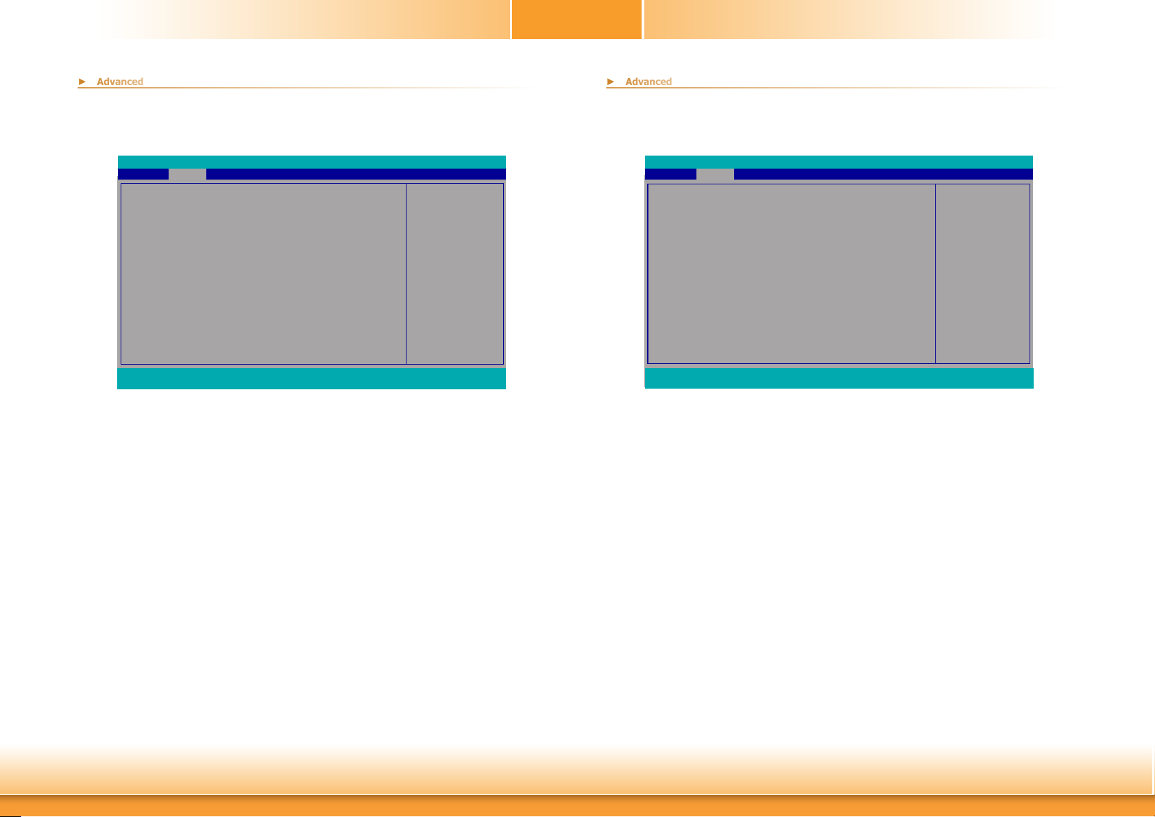
ME Configuration
This section configures settings relevant to flash ME region.
Advanced
ME Conguration
Me Fw Image Re-Flash
F1 Help ↑/↓ Select Item F5/F6 Change Values F9 Setup Defaults
Esc Exit ←/→ Select Item Enter Select SubMenu F10 Save and Exit
InsydeH2O Setup Utility Rev. 5.0
<Disabled>
Me Fw Image Re-Flash
This field is used to enable or disable the flash ME region.
Enable/disable to ash ME
region
Active Management Technology Support
The section allows users to enable or disable the Intel® Active Management Technology (Intel®
AMT). Please refer to Chapter 6 for more information.
Advanced
Active Management Technology Support
Intel AMT Support <Enabled>
Un-Congure ME <Disabled>
F1 Help ↑/↓ Select Item F5/F6 Change Values F9 Setup Defaults
Esc Exit ←/→ Select Item Enter Select SubMenu F10 Save and Exit
InsydeH2O Setup Utility Rev. 5.0
When disabled AMT
BIOS Features are no
longer supported and user
is no longer able to access
MEBx Setup.
Note :
This option does not dis-
able Manageability Features in FW.
Intel AMT Support
This field is used to enable or disable Intel® Active Management Technology.
Chapter 3 BIOS Setup
Un-Configure ME
This field is used to enable or disable to un-configure ME with resetting MEBX password to
default.
40
www.d.com
Page 41
Chapter 3
► Advanced
► Advanced
MEBX Configuration
Configure Intel® Active Management Technology (Intel® AMT) in the Intel® Management Engine
BIOS Extension (MEBX) setup menu. Please refer to Chapter 6 for more information.
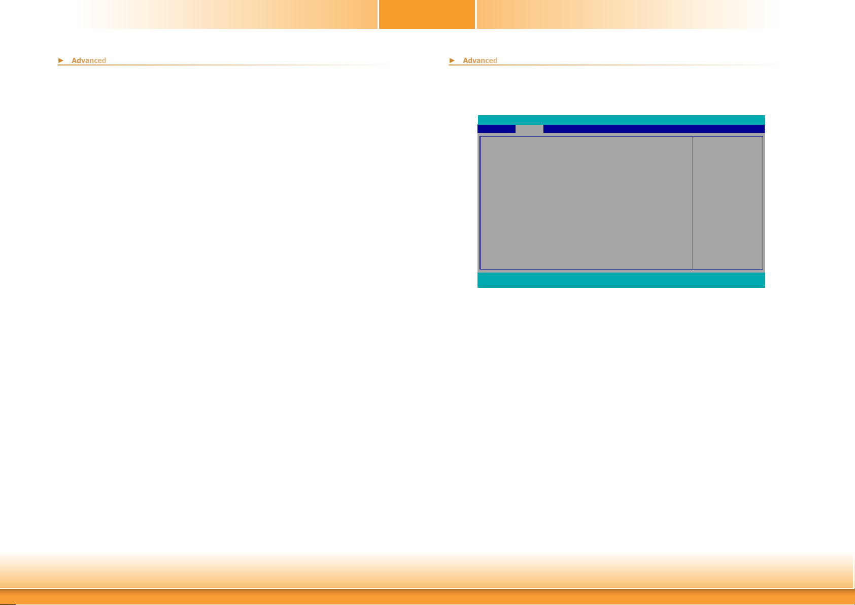
Debug Configuration
This section configures Debug setting.
Advanced
Debug Conguration
Dynamic EFI DEBUG <O>
F1 Help ↑/↓ Select Item F5/F6 Change Values F9 Setup Defaults
Esc Exit ←/→ Select Item Enter Select SubMenu F10 Save and Exit
InsydeH2O Setup Utility Rev. 5.0
Enable it to output debug
message from COM port.
Dynamic EFI DEBUG
This field is used to turn on or off the function to output debug message from COM port. If
set to on, relevant EFI debug configuration will show up.
Chapter 3 BIOS Setup
41
www.d.com
Page 42
Chapter 3
► Advanced
► Debug Configuration
► Advanced
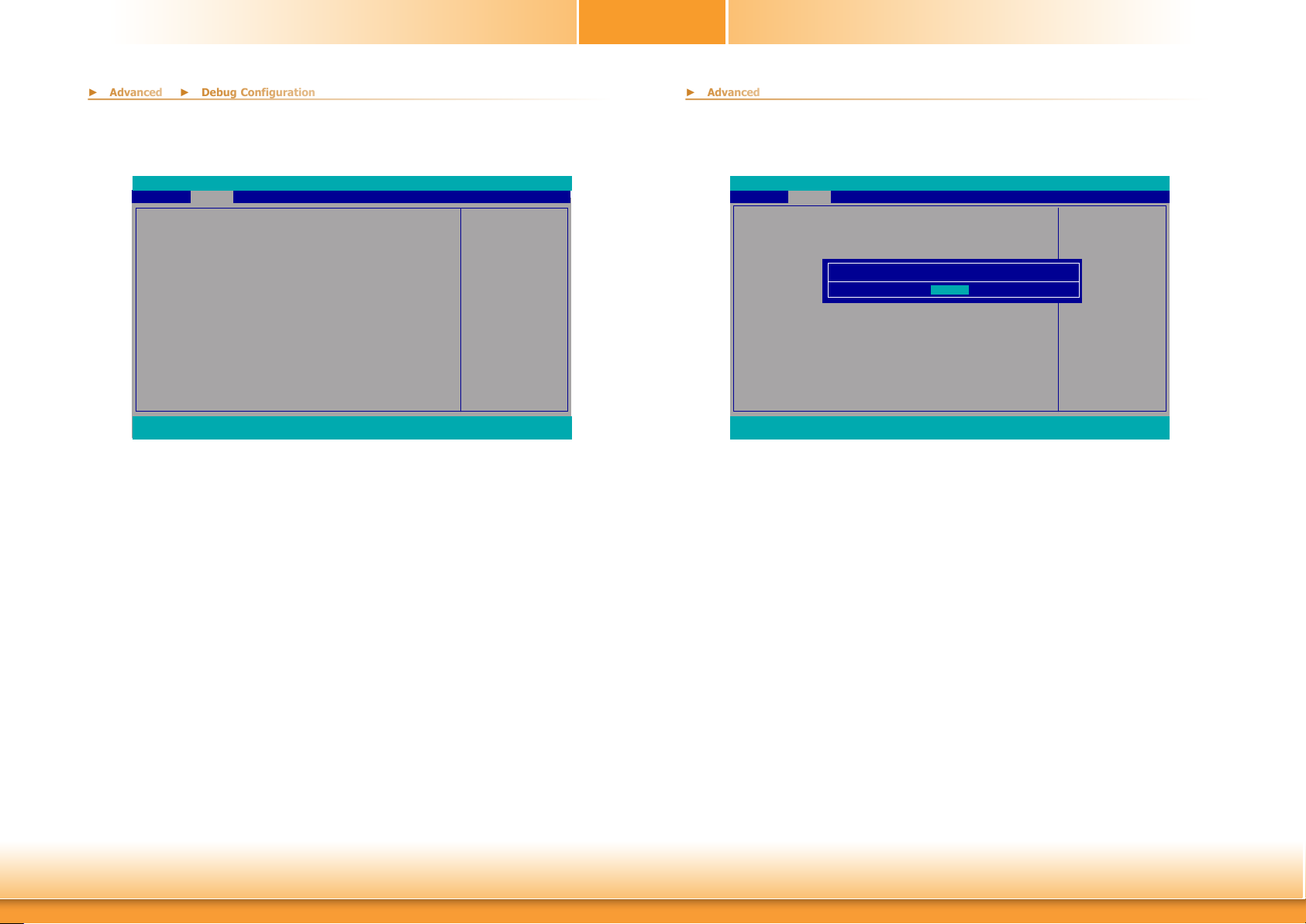
Device Manager
The section configures UEFI device with option ROM, such as LAN card, etc.
Advanced
Debug Conguration
Dynamic EFI DEBUG <On>
EFI debug print level [0x8000004F]
EFI debug serial port [0x3F8]
EFI debug baud rate [115200]
F1 Help ↑/↓ Select Item F5/F6 Change Values F9 Setup Defaults
Esc Exit ←/→ Select Item Enter Select SubMenu F10 Save and Exit
InsydeH2O Setup Utility Rev. 5.0
Enable it to output debug
message from COM port.
EFI debug print level
Enter numeric value for EFI Debug Print Level and default is 0x8000004F.
EFI debug serial port
Enter serial port to output EFI debug message and default is 0x3F8.
EFI debug baud rate
Enter baud rate to output EFI debug message and default is 115200.
Advanced
Device Manager
Device Manager
Exit BIOS Setup Utility and launch Device Manager !!
[OK]
F1 Help ↑/↓ Select Item F5/F6 Change Values F9 Setup Defaults
Esc Exit ←/→ Select Item Enter Select SubMenu F10 Save and Exit
InsydeH2O Setup Utility Rev. 5.0
Device Manager Setting
Chapter 3 BIOS Setup
42
www.d.com
Page 43
SIO NUVOTON6106D
► Advanced
Chapter 3
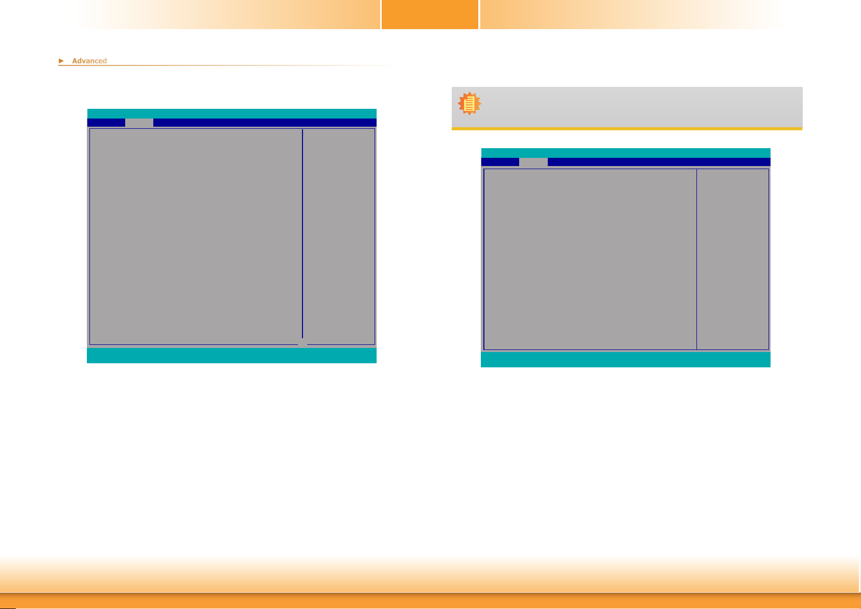
This section configures the system super I/O chip parameters.
Advanced
SYS Smart Fan Control
Boundary 1
Boundary 2
Boundary 3
Boundary 4
Fan Speed Count 1
Fan Speed Count 2
Fan Speed Count 3
Fan Speed Count 4
CPU Smart Fan Control
Boundary 1
Boundary 2
Boundary 3
Boundary 4
Fan Speed Count 1
Fan Speed Count 2
Fan Speed Count 3
Fan Speed Count 4
SYS Smart Fan 2 Control
Boundary 1
Boundary 2
Boundary 3
Boundary 4
Fan Speed Count 1
Fan Speed Count 2
Fan Speed Count 3
Fan Speed Count 4
COM Port 3
Base I/O Address
Interrupt
COM Port 4
Base I/O Address
Interrupt
WDT
F1 Help ↑/↓ Select Item F5/F6 Change Values F9 Setup Defaults
Esc Exit ←/→ Select Item Enter Select SubMenu F10 Save and Exit
InsydeH2O Setup Utility
<Enable>
[30]
[40]
[50]
[60]
[30]
[40]
[50]
[75]
<Enable>
[30]
[40]
[50]
[60]
[30]
[40]
[50]
[75]
<Enable>
[30]
[40]
[50]
[60]
[30]
[40]
[50]
[75]
<Enable>
<3F8>
<IRQ4>
<Enable>
<2F8>
<IRQ3>
<Disable>
Rev. 5.0
Enable/Disable Smart Fan
↓
Note:
When SYS Smart Fan Control, CPU Smart Fan Control, and SYS Smart Fan 2 Control are disabled, "Fix Fan Speed Count" will appear for configuration.
Advanced
SYS Smart Fan Control
Fix Fan Speed Count
CPU Smart Fan Control
Fix Fan Speed Count
SYS Smart Fan 2 Control
Fix Fan Speed Count
COM Port 3
Base I/O Address
Interrupt
COM Port 4
Base I/O Address
Interrupt
WDT
Case Open
PC Health Status
F1 Help ↑/↓ Select Item F5/F6 Change Values F9 Setup Defaults
Esc Exit ←/→ Select Item Enter Select SubMenu F10 Save and Exit
InsydeH2O Setup Utility
<Disable>
[50]
<Disable>
[50]
<Disable>
[50]
<Enable>
<3F8>
<IRQ4>
<Enable>
<2F8>
<IRQ3>
<Disable>
<Disable>
Rev. 5.0
SYS Smart Fan, CPU Smart Fan, SYS Smart Fan 2 Control
Enable or disable the system/CPU smart fan/fan 2.
Boundary 1 to Boundary 4
Set the boundary temperatures that determine the operation of the fan with different fan
speeds accordingly. For example, when the system or the CPU temperature reaches boundary temperature 1, the system or CPU fan should be turned on and operate at the designated
speed. The range is from 0-127oC.
Fan Speed Count 1 to Fan Speed Count 4
Set the fan speed. The range is from 1-100% (full speed).
Chapter 3 BIOS Setup
43
www.d.com
Page 44
Chapter 3
► Advanced
► Advanced
► SIO NUVOTON6106D
► SIO NUVOTON6106D
PC Health Status
This section displays the PC health status.
Advanced
Boundary 2
Boundary 3
Boundary 4
Fan Speed Count 1
Fan Speed Count 2
Fan Speed Count 3
Fan Speed Count 4
CPU Smart Fan Control
Boundary 1
Boundary 2
Boundary 3
Boundary 4
Fan Speed Count 1
Fan Speed Count 2
Fan Speed Count 3
Fan Speed Count 4
SYS Smart Fan 2 Control
Boundary 1
Boundary 2
Boundary 3
Boundary 4
Fan Speed Count 1
Fan Speed Count 2
Fan Speed Count 3
Fan Speed Count 4
COM Port 3
Base I/O Address
Interrupt
COM Port 4
Base I/O Address
Interrupt
WDT
Case Open
PC Health Status
F1 Help ↑/↓ Select Item F5/F6 Change Values F9 Setup Defaults
Esc Exit ←/→ Select Item Enter Select SubMenu F10 Save and Exit
InsydeH2O Setup Utility
[40]
[50]
[60]
[30]
[40]
[50]
[75]
<Enable>
[30]
[40]
[50]
[60]
[30]
[40]
[50]
[75]
<Enable>
[30]
[40]
[50]
[60]
[30]
[40]
[50]
[75]
<Enable>
<3F8>
<IRQ4>
<Enable>
<2F8>
<IRQ3>
<Disable>
<Disable>
COM Port 3/4
Configure the settings to use the serial port.
Rev. 5.0
↑
PC Health Status
Voltage
VBAT
VCORE
VDDQ
5V
+12V
Temperature
System (oC/oF)
CPU (oC/oF)
Fan Speed
SYS FAN
CPU FAN
SYS FAN 2
F1 Help ↑/↓ Select Item F5/F6 Change Values F9 Setup Defaults
Esc Exit ←/→ Select Item Enter Select SubMenu F10 Save and Exit
Advanced
InsydeH2O Setup Utility Rev. 5.0
3.072 V
0.784 V
1.184 V
4.939 V
11.616 V
35.0 C/ 95.0 F
42.0 C/ 107.6 F
0 RPM
0 RPM
0 RPM
Disable No configuration
Enable User configuration
WDT
Enable or disable the watchdog function. A counter will appear if you select to enable WDT.
Input any value between 1 to 255 seconds.
Case Open
Enable or disable the case open detection function.
Chapter 3 BIOS Setup
44
www.d.com
Page 45
Console Redirection
► Advanced
Chapter 3
This section configures settings relevant to console redirection.
Advanced
Console Redirection Setup
Console Serial Redirect
F1 Help ↑/↓ Select Item F5/F6 Change Values F9 Setup Defaults
Esc Exit ←/→ Select Item Enter Select SubMenu F10 Save and Exit
InsydeH2O Setup Utility Rev. 5.0
Enable Console Redirec-
<Disabled>
tion Function
Console Serial Redirect
This field is used to enable or disable the console serial redirection function.
When Console Serial Redirect is set to enabled, the screen will appear like below:
Advanced
Console Redirection Setup
Console Serial Redirect
Terminal Type
Baud Rate
Data Bits
Parity
Stop Bits
Flow Control
COM3
Enable VT-100, 115200, N81
COM4
Disable VT-100, 115200, N81
F1 Help ↑/↓ Select Item F5/F6 Change Values F9 Setup Defaults
Esc Exit ←/→ Select Item Enter Select SubMenu F10 Save and Exit
InsydeH2O Setup Utility
<Enabled>
<VT_100>
<115200>
<8 Bits>
<None>
<1 Bit>
<None>
Enable Console Redirection Function
Terminal Type
Select terminal type: VT_100, VT_100+, VT_UTF8 or PC_ANSI.
Baud Rate
Select baud rate: 115200, 57600, 38400, 19200, 9600, 4800, 2400 or 1200.
Rev. 5.0
Chapter 3 BIOS Setup
Data Bits
Select data bits: 7 bits or 8 bits.
Parity
Select parity bits: none, even or odd.
Stop Bits
Select stop bits: 1 bit or 2 bits.
Flow Control
Select flow control type: none, RTS/CTS or XON/XOFF.
45
www.d.com
Page 46
COM3/4
► Advanced
► Console Redirection
Chapter 3
When UseGlobalSetting is set to disabled, the screen will appear like below:
Advanced
PortEnable
UseGlobalSetting
F1 Help ↑/↓ Select Item F5/F6 Change Values F9 Setup Defaults
Esc Exit ←/→ Select Item Enter Select SubMenu F10 Save and Exit
InsydeH2O Setup Utility Rev. 5.0
<Enabled>
<Enabled>
PortEnable
This field is used to enable or disable the COM port to redirect the console.
UseGlobalSetting
This field is to enable or disable to use global setting. When enabled the global setting, setting
of the COM port will be the same as those in Console Redirection section. When disabled the
global setting, setting of the COM port can be configured independently in this section.
Advanced
PortEnable
UseGlobalSetting
Terminal Type
Baud Rate
Data Bits
Parity
Stop Bits
Flow Control
F1 Help ↑/↓ Select Item F5/F6 Change Values F9 Setup Defaults
Esc Exit ←/→ Select Item Enter Select SubMenu F10 Save and Exit
InsydeH2O Setup Utility Rev. 5.0
<Enabled>
<Disabled>
<VT_100>
<115200>
<8 Bits>
<None>
<1 Bit>
<None>
Chapter 3 BIOS Setup
46
www.d.com
Page 47
Chapter 3
► Security
Main Advanced
Current TPM Device
TPM State
TPM Availability
TPM Operation
Clear TPM
Supervisor Password
Set Supervisor Password
F1 Help ↑/↓ Select Item F5/F6 Change Values F9 Setup Defaults
Esc Exit ←/→ Select Item Enter Select SubMenu F10 Save and Exit
Security Boot Exit
TPM Availability
Set the TPM availability.
TPM Operation
Select one of the supported operation to change TPM2 state.
Clear TPM
Remove all TPM context associated with a specific owner.
InsydeH2O Setup Utility
<TPM 2.0 (DTPM)>
All Hierarchies Enabled, Owned
<Available>
<No Operation>
[ ]
Not installed
TMP Availability
Available
Hidden
Rev. 5.0
When Hidden, don’t exposes TPM to 0
► Boot
Main Advanced
Numlock
Boot Type
Network Stack
PXE Boot capability
USB Boot
Quiet Boot
Secure Boot Cong
F1 Help ↑/↓ Select Item F5/F6 Change Values F9 Setup Defaults
Esc Exit ←/→ Select Item Enter Select SubMenu F10 Save and Exit
Security Exit
InsydeH2O Setup Utility
Boot
<O>
<Dual Boot Type>
<Disabled>
<Disabled>
<Enabled>
<Disabled>
Selects Power-on state for
Numlock
Numlock
Select the power-on state for numlock.
Boot Type
Select the boot type. The options are UEFI Boot Type, Legacy Boot Type or Dual Boot
Type.
If you select “UEFI Boot Type” or “Dual Boot Type”, the “Network Stack”, “PXE Boot
capability”, “USB Boot” and “Quiet Boot” will show up.
Rev. 5.0
Set Supervisor Password
Set the supervisor’s password and the length of the password must be greater than
one character.
Chapter 3 BIOS Setup
If you select “Legacy Boot Type”, “PXE Boot to LAN”, “USB Boot” and “Quiet Boot” will
show up.
Note:
If the boot type is set to UEFI, the method for RAID volume creation will be differ-
ent. Please refer to Chapter 5 ˗ RAID for more information.
Network Stack
This field is used to enable or disable network stack.
PXE Boot capability
Disabled Suppoort Network Stack
UEFI IPv4/IPv6
Legacy Legacy PXE OPROM only
47
www.d.com
Page 48
Chapter 3
► Boot
PXE Boot to LAN
Disable or enable PXE boot to LAN.
USB Boot
Enable or disable booting to USB boot devices.
Quiet Boot
Enable or disable booting in text mode.
Secure Boot Config
User can choose to enable UEFI secure boot and restore factory default key or clear all secure
boot key.
InsydeH2O Setup Utility Rev. 5.0
Boot
Secure Boot
Platform Key
Pending Action
Clear Secure Boot Keys
Load Factory Default Key
<Disabled>
Not Enrolled
None
<Disabled>
<Disabled>
► Exit
Main Advanced
Exit Saving Changes
Load Optimal Defaults
Discard Changes
F1 Help ↑/↓ Select Item F5/F6 Change Values F9 Setup Defaults
Esc Exit ←/→ Select Item Enter Select SubMenu F10 Save and Exit
Security Boot
InsydeH2O Setup Utility
Exit
Exit system setup and save
your changes.
Exit Saving Changes
Select Yes and then press <Enter> to exit the system setup and save your changes.
Rev. 5.0
F1 Help ↑/↓ Select Item F5/F6 Change Values F9 Setup Defaults
Esc Exit ←/→ Select Item Enter Select SubMenu F10 Save and Exit
Chapter 3 BIOS Setup
Load Optimal Defaults
Select YES and then press <Enter> to load optimal defaults.
Discard Changes
Select YES and then press <Enter> to exit the system setup without saving your
changes.
48
www.d.com
Page 49

Chapter 3
► Updating the BIOS
To update the BIOS, you will need the new BIOS file and a flash utility. Please contact technical support or your sales representative for the files and specific instructions about how to update BIOS with the flash utility. For updating Insyde BIOS in UEFI mode, you may refer to the
how-to video at https://www.dfi.com/tw/knowledge/video/31.
► Notice: BIOS SPI ROM
1. The Intel® Management Engine has already been integrated into this system board. Due
to the safety concerns, the BIOS (SPI ROM) chip cannot be removed from this system
board and used on another system board of the same model.
2. The BIOS (SPI ROM) on this system board must be the original equipment from the factory and cannot be used to replace one which has been utilized on other system boards.
3. If you do not follow the methods above, the Intel® Management Engine will not be updated and will cease to be effective.
Note:
a. You can take advantage of flash tools to update the default configuration of the
BIOS (SPI ROM) to the latest version anytime.
b. When the BIOS IC needs to be replaced, you have to populate it properly onto
the system board after the EEPROM programmer has been burned and follow the
technical person's instructions to confirm that the MAC address should be burned
or not.
Chapter 3 BIOS Setup
49
www.d.com
Page 50
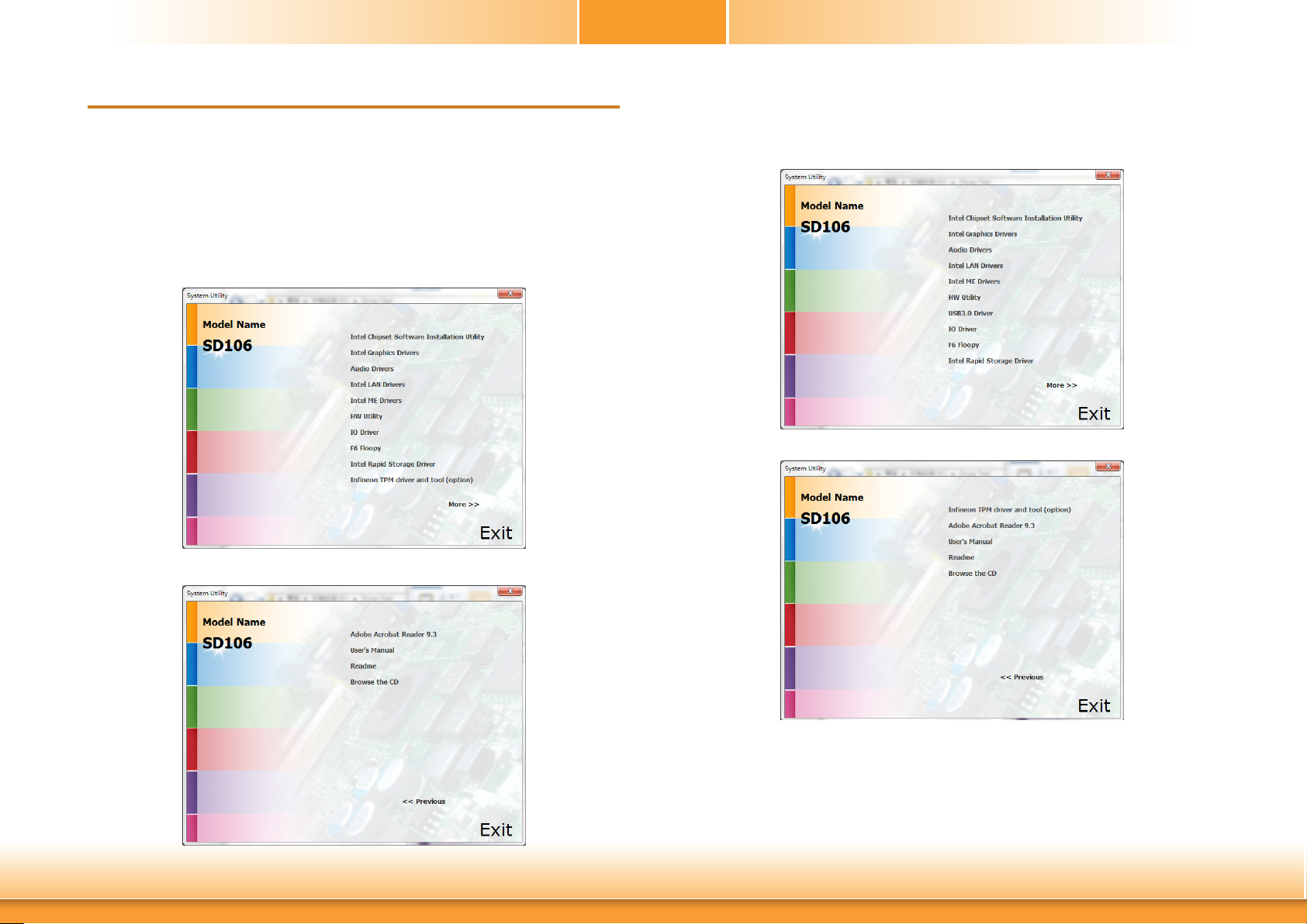
Chapter 4 - Supported Software
Chapter 4
The DVD that came with the system board contains drivers, utilities and software applications
required to enhance the performance of the system board.
Insert the DVD into a DVD-ROM drive. The autorun screen (Mainboard Utility DVD) will appear.
If after inserting the DVD, “Autorun” did not automatically start (which is, the Mainboard Utility
DVD screen did not appear), please go directly to the root directory of the DVD and doubleclick “Setup”.
► Auto-run Menu
For Windows 10
For Windows 8.1
Chapter 4 Supported Software
50
www.d.com
Page 51
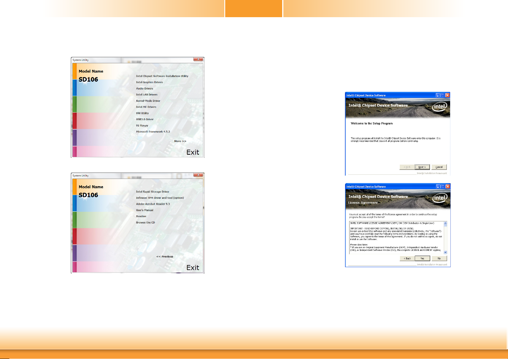
For Windows 7
Chapter 4
► Intel Chipset Software Installation Utility
The Intel Chipset Software Installation Utility is used for updating Windows® INF files so that
the Intel chipset can be recognized and configured properly in the system.
To install the utility, click “Intel Chipset Software Installation Utility” on the main menu.
1. Setup is ready to install the
utility. Click Next.
Chapter 4 Supported Software
2. Read the license agreement
then click Yes.
51
www.d.com
Page 52

3. Go through the readme
document for more installation tips then click Next.
4. Click Finish to exit setup.
Chapter 4
► Intel Graphics Drivers
To install the driver, click “Intel Graphics Drivers” on the main menu.
1. Setup is now ready to
install the graphics driver.
Click Next.
By default, the “Automatically run WinSAT and enable the Windows Aero
desktop theme” is enabled. With this enabled, after installing the graphics
driver and the system rebooted, the screen will turn blank for 1 to 2 minutes
(while WinSAT is running) before the Windows 7/Windows 8.1/Windows 10
desktop appears. The “blank screen” period is the time Windows is testing
the graphics performance.
Chapter 4 Supported Software
2. Read the license agreement
then click Yes.
52
www.d.com
Page 53
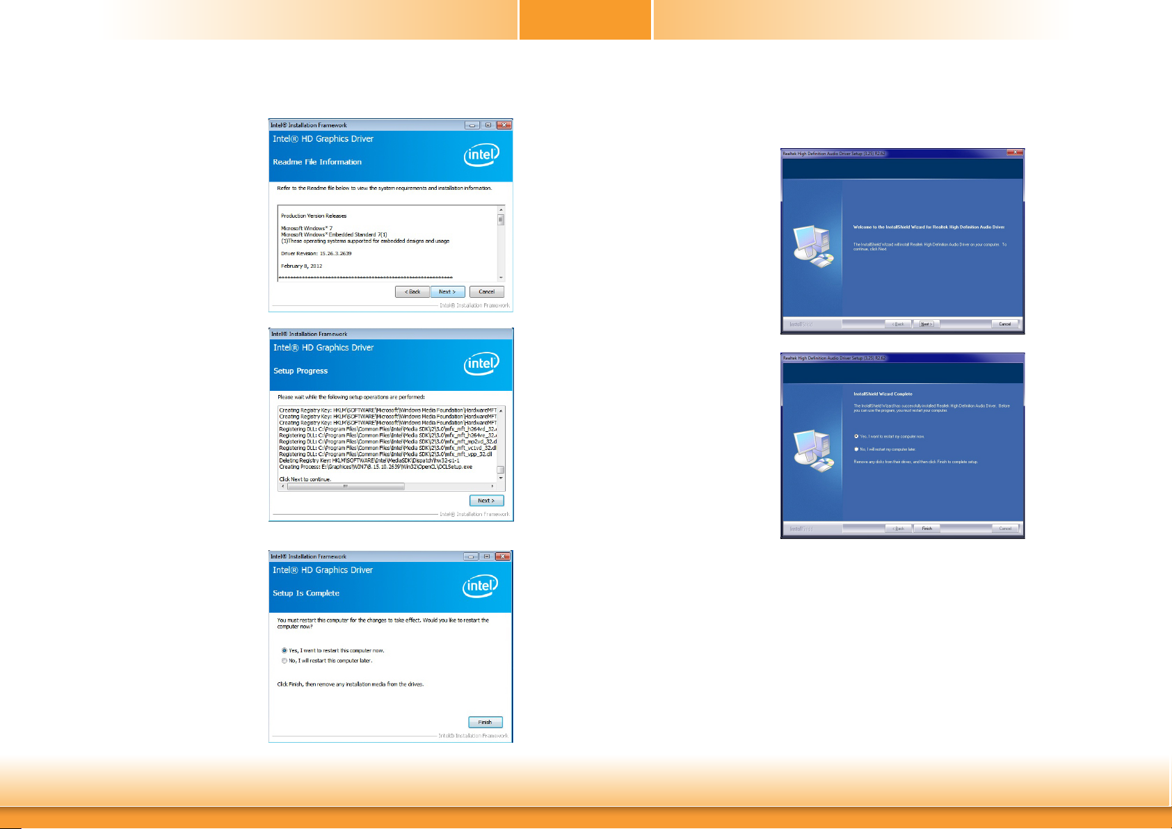
3. Go through the readme
document for system requirements and installation
tips then click Next.
4. Setup is now installing the
driver. Click Next to continue.
Chapter 4
► Audio Drivers
To install the driver, click “Audio Drivers” on the main menu.
1. Setup is ready to install the
driver. Click Next.
2. Click “Yes, I want to restart
my computer now” then
click Finish.
Restarting the system will
allow the new software
installation to take effect.
5. Click “Yes, I want to restart
this computer now” then
click Finish.
Restarting the system will
allow the new software
installation to take effect.
Chapter 4 Supported Software
53
www.d.com
Page 54
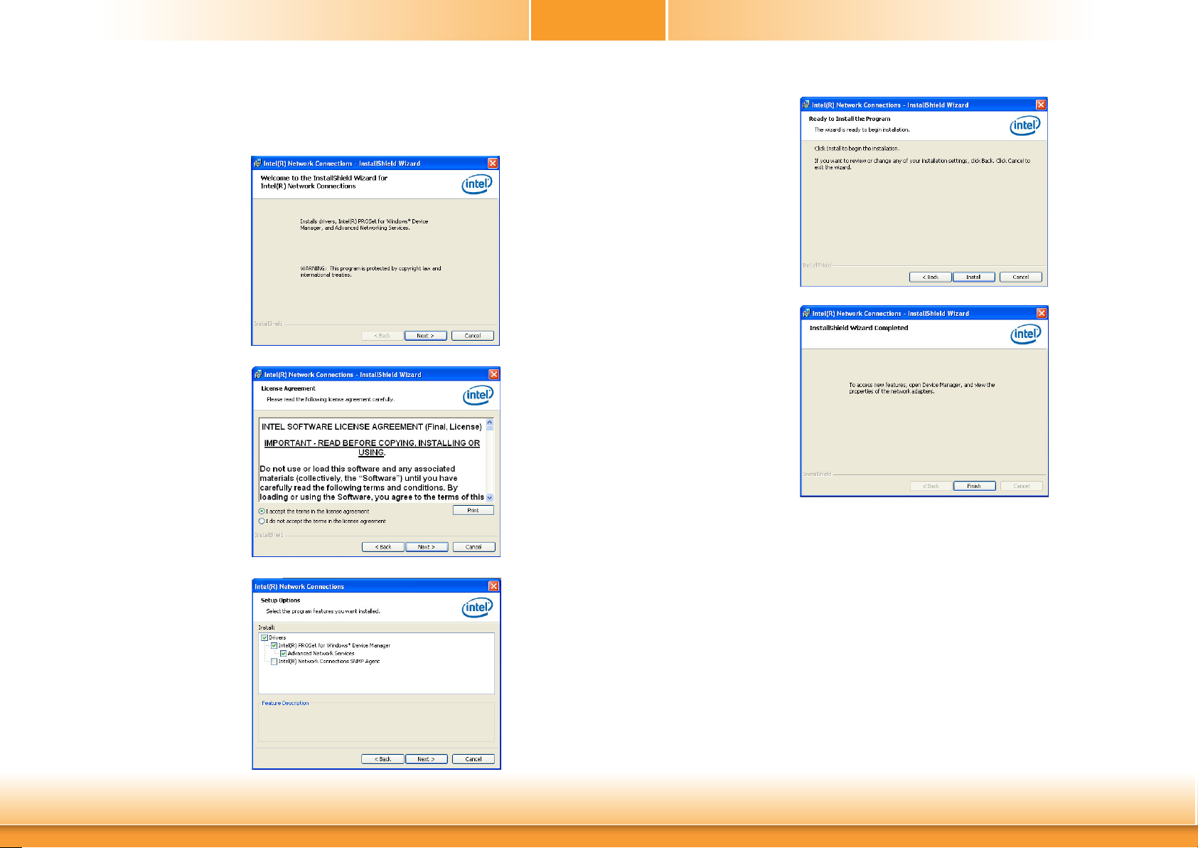
Chapter 4
► Intel LAN Drivers
To install the driver, click “Intel LAN Drivers” on the main menu.
1. Setup is ready to install the
driver. Click Next.
2. Click “I accept the terms
in the license agreement”
then click “Next”.
4. Click Install to begin the
installation.
5. After completing installation, click Finish.
3. Select the program featuers
you want installed then
click Next.
Chapter 4 Supported Software
54
www.d.com
Page 55
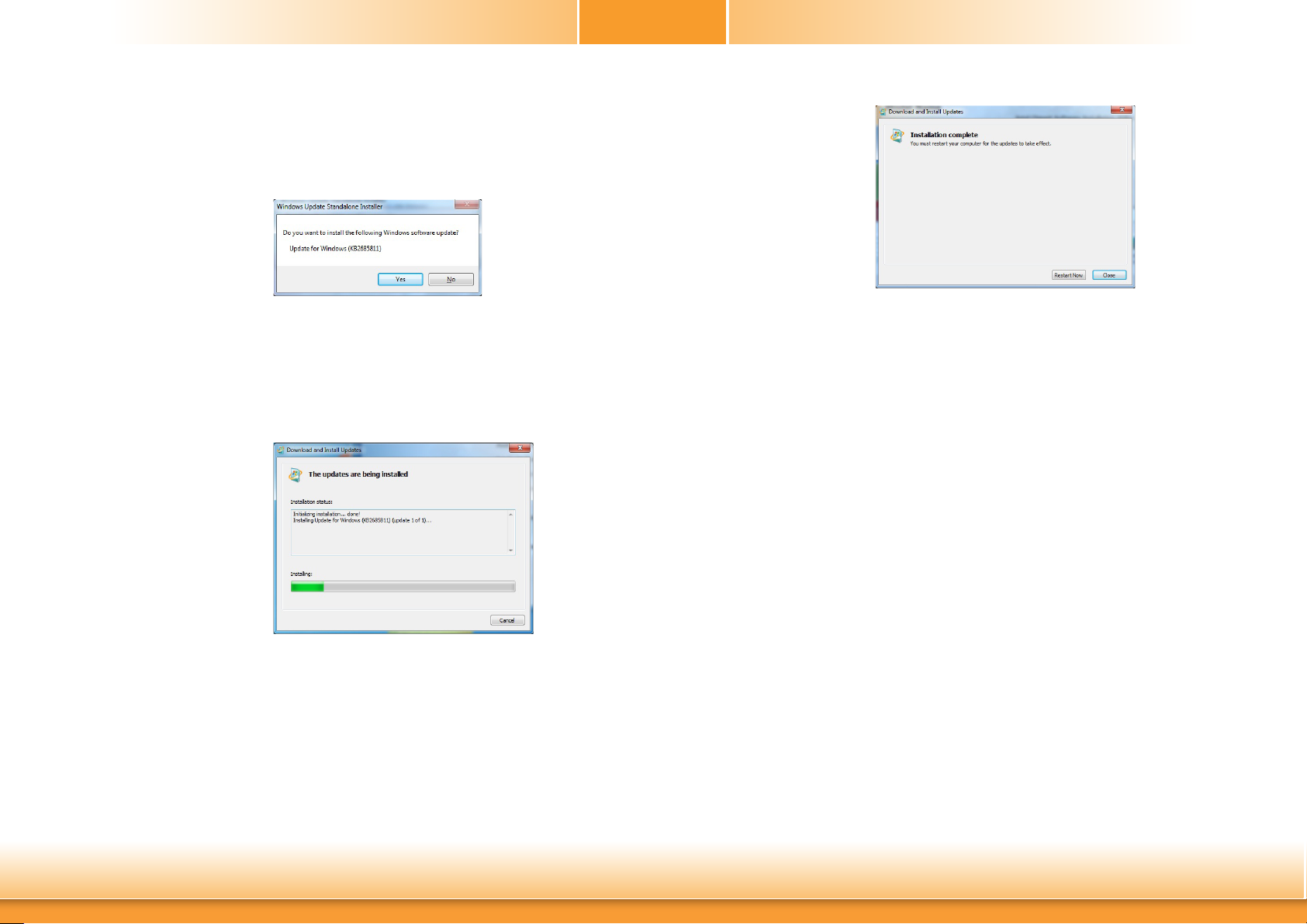
Chapter 4
► Kernel Mode Driver Framework (For Windows 7 only)
To install the driver, click “Kernel Mode Driver Framework” on the main menu.
1. Click “Yes“ to install the
update.
2. The update is installed
now.
3. Click “Restart Now“ to
restart your computer when
the installation is complete.
Chapter 4 Supported Software
55
www.d.com
Page 56

Chapter 4
► Intel Management Engine Drivers
To install the driver, click “Intel Management Engine Drivers” on the main menu.
1. Setup is ready to install the
driver. Click Next.
2. Read the license agreement
then click Next.
3. Setup is currently installing
the driver. After installation
has completed, click Next.
4. Please wait while the product is being installed.
Chapter 4 Supported Software
5. After completing installation, click Finish.
56
www.d.com
Page 57
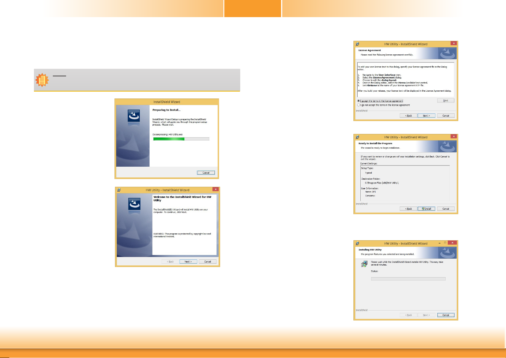
Chapter 4
► HW Utility
HW Utility provides information about the board, Watchdog,and DIO. To access the utility, click
“HW Utility” on the main menu.
Note:
If you are using Windows 7 or later versions, you need to access the operating system as an administrator to be able to install the utility.
1. Setup is ready to install the
driver.
2. Click “Next” to continue.
3. Read the license agreement
then click “I accept the terms
in the license agreement”.
Click “Next”.
4. The wizard is ready to begin
installation. Click “Install”.
Chapter 4 Supported Software
5. Please wait while the program
features are being installed.
57
www.d.com
Page 58

Chapter 4
6. After completing installation, click “Finish”.
The HW Utility icon will appear on the desktop. Double-click the icon to open the utility.
Information
Chapter 4 Supported Software
HW Health
58
www.d.com
Page 59
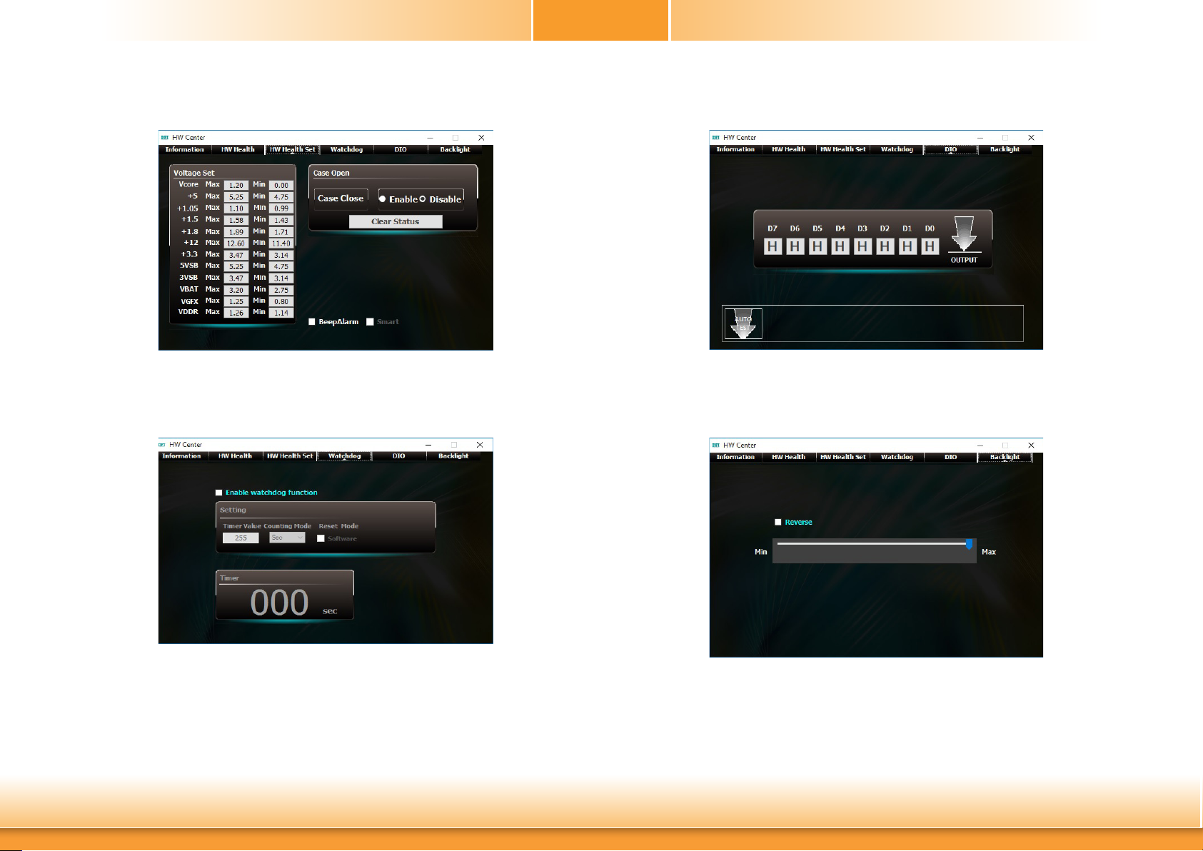
Chapter 4
HW Health Set
WatchDog
DIO
Backlight
Chapter 4 Supported Software
59
www.d.com
Page 60
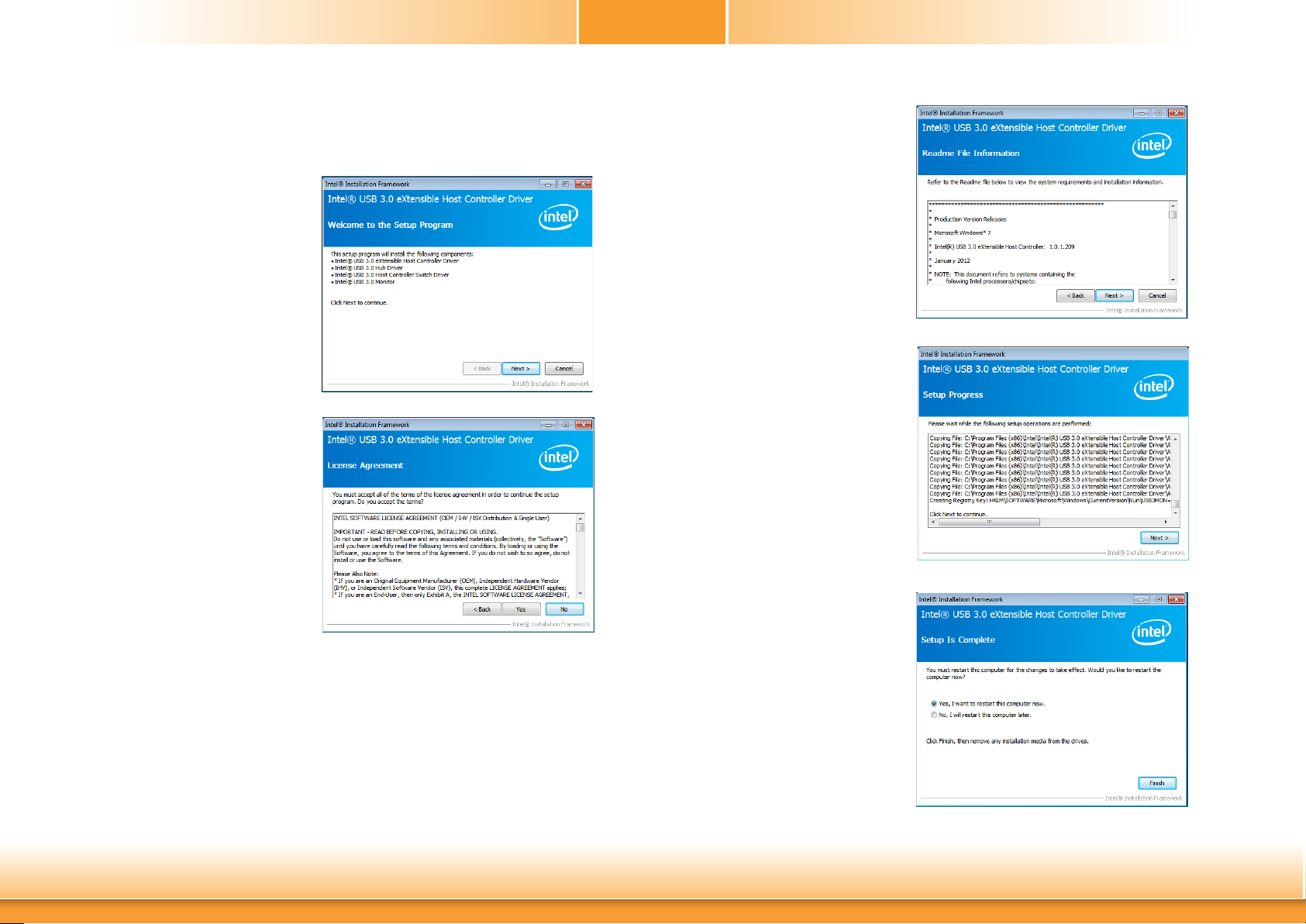
Chapter 4
► Intel USB 3.0 Drivers (For Windows 7 and Windows 8.1)
To install the driver, click “Intel USB 3.0 Driver” on the main menu.
1. Setup is ready to install the driver.
Click Next.
2. Read the license agreement then
click Yes.
3. Go through the readme document for more installation tips
then click Next.
4. Setup is currently installing the
driver. After installation has completed, click Next.
Chapter 4 Supported Software
5. After completing installation, click
Finish.
60
www.d.com
Page 61
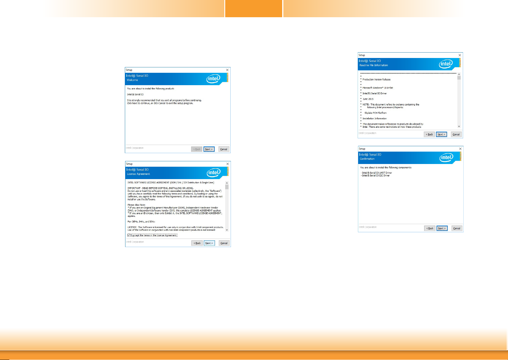
► IO Driver (For Windows 8.1 and Windows 10)
To install the driver, click “Intel Serial IO Driver” on the main menu
1. Setup is ready to install the driver.
Click Next.
2. Read the license agreement carefully.
Click “I accept the terms in the Li-
cense Agreement” then click Next.
Chapter 4
3. Read the file information then click
Next.
4. Setup is ready to install the driver.
Click Next.
Chapter 4 Supported Software
61
www.d.com
Page 62
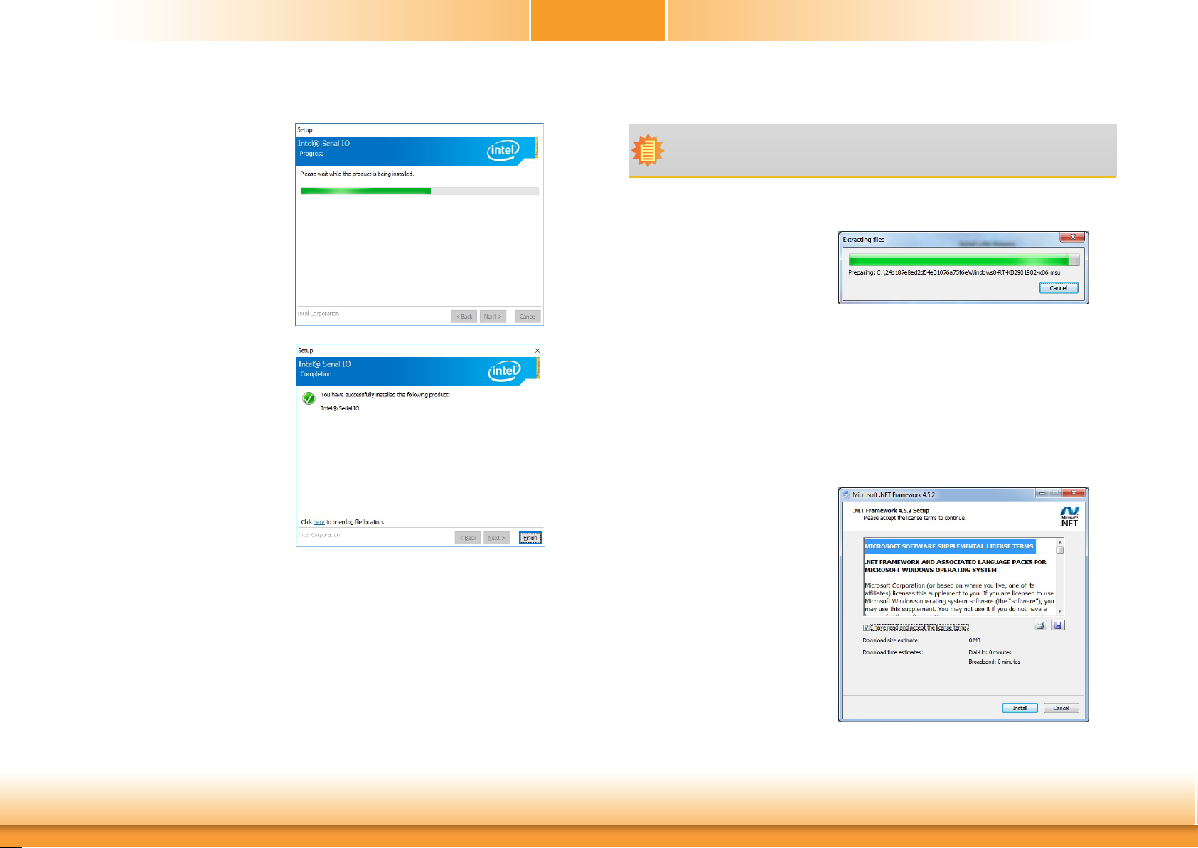
5. Setup is now installing the
driver.
6. Click Finish.
Chapter 4
► Microsoft Framework 4.5.2 (For Windows 7)
Note:
Before installing Microsoft Framework 4.5.2, make sure you have updated your
Windows 7 operating system to Service Pack 3.
To install the driver, click “Microsoft Framework 4.5.2” on the main menu.
1. Setup is now extracting files.
Chapter 4 Supported Software
2. Read the license agreement carefully.
Click “I have read and accept
the terms of the License Agree
ment” then click Install.
62
www.d.com
Page 63
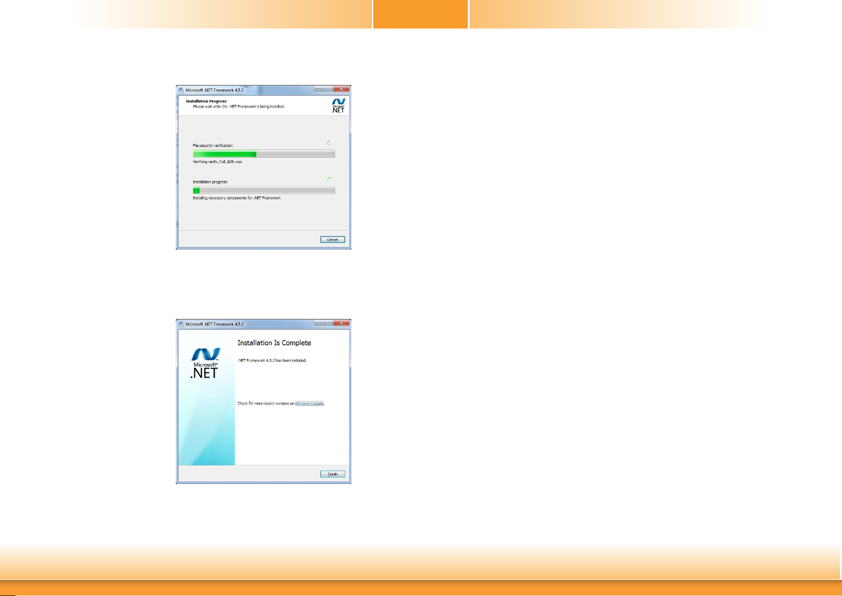
3. Setup is now installing the
driver.
Chapter 4
► Intel Rapid Storage Technology
The Intel Rapid Storage Technology is a utility that allows you to monitor the current status
of the SATA drives. It enables enhanced performance and power management for the storage
subsystem.
To install the driver, click “Intel Rapid Storage Technology” on the main menu. Please refer to
Chapter 5 for more information.
4. Click Finish.
Chapter 4 Supported Software
63
www.d.com
Page 64
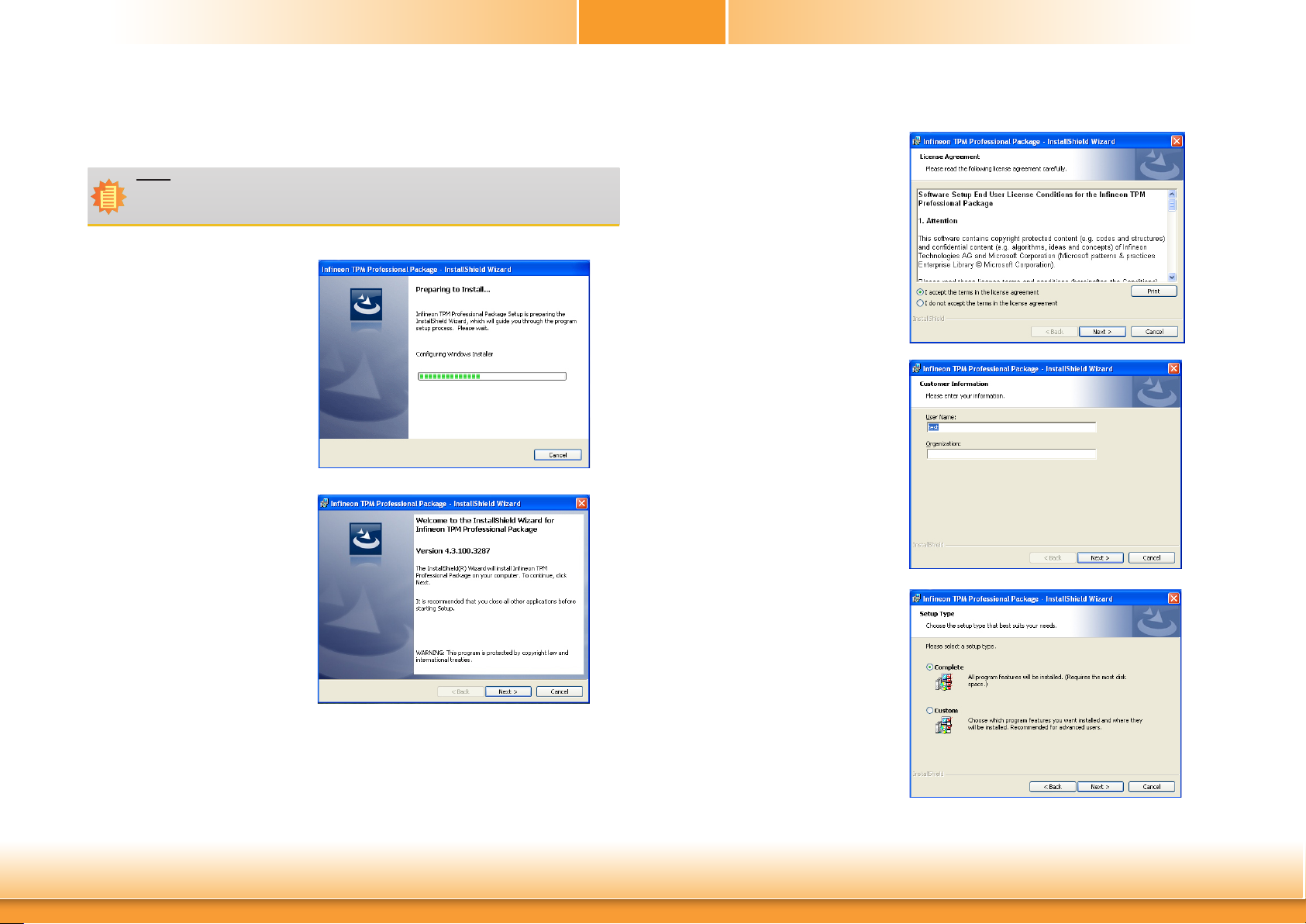
► Infineon TPM 1.2 Driver and Tool (optional)
To install the driver, click “Infineon TPM driver and tool (option)” on the main menu.
Note:
1. This driver only supports TPM 1.2.
2. TPM 2.0 is only supported on Windows 8.1 / Windows 10; for Windows 7, please
turn off TPM 2.0 in the BIOS if the TPM configuration exists.
1. The setup program is preparing
to install the driver.
Chapter 4
3. Click “I accept the terms in the
license agreement” and then
click “Next”.
4. Enter the necessary information
and then click Next.
2. The setup program is now ready
to install the utility. Click Next.
Chapter 4 Supported Software
5. Select a setup type and then click
Next.
64
www.d.com
Page 65
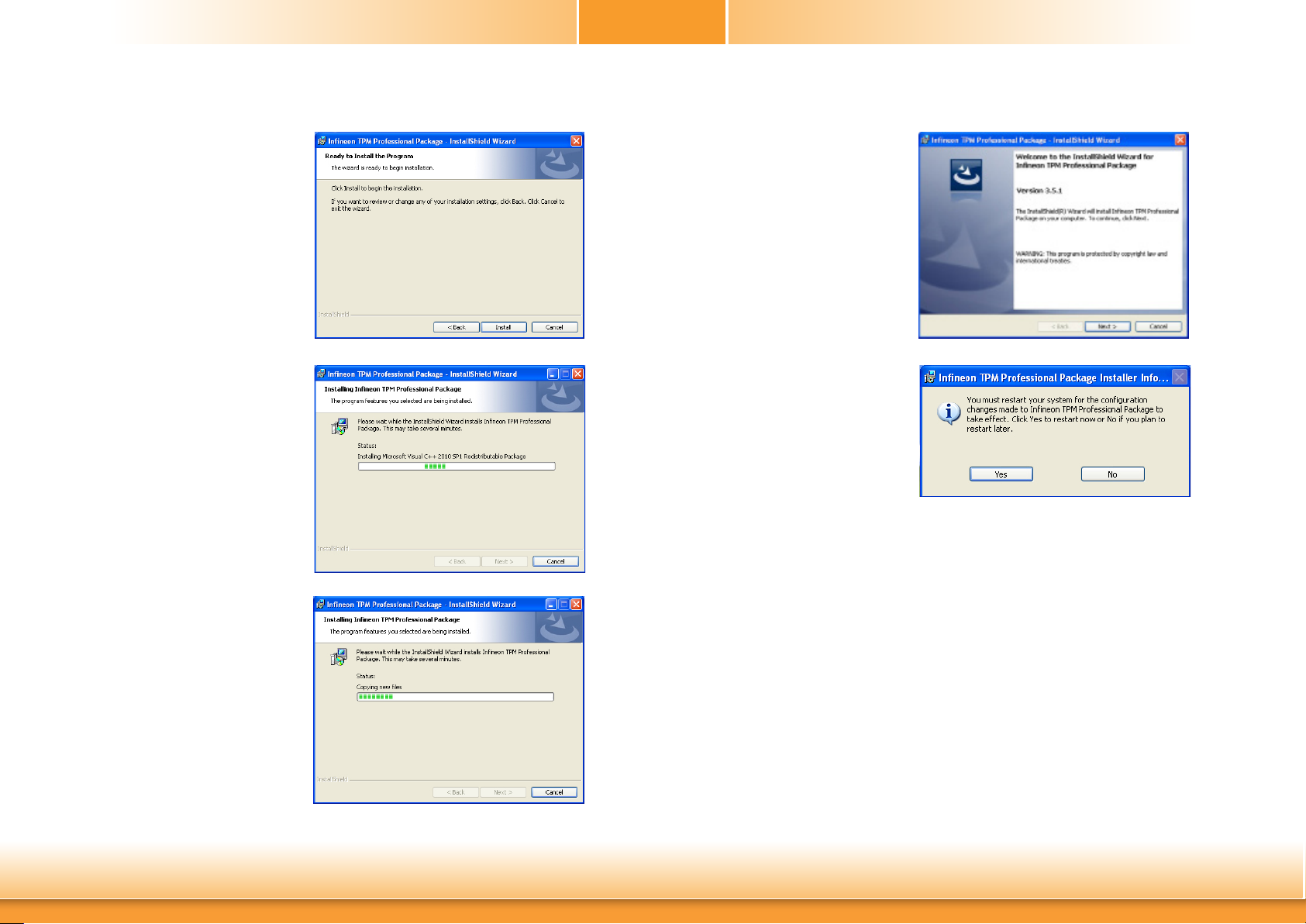
Chapter 4
6. Click Install. 9. Click Finish.
7. TPM requires installing the Microsoft Visual C++ package prior to
installing the utility. Click Install.
8. The setup program is currently
installing the Microsoft Visual
C++ package.
10. Click “Yes“ to restart your system.
Chapter 4 Supported Software
65
www.d.com
Page 66
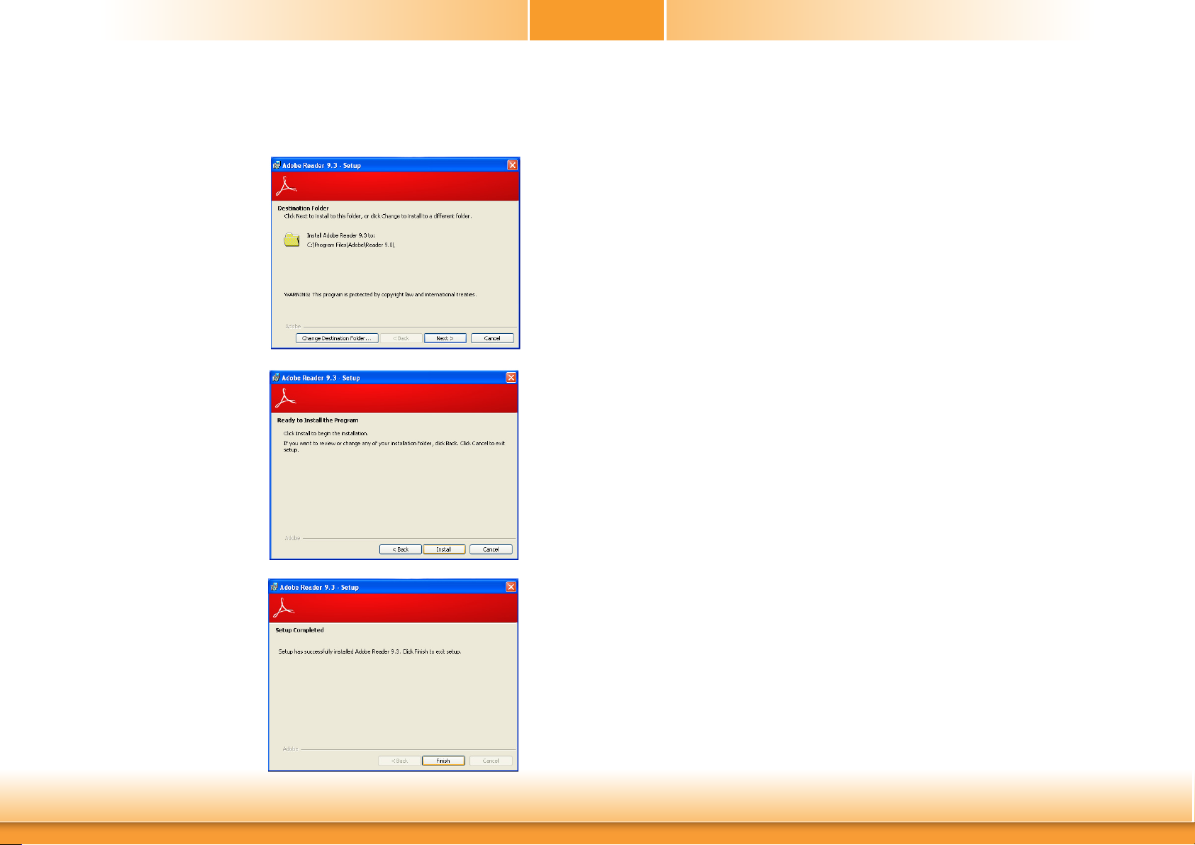
► Adobe Acrobat Reader 9.3
To install the reader, click “Adobe Acrobat Reader 9.3” on the main menu.
1. Click Next to install or click
Change Destination Folder
to select another folder.
2. Click Install to begin installa-
tion.
Chapter 4
3. Click Finish to exit installation.
Chapter 4 Supported Software
66
www.d.com
Page 67
Chapter 5 - RAID
The system board allows configuring RAID on Serial ATA drives. It supports RAID 0, RAID 1,
RAID 5 and RAID 10.
Chapter 5
Settings
To enable the RAID function, the following settings are required.
RAID Levels
RAID 0 (Striped Disk Array without Fault Tolerance)
RAID 0 uses two new identical hard disk drives to read and write data in parallel, interleaved
stacks. Data is divided into stripes and each stripe is written alternately between two disk
drives. This improves the I/O performance of the drives at different channel; however it is not
fault tolerant. A failed disk will result in data loss in the disk array.
RAID 1 (Mirroring Disk Array with Fault Tolerance)
RAID 1 copies and maintains an identical image of the data from one drive to the other drive.
If a drive fails to function, the disk array management software directs all applications to the
other drive since it contains a complete copy of the drive’s data. This enhances data protection
and increases fault tolerance to the entire system. Use two new drives or an existing drive and
a new drive but the size of the new drive must be the same or larger than the existing drive.
RAID 5
RAID 5 stripes data and parity information across hard drives. It is fault tolerant and provides
better hard drive performance and more storage capacity.
RAID 10 (Mirroring and Striping)
RAID 10 is a combination of data striping and data mirroring providing the benefits of both
RAID 0 and RAID 1. Use four new drives or an existing drive and three new drives for this
configuration.
RAID Level Min. Drives Protection Description
RAID 0 2 None Data striping without redundancy
1. Connect the Serial ATA drives.
2. Enable RAID in the Insyde BIOS.
3. Create a RAID volume.
3-1. Create a RAID volume if the boot type is UEFI.
4. Install the Intel Rapid Storage Technology Utility.
Step 1: Connect the Serial ATA Drives
Refer to chapter 2 for details on connecting the Serial ATA drives.
Important:
1. Make sure you have installed the Serial ATA drives and connected the data cables
otherwise you won’t be able to enter the RAID BIOS utility.
2. Treat the cables with extreme caution especially while creating RAID. A damaged
cable will ruin the entire installation process and operating system. The system will
not boot and you will lost all data in the hard drives. Please give special attention
to this warning because there is no way of recovering back the data.
Step 2: Enable RAID in the Insyde BIOS
1. Power-on the system then press <Del> to enter the main menu of the Insyde BIOS.
2. Go to “Advanced” menu and select the “SATA Configuration” menu.
3. Change the “SATA Mode Selection” to “RAID” mode.
4. Save the changes in the “Exit” menu.
5. Reboot the system.
RAID 1 2 Single Drive Failure Disk mirroring
RAID 5 3 Single Drive Failure
RAID 10 4
1 Disk Per Mirrored
Stripe (not same mirror)
Block-level data striping with
distributed parity
Combination of RAID 0 (data striping)
and RAID 1 (mirroring)
Chapter 5 RAID
67
www.d.com
Page 68

Chapter 5
Step 3: Create a RAID Volume
1. When the Intel® RST option ROM status screen displays during POST, press <Ctrl> and
<I> simultaneously to enter the option ROM user interface.
2. Select 1: Create RAID Volume and press <Enter>.
3. Create a volume name and press <Enter>.
4. Use the up or down arrow keys to select the RAID level and press <Enter>.
5. Use the up or down arrow keys to select the strip size and press <Enter>.
6. Select the capacity and press <Enter>. You must select less than one hundred percent of
the available volume space to leave space for the second volume.
7. Press <Enter> to create the volume.
8. At the prompt, press <Y> to confirm volume creation.
9. Select 4: Exit and press <Enter>.
10. Press <Y> to confirm exit.
Step 3-1: Create a RAID Volume if the boot type is UEFI
If the boot type is set to UEFI, RAID volume creation will be dierent. Please use the following
steps to create RAID volumes. To set the boot type, enter the Insyde BIOS and go to “Boot” >
“Boot Type”.
1. Go to the “Advanced” menu of the Insyde BIOS and select “Device Manager”.
Main Advanced
ACPI Conguration
CPU Conguration
Video Conguration
Audio Conguration
SATA Conguration
USB Conguration
PCI Express Conguration
ME Conguration
Active Management Technology Support
MEBX Conguration
Debug Conguration
Device Manager
SIO NUVOTON6106D
Console Redirection
F1 Help ↑/↓ Select Item F5/F6 Change Values F9 Setup Defaults
Esc Exit ←/→ Select Item Enter Select SubMenu F10 Save and Exit
Security Boot Exit
InsydeH2O Setup Utility
Device Manager Setting
2. The screen displays all available drives. Select “Create RAID volume” to create a RAID
volume.
3. Use the up or down arrow keys to select the RAID level and press <Enter>.
Rev. 5.0
Chapter 5 RAID
4. Use the up or down arrow keys to scroll through the list of hard drives and press <Enter>
to select the drive.
5. Press <Enter>.
6. Use the up or down arrow keys to select the strip size and press <Enter>.
7. Enter the volume size and press <Enter>.
8. At the prompt, press <Y> to confirm volume creation.
68
www.d.com
Page 69
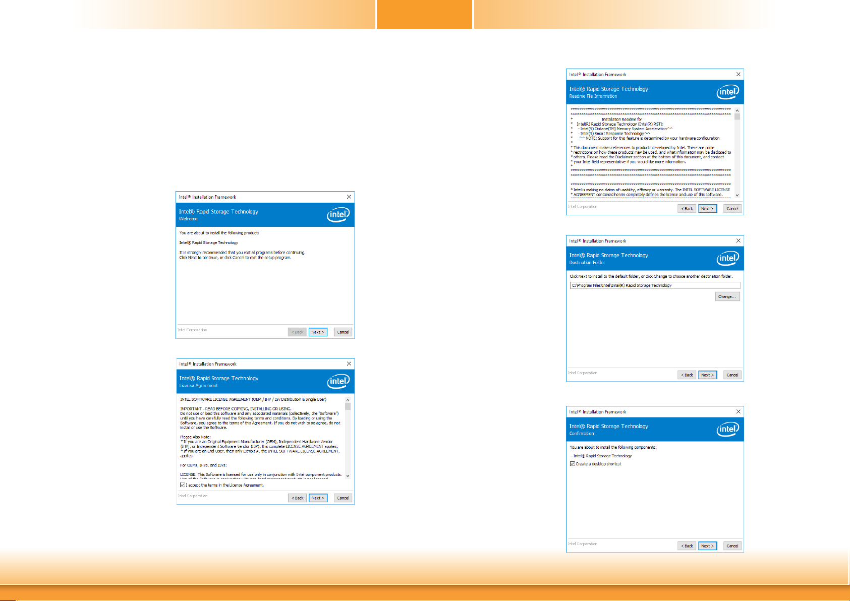
Chapter 5
Step 4: Install the Intel Rapid Storage Technology Utility
The Intel Rapid Storage Technology Utility can be installed from within Windows. It allows
RAID volume management (create, delete, migrate) from within the operating system. It will
also display useful SATA device and RAID volume information. The user interface, tray icon
service and monitor service allow you to monitor the current status of the RAID volume and/
or SATA drives. It enables enhanced performance and power management for the storage
subsystem.
1. Download “SD106 IRST Driver” zip file at our website.
2. Setup is ready to install
the utility. Click “Next”.
3. Read the license agreement and click “I accept
the terms in the License
Agreement”. Then, click
“Next”.
4. Go through the readme
document to view system
requirements and installation information then click
“Next”.
5. Click “Next” to install to
the default folder or click
“Change to choose another
destination folder”.
6. Confirm the installation and
click “Next”.
Chapter 5 RAID
69
www.d.com
Page 70
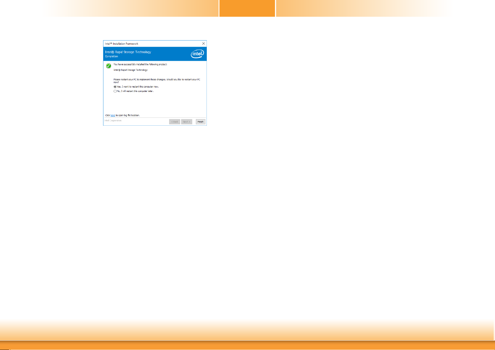
7. Click “Yes, I want to restart
this computer now” to
complete the installation
and then click “Finish”.
Chapter 5
Chapter 5 RAID
70
www.d.com
Page 71

Chapter 6 - Intel AMT Settings
Chapter 6
► Enabling Intel® AMT in the Insyde BIOS
► Overview
Intel Active Management Technology (Intel® AMT) combines hardware and software solution to
provide maximum system defense and protection to networked systems.
The hardware and software information are stored in non-volatile memory. With its built-in
manageability and latest security applications, Intel® AMT provides the following functions.
Discover
Allows remote access and management of networked systems even while PCs are powered off;
significantly reducing desk-side visits.
Repair
Remotely repair systems after OS failures. Alerting and event logging help detect problems
quickly to reduce downtime.
Protect
Intel AMT’s System Defense capability remotely updates all systems with the latest security
software. It protects the network from threats at the source by proactively blocking incoming
threats, reactively containing infected clients before they impact the network, and proactively
alerting when critical software agents are removed.
1. Power-on the system then press <Del> to enter the main menu of the Insyde BIOS.
2. In the Advanced menu, select Active Management Technology Support.
Main Advanced
ACPI Conguration
CPU Conguration
Video Conguration
Audio Conguration
SATA Conguration
USB Conguration
PCI Express Conguration
ME Conguration
Active Management Technology Support
MEBX Conguration
Debug Conguration
Device Manager
SIO NUVOTON6106D
Console Redirection
F1 Help ↑/↓ Select Item F5/F6 Change Values F9 Setup Defaults
Esc Exit ←/→ Select Item Enter Select SubMenu F10 Save and Exit
Security Boot Exit
InsydeH2O Setup Utility
AMT Conguration
Rev. 5.0
3. Select Enabled in the Intel AMT Support field.
Advanced
Active Management Technology Support
Intel AMT Support <Enabled>
Un-Congure ME <Disabled>
InsydeH2O Setup Utility Rev. 5.0
When disabled AMT
BIOS Features are no
longer supported and user
is no longer able to access
MEBx Setup.
Note :
This option does not disable Manageability Features in FW.
Rev. 5.0
Chapter 6 Intel AMT Settings
F1 Help ↑/↓ Select Item F5/F6 Change Values F9 Setup Defaults
Esc Exit ←/→ Select Item Enter Select SubMenu F10 Save and Exit
71
www.d.com
Page 72
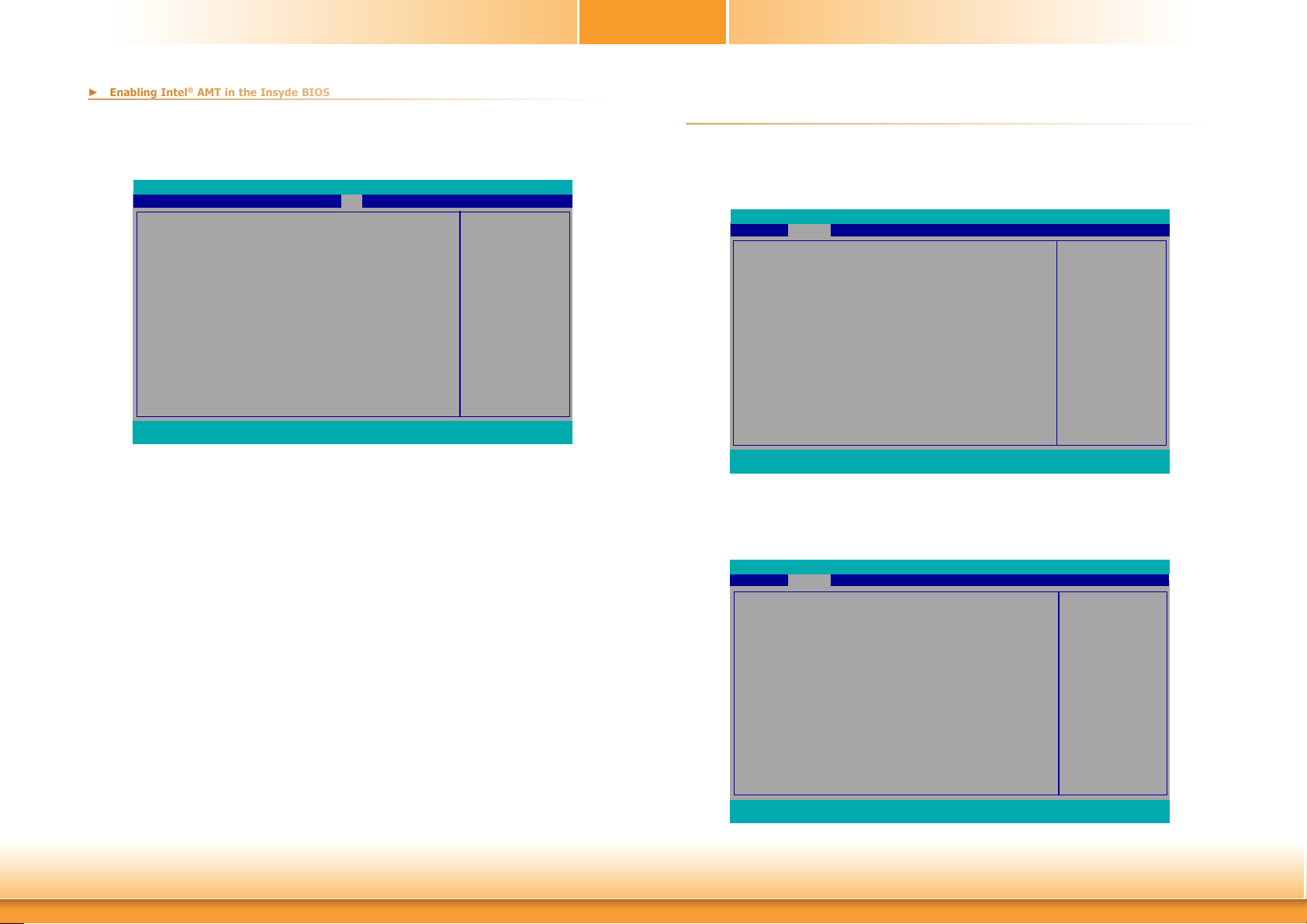
4. In the Exit menu, select Exit Saving Changes then select Yes and press Enter.
► Enabling Intel® AMT in the Insyde BIOS
Main Advanced
Exit Saving Changes
Load Optimal Defaults
Discard Changes
F1 Help ↑/↓ Select Item F5/F6 Change Values F9 Setup Defaults
Esc Exit ←/→ Select Item Enter Select SubMenu F10 Save and Exit
Security Boot
InsydeH2O Setup Utility
Exit
Exit system setup and save
your changes.
Rev. 5.0
Chapter 6
1. After the system reboots, press <Del> to enter the main menu of the Insyde BIOS.
2. In the Advanced menu, select MEBX Configuration.
► Entering Management Engine BIOS Extension (MEBx)
Main Advanced
ACPI Conguration
CPU Conguration
Video Conguration
Audio Conguration
SATA Conguration
USB Conguration
PCI Express Conguration
ME Conguration
Active Management Technology Support
MEBX Conguration
Debug Conguration
Device Manager
SIO NUVOTON6106D
Console Redirection
F1 Help ↑/↓ Select Item F5/F6 Change Values F9 Setup Defaults
Esc Exit ←/→ Select Item Enter Select SubMenu F10 Save and Exit
Security Boot Exit
InsydeH2O Setup Utility
MEBX Configuration Setting
Rev. 5.0
Chapter 6 Intel AMT Settings
3. Select MEBX Configuration and press Enter.
Advanced
MEBX Conguration
MEBX Conguration
F1 Help ↑/↓ Select Item F5/F6 Change Values F9 Setup Defaults
Esc Exit ←/→ Select Item Enter Select SubMenu F10 Save and Exit
72
InsydeH2O Setup Utility Rev. 5.0
MEBX Configuration Setting
Rev. 5.0
www.d.com
Page 73
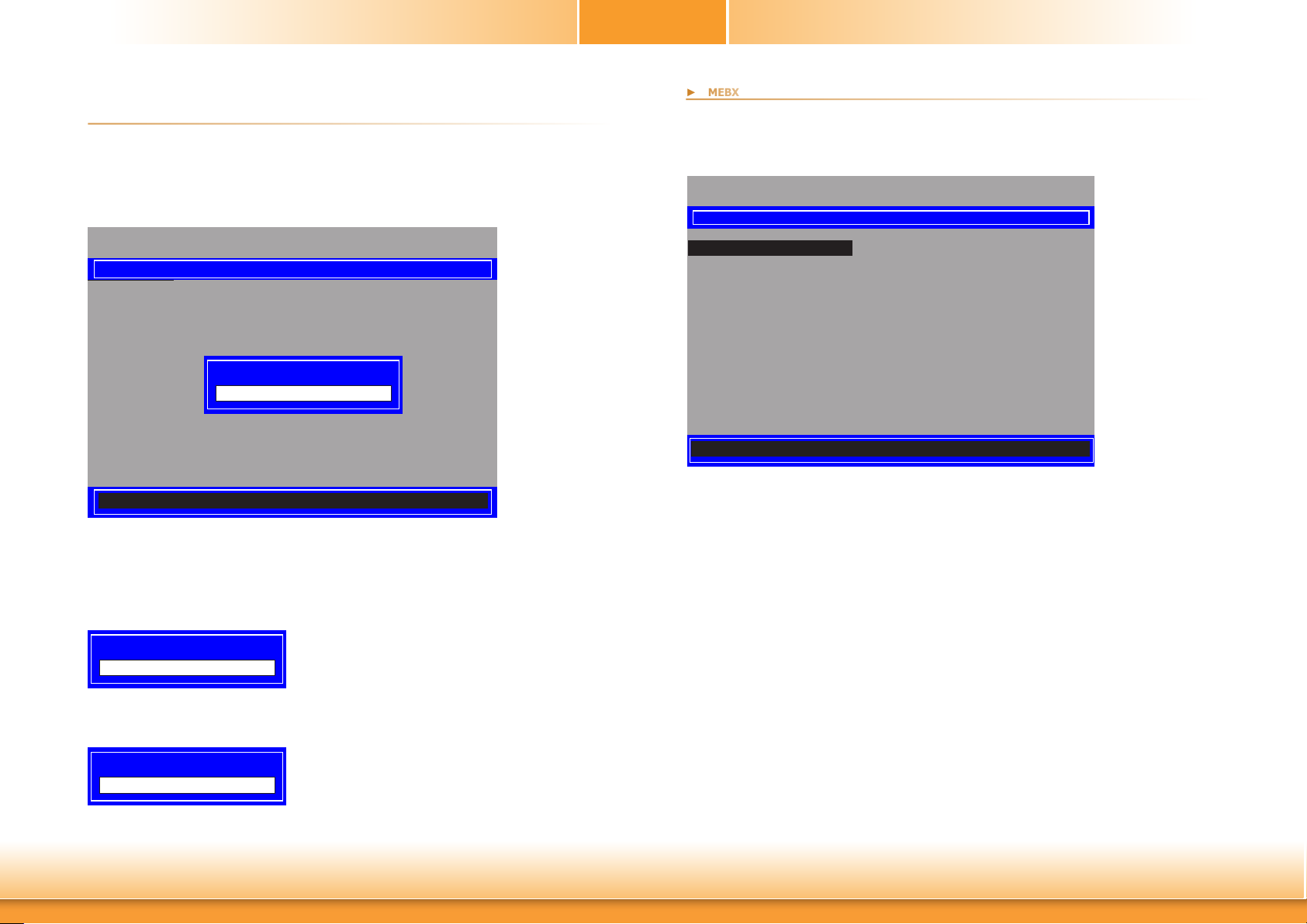
Chapter 6
► MEBX
► MEBX
Main Menu
Select MEBx Login under Main Menu and press Enter. You will be prompted for a password.
The default password is “admin”. Enter the default password in the prompt and then press
Enter.
Intel(R) Management Engine BIOS Extension v11.0.0.0010/Intel(R) ME v11.8.55.3510
Copyright(C) 2003-16 Intel Corporation. All Rights Reserved
MAIN MENU
MEBx Login
> Intel(R) ME General Settings
> Intel(R) AMT Conguration
MEBx Exit
Intel(R) ME Password
Intel(R) ME Password
[↑↓] =Move Highlight [Enter] =Select Entry [Esc] =Exit
Enter a new password in the prompt and then press Enter. The password must include:
• 8-32 characters
• Strong 7-bit ASCII characters excluding : , and ” characters
• At least one digit character (0, 1, ...9)
• At least one 7-bit ASCII non alpha-numeric character, above 0x20, (e.g. !, $, ;)
• Both lower case and upper case characters
Intel(R) ME General Settings
Select Intel(R) ME General Settings under Main Menu and then press Enter.
Intel(R) Management Engine BIOS Extension v11.0.0.0010/Intel(R) ME v11.8.55.3510
Copyright(C) 2003-16 Intel Corporation. All Rights Reserved
MAIN MENU
> Intel(R) ME General Settings
> Intel(R) AMT Conguration
MEBx Exit
[↑↓] =Move Highlight [Enter] =Select Entry [Esc] =Exit
Intel(R) ME New Password
You will be asked to verify the new password. Enter the same new password in the prompt
and then press Enter.
Verify password
Chapter 6 Intel AMT Settings
73
www.d.com
Page 74
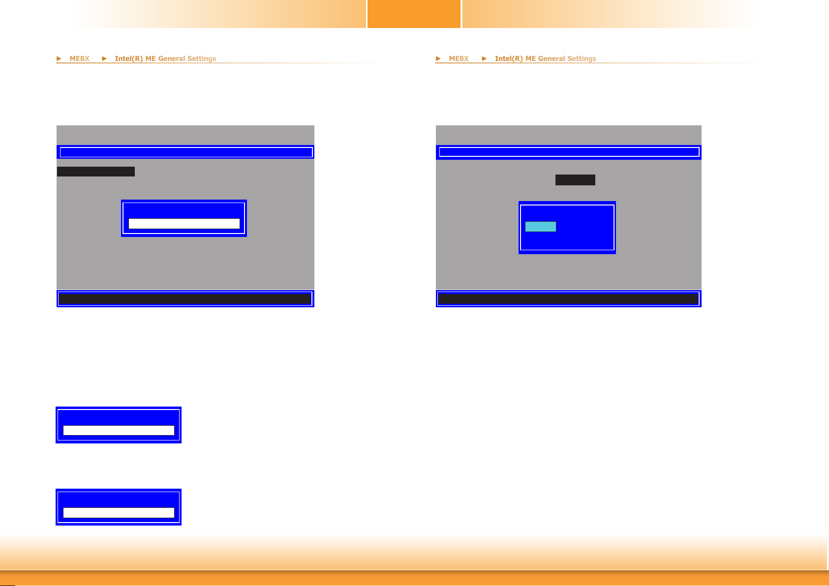
Chapter 6
► MEBX
► MEBX
► Intel(R) ME General Settings
► Intel(R) ME General Settings
Change ME Password
If you want to change ME password, select Change ME Password then press Enter. Enter
the current password in the space provided under Intel(R) ME Password then press Enter.
Intel(R) Management Engine BIOS Extension v11.0.0.0010/Intel(R) ME v11.8.55.3510
Copyright(C) 2003-16 Intel Corporation. All Rights Reserved
INTEL(R) ME PLATFORM CONFIGURATION
Change ME Password
Local FW Update <Enabled>
Intel(R) ME Password
Intel(R) ME New Password
[↑↓] =Move Highlight [Enter] =Select Entry [Esc] =Exit
Enter a new password in the space provided under Intel(R) ME New Password then press Enter. The password must include:
• 8-32 characters
• Strong 7-bit ASCII characters excluding : , and ” characters
• At least one digit character (0, 1, ...9)
• At least one 7-bit ASCII non alpha-numeric character, above 0x20, (e.g. !, $, ;)
• Both lower case and upper case characters
Local FW Update
Select Local FW Update then press Enter. Select Enabled or Disabled or Password Protected then press Enter.
Intel(R) Management Engine BIOS Extension v11.0.0.0010/Intel(R) ME v11.8.55.3510
Copyright(C) 2003-16 Intel Corporation. All Rights Reserved
INTEL(R) ME PLATFORM CONFIGURATION
Change ME Password
Local FW Update <Enabled>
Disabled
Enabled
Password Protected
[↑↓] =Move Highlight <Enter> =Complete Entry [Esc] =Discard Changes
Intel(R) ME New Password
You will be asked to verify the new password. Enter the same new password in the space provided under Verify Password then press Enter.
Verify password
Chapter 6 Intel AMT Settings
74
www.d.com
Page 75
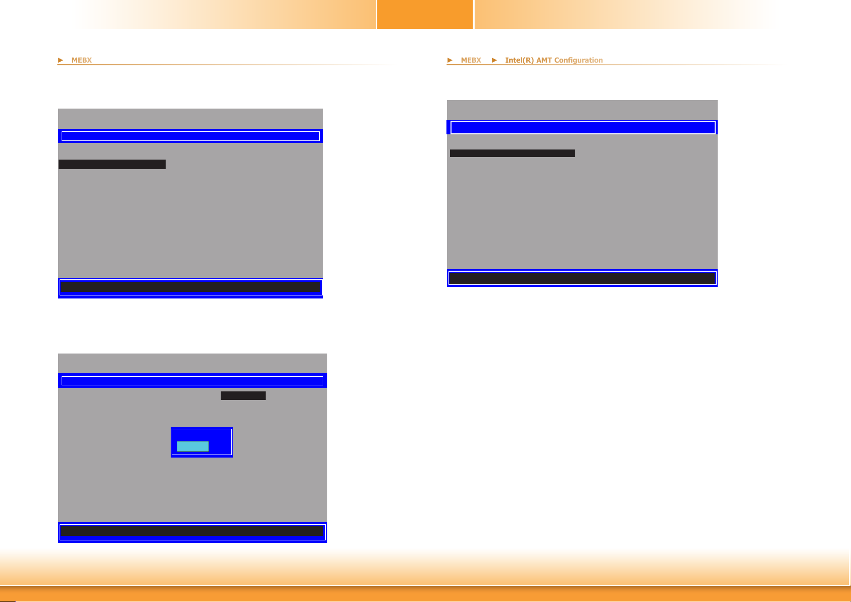
Chapter 6
► MEBX
► MEBX
► Intel(R) AMT Configuration
Intel(R) AMT Configuration
Select Intel(R) AMT Configuration under Main Menu and then press Enter.
Intel(R) Management Engine BIOS Extension v11.0.0.0010/Intel(R) ME v11.8.55.3510
> Intel(R) ME General Settings
> Intel(R) AMT Conguration
[↑↓] =Move Highlight [Enter] =Select Entry [Esc] =Exit
Manageability Feature Selection
Select Enabled or Disabled then press Enter. When disabled, all the following fields will be
hidden. After disabling the field, system restart is required.
Intel(R) Management Engine BIOS Extension v11.0.0.0010/Intel(R) ME v11.8.55.3510
Copyright(C) 2003-16 Intel Corporation. All Rights Reserved
MAIN MENU
MEBx Exit
Copyright(C) 2003-16 Intel Corporation. All Rights Reserved
INTEL(R) AMT CONFIGURATION
Manageability Feature Selection <Enabled>
> SOL/Storage Redirection/KVM
> User Consent
Password Policy <Anytime>
> Network Setup
Activate Network Access
Uncongure Network Access <Full Unprovision>
> Remote Setup And Conguration
> Power Control
Disabled
Enabled
> SOL/Storage Redirection/KVM
Intel(R) Management Engine BIOS Extension v11.0.0.0010/Intel(R) ME v11.8.55.3510
Copyright(C) 2003-16 Intel Corporation. All Rights Reserved
INTEL(R) AMT CONFIGURATION
Manageability Feature Selection <Enabled>
> SOL/Storage Redirection/KVM
> User Consent
Password Policy <Anytime>
> Network Setup
Activate Netwok Access
Uncongure Network Access <Full Unprovision>
> Remote Setup And Conguration
> Power Control
[↑↓] =Move Highlight [Enter] =Select Entry [Esc] =Exit
Press Enter to enter the submenu.
[↑↓] =Move Highlight <Enter> =Complete Entry [Esc] =Discard Changes
Chapter 6 Intel AMT Settings
75
www.d.com
Page 76

Chapter 6
► MEBX
► Intel(R) AMT Configuration
► MEBX
► Intel(R) AMT Configuration
> SOL/Storage Redirection/KVM
> User Consent
Intel(R) Management Engine BIOS Extension v11.0.0.0010/Intel(R) ME v11.8.55.3510
Copyright(C) 2003-16 Intel Corporation. All Rights Reserved
SOL/Storage Redirection/KVM
Username and Password <Enabled>
SOL <Enabled>
Storage Redirection <Enabled>
KVM Feature Selection <Enabled>
[↑↓] =Move Highlight <Enter> =Complete Entry [Esc] =Discard Changes
Move the cursor to select a field and press Enter to display options.
Username and Password
Select Enabled or Disabled then press Enter.
SOL
Select Enabled or Disabled then press Enter.
Intel(R) Management Engine BIOS Extension v11.0.0.0010/Intel(R) ME v11.8.55.3510
Copyright(C) 2003-16 Intel Corporation. All Rights Reserved
INTEL(R) AMT CONFIGURATION
Manageability Feature Selection <Enabled>
> SOL/Storatge Redirection/KVM
> User Consent
Password Policy <Anytime>
> Network Setup
Activate Netwok Access
Uncongure Network Access <Full Unprovision>
> Remote Setup And Conguration
> Power Control
[↑↓] =Move Highlight [Enter] =Select Entry [Esc] =Exit
Press Enter to enter the submenu.
Storage Redirection
Select Enabled or Disabled then press Enter.
KVM Feature Selection
Select Enabled or Disabled then press Enter.
Disabled
Enabled
Chapter 6 Intel AMT Settings
76
www.d.com
Page 77

Chapter 6
► MEBX
► Intel(R) AMT Configuration
► MEBX
► Intel(R) AMT Configuration
> User Consent
Password Policy
Intel(R) Management Engine BIOS Extension v11.0.0.0010/Intel(R) ME v11.8.55.3510
Copyright(C) 2003-16 Intel Corporation. All Rights Reserved
USER CONSENT
User Opt-in <KVM>
Opt-in Congurable from Remote IT <Enabled>
[↑↓] =Move Highlight <Enter> =Complete Entry [Esc] =Discard Changes
Move the cursor to select a field and press Enter to display options.
User Opt-in
Select NONE or KVM or ALL then press Enter.
NONE
KVM
ALL
Intel(R) Management Engine BIOS Extension v11.0.0.0010/Intel(R) ME v11.8.55.3510
Manageability Feature Selection <Enabled>
> SOL/Storage Redirection/KVM
> User Consent
Password Policy <Anytime>
> Network Setup
Activate Network Access
Uncongure Network Access <Full Unprovision>
> Remote Setup And Conguration
> Power Control
[↑↓] =Move Highlight <Enter> =Complete Entry [Esc] =Discard Changes
Under the Intel(R) AMT Configuration menu, select Password Policy then press Enter.
You may choose to use a password only during setup and configuration or to use a password
anytime the system is being accessed.
Copyright(C) 2003-16 Intel Corporation. All Rights Reserved
INTEL(R) AMT CONFIGURATION
Default Password Only
During Setup And Conguration
Anytime
Opt-in Configurable from Remote IT
Select Enabled or Disabled then press Enter.
Disabled
Enabled
Chapter 6 Intel AMT Settings
77
www.d.com
Page 78
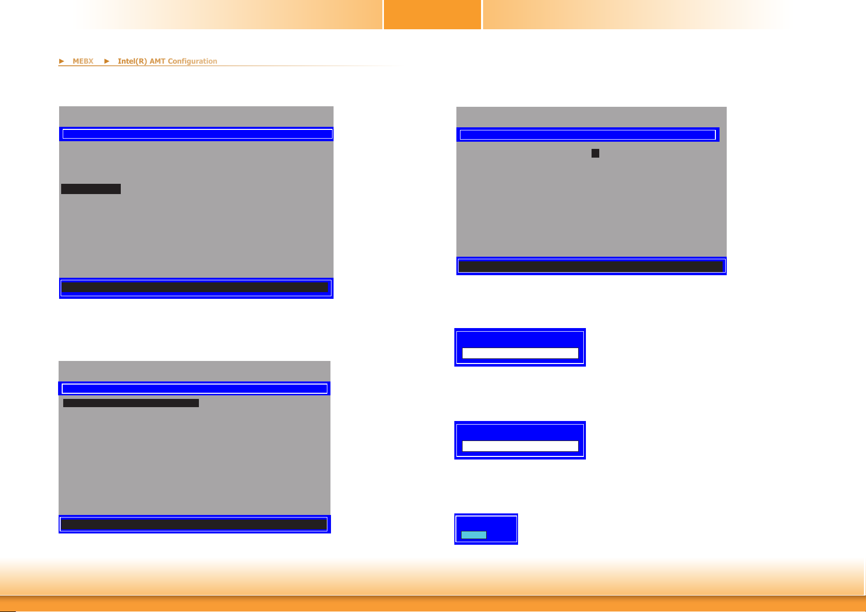
> Network Setup
► MEBX
► Intel(R) AMT Configuration
Chapter 6
Under the Intel(R) AMT Configuration menu, select Network Setup and then press Enter.
Intel(R) Management Engine BIOS Extension v11.0.0.0010/Intel(R) ME v11.8.55.3510
Copyright(C) 2003-16 Intel Corporation. All Rights Reserved
INTEL(R) AMT CONFIGURATION
Manageability Feature Selection <Enabled>
> SOL/Storage Redirection/KVM
> User Consent
Password Policy <Anytime>
> Network Setup
Activate Network Access
Uncongure Network Access <Full Unprovision>
> Remote Setup And Conguration
> Power Control
[↑↓] =Move Highlight [Enter] =Select Entry [Esc] =Exit
> Intel(R) ME Network Name Settings
Under the Intel(R) ME Network Setup menu, select Intel(R) ME Network Name Settings and then press Enter.
Intel(R) Management Engine BIOS Extension v11.0.0.0010/Intel(R) ME v11.8.55.3510
Copyright(C) 2003-16 Intel Corporation. All Rights Reserved
INTEL(R) ME NETWORK SETUP
> Intel(R) ME Network Name Settings
> TCP/IP Settings
Move the cursor to select a field and press Enter to display options.
Intel(R) Management Engine BIOS Extension v11.0.0.0010/Intel(R) ME v11.8.55.3510
Host Name
Domain Name
Sha re d/ De dic ate d FQ DN
Dynamic DNS Update
<Enter> =Complete Entry [Esc] =Discard Changes
Host Name
Enter the computer’s host name and then press Enter.
Domain Name
Enter the computer’s domain name and then press Enter.
Copyright(C) 2003-16 Intel Corporation. All Rights Reserved
INTEL(R) ME NETWORK NAME SETTINGS
_
_
<Shared>
<Disabled>
Computer Host Name
[↑↓] =Move Highlight [Enter] =Select Entry [Esc] =Exit
Chapter 6 Intel AMT Settings
Computer Domain Name
Shared/Dedicated FQDN
Select Shared or Dedicated and then press Enter.
Dedicated
Shared
78
www.d.com
Page 79
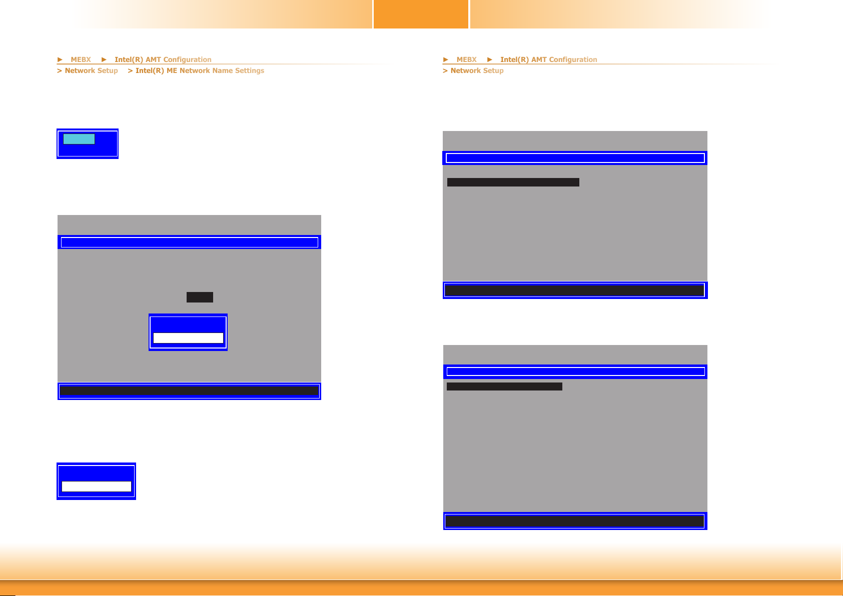
Chapter 6
► MEBX
► Intel(R) AMT Configuration
> Network Setup
> Network Setup
> Intel(R) ME Network Name Settings
► MEBX
► Intel(R) AMT Configuration
Dynamic DNS Update
Select Enabled or Disabled then press Enter. When Dynamic DNS Update is Enabled, the following fields will show up.
Disabled
Enabled
Periodic Update Interval
Enter a value and then press Enter.
Intel(R) Management Engine BIOS Extension v11.0.0.0010/Intel(R) ME v11.8.55.3510
Copyright(C) 2003-16 Intel Corporation. All Rights Reserved
INTEL(R) ME NETWORK NAME SETTINGS
Host Name
Domain Name
Shared/Dedicated FQDN
Dynamic DNS Update
Periodic Update Interval
TTL
_
_
<Shared>
<Enabled>
1440
900
Value=0 or >=20
1440
<Enter> =Complete Entry [Esc] =Discard Changes
> TCP/IP Settings
Under the Intel(R) ME Network Setup menu, select TCP/IP Settings and then press Enter.
Intel(R) Management Engine BIOS Extension v11.0.0.0010/Intel(R) ME v11.8.55.3510
Copyright(C) 2003-16 Intel Corporation. All Rights Reserved
INTEL(R) ME NETWORK SETUP
> Intel(R) ME Network Name Settings
> TCP/IP Settings
[↑↓] =Move Highlight [Enter] =Select Entry [Esc] =Exit
> Wired LAN IPV4 Configuration
Under TCP/IP Settings, select Wired LAN IPV4 Configuration and then press Enter.
Intel(R) Management Engine BIOS Extension v11.0.0.0010/Intel(R) ME v11.8.55.3510
Copyright(C) 2003-16 Intel Corporation. All Rights Reserved
TCP/IP SETTINGS
> Wired LAN IPV4 Conguration
TTL
Enter a value for the Time-to-live (TTL) field and then press Enter.
Value in Seconds
900
Chapter 6 Intel AMT Settings
[↑↓] =Move Highlight [Enter] =Select Entry [Esc] =Exit
79
www.d.com
Page 80
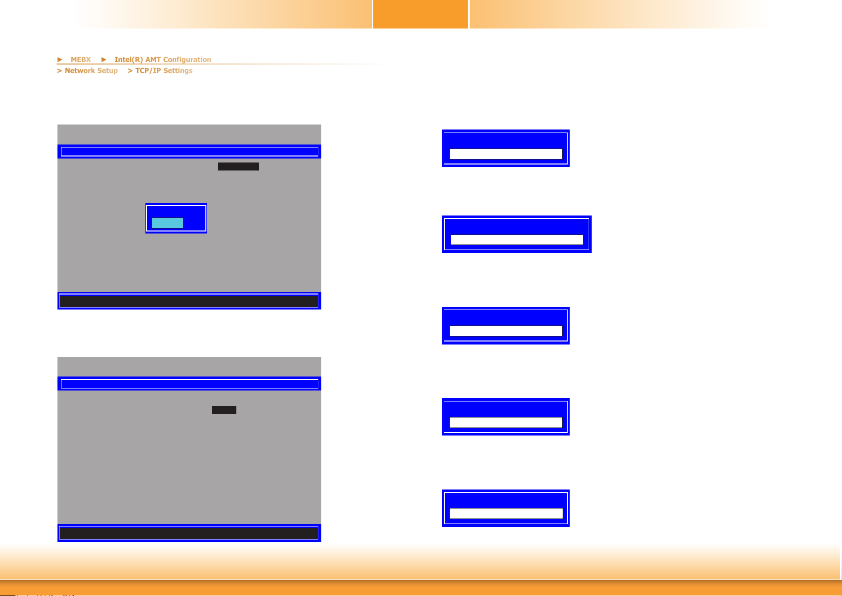
Chapter 6
► MEBX
► Intel(R) AMT Configuration
> Network Setup
> TCP/IP Settings
DHCP Mode
Select Enabled or Disabled then press Enter. Please make sure there is a DHCP server in the
network when this field is enabled.
Intel(R) Management Engine BIOS Extension v11.0.0.0010/Intel(R) ME v11.8.55.3510
Copyright(C) 2003-16 Intel Corporation. All Rights Reserved
WIRED LAN IPV4 CONFIGURATION
DHCP Mode <Enabled>
Disabled
Enabled
[↑↓] =Move Highlight <Enter> =Complete Entry [Esc] =Discard Changes
When DHCP is Disabled, please manually input a static route by configuring the fields as
shown below.
Intel(R) Management Engine BIOS Extension v11.0.0.0010/Intel(R) ME v11.8.55.3510
Copyright(C) 2003-16 Intel Corporation. All Rights Reserved
WIRED LAN IPV4 CONFIGURATION
DHCP Mode <Disabled>
IPV4 Address 0.0.0.0
Subnet Mask Address 0.0.0.0
Default Gateway Address 0.0.0.0
Preferred DNS Address 0.0.0.0
Alternate DNS Address 0.0.0.0
IPv4 Address
Assign a valid and available IP address to the system. Insert a value from 0.0.0.0 to
255.255.255.255 in IPv4 format.
IP address (e.g. 123.123.123.100)
0.0.0.0
Subnet Mask Address
Insert a value from 0.0.0.0 to 255.255.255.255 in IPv4 format.
Subnet mask (e.g. 255.255.255.0)
0.0.0.0
Default Gateway Address
Insert a value from 0.0.0.0 to 255.255.255.255 in IPv4 format.
Default Gateway address
0.0.0.0
Preferred DNS Address
Insert a value from 0.0.0.0 to 255.255.255.255 in IPv4 format.
Preferred DNS address
0.0.0.0
Alternate DNS Address
Insert a value from 0.0.0.0 to 255.255.255.255 in IPv4 format.
<Enter> =Complete Entry [Esc] =Discard Changes
Chapter 6 Intel AMT Settings
Alternate DNS address
0.0.0.0
80
www.d.com
Page 81
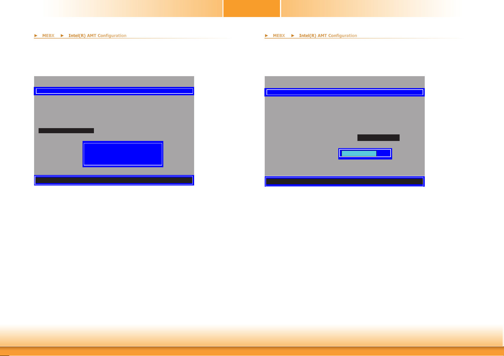
Chapter 6
► MEBX
► Intel(R) AMT Configuration
► MEBX
► Intel(R) AMT Configuration
Activate Network Access
Under the Intel(R) AMT Configuration menu, select Activate Network Access and press
Enter, and then press Y to activate the ME network connection with the settings configured
previously, or press N to abort.
Intel(R) Management Engine BIOS Extension v11.0.0.0010/Intel(R) ME v11.8.55.3510
Manageability Feature Selection <Enabled>
> SOL/Storage Redirection/KVM
> User Consent
Password Policy <Anytime>
> Network Setup
Activate Network Access
Uncongure Network Access <Full Unprovision>
> Remote Setup And Conguration
> Power Control
[↑↓] =Move Highlight [Enter] =Select Entry [Esc] =Exit
Copyright(C) 2003-16 Intel Corporation. All Rights Reserved
INTEL(R) AMT CONFIGURATION
Activates the current network settings
and opens the ME network interface
Continue: (Y/N)
Unconfigure Network Access
Under the Intel(R) AMT Configuration menu, select Undconfigure Network Access and
press Enter, and then press Enter to fully deactivate the ME network connection and reset configuration to factory default. Press Y to confirm or N to abort.
Intel(R) Management Engine BIOS Extension v11.0.0.0010/Intel(R) ME v11.8.55.3510
Manageability Feature Selection <Enabled>
> SOL/Storage Redirection/KVM
> User Consent
Password Policy <Anytime>
> Network Setup
Activate Network Access
Uncongure Network Access <Full Unprovision>
> Remote Setup And Conguration
> Power Control
[↑↓] =Move Highlight <Enter> =Complete Entry [Esc] =Discard Changes
Copyright(C) 2003-16 Intel Corporation. All Rights Reserved
INTEL(R) AMT CONFIGURATION
Full Unprovision
Chapter 6 Intel AMT Settings
81
www.d.com
Page 82
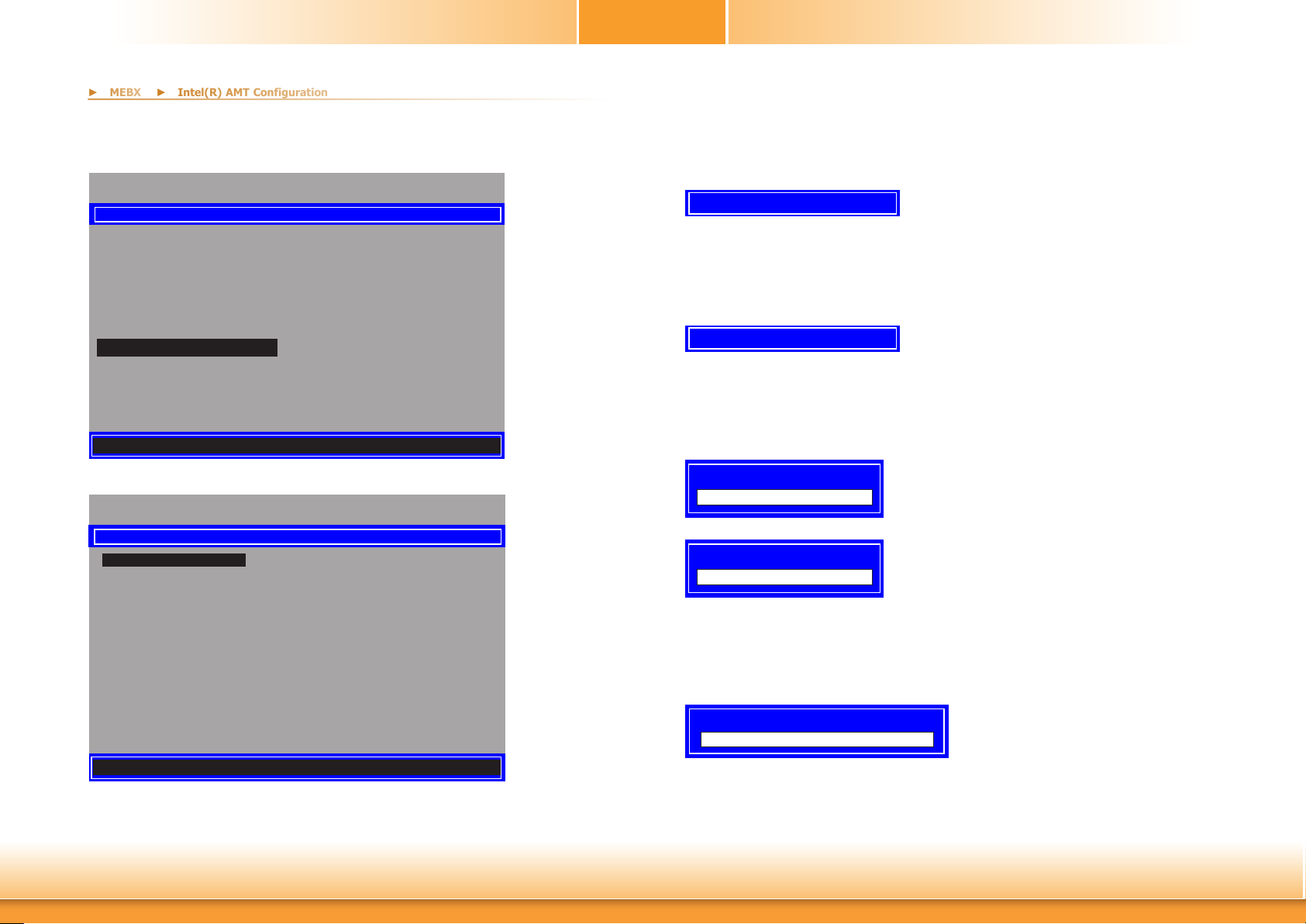
Chapter 6
► MEBX
► Intel(R) AMT Configuration
> Remote Setup And Configuration
Under the Intel(R) AMT Configuration menu, select Remote Setup And Configuration
then press Enter.
Intel(R) Management Engine BIOS Extension v11.0.0.0010/Intel(R) ME v11.8.55.3510
Copyright(C) 2003-16 Intel Corporation. All Rights Reserved
INTEL(R) AMT CONFIGURATION
Manageability Feature Selection <Enabled>
> SOL/Storage Redirection/KVM
> User Consent
Password Policy <Anytime>
> Network Setup
Activate Network Access
Uncongure Network Access <Full Unprovision>
> Remote Setup And Conguration
> Power Control
Current Provisioning Mode
The current mode — Public Key Infrastructure (PKI) — is displayed.
Provisioning Mode: PKI
Provisioning Record
Press Enter to view the record.
Provision Record is not present
[↑↓] =Move Highlight [Enter] =Select Entry [Esc] =Exit
Intel(R) Management Engine BIOS Extension v11.0.0.0010/Intel(R) ME v11.8.55.3510
Copyright(C) 2003-16 Intel Corporation. All Rights Reserved
INTEL (R) REMOTE SETUP AND CONFIGURATION
Current Provisioning Mode
Provisioning Record
Provisioning Server IPV4/IPV6 _
Provisioning Server FQDN _
> RCFG
> TLS PKI
[↑↓] =Move Highlight [Enter] =Select Entry [Esc] =Exit
Provisioning Server IPV4/IPV6
Enter the address of the server then press Enter, and then insert the TCP/UDP port number.
Provisioning server address
Port number (0-65535)
Provisioning Server FQDN
Enter the Fully Qualified Domain Name (FQDN) of the server and then press Enter.
Enter FQDN of provisioning server
[ESC] = Exit
Chapter 6 Intel AMT Settings
82
www.d.com
Page 83

Chapter 6
► MEBX
► MEBX
► Intel(R) AMT Configuration
► Intel(R) AMT Configuration
> Remote Setup And Configuration
> Remote Setup And Configuration
> RCFG
Press Enter, select Start Configuration, and then press Enter to activate Remote Configuration (RCFG). Press Y to confirm or N to abort.
Intel(R) Management Engine BIOS Extension v11.0.0.0010/Intel(R) ME v11.8.55.3510
Copyright(C) 2003-16 Intel Corporation. All Rights Reserved
INTEL(R) REMOTE CONFIGURATION
Start Conguration
This will activate Remote Conguration.
Continue: (Y/N)
[↑↓] =Move Highlight [Enter] =Select Entry [Esc] =Exit
> TLS PKI
The system adopts PKI for encryption and authentication, and the TLS protocol for communication security to ensure remote configuration safety.
Intel(R) Management Engine BIOS Extension v11.0.0.0010/Intel(R) ME v11.8.55.3510
Copyright(C) 2003-16 Intel Corporation. All Rights Reserved
INTEL(R) REMOTE CONFIGURATION
Remote Conguration ** <Enabled>
PKI DNS Sux _
> Manage Hashes
[↑↓] =Move Highlight <Enter> =Complete Entry [Esc] =Discard Changes
Remote Configuration **
Select Enabled or Disabled then press Enter.
Chapter 6 Intel AMT Settings
Disabled
Enabled
PKI DNS Suffix
Specify the DNS Suffix of the PKI server, and then press Enter.
Enter PKI DNS Sux
83
www.d.com
Page 84
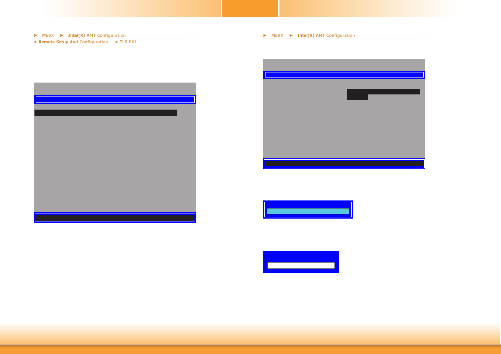
Chapter 6
► MEBX
► MEBX
► Intel(R) AMT Configuration
► Intel(R) AMT Configuration
> Remote Setup And Configuration
> TLS PKI
> Manage Hashes
Select the hash name then press Insert to enter custom hash certificate name, press Delete to
delete hash, press Enter to view hash information, press + to activate or deactivate hash, and
press Esc to exit.
> Power Control
Under the Intel(R) AMT Configuration menu, select Power Control then press Enter.
Intel(R) Management Engine BIOS Extension v11.0.0.0010/Intel(R) ME v11.8.55.3510
Copyright(C) 2003-16 Intel Corporation. All Rights Reserved
INTEL(R) AMT POWER CONTROL
Intel(R) Management Engine BIOS Extension v11.0.0.0010/Intel(R) ME v11.8.55.3510
Copyright(C) 2003-16 Intel Corporation. All Rights Reserved
INTEL(R) REMOTE CONFIGURATION
Hash Name Active Default Algorithm
VeriSign Class 3
VeriSign Class 3
Go Daddy Class 2
Comodo AAA CA
Stareld Class 2
VeriSign Class 3
VeriSign Class 3
VeriSign Class 3
GTE CyberTrust G1
Baltimore Cyber Tr
Cyber Trust Global
Verizon Global Ro
Entrust. net CA (2
Entrust Root CA
VeriSign Universa
Go Daddy Root CA
Entrust Root CA -
Starteld Root CA
[Ins] =Add New Hash [Delete] =Delete Hash [+] =Activate Hash
[↑↓] =Move Highlight [Enter] =View Hash [Esc] =Exit
Active: [*]
Active: [*]
Active: [*]
Active: [*]
Active: [*]
Active: [*]
Active: [*]
Active: [*]
Active: [*]
Active: [*]
Active: [*]
Active: [*]
Active: [*]
Active: [*]
Active: [*]
Active: [*]
Active: [*]
Active: [*]
Default: [*]
Default: [*]
Default: [*]
Default: [*]
Default: [*]
Default: [*]
Default: [*]
Default: [*]
Default: [*]
Default: [*]
Default: [*]
Default: [*]
Default: [*]
Default: [*]
Default: [*]
Default: [*]
Default: [*]
Default: [*]
SHA256
SHA256
SHA256
SHA256
SHA256
SHA256
SHA256
SHA256
SHA256
SHA256
SHA256
SHA256
SHA256
SHA256
SHA256
SHA256
SHA256
SHA256
These congurations are eective only after AMT provisioning has started
Intel(R) AMT ON in Host Sleep States
Idle Timeout 65535
<Desktop: ON in S0, ME Wake in
S3, S4-5>
[↑↓] =Move Highlight <Enter> =Complete Entry [Esc] =Discard Changes
Intel(R) AMT ON in Host Sleep States
Select an option and then press Enter.
↓
Desktop: ON in S0
Desktop: ON in S0, ME Wake in S3, S4-5
Idle Timeout
Enter a timeout value and press Enter.
Timeout Value (1-65535)
65535
Chapter 6 Intel AMT Settings
84
www.d.com
Page 85
Chapter 6
► MEBX
MEBx Exit
Under the Main Menu, select MEBx Exit and then press Enter. Press Y to confirm or N to
abort.
Intel(R) Management Engine BIOS Extension v11.0.0.0010/Intel(R) ME v11.8.55.3510
> Intel(R) ME General Settings
> Intel(R) AMT Conguration
MEBx Exit
Exit
[↑↓] =Move Highlight [Enter] =Select Entry [Esc] =Exit
Copyright(C) 2003-16 Intel Corporation. All Rights Reserved
MAIN MENU
Are you sure you want to exit?(Y/N):
Chapter 6 Intel AMT Settings
85
www.d.com
 Loading...