

Page 1

NP101-D16C
System Board
User’s Manual
935-NP1011-000G
A08930024
Page 2

Copyright
This publication contains information that is protected by copyright.
No part of it may be reproduced in any form or by any means or
used to make any transformation/adaptation without the prior written permission from the copyright holders.
This publication is provided for informational purposes only. The
manufacturer makes no representations or warranties with respect to
the contents or use of this manual and specifically disclaims any express or implied warranties of merchantability or fitness for any particular purpose. The user will assume the entire risk of the use or the
results of the use of this document. Further, the manufacturer reserves the right to revise this publication and make changes to its
contents at any time, without obligation to notify any person or entity of such revisions or changes.
© 2010. All Rights Reserved.
Trademarks
Product names or trademarks appearing in this manual are for identification purpose only and are the properties of the respective owners.
Page 3

FCC and DOC Statement on Class B
This equipment has been tested and found to comply with the limits
for a Class B digital device, pursuant to Part 15 of the FCC rules.
These limits are designed to provide reasonable protection against
harmful interference when the equipment is operated in a residential
installation. This equipment generates, uses and can radiate radio frequency energy and, if not installed and used in accordance with the
instruction manual, may cause harmful interference to radio communications. However, there is no guarantee that interference will not
occur in a particular installation. If this equipment does cause harmful
interference to radio or television reception, which can be determined
by turning the equipment off and on, the user is encouraged to try
to correct the interference by one or more of the following measures:
• Reorient or relocate the receiving antenna.
• Increase the separation between the equipment and the receiver.
• Connect the equipment into an outlet on a circuit different from
that to which the receiver is connected.
• Consult the dealer or an experienced radio TV technician for
help.
Notice:
1. The changes or modifications not expressly approved by the
party responsible for compliance could void the user's authority
to operate the equipment.
2. Shielded interface cables must be used in order to comply with
the emission limits.
Page 4

Table of Contents
About this Manual................................................................................
Warranty.................................................................................................
Static Electricity Precaution................................................................
Safety Measures.....................................................................................
About the Package...............................................................................
Before Using the System Board.........................................................
Chapter 1 - Introduction....................................................................
Specifications...................................................................................................................................
Features..............................................................................................................................................
Chapter 2 - Hardware Installation....................................................
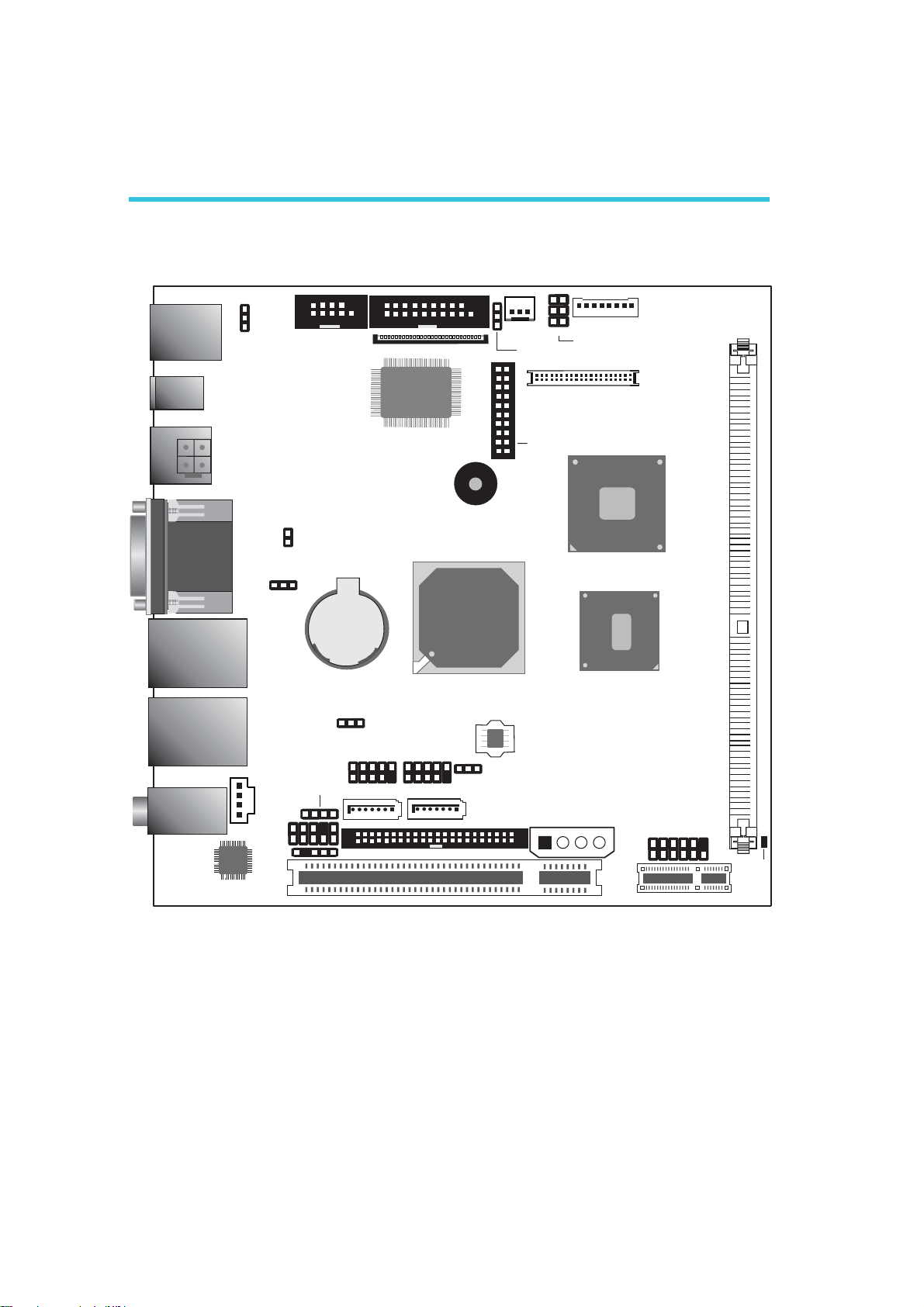
System Board Layout ..........................................................................................................
System Memory..........................................................................................................................
Jumper Settings............................................................................................................................
Rear Panel I/O Ports.............................................................................................................
I/O Connectors..........................................................................................................................
Chapter 3 - BIOS Setup......................................................................
Award BIOS Setup Utility.................................................................................................
Updating the BIOS..................................................................................................................
5
5
6
6
7
7
8
8
10
14
14
15
18
23
35
53
53
90
Chapter 4 - Supported Softwares.....................................................
Drivers for Windows 7 / Windows Vista System.....................................
Drivers for Windows XP System..............................................................................
Appendix A - NLITE and AHCI Installation Guide..........................
Appendix B - Watchdog Timer.............................................................
Appendix C - System Error Message...............................................
Appendix D - Troubleshooting..........................................................
92
93
115
129
141
145
147
Page 5

About this Manual
An electronic file of this manual is included in the CD. To view the
user’s manual in the CD, insert the CD into a CD-ROM drive. The
autorun screen (Main Board Utility CD) will appear. Click “User’s
Manual” on the main menu.
Warranty
1. Warranty does not cover damages or failures that arised from
misuse of the product, inability to use the product, unauthorized
replacement or alteration of components and product specifications.
2. The warranty is void if the product has been subjected to physical abuse, improper installation, modification, accidents or unauthorized repair of the product.
3. Unless otherwise instructed in this user’s manual, the user may
not, under any circumstances, attempt to perform service, adjustments or repairs on the product, whether in or out of warranty.
It must be returned to the purchase point, factory or authorized
service agency for all such work.
4. We will not be liable for any indirect, special, incidental or
consequencial damages to the product that has been modified
or altered.
Page 6

1
Introduction
Static Electricity Precautions
It is quite easy to inadvertently damage your PC, system board,
components or devices even before installing them in your system
unit. Static electrical discharge can damage computer components
without causing any signs of physical damage. You must take extra
care in handling them to ensure against electrostatic build-up.
1. To prevent electrostatic build-up, leave the system board in its
anti-static bag until you are ready to install it.
2. Wear an antistatic wrist strap.
3. Do all preparation work on a static-free surface.
4. Hold the device only by its edges. Be careful not to touch any of
the components, contacts or connections.
5. Avoid touching the pins or contacts on all modules and connectors. Hold modules or connectors by their ends.
Important:
Electrostatic discharge (ESD) can damage your processor,
disk drive and other components. Perform the upgrade instruction procedures described at an ESD workstation
only. If such a station is not available, you can provide
some ESD protection by wearing an antistatic wrist strap
and attaching it to a metal part of the system chassis. If a
wrist strap is unavailable, establish and maintain contact
with the system chassis throughout any procedures requiring ESD protection.
Safety Measures
To avoid damage to the system:
• Use the correct AC input voltage range
To reduce the risk of electric shock:
• Unplug the power cord before removing the system chassis
cover for installation or servicing. After installation or servicing,
cover the system chassis before plugging the power cord.
..
.
..
Battery:
• Danger of explosion if battery incorrectly replaced.
• Replace only with the same or equivalent type recommend
the manufacturer.
• Dispose of used batteries according to local ordinance.
6
by
Page 7

About the Package
The system board package contains the following items. If any of
these items are missing or damaged, please contact your dealer or
sales representative for assistance.
; The system board
; One IDE cable
; One USB cable
; One Serial ATA data cable
; One Serial ATA power cable
; One bracket mounted with a COM port
; One “Main Board Utility” CD
; One I/O shield
; A user’s manual
; One QR (Quick Reference)
Introduction
1
The system board and accessories in the package may not come
similar to the information listed above. This may differ in accordance
to the sales region or models in which it was sold. For more information about the standard package in your region, please contact
your dealer or sales representative.
Before Using the System Board
Before using the system board, prepare basic system components.
If you are installing the system board in a new system, you will need
at least the following internal components.
• A CPU
• Memory module
• Storage devices such as hard disk drive, CD-ROM, etc.
You will also need external system peripherals you intend to use
which will normally include at least a keyboard, a mouse and a video
display monitor.
7
Page 8

1
Introduction
Chapter 1 - Introduction
Specifications
Processor
Chipset
System Memory
Expansion Slots
Graphics
Audio
• Intel® AtomTM N270 (Diamondville SC) processor
• 1.6GHz core frequency, 1.10V voltage
• 2.5W thermal design power
• 512KB on-die second level cache
• 533-MT/s FSB
• 22x22 mm, 1.0 mm ball pitch and 437 balls FCBGA
®
• Intel
• One 240-pin DDR2 DIMM socket
• Maximum memory supports up to 2GB
• Supports 400MHz and 533MHz DDR2 SDRAM
• 1 PCI Express x1 slot
• 1 PCI slot
• 133/166MHz internal graphics core render frequency at 1.05V
• One SDVO port (Port B)
• Supports 18-bit dual-channel LVDS
• Supports CRT resolutions up to SXGA+
• Realtek ALC262 2-channel High Definition Audio
• 2x 6W for 8ohm speaker
• Two 24-bit stereo DACs and three 20-bit stereo ADCs
• S/PDIF input/output interface
chipset
- Northbridge: Intel® 945GSE GMCH
- Southbridge: Intel® 82801GBM ICH7M
core voltage
- SDVO slot reversal not supported
LAN
Serial ATA
IDE
BIOS
8
• Two Realtek RTL8111C PCI Express Gigabit controllers
• Supports 10Mbps, 100Mbps and 1Gbps data transmission
• IEEE 802.3 (10/100Mbps) and IEEE 802.3ab (1Gbps) compliant
• Two SATA ports with independent DMA operation supported
on ports 0 and 2
• Two-mode operation supports legacy mode using I/O space or
an AHCI mode using memory space
• SATA and PATA can be used in a combined function mode
(When SATA is used with PATA, AHCI mode is not suppor ted.)
• Bus Master IDE (PATA) controller
• Supports up to two IDE devices
• Ultra ATA 33
• Award BIOS
• 8Mbit SPI interface BIOS
Page 9

Introduction
1
Rear Panel I/O
Ports
I/O Connectors
• 1 mini-DIN-6 PS/2 mouse port
• 1 mini-DIN-6 PS/2 keyboard port
• 1 1-pin DC 12V jack
• 1 4-pin DC 12V jack or 4-pin ATX 12V power connector
(optional)
• 1 DB-9 serial port
• 1 DB-15 VGA port
• 2 RJ45 LAN ports
• 4 USB 2.0/1.1 ports
• Mic-in, line-in and line-out
• 2 connectors for 4 additional external USB 2.0/1.1 por ts
• 1 connector for an additional external serial por t
• 1 speaker-out connector with amplifying feature
• 1 SDVO connector for DFI NP1-LVDS (24-bit / 2 channels
external LVDS) or NP1-DVI (external DVI-D) daughterboard
• 1 LVDS LCD panel connector
• 1 LCD/inverter power connector
• 1 DIO connector
• 1 front audio connector for line-out and mic-in jacks
• 1 CD-in internal audio connector
• 1 S/PDIF connector
• 2 Serial ATA connectors
• 1 44-pin IDE connector
• 1 FDD connector (FPC type) - optional
• 1 4-pin power connector for the SATA drive
• 1 front panel connector
• 1 chassis intrusion connector
• 1 fan connector
Energy Efficient
Design
Damage Free
Intelligence
Temperature
Humidity
PCB
• Supports ACPI specification 2.0/1.0
• Supports ACPI STR (Suspend to RAM) function
• Wake-On-Events include:
- Wake-On-PS/2 Keyboard/Mouse
- Wake up by PCI card
- PCI Express PME
- USB KB/MS wake up from S3
- Wake-On-Ring
- RTC timer to power-on the system
• Enhanced Intel
• AC power failure recovery
• Monitors CPU/system temperature and overheat alarm
• Monitors CPU(V)/3.3V/5V/12V/VBAT(V) voltages and failure
alarm
• Monitors system fan speed and failure alarm
• Read back capability that displays temperature, voltage and fan
speed
• Watchdog timer function
o
•0
C to 60oC
• 10% to 90%
• 6-layers, Mini-ITX form factor
• 17cm (6.7") x 17cm (6.7")
®
SpeedStep Technology
9
Page 10

1
Introduction
Features
watchdog timer
the set time interval. If the system hangs or fails to function, it will
reset at the set time interval so that your system will continue to
operate.
DDR2
GB per second and beyond. That is twice the speed of the conventional DDR without increasing its power consumption. DDR2
SDRAM modules work at 1.8V supply compared to 2.6V memory
voltage for DDR modules. DDR2 also incorporates new innovations
such as the On-Die Termination (ODT) as well as larger 4-bit prefetch against DDR which fetches 2 bits per clock cycle.
graphics
Intel® Graphics Media Accelerator 950 architecture; delivering
sophisticated graphics for large display applications. Graphics
interfaces such as single-channel SDVO, VGA and dual-channel LVDS
support multiple graphics display options.
DDR2 is a higher performance DDR technology
whose data transfer rate delivers bandwidth of 4.3
The Intel
integrated 32-bit 3D graphics engine based on the
The Watchdog Timer function allows your
application to regularly “clear” the system at
®
945GSE Express Chipset features an
pci express
scale speeds by forming multiple lanes. The x1 PCI Express lane
supports transfer rate of 2.5 Gigabytes (250MBbps) per second
which is nearly 4 times faster than the traditional PCI.
S/PDIF
having to be converted first to an analog format. This prevents the
quality of the audio signal from degrading whenever it is converted
to analog. S/PDIF is usually found on digital audio equipment such as
a DAT machine or audio processing device. The S/PDIF connector on
the system board sends surround sound and 3D audio signal outputs to amplifiers and speakers and to digital recording devices like
CD recorders.
S/PDIF is a standard audio file transfer format that
transfers digital audio signals to a device without
PCI Express is a high bandwidth I/O
infrastructure that possesses the ability to
10
Page 11

Introduction
1
SERIAL ATA
150MB/s, it improves hard drive performance faster than the standard parallel ATA whose data transfer rate is 100MB/s.
gigabit lan
sion.
USB
while USB 2.0 supports 480Mb/second bandwidth providing a
marked improvement in device transfer speeds between your computer and a wide range of simultaneously accessible external Plug
and Play peripherals.
wake-on-ring
wake-up/power-on to respond to calls coming from an external modem or respond to calls from a modem PCI card that uses the PCI
PME (Power Management Event) signal to remotely wake up the
PC.
Serial ATA is a storage interface that is compliant
with SATA 1.0a specification. With speed of up to
The two Realtek RTL8111C PCI Express Gigabit
controllers support up to 1Gbps data transmis-
The system board supports USB 2.0 and USB 1.1
ports. USB 1.1 supports 12Mb/second bandwidth
This feature allows the system that is in the
Suspend mode or Soft Power Off mode to
Important:
The 5V_standby power source of your power supply must support ≥720mA.
wake-on-lan
It is supported via the onboard LAN port or via a PCI LAN card
that uses the PCI PME (Power Management Event) signal. However,
if your system is in the Suspend mode, you can power-on the system
only through an IRQ or DMA interrupt.
Important:
The 5V_standby power source of your power supply must support ≥720mA.
This feature allows the network to remotely
wake up a Soft Power Down (Soft-Off) PC.
11
Page 12

1
Introduction
wake-on-PS/2
tem.
Important:
The 5V_standby power source of your power supply must support ≥720mA.
wake-on-USB
from the S3 (STR - Suspend To RAM) state.
Important:
If you are using the Wake-On-USB Keyboard/Mouse function for
2 USB ports, the 5V_standby power source of your power supply must support ≥1.5A. For 3 or more USB ports, the
5V_standby power source of your power supply must support
≥
2A.
This function allows you to use the PS/2 keyboard or PS/2 mouse to power-on the sys-
This function allows you to use a USB keyboard or USB mouse to wake up a system
rtc timer
and time.
ACPI STR
fication. ACPI has energy saving features that enables PCs to implement Power Management and Plug-and-Play with operating systems
that support OS Direct Power Management. ACPI when enabled in
the Power Management Setup will allow you to use the Suspend to
RAM function.
With the Suspend to RAM function enabled, you can power-off the
system at once by pressing the power button or selecting “Standby”
when you shut down Windows
sometimes tiresome process of closing files, applications and operating system. This is because the system is capable of storing all programs and data files during the entire operating session into RAM
(Random Access Memory) when it powers-off. The operating session
The RTC installed on the system board allows your
system to automatically power-on on the set date
The system board is designed to meet the ACPI
(Advanced Configuration and Power Interface) speci-
®®
®
®®
without having to go through the
12
Page 13

Introduction
will resume exactly where you left off the next time you power-on
the system.
Important:
The 5V_standby power source of your power supply must support ≥720mA.
When power returns after an AC power fail-
Power failure
recovery
automatically.
ure, you may choose to either power-on the
system manually or let the system power-on
1
13
Page 14
2
Hardware Installation
Chapter 2 - Hardware Installation
System Board Layout
PS/2 Mouse
PS/2 KB
DC Jack
12V
1
(optional)
DC Jack 12V
COM 1
VGA
LAN 1
USB 1
USB 0
LAN 2
USB 3
USB 2
Mic-in
Line-in
Line-out
1
PS/2 power
select ( )JP1
ATX +12V
power
1
Realtek
ALC262
1
Chassis
open
1
USB 0-3 power
select (J )P2
Speaker-out
CD-in
Front
audio
1
1
S/PDIF
2
1
1
COM 2
9
Battery
1
USB 4-51USB 6-7
SATA 0
2
1
2
1
Winbond
W83627
USB 4-7 power
select (J )P4
1
1
DIO
FDD
Intel
ICH7M
SATA 2
PCI
1
1
1
19
1
20 19
21
Clear CMOS
(J )P5
IDE
1
System
fan
Power-on
select ( )JP6
SPI Flash
BIOS
44
43
56
12
40
39
LVDS LCD panel
SDVO
Peripheral power
1
Panel power
select ( )J15
Intel
945GSE
Intel
Atom N270
LCD/Inverter
power
2
1
1
Front panel
PCIE
DIMM
Standby
LED
14
Page 15
Warning:
.
.
.
.
.
.
.
.
.
.
.
.
.
.
.
.
Electrostatic discharge (ESD) can damage your system board, processor, disk drives, add-in boards, and other components. Perform the
upgrade instruction procedures described at an ESD workstation only.
If such a station is not available, you can provide some ESD protection by wearing an antistatic wrist strap and attaching it to a metal
part of the system chassis. If a wrist strap is unavailable, establish
and maintain contact with the system chassis throughout any procedures requiring ESD protection.
System Memory
Warning:
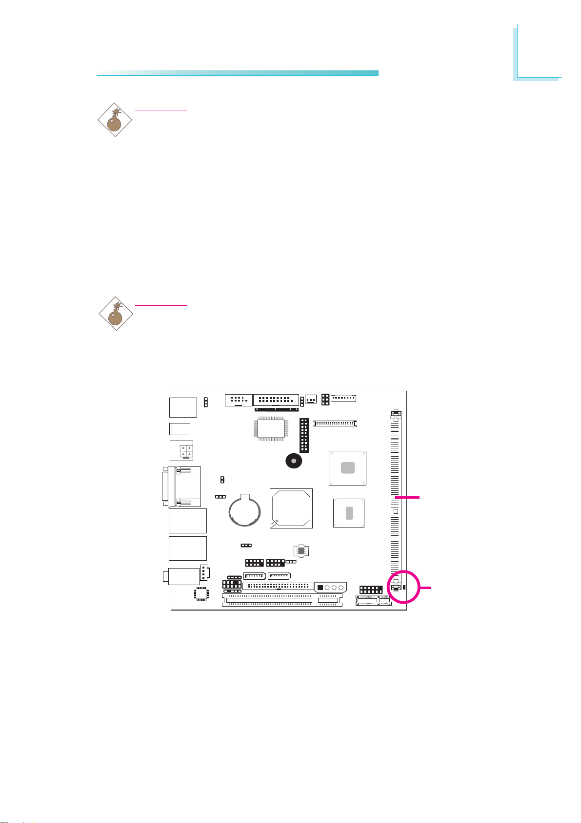
When the Standby LED lit red, it indicates that there is power on the
system board. Power-off the PC then unplug the power cord prior to
installing any devices. Failure to do so will cause severe damage to
the motherboard and components.
Hardware Installation
2
DIMM
Standby LED
The system board supports one 240-pin DDR2 DIMM socket.
15
Page 16
2
Hardware Installation
Installing the DIM Module
Note:
The system board used in the following illustrations may not
resemble the actual board. These illustrations are for reference
only.
1. Make sure the PC and all other peripheral devices connected to
it has been powered down.
2. Disconnect all power cords and cables.
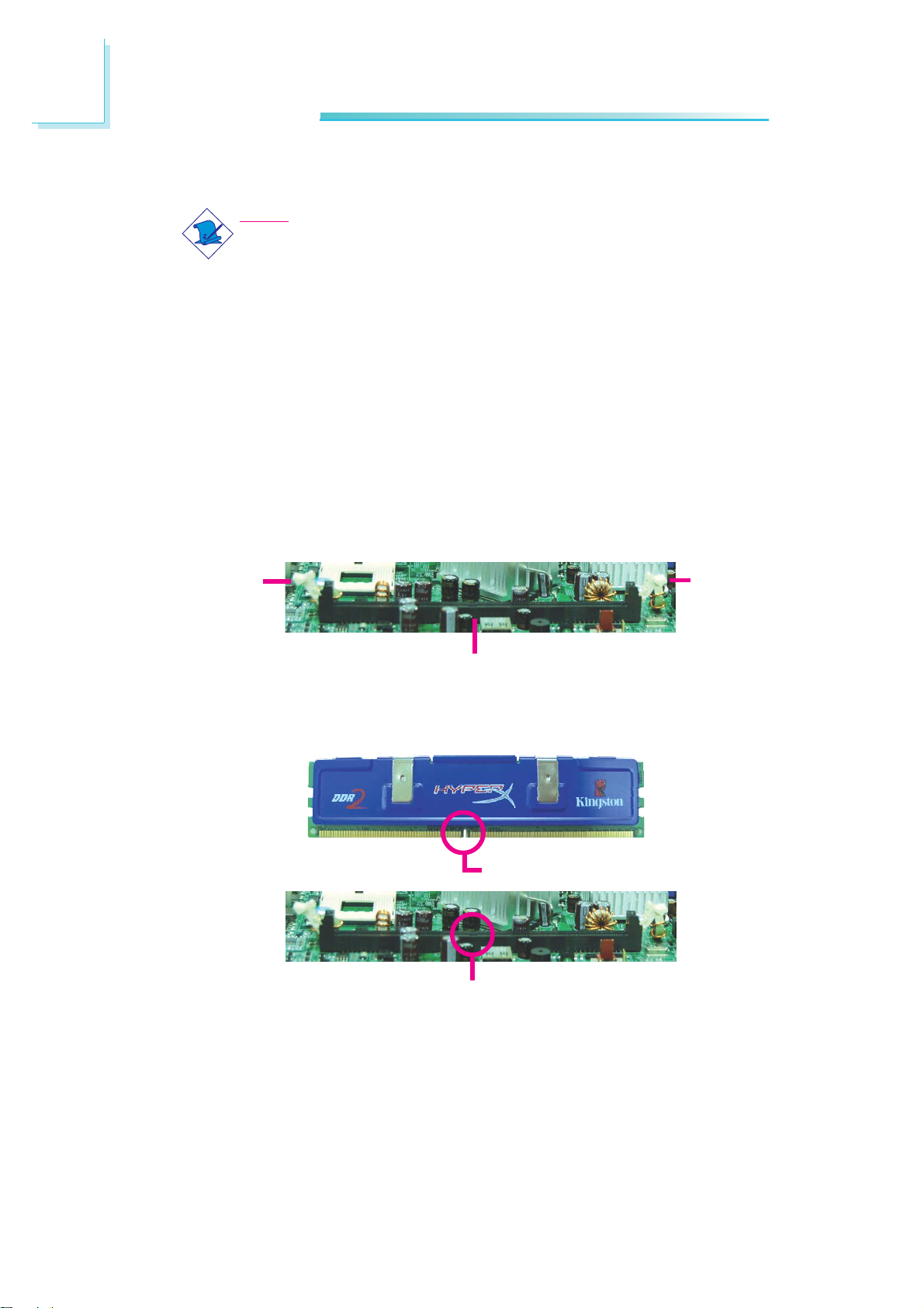
3. Locate the DDR2 socket on the board.
4. Push the “ejector tabs” which are at the ends of the socket to
the side.
Ejector
tab
DDR2 socket
5. Note how the module is keyed to the socket.
Notch
Key
Ejector
tab
16
Page 17
Hardware Installation
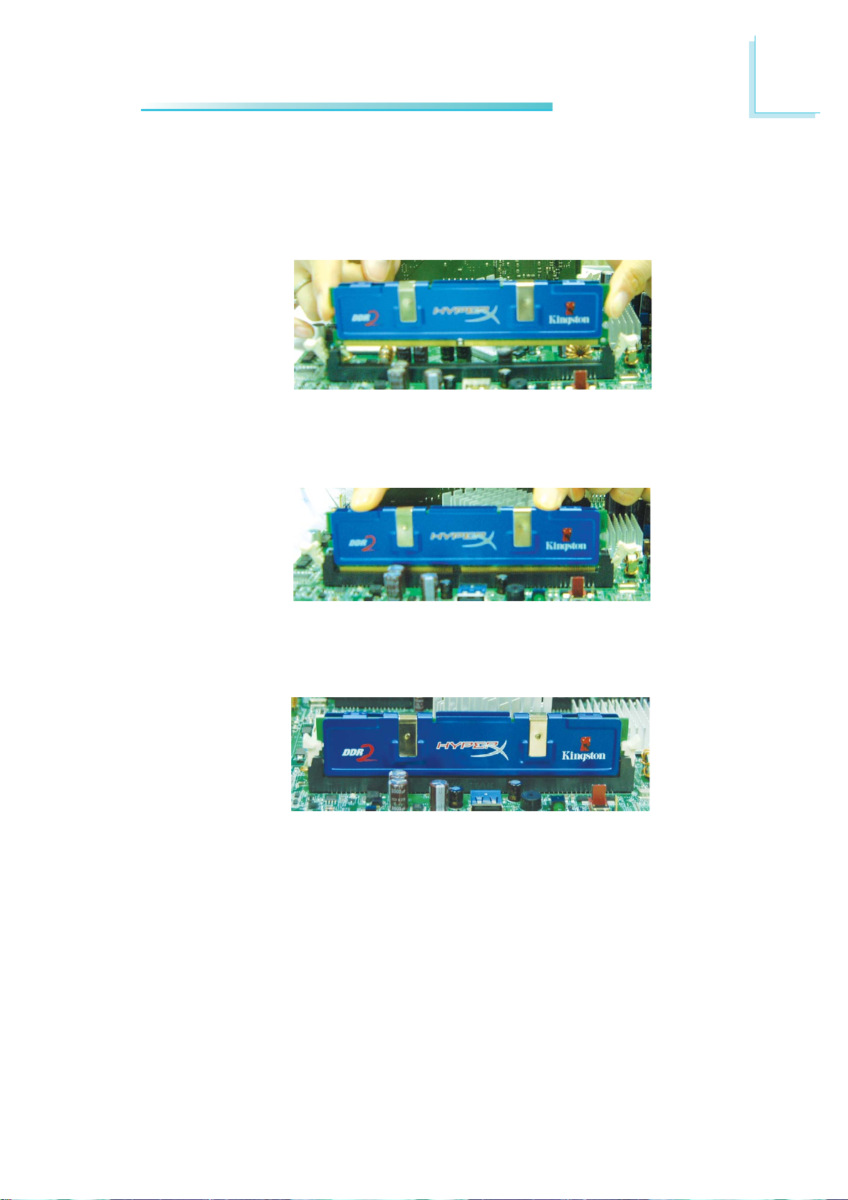
6. Grasping the module by its edges, position the module above
the socket with the “notch” in the module aligned with the “key”
on the socket. The keying mechanism ensures the module can be
plugged into the socket in only one way.
7. Seat the module vertically, pressing it down firmly until it is completely seated in the socket.
2
8. The ejector tabs at the ends of the socket will automatically
snap into the locked position to hold the module in place.
17
Page 18
2
Hardware Installation
Jumper Settings
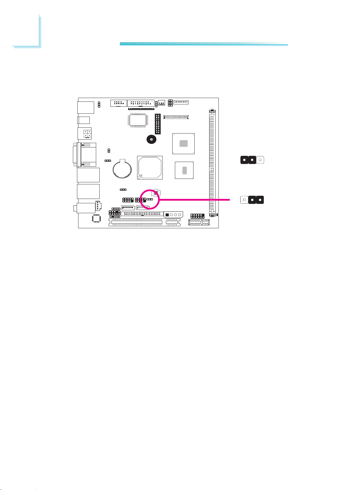
Clear CMOS Data
31
2
1-2 On: Normal
(default)
JP5
312
X
2-3 On:
Clear CMOS Data
If you encounter the following,
a) CMOS data becomes corrupted.
b) You forgot the supervisor or user password.
you can reconfigure the system with the default values stored in the
ROM BIOS.
To load the default values stored in the ROM BIOS, please follow
the steps below.
1. Power-off the system and unplug the power cord.
2. Set JP5 pins 2 and 3 to On. Wait for a few seconds and set JP5
back to its default setting, pins 1 and 2 On.
18
3. Now plug the power cord and power-on the system.
Page 19
PS/2 Power Select
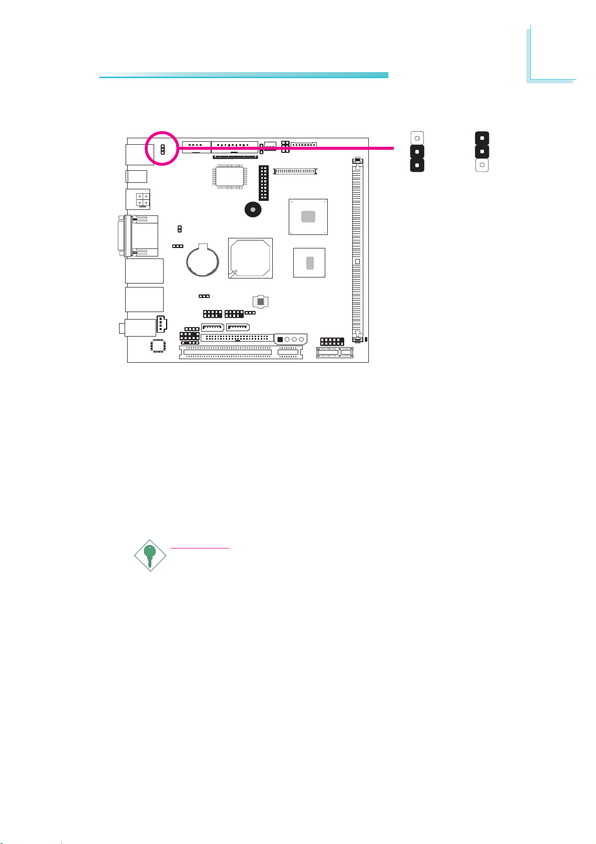
Hardware Installation
2
JP1
X
1-2 On: 5V
(default)
3
2
1
5V_standby
3
2
1
2-3 On:
JP1 is used to select the power of the PS/2 keyboard/mouse port.
Selecting 5V_standby will allow you to use the PS/2 keyboard or
PS/2 mouse to wake up the system.
BIOS Setting
Configure the PS/2 keyboard/mouse wake up function in the Integrated Peripherals submenu (“Super IO Device” section) of the BIOS.
Refer to chapter 3 for more information.
Important:
The 5V_standby power source of your power supply must support ≥720mA.
19
Page 20
2
Hardware Installation
USB Power Select
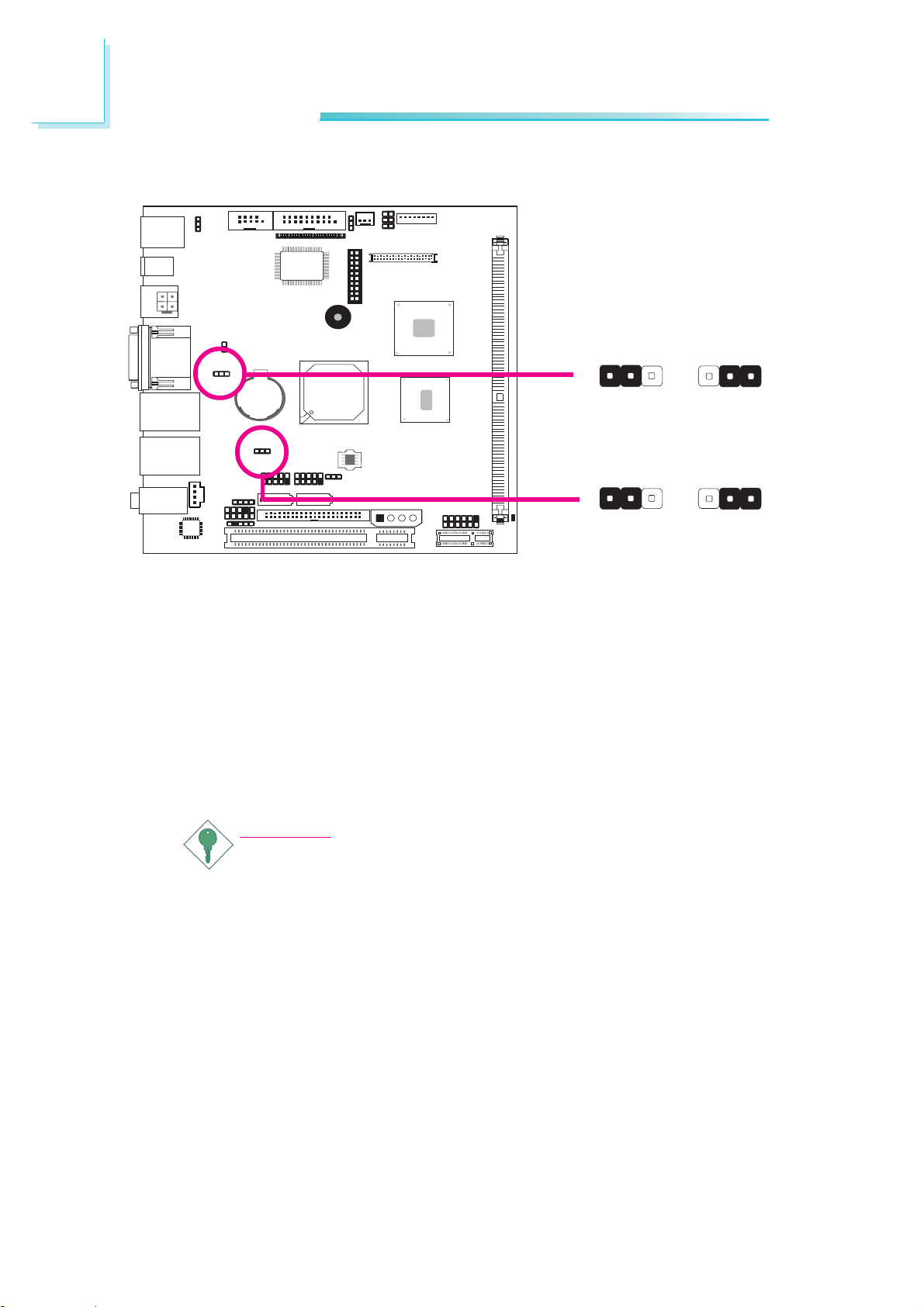
USB 0-3
(JP2)
31
2
312
X
USB 4-7
(JP4)
1-2 On: 5V
(default)
31
2
2-3 On:
5V_standby
312
X
1-2 On: 5V
(default)
JP2 (for USB 0-3) and JP4 (for USB 4-7) are used to select the
power of the USB ports. Selecting 5V_standby will allow you to use
a USB device to wake up the system.
BIOS Setting
“USB KB Wake-Up From S3” in the Power Management Setup
submenu of the BIOS must be set to Enabled. Refer to chapter 3
for more information.
2-3 On:
5V_standby
20
Important:
If you are using the Wake-On-USB Keyboard/Mouse function for
2 USB ports, the 5V_standby power source of your power supply must support ≥1.5A. For 3 or more USB ports, the
5V_standby power source of your power supply must support
≥
2A.
Page 21
Panel Power Select
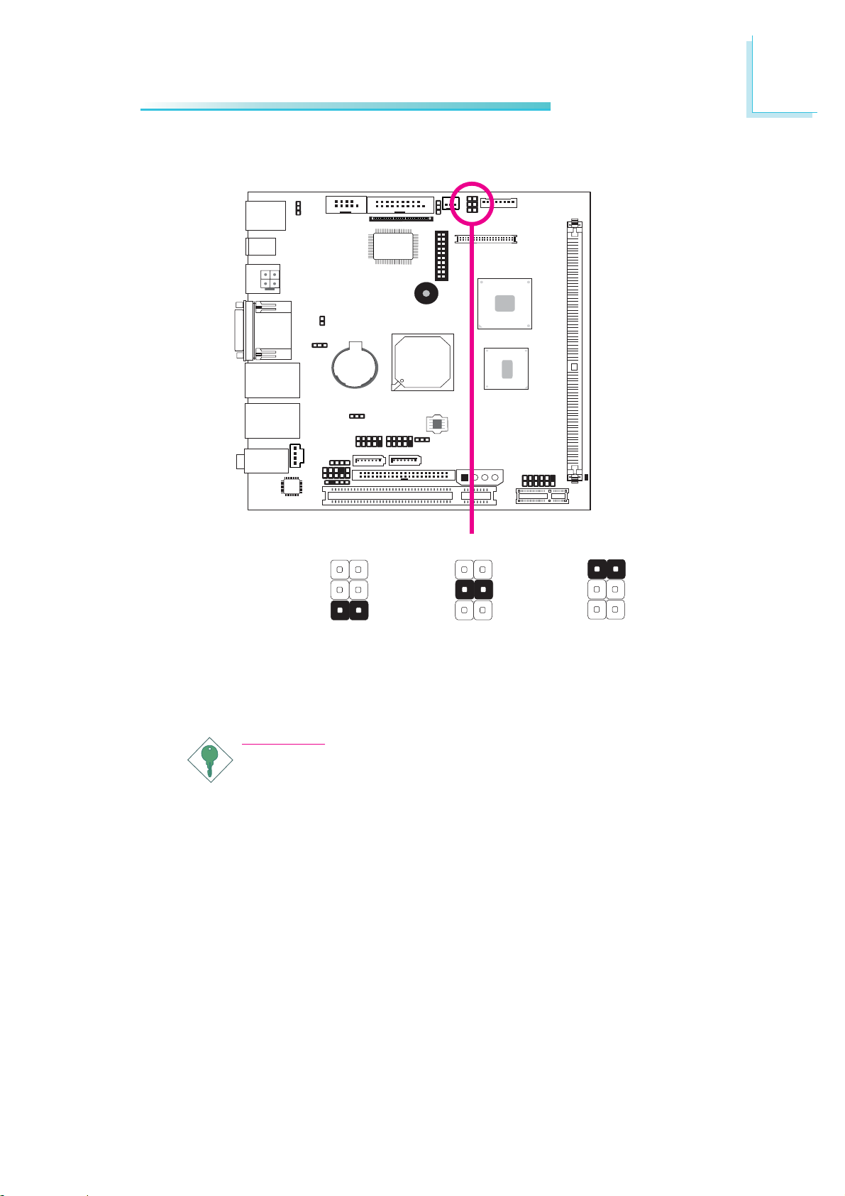
Hardware Installation
2
J15
X
6
4
2
1-2 On: 12V
5
3
1
6
4
2
3-4 On: 5V 5-6 On: 3.3V
5
3
1
6
4
2
(default)
5
3
1
J15 is used to select the power supplied to the LCD panel.
Important:
Before powering-on the system, make sure J15’s setting
matches the LCD panel’s specification. Selecting the incorrect
voltage will seriously damage the LCD panel.
21
Page 22
2
Hardware Installation
Power-on Select
JP6
X
Power-on via
power button
1
2
3
1-2 On:
(default)
1
2
3
2-3 On:
Power-on via
AC power
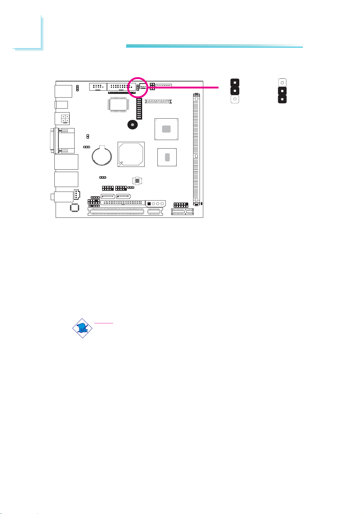
JP6 is used to select the method of powering on the system. If you
want the system to power-on whenever AC power comes in, set
JP6 pins 2 and 3 to On. If you want to use the power button, set
pins 1 and 2 to On.
When using JP6 “Power On” feature to power the system back on
after a power failure occurs, may not power on the system if the
power lost is resumed within 5 seconds (power flicker).
Note:
In order to ensure that power is resumed after a power failure
that may occur within a 5 second period, JP6 should be set to
pins 2-3 and the “PWRON After PWR-Fail” in CMOS is set to
“Power On”.
22
Page 23
Rear Panel I/O Ports
Hardware Installation
2
PS/2
Mouse
PS/2
K/B
4-pin
DC 12V
1-pin
DC 12V
4-pin DC 12V jack or a
4-pin ATX 12V power (optional)
VGA
LAN 1COM 1
USB 0-1 USB 2-3
LAN 2
Mic-in
Line-in
Line-out
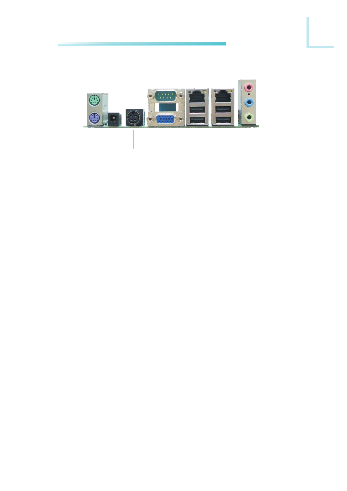
The rear panel I/O ports consist of the following:
• PS/2 mouse port
• PS/2 keyboard port
• 1-pin DC 12V jack
• 4-pin DC 12V jack or 4-pin ATX 12V power connector
• COM port
• VGA port
• 2 LAN ports
• 4 USB ports
• Mic-in jack
• Line-in jack
• Line-out jack
23
Page 24
2
.
.
.
.
.
.
.
.
Hardware Installation
PS/2 Mouse and PS/2 Keyboard Ports
PS/2 Mouse
PS/2 Keyboard
W
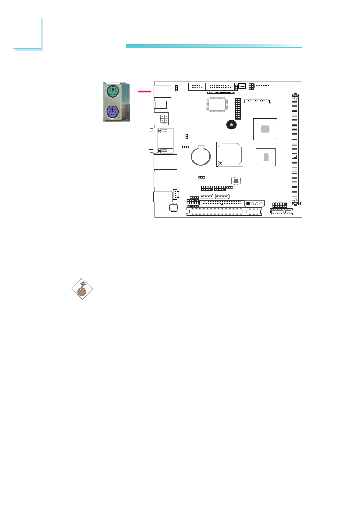
These ports are used to connect a PS/2 mouse and a PS/2 keyboard. The PS/2 mouse port uses IRQ12. If a mouse is not connected to this port, the system will reser ve IRQ12 for other expansion cards.
Warning:
Make sure to turn off your computer prior to connecting or
disconnecting a mouse or keyboard. Failure to do so may damage the system board.
Wake-On-PS/2 Keyboard/Mouse
The Wake-On-PS/2 Keyboard/Mouse function allows you to use the
PS/2 keyboard or PS/2 mouse to power-on the system. To use this
function:
• Jumper Setting:
JP1 must be set to “2-3 On: 5V_standby”. Refer to “PS/2 Power
Select” in this chapter for more information.
24
Page 25

Hardware Installation
• BIOS Setting:
Configure the PS/2 keyboard/mouse wake up function in the Integrated Peripherals submenu (“Super IO Device” section) of the
BIOS. Refer to chapter 3 for more information.
Important:
The 5V_standby power source of your power supply must support ≥720mA.
2
25
Page 26
2
Hardware Installation
DC 12V Jack / ATX 12V Power
W
4-pin
1-pin
DC 12V
+12V
DC 12V
12
GroundGround
+12V
3
4
ATX 12V power
W
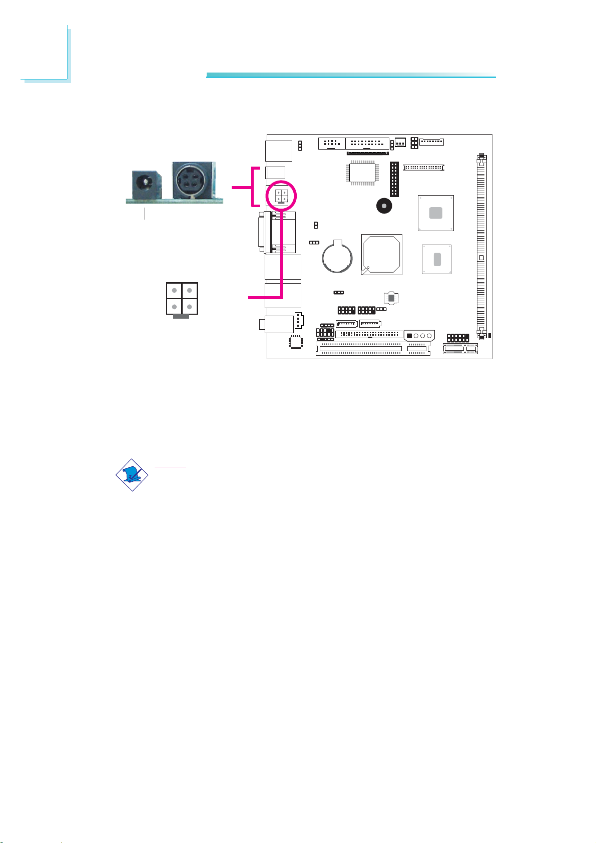
The system board comes standard with the 1-pin DC 12V jack.
Beside this jack, the system board may come equipped with either
an optional 4-pin DC 12V jack or a 4-pin ATX 12V power
connector.
Note:
-12V power is optional.
1-pin DC 12V jack
This jack provides maximum of 60W power and is considered a
low power solution. The recommended system configuration for this
power jack includes a CPU, one HDD and a CD-ROM.
4-pin DC 12V jack
This optional jack provides 60W to 84W power. The recommended
system configuration for this power jack includes a high speed CPU
(more than 1GHz), one HDD and a CD-ROM.
26
Page 27

Hardware Installation
ATX 12V Power
This optional jack provides 100W to 150W power and is capable
of providing the maximum power requirement. The recommended
system configuration includes a high speed CPU (more than 1GHz),
HDD, CD-ROM, USB devices and an add-in card.
Important:
Every power supply has its minimum load of power. If you use
a greater than 150W power supply, the power consumed by
the system board may not attain its minimum load causing
instability to the entire system.
2
27
Page 28
2
Hardware Installation
Serial (COM) Port
DSR-
RD
DTR-
CTS-
COM 2
COM 1
2
1
12345
TD
DCD-
RD
DCD-
6 7 8 9
RTS-
DSR-
GND
TD
DTR-
RI-
CTS-
RI-
RTS-
GND
9
W
W
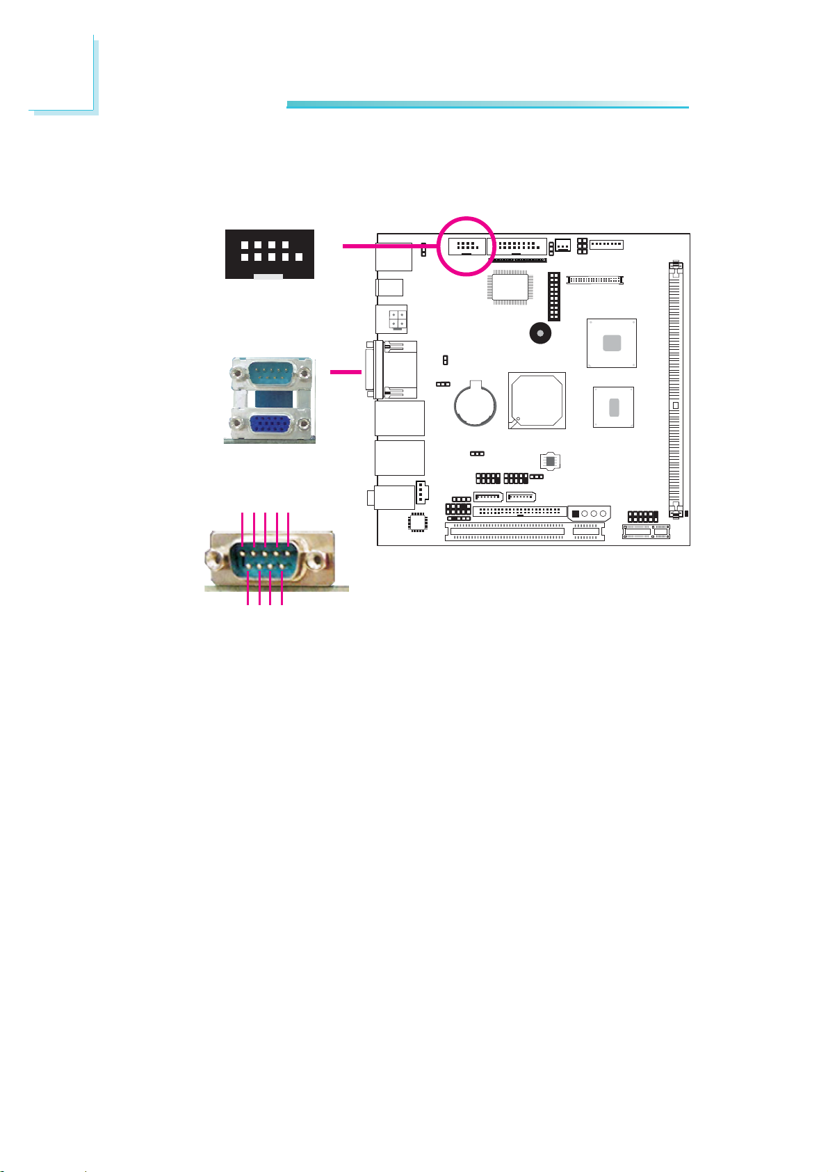
The system board is equipped with an onboard serial port (COM
1). It is also equipped with a 9-pin connector (COM 2). These serial
ports are RS-232 asynchronous communication ports with
16C550A-compatible UARTs that can be used with modems, serial
printers, remote display terminals, and other serial devices.
Your COM port may come mounted on a card-edge bracket. Install
the card-edge bracket to an available slot at the rear of the system
chassis then insert the serial port cable to COM 2. Make sure the
colored stripe on the ribbon cable is aligned with pin 1 of COM 2. .
BIOS Setting
Configure the serial ports in the Integrated Peripherals submenu
(“Super IO Device” section) of the BIOS. Refer to chapter 3 for
more information.
28
Page 29
VGA Port
VGA
Hardware Installation
2
W
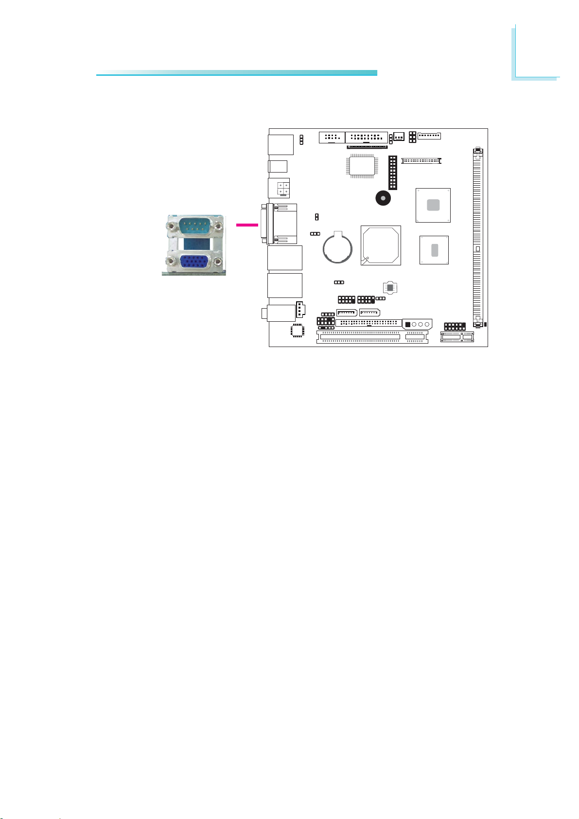
The VGA port is used for connecting a VGA monitor. Connect the
monitor’s 15-pin D-shell cable connector to the VGA port. After you
plug the monitor’s cable connector into the VGA port, gently tighten
the cable screws to hold the connector in place.
BIOS Setting
Configure the onboard VGA in the Advanced Chipset Features
submenu of the BIOS. Refer to chapter 3 for more information.
Driver Installation
Install the graphics driver. Refer to chapter 4 for more information.
29
Page 30
2
Hardware Installation
RJ45 Fast-Ethernet Ports
LAN 1
W
LAN 2
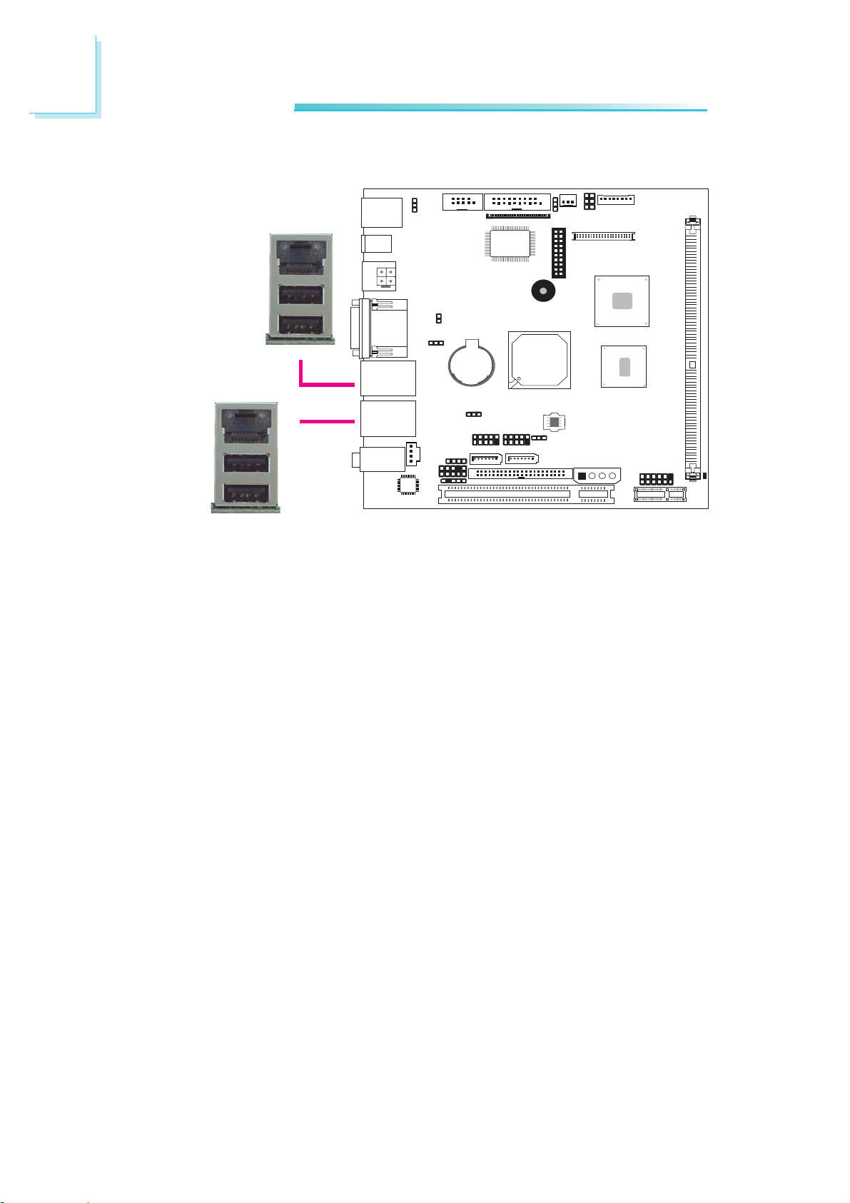
The LAN ports allow the system board to connect to a local area
network by means of a network hub.
BIOS Setting
Configure the onboard LAN ports in the Integrated Peripherals
submenu (“Onboard Device” section) of the BIOS. Refer to chapter
3 for more information.
Driver Installation
Install the LAN drivers. Refer to chapter 4 for more information.
W
30
Page 31
Universal Serial Bus Connectors
USB 1
USB 0
W
USB 3
USB 2
W
Hardware Installation
2
USB 4-5
USB 6-7
-Data
+Data
-Data
+Data
GND
N. C.
10
Key
GND
W
9
VCC
2
1
VCC
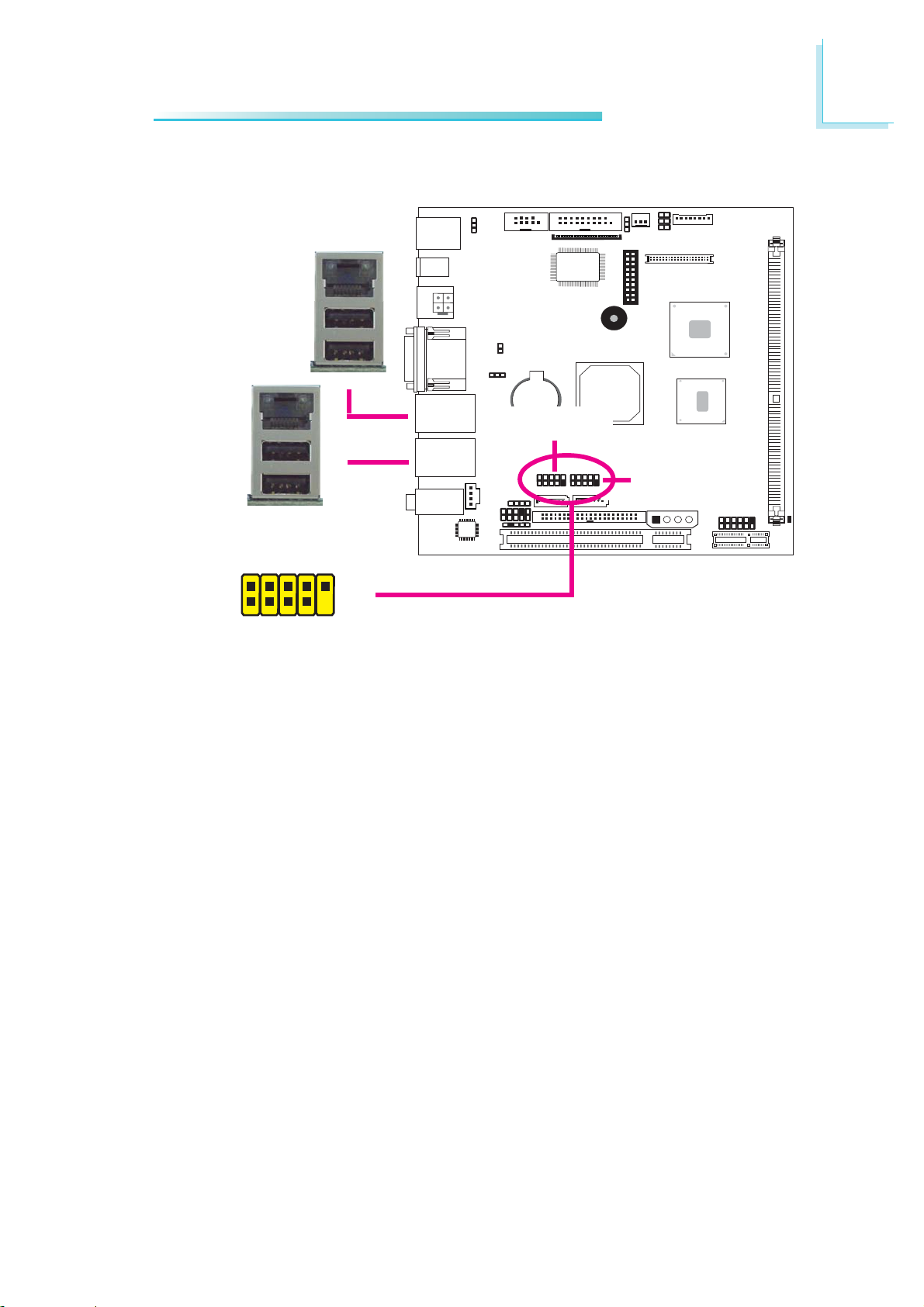
USB allows data exchange between your computer and a wide
range of simultaneously accessible external Plug and Play peripherals.
The system board is equipped with four onboard USB 2.0/1.1 ports.
The USB 4-5 and USB 6-7 connectors allow you to connect 4
additional USB 2.0/1.1 ports. The additional USB ports may be
mounted on a card-edge bracket. Install the card-edge bracket to an
available slot at the rear of the system chassis then insert the USB
port cables to a connector.
BIOS Setting
Configure the onboard USB in the Integrated Peripherals submenu
(“USB Device Setting” section) of the BIOS. Refer to chapter 3 for
more information.
31
Page 32

2
Hardware Installation
Driver Installation
You may need to install the proper drivers in your operating system
to use the USB device. Refer to your operating system’s manual or
documentation for more information.
Wake-On-USB Keyboard/Mouse
The Wake-On-USB Keyboard/Mouse function allows you to use a
USB keyboard or USB mouse to wake up a system from the S3
(STR - Suspend To RAM) state. To use this function:
• Jumper Setting:
JP2 and/or JP4 must be set to “2-3 On: 5V_standby”. Refer to
“USB Power Select” in this chapter for more information.
• BIOS Setting:
“USB KB Wake-Up From S3” in the Power Management Setup
submenu of the BIOS must be set to Enabled. Refer to chapter
3 for more information.
Important:
If you are using the Wake-On-USB Keyboard/Mouse function for
2 USB ports, the 5V_standby power source of your power supply must support ≥1.5A. For 3 or more USB ports, the
5V_standby power source of your power supply must support
≥
2A.
32
Page 33
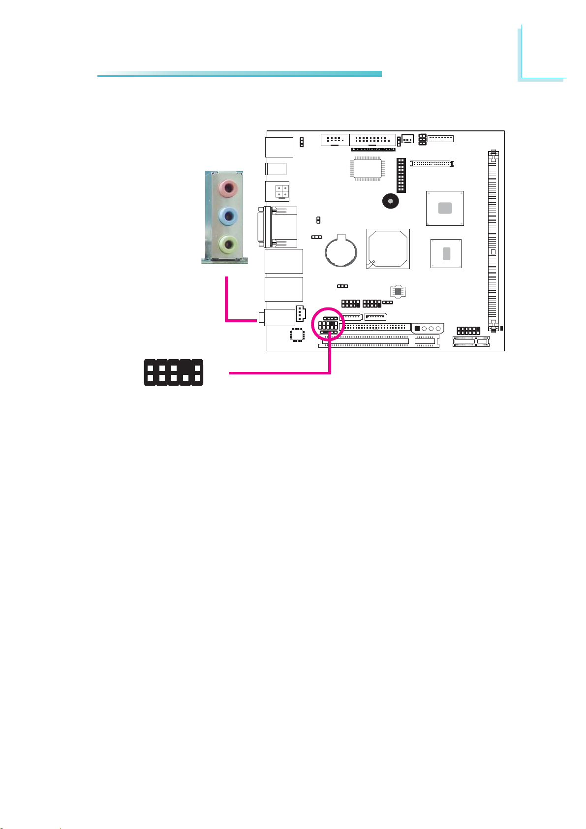
Audio
Hardware Installation
2
Rear audio
Mic-in
Line-in
Line-out
W
GND
Mic2-JD
Line2-JD
Key
10
W
9
Line2-L
Line2-R
Front_IO_Sense
Front audio
2
1
N.C.
Mic2-L
Mic2-R
Rear Audio
The system board is equipped with 3 audio jacks. A jack is a onehole connecting interface for inserting a plug.
• Mic-in Jack (Pink)
This jack is used to connect an external microphone.
• Line-in Jack (Light Blue)
This jack is used to connect any audio devices such as Hi-fi set,
CD player, tape player, AM/FM radio tuner, synthesizer, etc.
• Line-out Jack (Lime)
This jack is used to connect a headphone or external speakers.
33
Page 34

2
Hardware Installation
Front Audio
The front audio connector allows you to connect to the second lineout and mic-in jacks that are at the front panel of your system.
BIOS Setting
Configure the onboard audio in the Integrated Peripherals submenu
(“Onboard Device” section) of the BIOS. Refer to chapter 3 for
more information.
Driver Installation
Install the audio driver. Refer to chapter 4 for more information.
34
Page 35
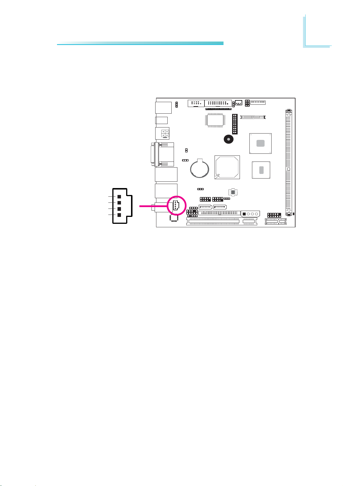
I/O Connectors
CD-in Internal Audio Connector
4
Right audio channel
Ground
Ground
Left audio channel
W
Hardware Installation
2
1
The CD-in connector is used to receive audio from a CD-ROM
drive, TV tuner or MPEG card.
35
Page 36
2
Hardware Installation
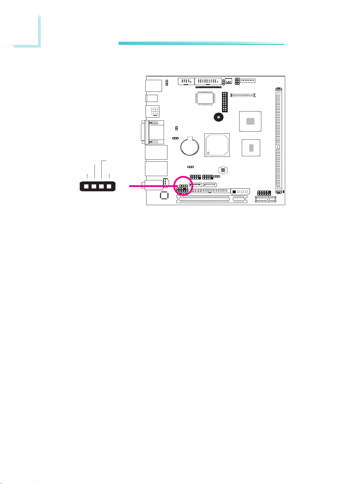
Speaker-out Connector
Out L-Out R+
Out L+Out R-
1
The speaker-out connector which has amplifying feature is used to
connect external speakers.
4
W
36
Page 37
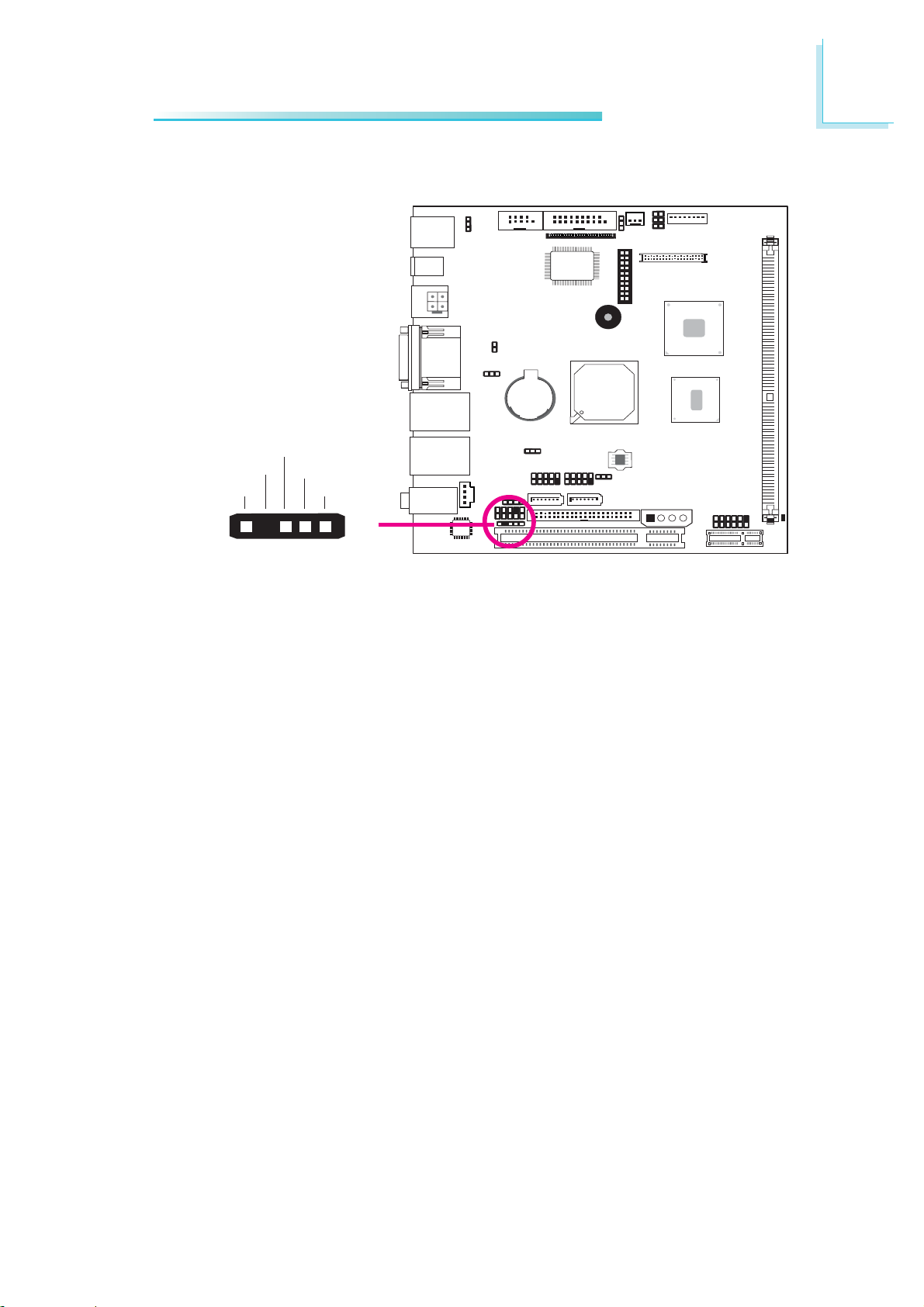
S/PDIF Connector
SPDIF out
Key
GND
+5V
SPDIF in
Hardware Installation
2
15
The S/PDIF connector is used to connect an external S/PDIF port.
Your S/PDIF port may be mounted on a card-edge bracket. Install
the card-edge bracket to an available slot at the rear of the system
chassis then connect the audio cable connector to the S/PDIF connector. Make sure pin 1 of the audio cable connector is aligned with
pin 1 of the S/PDIF connector.
W
37
Page 38
2
Hardware Installation
LVDS LCD Panel Connector
LCD/Inverter Power Connector
X
1
LCD/Inverter
Power
40
8
X
39
LVDS LCD Panel
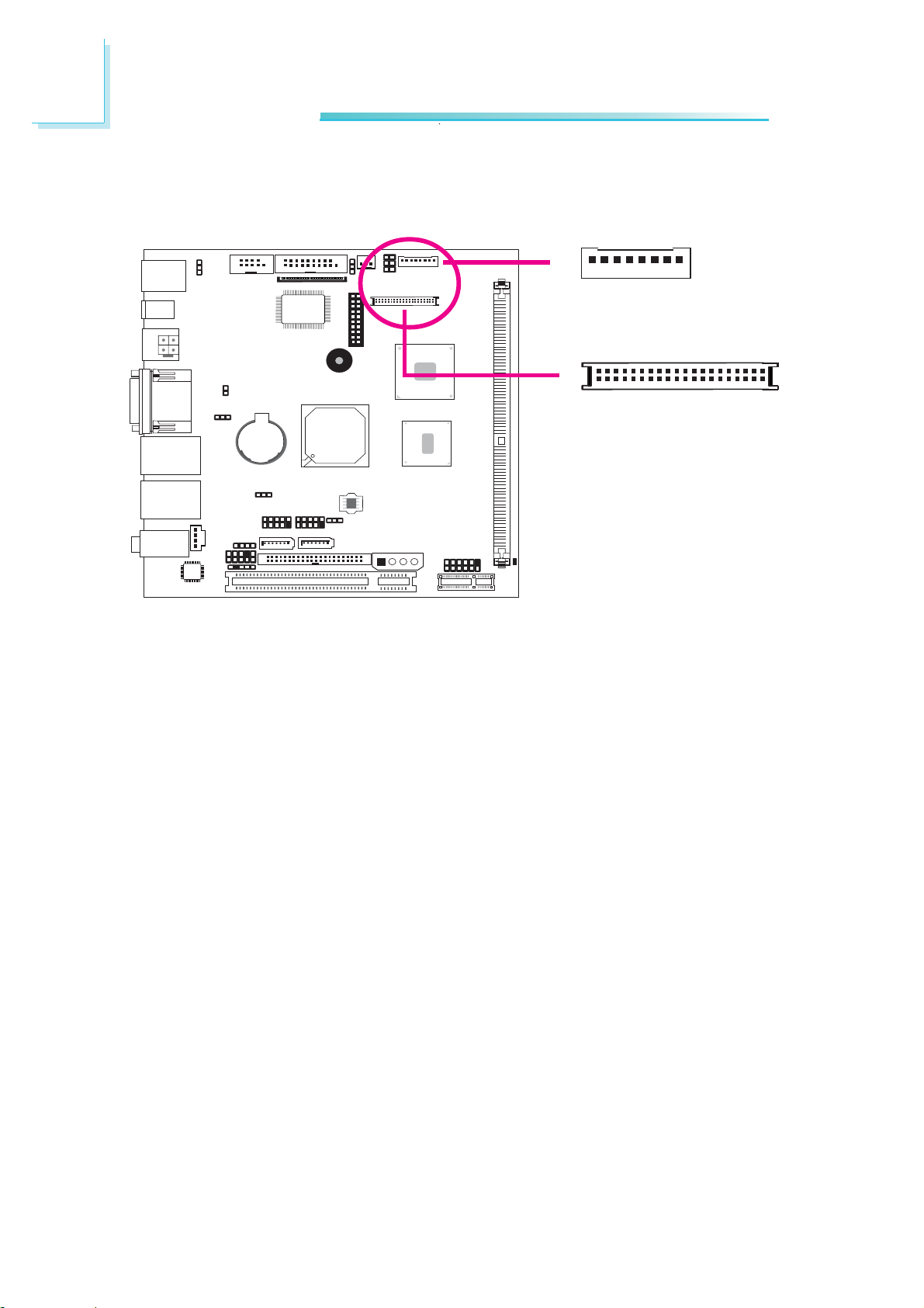
The system board allows you to connect a LCD Display Panel by
means of the LVDS LCD panel connector and the LCD/Inverter
power connector. These connectors transmit video signals and power
from the system board to the LCD Display Panel.
2
1
Refer to the next page for the pin functions of these connectors.
BIOS Setting
Configure the LCD panel in the Advanced Chipset Features
submenu of the BIOS. Refer to chapter 3 for more information.
38
Page 39

LVDS LCD Panel Connector
Hardware Installation
2
Pins
1
3
5
7
9
11
13
15
17
19
21
23
25
27
29
Function
GND
N. C.
N. C.
GND
LVDS_Out2+
LVDS_Out2-
GND
LVDS_Out1+
LVDS_Out1-
GND
LVDS_Out0+
LVDS_Out0-
GND
LVDS_CLK1+
LVDS_CLK1-
Pins
2
4
6
8
10
12
14
16
18
20
22
24
26
28
30
Function
GND
N. C.
N. C.
GND
LVDS_Out6+
LVDS_Out6-
GND
LVDS_Out5+
LVDS_Out5-
GND
LVDS_Out4+
LVDS_Out4-
GND
LVDS_CLK2+
LVDS_CLK2-
31
33
35
37
39
LCD/Inverter Power Connector
Pins
8
7
6
Panel Backlight On/Off Control
5
Function
+12V
+12V
+3.3V
GND
LVDS_DDCCLK
LVDS_DDCDAA
Panel Power
Panel Power
Pins
32
34
36
38
40
4
3
Panel Inverter Brightness Voltage Control
2
1
GND
N. C.
N. C.
Panel Power
Panel Power
Function
Panel Power
GND
GND
39
Page 40
2
Hardware Installation
SDVO Connector
PLT_RST-
SDVO_DATA
SDVO_CLK
ENABKL
ENAVDD
SDVO_FLDSTALL-
X
SDVO_FLDSTALL+
SDVO_INIT-
SDVO_INIT+
5V
1920
GND
GND
SDVOB_CLKSDVOB_CLK+
SDVOB_BLUESDVOB_BLUE+
SDVOB_GREENSDVOB_GREEN+
SDVOB_REDSDVOB_RED+
12
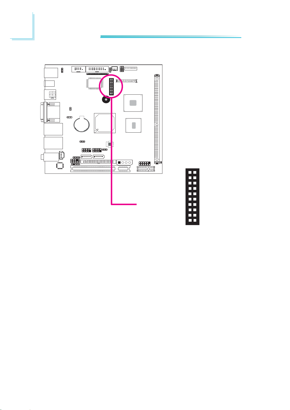
The SDVO connector is used to install a DFI NP1-LVDS (24-bit / 2
channels external LVDS) or NP1-DVI (external DVI-D)
daughterboard. These daughterboards come equipped with LVDS or
DVI interface allowing you to connect external display devices.
NP101-D16C comes standard with a BIOS that supports only the
NP1-DVI daughterboard.
If you intend to use the NP1-LVDS daughterboard, please take note
of the following:
1. It will not support the onboard LVDS.
2. A customized BIOS is required to support the NP1-LVDS
daughterboard.
BIOS Setting
Configure the LCD panel in the Advanced Chipset Features
submenu of the BIOS. Refer to chapter 3 for more information.
40
Page 41
Digital I/O Connector
Hardware Installation
2
X
1
2
19
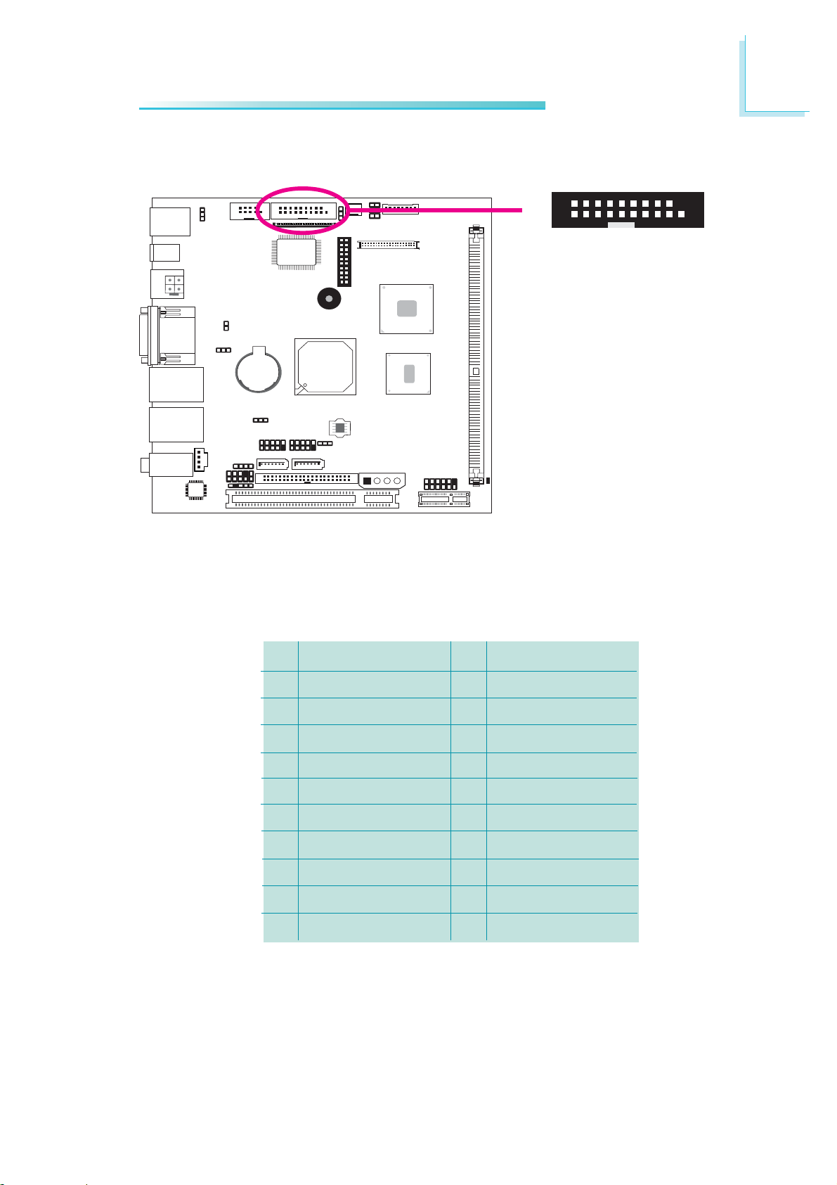
The Digital I/O connector provides powering-on function to an external device that is connected to this connector.
Digital I/O Connector
Pins
1
3
5
7
9
11
13
15
17
19
Function
GND
DIO7
DIO6
DIO5
DIO4
DIO3
DIO2
DIO1
DIO0
GND
Pins
2
4
6
8
10
12
14
16
18
Function
+12V
+12V
GND
VCC
VCC
GND
V_5P0_STBY
V_5P0_STBY
GND
41
Page 42
2
Hardware Installation
Serial ATA Connectors and Peripheral Power Connector
GroundGround
+5V+12V
4
SATA 0
SATA 2
1
X
Peripheral power
TXP
GND
1
7
RXP
TXN
RXN
GND
GND
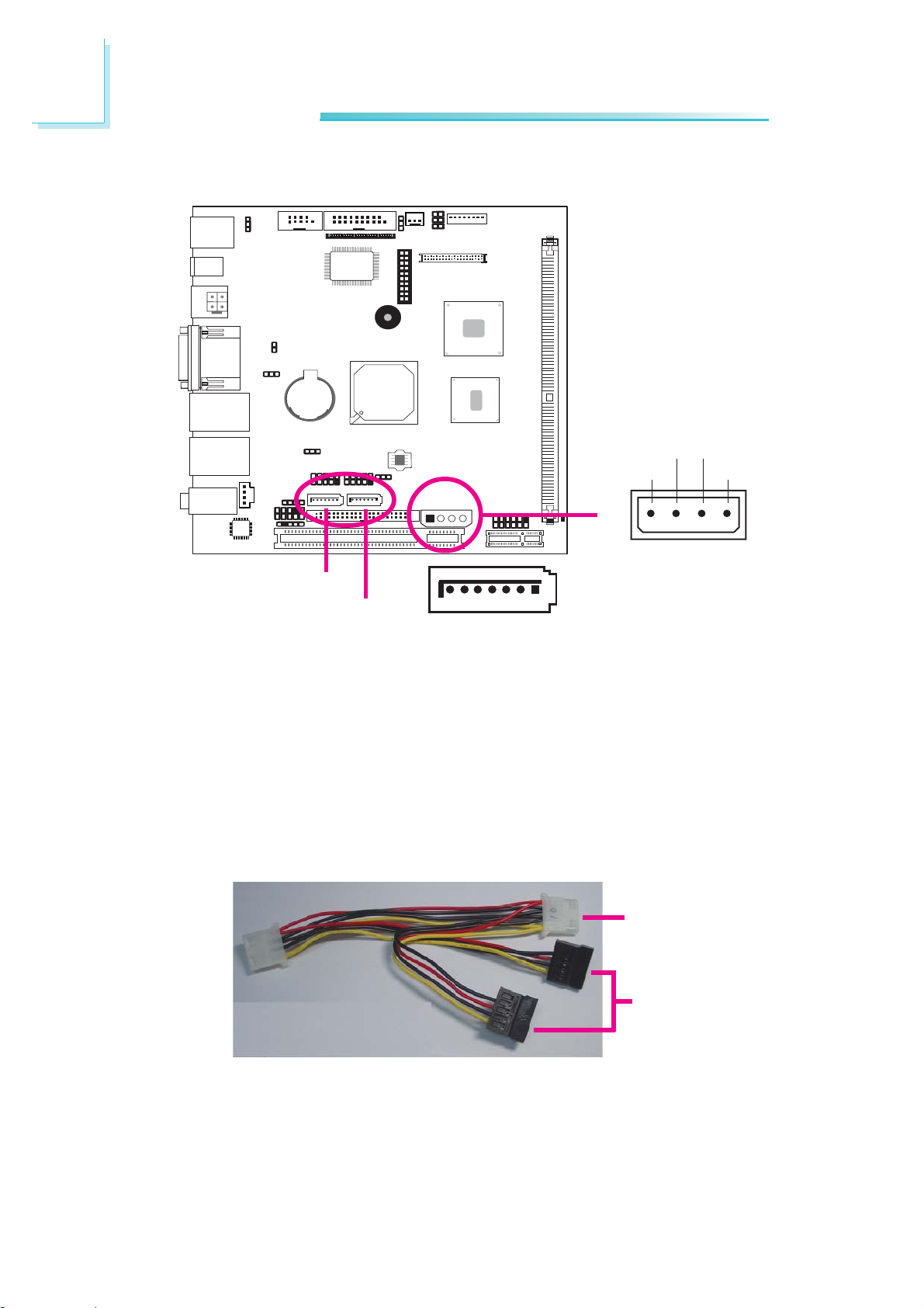
The Serial ATA connectors are used to connect Serial ATA devices.
Connect one end of the Serial ATA data cable to a SATA connector
and the other end to your Serial ATA device.
The system board package also comes with a power cable that
must be connected from the system board to the SATA drive’s
power connector in order to provide power to the drive.
Connect to the
peripheral power
connector
42
Connect to SATA
drives
BIOS Setting
Configure the Serial ATA drives in the Integrated Peripherals
submenu (“OnChip IDE Device” section) of the BIOS. Refer to
chapter 3 for more information.
Page 43
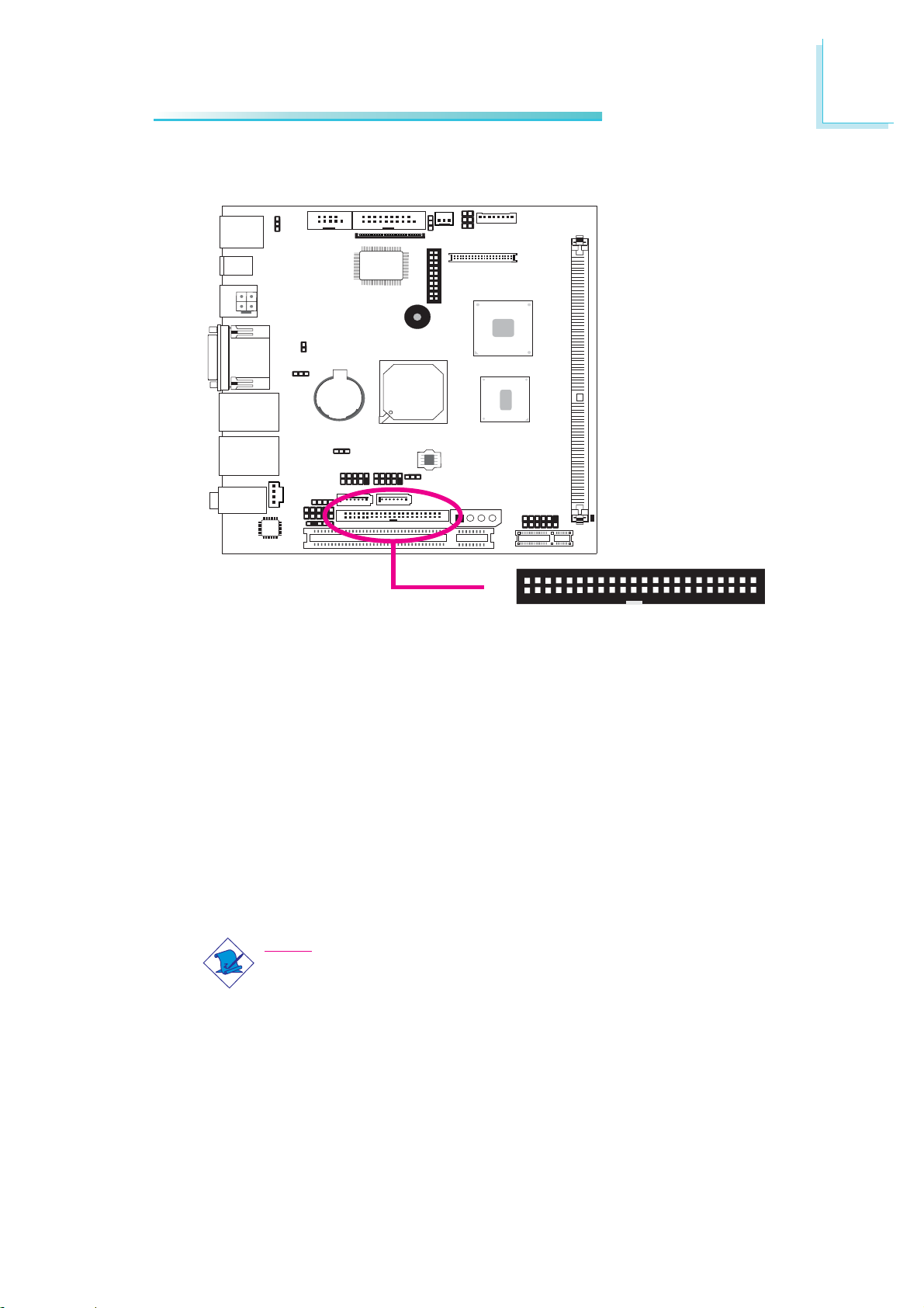
IDE Disk Drive Connectors
Hardware Installation
2
2
X
143
The IDE connector is used to connect hard drives. The connector on
the IDE cable can be inserted into this connector only if pin 1 of the
cable connector is aligned with pin 1 of this connector.
The IDE connector supports 2 devices, a Master and a Slave. Use
an IDE ribbon cable to connect the drives to the system board. An
IDE ribbon cable have 3 connectors on them, one that plugs into
the IDE connector on the system board and the other 2 connects
to IDE devices. The connector at the end of the cable is for the
Master drive and the connector in the middle of the cable is for the
Slave drive.
Note:
Refer to your disk drive user’s manual for information about
selecting proper drive switch settings.
44
43
Page 44

2
Hardware Installation
Adding a Second IDE Disk Drive
When using two IDE drives, one must be set as the master and the
other as the slave. Follow the instructions provided by the drive
manufacturer for setting the jumpers and/or switches on the drives.
The system board supports Enhanced IDE or ATA-2 and ATA/33
hard drives. We recommend that you use hard drives from the same
manufacturer. In a few cases, drives from two different manufacturers
will not function properly when used together. The problem lies in the
hard drives, not the system board.
Important:
If you encountered problems while using an ATAPI CD-ROM
drive that is set in Master mode, please set the CD-ROM drive
to Slave mode. Some ATAPI CD-ROMs may not be recognized
and cannot be used if incorrectly set in Master mode.
BIOS Setting
Configure the onboard IDE in the Integrated Peripherals submenu
(“OnChip IDE Device” section) of the BIOS. Refer to chapter 3 for
more information.
44
Page 45
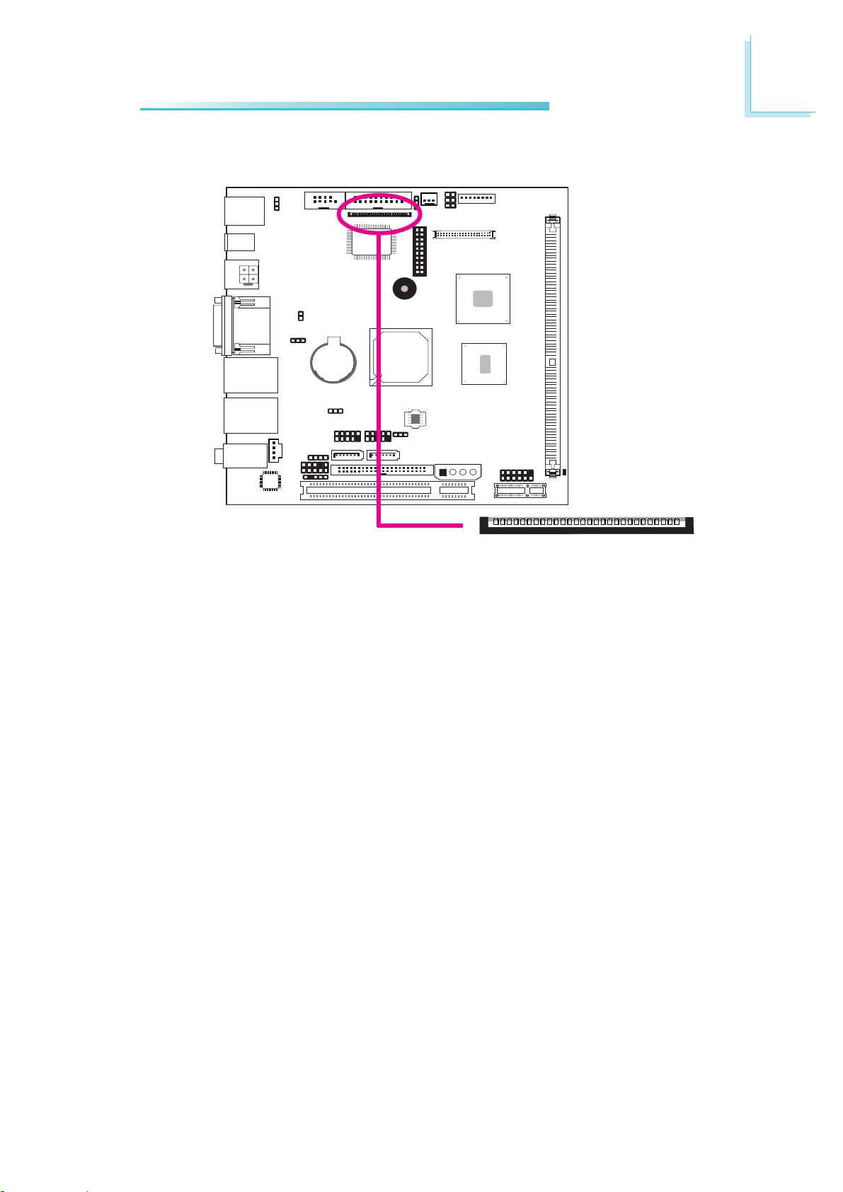
Floppy Disk Drive (FDD) Connector
Hardware Installation
2
X
The system board is equipped with a 26-pin FPC type floppy disk
drive connector. Only connect a 1.44MB slim-type floppy disk drive.
Refer to the next page for the pin function of this connector.
Connecting the Floppy Disk Drive Cable
Install one end of the floppy disk drive cable into the floppy disk
connector on the system board and the other end of the connector
to the floppy drive. Pin 1 of the cable must align with pin 1 of the
FDD connector.
BIOS Setting
Enable or disable this function in the Integrated Peripherals submenu
(“Super IO Device” section) of the BIOS. Refer to chapter 3 for
more information.
1
45
Page 46

2
Hardware Installation
FPC Type FDD Connector
Pins
1
3
5
7
9
11
13
15
17
19
21
23
25
Function
5V
5V
5V
N. C.
N. C.
N. C.
DRVDE0
GND
GND
GND
GND
GND
GND
Pins
2
4
6
8
10
12
14
16
18
20
22
24
26
Function
INDEX#
DR0#
DSKCH#
N. C.
MTR0#
DIR#
STEP#
WDATA#
WGATE#
TRK0#
WRPRO#
RDATA#
HDSEL#
46
Page 47
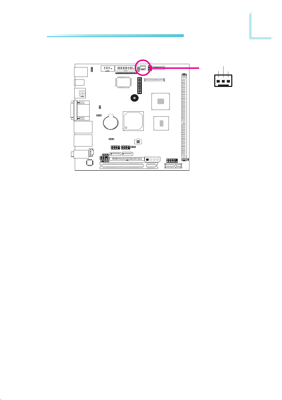
Cooling Fan Connector
Hardware Installation
Power
Ground
X
13
Sense
2
The fan connector is used to connect a cooling fan. The cooling fan
will provide adequate airflow throughout the chassis to prevent
overheating the CPU and system board components.
BIOS Setting
The PC Health Status submenu of the BIOS will display the current
speed of the cooling fan. Refer to chapter 3 for more information.
47
Page 48
2
Hardware Installation
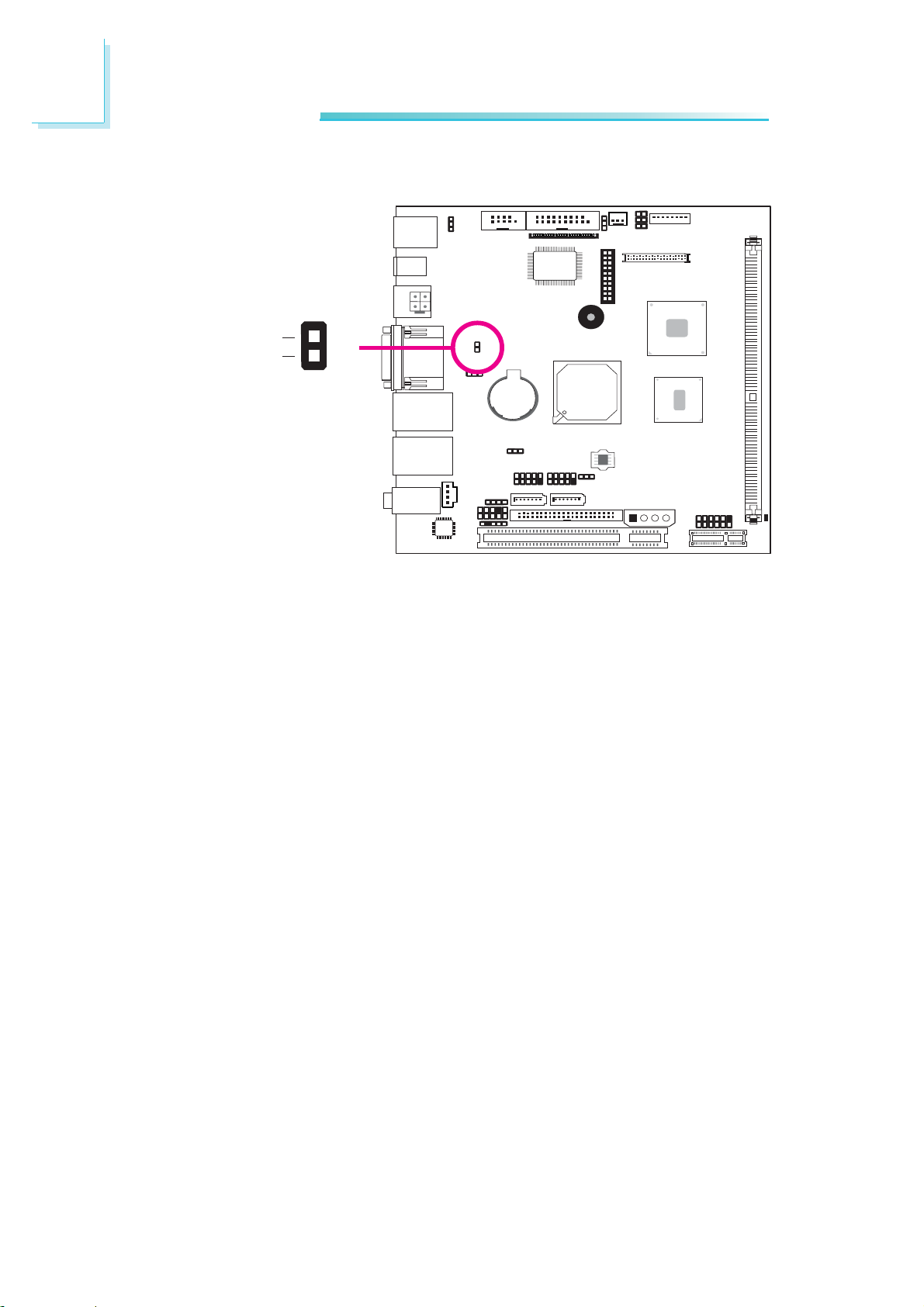
Chassis Instrusion Connector
Ground
Chassis signal
The board supports the chassis intrusion detection function. Connect
the chassis intrusion sensor cable from the chassis to this connector.
Regardless of whether the system’s power is on or not, as long as
the chassis cover has been opened, an alarm will sound once the
system restarts alerting you that a chassis intrusion event has
occurred. Reset this function in the BIOS.
Hardware Monitor for Windows
X
1
2
48
Install the “Hardware Monitor for Windows” utility. By default, the
chassis intrusion detection function is disabled. When enabled, a
warning message will appear when the chassis is open. The utility can
also be configured so that a beeping alarm will sound when the
chassis is open. Refer to the “Hardware Monitor for Windows” section in chapter 4 for more information.
Page 49
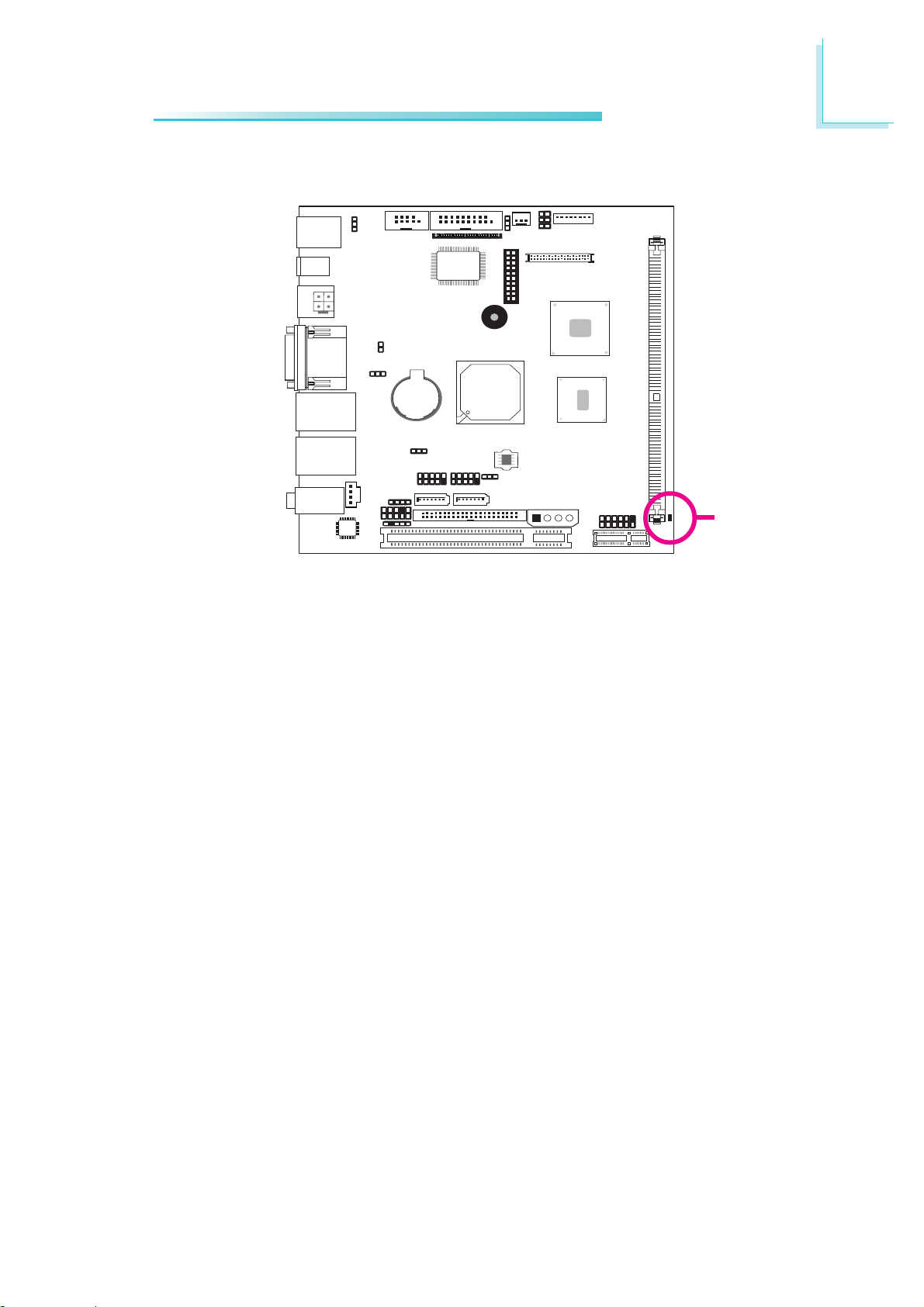
Standby LED
Hardware Installation
2
Standby
LED
This LED will lit red when the system is in the standby mode. It
indicates that there is power on the system board. Power-off the PC
then unplug the power cord prior to installing any devices. Failure to
do so will cause severe damage to the motherboard and
components.
49
Page 50
2
Hardware Installation
Front Panel Connectors
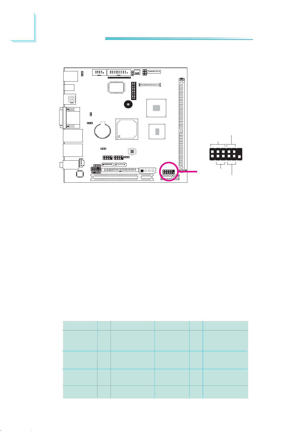
PWR-BTN
PWR-LED
2
1
HDD-LED
X
RESET SW
12
11
HDD-LED - HDD LED
This LED will light when the hard drive is being accessed.
RESET SW - Reset Switch
This switch allows you to reboot without having to power off the
system.
PWR-BTN - Power Switch
This switch is used to power on or off the system.
PWR-LED - Power/Standby LED
When the system’s power is on, this LED will light. When the system
is in the S1 (POS - Power On Suspend) state, it will blink every
second. When the system is in the S3 (STR - Suspend To RAM)
state, it will blink every 4 seconds.
50
N. C.
HDD-LED
RESET SW
N. C.
Pin
Pin Assignment
1
N. C.
3
HDD Power
5
Signal
7
Ground
9
RST Signal
11
N. C.
PWR-LED
PWR-BTN
Key
Pin Assignment
Pin
LED Power
2
LED Power
4
Signal
6
GND
8
Signal
10
Key
12
Page 51
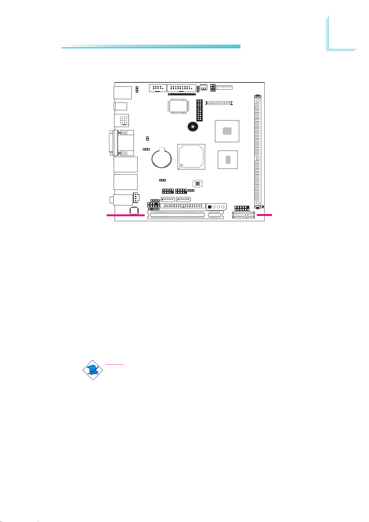
Expansion Slots
Hardware Installation
2
PCI
PCI Express x1
Install PCI Express cards such as network cards or other cards that
comply to the PCI Express specifications into the PCI Express x1
slot.
PCI Slot
The PCI slot supports expansion cards that comply with PCI
specifications. You can install a PCI expansion card or a customized
riser card designed for 1, 2 or 3 PCI slots expansion (for low
profile PCI card only) into the PCI slot.
Note:
You can install daughterboards on the PCI and PCI Express x1
slots. The supported daughterboards are:
PCI Express x1
• X100-2PE1 (one PCI slot and one PCI Express x1 slot)
• X100-2PC2 (two PCI slots)
• X100-2PC3 (three PCI slots)
These daughterboards, which comply with PCI specifications,
allow you to connect external PCI or PCI Express device.
51
Page 52
2
Hardware Installation
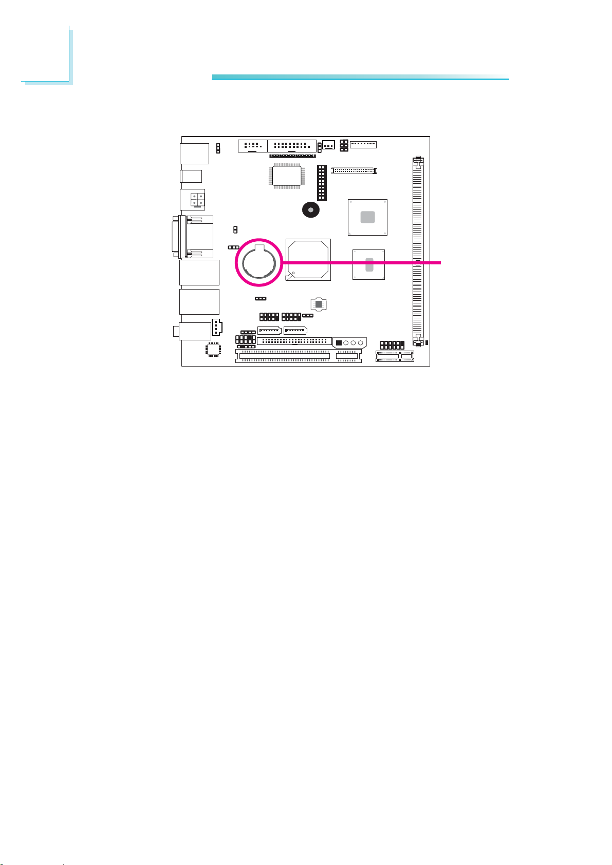
Battery
Battery
The lithium ion battery powers the real-time clock and CMOS
memory. It is an auxiliary source of power when the main power is
shut off.
Safety Measures
• Danger of explosion if battery incorrectly replaced.
• Replace only with the same or equivalent type recommend
the manufacturer.
• Dispose of used batteries according to local ordinance.
by
52
Page 53

Chapter 3 - BIOS Setup
Award BIOS Setup Utility
The Basic Input/Output System (BIOS) is a program that takes care
of the basic level of communication between the processor and peripherals. In addition, the BIOS also contains codes for various advanced features found in this system board. This chapter explains the
Setup Utility for the Award BIOS.
After you power up the system, the BIOS message appears on the
screen and the memory count begins. After the memory test, the
following message will appear on the screen:
Press DEL to enter setup
BIOS Setup
3
If the message disappears before you respond, restart the system or
press the “Reset” button. You may also restart the system by pressing the <Ctrl> <Alt> and <Del> keys simultaneously.
When you press <Del>, the main menu screen will appear.
Phoenix - AwardBIOS CMOS Setup Utility
X Standard CMOS Features
X Advanced BIOS Features
X Advanced Chipset Features
X Integrated Peripherals
X Power Management Setup
X PnP/PCI Configurations
X PC Health Status
Esc : Quit
F10 : Save & Exit Setup
Time, Date, Hard Disk Type...
Load Fail-Safe Defaults
Load Optimized Defaults
Set Supervisor Password
Set User Password
Save & Exit Setup
Exit Without Saving
↑ ↓ → ← : Select Item
53
Page 54

3
BIOS Setup
Standard CMOS Features
Use the arrow keys to highlight “Standard CMOS Features” and
press <Enter>. A screen similar to the one below will appear.
Date
Phoenix - AwardBIOS CMOS Setup Utility
Date <mm:dd:yy>
Time <hh:mm:ss>
X IDE Channel 0 Master
X IDE Channel 0 Slave
X IDE Channel 1 Master
X IDE Channel 1 Slave
Video
Halt On
Base Memory
Extended Memory
Total Memory
↑↓→←: Move Enter: Select F1: General Help+/-/PU/PD: Value F10: Save ESC: Exit
F5: Previous Values F6: Fail-Safe Defaults F7: Optimized Defaults
Standard CMOS Features
Tue, Dec 16 2008
9 : 3 : 54
None
None
None
None
EGA/VGA
All Errors
640K
1038336K
1039360K
Item Help
Menu Level
Change the day, month,
year and century
X
The settings on the screen are for reference only. Your version may not be
identical to this one.
The date format is <day>, <month>, <date>, <year>. Day displays
a day, from Sunday to Saturday. Month displays the month, from
January to December. Date displays the date, from 1 to 31. Year
displays the year, from 1999 to 2099.
54
Time
The time format is <hour>, <minute>, <second>. The time is based
on the 24-hour military-time clock. For example, 1 p.m. is 13:00:00.
Hour displays hours from 00 to 23. Minute displays minutes from
00 to 59. Second displays seconds from 00 to 59.
Page 55

IDE Channel 0 Master to IDE Channel 1 Slave
To configure the IDE drives, move the cursor to a field then press
<Enter>. The following screen will appear.
BIOS Setup
3
Phoenix - AwardBIOS CMOS Setup Utility
IDE HDD Auto-Detection
IDE Channel 0 Master
Access Mode
Capacity
Cylinder
Head
Precomp
Landing Zone
Sector
↑↓→←: Move Enter: Select F1: General Help+/-/PU/PD: Value F10: Save ESC: Exit
F5: Previous Values F6: Fail-Safe Defaults F7: Optimized Defaults
IDE Channel 0 Master
Press Enter
Auto
Auto
0MB
0
0
0
0
0
Item Help
Menu Level
To auto-detect the
HDD’s size, head... on
this channel
XX
The settings on the screen are for reference only. Your version may not be
identical to this one.
IDE HDD Auto Detection
Detects the parameters of the drive. The parameters will automatically be shown on the screen.
IDE Channel 0 Master to IDE Channel 1 Slave
If you select ”Auto”, the BIOS will auto-detect the HDD & CDROM drive at the POST stage and show the IDE for the HDD &
CD-ROM drive. If a hard disk has not been installed, select “None”.
Access Mode
For hard drives larger than 528MB, you would typically select the
LBA type. Certain operating systems require that you select CHS or
Large. Please check your operating system’s manual or Help desk on
which one to select.
55
Page 56

3
BIOS Setup
Capacity
Displays the approximate capacity of the disk drive. Usually the size
is slightly greater than the size of a formatted disk given by a disk
checking program.
Cylinder
This field displays the number of cylinders.
Head
This field displays the number of read/write heads.
Precomp
This field displays the number of cylinders at which to change the
write timing.
Landing Zone
This field displays the number of cylinders specified as the landing
zone for the read/write heads.
Sector
This field displays the number sectors per track.
56
Page 57

Video
BIOS Setup
3
This field selects the type of video adapter used for the primary
system monitor. Although secondary monitors are supported, you do
not have to select the type. The default setting is EGA/VGA.
EGA/VGA Enhanced Graphics Adapter/Video Graphics Array. For
EGA, VGA, SVGA and PGA monitor adapters.
CGA 40 Color Graphics Adapter. Power up in 40-column
mode.
CGA 80 Color Graphics Adapter. Power up in 80-column
mode.
Mono Monochrome adapter. Includes high resolution mono-
chrome adapters.
Halt On
This field determines whether the system will stop if an error is
detected during power up. The default setting is All Errors.
No Errors The system boot will not stop for any errors detected.
All Errors The system boot will stop whenever the BIOS detects
All, But Keyboard The system boot will not stop for a keyboard
All, But Diskette The system boot will not stop for a disk error;
All, But Disk/Key The system boot will not stop for a disk or
Base Memory
Displays the amount of base (or conventional) memory installed in
the system. The value of the base memory is typically 512K for
systems with 512K memory installed on the motherboard or 640K
for systems with 640K or more memory installed on the
motherboard.
a non-fatal error.
error; it will stop for all other errors.
it will stop for all other errors.
keyboard error; it will stop for all other errors.
57
Page 58

3
BIOS Setup
Extended Memory
Displays the amount of extended memory detected during boot-up.
Total Memory
Displays the total memory available in the system.
58
Page 59

Advanced BIOS Features
The Advanced BIOS Features allows you to configure your system
for basic operation. Some entries are defaults required by the system
board, while others, if enabled, will improve the performance of your
system or let you set some features according to your preference.
Phoenix - AwardBIOS CMOS Setup Utility
X CPU Feature
X Hard Disk Boot Priority
Virus Warning
CPU L1 & L2 Cache
Hyper-Threading Technology
Quick Powe-on Self Test
First Boot Device
Second Boot Device
Third Boot Device
Boot Other Device
Boot Up Floppy Seek
Boot Up NumLock Status
Gate A20 Option
Typematic Rate Setting
x Typematic Rate (Chars/Sec)
x Typematic Delay (Msec)
Security Option
x APIC Mode
MPS Version Control For OS
OS Select For DRAM > 64MB
Small Logo(EPA) Show
Advanced BIOS Features
Press Enter
Press Enter
Disabled
Enabled
Enabled
Enabled
Hard Disk
CDROM
LAN
Enabled
Enabled
On
Fast
Disabled
6
250
Setup
Enabled
1.4
Non-OS2
Disabled
X
Menu Level
Select Removable Boot
Device Priority
X
Item Help
BIOS Setup
3
X
↑↓→←: Move Enter: Select F1: General Help+/-/PU/PD: Value F10: Save ESC: Exit
F5: Previous Values F6: Fail-Safe Defaults F7: Optimized Defaults
The screen above list all the fields available in the Advanced BIOS Features
submenu, for ease of reference in this manual. In the actual CMOS setup, you have
to use the scroll bar to view the fields. The settings on the screen are for reference
only. Your version may not be identical to this one.
59
Page 60

3
BIOS Setup
CPU Feature
This field is used to configure the CPU that is installed on the system board. Move the cursor to this field then press <Enter>.
Phoenix - AwardBIOS CMOS Setup Utility
Delay Prior to Thermal
Limit CPUID MaxVal
C1E Function
Execute Disable Bit
↑↓: Move PU/PD/+/-: Change Priority F10: Save ESC: Exit
F5: Previous Values F6: Fail-Safe Defaults F7: Optimized Defaults
The settings on the screen are for reference only. Your version may not be
identical to this one.
CPU Feature
16 Min
Disabled
Auto
Enabled
Item Help
Menu Level
XX
Delay Prior To Thermal
This field is used to select the time that would force the CPU to a
50% duty cycle when it exceeds its maximum operating temperature
therefore protecting the CPU and the system board from overheating to ensure a safe computing environment..
60
Limit CPUID MaxVal
The CPUID instruction of some newer CPUs will return a value
greater than 3. The default is Disabled because this problem does
not exist in the Windows series operating systems. If you are using
an operating system other than Windows, this problem may occur. To
avoid this problem, enable this field to limit the return value to 3 or
lesser than 3.
C1E Function
The options are Auto and Disabled.
Execute Disable Bit
When this field is set to Disabled, it will force the XD feature flag to
always return to 0.
Page 61

Hard Disk Boot Priority
This field is used to select the boot sequence of the hard drives.
Move the cursor to this field then press <Enter>. Use the Up or
Down arrow keys to select a device then press <+> to move it up
or <-> to move it down the list.
BIOS Setup
3
1. Bootable Add-in Cards
↑↓: Move PU/PD/+/-: Change Priority F10: Save ESC: Exit
F5: Previous Values F6: Fail-Safe Defaults F7: Optimized Defaults
The settings on the screen are for reference only. Your version may not be
identical to this one.
Virus Warning
This field protects the boot sector and partition table of your hard
disk drive. When this field is enabled, the Award BIOS will monitor
the boot sector and partition table of the hard disk drive. If an
attempt is made to write to the boot sector or partition table of
the hard disk drive, the BIOS will halt the system and an error
message will appear.
Phoenix - AwardBIOS CMOS Setup Utility
Hard Disk Boot Priority
Item Help
Menu Level
Use <↑> or <↓> to
select a device, then
press <+> to move it up,
or <-> to move it down
the list. Press <ESC> to
exit this menu.
XX
After seeing the error message, if necessary, you will be able to run
an anti-virus program to locate and remove the problem before any
damage is done. Many disk diagnostic programs which attempt to
access the boot sector table will cause the warning message to
appear. If you are running such a program, we recommend that you
first disable this field.
61
Page 62

3
BIOS Setup
CPU L1 and L2 Cache
This field is used to speed up the memory access. Enable the external cache for better performance.
Hyper-Threading Technology
This field is used to enable the functionality of an Intel® processor
that supports Hyper-Threading Technology and will appear only when
using this processor.
Quick Power On Self Test
This field speeds up Power On Self Test (POST) after you power on
the system. When Enabled, the BIOS will shorten or skip some check
items during POST.
First Boot Device, Second Boot Device, Third Boot Device and Boot
Other Device
Select the drive to boot first, second and third in the “First Boot
Device” “Second Boot Device” and “Third Boot Device” fields respectively. The BIOS will boot the operating system according to the
sequence of the drive selected. Set “Boot Other Device” to Enabled
if you wish to boot from another device.
Boot Up Floppy Seek
When enabled, the BIOS will check whether the floppy disk drive installed is 40 or 80 tracks. Note that the BIOS cannot distinguish between 720K, 1.2M, 1.44M and 2.88M drive types as they are all 80
tracks. When disabled, the BIOS will not search for the type of floppy
disk drive by track number. Note that there will not be any warning
message if the drive installed is 360KB.
Boot Up NumLock Status
62
This allows you to determine the default state of the numeric
keypad. By default, the system boots up with NumLock on wherein
the function of the numeric keypad is the number keys. When set to
Off, the function of the numeric keypad is the arrow keys.
Page 63

Gate A20 Option
This entry allows you to select how gate A20 is handled. Gate A20
is a device used to address memory above 1 Mbyte. Initially, gate A20
was handled via the keyboard controller. Today, while keyboards still
provide this support, it is more common, and much faster, for the system chipset to provide support for gate A20.
Typematic Rate Setting
Disabled Continually holding down a key on your keyboard will
cause the BIOS to report that the key is down.
Enabled The BIOS will not only report that the key is down,
but will first wait for a moment, and, if the key is still
down, it will begin to repor t that the key has been
depressed repeatedly. For example, you would use such
a feature to accelerate cursor movements with the arrow keys. You can then select the typematic rate and
typematic delay in the “Typematic Rate (Chars/Sec)”
and “Typematic Delay (Msec)” fields below.
BIOS Setup
3
Typematic Rate (Chars/Sec)
This field allows you to select the rate at which the keys are accelerated.
Typematic Delay (Msec)
This field allows you to select the delay between when the key was
first depressed and when the acceleration begins.
Security Option
This field determines when the system will prompt for the password
- everytime the system boots or only when you enter the BIOS
setup. Set the password in the Set Supervisor/User Password
submenu.
System The system will not boot and access to Setup will be
denied unless the correct password is entered at the
prompt.
Setup The system will boot, but access to Setup will be denied
unless the correct password is entered at the prompt.
63
Page 64

3
BIOS Setup
APIC Mode
Leave this field in its default setting.
MPS Version Control for OS
This field is used to select the MPS version used by the system.
OS Select for DRAM > 64MB
This field allows you to access the memory that is over 64MB in
OS/2. The options are: Non-OS2 and OS2.
Small Logo(EPA) Show
Enabled The EPA logo will appear during system boot-up.
Disabled The EPA logo will not appear during system boot-up.
64
Page 65

Advanced Chipset Features
Phoenix - AwardBIOS CMOS Setup Utility
Advanced Chipset Features
DRAM Timing Selectable
x CAS Latency Time
x DRAM RAS# to CAS# Delay
x DRAM RAS# Precharge
x Precharge Delay <tRAS>
x System Memory Frequency
SLP_S4# Assertion Width
System BIOS Cacheable
Video BIOS Cacheable
Memory Hole At 15M-16M
X PCI Express Root Port Func
** VGA Setting **
On-Chip Frame Buffer Size
DVMT Mode
DVMT/FIXED Memory Size
Boot Display
Panel Scaling
Panel Number
By SPD
Auto
Auto
Auto
Auto
Auto
4 to 5 Sec.
Enabled
Disabled
Disabled
Press Enter
8MB
DVMT
128MB
Auto
Auto
3 : 1024*768 (18 bit)
Item Help
Menu Level
BIOS Setup
3
XX
↑↓→←: Move Enter: Select F1: General Help+/-/PU/PD: Value F10: Save ESC: Exit
F5: Previous Values F6: Fail-Safe Defaults F7: Optimized Defaults
The settings on the screen are for reference only. Your version may not be
identical to this one.
This section gives you functions to configure the system based on
the specific features of the chipset. The chipset manages bus speeds
and access to system memory resources. These items should not
be altered unless necessary. The default settings have been chosen
because they provide the best operating conditions for your system.
The only time you might consider making any changes would be if
you discovered some incompatibility or that data was being lost
while using your system.
DRAM Timing Selectable
This field is used to select the timing of the DRAM.
By SPD The EEPROM on a DIMM has SPD (Serial Pres-
ence Detect) data structure that stores information about the module such as the memory type,
memory size, memory speed, etc. When this option is selected, the system will run according to
the information in the EEPROM. This option is the
default setting because it provides the most stable condition for the system. The “CAS Latency
65
Page 66

3
BIOS Setup
Time” to “System Memory Frequency” fields will
show the default settings by SPD.
Manual If you want better performance for your system
other than the one “by SPD”, select “Manual” then
select the best option in the “CAS Latency Time”
to “System Memor y Frequency” fields.
CAS Latency Time
This field is used to select the local memory clock periods.
DRAM RAS# to CAS# Delay
This field is used to select the latency between the DRAM active
command and the read/write command.
DRAM RAS# Precharge
This field is used to select the idle clocks after issuing a precharge
command to the DRAM.
Precharge Delay (tRAS)
The options are Auto and 4 to15.
System Memory Frequency
This field is used to select the frequency of the system memory.
SLP_S4# Assertion Width
The options are 1 to 2 Sec., 2 to 3 Sec., 3 to 4 Sec. and 4 to 5
Sec.
System BIOS Cacheable
When this field is enabled, accesses to the system BIOS ROM addressed at F0000H-FFFFFH are cached, provided that the cache
controller is enabled. The larger the range of the Cache RAM, the
higher the efficiency of the system.
66
Page 67

Video BIOS Cacheable
As with caching the system BIOS, enabling the Video BIOS cache will
allow access to video BIOS addresssed at C0000H to C7FFFH to
be cached, if the cache controller is also enabled. The larger the range
of the Cache RAM, the faster the video performance.
Memory Hole At 15M-16M
In order to improve system performance, certain space in memory can
be reserved for ISA cards. This memory must be mapped into the
memory space below 16MB. When enabled, the CPU assumes the 1516MB memory range is allocated to the hidden ISA address range
instead of the actual system DRAM. When disabled, the CPU assumes
the 15-16MB address range actually contains DRAM memory. If more
than 16MB of system memory is installed, this field must be disabled
to provide contiguous system memory.
BIOS Setup
3
PCI Express Root Port Func
Phoenix - AwardBIOS CMOS Setup Utility
PCI Express Port 1
PCI-E Compliancy Mode
↑↓→←: Move Enter: Select F1: General Help+/-/PU/PD: Value F10: Save ESC: Exit
F5: Previous Values F6: Fail-Safe Defaults F7: Optimized Defaults
The settings on the screen are for reference only. Your version may not be
identical to this one.
PCI Express Port 1
This field is used to enable or disable the PCI Express port function.
PCI Express Root Port Func
Auto
v1.0a
Item Help
Menu Level
XX
PCI-E Compliancy Mode
This field is used to select the mode for the PCI Express add-in
card.
67
Page 68

3
BIOS Setup
On-Chip Frame Buffer Size
This field is used to select the onboard VGA’s frame buffer size that
is shared from the system memory.
DVMT Mode
The options are DVMT, Fixed and Both.
DVMT/Fixed Memory Size
This field is used to select the graphics memory size used by DVMT/
Fixed mode.
Boot Display
This field is used to select the type of display to use when the
system boots.
CRT Select this option if you want the system to boot
LVDS Select this option if you want the system to boot
CRT+LVDS Select this option if you want the system to boot
DVI Select this option if you want the system to boot
CR T+DVI Select this option if you want the system to boot
Panel Scaling
This options are Auto, On and Off.
Panel Number
This field is used to select the type of panel that you are using.
the CRT display.
the LCD flat panel display.
both the CRT and LCD flat panel display.
the NP1-DVI daughterboard’s DVI-D’s display.
both the CRT and NP1-DVI daughterboard’s DVI-
D’s display.
68
Page 69
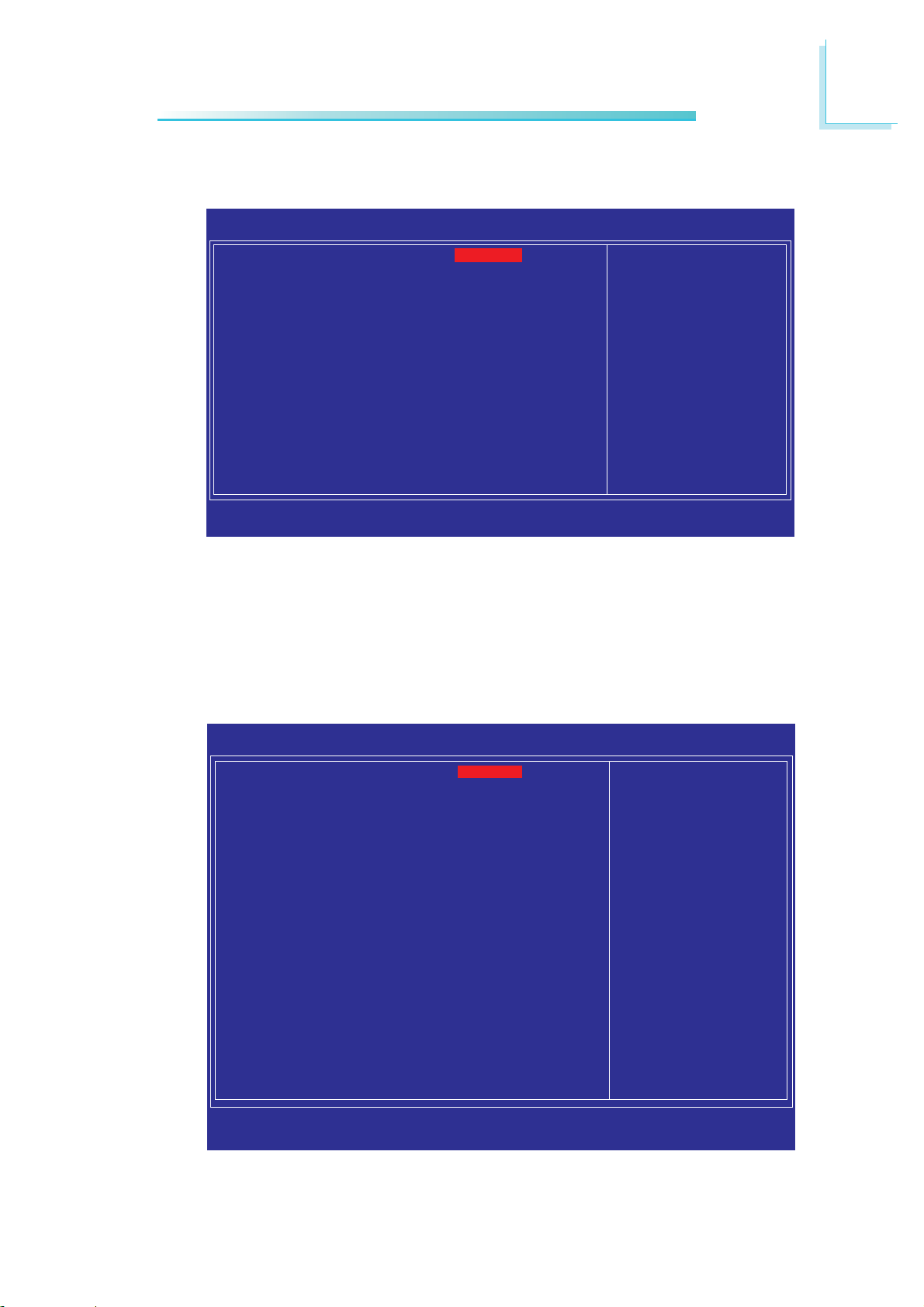
Integrated Peripherals
BIOS Setup
3
X OnChip IDE Device
X Onboard Device
X Super IO Device
↑↓→←: Move Enter: Select F1: General Help+/-/PU/PD: Value F10: Save ESC: Exit
F5: Previous Values F6: Fail-Safe Defaults F7: Optimized Defaults
The settings on the screen are for reference only. Your version may not be
identical to this one.
OnChip IDE Device
Move the cursor to this field and press <Enter>. The following
screen will appear.
Phoenix - AwardBIOS CMOS Setup Utility
Integrated Peripherals
Press Enter
Press Enter
Press Enter
Item Help
Menu Level
X
Phoenix - AwardBIOS CMOS Setup Utility
IDE HDD Block Mode
IDE DMA Transfer Access
On-Chip Primary PCI IDE
IDE Primary Master UDMA
IDE Primary Slave UDMA
On-Chip Serial ATA Setting
***
x SATA Mode
On-Chip Serial ATA
x PATA IDE Mode
SATA Port
↑↓→←: Move Enter: Select F1: General Help+/-/PU/PD: Value F10: Save ESC: Exit
F5: Previous Values F6: Fail-Safe Defaults F7: Optimized Defaults
OnChip IDE Device
Enabled
Enabled
Enabled
Auto
Auto
***
IDE
Auto
Secondary
P0, P2 is Primary
Item Help
Menu Level
If your IDE hard drive
supports block mode
Select Enabled for
automatic detection of
the optimal number of
block read/writes per
sector the drive can
support
X
The settings on the screen are for reference only. Your version may not be
identical to this one.
69
Page 70

3
BIOS Setup
IDE HDD Block Mode
Enabled The IDE HDD uses the block mode. The system BIOS
will check the hard disk drive for the maximum block
size the system can transfer. The block size will depend
on the type of hard disk drive.
Disabled The IDE HDD uses the standard mode.
IDE DMA Transfer Access
This field is used to enable or disable the DMA transfer function of
an IDE hard drive.
On-Chip Primary PCI IDE
This field allows you to enable or disable the primary and secondary
IDE controller. The default is Enabled. Select Disabled if you want to
add a different hard drive controller
IDE Primary Master/Slave UDMA
These fields allow you to set the Ultra DMA in use. When Auto is
selected, the BIOS will select the best available option after checking
your hard drive or CD-ROM
Auto The BIOS will automatically detect the settings for
you.
Disabled The BIOS will not detect these categories.
SATA Mode
IDE This option configures the Serial ATA drives as
Parallel ATA storage devices.
AHCI This option allows the Serial ATA devices to use
AHCI (Advanced Host Controller Interface).
70
Page 71

BIOS Setup
On-Chip Serial ATA
Disabled Disables the onboard SATA.
Auto The system will detect the existing SATA and
IDE drives then automatically set them to the
available master/slave mode.
Combined Mode This option allows you to combine both IDE
and SATA drives; supporting maximum of 2
drives on each channel.
Enhanced Mode This option allows you to use both IDE and
SATA drives; allowing a maximum of 4 drives 1 IDE Master, 1 IDE Slave and 2 SATA.
SATA Only This option automatically sets the SATA drives
to Primary Master mode. Since the SATA
drives are in Master mode, you cannot set the
IDE drive to Master mode.
3
PATA IDE Mode and SATA Port
This field is used to select the function mode for the IDE connector
and its relation to the SATA ports.
Primary IDE serves as Primary Master and Primary
Slave channel. SATA 1 and SATA 2 serve as
Secondary Master and Secondary Slave channel.
Secondary IDE serves as Secondary Master and Second-
ary Slave channel. SATA 1 and SATA 2 serve
as Primary Master and Primary Slave channel.
71
Page 72

3
BIOS Setup
Onboard Device
Move the cursor to this field and press <Enter>. The following
screen will appear.
Phoenix - AwardBIOS CMOS Setup Utility
Onboard LAN1 Control
Onboard LAN2 Control
Onboard PXE ROM Control
Azalia/AC97 Audio Select
X USB Device Setting
↑↓→←: Move Enter: Select F1: General Help+/-/PU/PD: Value F10: Save ESC: Exit
F5: Previous Values F6: Fail-Safe Defaults F7: Optimized Defaults
The settings on the screen are for reference only. Your version may not be
identical to this one.
Onboard Device
Enabled
Enabled
Disabled
Auto
Press Enter
Item Help
Menu Level
XX
Onboard LAN1 Control and Onboard LAN2 Control
These fields are used to enable or disable the onboard LAN
controllers.
Onboard PXE ROM Control
Enable this field if you wish to use the boot ROM (instead of a disk
drive) to boot-up the system and access the local area network
directly. If you wish to change the boot ROM’s settings, type the
<Shift> and <F10> keys simultaneously when prompted during
boot-up. Take note: you will be able to access the boot ROM’s
program (by typing <Shift> + <F10>) only when this field is
enabled.
Azalia/AC97 Audio Select
Auto Enables the onboard Azalia/AC97 CODEC.
Disabled Disables the onboard audio. Disable the onboard
audio when using an audio PCI card.
72
Page 73

BIOS Setup
USB Device Setting
Move the cursor to this field and press <Enter>. The following
screen will appear.
3
Phoenix - AwardBIOS CMOS Setup Utility
USB 1.0 Controller
USB 2.0 Controller
USB Operation Mode
USB Keyboard Function
USB Mouse Function
USB Storage Function
*** USB Mass Storage Device Boot Setting ***
MITSUMI
↑↓→←: Move Enter: Select F1: General Help+/-/PU/PD: Value F10: Save ESC: Exit
F5: Previous Values F6: Fail-Safe Defaults F7: Optimized Defaults
The settings on the screen are for reference only. Your version may not be
identical to this one.
USB Device Setting
Enabled
Enabled
High Speed
Enabled
Enabled
Enabled
USB Floppy
Item Help
Menu Level
XX
USB 1.0 Controller
This field is used to enable or disable the Universal Host Controller
Interface (USB 1.0).
USB 2.0 Controller
This field is used to enable or disable the Enhanced Host Controller
Interface (USB 2.0).
USB Operation Mode
This field is used to select the USB’s operation mode. The options
are Full/Low Speed and High Speed.
73
Page 74

3
BIOS Setup
USB Keyboard Function
Due to the limited space of the BIOS ROM, the support for legacy
USB keyboard (in DOS mode) is by default set to Disabled. With
more BIOS ROM space available, it will be able to support more
advanced features as well as provide compatibility to a wide variety
of peripheral devices.
If a PS/2 keyboard is not available and you need to use a USB
keyboard to install Windows (installation is performed in DOS
mode) or run any program under DOS, set this field to Enabled.
USB Mouse Function
Due to the limited space of the BIOS ROM, the support for legacy
USB mouse (in DOS mode) is by default set to Disabled. With
more BIOS ROM space available, it will be able to support more
advanced features as well as provide compatibility to a wide variety
of peripheral devices.
If a PS/2 mouse is not available and you need to use a USB mouse
to install Windows (installation is performed in DOS mode) or run
any program under DOS, set this field to Enabled.
USB Storage Function
This field is used to enable or disable the support for legacy USB
mass storage.
74
Page 75

Super IO Device
Move the cursor to this field and press <Enter>. The following
screen will appear.
BIOS Setup
3
Phoenix - AwardBIOS CMOS Setup Utility
Power On Function
x Hot Key Power ON
Onboard Serial Port 1
Onboard Serial Port 2
PWRON After PWR-Fail
W83627DHG.WDT Time
↑↓→←: Move Enter: Select F1: General Help+/-/PU/PD: Value F10: Save ESC: Exit
F5: Previous Values F6: Fail-Safe Defaults F7: Optimized Defaults
The settings on the screen are for reference only. Your version may not be
identical to this one.
Super IO Device
BUTTON ONLY
Ctrl-F1
3F8/IRQ4
2F8/IRQ3
Off
0
Item Help
Menu Level
XX
Power On Function
This field allows you to use the PS/2 keyboard or PS/2 mouse to
power-on the system.
Keyboard 98 When this option is selected, press the “wake up”
key of the Windows® 98 compatible keyboard to
power-on the system.
Button only Default setting. Uses the power button to power
on the system.
Hot Key When this option is selected, select the function
key you would like to use to power-on the system
in the “Hot Key Power On” field.
Mouse Left When this option is selected, double-click the left
button of the mouse to power-on the system.
Mouse Right When this option is selected, double-click the right
button of the mouse to power-on the system.
Any Key Press any key to power-on the system.
75
Page 76

3
BIOS Setup
Hot Key Power On
This field is used to select a function key that you would like to use
to power-on the system.
Onboard Serial Port 1 and Onboard Serial Port 2
3F8/IRQ4, 2F8/IRQ3, 3E8/IRQ4, 2E8/IRQ3 Allows you to
manually select an I/O address for the onboard serial port.
Disabled Disables the onboard serial port.
PWRON After PWR-Fail
Off When power returns after an AC power failure, the
system’s power is off. You must press the Power button
to power-on the system.
On When power returns after an AC power failure, the
system will automatically power-on.
Former-Sts When power returns after an AC power failure, the
system will return to the state where you left off before
power failure occurs. If the system’s power is off when
AC power failure occurs, it will remain off when power
returns. If the system’s power is on when AC power
failure occurs, the system will power-on when power
returns.
76
W83627DHG.WDT Time
This field is used to select the time interval of the Watchdog timer. If
the system hangs or fails to function, it will reset at the set time
interval so that your system will continue to operate.
Page 77

Power Management Setup
The Power Management Setup allows you to configure your system
to most effectively save energy.
Phoenix - AwardBIOS CMOS Setup Utility
ACPI Function
ACPI Suspend Type
Soft-Off By PWR-BTTN
Wake-Up by PCI Card
Wake-Up by Ring
USB KB Wake-Up From S3
Resume By Alarm
x Date(of Month) Alarm
x Time (hh:mm:ss) Alarm
Power Management Setup
Enabled
S3(STR)
Instant-Off
Disabled
Disabled
Disabled
Disabled
0
0 : 0 : 0
Item Help
Menu Level
BIOS Setup
3
X
↑↓→←: Move Enter: Select F1: General Help+/-/PU/PD: Value F10: Save ESC: Exit
F5: Previous Values F6: Fail-Safe Defaults F7: Optimized Defaults
The settings on the screen are for reference only. Your version may not be
identical to this one.
ACPI Function
This function should be enabled only in operating systems that
support ACPI.
ACPI Suspend Type
This field is used to select the type of Suspend mode.
S1(POS) Enables the Power On Suspend function.
S3(STR) Enables the Suspend to RAM function.
77
Page 78

3
BIOS Setup
Soft-Off by PWR-BTTN
This field allows you to select the method of powering off your
system.
Delay 4 Sec. Regardless of whether the Power Management func-
tion is enabled or disabled, if the power button is
pushed and released in less than 4 sec, the system
enters the Suspend mode. The purpose of this function is to prevent the system from powering off in
case you accidentally “hit” or pushed the power button. Push and release again in less than 4 sec to
restore. Pushing the power button for more than 4
seconds will power off the system.
Instant-Off Pressing and then releasing the power button at
once will immediately power off your system.
Wake-Up By PCI Card
Enabled This field should be set to Enabled only if your PCI
card such as LAN card or modem card uses the PCI
PME (Power Management Event) signal to remotely
wake up the system. Access to the LAN card or PCI
card will cause the system to wake up. Refer to the
card’s documentation for more information.
Disabled The system will not wake up despite access to the PCI
card.
Wake-Up By Ring
When this field is set to Enabled, the system will power-on to respond
to calls coming from a modem.
78
Page 79

USB KB Wake-Up From S3
This field, when enabled, allows you to use a USB keyboard or USB
mouse to wake up a system that is in the S3 (STR - Suspend To
RAM) state. This can be configured only if the “ACPI Suspend Type”
field is set to “S3(STR)”.
Resume By Alarm
Enabled When Enabled, you can set the date and time you
would like the Soft Power Down (Soft-Off) PC to
power-on in the “Date (of Month) Alarm” and “Time
(hh:mm:ss) Alarm” fields. However, if the system is being
accessed by incoming calls or the network (Resume On
Ring/LAN) prior to the date and time set in these
fields, the system will give priority to the incoming calls
or network.
Disabled Disables the automatic power-on function. (default)
BIOS Setup
3
Date (of Month) Alarm
0 The system will power-on everyday according to the
time set in the “Time (hh:mm:ss) Alarm” field.
1-31 Select a date you would like the system to power-on.
The system will power-on on the set date, and time set
in the “Time (hh:mm:ss) Alarm” field.
79
Page 80

3
BIOS Setup
Time (hh:mm:ss) Alarm
This is used to set the time you would like the system to power-on.
If you want the system to power-on everyday as set in the “Date
(of Month) Alarm” field, the time set in this field must be later than
the time of the RTC set in the Standard CMOS Features submenu.
80
Page 81

PnP/PCI Configurations
This section shows how to configure the PCI bus system. It covers
some very technical items and it is strongly recommended that only
experienced users should make any changes to the default settings.
BIOS Setup
3
Init Display First
Reset Configuration Data
Resources Controlled By
x IRQ Resources
PCI/VGA Palette Snoop
** PCI Express Relative Items **
Maximum Payload Size
↑↓→←: Move Enter: Select F1: General Help+/-/PU/PD: Value F10: Save ESC: Exit
F5: Previous Values F6: Fail-Safe Defaults F7: Optimized Defaults
The settings on the screen are for reference only. Your version may not be
identical to this one.
Init Display First
Onboard When the system boots, it will first initialize the
PCI Slot When the system boots, it will first initialize PCI.
Phoenix - AwardBIOS CMOS Setup Utility
PnP/PCI Configurations
onboard VGA.
Onboard
Disabled
Auto(ESCD)
Press Enter
Disabled
128
Item Help
Menu Level
X
Reset Configuration Data
Enabled The BIOS will reset the Extended System Configuration
Data (ESCD) once automatically. It will then recreate a
new set of configuration data.
Disabled The BIOS will not reset the configuration data.
81
Page 82
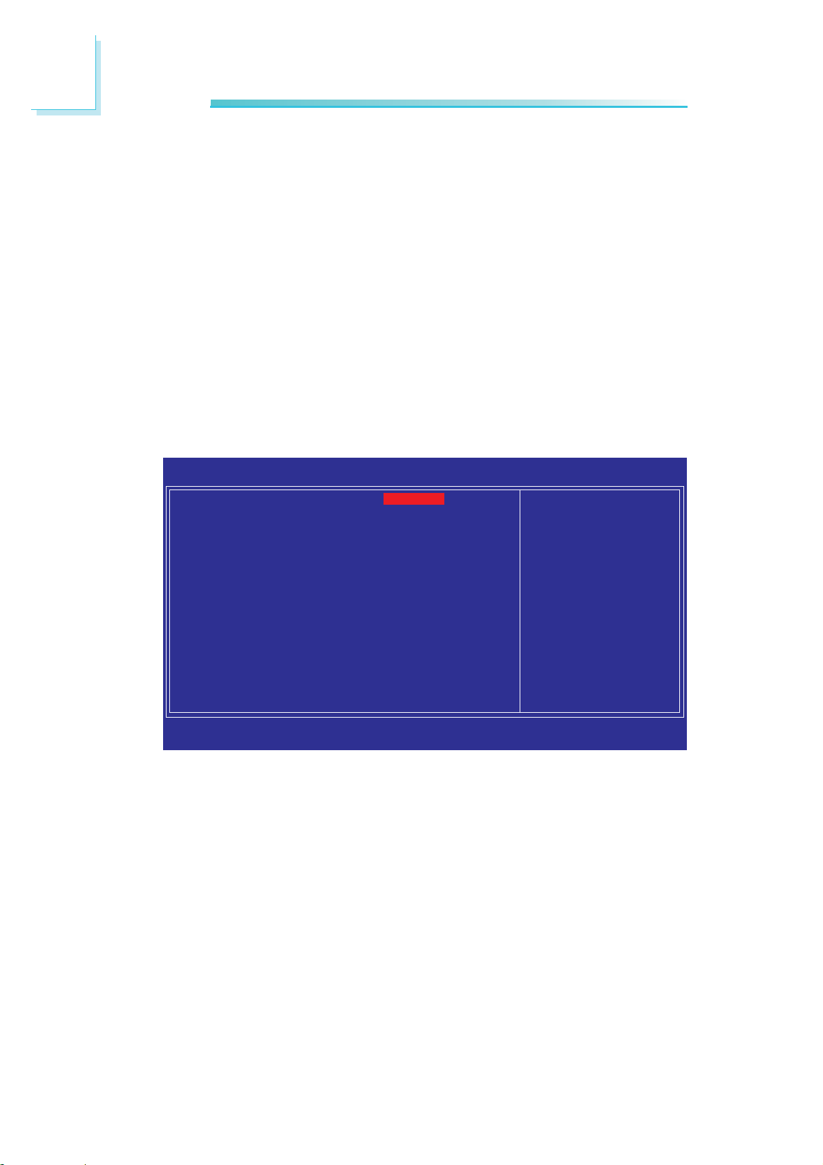
3
BIOS Setup
Resources Controlled By
The Award Plug and Play BIOS has the capability to automatically
configure all of the boot and Plug and Play compatible devices.
Auto(ESCD) The system will automatically detect the settings for
you.
Manual Choose the specific IRQ resources in the “IRQ Re-
sources” field.
IRQ Resources
Move the cursor to this field and press <Enter>. Set each system
interrupt to either PCI Device or Reserved.
IRQ- 3 assigned to
IRQ- 4 assigned to
IRQ- 5 assigned to
IRQ- 7 assigned to
IRQ- 9 assigned to
IRQ-10 assigned to
IRQ-11 assigned to
IRQ-12 assigned to
IRQ-14 assigned to
IRQ-15 assigned to
↑↓→←: Move Enter: Select F1: General Help+/-/PU/PD: Value F10: Save ESC: Exit
F5: Previous Values F6: Fail-Safe Defaults F7: Optimized Defaults
The settings on the screen are for reference only. Your version may not be
identical to this one.
PCI/VGA Palette Snoop
This field determines whether the MPEG ISA/VESA VGA cards can
work with PCI/VGA or not. The default value is Disabled.
Phoenix - AwardBIOS CMOS Setup Utility
IRQ Resources
PCI Device
PCI Device
PCI Device
PCI Device
PCI Device
PCI Device
PCI Device
PCI Device
PCI Device
PCI Device
Item Help
Menu Level
Legacy ISA for devices
compliant with the
original PC AT bus
specification. PCI/ISA
PnP for devices
compliant with the Plug
and Play standard
whether designed for
PCI or ISA bus
architecture.
XX
82
Enabled MPEG ISA/VESA VGA cards work with PCI/VGA.
Disabled MPEG ISA/VESA VGA cards does not work with PCI/
VGA.
Maximum Payload Size
This field is used to select the maximum TLP payload size of the PCI
Express devices. The unit is byte.
Page 83

PC Health Status
BIOS Setup
3
Phoenix - AwardBIOS CMOS Setup Utility
Case Open Warning
Shutdown Temperature
Current SYS Temperature
Current CPU Temperature
Current System Fan Speed
Vcore
5V
1.05V
1.8V
+12V
VBAT (V)
↑↓→←: Move Enter: Select F1: General Help+/-/PU/PD: Value F10: Save ESC: Exit
F5: Previous Values F6: Fail-Safe Defaults F7: Optimized Defaults
PC Health Status
Disabled
Disabled
43oC/109oF
42oC/107oF
0 RPM
0.91V
5.09V
1.07V
1.82V
12.14V
3.31V
Item Help
Menu Level
X
The settings on the screen are for reference only. Your version may not be
identical to this one.
Case Open Warning
Set this field to Enabled to allow the system to alert you of a chassis intrusion event.
Shutdown Temperature
You can prevent the system from overheating by selecting a temperature at which the system will shutdown. If the system detected
that its temperature exceeded the one set in this field, it will automatically shutdown. This function will work only if your operating
system supports the ACPI feature.
Disabled Default setting.
o
80
C/140oF If the CPU’s temperature is higher than 80oC/140oF,
90oC/149oF If the CPU’s temperature is higher than 90oC/149oF,
the system will automatically shutdown.
the system will automatically shutdown.
83
Page 84
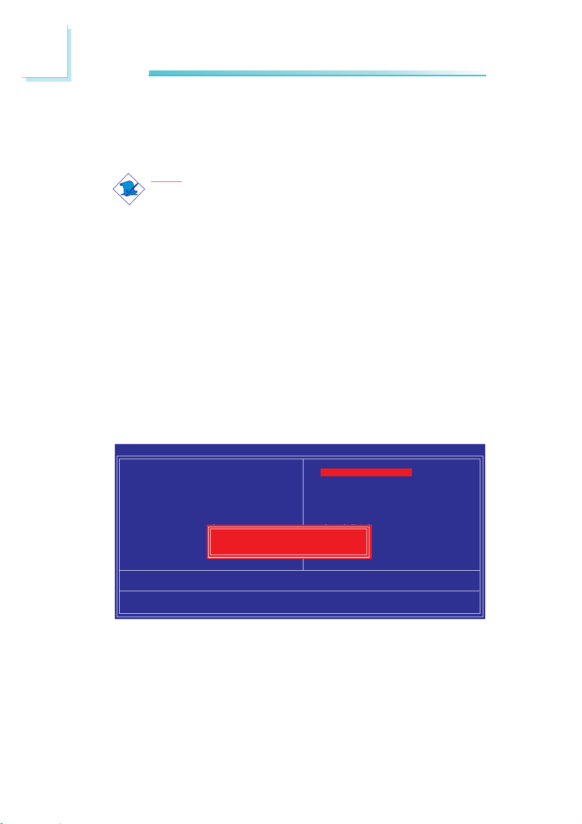
3
BIOS Setup
Current SYS Temperature to VBAT (V)
These fields will show the temperature, fan speed and output voltage
of the monitored devices or components.
Note:
The onboard hardware monitor function is capable of detecting
“system health” conditions but if you want a warning message
to pop-up or a warning alarm to sound when an abnormal
condition occurs, you must install the Hardware Monitor for
Windows utility. This utility is included in the CD that came with
the system board. Refer to the Hardware Monitor for Windows
section in chapter 4 for more information.
Load Fail-Safe Defaults
The “Load Fail-Safe Defaults” option loads the troubleshooting default values permanently stored in the ROM chips. These settings are
not optimal and turn off all high performance features. You should
use these values only if you have hardware problems. Highlight this
option in the main menu and press <Enter>.
Phoenix - AwardBIOS CMOS Setup Utility
X Standard CMOS Features
X Advanced BIOS Features
X Advanced Chipset Features
X Integrated Peripherals
X Power Management Setup
X PnP/PCI Configurations
X PC Health Status
Esc : Quit
F10 : Save & Exit Setup
Load Fail-Safe Defaults (Y/N)?
Load Fail-Safe Defaults
Load Fail-Safe Defaults
Load Optimized Defaults
Set Supervisor Password
Set User Password
Save & Exit Setup
Exit Without Saving
↑ ↓ → ← : Select Item
84
If you want to proceed, type <Y> and press <Enter>. The default
settings will be loaded.
Page 85
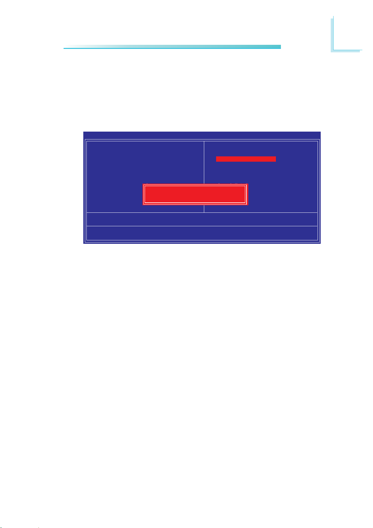
Load Optimized Defaults
The “Load Optimized Defaults” option loads optimized settings from
the BIOS ROM. Use the default values as standard values for your
system. Highlight this option in the main menu and press <Enter>.
Phoenix - AwardBIOS CMOS Setup Utility
BIOS Setup
3
X Standard CMOS Features
X Advanced BIOS Features
X Advanced Chipset Features
X Integrated Peripherals
X Power Management Setup
X PnP/PCI Configurations
X PC Health Status
Esc : Quit
F10 : Save & Exit Setup
Load Optimized Defaults (Y/N)?
Load Optimized Defaults
Load Fail-Safe Defaults
Load Optimized Defaults
Set Supervisor Password
Set User Password
Save & Exit Setup
Exit Without Saving
↑ ↓ → ← : Select Item
Type <Y> and press <Enter> to load the Setup default values.
85
Page 86
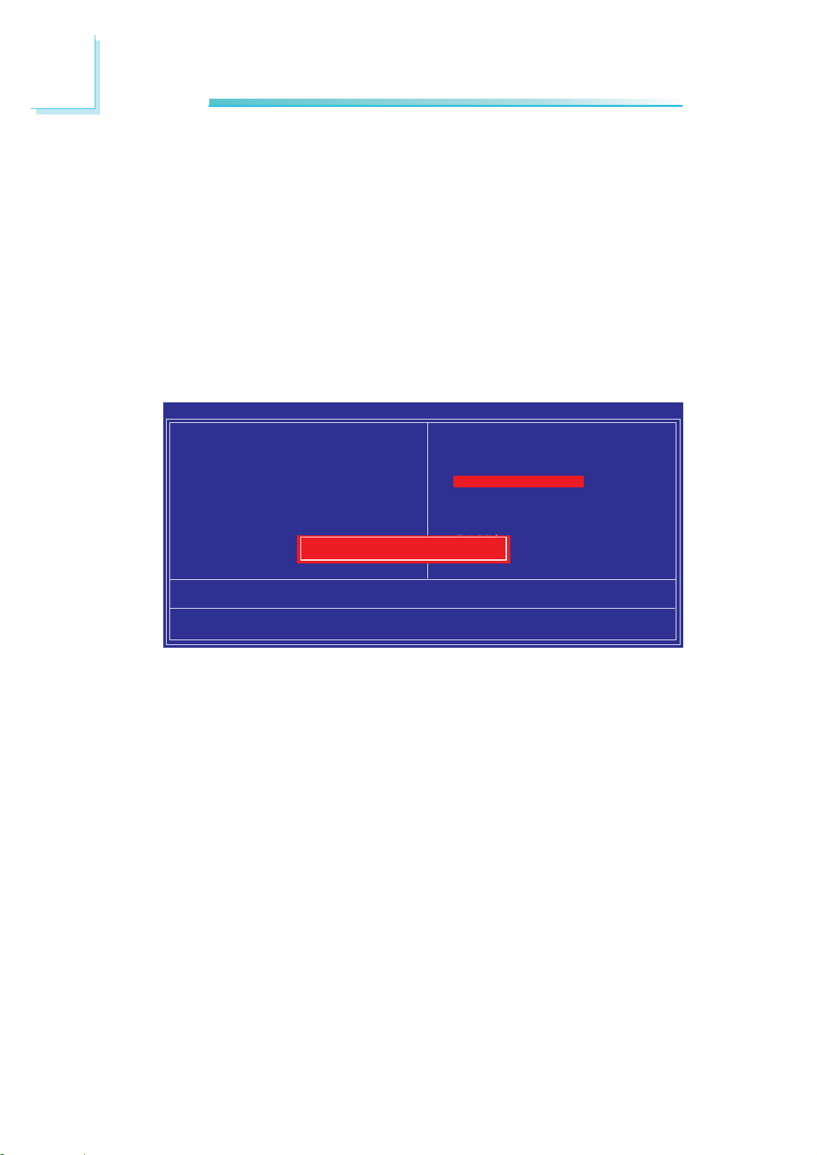
3
BIOS Setup
Set Supervisor Password
If you want to protect your system and setup from unauthorized
entry, set a supervisor’s password with the “System” option selected
in the Advanced BIOS Features. If you want to protect access to
setup only, but not your system, set a supervisor’s password with the
“Setup” option selected in the Advanced BIOS Features. You will not
be prompted for a password when you cold boot the system.
Use the arrow keys to highlight “Set Supervisor Password” and
press <Enter>.
Phoenix - AwardBIOS CMOS Setup Utility
X Standard CMOS Features
X Advanced BIOS Features
X Advanced Chipset Features
X Integrated Peripherals
X Power Management Setup
X PnP/PCI Configurations
X PC Health Status
Esc : Quit
F10 : Save & Exit Setup
Enter Password:
Change/Set/Disable Password
Load Fail-Safe Defaults
Load Optimized Defaults
Set Supervisor Password
Set User Password
Save & Exit Setup
Exit Without Saving
↑ ↓ → ← : Select Item
Type in the password. You are limited to eight characters. When
done, the message below will appear:
Confirm Password:
You are asked to verify the password. Type in exactly the same
password. If you type in a wrong password, you will be prompted
to enter the correct password again. To delete or disable the password function, highlight “Set Supervisor Password” and press <Enter>, instead of typing in a new password. Press the <Esc> key to
return to the main menu.
86
Page 87
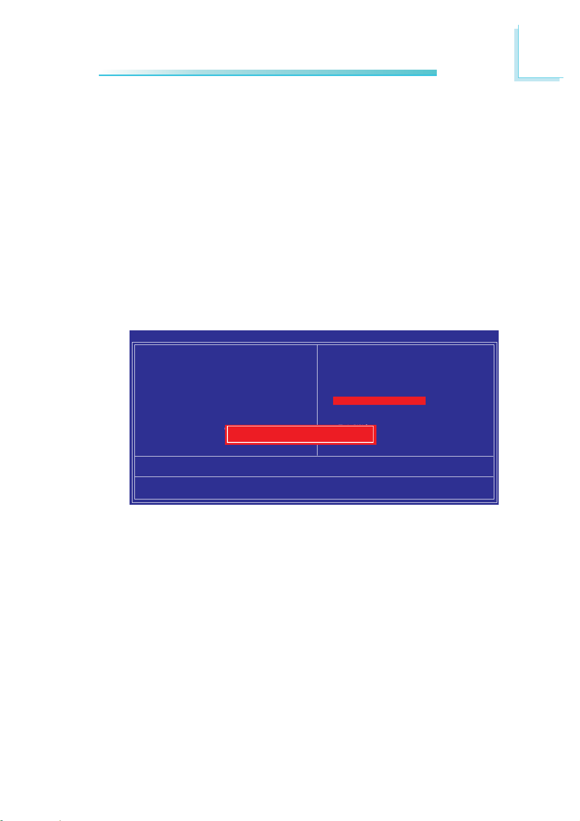
Set User Password
If you want another user to have access only to your system but
not to setup, set a user’s password with the “System” option selected in the Advanced BIOS Features. If you want a user to enter a
password when trying to access setup, set a user’s password with
the “Setup” option selected in the Advanced BIOS Features.
Using user’s password to enter Setup allows a user to access only
“Set User Password” that appears in the main menu screen. Access
to all other options is denied.
Use the arrow keys to highlight “Set User Password” and press
<Enter>.
BIOS Setup
3
Phoenix - AwardBIOS CMOS Setup Utility
X Standard CMOS Features
X Advanced BIOS Features
X Advanced Chipset Features
X Integrated Peripherals
X Power Management Setup
X PnP/PCI Configurations
X PC Health Status
Esc : Quit
F10 : Save & Exit Setup
Enter Password:
Change/Set/Disable Password
Load Fail-Safe Defaults
Load Optimized Defaults
Set Supervisor Password
Set User Password
Save & Exit Setup
Exit Without Saving
↑ ↓ → ← : Select Item
Type in the password. You are limited to eight characters. When
done, the message below will appear:
Confirm Password:
You are asked to verify the password. Type in exactly the same
password. If you type in a wrong password, you will be prompted
to enter the correct password again. To delete or disable the password function, highlight “Set User Password” and press <Enter>, instead of typing in a new password. Press the <Esc> key to return
to the main menu.
87
Page 88
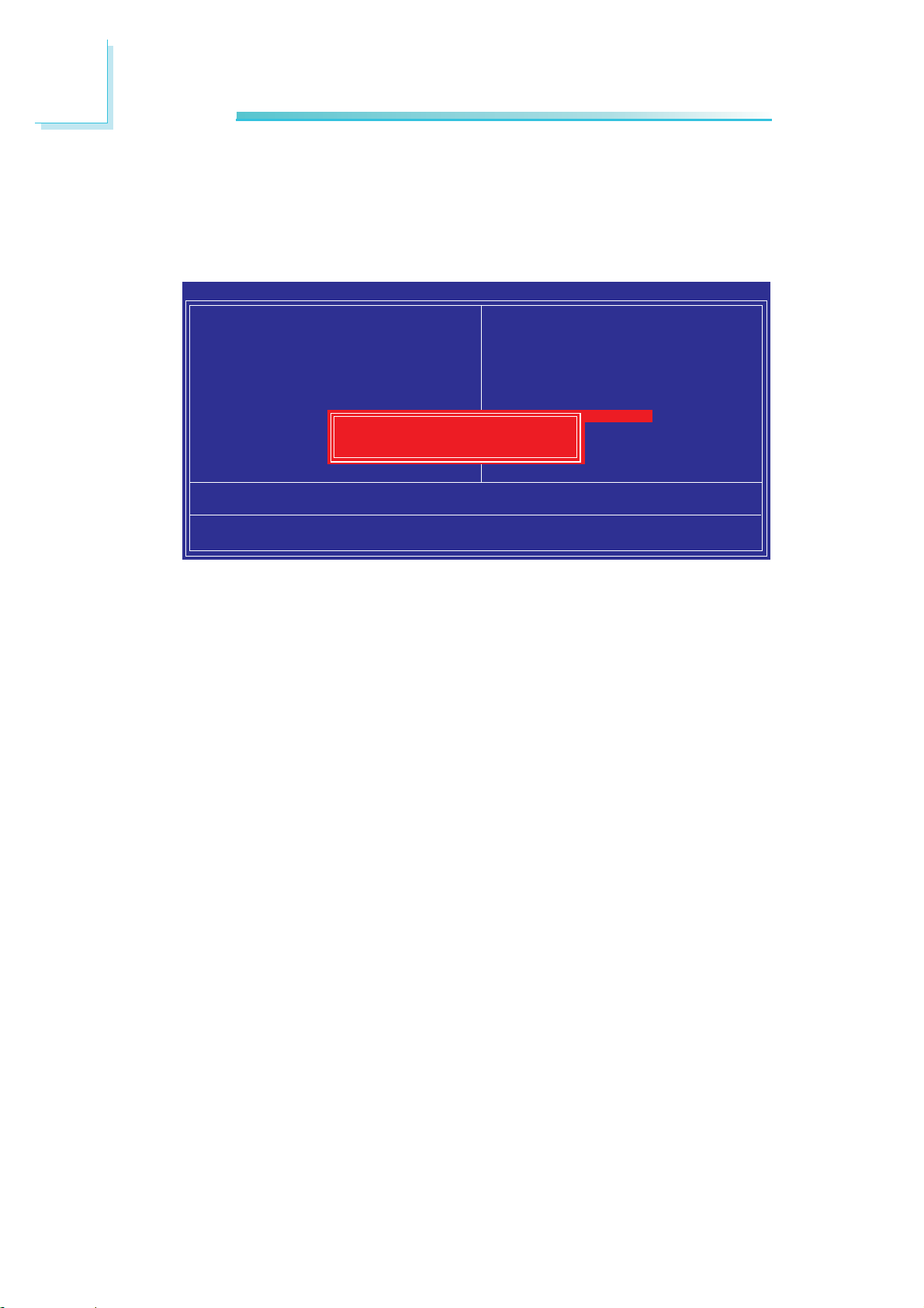
3
BIOS Setup
Save & Exit Setup
When all the changes have been made, highlight “Save & Exit Setup”
and press <Enter>.
Phoenix - AwardBIOS CMOS Setup Utility
X Standard CMOS Features
X Advanced BIOS Features
X Advanced Chipset Features
X Integrated Peripherals
X Power Management Setup
X PnP/PCI Configurations
X PC Health Status
Esc : Quit
F10 : Save & Exit Setup
SAVE to CMOS and EXIT (Y/N)?
Save Data to CMOS
Load Fail-Safe Defaults
Load Optimized Defaults
Set Supervisor Password
Set User Password
Save & Exit Setup
Exit Without Saving
↑ ↓ → ← : Select Item
Type “Y” and press <Enter>. The modifications you have made will
be written into the CMOS memory, and the system will reboot. You
will once again see the initial diagnostics on the screen. If you wish to
make additional changes to the setup, press <Ctrl> <Alt> <Del>
simultaneously after memory testing is done.
88
Page 89
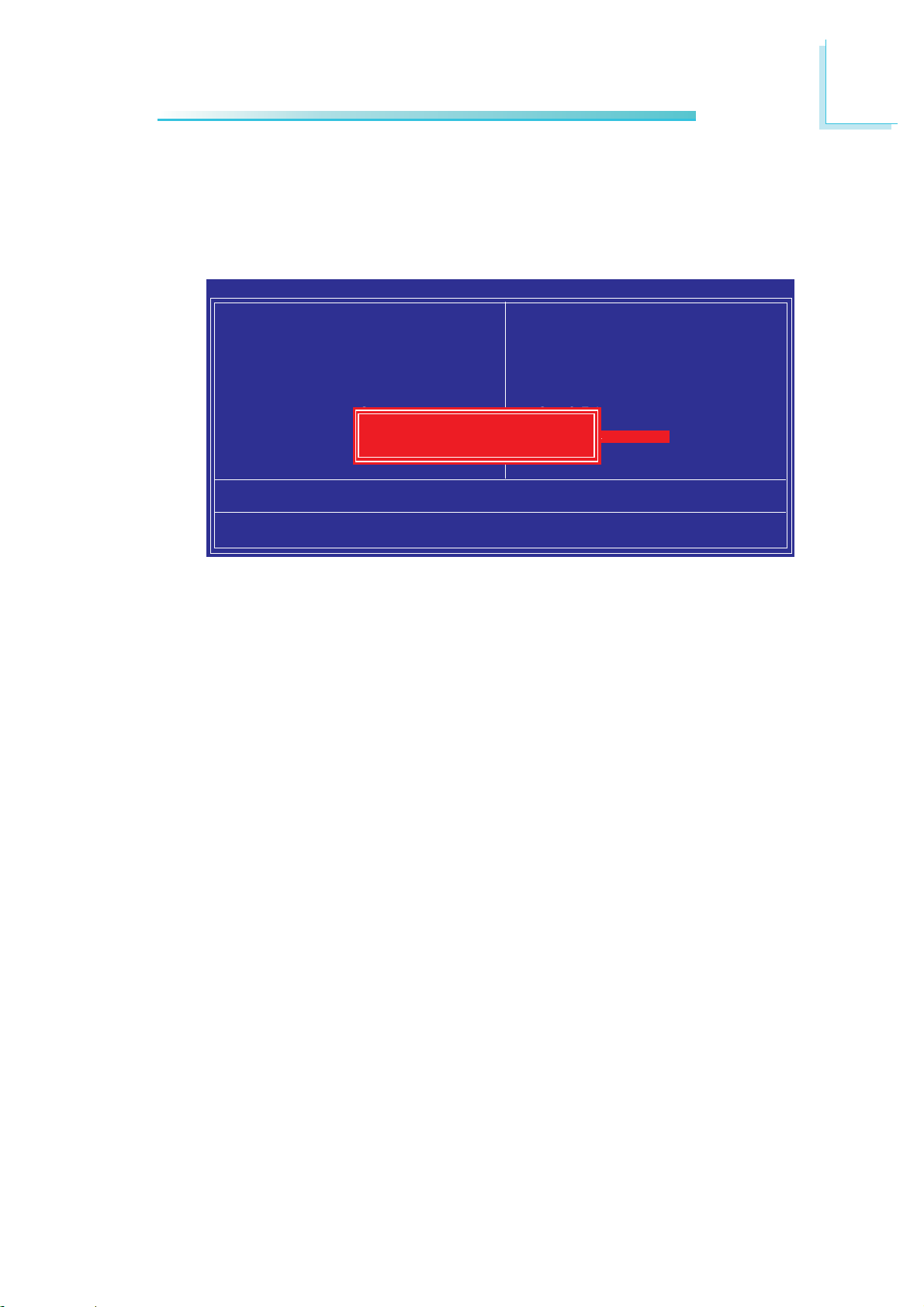
Exit Without Saving
When you do not want to save the changes you have made, highlight “Exit Without Saving” and press <Enter>.
BIOS Setup
3
Phoenix - AwardBIOS CMOS Setup Utility
X Standard CMOS Features
X Advanced BIOS Features
X Advanced Chipset Features
X Integrated Peripherals
X Power Management Setup
X PnP/PCI Configurations
X PC Health Status
Esc : Quit
F10 : Save & Exit Setup
Quit Without Saving (Y/N)? N
Abandon All Data
Load Fail-Safe Defaults
Load Optimized Defaults
Set Supervisor Password
Set User Password
Save & Exit Setup
Exit Without Saving
↑ ↓ → ← : Select Item
Type “Y” and press <Enter>. The system will reboot and you will
once again see the initial diagnostics on the screen. If you wish to
make any changes to the setup, press <Ctrl> <Alt> <Del> simultaneously aft
er memory testing is done.
89
Page 90

3
BIOS Setup
Updating the BIOS
To update the BIOS, you will need the new BIOS file and a flash
utility, AWDFLASH.EXE. Please contact technical support or your
sales representative for the files.
1. Save the new BIOS file along with the flash utility
AWDFLASH.EXE to a floppy disk.
2. Reboot the system and enter the Award BIOS Setup Utility to
set the first boot drive to “Floppy”.
3. Save the setting and reboot the system.
4. After the system booted from the floppy disk, execute the flash
utility by typing AWDFLASH.EXE. The following screen will appear.
Award BIOS Flash Utility V.8.15B
(C) Phoenix Technologies Ltd. All Rights Reserved.
(The current BIOS information will appear in this area.)
File Name to Program :
5. Type the new BIOS file name onto the gray area that is next to
“File Name to Program” then press <Enter>.
90
Page 91

BIOS Setup
6. The following will appear.
Do You Want to Save BIOS (Y/N)
This question refers to the current existing BIOS in your system.
We recommend that you save the current BIOS and its flash
utility; just in case you need to reinstall the BIOS. To save the
current BIOS, press <Y> then enter the file name of the current
BIOS. Otherwise, press <N>.
7. The following will then appear.
Press “Y” to Program or “N” to Exit
8. Press <Y> to flash the new BIOS.
3
91
Page 92

92
4
Supported Software
Chapter 4 - Supported Software
The CD that came with the system board contains drivers, utilities and software
applications required to enhance the performance of the system board.
Insert the CD into a CD-ROM drive. The autorun screen (Mainboard Utility CD)
will appear. If after inserting the CD, “Autorun” did not automatically start (which
is, the Mainboard Utility CD screen did not appear), please go directly to the root
directory of the CD and double-click “Setup”.
Page 93
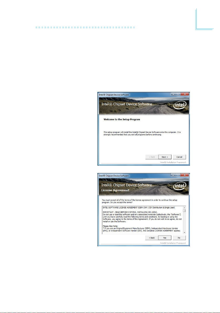
93
4
Supported Software
Drivers for Windows 7 / Windows Vista System
Intel Chipset Software Installation Utility
The Intel Chipset Software Installation Utility is used for updating Windows INF
les so that the Intel chipset can be recognized and congured properly in the
system.
To install the utility, click “Intel Chipset Software Installation Utility” on the main
menu.
1. Setup is now ready to install the utility. Click Next.
2. Read the license agreement
then click Yes.
Page 94
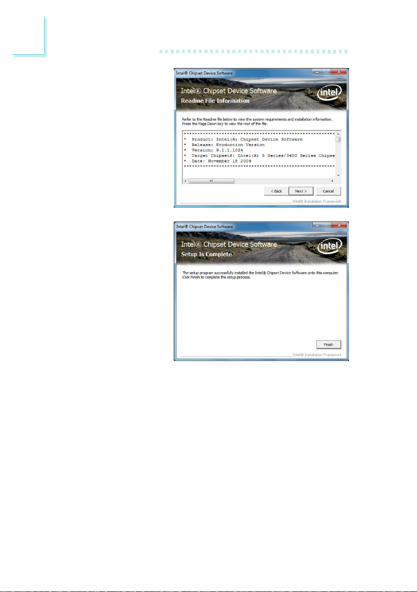
94
4
Supported Software
3. Go t hr ou gh the r ea dm e
document for system requirements and installation
tips then click Next.
5. Af te r c om ple ti ng i ns tal lation, click Finish to exit
setup.
Page 95
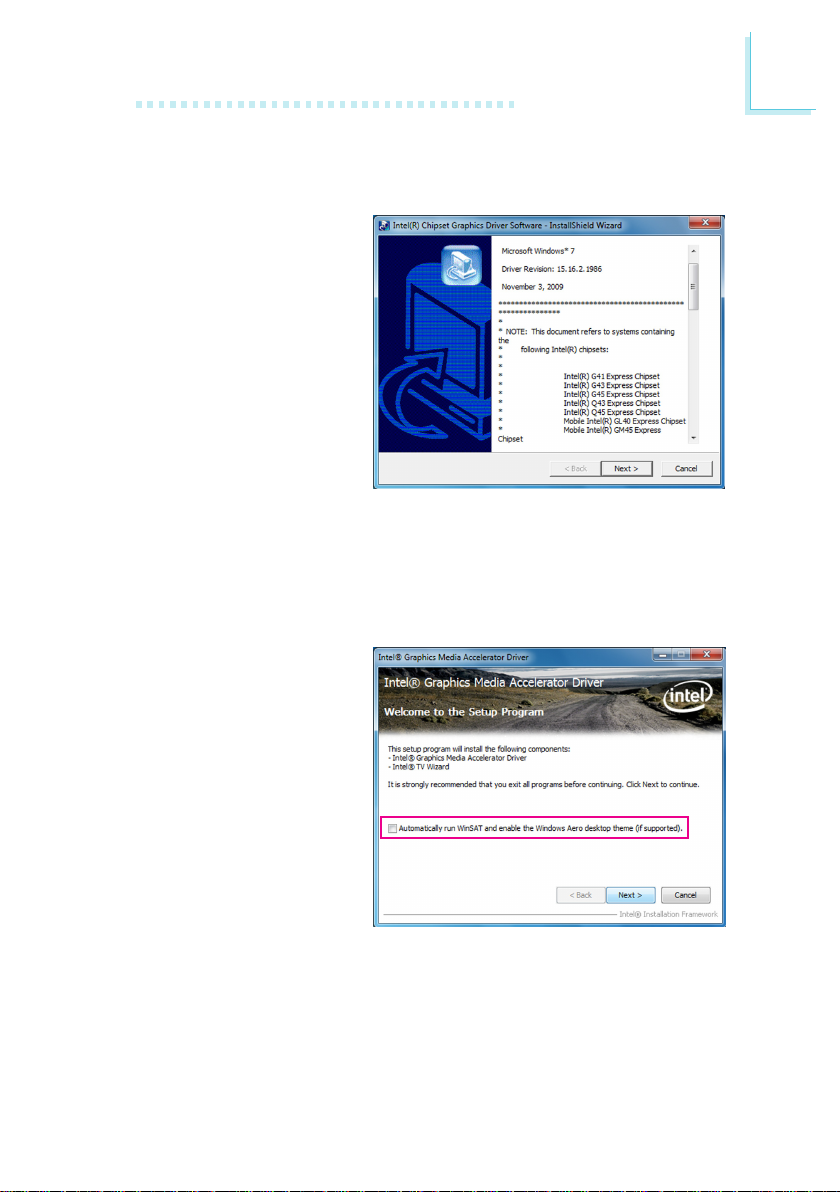
95
4
Supported Software
Intel Graphics Drivers
To install the driver, click “Intel Graphics Drivers” on the main menu.
1. Setup is now ready to install th e g rap hics dr ive r.
Click Next.
By default, the “Automatically run WinSAT and enable the Windows Aero
desktop theme” is enabled. With this enabled, after installing the graphics
driver and the system rebooted, the screen will turn blank for 1 to 2 minutes
(while WinSAT is running) before the Windows 7 / Windows Vista desktop appears. The “blank screen” period is the time Windows is testing the graphics
performance.
We recomme nd that you
skip this process by disabl ing this funct ion th en
click Next.
Page 96
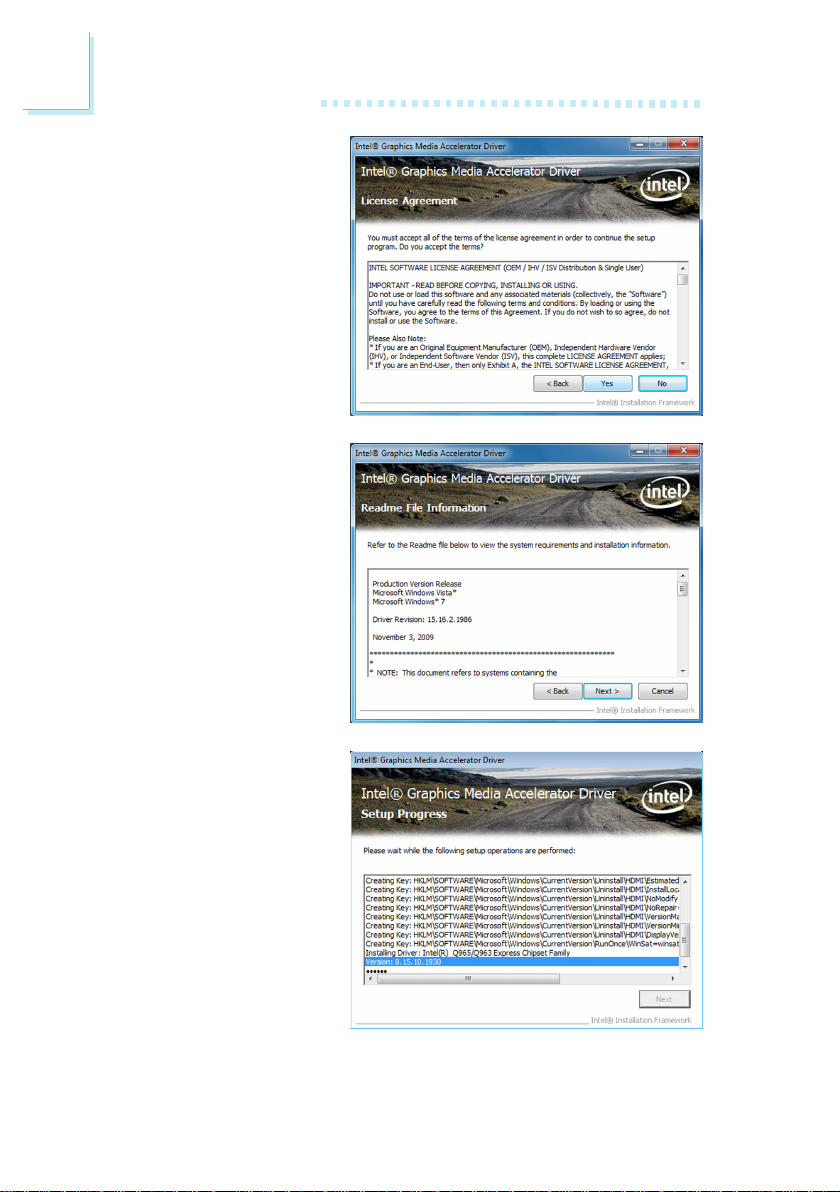
96
4
Supported Software
2. Read the license agreement
then click Yes.
3. Go t hr ough t he r eadme
document for system requirements and installation
tips then click Next.
4. Setup is now installing the
driver. Click Next to continue.
Page 97
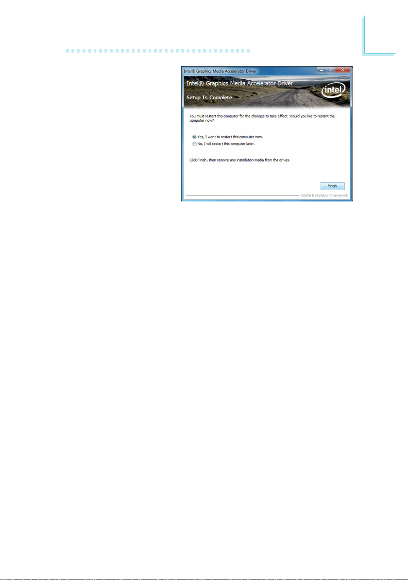
97
4
Supported Software
5. Click “Yes, I want to restart
thi s computer now” then
click Finish.
Restarting the system will
allow the new software installation to take effect.
Page 98
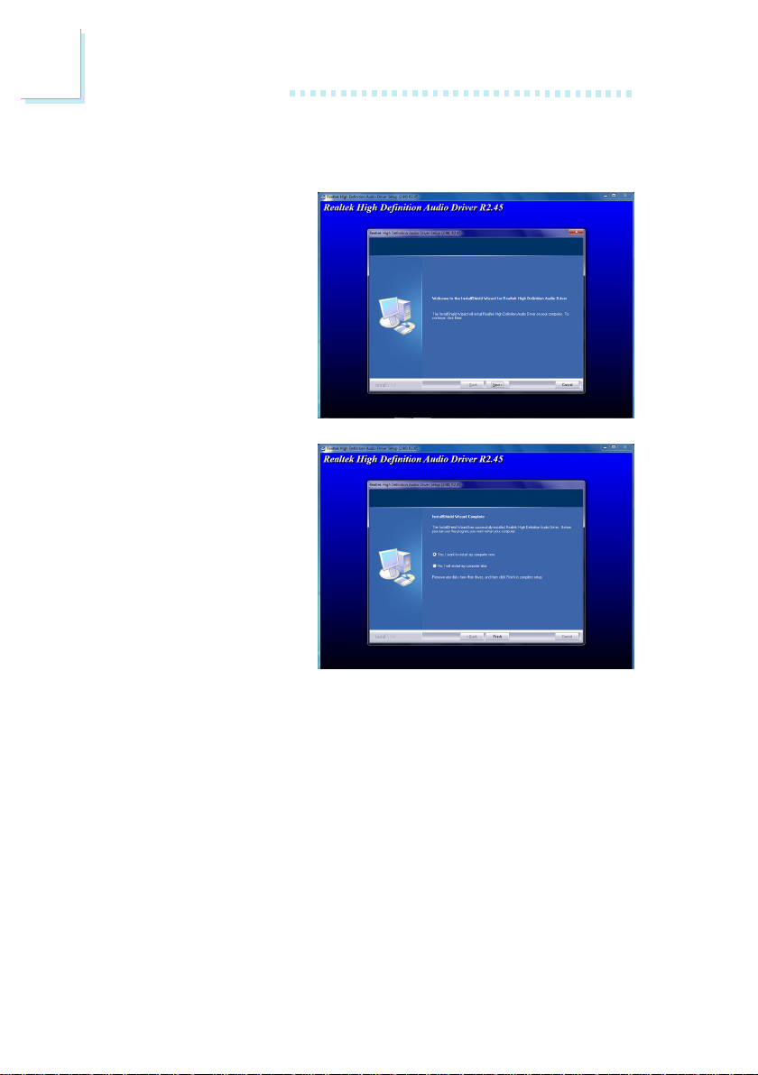
98
4
Supported Software
Audio Drivers
To install the driver, click “Audio Drivers” on the main menu.
1. Setup is now ready to install the driver. Click Next.
2. Follow the remainder of the
steps on the screen; clicking “Next” each time you
nish a step.
3. Click “Yes, I want to restart
my co mp uter n ow” th en
click Finish.
Restarting the system will
allow the new software installation to take effect.
Page 99
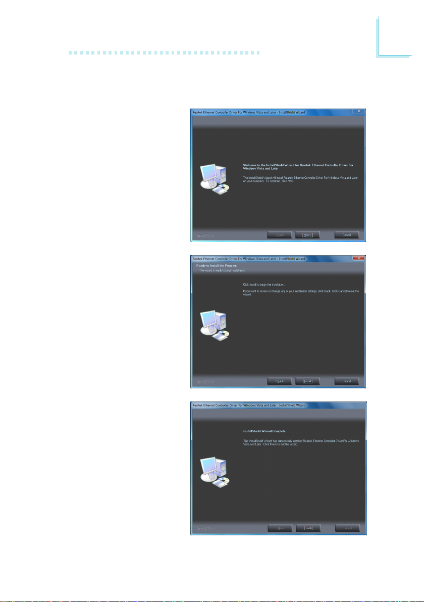
99
4
Supported Software
LAN Drivers
To install the driver, click “LAN Drivers” on the main menu.
1. Setup is ready to install the
driver. Click Next.
2. Click Install to begin the
installation.
3. After c ompleti ng installation, click Finish.
Page 100
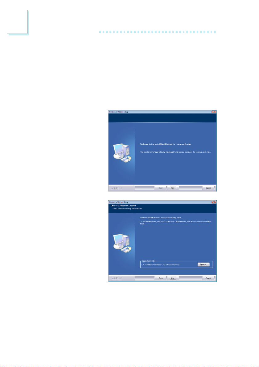
100
4
Supported Software
Hardware Monitor for Windows
The Hardware Monitor for Windows utility is capable of monitoring the system’s
temperature, fan speed, voltage, etc. and allows you to manually set a range
(Highest and Lowest Limit) to the items being monitored. If the settings/values
are over or under the set range, a warning message will pop-up. The utility can
also be congured so that a beeping alarm will sound whenever an error occurs.
We recommend that you use the “Default Setting” which is the ideal setting that
would keep the system in good working condition.
To install the utility, click “Hardware Monitor for Windows” on the main menu.
1. Setup is now ready to install the utility. Click Next.
2. Click Next to install or click
Browse to sel ect another
folder.
 Loading...