

Page 1

935-DX5831-004G
08600850A
System Board
User’s Manual
Page 2

Copyright
This publication contains information that is protected by copyright. No part of it
may be reproduced in any form or by any means or used to make any transformation/adaptation without the prior written permission from the copyright
holders.
This publication is provided for informational purposes only. The manufacturer
makes no representations or warranties with respect to the contents or use of
this manual and specifically disclaims any express or implied warranties of
merchantability or fitness for any particular purpose. The user will assume the
entire risk of the use or the results of the use of this document. Further, the
manufacturer reserves the right to revise this publication and make changes to its
contents at any time, without obligation to notify any person or entity of such
revisions or changes.
© 2008. All Rights Reserved.
Trademarks
Windows® 2000 and Windows® XP are registered trademarks of Microsoft
Corporation. Award is a registered trademark of Award Software, Inc. Other
trademarks and registered trademarks of products appearing in this manual are
the properties of their respective holders.
FCC and DOC Statement on Class B
This equipment has been tested and found to comply with the limits for a Class
B digital device, pursuant to Part 15 of the FCC rules. These limits are designed
to provide reasonable protection against harmful interference when the equipment is operated in a residential installation. This equipment generates, uses and
can radiate radio frequency energy and, if not installed and used in accordance
with the instruction manual, may cause harmful interference to radio
communications. However, there is no guarantee that interference will not occur
in a particular installation. If this equipment does cause harmful interference to
radio or television reception, which can be determined by turning the equipment
off and on, the user is encouraged to try to correct the interference by one or
more of the following measures:
• Reorient or relocate the receiving antenna.
• Increase the separation between the equipment and the receiver.
• Connect the equipment into an outlet on a circuit different from that to
which the receiver is connected.
• Consult the dealer or an experienced radio TV technician for help.
Notice:
1. The changes or modifications not expressly approved by the party responsible for compliance could void the user's authority to operate the equipment.
2. Shielded interface cables must be used in order to comply with the emission
limits.
Page 3

Table of Contents
About this Manual................................................................................
Warranty.................................................................................................
Static Electricity Precaution................................................................
Safety Measures.....................................................................................
About the Package...............................................................................
Before Using the System Board.........................................................
System Board Layout............................................................................
English.....................................................................................................
................................................................................................
................................................................................................
....................................................................................................
....................................................................................................
Appendix A - General Debug LED POST and
Troubleshooting ...................................................................................
4
4
5
5
6
6
7
8
36
66
95
129
158
Page 4

1
4
Introduction
About this Manual
An electronic file of this manual is included in the CD. To view the
user’s manual in the CD, insert the CD into a CD-ROM drive. The
autorun screen (Main Board Utility CD) will appear. Click the
“TOOLS” icon then click “Manual” on the main menu.
For additional information on the system board, please download
the complete version of the manual from DFI’s website. Visit www.
dfi.com.
Warranty
1. Warranty does not cover damages or failures that arised from
misuse of the product, inability to use the product, unauthorized
replacement or alteration of components and product
specifications.
2. The warranty is void if the product has been subjected to physical abuse, improper installation, modification, accidents or unauthorized repair of the product.
3. Unless otherwise instructed in this user’s manual, the user may
not, under any circumstances, attempt to perform ser vice, adjustments or repairs on the product, whether in or out of warranty.
It must be returned to the purchase point, factory or authorized
service agency for all such work.
4. We will not be liable for any indirect, special, incidental or
consequencial damages to the product that has been modified
or altered.
Page 5

1
5
Introduction
Static Electricity Precautions
It is quite easy to inadvertently damage your PC, system board,
components or devices even before installing them in your system
unit. Static electrical discharge can damage computer components
without causing any signs of physical damage. You must take extra
care in handling them to ensure against electrostatic build-up.
1. To prevent electrostatic build-up, leave the system board in its
anti-static bag until you are ready to install it.
2. Wear an antistatic wrist strap.
3. Do all preparation work on a static-free surface.
4. Hold the device only by its edges. Be careful not to touch any of
the components, contacts or connections.
5. Avoid touching the pins or contacts on all modules and
connectors. Hold modules or connectors by their ends.
Important:
Electrostatic discharge (ESD) can damage your processor, disk
drive and other components. Perform the upgrade instruction
procedures described at an ESD workstation only. If such a
station is not available, you can provide some ESD protection
by wearing an antistatic wrist strap and attaching it to a metal
part of the system chassis. If a wrist strap is unavailable, establish and maintain contact with the system chassis
throughout any procedures requiring ESD protection.
Safety Measures
To avoid damage to the system:
•Use the correct AC input voltage range
..
..
.
To reduce the risk of electric shock:
• Unplug the power cord before removing the system chassis
cover for installation or servicing. After installation or servicing,
cover the system chassis before plugging the power cord.
Battery:
• Danger of explosion if battery incorrectly replaced.
• Replace only with the same or equivalent type recommend
by
the manufacturer.
• Dispose of used batteries according to local ordinance.
Page 6

1
6
Introduction
About the Package
The system board package contains the following items. If any of
these items are missing or damaged, please contact your dealer or
sales representative for assistance.
; One system board
; One IDE round cable
; One floppy round cable
; Two Serial ATA data cables
; One power cable with 2 Serial ATA power connectors
; Smart connectors
; One I/O shield
; One DVD disc
; One user’s manual
The system board and accessories in the package may not come
similar to the information listed above. This may differ in accordance
to the sales region or models in which it was sold. For more information about the standard package in your region, please contact
your dealer or sales representative.
Before Using the System Board
Before using the system board, prepare basic system components.
If you are installing the system board in a new system, you will need
at least the following internal components.
• A CPU
• Memory module
• Storage devices such as hard disk drive, CD-ROM, etc.
You will also need external system peripherals you intend to use
which will normally include at least a keyboard, a mouse and a video
display monitor.
Page 7
1
7
Introduction
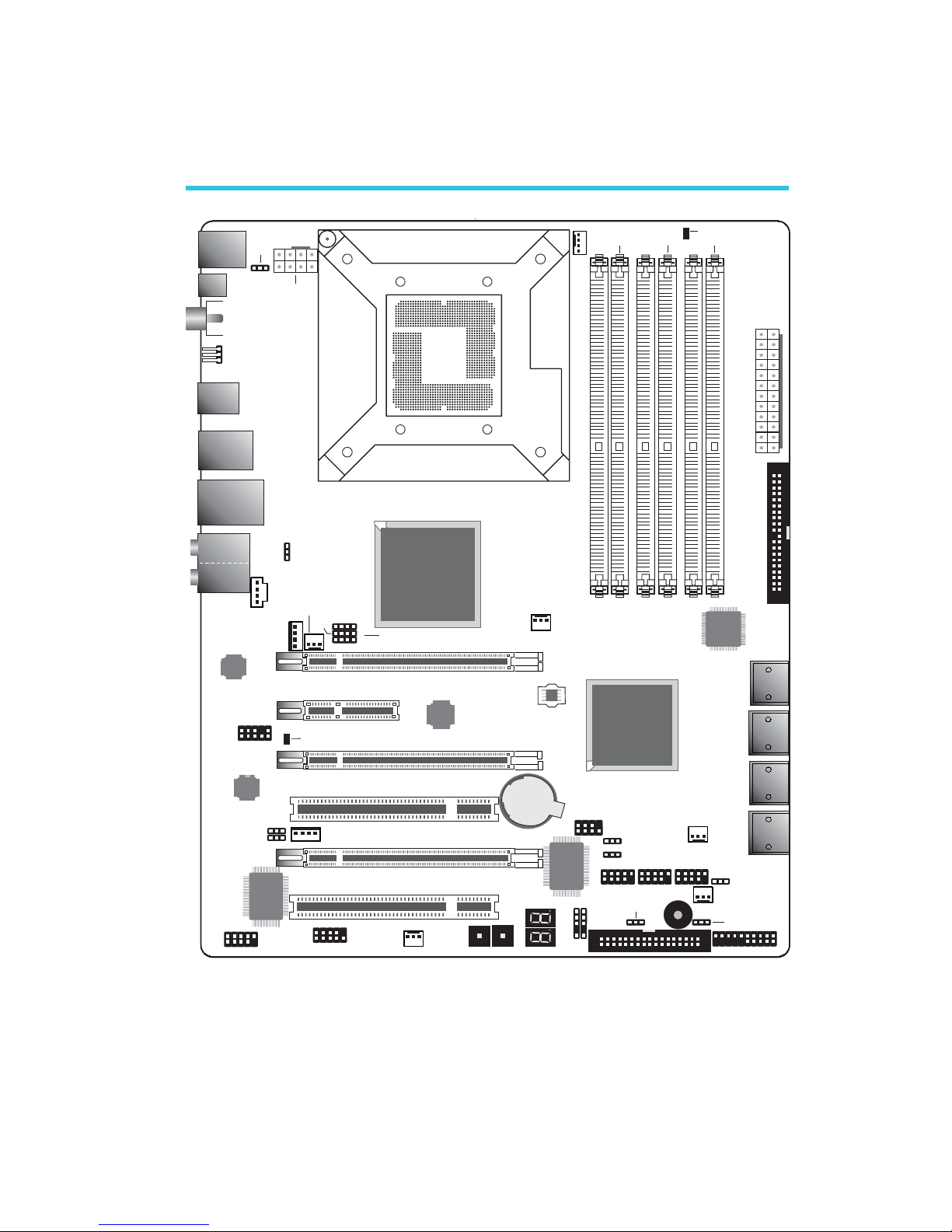
System Board Layout
Front panel
1
Reset Power
SATA 5
SATA 6
SATA 3
SATA 4
SATA 1
SATA 2
SATA 7
SATA 8
1 1
IrDA
CIR
1
1394-1
1
System
fan
1
1
1
1
1
1
Fan 2
1
Fan 1
PCIE 2
NB fan
5V/12V
1
power
PCI 2
1
1
1
CPU fan
1
JP15
J13P
JP14
1
12V power
Mouse
KB
2412
1
13
ATX
power
1
IDE
1
1
Intel
X58
Battery
JMicron
JMB363
LGA 1366
USB 2-3
Clear CMOS
(J )P2
Intel
ICH10R
1
1
1
1
Speaker On/Off
(J )P8
Safe boot (J )P1
Secondary RTC
Reset (J )P12
PCIE 1
PCIE 3
PCIE 4
1
1
DIMM 1
DIMM 2 DIMM 4
DIMM 3
DIMM 6
DIMM 5
Fan 3
SPI Flash
BIOS
PS/2 power
select
(J )P7
DRAM Power LED
USB 6-11
select (JP5)
power
Realtek
ALC889
Marvell
88E8053
PCI 1
JP26
JP27
1
CPU FSB select
(JP13-JP15)
5V/12V
power
ITE
IT8718F
VIA
VT6308P
COM
1
1
USB 0-5 power
select (JP6)
USB 4-5 USB 0-1
1
2
7
8
Download
Flash BIOS
CPU_VTT select
(JP26-JP27)
Standby
Power LED
1
LAN
USB 10-11
Line-in
Front R/L
Mic-in
Center/
Subwoofer
Side R/L
Rear R/L
USB 6-7
Optical
S/PDIF-out
1
Coaxial RCA
S/PDIF-out
Clear CMOS
(JP10)
1394-0
USB 8-9
1
CD-in
Front audio
1
FDD
Page 8

E
8
English
English
Chapter 1 - Specifications
Processor
Chipset
QPI
System Memory
Expansion Slots
BIOS
Graphics Processing
Unit (GPU)
Audio
LAN
IEEE 1394
• LGA 1366 socket for Intel® CoreTM i7 processors
• Intel® QuickPath Interconnect (QPI) technology - point-to-point
interface that connects to X58; providing a dynamically
scalable interconnect for increased bandwidth, lower latency
and stability
• Integrated Memory Controller (IMC) supports 3 channels of
DDR3
• Intel Hyper-Threading Technology delivers 8-threaded
performance
•6-phase digital PWM provides stable voltage to the CPU
• Intel
®
chipset
- Northbridge: Intel® X58 Express chipset
- Southbridge: Intel® ICH10R
• System bus - 4.8GT/s to 6.4GT/s
• Six 240-pin DDR3 DIMM sockets
• DDR3 800/1066/1333/1600(O.C.) MHz DIMMs
• Triple-channel memory architecture
• Supports up to 24GB system memory
• Delivers up to 43.2GB/s bandwidth
• Unbuffered x8/x16, non-ECC and ECC, up to 4Gb DDR3
devices
• 3 PCI Express (Gen 2) x16 slots
- 2-way SLI or Quad CrossFireX configuration at x16/x16/x4
transfer rate lanes
• 1 PCI Express x4 slot
• 2 PCI slots
• Award BIOS
• 8Mbit SPI flash memory
• CMOS Reloaded
• Multiple GPUs
- 3 graphics cards in 2-way SLI or Quad CrossFireX
configuration
• Realtek ALC889 High Definition audio CODEC
• 8-channel audio output
• 108dB Signal-to-Noise ratio (SNR) playback (DAC) quality
and 104dB SNR recording (ADC) quality
• Marvell 88E8053 PCIE Gigabit LAN controller with Teaming
technology
• Fully compliant to IEEE 802.3 (10BASE-T), 802.3u (100BASETX) and 802.3ab (1000BASE-T) standards
• VIA VT6308P
• Supports two 100/200/400 Mb/sec IEEE 1394a ports
Page 9

E
9
English
English
Storage
Rear Panel I/O
Internal I/O
Power Management
Hardware Monitor
PCB
• Intel ICH10R chip
- Intel Matrix Storage technology
- Supports up to 6 SATA devices
- SATA speed up to 3Gb/s
- RAID 0, RAID 1, RAID 0+1 and RAID 5
• JMicron JMB363 PCI Express to SATA and PATA host controller
- Supports up to 2 UltraDMA 100Mbps IDE devices
- Supports 2 SATA devices
- SATA speed up to 3Gb/s
- RAID 0 and RAID 1
• 1 mini-DIN-6 PS/2 mouse port
• 1 mini-DIN-6 PS/2 keyboard port
• 1 optical S/PDIF-out port
• 1 coaxial RCA S/PDIF-out port
• 6 USB 2.0/1.1 ports
• 1 IEEE 1394 port
• 1 RJ45 LAN port
• Center/subwoofer, rear R/L and side R/L jacks
• Line-in, line-out (front R/L) and mic-in jacks
• 3 connectors for 6 additional external USB 2.0 ports
• 1 connector for an external COM port
• 1 connector for an external IEEE 1394 port
• 1 front audio connector
• 1 CD-in connector
• 1 IrDA connector and 1 CIR connector
• 8 Serial ATA connectors
• 1 40-pin IDE connector and 1 floppy connector
• 1 24-pin ATX power connector
• 1 8-pin 12V power connector
• 2 4-pin 5V/12V power connectors (FDD type)
• 1 front panel connector
• 6 fan connectors
• 1 download flash BIOS connector
• 1 diagnostic LED
• EZ touch switches (power switch and reset switch)
• ACPI and OS Directed Power Management
• ACPI STR (Suspend to RAM) function
• Wake-On-PS/2 / Wake-On-USB Keyboard/Mouse
• Wake-On-LAN and Wake-On-Ring
• RTC timer to power-on the system
• AC power failure recovery
• Monitors CPU/system/Northbridge temperature and overheat alarm
• Monitors Vcore/Vdimm/Vnb/VCC5/12V/V5sb/Vbat voltages
• Monitors the speed of the cooling fans
• CPU Overheat Protection function monitors CPU temperature
and fan during system boot-up - automatic shutdown upon system overheat
• 6 layers, ATX form factor ;
• 24.5cm (9.64") x 30.5cm (12")
Page 10
E
10
English
English
1
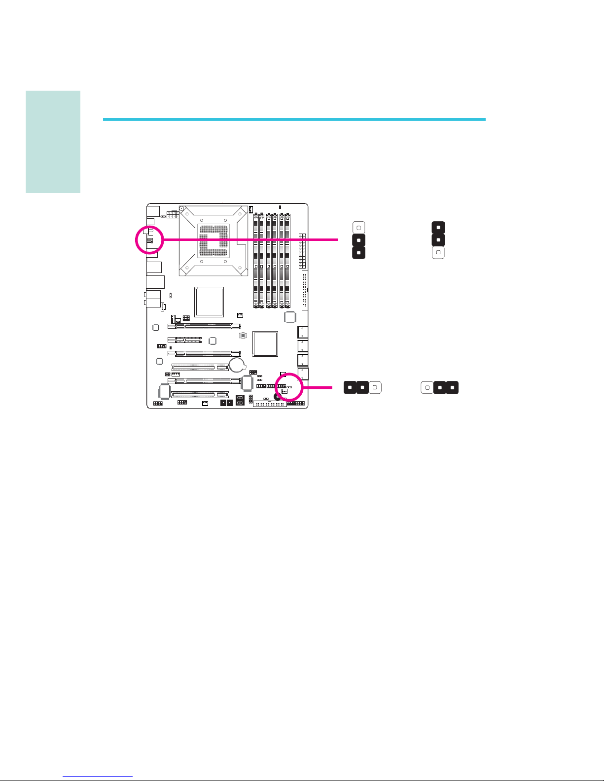
Chapter 2 - Hardware Installation
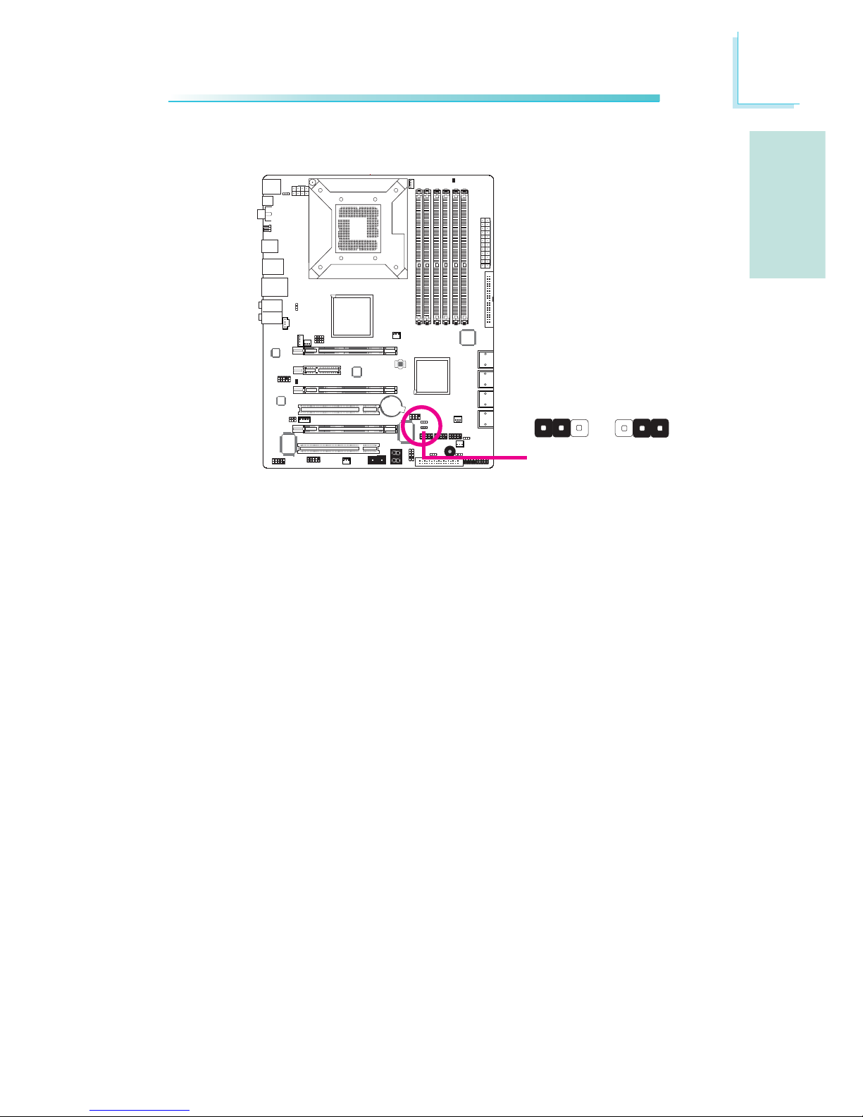
Jumper Settings
Clear CMOS Data
2-3 On:
Clear CMOS Data
1-2 On: Normal
(default)
X
JP2
312 312
JP10
X
2-3 On:
Clear CMOS Data
1-2 On: Normal
(default)
1
3
2
1
3
2
If you encounter the following,
a) CMOS data becomes corrupted.
b) You forgot the supervisor or user password.
c) The overclocked settings in the BIOS resulted to the system’s in-
stability or caused system boot up problems.
you can reconfigure the system with the default values stored in the
ROM BIOS.
JP10 is accessible from the rear panel of the system. This provides
convenience by allowing you to clear the CMOS without having to
remove the chassis cover.
To load the default values stored in the ROM BIOS, please follow
the steps below.
1. Power-off the system then unplug the power cord.
2. Set JP2 or JP10 pins 2 and 3 to On. Wait for a few seconds
and set JP2 or JP10 back to its default setting, pins 1 and 2 On.
3. Now plug the power cord then power-on the system.
Page 11
E
11
English
English
1
1
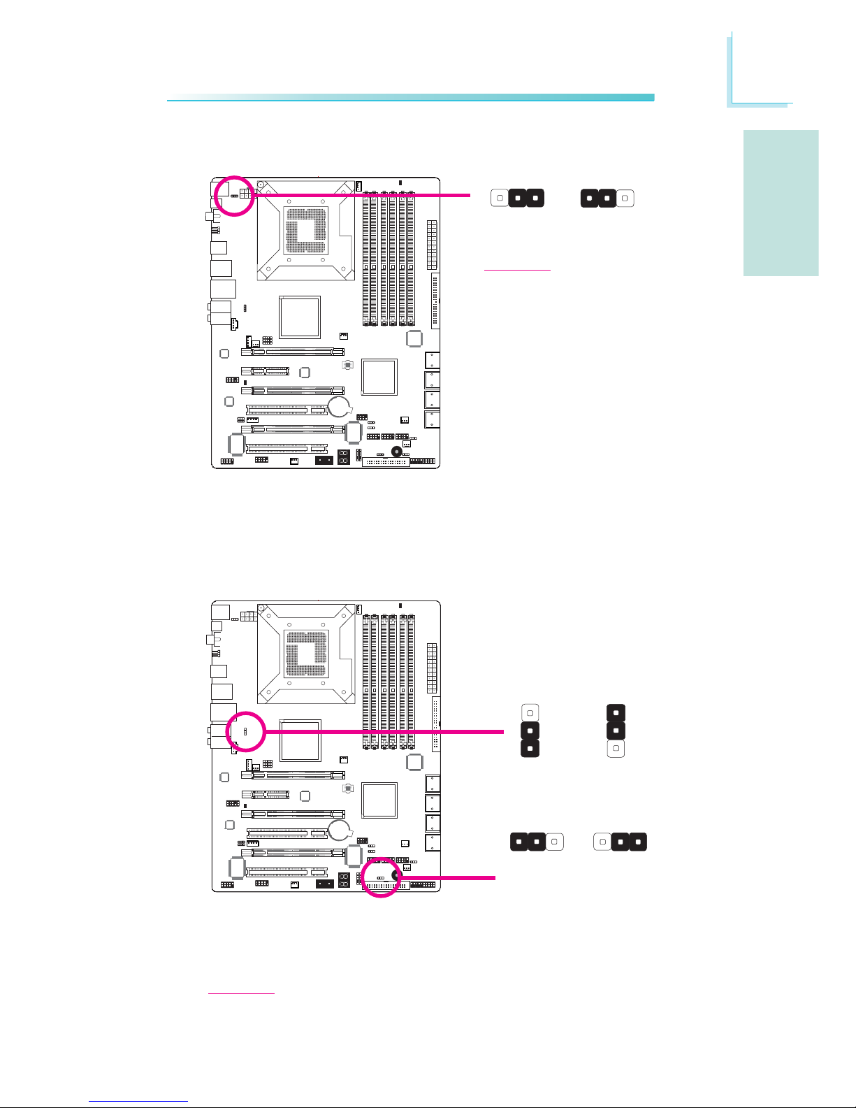
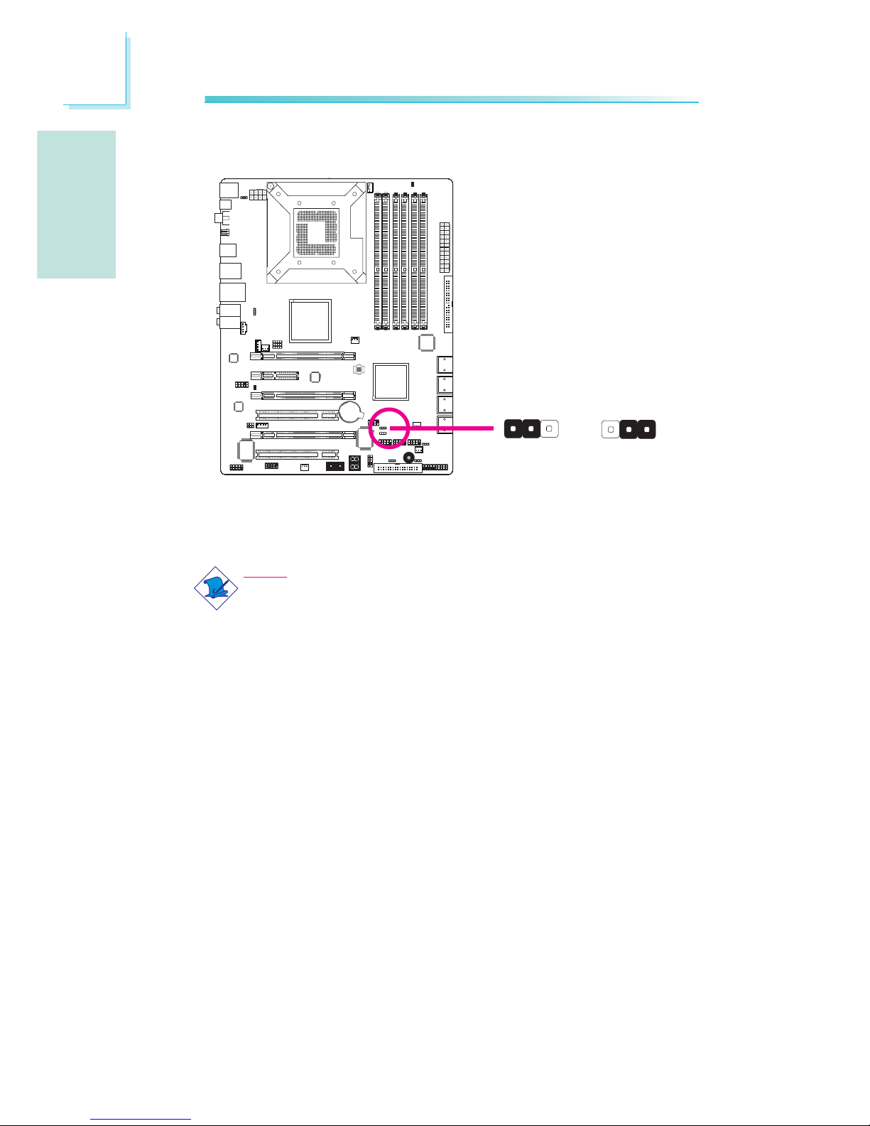
PS/2 Power Select
Selecting 5VSB will allow you to use the PS/2 keyboard or PS/2
mouse to wake up the system.
X
JP7
2-3 On:
5VSB
1-2 On: 5V
(default)
31
2
312
USB Power Select
X
USB 6-11
(JP5)
X
USB 0-5
(JP6)
2-3 On:
5VSB
1-2 On: 5V
(default)
1
3
2
1
3
2
2-3 On:
5VSB
1-2 On: 5V
(default)
Selecting 5VSB will allow you to use the USB keyboard or USB
mouse to wake up the system..
Important:
The 5VSB power source of your
power supply must support
≥720mA.
Important:
The 5VSB power source of your power supply must support ≥1.5A (2 devices)
or ≥2A (3 or more devices).
312 312
Page 12
E
12
English
English
1
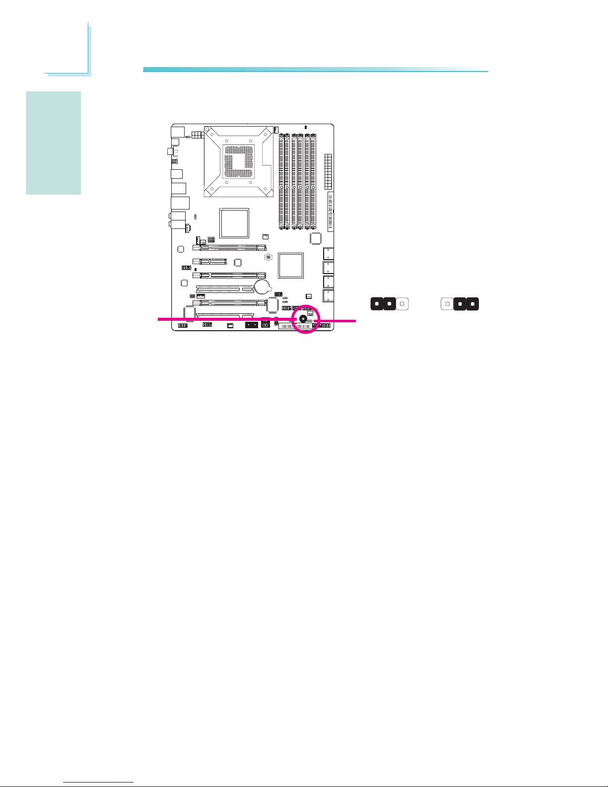
The system board is equipped with a buzzer which serves as the
PC’s speaker. By default the buzzer is “on” allowing you to hear the
system’s beep messages and warnings. If you intend to use an external speaker, turn this function off by setting JP8 pins 1 and 2 to On.
Speaker On/Off Select
JP8
2-3 On:
Speaker On
(default)
1-2 On:
Speaker Off
Buzzer
312 312
X
Page 13
E
13
English
English
1
This jumper is used to safely reboot the system whenever the system hangs and you are unable to restart the system.
1. Power-off the system then unplug the power cord.
2. Set pins 2 and 3 to On. Wait for a few seconds then set the
jumper back to its default setting, pins 1 and 2 On.
3. Plug the power cord then power-on the system. The system will
reboot normally without losing all data stored in the CMOS.
Safe Boot
1-2 On:
Default
312 312
X
JP1
2-3 On:
Safe boot
Page 14
E
14
English
English
1
Secondary RTC Reset
When the RTC battery is removed, this jumper resets the
manageability register bits in the RTC.
Note:
1. The SRTCRST# input must always be high when all other
RTC power planes are on.
2. In the case where the RTC battery is dead or missing on
the platform, the SRTCRST# pin must rise before the
RSMRST# pin.
312
312
X
JP12
2-3 On:
RTC reset
1-2 On: Normal
(default)
Page 15
E
15
English
English
4
1
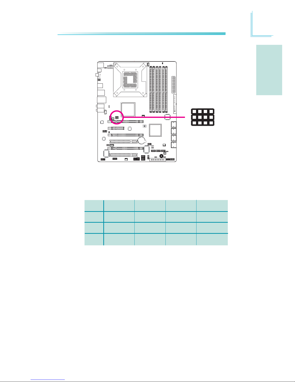
CPU FSB Select
X
By default, JP13 to JP15 are set to pins 1 and 2 On. This setting will
allow the system to automatically run according to the CPU’s FSB. If
you want to change the setting, please refer to the table below.
JP15
JP14
JP13
By CPU
1-2 On
1-2 On
1-2 On
FSB 800
3-4 On
2-3 On
2-3 On
FSB 1066
2-3 On
2-3 On
2-3 On
FSB 1333
2-3 On
2-3 On
3-4 On
JP15
132
JP14
JP13
Page 16
E
16
English
English
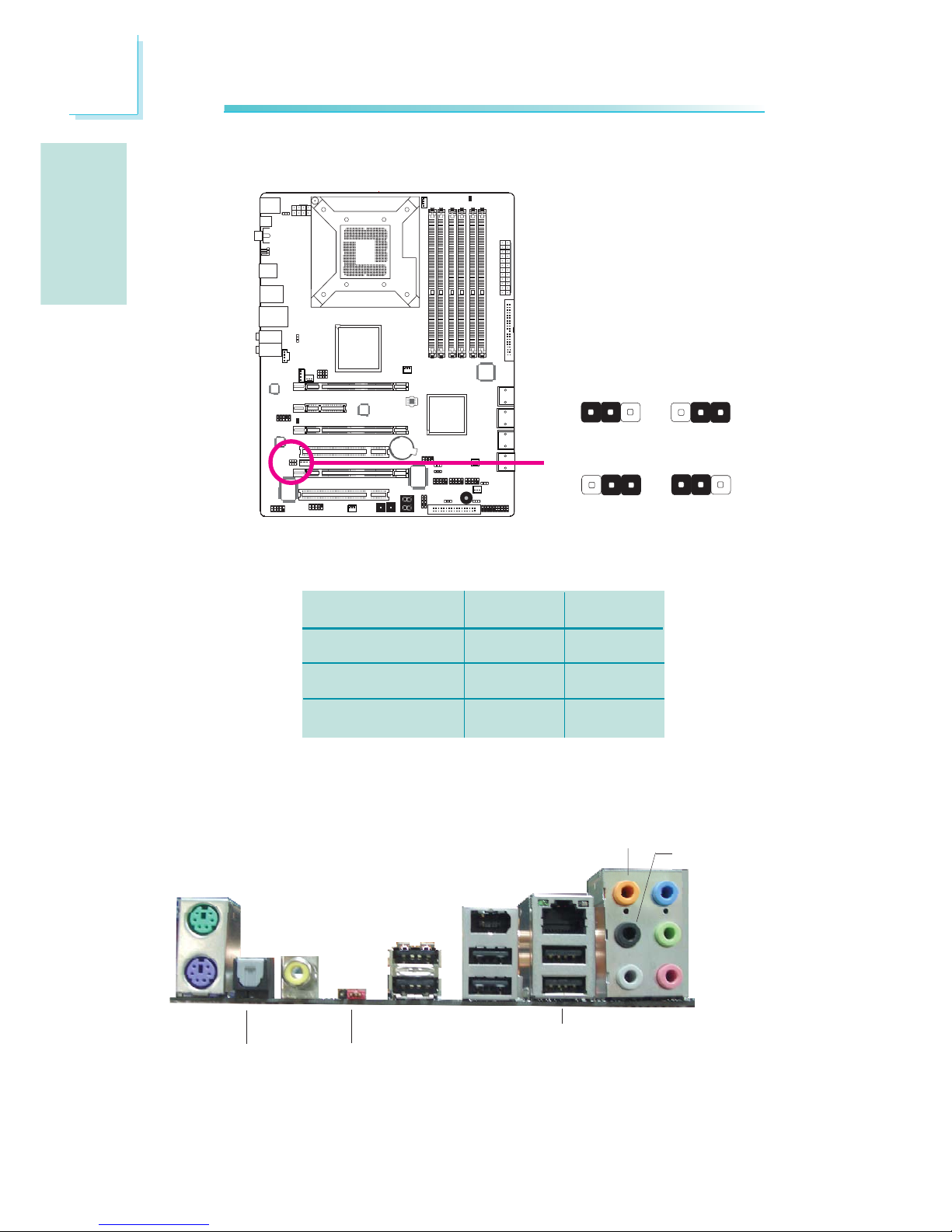
Rear Panel I/O Ports
1
CPU_VTT Select
X
312
312
31
2
312
1-2 On 2-3 On
1-2 On 2-3 On
JP26
JP27
CPU_VTT
1.2V (default)
1.4V
1.6V
JP26
1-2 On
2-3 On
2-3 On
JP27
1-2 On
2-3 On
1-2 On
JP26 and JP27 are used to select the CPU’s voltage.
PS/2 K/B
Optical
S/PDIF-out
USB 8-9
USB 10-11
Coaxial
S/PDIF-out
Mic-in
Side R/L
Center/
Subwoofer
Rear R/L
Line-in
Front R/L
LAN
PS/2
Mouse
USB 6-7
Clear
CMOS
jumper
1394-0
Page 17
E
17
English
English
1
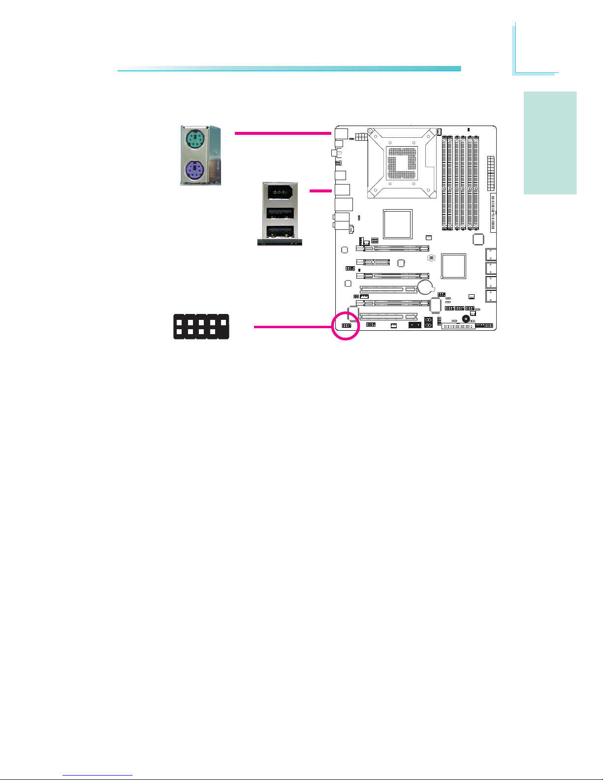
PS/2 Mouse and PS/2 Keyboard Ports
These ports are used to connect a PS/2 mouse and a PS/2
keyboard.
IEEE 1394 Ports
The IEEE 1394-0 port is used to connect audio/video devices or
storage peripherals. The 10-pin connector allows you to connect an
additional 1394 port. Your 1394 port may come mounted on a
card-edge bracket. Install the card-edge bracket to an available slot
at the rear of the system chassis then connect the 1394 port cable
to this connector.
PS/2 Ports and IEEE 1394 Ports
W
1394-0
W
PS/2 Mouse
PS/2 KB
1394-1
W
+12V (fused)
1
TPA+
Ground
TPB+
+12V (fused)
Key
TPA-
Ground
TPB-
Ground
2
10
9
Page 18
E
18
English
English
1
LAN
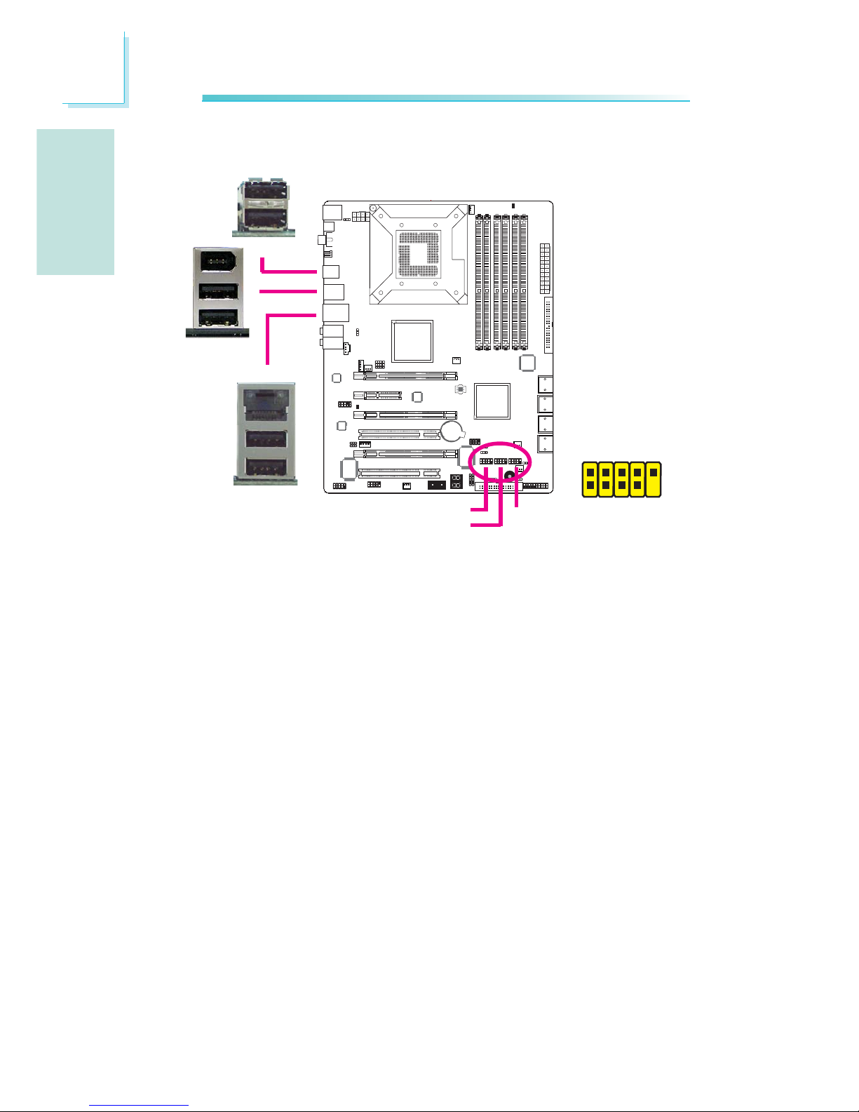
USB Ports and LAN Port
USB Ports
The USB ports are used to connect USB 2.0/1.1 devices. The 10-pin
connectors allow you to connect 6 additional USB 2.0/1.1 ports.
Your USB ports may come mounted on a card-edge bracket. Install
the card-edge bracket to an available slot at the rear of the system
chassis then connect the USB port cables to these connectors.
LAN Port
The LAN port allows the system board to connect to a local area
network by means of a network hub.
W
W
W
USB 11
USB 10
USB 9
USB 8
1
VCC
-Data
+Data
GND
Key
VCC
-Data
+Data
GND
N. C.
2
10
9
USB 4-5
USB 2-3
USB 0-1
USB 7
USB 6
Page 19
E
19
English
English
1
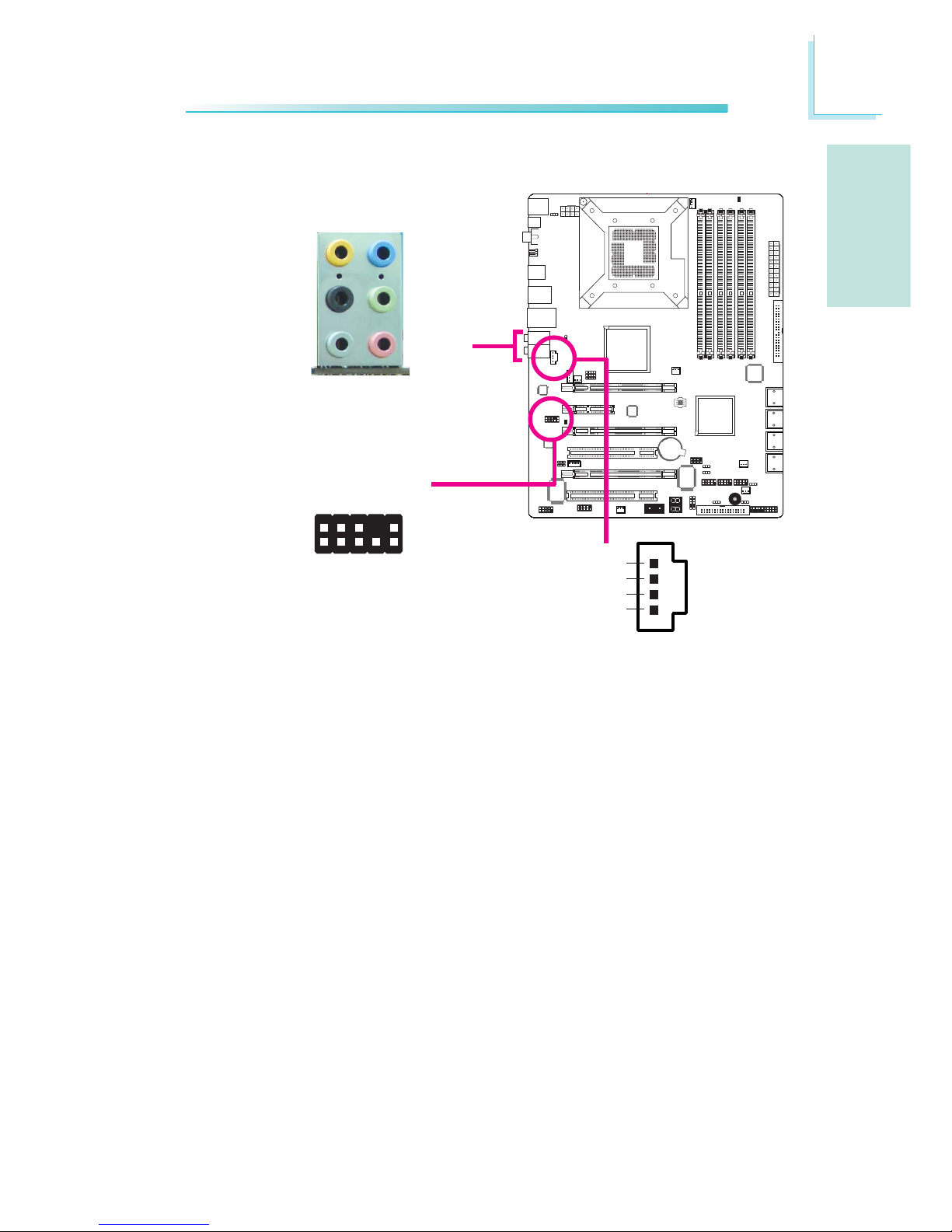
Rear Panel Audio
Center/Subwoofer Jack (Orange)
This jack is used to connect to the center and subwoofer speakers of the audio system.
Rear Right/Left Jack (Black)
This jack is used to connect to the rear right and rear left speakers of the audio system.
Side Right/Left Jack (Gray)
This jack is used to connect to the side left and side right speakers of the audio system.
Line-in (Light Blue)
This jack is used to connect any audio devices such as Hi-fi set,
CD player, tape player, AM/FM radio tuner, synthesizer, etc.
Line-out - Front Right/Left Jack (Lime)
This jack is used to connect to the front right and front left
speakers of the audio system.
Audio and CD-In
W
W
Rear audio
Front audio
Front R/L
Line-in
Mic-in
Rear R/L
Center/
Subwoofer
Side R/L
1
2
10
Mic-L
Mic-R
Line-out-R
Front-sense
Line-out-L
GND
Presense-signal
Mic-jack-sense
Key
Line-out-jack-sense
9
4
1
Left audio channel
Right audio channel
Ground
Ground
W
CD-in
Page 20
E
20
English
English
1
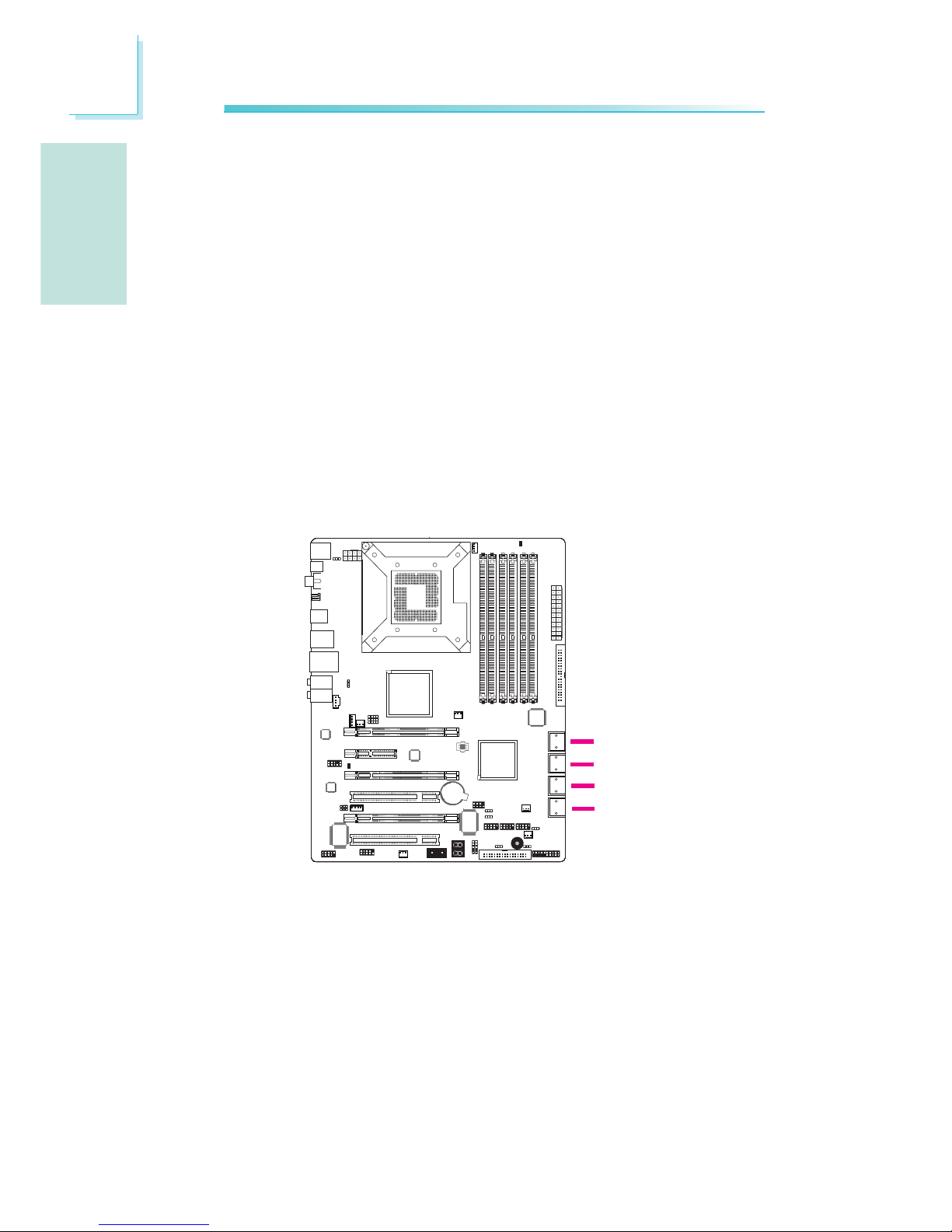
Serial ATA Connectors
The Serial ATA (SATA) connectors are used to connect Serial ATA
drives. Connect one end of the Serial ATA cable to a Serial ATA
connector and the other end to your Serial ATA device.
ICH10R supports SATA 1 to SATA 6.
JMB363 supports SATA 7 and SATA 8.
Configuring RAID
Refer to the RAID chapter in this manual for more information
about creating RAID on Serial ATA drives.
SATA 1-2
SATA 7-8
I/O Connectors
SATA 5-6
SATA 3-4
Mic-in Jack (Pink)
This jack is used to connect an external microphone.
Front Audio
The front audio connector is used to connect to the line-out and
mic-in jacks that are at the front panel of your system.
CD-in
The CD-in connector is used to receive audio from a CD-ROM
drive, TV tuner or MPEG card.
Page 21
E
21
English
English
1
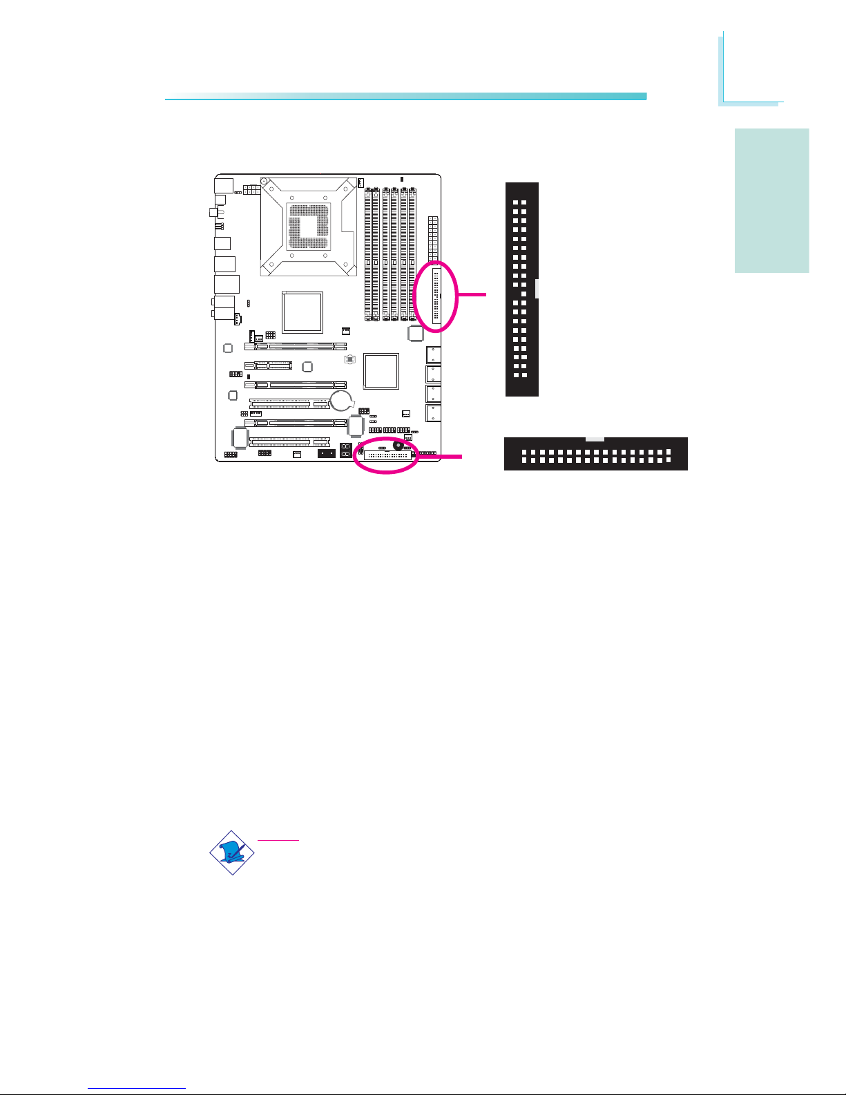
40
39
21
IDE
X
Floppy Disk Drive Connector and IDE Connector
Floppy Disk Drive Connector
The floppy disk drive connector is used to connect a floppy drive.
Insert one end of the floppy cable into this connector and the other
end-most connector to the floppy drive. The colored edge of the
cable should align with pin 1 of this connector.
IDE Disk Drive Connector
The IDE disk drive connector is used to connect 2 IDE disk drives.
An IDE cable have 3 connectors on them, one that plugs into this
connector and the other 2 connects to IDE devices. The connector
at the end of the cable is for the Master drive and the connector in
the middle of the cable is for the Slave drive. The colored edge of
the cable should align with pin 1 of this connector.
Note:
When using two IDE drives, one must be set as the master
and the other as the slave. Follow the instructions provided by
the drive manufacturer for setting the jumpers and/or switches
on the drives.
X
FDD
34
33
1
2
Page 22
E
22
English
English
1
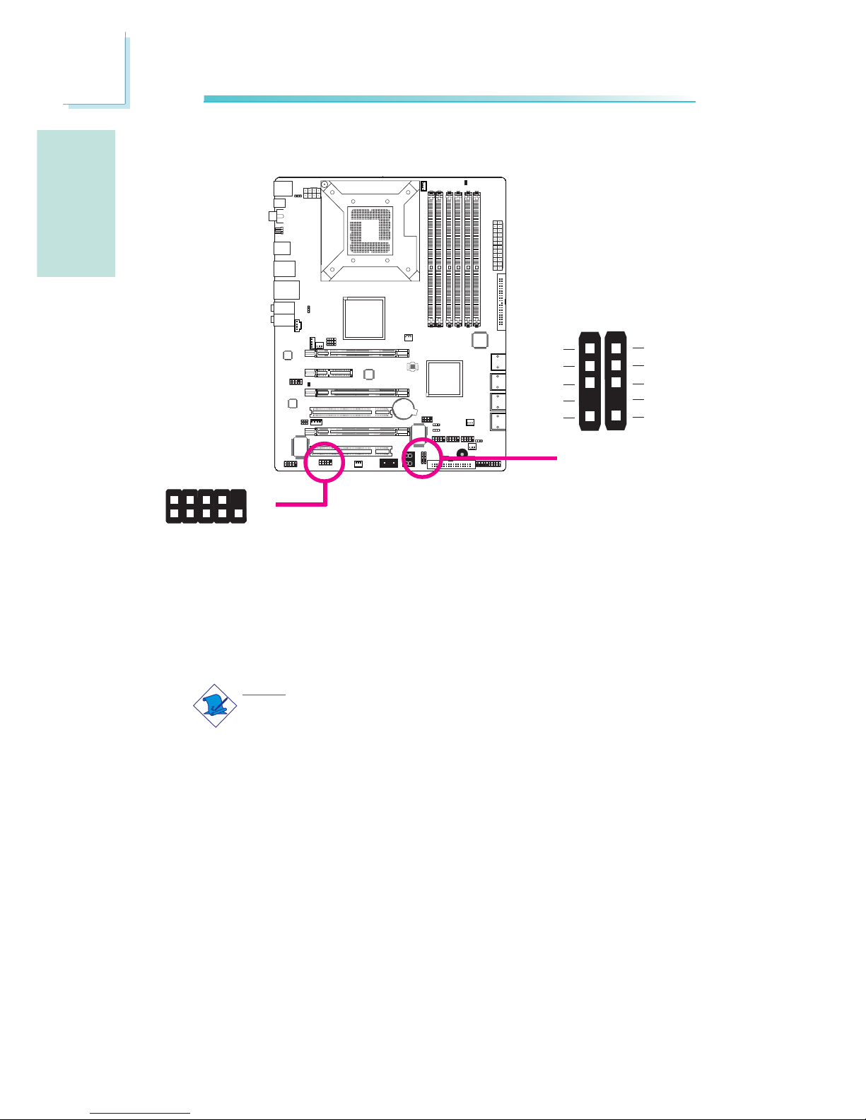
IrDA, CIR and Serial (COM) Connectors
IrDA and CIR Connectors
These connectors are used to connect an IrDA module and/or CIR
module.
Note:
The sequence of the pin functions on some IrDA/CIR cable
may be reversed from the pin function defined on the system
board. Make sure to connect the cable connector to the IrDA/
CIR connector according to their pin functions.
You may need to install the proper drivers in your operating system
to use the IrDA/CIR function. Refer to your operating system’s
manual or documentation for more information.
Serial (COM) Connector
The serial (COM) connector is used to connect modems, serial
printers, remote display terminals, or other serial devices. Your COM
port may come mounted on a card-edge bracket. Install the cardedge bracket to an available slot at the rear of the system chassis
then connect the serial port cable to this connector. The colored
edge of the cable should align with pin 1 of this connector.
X
1
9
2
CD
TD
RD
DTR
GND
RTS
DSR
CTS
RI
COM
X
IrDA CIR
1
5
VCC
N. C.
IRRX
Ground
IRTX
1
5
5VSB
N. C.
CIRRX
Ground
CIRTX
Page 23
E
23
English
English
1
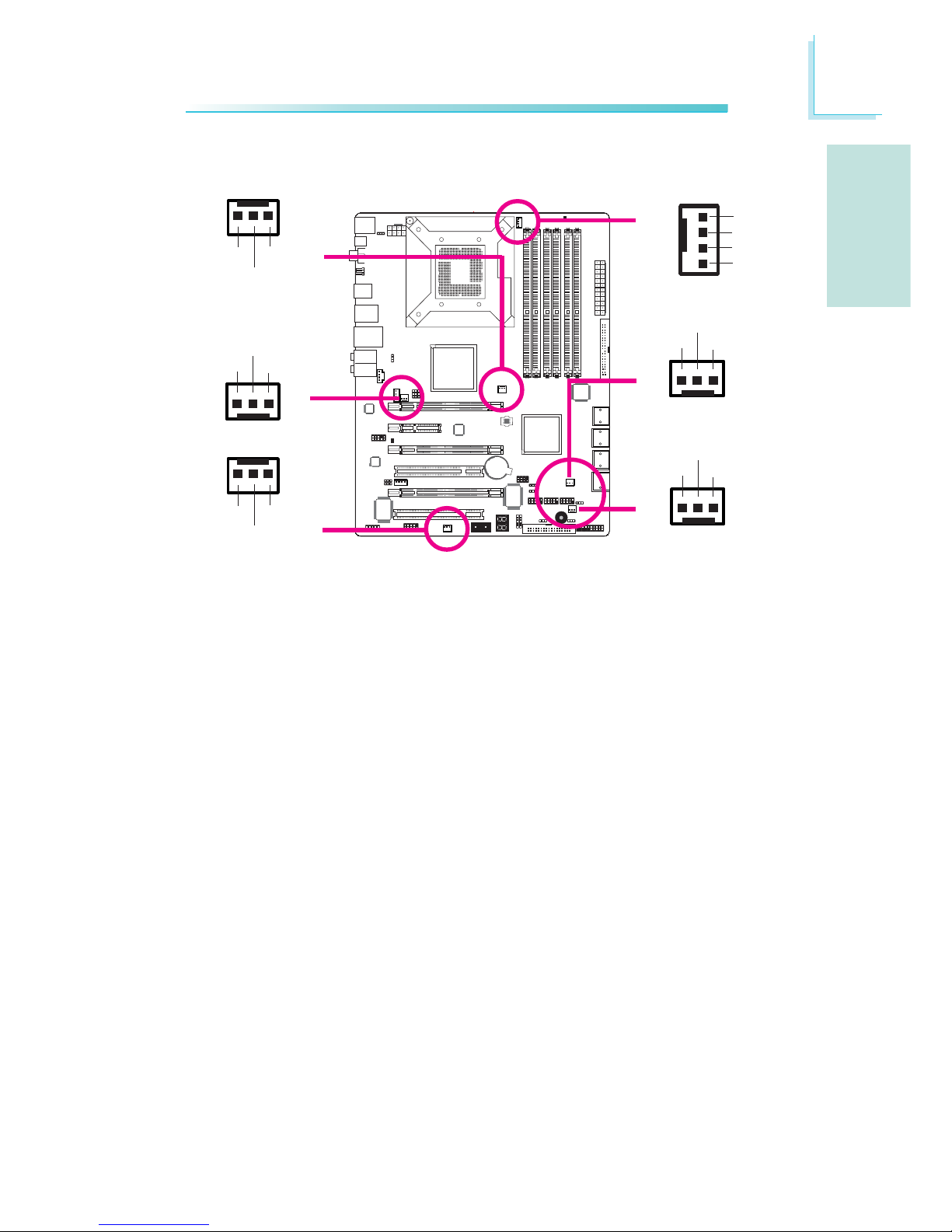
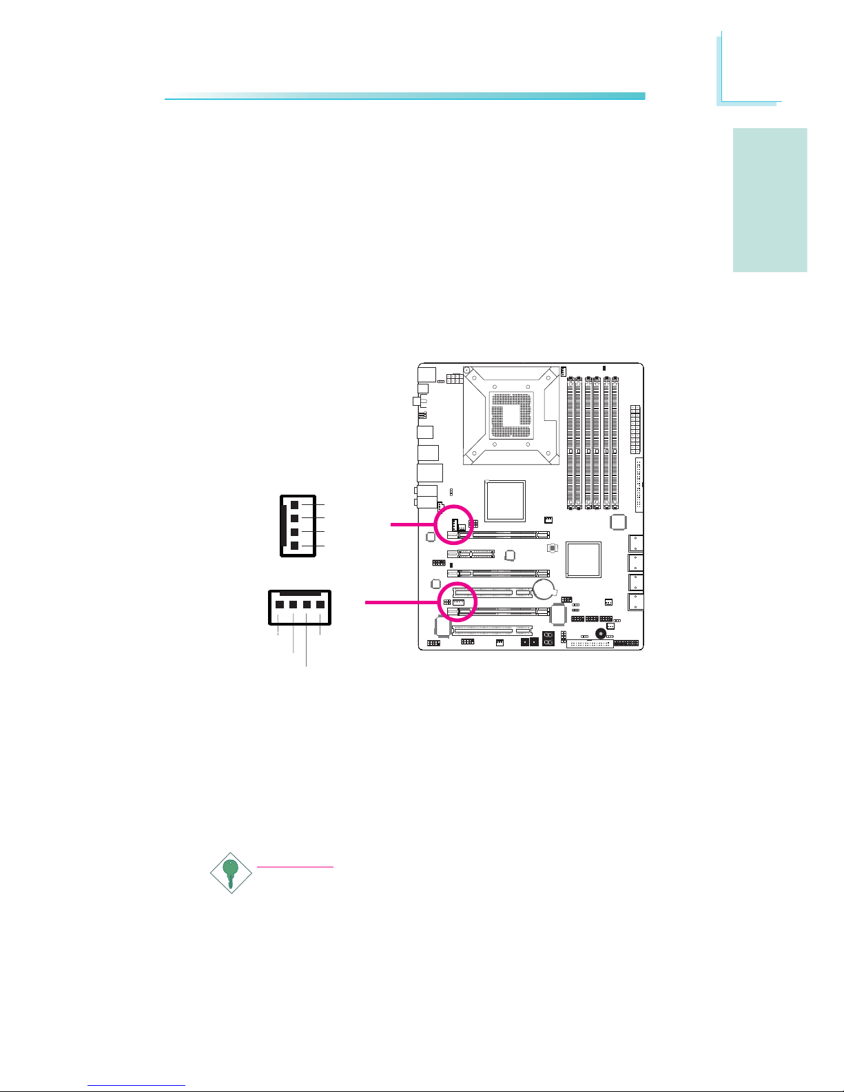
Cooling Fan Connectors
These fan connectors are used to connect cooling fans. Cooling fans
will provide adequate airflow throughout the chassis to prevent overheating the CPU and system board components.
X
X
CPU fan
Fan 2
System fan
X
NB fan
Fan 1
13
Ground
Power
N. C.
X
X
X
Sense
Power
Ground
Speed
Control
1
4
13
Ground
Power
N. C.
13
Ground
Power
N. C.
Fan 3
31
Ground
Power
N. C.
31
Ground
Power
N. C.
Page 24
E
24
English
English
1
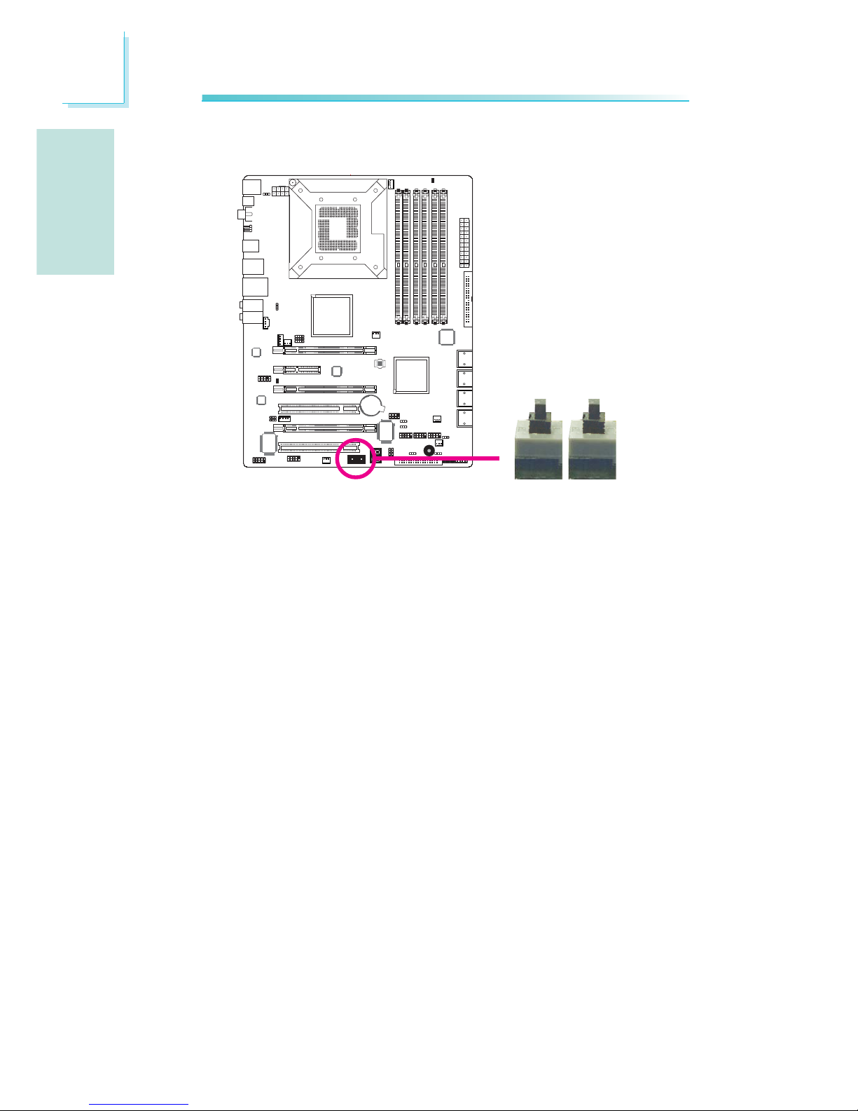
EZ Touch Switches
The presence of the power switch and reset switch on the system
board are user-friendly especially to DIY users. They provide convenience in powering on and/or resetting the system while fine tuning
the system board before it is installed into the system chassis.
X
Reset Power
Page 25
E
25
English
English
1
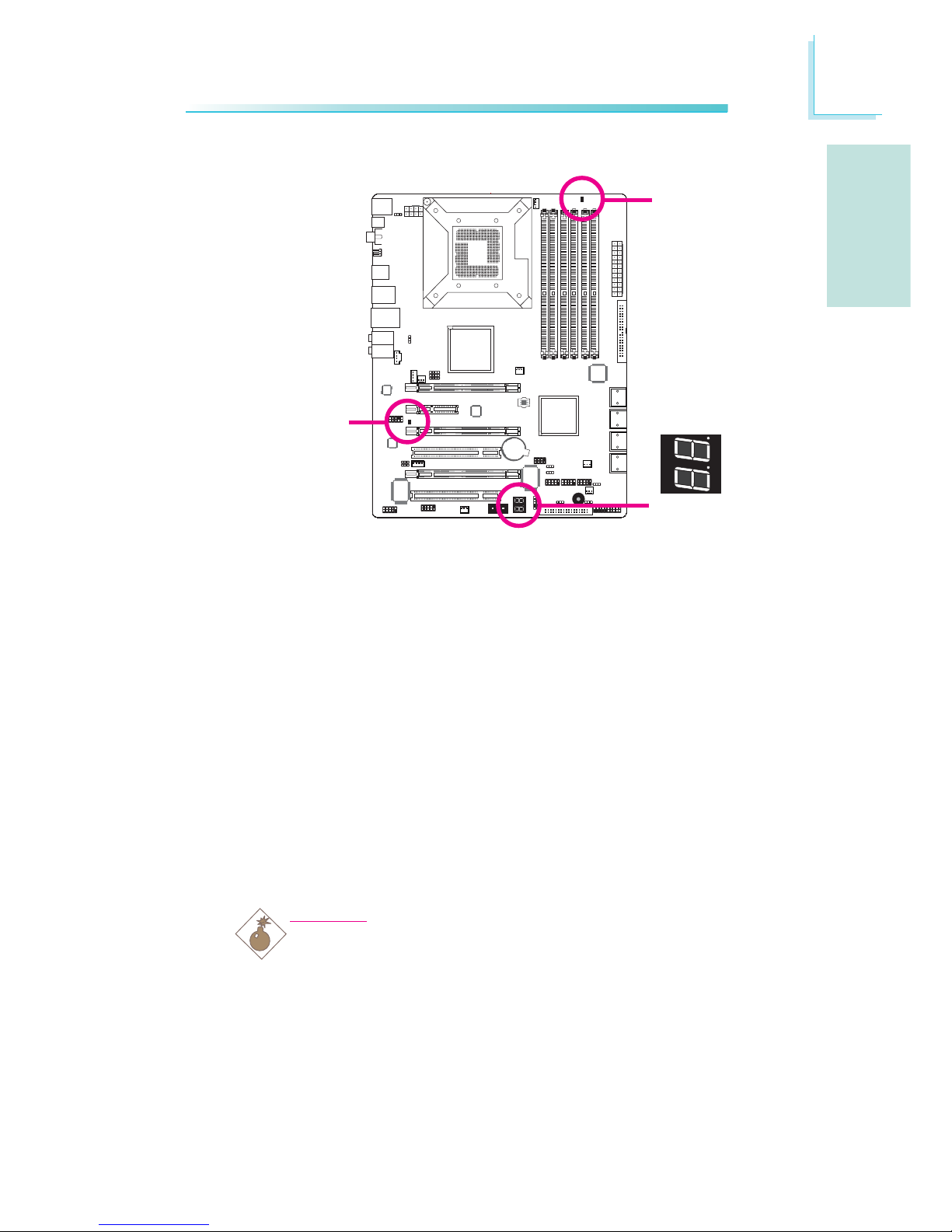
LEDs
DRAM Power LED
This LED will light when the system’s power is on.
Standby Power LED
This LED will light when the system is in the standby mode.
Diagnostic LED
The Diagnostic LED displays POST codes. POST (Power-On Self
Tests) which is controlled by the BIOS is performed whenever you
power-on the system. POST will detect the status of the system and
its components. Each code displayed on the LED corresponds to a
certain system status.
Warning:
When the DRAM Power LED and/or Standby Power LED lit red,
it indicates that power is present on the DIMM sockets and/or
PCI slots. Power-off the PC then unplug the power cord prior to
installing any memory modules or add-in cards. Failure to do so
will cause severe damage to the motherboard and components.
.
.
.
.
.
.
.
.
DRAM
Power LED
Standby
Power LED
Diagnostic
LED
Page 26
E
26
English
English
1
1
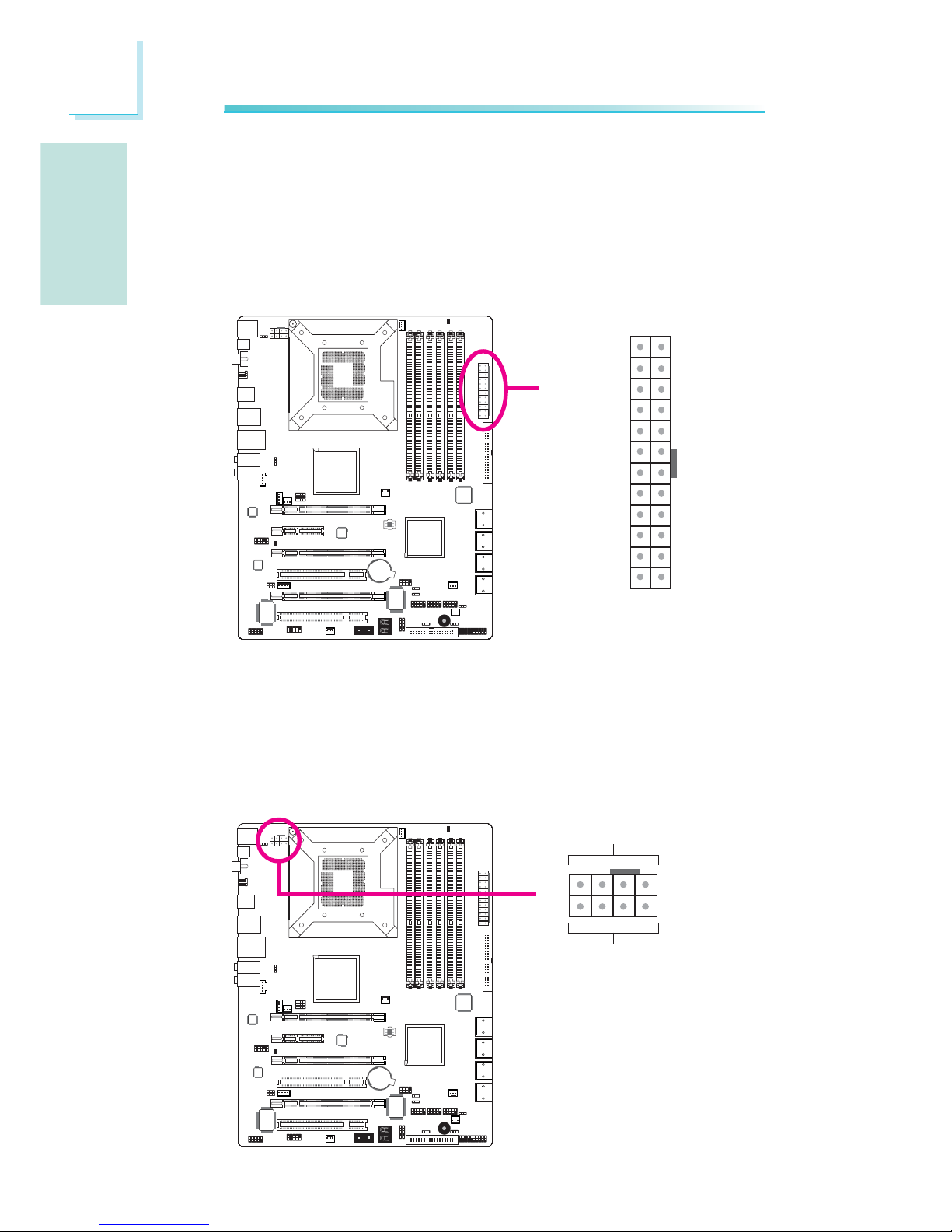
Power Connectors
Use a power supply that complies with the ATX12V Power Supply
Design Guide Version 1.1. An ATX12V power supply unit has a
standard 24-pin ATX main power connector that must be inserted
into this connector.
Your power supply unit may come with an 8-pin or 4-pin +12V
power connector. The +12V power enables the delivery of more
+12VDC current to the processor’s Voltage Regulator Module
(VRM). If available, it is preferable to use the 8-pin power; otherwise
connect a 4-pin power to this connector.
X
X
131
12 24
+3.3VDC
+3.3VDC
COM
+5VDC
COM
+5VDC
COM
PWR_OK
+5VSB
+12VDC
+12VDC
+3.3VDC
+3.3VDC
-12VDC
COM
PS_ON#
COM
COM
COM
NC
+5VDC
+5VDC
+5VDC
COM
+12V
Ground
14
58
Page 27
E
27
English
English
1
The FDD-type power connectors are additional power connector.s If
you are using more than one graphics cards, we recommend that
you plug power cables from your power supply unit to the 5V/12V
power connectors. This will provide more stability to the entire
system. The system board will still work even if the additional power
connector is not connected.
The system board requires a minimum of 300 Watt power supply
to operate. Your system configuration (CPU power, amount of
memory, add-in cards, peripherals, etc.) may exceed the minimum
power requirement. To ensure that adequate power is provided, we
strongly recommend that you use a minimum of 400 Watt (or
greater) power supply.
Important:
Insufficient power supplied to the system may result in instability or the add-in boards and peripherals not functioning
properly. Calculating the system’s approximate power usage is
important to ensure that the power supply meets the system’s
consumption requirements.
1
4
+5V
+12V
Ground
Ground
The power connectors from the power supply unit are designed to
fit the 24-pin and 8-pin connectors in only one orientation. Make
sure to find the proper orientation before plugging the connectors.
W
4
1
+12V
+5V
Ground
Ground
W
Page 28

E
28
English
English
Restarting the PC
Normally, you can power-off the PC by:
1. Pressing the power button at the front panel of the chassis.
or
2. Pressing the power switch that is on the system board (note: not
all system boards come with this switch).
If for some reasons you need to totally cut off the power supplied
to the PC, switch off the power supply or unplug the power cord.
Take note though that if you intend to restart it at once, please
strictly follow the steps below.
1. The time where power is totally discharged varies among power
supplies. It's discharge time is highly dependent on the system's
configuration such as the wattage of the power supply, the sequence of the supplied power as well as the number of peripheral devices connected to the system. Due to this reason, we
strongly recommend that you wait for the Standby Power LED
(refer to the “LEDs” section in this chapter for the location of the
Standby Power LED) to lit off.
2. After the Standby Power LED has lit off, wait for 6 seconds
before powering on the PC.
If the system board is already enclosed in a chassis which apparently will not make the Standby Power LED visible, wait for 15
seconds before you restore power connections. 15 seconds is
approximately the time that will take the LED to lit off and the
time needed before restoring power.
The above will ensure protection and prevent damage to the
motherboard and components.
Page 29
E
29
English
English
1
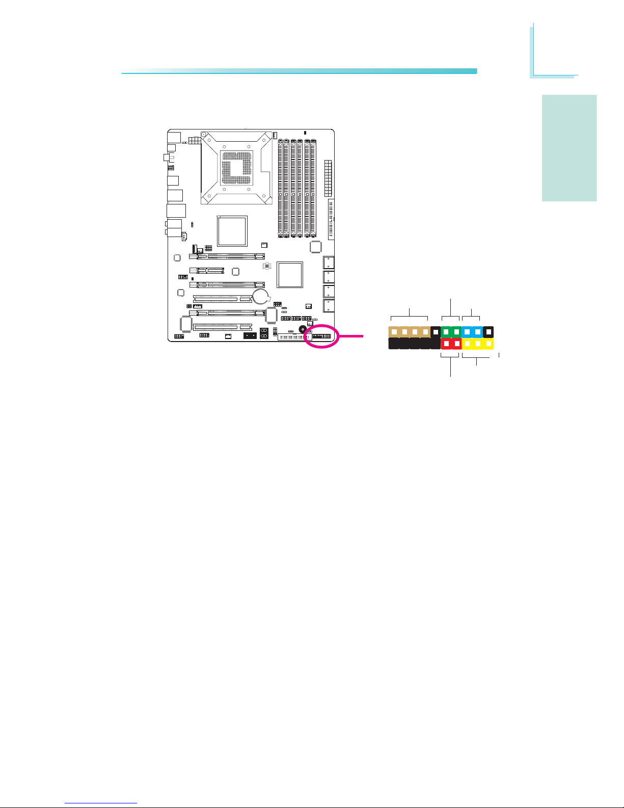
Front Panel Connectors
HD-LED: Primary/Secondary IDE LED
This LED will light when the hard drive is being accessed.
RESET: Reset Switch
This switch allows you to reboot without having to power off the
system thus prolonging the life of the power supply or system.
SPEAKER: Speaker Connector
This connects to the speaker installed in the system chassis.
ATX-SW: ATX Power Switch
Depending on the setting in the BIOS setup, this switch is a “dual
function power button” that will allow your system to enter the SoftOff or Suspend mode.
PWR-LED: Power/Standby LED
When the system’s power is on, this LED will light. When the system
is in the S1 (POS - Power On Suspend) or S3 (STR - Suspend To
RAM) state, it will blink every second.
X
1
2
19
20
HD-LED
RESET
SPEAKER
PWR-LED
ATX-SW
Page 30
E
30
English
English
1
Pin
3
5
14
16
8
10
18
20
7
9
13
15
17
19
2
4
6
HD-LED
(Primary/Secondary IDE LED)
Reserved
ATX-SW
(ATX power switch)
Reserved
RESET
(Reset switch)
SPEAKER
(Speaker connector)
PWR-LED
(Power/Standby LED)
Pin Assignment
HDD LED Power
HDD
N. C.
N. C.
PWRBT+
PWRBT-
N. C.
N. C.
Ground
H/W Reset
Speaker Data
N. C.
Ground
Speaker Power
LED Power (+)
LED Power (+)
LED Power (-) or Standby Signal
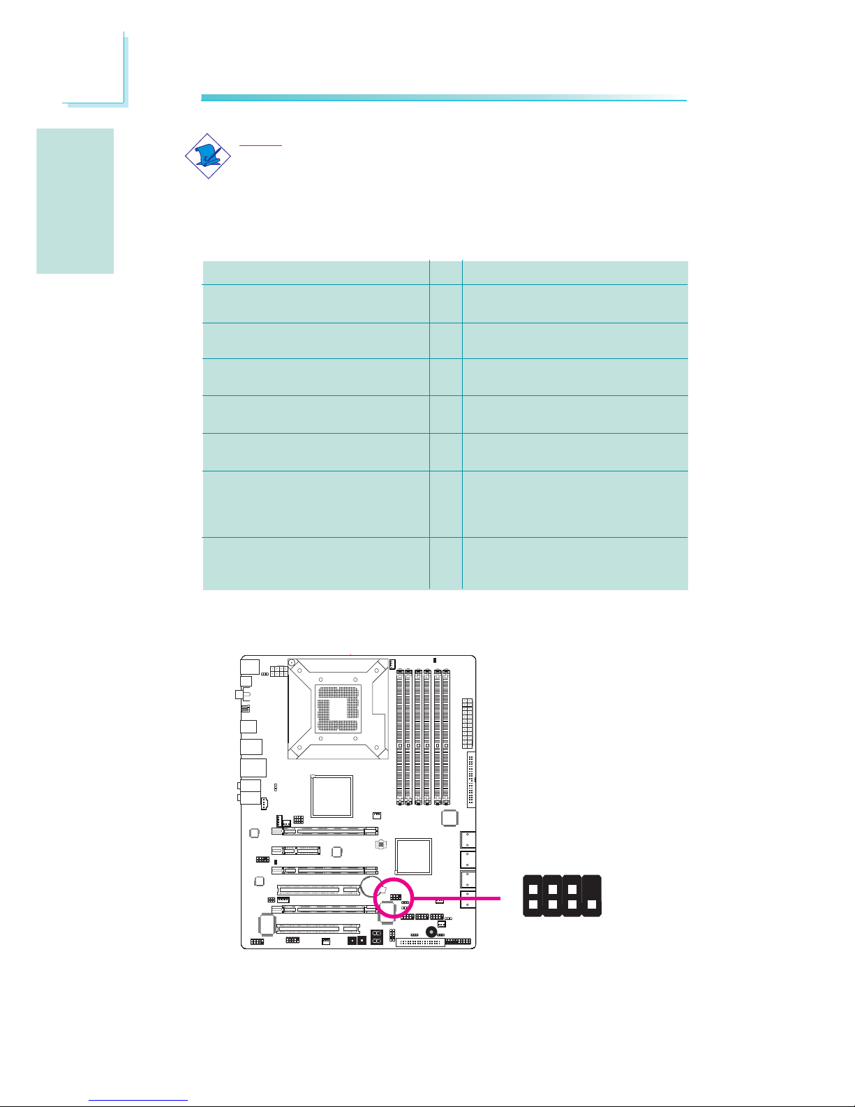
Download Flash BIOS Connector
1
GROUND
2
8
7
SPI_VCC3
SPI_CS0B
SPI_MIS0
SPI_HOLD#
SPI_CLK
SPI_MOSI
Note:
If a system did not boot-up and the Power/Standby LED did
not light after it was powered-on, it may indicate that the CPU
or memory module was not installed properly. Please make
sure they are properly inserted into their corresponding socket.
X
Page 31

E
31
English
English
1
PCI Express Slots
PCI Express x16
Install PCI Express x16 graphics card, that comply to the PCI Express specifications, into the PCI Express x16 slot. To install a graphics card into the x16 slot, align the graphics card above the slot
then press it down firmly until it is completely seated in the slot. The
retaining clip of the slot will automatically hold the graphics card in
place.
PCI Express x4
Install PCI Express cards such as network cards or other cards that
comply to the PCI Express specifications into the PCI Express x4
slot (PCIE 2).
PCIE 1
PCIE 2
PCIE 4
PCIE 3
Page 32

E
32
English
English
Smart Connectors
The Smart Connectors (USB, IEEE 1394 and Front Panel) serve as
extended connectors allowing you to easily connect cables to the
connectors that are on the system board. This is specially advantageous
when using the front panel connectors as this will prevent wrong cable
connection.
1. Connect all front panel cables
from the chassis to the front
panel smart connector. Connect
according to the pin definition
shown on the smart connector.
Front Panel Connectors
USB 1394 Front Panel
2. Connect the front panel smart
connector to the front panel
connector on the system board.
USB and IEEE 1394 Connectors
1. Connect your USB/1394 port cable to the USB/1394 smar t
connector. Connect according to the pin definition shown on the smart
connector.
2. Connect the USB/1394 smart connector to the respective connectors
on the system board.
Page 33

E
33
English
English
The Intel ICH10R chip alows configuring RAID on Serial ATA drives
connected to SATA 1 to SATA 6. It suppor ts RAID 0, RAID 1,
RAID 0+1 and RAID 5.
The JMicron JMB363 chip allows configuring RAID on another 2 Serial ATA drives connected to SATA 7 and SATA 8. It supports
RAID 0 and RAID 1.
RAID Levels
RAID 0 (Striped Disk Array without Fault Tolerance)
RAID 0 uses two new identical hard disk drives to read and write
data in parallel, interleaved stacks. Data is divided into stripes and
each stripe is written alternately between two disk drives. This improves the I/O performance of the drives at different channel; however it is not fault tolerant. A failed disk will result in data loss in the
disk array.
RAID 1 (Mirroring Disk Array with Fault Tolerance)
RAID 1 copies and maintains an identical image of the data from
one drive to the other drive. If a drive fails to function, the disk
array management software directs all applications to the other drive
since it contains a complete copy of the drive’s data. This enhances
data protection and increases fault tolerance to the entire system.
Use two new drives or an existing drive and a new drive but the
size of the new drive must be the same or larger than the existing
drive.
RAID 0+1 (Striping and Mirroring)
RAID 0+1 is a combination of data striping and data mirroring
providing the benefits of both RAID 0 and RAID 1. Use four new
drives or an existing drive and three new drives for this
configuration.
RAID 5
RAID 5 stripes data and parity information across hard drives. It is
fault tolerant and provides better hard drive performance and more
storage capacity.
Chapter 3 - RAID
Page 34

E
34
English
English
Settings
To enable the RAID function, the following settings are required.
1. Connect the Serial ATA drives.
2. Configure Serial ATA in the Award BIOS.
3. Configure RAID in the RAID BIOS.
4. Install the RAID driver during OS installation.
5. Install the Intel Matrix Storage Manager
6. Install the JMB36X Driver
Step 1: Connect the Serial ATA Drives
Refer to chapter 2 for details on connecting the Serial ATA drives.
Important:
1. Make sure you have installed the Serial ATA drives and connected the data
cables otherwise you won’t be able to enter the RAID BIOS utility.
2. Treat the cables with extreme caution especially while creating RAID. A damaged cable will ruin the entire installation process and operating system. The
system will not boot and you will lost all data in the hard drives. Please give
special attention to this warning because there is no way of recovering back
the data.
Step 2: Configure Serial ATA in the Award BIOS
1. Power-on the system then press <Del> to enter the main menu
of the Award BIOS.
2. Configure Serial ATA in the appropriate fields.
3. Press <Esc> to return to the main menu of the BIOS setup
utility. Select “Save & Exit Setup” then press <Enter>.
4. Type <Y> and press <Enter>.
5. Reboot the system.
tep 3: Configure RAID in the RAID BIOS
Configure RAID in the Intel RAID BIOS
When the system powers-up and all drives have been detected, the
Intel RAID BIOS status message screen will appear. Press the
<Ctrl> and <I> keys simultaneously to enter the utility. The utility
allows you to build a RAID system on Serial ATA drives.
Page 35

E
35
English
English
Configure RAID in the JMicron RAID BIOS
When the system powers-up and all hard disk drives have been
detected, the JMicron RAID BIOS status message screen will appear.
Press the <Ctrl> and <J> keys simultaneously to enter the utility.
The utility allows you to build a RAID system on Serial ATA drives.
Step 4: Install the RAID Driver During OS Installation
The RAID driver must be installed during the Windows® XP or
Windows® 2000 installation using the F6 installation method. This is
required in order to install the operating system onto a hard drive
or RAID volume when in RAID mode or onto a hard drive when in
AHCI mode.
1. Start Windows Setup by booting from the installation CD.
2. Press <F6> when prompted in the status line with the ‘Press
F6 if you need to install a third party SCSI or RAID driver’
message.
3. Press <S> to “Specify Additional Device”.
4. At this point you will be prompted to insert a floppy disk
containing the RAID driver. Insert the provided RAID driver
diskette.
5. Locate for the drive where you inserted the diskette then select
RAID or AHCI controller that corresponds to your BIOS setup.
Press <Enter> to confirm.
You have successfully installed the driver. However you must continue
installing the OS. Leave the floppy disk in the floppy drive until the
system reboots itself because Windows setup will need to copy the
files again from the floppy disk to the Windows installation folders.
After Windows setup has copied these files again, remove the floppy
diskette so that Windows setup can reboot as needed.
Step 5: Install the Intel Matrix Storage Manager
Step 6: Install the JMB36X Driver
For steps 5 and 6, refer to the complete version of the manual for
steps on installing the utlity and driver. Please download the manual
from DFI’s website. Visit www.dfi.com.
Page 36

36
®
®
®
®
Page 37

37
Page 38

38
Page 39

39
1
X
JP2
312 312
JP10
X
1
3
2
1
3
2
Page 40

40
1-2 On: 5V
2-3 On:
5VSB
2-3 On:
5VSB
1
X
JP7
2-3 On:
5VSB
31
2
312
1
X
USB 6-11
(JP5)
X
USB 0-5
(JP6)
1
3
2
1
3
2
312 312
Page 41

41
1
JP8
312
312
X
Page 42

42
1
312 312
X
JP1
Page 43

43
1
312
312
X
JP12
Page 44

44
4
1
X
JP15
132
JP14
JP13
Page 45

45
1
X
312
312
31
2
312
1-2 On 2-3 On
1-2 On 2-3 On
JP26
JP27
CPU_VTT
1.2V (default)
1.4V
1.6V
JP26
1-2 On
2-3 On
2-3 On
JP27
1-2 On
2-3 On
1-2 On
USB 8-9
USB 10-11
Mic-in
Side R/L
Rear R/L
Line-in
Front R/L
LAN
USB 6-7
S/PDIF-out
Clear CMOS
1394-0
Page 46

46
1
W
1394-0
W
1394-1
W
1
2
10
9
Page 47

47
1
LAN
W
W
W
USB 11
USB 10
USB 9
USB 8
1
VCC
-Data
+Data
GND
Key
VCC
-Data
+Data
GND
N. C.
2
10
9
USB 4-5
USB 2-3
USB 0-1
USB 7
USB 6
Page 48

48
1
W
W
Front R/L
Line-in
Mic-in
Rear R/L
Center/
Subwoofer
Side R/L
1
2
10
Mic-L
Mic-R
Line-out-R
Front-sense
Line-out-L
GND
Presense-signal
Mic-jack-sense
Key
Line-out-jack-sense
9
4
1
Left audio channel
Right audio channel
Ground
Ground
W
Page 49

49
Page 50

50
1
SATA 1-2
SATA 7-8
SATA 5-6
SATA 3-4
Page 51

51
1
40
39
21
IDE
X
X
FDD
34
33
1
2
Page 52

52
1
X
1
9
2
CD
TD
RD
DTR
GND
RTS
DSR
CTS
RI
COM
X
IrDA CIR
1
5
VCC
N. C.
IRRX
Ground
IRTX
1
5
5VSB
N. C.
CIRRX
Ground
CIRTX
Page 53

53
1
Power
X
Reset
1
X
X
CPU fan
2nd fan
System fan
X
NB fan
1st fan
13
Ground
Power
N. C.
X
X
X
Sense
Power
Ground
Speed
Control
1
4
13
Ground
Power
N. C.
13
Ground
Power
N. C.
Fan 3
31
Ground
Power
N. C.
31
Ground
Power
N. C.
Page 54

54
.
.
.
.
.
.
.
.
1
DRAM
Power LED
Standby
Power LED
Diagnostic
LED
Page 55

55
1
X
131
12 24
+3.3VDC
+3.3VDC
COM
+5VDC
COM
+5VDC
COM
PWR_OK
+5VSB
+12VDC
+12VDC
+3.3VDC
+3.3VDC
-12VDC
COM
PS_ON#
COM
COM
COM
NC
+5VDC
+5VDC
+5VDC
COM
1
X
+12V
Ground
14
58
Page 56

56
1
1
4
+5V
+12V
Ground
Ground
W
4
1
+12V
+5V
Ground
Ground
W
Page 57

57
Page 58

58
1
X
1
2
19
20
HD-LED
RESET
SPEAKER
PWR-LED
ATX-SW
Page 59

59
1
1
GROUND
2
8
7
SPI_VCC3
SPI_CS0B
SPI_MIS0
SPI_HOLD#
SPI_CLK
SPI_MOSI
X
Page 60

60
1
PCIE 2
PCIE 3
PCIE 4
PCIE 1
Page 61

61
USB 1394 Front Panel
Page 62

62
Page 63

63
Page 64

64
® ®
Page 65

65
Page 66

66
®
®
®
Page 67

67
Page 68

68
Page 69

69
1
X
JP2
312 312
JP10
X
1
3
2
1
3
2
Page 70

70
2-3 On:
5VSB
2-3 On:
5VSB
1
X
JP7
2-3 On:
5VSB
31
2
312
1
X
USB 6-11
(JP5)
X
USB 0-5
(JP6)
1
3
2
1
3
2
312 312
Page 71

71
•
•
1
JP8
312 312
X
Page 72

72
1
312 312
X
JP1
Page 73

73
1
312
312
X
JP12
Page 74

74
4
1
X
JP15
132
JP14
JP13
Page 75

75
1
X
312
312
31
2
312
1-2 On 2-3 On
1-2 On 2-3 On
JP26
JP27
CPU_VTT
1.2V (default)
1.4V
1.6V
JP26
1-2 On
2-3 On
2-3 On
JP27
1-2 On
2-3 On
1-2 On
USB 8-9
USB 10-11
Mic-in
Side R/L
Rear R/L
Line-in
Front R/L
LAN
USB 6-7
1394-0
Page 76

76
1
W
1394-0
W
1394-1
W
1
2
10
9
Page 77

77
1
LAN
W
W
W
USB 11
USB 10
USB 9
USB 8
1
VCC
-Data
+Data
GND
Key
VCC
-Data
+Data
GND
N. C.
2
10
9
USB 4-5
USB 2-3
USB 0-1
USB 7
USB 6
Page 78

78
1
W
W
Front R/L
Line-in
Mic-in
Rear R/L
Center/
Subwoofer
Side R/L
1
2
10
Mic-L
Mic-R
Line-out-R
Front-sense
Line-out-L
GND
Presense-signal
Mic-jack-sense
Key
Line-out-jack-sense
9
4
1
Left audio channel
Right audio channel
Ground
Ground
W
CD-in
Page 79

79
Page 80

80
1
SATA 1-2
SATA 7-8
SATA 5-6
SATA 3-4
Page 81

81
1
40
39
21
IDE
X
X
FDD
34
33
1
2
Page 82

82
1
X
1
9
2
CD
TD
RD
DTR
GND
RTS
DSR
CTS
RI
COM
X
IrDA C IR
1
5
VCC
N. C.
IRRX
Ground
IRTX
1
5
5VSB
N. C.
CIRRX
Ground
CIRTX
Page 83

83
1
Power
X
Reset
1
X
X
CPU fan
2nd fan
System fan
X
NB fan
1st fan
13
Ground
Power
N. C.
X
X
X
Sense
Power
Ground
Speed
Control
1
4
13
Ground
Power
N. C.
13
Ground
Power
N. C.
Fan 3
31
Ground
Power
N. C.
31
Ground
Power
N. C.
Page 84

84
.
.
.
.
.
.
.
.
1
DRAM
Power LED
Standby
Power LED
Diagnostic
LED
Page 85

85
1
X
131
12 24
+3.3VDC
+3.3VDC
COM
+5VDC
COM
+5VDC
COM
PWR_OK
+5VSB
+12VDC
+12VDC
+3.3VDC
+3.3VDC
-12VDC
COM
PS_ON#
COM
COM
COM
NC
+5VDC
+5VDC
+5VDC
COM
1
X
+12V
Ground
14
58
Page 86

86
1
1
4
+5V
+12V
Ground
Ground
W
4
1
+12V
+5V
Ground
Ground
W
Page 87

87
Page 88

88
1
X
1
2
19
20
HD-LED
RESET
SPEAKER
PWR-LED
ATX-SW
Page 89

89
1
1
GROUND
2
8
7
SPI_VCC3
SPI_CS0B
SPI_MIS0
SPI_HOLD#
SPI_CLK
SPI_MOSI
X
Page 90

90
1
PCIE 1
PCIE 2
PCIE 4
PCIE 3
Page 91

91
USB 1394 Front Panel
Page 92

92
Page 93

93
Page 94

94
®
®
Page 95

95
®
®
®
®
®
Page 96

96
Page 97

97
1
X
JP2
312 312
JP10
X
1
3
2
1
3
2
Page 98

98
Page 99

99
1
X
JP7
31
2
312
1-2 On: 5V
2-3 On:
5VSB
Page 100

100
1-2 On: 5V
1-2 On: 5V
2-3 On:
5VSB
2-3 On:
5VSB
1
X
USB 6-11
(JP5)
X
USB 0-5
(JP6)
1
3
2
1
3
2
312
312
 Loading...