

DFI KU968 User Manual
www.dfi .comChapter 1 Introduction
1
KU968
COM Express Compact Module
User’s Manual
A45600815

www.dfi .comChapter 1 Introduction
2
Copyright
This publication contains information that is protected by copyright. No part of it may be reproduced in any form or by any means or used to make any transformation/adaptation without
the prior written permission from the copyright holders.
This publication is provided for informational purposes only. The manufacturer makes no
representations or warranties with respect to the contents or use of this manual and specifically disclaims any express or implied warranties of merchantability or fitness for any particular
purpose. The user will assume the entire risk of the use or the results of the use of this document. Further, the manufacturer reserves the right to revise this publication and make changes
to its contents at any time, without obligation to notify any person or entity of such revisions
or changes.
Changes after the publication’s first release will be based on the product’s revision. The website
will always provide the most updated information.
© 2018. All Rights Reserved.
Trademarks
Product names or trademarks appearing in this manual are for identification purpose only and
are the properties of the respective owners.
COM Express Specification Reference
PICMG® COM Express ModuleTM Base Specification.
http://www.picmg.org/
FCC and DOC Statement on Class B
This equipment has been tested and found to comply with the limits for a Class B digital
device, pursuant to Part 15 of the FCC rules. These limits are designed to provide reasonable protection against harmful interference when the equipment is operated in a residential
installation. This equipment generates, uses and can radiate radio frequency energy and, if not
installed and used in accordance with the instruction manual, may cause harmful interference
to radio communications. However, there is no guarantee that interference will not occur in a
particular installation. If this equipment does cause harmful interference to radio or television
reception, which can be determined by turning the equipment off and on, the user is encouraged to try to correct the interference by one or more of the following measures:
• Reorient or relocate the receiving antenna.
• Increase the separation between the equipment and the receiver.
• Connect the equipment into an outlet on a circuit different from that to which the receiver
is connected.
• Consult the dealer or an experienced radio TV technician for help.
Notice:
1. The changes or modifications not expressly approved by the party responsible for compliance could void the user’s authority to operate the equipment.
2. Shielded interface cables must be used in order to comply with the emission limits.

www.dfi .comChapter 1 Introduction
3
Table of Contents
Copyright .............................................................................................................2
Trademarks ........................................................................................................2
COM Express Specification Reference ...................................................2
FCC and DOC Statement on Class B ..................................................... 2
Warranty ............................................................................................................4
Static Electricity Precautions ......................................................................4
Safety Measures ..............................................................................................4
About the Package .........................................................................................5
Optional Items..................................................................................................5
Before Using the System Board ...............................................................5
Chapter 1 - Introduction .............................................................................6
Specifications ................................................................................................6
Features ..........................................................................................................7
Chapter 2 - Concept .......................................................................8
COM Express Module Standards .............................................................. 8
Specification Comparison Table ...............................................................9
Chapter 3 - Hardware Installation .............................................. 10
Board Layout ...............................................................................................10
Block Diagram ............................................................................................. 10
System Memory .......................................................................................... 11
Connectors ...................................................................................................12
CPU Fan Connector .....................................................................................12
COM Express Connectors ............................................................................13
COM Express connectors Signal Discription .................................................. 14
Standby Power LED ................................................................................... 21
Cooling Option ............................................................................................21
Installing KU968 onto a Carrier Board ................................................22
Installing the COM Express Debug Card ............................................. 24

www.dfi .comChapter 1 Introduction
4
Warranty
1. Warranty does not cover damages or failures that arised from misuse of the product,
inability to use the product, unauthorized replacement or alteration of components and
product specifications.
2. The warranty is void if the product has been subjected to physical abuse, improper installation, modification, accidents or unauthorized repair of the product.
3. Unless otherwise instructed in this user’s manual, the user may not, under any circumstances, attempt to perform service, adjustments or repairs on the product, whether in or
out of warranty. It must be returned to the purchase point, factory or authorized service
agency for all such work.
4. We will not be liable for any indirect, special, incidental or consequencial damages to the
product that has been modified or altered.
Static Electricity Precautions
It is quite easy to inadvertently damage your PC, system board, components or devices even
before installing them in your system unit. Static electrical discharge can damage computer
components without causing any signs of physical damage. You must take extra care in handling them to ensure against electrostatic build-up.
1. To prevent electrostatic build-up, leave the system board in its anti-static bag until you are
ready to install it.
2. Wear an antistatic wrist strap.
3. Do all preparation work on a static-free surface.
4. Hold the device only by its edges. Be careful not to touch any of the components, contacts
or connections.
5. Avoid touching the pins or contacts on all modules and connectors. Hold modules or connectors by their ends.
Safety Measures
To avoid damage to the system:
• Use the correct AC input voltage range.
To reduce the risk of electric shock:
• Unplug the power cord before removing the system chassis cover for installation or servicing. After installation or servicing, cover the system chassis before plugging the power
cord.
Important:
Electrostatic discharge (ESD) can damage your processor, disk drive and other components. Perform the upgrade instruction procedures described at an ESD workstation only. If such a station is not available, you can provide some ESD protection by
wearing an antistatic wrist strap and attaching it to a metal part of the system chassis. If a wrist strap is unavailable, establish and maintain contact with the system
chassis throughout any procedures requiring ESD protection.

www.dfi .comChapter 1 Introduction
5
About the Package
The package contains the following items. If any of these items are missing or damaged,
please contact your dealer or sales representative for assistance.
• One KU968 board
• One heat sink (Height: 23.8mm)
Optional Items
• COM332-B carrier board kit
• Heat spreader (Height: 11mm)
The board and accessories in the package may not come similar to the information listed
above. This may differ in accordance with the sales region or models in which it was sold. For
more information about the standard package in your region, please contact your dealer or
sales representative.
Before Using the System Board
Before using the system board, prepare basic system components.
If you are installing the system board in a new system, you will need at least the following
internal components.
• Storage devices such as hard disk drive, etc.
You will also need external system peripherals you intend to use which will normally include at
least a keyboard, a mouse and a video display monitor.

www.dfi .comChapter 1 Introduction
6
Chapter 1 - Introduction
Specifications
Chapter 1
SYSTEM Processor 7th Generation Intel® CoreTM Processors, BGA 1356
Intel
®
CoreTM i7-7600U Processor, Dual Core, 4M Cache, 2.8GHz (3.9GHz), 15W
Intel
®
CoreTM i5-7300U Processor, Dual Core, 3M Cache, 2.6GHz (3.5GHz), 15W
Intel
®
CoreTM i3-7100U Processor, Dual Core, 3M Cache, 2.4GHz, 15W
Intel
®
Celeron® Processor 3965, Dual Core, 2M Cache, 2.2GHz, 15W
Memory 4GB/8GB DDR4 Memory Down
Dual Channel DDR4 2133MHz
BIOS Insyde SPI 128Mbit
GRAPHICS Controller Intel® HD Graphics
Feature OpenGL 5.0, DirectX 12, OpenCL 2.1
HW Decode: AVC/H.264, MPEG2, VC1/WMV9, JPEG/MJPEG, HEVC/H265, VP8, VP9
HW Encode: AVC/H.264, MPEG2, JPEG, HEVC/H265, VP8, VP9
Display 1 x VGA/DDI (DDI available upon request)
1 x LVDS/eDP (eDP available upon request)
1 x DDI
VGA: resolution up to 1920x1200 @ 60Hz
LVDS: dual channel 24-bit, resolution up to 1920x1200 @ 60Hz
eDP: resolution up to 4096x2304 @ 60Hz
HDMI: resolution up to 4096x2160 @ 30/24Hz
DP++: resolution up to 4096x2304 @ 60Hz
Triple Displays VGA + LVDS + DDI
DDI + eDP + DDI
EXPANSION Interface 5 PCIe x1 or 4 PCIe x1 + 1 PCIe x4 or 3 PCIe x1 + 2 PCIe x2 (support up to 5
devices and 8 lanes)
1 x LPC
1 x I
2
C
1 x SMBus
2 x UART (TX/RX)
AUDIO Interface HD Audio
ETHERNET Controller 1 x Intel® I219LM with iAMT11.0 PCIe (10/100/1000Mbps)
I/O USB 4 x USB 3.0
8 x USB 2.0
SATA 3 x SATA 3.0 (up to 6Gb/s)
RAID 0/1/5/10
DIO 1 x 8-bit DIO
WATCHDOG
TIMER
Output &
Interval
System Reset, Programmable via Software from 1 to 255 Seconds
SECURITY TPM Available Upon Request
POWER Type 12V, 5VSB, VCC_RTC (ATX mode)
12V, VCC_RTC (AT mode)
Consumption TBD
OS SUPPORT Windows: Windows 10 IoT Enterprise 64-bit
LINUX: Yocto Project v2.2
ENVIRONMENT Temperature Operating
: 0 to 60°C
: -45 to 85°C (with heat spreader)
Storage: -40 to 85°C
Humidity Operating: 5 to 90% RH
Storage: 5 to 90% RH
MTBF TBD
MECHANICAL Dimensions COM Express® Compact
95mm (3.74") x 95mm (3.74")
Compliance PICMG COM Express
®
R2.1, Type 6

www.dfi .comChapter 1 Introduction
7
Chapter 1
Features
• Watchdog Timer
The Watchdog Timer function allows your application to regularly “clear” the system at the set
time interval. If the system hangs or fails to function, it will reset at the set time interval so
that your system will continue to operate.
• DDR4
DDR4 delivers increased system bandwidth and improves performance. The advantages of
DDR4 provide an extended battery life and improve the performance at a lower power than
DDR3/DDR2.
• Graphics
The integrated Intel® HD graphics engine delivers an excellent blend of graphics performance
and features to meet business needs. It delivers enhanced media conversion rates and higher
frame rates on 4K Ultra HD videos. These enhancements deliver the performance and compatibility to meet the demand for business and home entertainment applications. Supports 1 x
VGA/DDI (DDI available upon request), 1 x LVDS/eDP ( eDP available upon request) and 1 x
DDI display interfaces.
• Serial ATA
Serial ATA is a storage interface that is compliant with SATA 1.0a specification. With speed of
up to 6Gb/s (SATA 3.0), it improves hard drive performance faster than the standard parallel
ATA whose data transfer rate is 100MB/s. The bandwidth of the SATA 3.0 will be limited by
carrier board design.
• Gigabit LAN
The Intel® I219LM Gigabit LAN PHY controller supports up to 1Gbps data transmission.
• USB
The system board supports the new USB 3.0. It is capable of running at a maximum transmission speed of up to 5 Gbit/s (625 MB/s) and is faster than USB 2.0 (480 Mbit/s, or 60 MB/s)
and USB 1.1 (12Mb/s). USB 3.0 reduces the time required for data transmission, reduces
power consumption, and is backward compatible with USB 2.0. It is a marked improvement in
device transfer speeds between your computer and a wide range of simultaneously accessible
external Plug and Play peripherals.
www.dfi .comChapter 2 Concept
8
Chapter 2
Chapter 2 - Concept
106.00
91.00
70.00
51.00
4.00
18.00
6.00
0.00
16.50
4.00
0.00
Extended
BasicCompact
Mini
74.20
80.00
91.00
121.00
151.00
Common for all Form Factors
Extended only
Basic only
Compact only
Compact and Basic only
Mini only
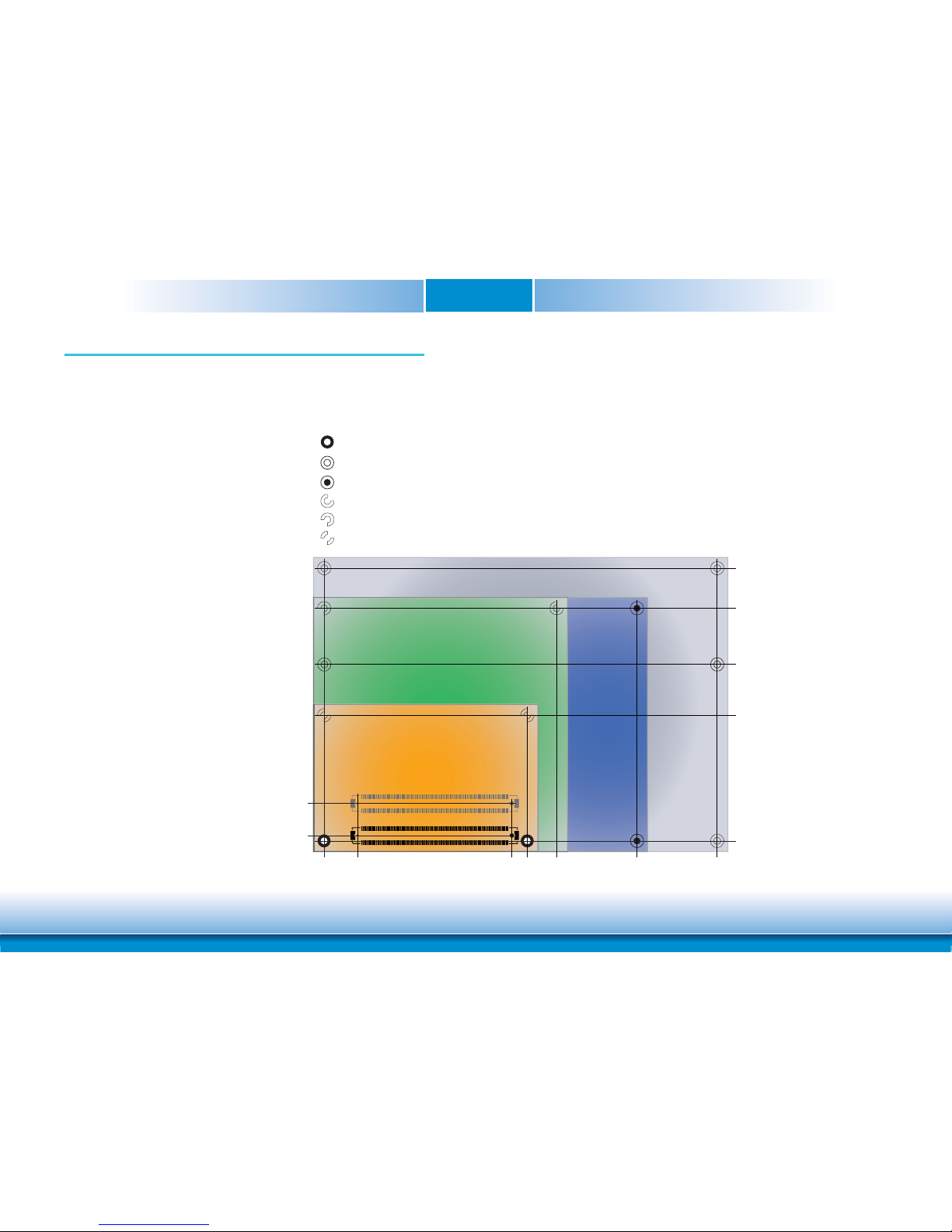
COM Express Module Standards
The figure below shows the dimensions of the different types of COM Express modules.
KU968 is a COM Express Compact module. The dimension is 95mm x 95mm.
 Loading...