

DFI KS190-KH, KS215-KH, KS150-KH Installation Manual
1
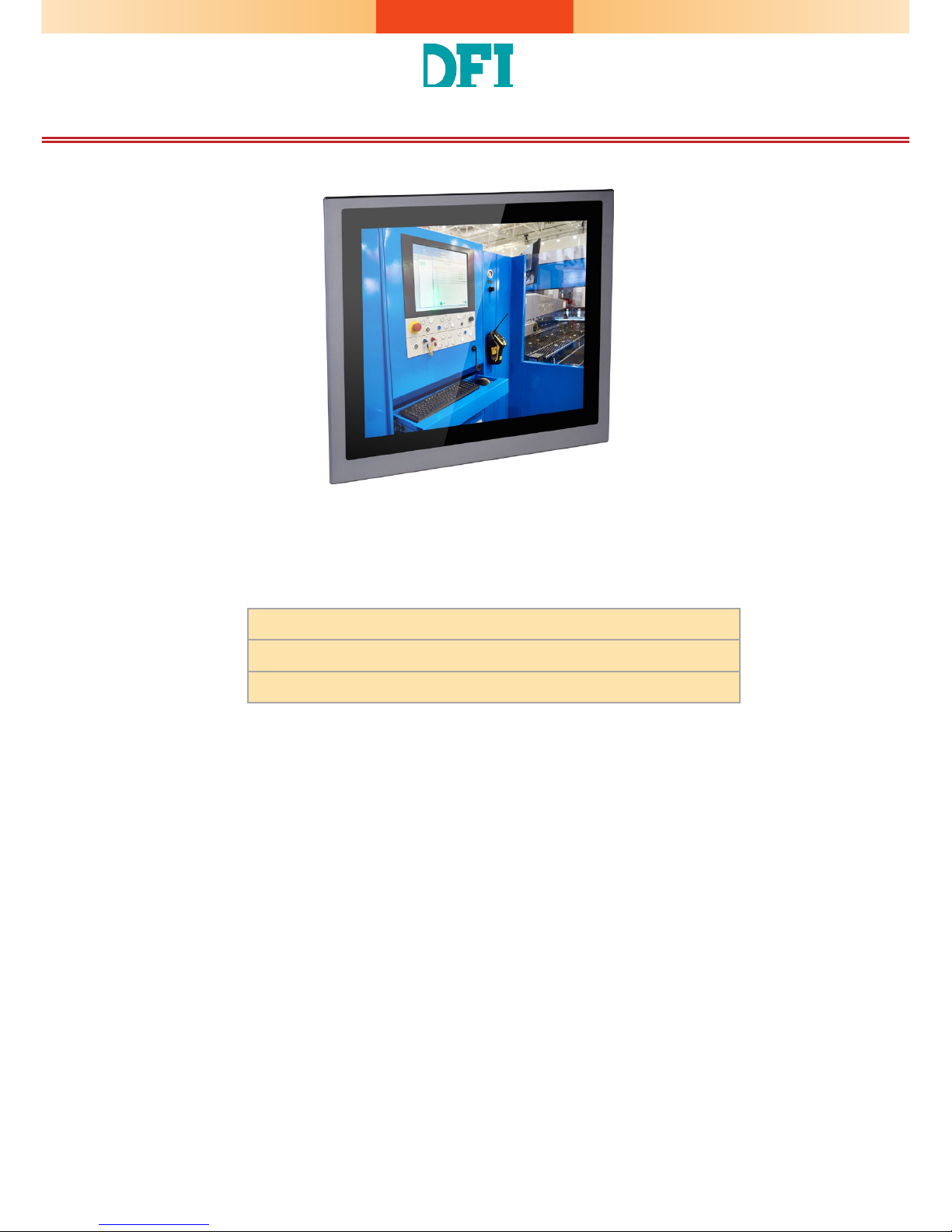
KS150/190/215-KH Installation Guide
Package Contents
•
One 15", 19", or 21.5" Modular Touch Panel PC
•
3-pin Terminal Blcok Connector
•
SATA, Mini PCIe and M.2 Installation Screws
DFI reserves the right to change the specications at any time prior to the
product's release. For the latest revision and more details of the installation
procedure, please refer to the user's manual on the website.
www.d.com
2
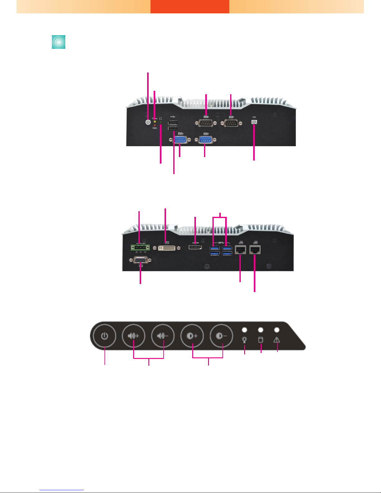
Panel
Front OSD Functions (only for models with front OSD)
Notes on OSD Settings:
The front OSD is capable of controlling the system in the following ways in addition to
its explicit functions.
1. System Power On/Off: Press the Backlight on/off button for 3 seconds.
2. Light Sensor On/Off: Press the Brightness up arrow for 3 seconds.
3. OSD Lock/Unlock: Press the Brightness down arrow for 3 seconds.
4. The Alarm LED has no funtion for the KS-KH Series.
Backlight or Power
on/off
Volume Brightness
Power HDD Alarm LED
Bottom View
Top View
COM 2
Power Button
Reset Button
COM 3
COM 4
Status LED (Orange)
HDD LED (Red)
COM 1
Extended Power
on/off Switch
USB 2.0
DC-in
USB 3.0
DVI-D
(DVI-I connector)
LAN 1
LAN 2
VGA
HDMI
3
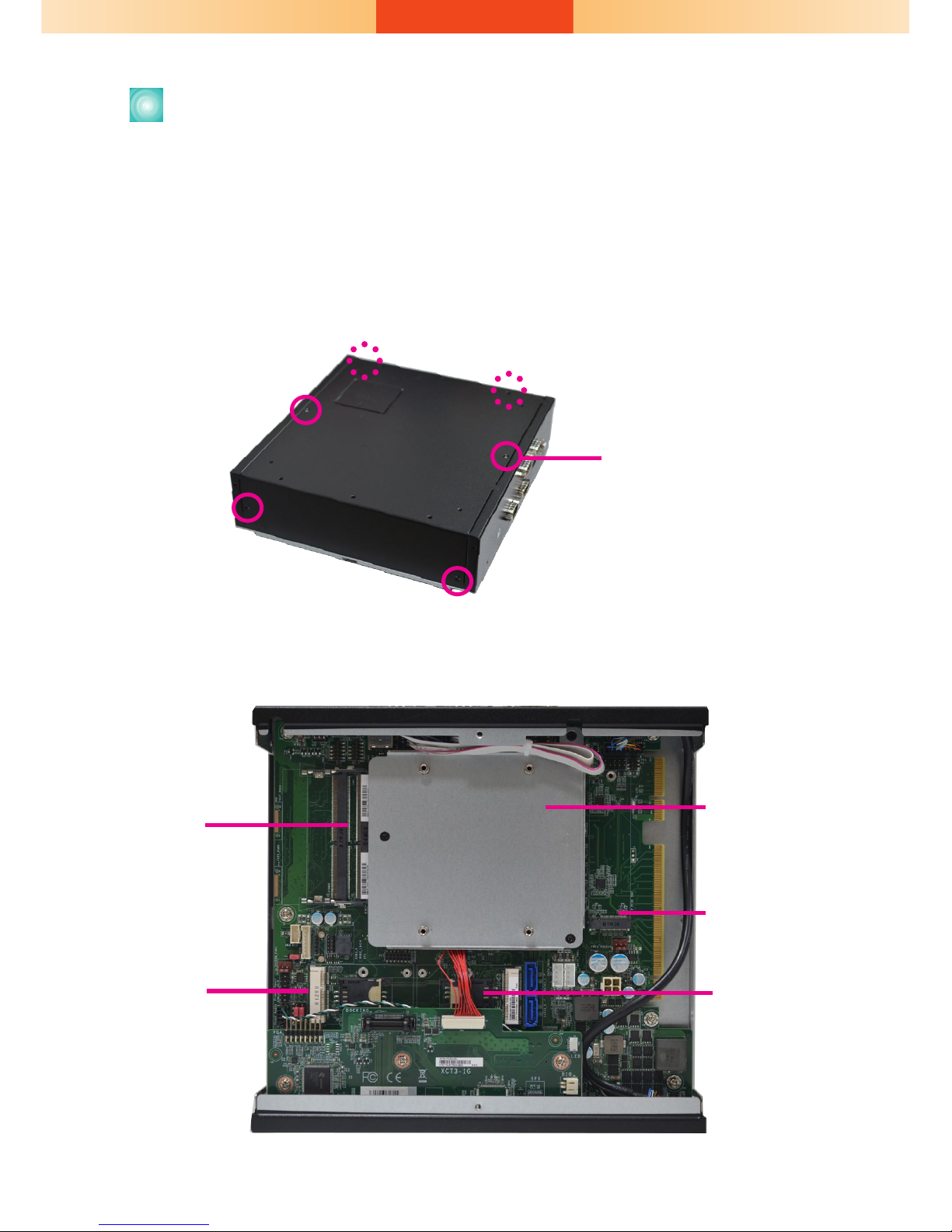
Removing the Chassis Cover
1. Make sure the system and all other peripheral devices connected to it
have been powered-off.
2. Disconnect all power cords and cables.
3. The 6 mounting screws on the rear side of the system are used to
secure the cover to the chassis. Remove these screws and put them in a
safe place for later use.
4. Lift the cover to open the system.
5. The Mini PCIe, M.2 and the SODIMM slots are readily accessible after
removing the chassis cover.
SODIMM
Socket
Mini PCIe
Sockets
M.2 Socket
SATA drive bay
SIM card slot
Mounting Screw
4
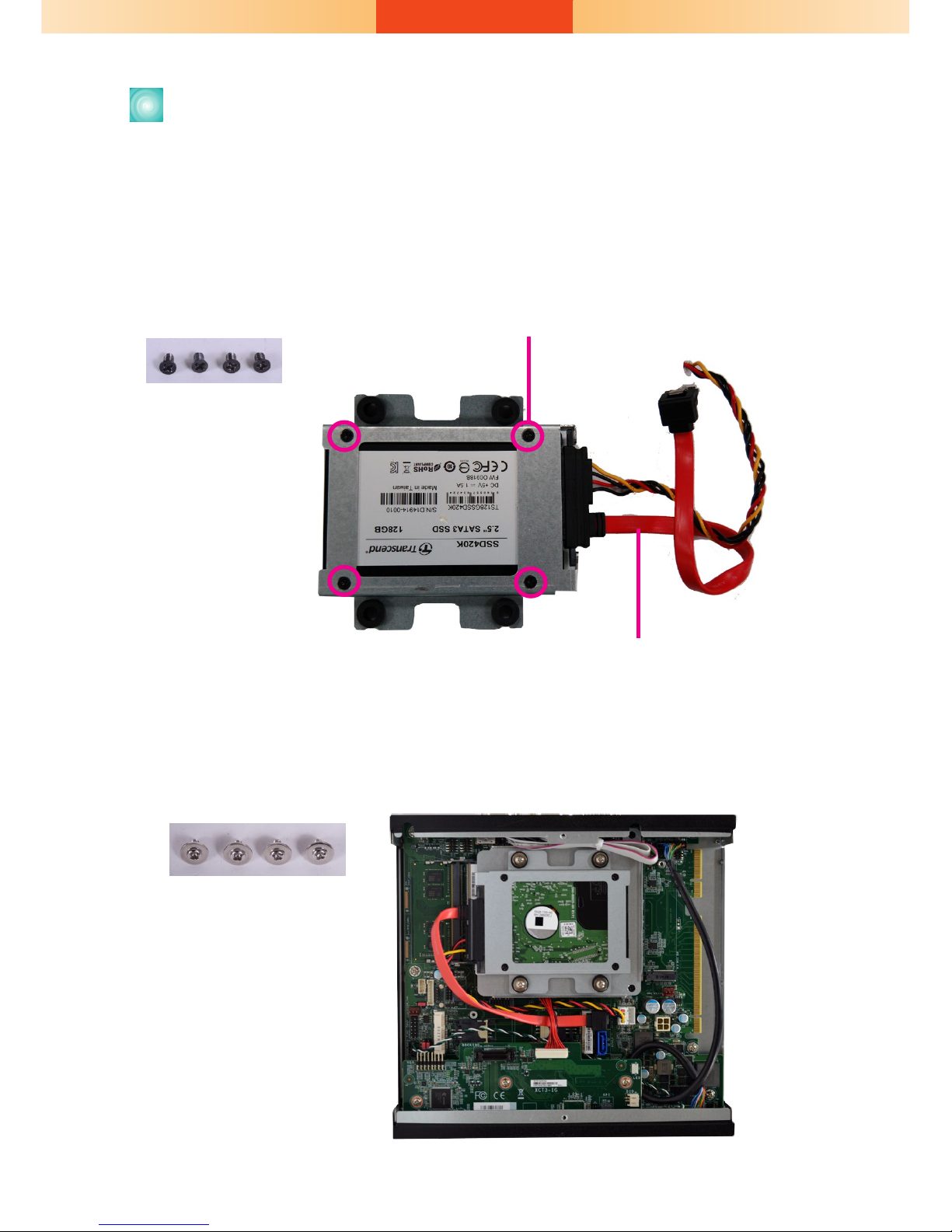
The system can accommodate one SATA drive. Please use the following
procedure to install a SATA drive in the system.
1. Before installing the SATA drive, connect the SATA data/power cable
to the SATA data connector of the SATA drive. Then install the SATA
drive onto the HDD bracket with the provided mounting screws.
Installing a SATA Drive
Mounting Screws
Mounting screws
SATA data and power cable
2. Place the SATA drive installed with the HDD bracket in the system.
Align the mounting holes on the HDD bracket with the mounting holes
on the drive bay and use the provided mounting screws to secure the
drive in place.
Mounting Screws

5
3. Connect the other end of the SATA data/power cable to the SATA data
and power connectors on the system board respectively.
SATA power connector
SATA data connector
6
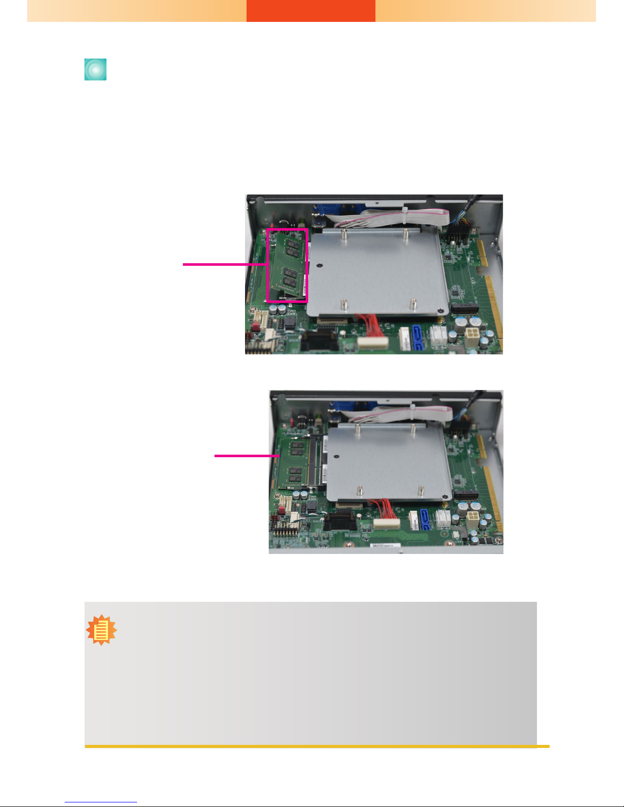
Installing a SODIMM
The system supports two DDR4 SODIMM socket. To install a memory module, grasp the memory module by its edges and align the module’s notch
with the socket’s notch; then insert the memory into the socket at an
angle and push it down until you feel a click.
SODIMM module
installed into the socket
Notes:
1. The system supports dual-channel conguration. To enable dual-channel,
populate both SODIMM sockets.
2. If installing only one memory module, please install it on the memory socket
labeled DIMM 1 (the one closer to the center of the board).
3. The SODIMM sockets can only accept DDR4 memory modules. Please do not
install other types of memory modules. The SKUs with Intel® CM238 Chipset
support ECC memory.
Insert the memory
at an angle
 Loading...