

Page 1
www.d.com
1
Chapter 1 Introduction
KS211/212
7” Touch Panel PC
User’s Manual
A27010427
Page 2

www.dfi .com
2
Chapter 1 Introduction
Copyright
This publication contains information that is protected by copyright. No part of it may be reproduced in any form or by any means or used to make any transformation/adaptation without
the prior written permission from the copyright holders.
This publication is provided for informational purposes only. The manufacturer makes no
representations or warranties with respect to the contents or use of this manual and specifically disclaims any express or implied warranties of merchantability or fitness for any particular
purpose. The user will assume the entire risk of the use or the results of the use of this document. Further, the manufacturer reserves the right to revise this publication and make changes
to its contents at any time, without obligation to notify any person or entity of such revisions
or changes.
© 2014. All Rights Reserved.
Trademarks
Product names or trademarks appearing in this manual are for identification purpose only and
are the properties of the respective owners.
FCC and DOC Statement on Class B
This equipment has been tested and found to comply with the limits for a Class B digital
device, pursuant to Part 15 of the FCC rules. These limits are designed to provide reasonable protection against harmful interference when the equipment is operated in a residential
installation. This equipment generates, uses and can radiate radio frequency energy and, if not
installed and used in accordance with the instruction manual, may cause harmful interference
to radio communications. However, there is no guarantee that interference will not occur in a
particular installation. If this equipment does cause harmful interference to radio or television
reception, which can be determined by turning the equipment off and on, the user is encouraged to try to correct the interference by one or more of the following measures:
• Reorient or relocate the receiving antenna.
• Increase the separation between the equipment and the receiver.
• Connect the equipment into an outlet on a circuit different from that to which the receiver
is connected.
• Consult the dealer or an experienced radio TV technician for help.
Notice:
1. The changes or modifications not expressly approved by the party responsible for compli-
ance could void the user’s authority to operate the equipment.
2. Shielded interface cables must be used in order to comply with the emission limits.
Page 3

www.d.com
3
Chapter 1 Introduction
Table of Contents
Copyright ����������������������������������������������������������������������������������������������������������� 2
Trademarks ������������������������������������������������������������������������������������������������������� 2
FCC and DOC Statement on Class B ���������������������������������������������������2
About this Manual �����������������������������������������������������������������������������������������4
Warranty ������������������������������������������������������������������������������������������������������������4
Static Electricity Precautions ��������������������������������������������������������������������4
Safety Measures ��������������������������������������������������������������������������������������������4
About the Package ���������������������������������������������������������������������������������������5
Chapter 1 - Introduction ���������������������������������������������������������������������������6
Overview ������������������������������������������������������������������������������������������������������� 6
Key Features ������������������������������������������������������������������������������������������������6
Specifications ����������������������������������������������������������������������������������������������� 7
Getting the Know the KS211/212 ����������������������������������������������������������9
Mechanical Dimensions ��������������������������������������������������������������������������� 10
Chapter 2 - Installation �������������������������������������������������������������� 11
Connecting Cables to Terminal Blocks ����������������������������������������������� 11
Removing the Chassis Cover ������������������������������������������������������������������12
Chapter 3 - Hardware Installation �������������������������������������������� 13
Board Layout ���������������������������������������������������������������������������������������������13
System Memory ���������������������������������������������������������������������������������������� 13
Jumper Settings ���������������������������������������������������������������������������������������� 13
Top Panel I/O Port ����������������������������������������������������������������������������������� 16
Side Panel I/O Port ���������������������������������������������������������������������������������� 16
Bottom Panel I/O Ports ��������������������������������������������������������������������������17
Chapter 4 - Mounting Options �������������������������������������������������������������� 22
Wall Mount ������������������������������������������������������������������������������������������������� 22
Panel Mount �����������������������������������������������������������������������������������������������23
Appendix A - BSP User Guide ��������������������������������������������������������������� 22
Appendix B – Android BSP Known Issue ����������������������������������������35
Page 4

www.dfi .com
4
Chapter 1 Introduction
About this Manual
An electronic file of this manual is included in the CD. To view the user’s manual in the CD, insert the CD into a CD-ROM drive. The autorun screen (Main Board Utility CD) will appear. Click
“User’s Manual” on the main menu.
Warranty
1. Warranty does not cover damages or failures that arised from misuse of the product,
inability to use the product, unauthorized replacement or alteration of components and
product specifications.
2. The warranty is void if the product has been subjected to physical abuse, improper installation, modification, accidents or unauthorized repair of the product.
3. Unless otherwise instructed in this user’s manual, the user may not, under any circumstances, attempt to perform service, adjustments or repairs on the product, whether in or
out of warranty. It must be returned to the purchase point, factory or authorized service
agency for all such work.
4. We will not be liable for any indirect, special, incidental or consequencial damages to the
product that has been modified or altered.
Important:
Static Electricity Precautions
It is quite easy to inadvertently damage your PC, system board, components or devices even
before installing them in your system unit. Static electrical discharge can damage computer
components without causing any signs of physical damage. You must take extra care in handling them to ensure against electrostatic build-up.
1. To prevent electrostatic build-up, leave the system board in its anti-static bag until you are
ready to install it.
2. Wear an antistatic wrist strap.
3. Do all preparation work on a static-free surface.
4. Hold the device only by its edges. Be careful not to touch any of the components, contacts
or connections.
5. Avoid touching the pins or contacts on all modules and connectors. Hold modules or con
nectors by their ends.
Safety Measures
To avoid damage to the system:
• Use the correct AC input voltage range.
To reduce the risk of electric shock:
• Unplug the power cord before removing the system chassis cover for installation or servic-
ing. After installation or servicing, cover the system chassis before plugging the power cord.
Battery:
• Danger of explosion if battery incorrectly replaced.
• Replace only with the same or equivalent type recommend by the manufacturer.
• Dispose of used batteries according to local ordinance.
Electrostatic discharge (ESD) can damage your processor, disk drive and other components.
Perform the upgrade instruction procedures described at an ESD workstation only. If such a station is not available, you can provide some ESD protection by wearing an antistatic wrist strap
and attaching it to a metal part of the system chassis. If a wrist strap is unavailable, establish
and maintain contact with the system chassis throughout any procedures requiring ESD protection.
Page 5

www.dfi .com
5
Chapter 1 Introduction
About the Package
The package contains the following items. If any of these items are missing or damaged,
please contact your dealer or sales representative for assistance.
• 1 7” Touch Panel PC
• 3 Terminal blocks
• 1
24V power adapter
• 1 CD disk includes: Manual
• 1 Quick Installation Guide
Optional Items
• Wall Mount kit
• Panel Mount kit
• Power Cord
The board and accessories in the package may not come similar to the information listed
above. This may differ in accordance to the sales region or models in which it was sold. For
more information about the standard package in your region, please contact your dealer or
sales representative.
Safety Precautions
• Use the correct DC input voltage range.
• Unplug the power cord before removing the system chassis cover for installation or servicing. After installation or servicing, cover the system chassis before plugging the power cord.
• Danger of explosion if battery incorrectly replaced.
• Replace only with the same or equivalent type recommend by the manufacturer.
• Dispose of used batteries according to local ordinance.
• Keep this system away from humidity.
• Place the system on a stable surface. Dropping it or letting it fall may cause damage.
• The openings on the system are for air ventilation to protect the system from overheating.
DO NOT COVER THE OPENINGS.
• Place the power cord in such a way that it will not be stepped on. Do not place anything on
top of the power cord. Use a power cord that has been approved for use with the system
and that it matches the voltage and current marked on the system’s electrical range label.
• If the system will not be used for a long time, disconnect it from the power source to avoid
damage by transient overvoltage.
• If one of the following occurs, consult a service personnel:
- The power cord or plug is damaged.
- Liquid has penetrated the system.
- The system has been exposed to moisture.
- The system is not working properly.
- The system dropped or is damaged.
- The system has obvious signs of breakage.
• The unit uses a three-wire ground cable which is equipped with a third pin to ground the
unit and prevent electric shock. Do not defeat the purpose of this pin. If your outlet does
not support this kind of plug, contact your electrician to replace the outlet.
• Disconnect the system from the DC outlet before cleaning. Use a damp cloth. Do not use
liquid or spray detergents for cleaning.
Page 6
www.dfi .com
6
Chapter 1 Introduction
Chapter 1 - Introduction
Chapter 1
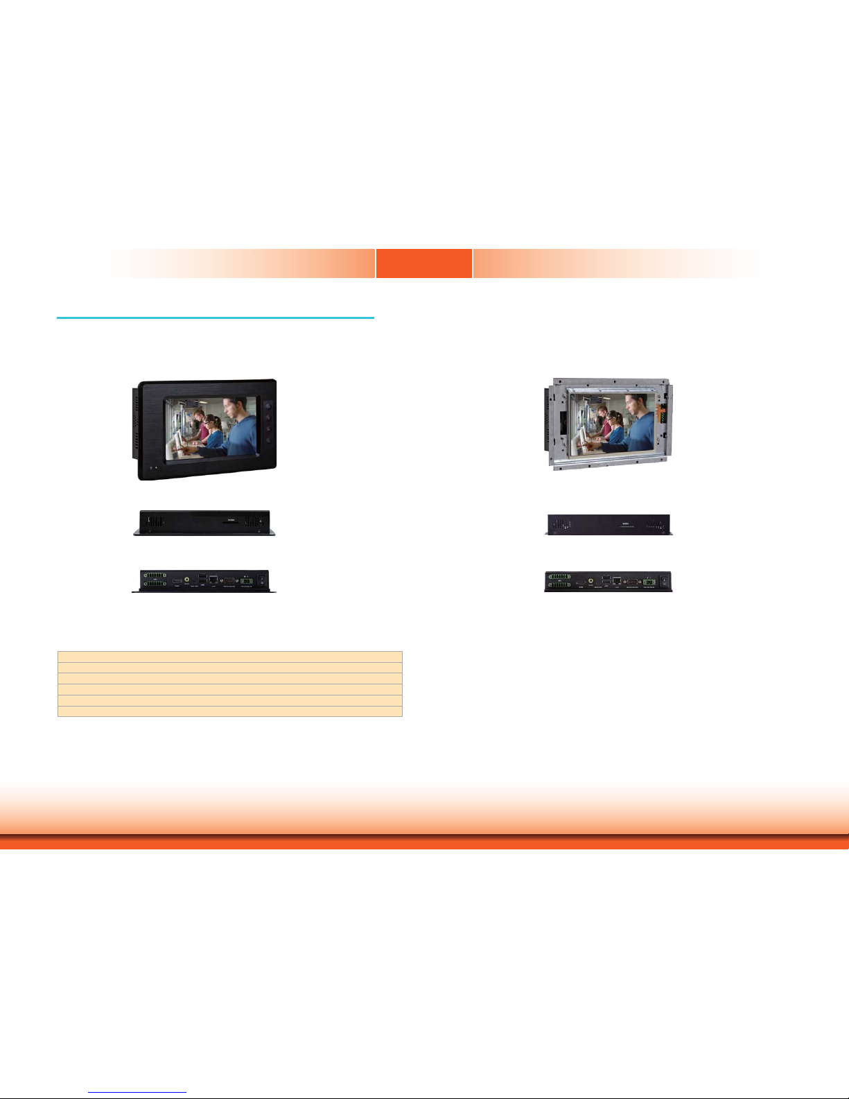
Overview
KS211
KS212
Top View
Bottom View
Side View
Top View
Bottom View
Side View
Key Features
• 7" WVGA Touch Screen Fanless Panel PC
• 1GB DDR3 onboard
• 4GB eMMC onboard
• 4 customizable function keys (KS211)
• 1 SD/MMC socket
• 1 HDMI, 2 USB 2.0, 1 Mini USB, 1 LAN, 1 COM, 12-bit GPIO
Page 7

www.dfi .com
7
Chapter 1 Introduction
EXPANSION
SLOTS
• 1 Mini PCIe slot (DFI Proprietary)
- Supports half size Mini PCIe card
- Supports USB interface for 3G module
• 1 SIM card slot
POWER • 9~30Vdc (+/-10%) power input voltage
FRONT PANEL
PROTECTION
• IP65 (Dust Tight; Water Proof protection)
CONSTRUCTION
• Aluminum front bezel, rugged metal housing
MOUNTING
• Wall mount (VESA 75x75)
• Panel mount (Mounting clamp)
ENVIRONMENT • Temperature
- Operating: -15oC ~ 60oC
- Storage: -30oC ~ 80oC
• Relative Humidity
- 95% RH at 60oC
DIMENSIONS • 235mm x 150mm x 40.80mm (W x H x D)
WEIGHT
•
2.10 kg
OS SUPPORT• Android 2.3
• LTIB Linux 2.6.35.3
Specifications
KS211
PROCESSOR • Freescale i.MX535
- ARM Cortex-A8 core
- Processor speed: up to 1GHz
SYSTEM MEMORY • DDR3 onboard
• Onboard
memory
- 1GB: standard
- 2GB: option
LCD and
TOUCH SCREEN
• 7” (800x480) WVGA TFT touch screen LCD
• Supports touch screen
- TI
®
TSC2004 touch screen controller
• 400 NITS
• 4-Wire Resistive touch screen
STORAGE • 8Mbit EEPROM (option)
•
1 SD/MMC socket
• Supports 4GB (standard), 8GB and 16GB eMMC onboard
ONBOARD LAN
FEATURES
• SMSC 8710 10/100 Ethernet transceiver
AUDIO • SGTL5000 2-channel audio codec
• 2 built
-in 2W speakers (left and right sides)
• 1 Line-out
GPIO
• 1 12-bit GPIO connector (6 bit in/6 bit out, with power)
I/O PORTS • Front
- 1 Power LED
- 4 function keys
• Bottom
- 1 DB-9 RS232/422/485 serial port
- 1 HDMI port
- 1 Mini USB port (device Type B)
- 2 USB 2.0/1.1 ports (Type A)
- 1 Line-out jack
- 12-bit GPIO (2 7-pole terminal blocks)
- 1 2-pin 9-30V DC-in jack
- 1 power switch
- 1 LAN port
• Side
- 2 built-in 2W speakers (left and right sides)
• Top
- 1 SD/MMC card socket
Chapter 1
Page 8

www.dfi .com
8
Chapter 1 Introduction
Chapter 1
Specifications
KS212
EXPANSION
SLOTS
• 1 Mini PCIe slot (DFI Proprietary)
- Supports half size Mini PCIe card
- Supports USB interface for 3G module
• 1 SIM card slot
POWER • 9~30Vdc (+/-10%) power input voltage
CONSTRUCTION
• Aluminum front bezel, rugged metal housing
FRONT PANEL
PROTECTION
• IP65 (Dust Tight; Water Proof protection)
MOUNTING •
VESA 75x75
ENVIRONMENT • Temperature
- Operating: -15oC ~ 60oC
- Storage: -30oC ~ 80oC
• Relative Humidity
- 95% RH at 60oC
DIMENSIONS • 230.40mm x 142.32mm x 35.80mm
WEIGHT
•
1.90 kg
OS SUPPORT• Android 2.3
• LTIB Linux 2.6.35.3
PROCESSOR • Freescale i.MX535
- ARM Cortex-A8 core
- Processor speed: up to 1GHz
SYSTEM MEMORY • DDR3 onboard
• Onboard
memory
- 1GB (standard)
- 2GB: option
LCD and
TOUCH SCREEN
• 7” (800x480) WVGA TFT touch screen LCD
• Supports touch screen
- TI
®
TSC2004 touch screen controller
• 400 NITS
• 4-Wire Resistive touch screen
STORAGE • 8Mbit EEPROM (option)
•
1 SD/MMC socket
• Supports 4GB (standard), 8GB and 16GB eMMC onboard
ONBOARD LAN
FEATURES
• SMSC 8710 10/100 Ethernet transceiver
AUDIO • SGTL5000 2-channel audio codec
• 2 built
-in 2W speakers (left and right sides)
• 1 Line-out
GPIO
• 1 12-bit GPIO connector (6 bit in/6 bit out, with power)
I/O PORTS • Bottom
- 1 DB-9 RS232/422/485 serial port
- 1 HDMI port
- 1 Mini USB port (device T
ype B)
- 2 USB 2.0/1.1 ports (Type A)
- 1 Line-out jack
- 12-bit GPIO (2 7-pole terminal blocks)
- 1 2-pin 9-30V DC-in jack
- 1 power switch
- 1 LAN port
• Side
- 2 built-in 2W speakers (left and right sides)
• Top
- 1 SD/MMC card socket
Page 9
www.dfi .com
9
Chapter 1 Introduction
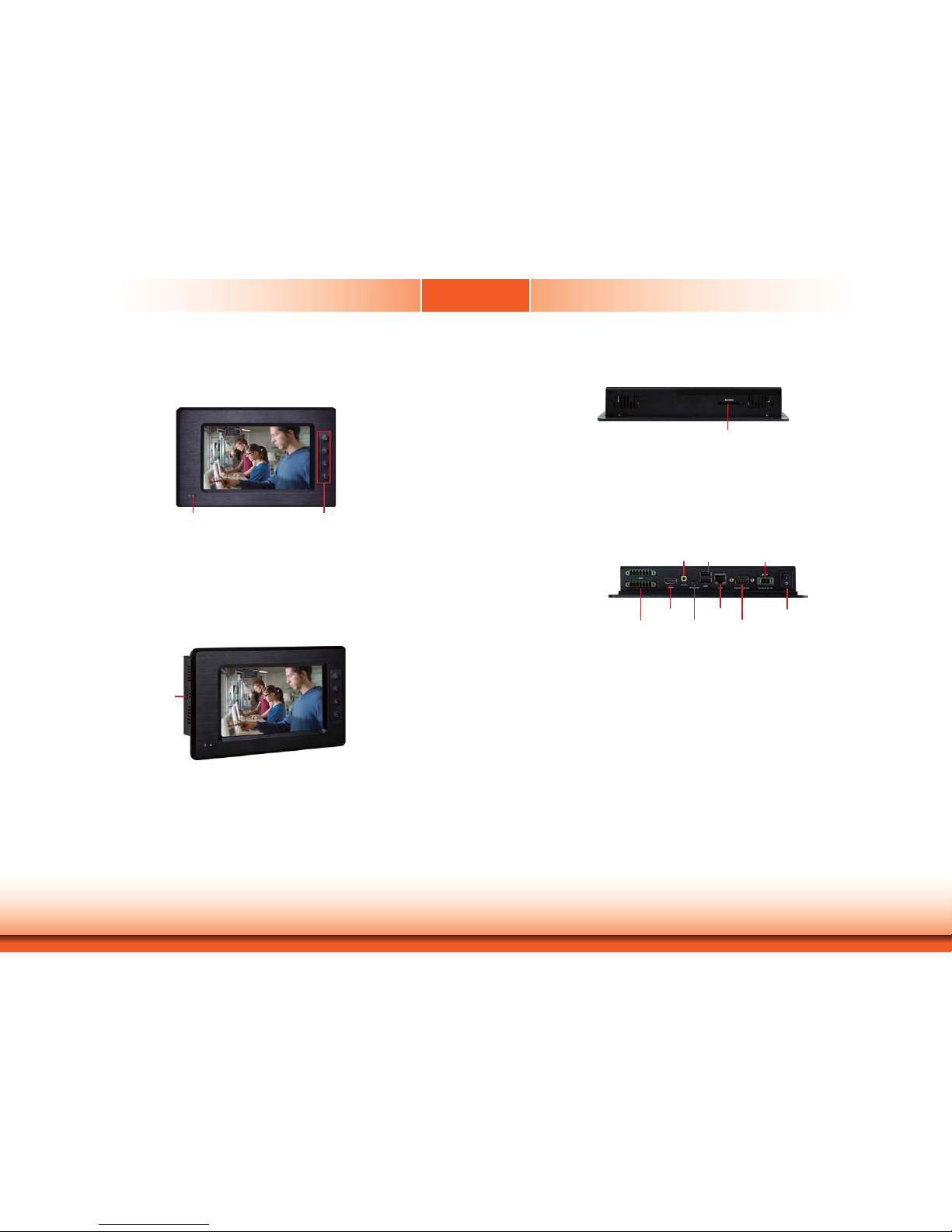
Getting to Know the KS211/212
Chapter 1
Front View
Power LED
Indicates the power status of the system.
Function Keys (KS211)
Used to navigate through the pages.
Top View
SD/MMC
Indicates to insert and SD and MMC.
Bottom View
COM
Used to connect a serial device.
Mini USB
Used to connect a Mini USB device (only as client).
USB
Used to connect USB 2.0/1.1 devices.
LAN
Used to connect the system to a local area network.
GPIO
Supports 6-bit input and 6-bit output GPIO connector (with power).
Line-out
Used to connect to a speaker.
DC-in
Used to plug a power adapter.
Power Switch
Press to power-on or power-off the system.
HDMI
Used to connect an HDMI device.
Power LED Function Keys
SD/MMC
2W built-in speaker
Side View
Speaker
Bult-in with 2W speaker in the right and left sides.
Power Switch
Line-out
USB 9-30V DC-in
HDMI
RS232/422/485 COM
12-bit GPIO
Mini USB
LAN
Page 10
www.dfi .com
10
Chapter 1 Introduction
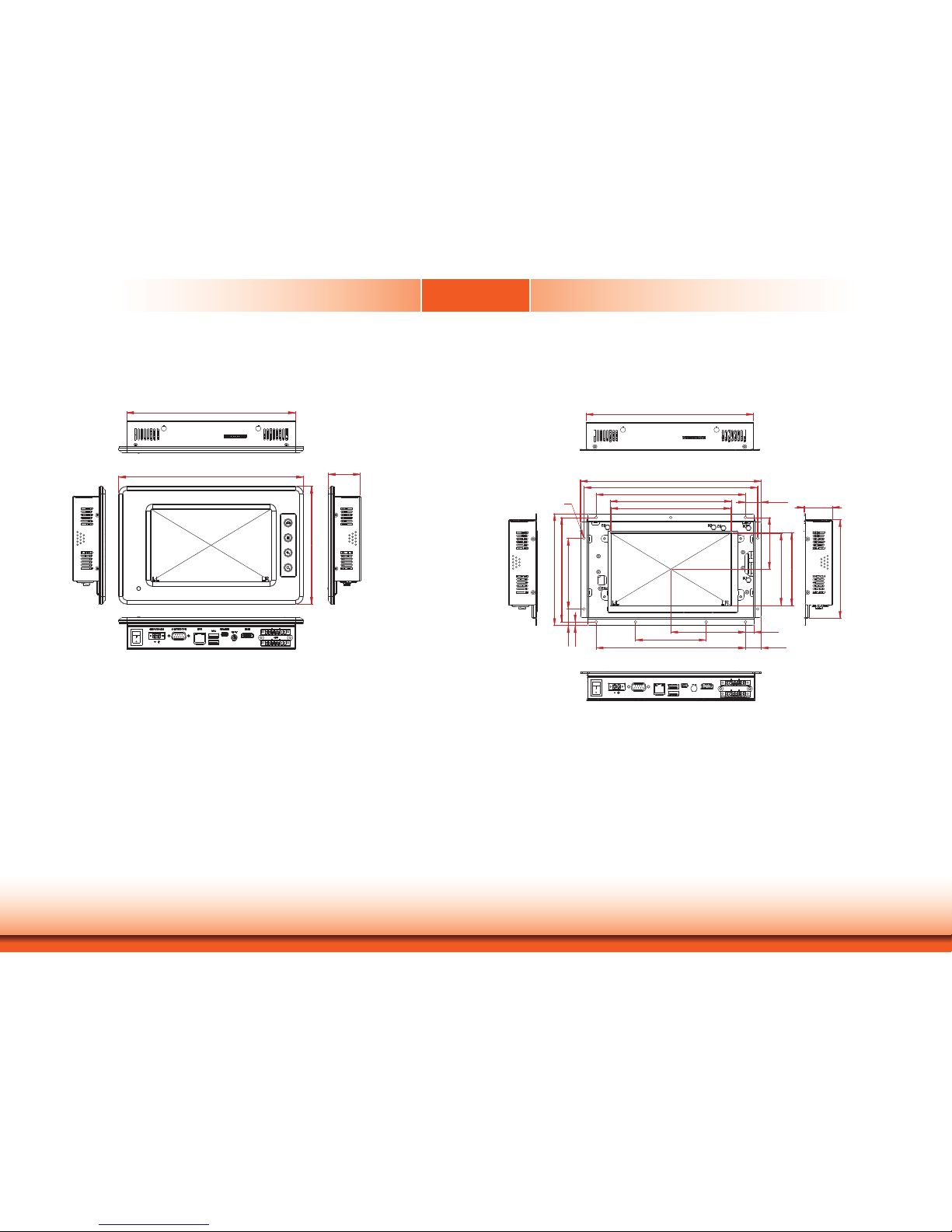
Mechanical Dimensions
KS211
KS212
Chapter 1
Left View
214.60
235.00
150.00
40.80
Bottom View
Right View
Top View
Front View
125.60
35.80
90.00
20.99
4.49
133.00
142.32
11.2095.00
20.20190.00
90.00
153.00 (A,A FOR T/P)
154.40 (V,A FOR T/P)
190.00
221.00
230.40
20.20
65.85
92.04
93.40
214.60
(A,A FOR T/P)
(V,A FOR T/P)
Ø3.50
Bottom View
Right View
Top View
Front ViewLeft View
Page 11

www.d.com
11
Chapter 2 Installation
Chapter 2 - Installation
Chapter 2
Connecting Cables to Terminal Blocks
Important:
When installing the touch panel PC, make sure the power is off. Failure to turn off, may cause
severe damage to the system.
1. Insert the cable end of the power adaptor to the terminal block. To firmly fix the cable into
the terminal block, use a screwdriver to clamp down the wires to the screw that is in the
terminal block.
2. Plug the terminal block into the DC-in connector and then tighten the screws to secure the
terminal block in place.
Terminal block
Wire
Power adapter cable
DC-in
connector
Screws
White Wire
Black Wire
+ -
Page 12

www.d.com
12
Chapter 2 Installation
1. Make sure the system and all other peripheral devices connected to it has been poweredof f.
2. Disconnect all power cords and cables.
3. The 8 mounting screws on the rear side of the system are used to secure the cover to the
chassis. Remove these screws and then put them in a safe place for later use.
Removing the Chassis Cover
Mounting Screw
4. After removing the mounting screws, lift the cover up.
5. The Mini PCIe slot and SIM card slot are readily accessible after removing the chassis
cover.
Lift the Cover Upward
Mini PCIe Slot
SIM card slot
Mounting Screw
Chapter 2
Page 13

www.d.com
13
Chapter 3 Hardware Installation
Chapter 3
Chapter 3 - Hardware Installation
Board Layout
1ON23456
SW4
1
10
3
COM1
debug
port
1
109
2
Power LED
Chassis Intrusion
Freescale
i.MX535
DDR3
1
Clear CMOS
(JP1)
RTC_Battery
DDR3
1
39
LVDS
2
40
1
AMP_R
VGA
1
15
2
16
Reset
Power Button
JTAG
1
2
11
12
SW28
SW29
456 1
ON
2378
456 1
ON
2378
3G LED
MIC
AMP_L
SIM
1
13
14
2
DIO
USB 6-7
3G_Modem
1
2
9
10
HDMI Chip
Sil9022
Audio Chip
SGTL5000
LAN Chip
SMSC 8710
Panel Power
Select
(J11)
UART 2 Chip
SP338
PMIC
DA9053
COM2 RS232/422/485
HW/SW Mode Select(JP7)
112
2
12
1
1
1
+ -
MMC/SD
HDMI
Line-out
Mini USB
LAN
USB 4-5
COM2
DC-in
System Memory
DDR3
Important:
Electrostatic discharge (ESD) can damage your board, processor, disk drives, add-in
boards, and other components. Perform installation procedures at an ESD workstation
only. If such a station is not available, you can provide some ESD protection by wearing an antistatic wrist strap and attaching it to a metal part of the system chassis. If
a wrist strap is unavailable, establish and maintain contact with the system chassis
throughout any procedures requiring ESD protection.
Important:
When the Standby Power LED lit red, it indicates that there is power on the system
board. Power-off the PC then unplug the power cord prior to installing any devices.
Failure to do so will cause severe damage to the motherboard and components.
•DDR3onboard
•Onboardmemory
- 1GB: standard
- 2GB: optional
Power LED
Features
DDR3
DDR3
eMMC
Touch
Screen
5
1
Android Hot Key Connector
Top View
Bottom View
Page 14

www.d.com
14
Chapter 3 Hardware Installation
Chapter 3
Jumper Settings
Clear CMOS Data
If you encounter the following,
a) CMOSdatabecomes corrupted.
b) You forgot the supervisor or user password.
youcanreconfigurethesystemwith thedefaultvalues storedintheROM BIOS.
Toloadthedefault valuesstoredinthe ROMBIOS,please followthesteps below.
1. Power-off the system and unplug the power cord.
2. SetJP1pins2and 3toOn. Waitforafew secondsandset JP1backto itsdefaultsetting,
pins1 and2On.
3. Now plug the power cord and power-on the system.
JP1
2-3On:
ClearCMOS Data
1-2On:
Normal (default)
3
1
2
3
1
2
COM RS232/RS422/RS485 Select
SW4(forCOM2)isusedto configuretheCOM porttoRS232, RS422(FullDuplex) orRS485.
JP7is usedtoconfigurethe COMportset viathehardware modeorsoftwaremode.
Note:
IfyouusetheSW4to selectRS232/RS422/ RS485,makesure JP7isset viathe
“Hardware Mode”.
12
10
3
1
1-4-7-10,2-5-8-11 On:
Software Mode (default)
2-5-8-11,3-6-9-12 On:
Hardware Mode
12
10
3
1
RS232/RS422/RS485 Select: COM (SW4)
RS232
1On,2-3Off
RS422
1,2On,3Off
RS485
2On,1,3Off
SW4
JP7
COM:
RS232/422/485
Page 15

www.d.com
15
Chapter 3 Hardware Installation
Chapter 3
Panel Power Select MMC/SD Mode Select
2-3On:
+3.3V (default)
1-2On: +5V
J11 is used to select the power that supplies with the LVDS panel.
Important:
Before powering-on the system, make sure J11’s setting matches the LVDS panel’s
specification. Selecting the incorrect voltage will seriously damage the LVDS panel.
J11
3
1
2
3
1
2
SW28 SW29
MMC/SD Mode SW29 SW28
Program Mode
All off 5,6On
eMMC Boot
2,3,4,7On 1On
SD Boot
2On All off
SW28and SW29areusedto settheMMC/SD Cardsocketvia theselectionsof ProgramMode,
eMMC Boot, or SD Boot.
Page 16

www.dfi .com
16
Chapter 3 Ports and Connectors
Ports and Connectors
Top Panel I/O Port
Chapter 3
SD/MMC
The front panel I/O port consist of the following:
• 1 SD/MMC card socket
SD/MMC
SD/MMC
card socket
This expansion port is used to insert a Secure Digital (SD) or Multimedia Card (MMC) device.
Aside from storing data files, an SD card is also capable of storing powerful software applications.
Side Panel I/O Port
2W built-in speaker
The side panel I/O port consist of the following:
• 2 2W built-in speaker (right and left sides)
Built-in Speaker
1
AOUT_R+
AOUT_R-
AOUT_L+
AOUT_L-
The amplify connectors right/left which have amplifying feature are used to connect external
speakers. Using the same signal cable to connect with external speaker.
1
AMP_R
AMP_L
Page 17

www.dfi .com
17
Chapter 3 Ports and Connectors
Chapter 3
Bottom Panel I/O Ports
The bottom panel I/O ports consist of the following:
• 1 12-bit GPIO (6-bit in/6-bit out)
• 1 HDMI port (Type B)
• 1 Mini USB port
• 1 Line-out jack
• 1 RS232/422/485 COM port
• 1 LAN port
• 2 USB 2.0/1.1 ports (Type A)
• 1 DC-in
GPIO
17
8 14
Power Switch
Line-out
USB 9-30V DC-in
HDMI
RS232/422/485 COM
12-bit GPIO
Mini USB
LAN
8
The 12-bit Digital I/O (6-bit input and 6-bit output) connector provides powering-on function
to external devices that are connected to these connectors. The pin functions of the digital I/O
connector are listed below:
GPIO Connector
Pins Function Pins Function
1
DIO_OUT-1
8
DIO_IN-4
2
DIO_IN-1
9
DIO_OUT-5
3
DIO_OUT-2
10
DIO_IN-5
4
DIO_IN-2
11
DIO_OUT-6
5
DIO_OUT-3
12
DIO_IN-6
6
DIO_IN-3
13 DC_5V_BB
7
DIO_OUT-4 14 GND
Page 18

www.dfi .com
18
Chapter 3 Ports and Connectors
HDMI
The HDMI interface which carries both digital audio and video signals is used to connect a LCD
monitor or digital TV that has the HDMI port.
HDMI
Note:
The graphics features are controlled by CPU. When HDMI and LVDS displays
simultaneously, the system board transmits video signals from HDMI port only. The
LVDS works on the system board will make the screen dark.
Mini USB
Mini USB
The Mini USB is a device that can act as client role. It indicates the concept of one-to-one
connection between two devices which are connected directly in order to transfer data
bilaterally.
Chapter 3
Page 19

www.dfi .com
19
Chapter 3 Ports and Connectors
Chapter 3
Line-out
The line-out jack is used to connect a headphone or external speakers.
Line-out
COM (Serial) Port
COM:
RS232/422/485
The pin function of COM port will vary according to JP7/SW4’s settings. Refer to “COM RS232/
RS422/RS485 Select” in this chapter for more information.
The serial COM port is an asynchronous communication port with 16C550A-compatible UARTs
that can be used with modems, serial printers, remote display terminals, and other serial
devices.
Page 20

www.dfi .com
20
Chapter 3 Ports and Connectors
Chapter 3
USB 2.0/1.1 Ports
USB allows data exchange between your computer and a wide range of simultaneously accessible external Plug and Play peripherals.
The system board is equipped with two onboard USB 2.0/1.1 ports (USB 4-5). The 10-pin connector allow you to connect two additional USB 2.0/1.1 ports (USB 6-7). The additional USB
ports may be mounted on a card-edge bracket. Install the card-edge bracket to an available
slot at the rear of the system chassis and then insert the USB port cables to a connector.
LAN Port
The LAN port allows the system board to connect to a local area network by means of a
network hub.
Features
• SMSC 8710 10/100M Ethernet transceiver
LAN
10
VCC
-Data
+Data
GND
Key
VCC
-Data
+Data
GND
N.C.
9
1
2
USB 2.0
USB 6-7
USB 2.0
Page 21

www.dfi .com
21
Chapter 3 Ports and Connectors
This DC-in terminal block provides a maximum of 60W power and is considered a low power
solution. Connect a DC power cord to this jack. Use a power adapter with 9~30V DC output
voltage. Using a voltage higher than the recommended one may fail to boot the system or
cause damage to the system board.
9~30V DC-in
DC-in
Chapter 3
Page 22

www.dfi .com
22
Chapter 4 Mounting Options
Chapter 4 - Mounting Options
Chapter 4
Wall Mount
The wall mount kit includes the following:
• 2 Wall mount brackets
• Bracket screws
Wall mount bracket 1 Wall mount bracket 2
1. Select a place on the wall where you will mount the Panel PC.
2. Use the provided mounting screws to attach “wall mount bracket 1” to the wall.
Wall mount bracket 1
Mounting screw
4. Using the hooks on “bracket 2”, slide the Panel PC to “bracket 1”.
Wall mount bracket 1
Wall mount bracket 2
3. Attach the other bracket (wall mount bracket 2) to the rear of the Panel PC.
Wall mount bracket 2
Mounting screw
Hooks
5. Tighten the screw to hold the assembly in place.
Mounting screw
Page 23

www.dfi .com
23
Chapter 4 Mounting Options
Panel Mount
The panel mounting kit includes the following:
• 6 mounting clamps
1. Select a place on the panel where you will mount the Panel PC.
2. Cut out a shape on the panel that corresponds to the Panel PC’s rear dimensions
(217.6mm x 128.6mm).
128.60
217.60
3. Stick the poron foam on the rear panel.
Poron foam
Poron foam
Page 24

www.dfi .com
24
Chapter 4 Mounting Options
Chapter 4
4. Slide the Panel PC through the hole until it is properly fi tted against the panel.
5. Position the mounting clamps along the rear edges of the Panel PC, fi tting them into the slits
that are around the Panel PC.
Slit for mounting
the clamp
Mounting
clamp
White plastic
cap
6. The fi rst and second clamps must be positioned and secured diagonally prior to mounting the
rest of the clamps. Tighten the clamp’s screw using an electric screwdriver until the white
plastic cap touches the panel. Do not over tighten the screws to prevent damaging the Panel
PC. The illustration below shows all clamps properly mounted.
Panel wall
128.60
217.60
Page 25

www.dfi .comAppendix A BSP User Guide
25
Appendix A
Appendix A - BSP User Guide
Build Android for FS200-M53
Get Android Source Code (Android/Kernel/uboot)
Please get an Android BSP from DFI for implementing your android system, which contains
the bootloader (uboot), kernel code, and android system, as well as tool chain, on the FS200
board. You can find out a compressed file named ‘Android_2_3_7_sources_v115_3G.tar.gz’.
Supposed that you works in the linux system. Please use linux commands to extract this
compressed file.
#tar –zxvf Android_2_3_7_sources_v115_3G.tar.gz
After extracting this compressed file, you can find out the specified folder, Android_2_3_7_
sources_v115_3G, containing several sub-folders that include uboot , kernel, android system
and tool chain folders, respectively.
Find folders
Please enter the ‘Android_2_3_7_sources_v115_3G’ folder to find out the following sub-folders.
• Bootable – represents the uboot folder
• Kernel_imx – represents the kernel system
• Prebuilt/linux-x86/toolchain – this folder contains all relevant tool compilers to build up
several systems.
• Others – represents all files used for android system
Build Uboot Images
Before building up uboot images, please set up the working environments described in the
following table on the right.
Assumed that your root folder is Android_2_3_7_sources_v115_3G.
$cd Android_2_3_7_sources_v115_3G/bootable/bootloader/uboot-imx
$export ARCH=arm
$export
CROSS_COMPILE=~/android_fs200/Android_2_3_7_sources_v115_3G/prebuilt/linux-x86/toolchain/arm-eabi-4.3.1/bin/arm-eabi$make distclean
$make mx53_smd_android_config
$make
After finishing ‘make’ command, it will generate the uboot image located in the
~/Android_2_3_7_sources_v115_3G/bootable/bootloader/uboot-imx folder.
"u-boot.bin" is generated if you have built it up successfully.
The u-boot.bin has 1024 Bytes padding at the head of file, for example, first executable
instruction is at the offset 1KB. If you want to generate a no-padding image, you have to do
dd command in host listed below.
$ sudo dd if=./u-boot.bin of=./u-boot-no-padding.bin bs=1024 skip=1; sync
This no-padding uboot image is usually used in the SD card, for example, programming this
no-padding uboot image into 1KB offset of SD card so that we do not overwrite the MBR
(including partition table) within first 512B on the SD card.
Please use the u-boot.bin image to program on the eMMC flash by using the ‘mfgtool’ tool.
Page 26

www.d.comAppendix A BSP User Guide
26
Appendix A
Build Kernel Image
Kernel image will be established by using the following commands and working environments.
Set the working path to your specified folder.
Please take care of the setting of tool chain version in the path.
export PATH=~/Android_2_3_7_sources_v115_3G/bootable/bootloader/uboot-imx/
tools:$PATH
cd Android_2_3_7_sources_v115_3G/kernel_imx
export ARCH=arm
export
CROSS_COMPILE=~/Android_2_3_7_sources_v115_3G//prebuilt/linux-x86/toolchain/armeabi-4.4.3/bin/arm-eabimake distclean
make imx5_fs200_android_v106_defconfig
Generate the kernel image
make uImage -j4
make M=drivers/usb/class
With a successful establishment in the above case, the generated kernel image is
~/Android_2_3_7_sources_v115_3G/kernel_imx/arch/arm/boot/uImage.
Please use the generated image to program kernel to emmc via Mfgtool and read the Mfgtool
section for more details of programming.
Build Android Image
The environment for the development of android system should contain the following folders
respectively. The functions of these folders are explained below.
root/ : root file system (including init, init.rc, etc). Mounted at /
system/: Android system binary/libraries. Mounted at /system
data/: Android data area. Mounted at /data
recovery/: root file system when booting in the "recovery" mode. Not directly used.
ramdisk.img: Ramdisk image is generated from "root/". Not directly used.
android_system.img: UBI raw image is generated from "system/." It contains system, data
and cache UBI volumes with UBIFS format.
android_recovery.img: UBI raw image is generated from "recovery/." It contains recovery
UBI volumes with UBIFS format.
Please use the following steps to build up the Android image:
After processing the above procedures, it will generate five images listed below in the
~/Android_2_3_7_sources_v115_3G/out/target/product/imx53_smd folder.
1. ramdisk.img
2. recovery.img
3. system.img
4. userdata.img
5. uImage.img
export
PATH=~/Android_2_3_7_sources_v115_3G/prebuilt/linux-x86/toolchain/arm-eabi-4.4.3/
bin:$PATH
export LOCAL_PATH=~/Android_2_3_7_sources_v115_3G/:$PATH
cd Android_2_3_7_sources_v115_3G
export ARCH=arm
The version of cross_compile is ‘arm-eabi-4.4.3’. Please don’t change the version for building
kernel.
export
CROSS_COMPILE=~/Android_2_3_7_sources_v115_3G/prebuilt/linux-x86/toolchain/armeabi-4.4.3/bin/arm-eabiexport TOPDIR=~/Android_2_3_7_sources_v115_3G/
make distclean
source ./build/envsetup.sh
lunch imx53_smd-user
#lunch
make -j4
Lunch is a distributed process launcher for GNU/Linux. The Lunch master launches lunch-slave
processes through an encrypted SSH session if on a remote host. Those slave processes can in
turn launch the desired commands on-demand.
Page 27

www.d.comAppendix A BSP User Guide
27
Appendix A
Generate uRamdisk to be loaded by uboot
The following steps generate a RAMDISK image recognized by uboot:
Assumed that you had already built up the uboot. The mkimage was generated under
~/Android_2_3_7_sources_v115_3G/bootable/bootloader/uboot-imx/tools/
$ cd ~/Android_2_3_7_sources_v115_3G/out/target/product/imx53_smd
$ ~/Android_2_3_7_sources_v115_3G/bootable/bootloader/uboot-imx/tools/mkimage
-A arm -O linux -T ramdisk -C none -a 0x70308000 -n "Android Root Filesystem"
-d ./ramdisk.img ./uramdisk.img
Please use the mfgtool to program these images to the corresponding partitions in the android
system.
System on MMC/SD and eMMC
Android system supports running on the MMC/SD card, or the onboard eMMC device.
Currently, it supports eMMC device for booting on the FS200 board.
We need images listed below to create an android system on MMC/SD or eMMC device:
•u-boot image:u-boot.bin
•kernelimage:uImage
•ramdiskimage: uramdisk.img
•Androidsystemrootimage:system.img
•Recoveryroot image:recovery.img
You can get all the images from the release package, or build up by yourself as the section 1
described.
If you want to boot it from the SD card, please change the init.rc in the uramdisk.img and
modify all the ‘mmcblk0px’ to ‘mmcblk1px’, as we take the eMMC block device as mmcblk0,
but the external SD slot as mmcblk1.
The following table describes how to modify the ‘mmcblk0px’ to ‘mmcblk1px’ for booting the
SD card.
Note:
FS200 takes eMMC as the default storage for android system, so the default images in
the release package only support android boot from the onboard eMMC device.
# dd if=uramdisk.img of=ramdisk.img.gz skip=64 bs=1
# gunzip ramdisk.img.gz
# mkdir ramdisk; cd ramdisk
# cpio -i < ../ramdisk.img
# vim init.rc (modify the init.rc, change the mmcblk0 to mmcblk1)
# find . | cpio --create --format=’newc’ | gzip > ../ramdisk.img
# mkimage -A arm -O linux -T ramdisk -C none -a 0x70308000 -n “Android Root
Filesystem” -d ./ramdisk.img ./uramdisk.img
Page 28

www.dfi .comAppendix A BSP User Guide
28
Appendix A
Storage Partitions
The layout of the MMC/SD card or eMMC for Android system is showed below.
• [Partition type/index] is defined in the MBR.
• [Name] is only meaningful in android, you can ignore it when creating these partitions.
• [Start Offset] shows where partition is started, unit in MBytes.
The SYSTEM partition is used to put the established android system image. The DATA is used
to put application’s unpacked codes/data, the database of system configurations, etc. In the
normal boot mode, the root file system is mounted from uRamdisk. In the recovery mode, the
root file system is mounted from the REOVERY partition.
Partition
Type/Index
Name Start Offset Size File System Content
N/A BOOT 0 10MB N/A
bootloader/kernel/
uramdisk images
Primary 1 MEDIA 10MB
User
Defined
VFAT. Mount as/
sdcards
Media file storage
Primary 2 SYSTEM follow MEDIA ≥ 200MB
EXT4. Mount as/
system (with read
only)
Android system bin/
libs (system.img)
Logic 5
(Extended 3)
DATA follow SYSTEM > 200MB
EXT4. Mount as/
data
Android data
(e.g. installed app)
Logic 6
(Extended 3)
CACHE follow DATA > 10MB
EXT4. Mount as/
cache
Android cache
Primary 4 RECOVERY follow CACHE > 20MB
EXT4. Mount as/
in recovery mode
Root file system
for recovery mode
(recovery.img)
To create these partitions, you can simply use the MFG tool described in the next section, or
use the fdisk utility on Linux PC.
After creating the partition by fdisk, please format each file system via the following
commands:
# mkfs.vfat /dev/sdx1
# mkfs.ext4 /dev/sdx2 -O ^extent -L system
# mkfs.ext4 /dev/sdx4 -O ^extent -L recovery
# mkfs.ext4 /dev/sdx5 -O ^extent -L data
# mkfs.ext4 /dev/sdx6 -O ^extent -L cache
Note:
/dev/sdxN, the x is the disk index from ‘a’ to ‘z’, that may be different from each
Linux PC.
Page 29

www.dfi .comAppendix A BSP User Guide
29
Appendix A
MFG Tool Guide
The features, including windows style GUI, multiple devices support, explicit status monitoring,
versatile functionalities and highly flexible architecture, make it a best choice to meet your
critical timing, cost and customization requirements.
Please follow the steps to program android system images.
Step 1
Unzip the tool package to your local directory, say: D:\mfgtools-rel\, and enter it, you will find
out an .exe file named MfgTool.exe. Without any installation steps, you can run it directly. So,
just run it. You should be able to see the user interface below.
Step 2
The user interface appears to have nothing to do since there is nothing is selected, so let’s
configure something necessary.
Click Profile drop menu and you will find out many platforms. Choose the right one based on
your platform.
Step 3
Now you need to connect your board to one USB port on your PC. Please make sure that you
have set the board to the bootstrap mode before powering on the board.
If your device is the device listed below, then you will find that a device with the HID mode
appears on your PC when you connect your board to one USB port and power on it. Please
jump to Step 4.
i.MX23/28/50
If your device is the device listed below, then you have to install driver for it:
i.MX25/35/51/53
A popup window as shown below will appear when you connect your board to one USB port
and power on it.
Choose the “Install from a list or specific location” option and click the “Next” button.
Page 30

www.dfi .comAppendix A BSP User Guide
30
Appendix A
Input your driver location:
YourDiskVolume:\mfgtools-rel\Drivers\iMX_BulkIO_Driver and click “Next.”
Click the “Finish” button to finish the driver installation.
Step 4
Click the “Scan” button on the main dialog to auto scan the devices connected to your PC.
The other way is to click the “Options” menu at upper-right corner, and further click configuration item. Then, a popup window as shown below will appear. Click the “USB Ports” tab and
you can view all the USB ports. Choose the one which your device is connected and click the
“OK” button to close the window.
Page 31

www.dfi .comAppendix A BSP User Guide
31
Appendix A
Step 5
Now you can find that the tool is ready to do a demo work. Click the “Start” button. If you
have a terminal tool to monitor the debug serial port on your board, it is suggested to open it.
You can get more information from it.
Step 6
The process is ongoing.
You can find some information from the terminal.
It turns to green if all works are done. Click the “Stop” buton to finish the demo process of
the tool.
Page 32

www.dfi .comAppendix A BSP User Guide
32
Appendix A
How to do your own work
If you are an operator in the factory, then all the knowledge you need is enough till now.
But, if you are a developer, you will probably have a couple of questions such as how to burn
my own image and default files, how to choose the dedicated storage device, etc.
The answer lies in a script: ucl.xml.
Manufacturing tool allows one to use the script to configure his/her own task list. Let’s have an
overview of it. Open the file as shown below:
YourDiskVolume:\mfgtools-rel\Profiles\MX53 Linux Update\OS Firmware\ucl.xml
You can find that the script consists of one CFG section and a number of LIST sections. Never
change the CFG section which is used to guide some platform specific configurations to the
tool.
How to choose the dedicated storage device
You can see each LIST section which actually indicates one storage media type. Then how to
choose the one you need?
There are two ways to do this:
Method 1:
Open the file as shown below:
YourDiskVolume:\mfgtools-rel\Profiles\ MX53 Linux Update\player.ini
You will find the sentences as listed below:
[OS Firmware]
UCL_INSTALL_SECTION=NAND
The value “NAND” is one of the names in these LIST sections. Change it to your own choice.
Method 2:
You can also change the setting through the tool’s GUI. Click the “Options” menu at upperright corner, and then further click the configuration item. A popup window as the following
picture on the right will appear.
Left-click the Options item on the blue column, and then a popup window as shown below will
appear.
Page 33

www.dfi .comAppendix A BSP User Guide
33
Appendix A
Choose your own setting and click “OK” to close the window. It’s done.
Then go back to the main menu after configurating and press the ‘Start’ icon to program the
specified images.
Boot from MMC/SD and eMMC
Before booting from the SD or eMMC device, please configure the jumper switch (SW28 and
SW29) to provide functions.
Booting from eMMC setting:
Booting from MMC/SD:
Page 34

www.dfi .comAppendix A BSP User Guide
34
Appendix A
When a MMC/SD or eMMC device is ready for Android system boot, you can power on the
board to setup the u-boot environment for loading the kernel/ramdisk from the device by
pressing any key to enter.
On the u-boot shell:
U-Boot > setenv ethaddr 00:04:9f:00:ea:d3 [setup the MAC address]
U-Boot > setenv fec_addr 00:04:9f:00:ea:d3 [setup the MAC address]
U-Boot > setenv loadaddr <kernel load addr> [0x90800000 for i.MX51, 0x70800000 for
i.MX50/3]
U-Boot > setenv rd_loadaddr <ramdisk load addr> [0x90D00000 for i.MX51, 0x70D00000
for i.MX50/3]
U-Boot > setenv bootcmd 'run bootcmd_eMMC; bootm ${loadaddr} ${rd_loadaddr}'
U-Boot > setenv bootcmd_eMMC 'mmc read 1 ${loadaddr} 0x800 0x2000; mmc read 1
${rd_loadaddr} 0x3000 0x300;' [load kernel and ramdisk from MMC/SD or eMMC]
[About the SD boot, please use the "mmc read 0" replace the "mmc read 1"]
U-Boot > setenv bootargs <SD/MMC bootargs> [For different platforms, please refer to
below table]
U-Boot > saveenv [Save the environments]
Page 35

www.d.comAppendix B Android BSP Known Issue
35
Appendix B
Appendix B – Android BSP Known Issue
1. The video playing cannot support the clone display with Android 2.3, provided by Freescale.
The video playing is only available on the HDMI output and the KS211/212 LCD panel is
blank.
2. The static IP is not supported by Android 2.3, provided by Freescale.
3. The USB device icon of the Android 2.3 toolbar cannot work properly after the connection is
removed from the host PC.
4. The signal noise might happen on the LCD panel while the screen backlight flashes quickly.
5. In the airplane mode, the concurrent BSP is not available.
 Loading...