

Page 1

KS210-IMX6
7” Touch Panel PC
User’s Manual
A30910529
1
Chapter 1 Introduction
www.dfi .com
Page 2

Copyright
FCC and DOC Statement on Class B
This publication contains information that is protected by copyright. No part of it may be reproduced in any form or by any means or used to make any transformation/adaptation without
the prior written permission from the copyright holders.
This publication is provided for informational purposes only. The manufacturer makes no
representations or warranties with respect to the contents or use of this manual and specifically disclaims any express or implied warranties of merchantability or fitness for any particular
purpose. The user will assume the entire risk of the use or the results of the use of this document. Further, the manufacturer reserves the right to revise this publication and make changes
to its contents at any time, without obligation to notify any person or entity of such revisions
or changes.
Changes after the publication’s first release will be based on the product’s revision. The website
will always provide the most updated information.
© 2015. All Rights Reserved.
Trademarks
Product names or trademarks appearing in this manual are for identification purpose only and
are the properties of the respective owners.
This equipment has been tested and found to comply with the limits for a Class B digital
device, pursuant to Part 15 of the FCC rules. These limits are designed to provide reasonable protection against harmful interference when the equipment is operated in a residential
installation. This equipment generates, uses and can radiate radio frequency energy and, if not
installed and used in accordance with the instruction manual, may cause harmful interference
to radio communications. However, there is no guarantee that interference will not occur in a
particular installation. If this equipment does cause harmful interference to radio or television
reception, which can be determined by turning the equipment off and on, the user is encouraged to try to correct the interference by one or more of the following measures:
• Reorient or relocate the receiving antenna.
• Increase the separation between the equipment and the receiver.
• Connect the equipment into an outlet on a circuit different from that to which the receiver
is connected.
• Consult the dealer or an experienced radio TV technician for help.
Notice:
1. The changes or modifications not expressly approved by the party responsible for compli-
ance could void the user’s authority to operate the equipment.
2. Shielded interface cables must be used in order to comply with the emission limits.
Chapter 1 Introduction
2
www.dfi .com
Page 3

Table of Contents
Line-out/Mic-in Select ......................................................................................19
Jumper Setting - Qseven Module
Boot Device Select ...........................................................................................
19
Copyright ...........................................................................................................2
Trademarks .......................................................................................................2
FCC and DOC Statement on Class B ...................................................2
About this Manual .........................................................................................4
Warranty ............................................................................................................4
Static Electricity Precautions ....................................................................4
Safety Measures ............................................................................................4
Safety Precautions ........................................................................................5
About the Package .......................................................................................5
Chapter 1 - Introduction ...........................................................................6
Overview .......................................................................................................6
Key Features ................................................................................................6
Specifications ...............................................................................................7
Getting the Know the KS210-IMX6 .......................................................8
Mechanical Dimensions .............................................................................9
Chapter 2 - Installing the Devices ............................................ 10
Connecting the Cable to the Terminal Block ....................................10
Removing the Chassis Cover .................................................................11
Installing the microSD Card and the Qseven Module ...................12
Installing the SIM Card ..........................................................................13
Chapter 3 - Jumper Settings ..................................................... 15
Chapter 4 - Ports and Connectors ............................................ 20
Top Panel I/O Ports .................................................................................20
SD Card Socket .......................................................................................... 20
Serial (COM) Port .......................................................................................21
Side Panel I/O Ports ................................................................................21
Built-in Speakers .........................................................................................21
Bottom Panel I/O Ports ..........................................................................22
Serial (COM) Port .......................................................................................22
HDMI Port .................................................................................................. 23
USB Client Port ........................................................................................... 23
USB Ports ...................................................................................................24
Audio .........................................................................................................24
12~36V DC-in ........................................................................................... 25
RJ45 LAN Port ............................................................................................25
8-bit GPIO .................................................................................................. 26
I/O Connectors ..........................................................................................26
LVDS LCD Panel Connector ......................................................................... 26
FlexCAN Connector ..................................................................................... 27
Expansion Slots .......................................................................................... 28
LEDs ..........................................................................................................28
RTC Battery ................................................................................................29
Power Switch.............................................................................................. 29
Serial (COM) Port .......................................................................................30
MXM Connector .......................................................................................... 30
Chapter 5 - Mounting Options .............................................................. 33
Wall Mount .................................................................................................33
Panel Mount ...............................................................................................34
Chapter 6 - BSP Installation Guide ..................................................... 36
Preparing the Working Environment for the BSP Installation .......36
Installing the MFG Tool ...........................................................................36
How to Use the ADB Tool ...................................................................... 39
Jumper Settings - System Board
Panel Power Select ...........................................................................................
COM RS232/UART5 Select ............................................................................15
COM 1/COM 2 RS232/422/485 Select......................................................16
Touch Panel Power Select .............................................................................17
Dimming Mode Select .....................................................................................17
LCD/Inverter Power Select ............................................................................18
Download Mode Select ...................................................................................18
Chapter 1 Introduction
15
3
www.dfi .com
Page 4

About this Manual
Static Electricity Precautions
An electronic file of this manual is included in the CD. To view the user’s manual in the CD, insert the CD into a CD-ROM drive. The autorun screen (Main Board Utility CD) will appear. Click
“User’s Manual” on the main menu.
Warranty
1. Warranty does not cover damages or failures that arised from misuse of the product,
inability to use the product, unauthorized replacement or alteration of components and
product specifications.
2. The warranty is void if the product has been subjected to physical abuse, improper installation, modification, accidents or unauthorized repair of the product.
3. Unless otherwise instructed in this user’s manual, the user may not, under any circumstances, attempt to perform service, adjustments or repairs on the product, whether in or
out of warranty. It must be returned to the purchase point, factory or authorized service
agency for all such work.
4. We will not be liable for any indirect, special, incidental or consequencial damages to the
product that has been modified or altered.
It is quite easy to inadvertently damage your PC, system board, components or devices even
before installing them in your system unit. Static electrical discharge can damage computer
components without causing any signs of physical damage. You must take extra care in handling them to ensure against electrostatic build-up.
1. To prevent electrostatic build-up, leave the system board in its anti-static bag until you are
ready to install it.
2. Wear an antistatic wrist strap.
3. Do all preparation work on a static-free surface.
4. Hold the device only by its edges. Be careful not to touch any of the components, contacts
or connections.
5. Avoid touching the pins or contacts on all modules and connectors. Hold modules or con
nectors by their ends.
Important:
Electrostatic discharge (ESD) can damage your processor, disk drive and other components. Perform the upgrade instruction procedures described at an ESD workstation only. If such a station is not available, you can provide some ESD protection by
wearing an antistatic wrist strap and attaching it to a metal part of the system chassis. If a wrist strap is unavailable, establish and maintain contact with the system
chassis throughout any procedures requiring ESD protection.
Safety Measures
To avoid damage to the system:
• Use the correct AC input voltage range.
Chapter 1 Introduction
To reduce the risk of electric shock:
• Unplug the power cord before removing the system chassis cover for installation or servic-
ing. After installation or servicing, cover the system chassis before plugging the power cord.
Battery:
• Danger of explosion if battery incorrectly replaced.
• Replace only with the same or equivalent type recommend by the manufacturer.
• Dispose of used batteries according to local ordinance.
4
www.dfi .com
Page 5

Safety Precautions
About the Package
• Use the correct DC input voltage range.
• Unplug the power cord before removing the system chassis cover for installation or servicing. After installation or servicing, cover the system chassis before plugging the power cord.
• Danger of explosion if battery incorrectly replaced.
• Replace only with the same or equivalent type recommend by the manufacturer.
• Dispose of used batteries according to local ordinance.
• Keep this system away from humidity.
• Place the system on a stable surface. Dropping it or letting it fall may cause damage.
• The openings on the system are for air ventilation to protect the system from overheating.
DO NOT COVER THE OPENINGS.
• Place the power cord in such a way that it will not be stepped on. Do not place anything on
top of the power cord. Use a power cord that has been approved for use with the system
and that it matches the voltage and current marked on the system’s electrical range label.
• If the system will not be used for a long time, disconnect it from the power source to avoid
damage by transient overvoltage.
• If one of the following occurs, consult a service personnel:
- The power cord or plug is damaged.
- Liquid has penetrated the system.
- The system has been exposed to moisture.
The package contains the following items. If any of these items are missing or damaged,
please contact your dealer or sales representative for assistance.
• 1 7” Touch Panel PC
• 1 12V Power adapter
• 1 Quick Installation Guide
Optional Items
• Wall Mount kit
• Panel Mount kit
• Power Cord
The board and accessories in the package may not come similar to the information listed
above. This may differ in accordance to the sales region or models in which it was sold. For
more information about the standard package in your region, please contact your dealer or
sales representative.
- The system is not working properly.
- The system dropped or is damaged.
- The system has obvious signs of breakage.
• The unit uses a three-wire ground cable which is equipped with a third pin to ground the
unit and prevent electric shock. Do not defeat the purpose of this pin. If your outlet does
not support this kind of plug, contact your electrician to replace the outlet.
• Disconnect the system from the DC outlet before cleaning. Use a damp cloth. Do not use
liquid or spray detergents for cleaning.
Chapter 1 Introduction
5
www.dfi .com
Page 6

Chapter 1 - Introduction
Overview
KS210-IMX6
Side View
Chapter 1
Key Features
Model Name
Processor
LAN
COM
Display
USB
Audio
KS210-IMX6
Freescale i.MX 6 series processor
1 LAN port
2 COM ports
1 HDMI port
1 USB client port and 2 USB 2.0/1.1 ports
Line-out/Mic-in jack
Chapter 1 Introduction
Top View
Bottom View
6
www.dfi .com
Page 7
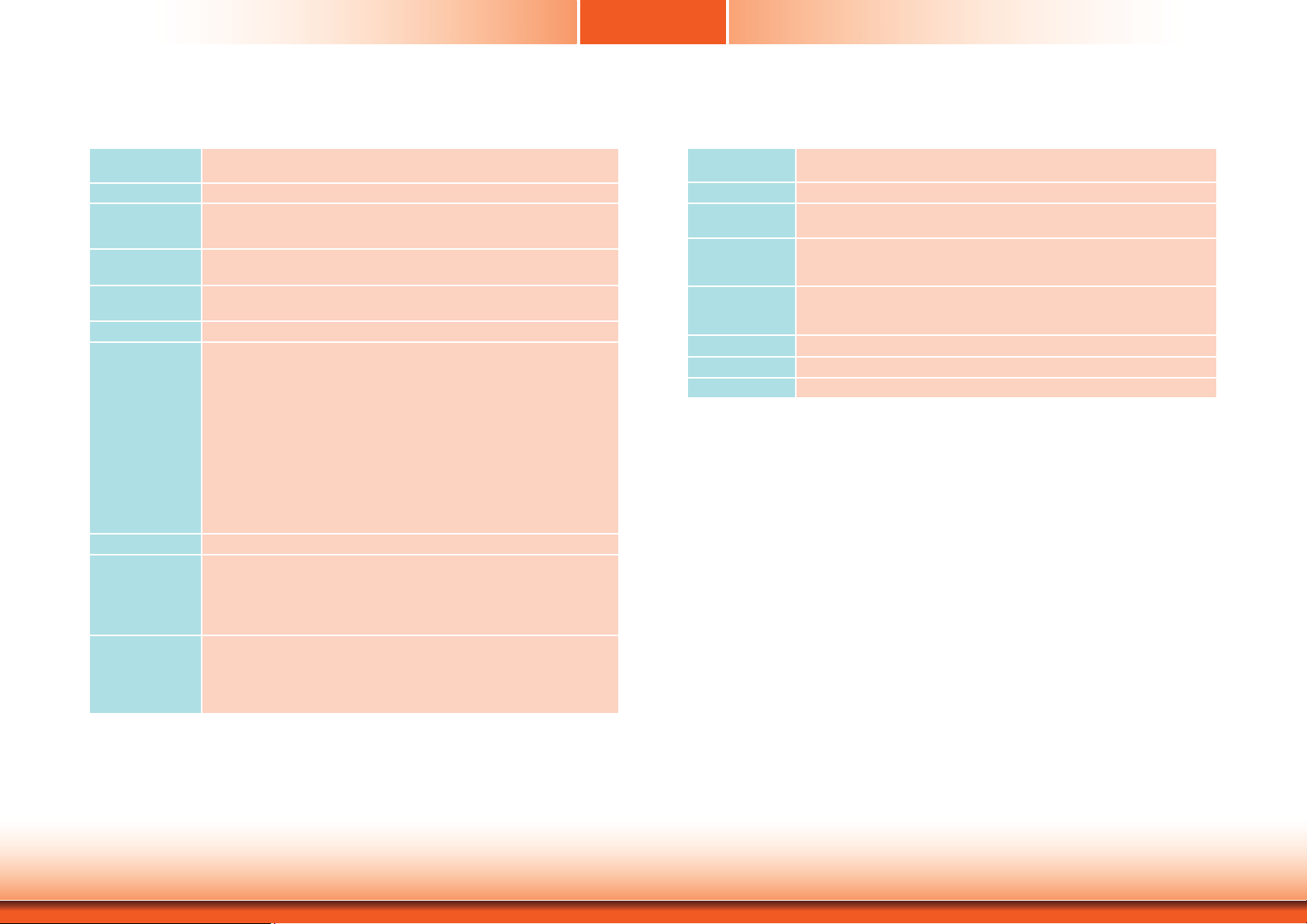
Specifications
Chapter 1
Processor • Freescale i.MX 6 series processor
System Memory • 2GB DDR3 memory down
LCD and Touch
Screen
Storage • 1 SD card socket
Onboard LAN
Features
Audio • 2 built-in 1W speakers (left and right sides)
I/O Ports • Bottom
Power • Power input voltage: 12~36V DC-in
Expansion
Slots
Environment • Temperature
- i.MX6L: i.MX 6DualLite at 1.0GHz, two cortex-A9 cores
• 7” (1024x600) WSVGA TFT touch screen LCD
• 400 NITS
• Projected capacitive touch screen
• Supports 4GB eMMC onboard
• One Atheros AR8033 Ethernet PHY
• Supports 10Mbps, 100Mbps and 1Gbps data transmission
- 1 DB-9 RS232 serial port
- 1 HDMI port
- 1 USB Client port (Type Mini B)
- 2 USB 2.0/1.1 ports (Type A)
- 1 Line-out/Mic-in jack
- 1 2-pole terminal block DC-in
- 1 LAN port
- 8-bit GPIO 7-pole terminal block (4-bit in/ 4-bit out)
- 1 Power switch
• Side
- 2 built-in 1W speakers (left and right sides)
• Top
- 1 SD card socket
-
1 DB-9 RS232/422/485 serial port
• 1 Mini PCIe slot
- Supports PCIe and USB signals
- Supports full size Mini PCIe card
• 1 mSATA slot (Mini PCIe type)
• 1 SIM card socket
- Reserved for 3G/LTE module
- Operating: 0
- Storage: -30
• Relative Humidity
- 85% RH at 65
o
C ~ 60oC
o
C ~ 80oC
o
C
Front Panel
Protection
Construction
Mounting
Vibration • Sweep frequency: 10~500~10 Hz/1min
Shock • Operating: 3G peak acceleration (11 m sec. duration)
Dimensions • 235mm x 150mm x 43.80mm (W x H x D)
Weight •
OS Support • Android 4.3
• IP65 (Dust Tight; Water Proof protection)
• Aluminum front bezel, rugged metal housing
• Wall mount (VESA 75x75)
• Panel mount (Mounting clamp)
• Amplitude: 0.75mm
• IEC 68-2-64 compliant
• Non-operating: 10G peak acceleration (11 m sec. duration)
• IEC 68-2-64 compliant
1.26 kg
Chapter 1 Introduction
7
www.dfi .com
Page 8

Getting to Know the KS210-IMX6
Chapter 1
Side View
2 built-in 1W speakers
Speakers
It is built-in with 2 1W speakers on the left and right sides of the system.
Top View
SD COM
COM Port
Used to connect a serial device.
SD
Used to insert a SD card.
Bottom View
USB
Line-out/Mic-in
HDMI
8-bit GPIO
COM Port
Used to connect a serial device.
USB Ports
Used to connect USB 2.0/1.1 devices.
USB Client Port
Used to connect a USB device operating as a client port.
HDMI Port
Use to connect a HDMI device.
LAN Port
Used to connect the system to a local area network.
8-bit GPIO
Supports 8-bit GPIO 7-pole terminal block (4-bit in/ 4-bit out).
Line-out/Mic-in
Used to connect to a speaker or to an external microphone.
DC-in
Used to plug a power adapter.
USB Client
LAN
DC-in
COM
Power Switch
Chapter 1 Introduction
8
www.dfi .com
Page 9

Mechanical Dimensions
Chapter 1
214.60
Left View
Top View
235.00
Front View
Bottom View
75.00
75.00
40.80
150.00
Right View
102.03
96.07
90.71
75.71
41.71
29.94
24.00
14.98
0.00
0.00
5.50 5.50
28.88
45.00
50.01
58.50
73.70
75.00
117.51
104.01
101.50
87.40
119.14
136.21
145.49
173.65
185.00
97.00
59.52
39.21
26.71
17.00
190.01
Chapter 1 Introduction
Rear View
9
www.dfi .com
Page 10

Chapter 2
Chapter 2 - Installing the Devices
Connecting the Cable to the Terminal Block
Note:
The system unit used in the following illustrations may not resemble the actual one.
These illustrations are for reference only.
1. Insert the cable end of the power adapter to the terminal block. To firmly fix the cable into
the terminal block, use a screwdriver to clamp down the wires to the screw that is in the
terminal block
.
Terminal block
2. Plug the terminal block into the DC-in connector and then tighten the screws to secure the
terminal block in place.
DC-in
connector
Screws
Wire
Power adapter cable
White Wire
+ -
Black Wire
Chapter 2 Installing the Devices
10
www.dfi .com
Page 11
Chapter 2
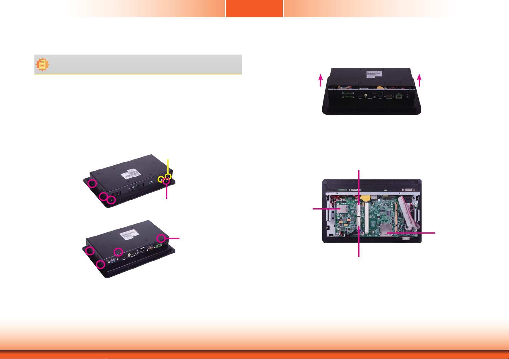
Removing the Chassis Cover
Note:
The system unit used in the following illustrations may not resemble the actual one.
These illustrations are for reference only.
1. Make sure the system and all other peripheral devices connected to it have been poweredoff.
2. Disconnect all power cords and cables.
3. The 8 mounting screws on the side and cover of the system are used to secure the cover
to the chassis and the 2 mounting screws are used to fix the COM port. Remove these
screws and then put them in a safe place for later use.
Mounting Screw (COM port)
Mounting Screw
4. After removing the mounting screws, lift the cover up.
Lift the Cover Upward
5. 1 SIM card socket, 1 SD card socket, 1 mSATA slot and 1 Mini PCIe slot are readily accessible after removing the chassis cover.
Mini PCIe Slot
SIM card socket
Chapter 2 Installing the Devices
SD card socket
Mounting Screw
mSATA Slot
11
www.dfi .com
Page 12

Chapter 2
Installing the microSD Card and the Qseven Module
Note:
The system unit used in the following illustrations may not resemble the actual one.
These illustrations are for reference only.
1. The microSD socket is located on the Qseven module.
microSD socket
Qseven module
2. Insert a microSD card into the microSD socket on the Qseven module.
microSD card
3. Note the key on the MXM connector. The key ensures that the Qseven module with a microSD card in the socket can be plugged into the connector in one direction only.
MXM connector
4. Grasp the Qseven module by its edges, insert it into the carrier board, and you will hear a
distinctive¨click¨ which indicates that the Qseven module is correctly locked into the position.
microSD socket
Chapter 2 Installing the Devices
Qseven module
12
www.dfi .com
Page 13

Chapter 2
5. Press down the Qseven module with a microSD card in the socket and use mounting
screws to fix it on place.
Mounting screw
Installing the SIM Card
Note:
The system unit used in the following illustrations may not resemble the actual one.
These illustrations are for reference only.
1. The SIM card socket is located on the system board.
SIM card socket
2. Before inserting a SIM card into the socket, you have to remove mounting screws on the
speaker.
Chapter 2 Installing the Devices
Speaker
Mounting screw
13
Mounting screw
www.dfi .com
Page 14

3. Insert the SIM card into the SIM card socket, and push it to take the card out of the socket.
Speaker
SIM card
Chapter 2
Chapter 2 Installing the Devices
14
www.dfi .com
Page 15

Chapter 3 - Jumper Settings
Jumper Settings - System Board
Panel Power Select
JP2
5
1
3
6
4
2
1-2 On: +12V 3-4 On:+5V_standby
5
1
3
6
4
2
5
1
3
6
4
2
5-6 On: +3V_standby
(default)
Chapter 3
COM RS232/UART5 Select
JP12
JP11
132
1-2 On:
RS232 (default)
132
2-3 On: UART5
JP11 and JP12 are used to configure the COM port to RS232 (default) or UART5.
Important:
You need to set JP11 and JP12 simultaneously.
JP2 is used to select the power supplied with the LCD panel.
Important:
Before powering-on the system, make sure that the power settings of JP2 match the
LCD panel’s specification. Selecting the incorrect voltage will seriously damage the
LCD panel.
Chapter 3 Jumper Settings
15
www.dfi .com
Page 16

Chapter 3
COM 1/COM 2 RS232/422/485 Select
COM 1:
RS232/422/485
9
COM 1
JP4
JP6
COM 2:
RS232/422/485
COM 2
JP4 (for COM 1) and JP6 (for COM 2) are used to configure the COM ports to RS232, RS422
(Full Duplex) or RS485. The pin functions of COM ports will vary according to jumpers’ setting.
21
4
1-2 On: RS232
2
(default)
3
1
5
6
9
RI-
CTSDSRDTR-
RTSGND
TXD
RXD DCD-
21
RS232
TD
RD
DTR-
GND
DCD-
2345
1
6789
RI-
RTS-
CTS-
DSR-
RS232
JP4 (for COM 1)/JP6 (for COM 2)
5
6
4
3
2
3-4 On: RS422
Full Duplex
1
COM 1
9
NC.
NC.NC.
NC.NC.
TXD+TXD-
RXD- RXD+
21
RS422
Full Duplex
COM 2
RXD+
TXD+
RXD-
TXD-
N.C.
12345
6789
N.C.
N.C.
N.C.
N.C.
RS422
Full Duplex
5
6
4
3
2
1
5-6 On: RS485
9
NC.
NC.
NC.
NC.NC.
TXDNC.
DATA- DATA+
21
RS485
DATA-
N.C.
N.C.
N.C.
DATA+
12345
6789
N.C.
N.C.
N.C.
N.C.
RS485
Chapter 3 Jumper Settings
16
www.dfi .com
Page 17

Chapter 3
Touch Panel Power Select
JP3
132
1-2 On:
+3V_standby
132
2-3 On: +5V_standby
(default)
Dimming Mode Select
JP10
132
1-2 On:
PWM Mode (default)
132
2-3 On:
Voltage Mode
JP3 controls the power level of the touch panel IC.
Chapter 3 Jumper Settings
JP10 allows you to select the mode for the lightness control of the LVDS panel.
Important:
You need to refer to your panel’s user guide to determine the type of mode (PWM or
Voltage) most appropriate for your panel.
17
www.dfi .com
Page 18

Chapter 3
LCD/Inverter Power Select
JP5
5
1
3
6
4
2
1-2 On: +12V 3-4 On:+5V_standby
5
3
6
4
(default)
Download Mode Select
132
1-2 On: Serial
Download Mode
JP9
2-3 On: Normal Boot
(default)
5
1
1
2
5-6 On: +3V_standby
3
JP9 allows you to select the download mode for the serial port to update the firmware and OS.
6
4
2
132
JP5 is used to select the power level of the LCD/inverter power connector.
Chapter 3 Jumper Settings
18
www.dfi .com
Page 19

Chapter 3
Line-out/Mic-in Select
1
5
JP7 1-2, 3-4, 5-6 On:
Line-out
JP7 and JP8 allow you to select the audio function. When pins 1-2, 3-4, and 5-6 are set to On,
JP7 is applied for the Line-out function and JP8 is used for the Mic-in function.
3
2
4
JP7 JP8
JP8 1-2, 3-4, 5-6 On:
Mic-in (default)
6
Jumper Setting - Qseven Module
Boot Device Select
Switch
1 Off, 2 Off, 3 On, 4 On:
eMMC
1 Off, 2 Off, 3 On, 4 Off:
uSD
1 On, 2 On, 3 Off, 4 On:
SPI3 on board SPI
1 On, 2 Off, 3 Off, 4 On:
SPI1 on carrier board
Chapter 3 Jumper Settings
Switch is designed to select the device to boot the system.
19
www.dfi .com
Page 20

Chapter 4 - Ports and Connectors
Top Panel I/O Ports
SD COM
The top panel I/O ports consist of the following:
• 1 SD card socket
• 1 COM port
Chapter 4
SD Card Socket
SD Card Socket
SD Card Socket
Chapter 4 Ports and Connectors
This expansion port is used to insert a Secure Digital Input/Output (SDIO) device. Aside from
storing data files, an SDIO card is also capable of storing powerful software applications.
20
www.dfi .com
Page 21

Chapter 4
Serial (COM) Port
COM 2:
RS232/422/485
The serial COM port is RS232 asynchronous communication port with 16C550A-compatible
UARTs that can be used with modems, serial printers, remote display terminals, and other serial devices.
The system unit is equipped with 1 onboard serial port at the top side. JP6 is used to configure the COM port 2 to RS232, RS422 (Full Duplex) or RS485. The pin functions of the COM
port will vary according to the jumper’s setting.
JP6
Side Panel I/O Ports
2 built-in 1W speakers
The side panel I/O ports consist of the following:
• 2 built-in 1W speakers (left and right sides)
Built-in Speakers
4
1-2 On: RS232
1
2
(default)
TD
RD
DCD-
2345
3
1
DTR-
GND
5
6
6789
RI-
RTS-
CTS-
DSR-
RS232
Chapter 4 Ports and Connectors
5
6
4
2
3-4 On: RS422
Full Duplex
3
1
COM 2
RXD+
TXD+
RXD-
TXD-
N.C.
12345
6789
N.C.
N.C.
N.C.
N.C.
RS422
Full Duplex
4
3
2
1
5
6
5-6 On: RS485
DATA-
N.C.
N.C.
DATA+
12345
6789
N.C.
N.C.
N.C.
N.C.
RS485
N.C.
1
2
AMP_L
AOUT_L+
AOUT_L-
AMP_R
2
AOUT_R+
AOUT_R-
The amplify left and right connectors which have amplifying features are used to connect
external speakers.
21
1
www.dfi .com
Page 22

Chapter 4
Bottom Panel I/O Ports
Line-out/Mic-in
8-bit GPIO
The bottom panel I/O ports consist of the following:
• 1 RS232 COM port
• 1 HDMI port
• 1 USB Client port (Type Mini B)
• 2 USB 2.0/1.1 ports (Type A)
• 1 Line-out/Mic-in jack
• 1 DC-in terminal block
• 1 RJ45 LAN port
• 8-bit GPIO
• 1 Power switch
HDMI
USB Client
USB
LAN
COM
DC-in
Power Switch
Serial (COM) Port
DCD-TDRD
DTR-
COM
12345
COM:
RS232 or UART5
6789
The system unit is equipped with one onboard serial COM port at the bottom side. This COM
port is fixed at RS232 or UART5 via the setting of JP11 and JP12 which must be set simultaneously.
GND
RI-
CTS-
RTS-
DSR-
Chapter 4 Ports and Connectors
The serial COM port is RS232 asynchronous communication port with 16C550A-compatible
UARTs that can be used with modems, serial printers, remote display terminals, and other serial devices.
Important:
You need to set JP11 and JP12 simultaneously.
22
www.dfi .com
Page 23

Chapter 4
HDMI Port
HDMI
The HDMI port which carries both digital audio and video signals is used to connect a LCD
monitor or digital TV that has the HDMI port.
USB Client Port
USB Client
The shape of the mini USB port is smaller than the standard one and is a device operating as
a client port.
Chapter 4 Ports and Connectors
23
www.dfi .com
Page 24

Chapter 4
USB Ports
USB 2.0
USB 1
USB 0
The USB device allows data exchange between your computer and a wide range of simultaneously accessible external Plug and Play peripherals. The system unit is equipped with two onboard USB 2.0 ports (USB 0-1) at the bottom side.
Audio
Line-out/Mic-in
The system unit is equipped with 1 audio jack to operate as a line-out jack or a mic-in jack.
A jack is a one-hole connecting interface for inserting a plug. Being a line-out jack, this jack
is used to connect a headphone or external speakers. Being a mic-in jack, this jack is used to
connect to the center and subwoofer speakers of the audio system.
Chapter 4 Ports and Connectors
24
www.dfi .com
Page 25

Chapter 4
12~36V DC-in
DC-in
This jack is considered a low power solution. Connect a DC power cord to this jack. Use a
power adapter within 12~36V DC output voltage. (We only provide 12V power adapter in the
optional package contents.) Using a voltage out of the range 12~36V may fail to boot the system or cause damage to the system board.
RJ45 LAN Port
LAN
The onboard RJ45 LAN port allows the system board to connect to a local area network by
means of a network hub.
Chapter 4 Ports and Connectors
25
www.dfi .com
Page 26

Chapter 4
8-bit GPIO
8 14
17
The 8-bit Digital I/O (4-bit input and 4-bit output) connector provides powering-on function to
external devices that are connected to these connectors. The pin functions of the digital I/O
connector are listed below:
Pins Function Pins
DIO_OUT-1
1
DIO_IN-1
2
DIO_OUT-2
3
DIO_IN-2
4
DIO_OUT-3
5
DIO_IN-3
6
DIO_OUT-4
7
8
9
10
11
12
13
14
DIO_IN-4
DIO_OUT-5
DIO_IN-5
DIO_OUT-6
DIO_IN-6
DCDC_5V_BB
GND
Function
I/O Connectors
LVDS LCD Panel Connector
40
39
LVDS LCD Panel
The system board allows you to connect a LCD Display Panel by means of the LVDS LCD panel
connector transmitting video signals and power from the system board to the LCD Display
Panel.
Refer to the next page for the pin functions of the connector.
Jumper Settings
Refer to the “Jumper Settings” section in chapter 3 for settings relevant to the LVDS LCD
panel.
Note:
DFI board's LVDS connector: Hirose DF13-40DP-1.25V(91)/40P/1.25mm; cable side
connector: Hirose DF13-40DS-1.25C.
2
1
Chapter 4 Ports and Connectors
26
www.dfi .com
Page 27

Chapter 4
The table below illustrates the pin functions of the LVDS LCD Panel connector:
Pins Function Pins Function
1
GND
3
LVDS1_Out3+
LVDS1_Out3-
5
GND
7
LVDS1_Out2+
9
LVDS1_Out2-
11
GND
13
LVDS1_Out1+
15
LVDS1_Out1-
17
GND
19
LVDS1_Out0+
21
LVDS1_Out0-
23
GND
25
LVDS1_CLK+
27
LVDS1_CLK-
29
GND
31
TP_INT
33
TP_VDD
35
Backlight Power
37
Backlight Power
39
GND
2
LVDS0_Out3+
4
6 LVDS0_Out3-
8 GND
10 LVDS0_Out2+
12 LVDS0_Out2-
14 GND
16 LVDS0_Out1+
18 LVDS0_Out1-
20 GND
22 LVDS0_Out0+
24 LVDS0_Out0-
26 GND
28 LVDS0_CLK+
30 LVDS0_CLK-
32 GND
34 TP_SCL
36 TP_SDA
38 Dimming
40 Panel Power
FlexCAN Connector
FlexCAN
9
N.C
N.C
N.C
N.C
CAN_LO
The CAN controller performs communication in accordance with the BOSCH CAN Protocol Version 2.0B Active1 (standard format and extended format). The bit rate can be programmed to
a maximum of 1Mbit/s. To connect the CAN controller module to the FlexCAN connector, it is
necessary to add transceiver hardware.
When communicating in a CAN network, individual message objects are configured. The message objects and the identifier masks for the receive filter for the received messages are
stored in the message RAM.
Controller Area Network is a message based protocol designed specifically for automotive applications but now is also used in other areas such as industrial automation and medical equipment.
N.C
GND
CAN_HI
N.C
12
Chapter 4 Ports and Connectors
27
www.dfi .com
Page 28

Chapter 4
Expansion Slots
SIM Card Socket
(supports PCIe and USB signals)
(Supports mSATA signal)
Mini PCIe Slot
The Mini PCIe socket is used to install a Mini PCIe card. Mini PCIe card is a small form factor
PCI card with the same signal protocol, electrical definitions, and configuration definitions as
the conventional PCI.
SIM Card Socket
The SIM slot on the system board is used to insert a SIM card.
Mini PCIe
Mini PCIe
LEDs
SD LED
Power LED
SD Card Socket
SD LED
The SD LED will light when the SDIO card is inserted into the SD card socket.
Power LED
The power LED indicates that there is power on the system board. Power-off the PC and then
unplug the power cord prior to installing any devices. Failure to do so will cause severe damage to the system board and components.
SD Card Socket
This expansion port is used to insert a Secure Digital Input/Output (SDIO) device. Aside from
storing data files, an SDIO card is also capable of storing powerful software applications.
Chapter 4 Ports and Connectors
28
www.dfi .com
Page 29

Chapter 4
RTC Battery
RTC
2
+3.3V
GND
1
Battery
Battery
Connect to the battery connector
Power Switch
Power
2
Power_Enable
GND
Power Switch
The power switch is used to power on or power off the system.
Switch
1
The RTC Battery powers the real-time clock and CMOS memory. It is an auxiliary source of
power when the main power is shut off.
Safety Measures
• Danger of explosion if battery incorrectly replaced.
• Replace only with the same or equivalent type recommend by the manufacturer.
• Dispose of used batteries according to local ordinance
.
Chapter 4 Ports and Connectors
29
www.dfi .com
Page 30

Chapter 4
Serial (COM) Port
9
COM 1:
RS232/422/485
12
The system board is equipped with a 9-pin connector for connecting an external serial COM
port (COM 1). COM port 1 will vary according to JP4’s setting.
The serial COM port is RS232 asynchronous communication port with 16C550A-compatible
UARTs that can be used with modems, serial printers, remote display terminals, and other serial devices. To connect COM 1, please refer to the following description. The serial port may
be mounted on a card-edge bracket. Install the card-edge bracket to an available slot at the
rear of the system chassis then insert the cable connector to the 9-pin connector. Make sure
the colored stripe on the ribbon cable is aligned with pin 1 of the connector.
JP4
MXM Connector
MXM
The MXM connector is used to interface the carrier board with a Qseven board. Refer to the
table in the following pages for the pin functions of the MXM connector.
4
2
1-2 On: RS232
(default)
3
1
5
6
9
RI-
CTSDSRDTR-
RTSGND
TXD
RXD DCD-
21
RS232
Chapter 4 Ports and Connectors
5
6
4
3-4 On: RS422
3
2
1
Full Duplex
COM 1
9
NC.
NC.NC.
NC.NC.
TXD+TXD-
RXD- RXD+
21
RS422
Full Duplex
5
6
4
3
2
1
5-6 On: RS485
9
NC.
NC.
NC.
NC.NC.
TXDNC.
DATA- DATA+
21
RS485
30
www.dfi .com
Page 31

Chapter 4
Pin Signal Pin Signal
1GND 2GND
3 GBE_MDI3- 4 GBE_MDI25 GBE_MDI3+ 6 GBE_MDI2+
7 GBE_LINK100# 8 GBE_LINK1000#
9 GBE_MDI1- 10 GBE_MDI011 GBE_MDI1+ 12 GBE_MDI0+
13 GBE_LINK# 14 GBE_ACT#
15 16 SUS_S5#
17 WAKE# 18 SUS_S3#
19 SUS_STAT# 20 PWRBTN#
21 SLP_BTN# 22 LID_BTN#
23 GND 24 GND
25 GND 26 PWGIN
27 BATLOW# 28 RSTBTN#
29 SATA0_TX+ 30
31 SATA0_TX- 32
33 SATA0_ACT# 34 GND
35 SATA0_RX+ 36
37 SATA0_RX- 38
39 GND 40 GND
41 BIOS_DISABLE#/BOOT_ALT# 42 SDIO_CLK
43 SDIO_CD# 44 SDIO_LED
45 SDIO_CMD 46 SDIO_WP
47 SDIO_PWR# 48 SDIO_DAT1
49 SDIO_DAT0 50 SDIO_DAT3
51 SDIO_DAT2 52 SDIO_DAT5
53 SDIO_DAT4 54 SDIO_DAT7
55 SDIO_DAT6 56 RSVD
57 GND 58 GND
59 I2S_TXFS 60 SMB_CLK
61 I2S_CLK 62 SMB_DAT
63 I2S_TXC 64 SMB_ALERT#
65 I2S_RXD 66 I2C_CLK
67 I2S_TXD 68 I2C_DAT
69 70 WDTRIG#
71 72 WDOUT
73 GND 74 GND
75 76
77 78
79 80 USB_4_5_OC#
81 82 USB_P483 84 USB_P4+
85 USB_2_3_OC# 86 USB_0_1_OC#
87 USB_P3- 88 USB_P289 USB_P3+ 90 USB_P2+
91 USB_CC 92 USB_ID
93 USB_P1- 94 USB_P095 USB_P1+ 96 USB_P0+
97 GND 98 GND
99 LVDS_A0+ 100 LVDS_B0+
Pin Signal Pin Signal
101 LVDS_A0- 102 LVDS_B0103 LVDS_A1+ 104 LVDS_B1+
105 LVDS_A1- 106 LVDS_B1107 LVDS_A2+ 108 LVDS_B2+
109 LVDS_A2- 110 LVDS_B2-
LVDS_PPEN
111
LVDS_A3+
113
LVDS_A3-
115
GND
117
LVDS_A_CLK+
119
LVDS_A_CLK-
121
LVDS_BLT_CTRL/GP_PWM_OUT0
123
LVDS_DID_DAT/GP_I2C_DAT
125
LVDS_DID_CLK/GP_I2C_CLK
127
CAN0_TX
129
TMDS_CLK+
131
TMDS_CLK-
133
GND
135
TMDS_LANE1+
137
TMDS_LANE1-
139
GND
141
TMDS_LANE0+
143
TMDS_LANE0-
145
GND
147
TMDS_LANE2+
149
TMDS_LANE2-
151
HDMI_HPD#
153
PCIE_CLK_REF+
155
PCIE_CLK_REF-
157
GND
159
161 162
163 164
GND
165
167 168
169 170
UART_TXD
171
173 174
175 176
UART_RXD
177
PCIE0_TX+
179
PCIE0_TX-
181
GND
183
185 186
187 188
189 190
191 192
VCC_RTC
193
195 196
GND
197
SPI_MOS1
199
LVDS_BLEN
112
114 LVDS_B3+
116 LVDS_B3-
GND
118
LVDS_B_CLK+
120
LVDS_B_CLK-
122
RSVD
124
LVDS_BLC_DAT
126
LVDS_BLC_CLK
128
CAN0_RX
130
132
134
GND
136
138
140
GND
142
144
146
GND
148
HDMI_CTRL_DAT
150
HDMI_CTRL_CLK
152
154
PCIE_WAKE#
156
PCIE_RST#
158
GND
160
GND
166
UART_RTS
172
UART_CTS
178
PCIE0_RX+
180
PCIE0_RX-
182
GND
184
194
GND
198
SPI_CS0#
200
Chapter 4 Ports and Connectors
31
www.dfi .com
Page 32

Pin Signal Pin Signal
SPI_MOS0
201
203
205
207
209
211
213
215
217
219
221
223
225
227
229
SPI_SCK
5V_SB
MFG_NC0
MFG_NC1
VCC (+5V)
VCC (+5V)
VCC (+5V)
VCC (+5V)
VCC (+5V)
VCC (+5V)
VCC (+5V)
VCC (+5V)
VCC (+5V)
VCC (+5V)
202
204
206
208
210
212
214
216
218
220
222
224
226
228
230
MFG_NC4
5V_SB
MFG_NC2
MFG_NC3
VCC (+5V)
VCC (+5V)
VCC (+5V)
VCC (+5V)
VCC (+5V)
VCC (+5V)
VCC (+5V)
VCC (+5V)
VCC (+5V)
VCC (+5V)
Chapter 4
Chapter 4 Ports and Connectors
32
www.dfi .com
Page 33

Chapter 5 - Mounting Options
Wall Mount
Chapter 5
3. Attach the other bracket (wall mount bracket 2) to the rear of the Panel PC.
Note:
The system unit used in the following illustrations may not resemble the actual one.
These illustrations are for reference only.
The wall mount kit includes the following:
• 2 Wall mount brackets
• Bracket screws
Wall mount bracket 1 Wall mount bracket 2
1. Select a place on the wall where you will mount the Panel PC.
2. Use the provided mounting screws to attach “wall mount bracket 1” to the wall.
Mounting screw
Wall mount bracket 2
Hooks
4. Using the hooks on “bracket 2”, slide the Panel PC to “bracket 1”.
Wall mount bracket 2
Wall mount bracket 1
5. Tighten the screw to hold the assembly in place.
Chapter 5 Mounting Options
Mounting screw
Mounting screw
Wall mount bracket 1
33
www.dfi .com
Page 34

Chapter 5
Panel Mount
Note:
The system unit used in the following illustrations may not resemble the actual one.
These illustrations are for reference only.
The panel mounting kit includes the following:
• 4 mounting clamps
1. Select a place on the panel where you will mount the Panel PC.
2. Cut out a shape on the panel that corresponds to the Panel PC’s rear dimensions
(217.60mm x 128.60mm).
Chapter 5 Mounting Options
128.60
217.60
3. Stick the poron foam on the rear panel.
Poron foam
Poron foam
34
www.dfi .com
Page 35

Chapter 5
4. Slide the Panel PC through the hole until it is properly fi tted against the panel.
5. Position the mounting clamps along the rear edges of the Panel PC, fi tting them into the slits
that are around the Panel PC.
Mounting
clamp
White plastic
cap
6. The fi rst and second clamps must be positioned and secured diagonally prior to mounting the
rest of the clamps. Tighten the clamp’s screw using an electric screwdriver until the white
plastic cap touches the panel. Do not over tighten the screws to prevent damaging the Panel
PC. The illustration below shows all clamps properly mounted.
Slit for mounting
the clamp
Panel wall
128.60
217.60
Chapter 5 Mounting Options
Note:
The maximum thickness of your panel’s opening should be 10 mm. Be sure to route
or trim down the thick wall to 10 mm or slightly less for the clamps to recess and
be compatible with your wall or enclosure.
35
www.dfi .com
Page 36

Chapter 6 - BSP Installation Guide
1. Preparing the Working Environment for the
BSP installation
• 1 Windows XP/7 32-bit/64-bit
• 1 Putty.exe.
• 1 FS700
• 1 RS232 cable
Chapter 6
2. Installing the MFG Tool
1. Set the jumper Download Mode Select (JP19) to 1-2: On.
• 1 Mini USB cable
• MFG Tool
- FS700 Android DualLite/Solo:
C:\MFGTools\FS700_android_DualLite_Solo
- FS700 LTIB DualLite/Solo:
C:\MFGTools\FS700_LTIB_DualLite_Solo
- FS700 Android Quad/ Dual:
C:\MFGTools\FS700_android_Quad_Dual
- FS700 LTIB Quad/ Dual:
C:\MFGTools\FS700_LTIB_Quad_Dual
Download Mode Select
36
www.dfi .comChapter 6 BSP User Guide
Page 37

Chapter 6
2. Connect the Mini USB cable and the RS232 cable, and then power-on the system.
3. Double check if the device is correctly installed.
3. Burn Bin files and copy Bin files into the content of MFG Tool.
• Android: (1)u-boot.bin (2)boot.img (3)system.img (4)recovery.img
• Path: x:\FS700_android_DualLite_Solo\Profiles\MX6DL Linux Update\OS Firmware\files\
android
• Path : x:\FS700_android_Quad_Dual\Profiles\MX6Q Linux Update\OS Firmware\files\android
• LTIB : (1)u-boot.bin (2)uImage (3)rootfs.tar.bz2
• Path: x:\FS700_LTIB_DualLite_Solo\Profiles\MX6DL Linux Update\OS Firmware\files
• Path : x:\FS700_LTIB_Quad_Dual\Profiles\MX6Q Linux Update\OS Firmware\files
4. Execute Putty.exe and MfgTool. exe.
Putty.exe
37
www.dfi .comChapter 6 BSP User Guide
Page 38

Putty.exe
Chapter 6
5. Click “Start“ to burn the file.
38
www.dfi .comChapter 6 BSP User Guide
Page 39

Chapter 6
6. After the burning is done, click “Stop“ and shut down FS700. Set to the “Start Mode“ and
then reboot the device into the OS.
3. How to Use the ADB Tool
1. Install the driver while booting Android.
Path: C:\ADB\adb_usb_driver
39
www.dfi .comChapter 6 BSP User Guide
Page 40

Chapter 6
2. Check if the USB debugging in Android is ticked off. If not, click on “Settings”->”Developer
options”->“USB debugging”.
3. Prepare the ADB Tool.
• Copy the “.android“ content to windows
• Path: C:\ADB
• XP: copy the “.android“ content to C:\Documents and Settings\“Your PC logging name”
• Win7: copy the “.android“ content to C:\User\ “Your PC logging name”
4. Use the ADB Tool.
Open the “Command Prompt“ in Microsoft Windows.
40
www.dfi .comChapter 6 BSP User Guide
Page 41

Chapter 6
Enter “adb devices.“ When “0123456789ABCDEF“ appears, it means the connection is successful. The adb command can be used.
5. adb command
• Install APK --> “adb install D:\demo\APK\ ES1.4.8.9.apk”
• Close the adb service --> “adb kill-server”
• Start the adb service --> “adb start-server”
Note:
For more information about Freescale IMX6, please refer to the following website:
https://community.freescale.com/welcome
41
www.dfi .comChapter 6 BSP User Guide
 Loading...