

Page 1
KS200/202 Installation Guide
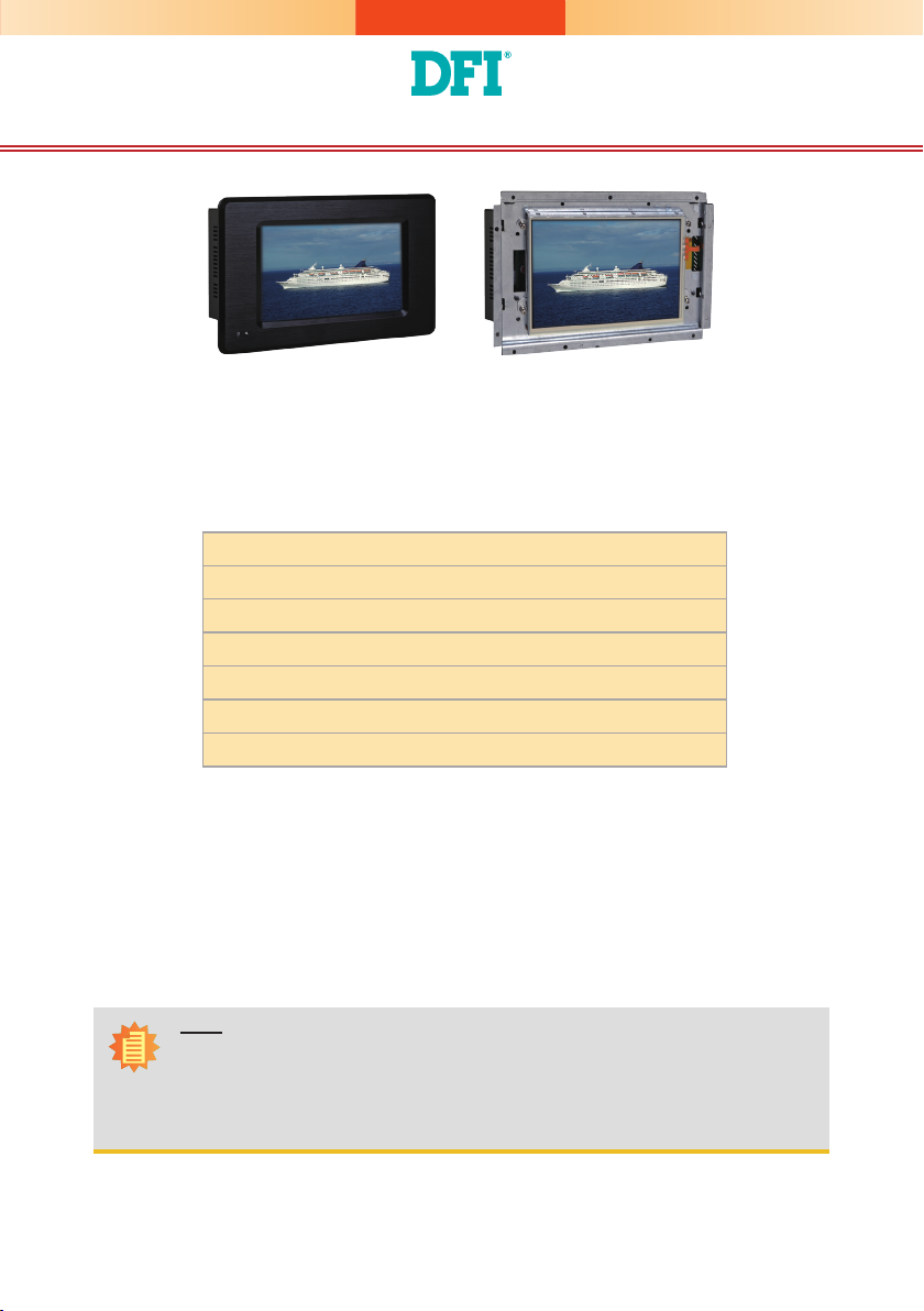
KS200 KS202
Package Contents
•
1 7" Touch Panel PC
•
1 Poron foam
•
1 24V power adapter
•
3 Terminal blocks
•
1 Quick Installation Guide
•
1 CD disk includes:
- Manual
Note:
The CD that came with the system contains an autorun screen to install drivers, utilities,
and software applications required to enhance the performance of the system and a user's
manual for your reference. Insert the CD into a CD-ROM drive. The autorun screen will
appear. If after inserting the CD, “Autorun” did not automatically start, please go directly to
the root directory of the CD and double-click “Setup”. Please install all required drivers.
DFI reserves the right to change the specications at any time prior to the product's release. For the latest revision and for a
more details of the installation process, please refer to the user's manual on the website.
www.d.com
1
Page 2
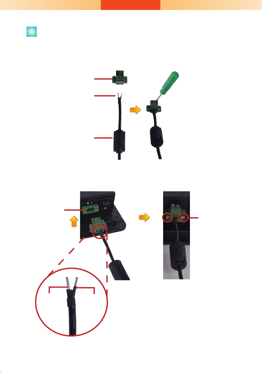
Connecting Cables to Terminal Blocks
1. Insert the cable end of the power adaptor to the terminal block. To rmly x the cable into
the terminal block, use a screwdriver to clamp down the wires to the screw that is in the
terminal block.
Terminal block
Wire
Power adapter cable
2. Plug the terminal block into the DC-in connector and then tighten the screws to secure the
terminal block in place.
DC-in
connector
Screws
White Wire
+ -
Black Wire
2
Page 3

Board Layout and Jumper Settings
DC-in
Power SW
Touch
Connector (option)
LED Connector (external)
Standby Power LED
COM 2
SP338EER1
3
1
COM2 RS232/422/485 HW/SW Select(JP7)
1
1
DDR2
128M
2 3 4 5 6
1
ON
SW4
USB 2514BI
12
10
AM3517AZCN
DDR2
128M
USB 1-2
DDR2
128M
Clear CMOS(JP1)
DDR2
128M
1
NAND Flash
LAN 1
16T245
16T245
Battery
COM 1
AIC23B
Line-out
19
20
Amplifier 2W
Connector
Touch
Connector
(default)
Reset
TOP VIEW
1
DIO
1
14
1
Android Hot Key Connector
5
1
ON
1
2 3 4 5 6
SW3
LVDS83B
1
2
LVDS LCD Panel
AVC
AVC
SD/MMC
RS232/RS422/RS485 HW/SW Select: COM 2 (JP7)
Set via Software 1-4-7-10
Set via Hardware 2-5-8-11
2-5-8-11 On
3-6-9-12 On
Boot Sequence (SW3)
MMC Boot 1-4 On, 2-3 Off
NAND Boot 1-4 Off
BOTTOM VIEW
Clear CMOS Data JP1
Normal (default) 1-2 On
Clear CMOS Data 2-3 On
RS232/RS422/RS485 Select: COM 2(SW4)
RS232 1 On, 2-3 Off
RS422 1-2 On, 3 Off
RS485 2 On, 1.3 Off
Note: If you use SW4 to select RS232/ RS422/ RS485, make
sure JP7 is set to “Set via Hardware”.
934-KS2000-0A0G
3
A23212304
 Loading...