

DFI KS070-AL, KS150-AL, KS190-AL, KS215-AL Installation Manual
KS070/150/190/215-AL Installation Guide
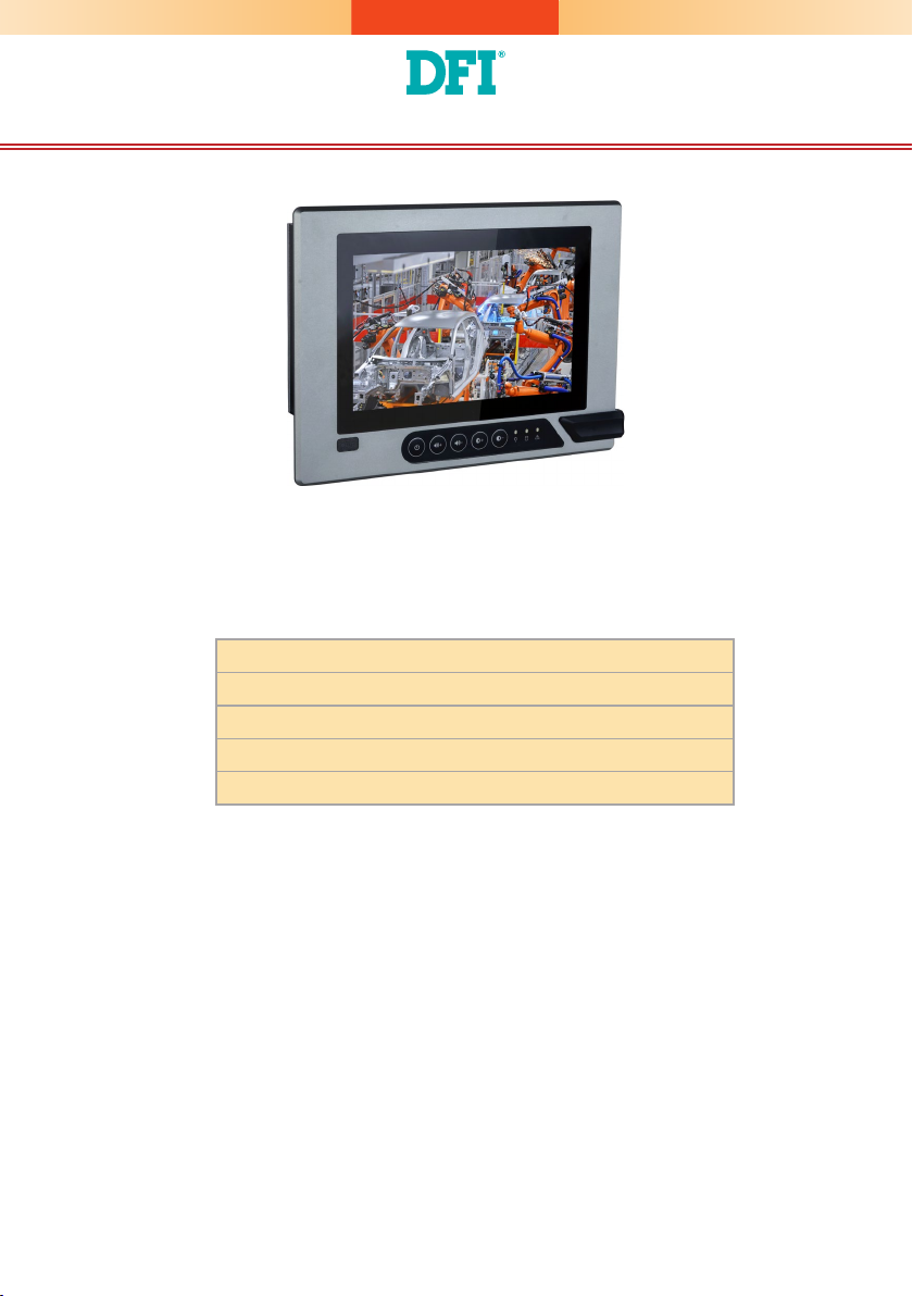
Package Contents
•
One 7", 15", 19", or 21.5" Modular Touch Panel PC
•
3-pin and 2-pin Terminal Block Connectors
•
SATA and Mini PCIe Installation Screws
•
1 DVD disk includes:
- Manual
DFI reserves the right to change the specications at any time prior to the
product's release. For the latest revision and more details of the installation
procedure, please refer to the user's manual on the website.
www.d.com
1
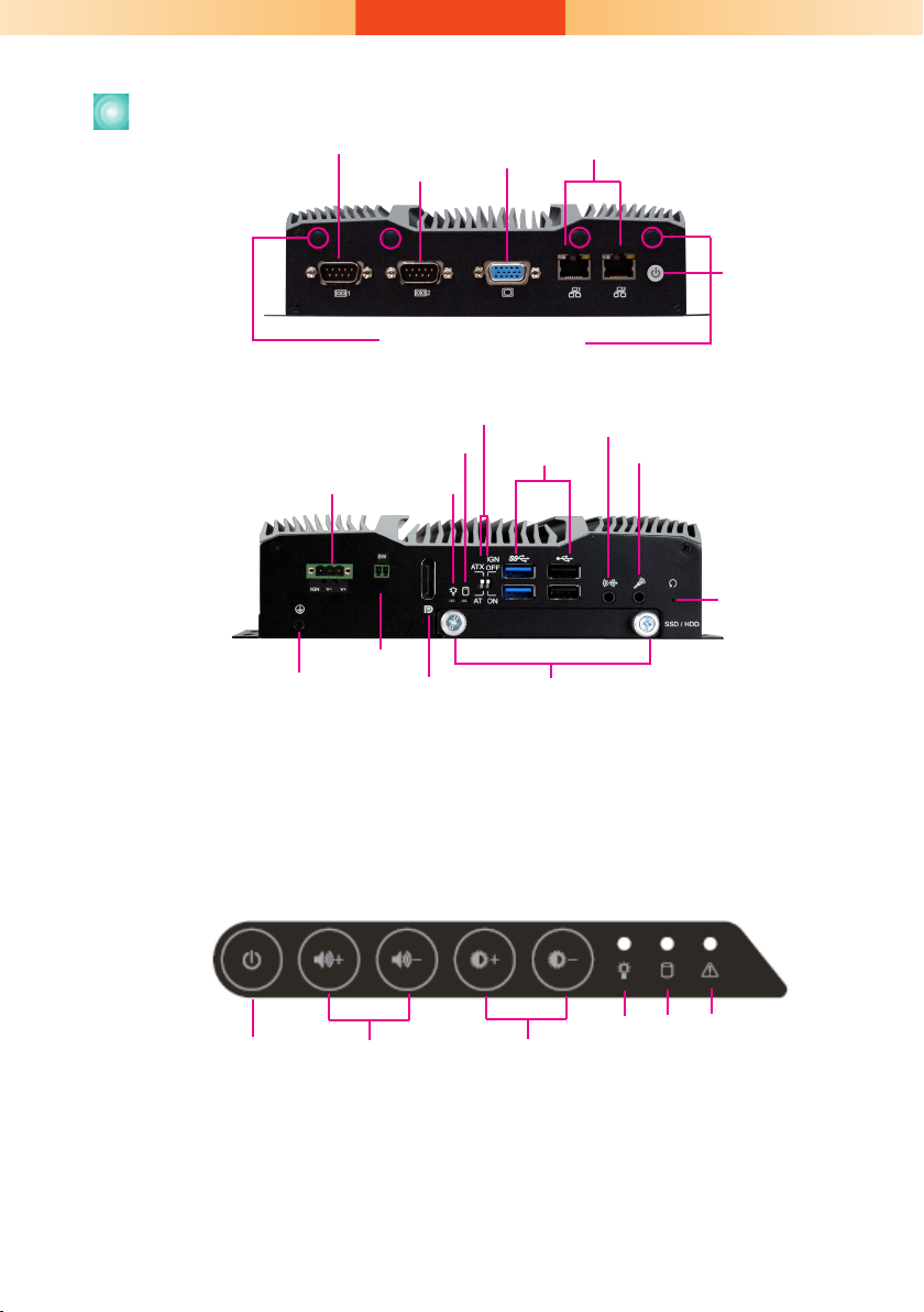
Panel
COM 1
(RS232/RS422/RS485)
(RS232/RS422/RS485)
COM 2
VGA
LAN 1 LAN 2
Top View
Power
Connector
Antenna Hole
Power Management Switch
HDD LED
Status LED
USB 3.0 USB 2.0
Line-out
Mic-in
Power Button
Bottom View
Reset Switch
Distant Switch
Grounding
Notes on Power Management Settings:
1. AT Mode: The system powers on when power is applied.
2. ATX Mode: The system powers on via the power button or the auto power-on setting in the BIOS.
3. IGN Mode: The system powers on via the ignition control with settings of on/off delay in the
BIOS, plus low-voltage protection (i.e. the system will not power on if the car battery's voltage is
below 10.5, 21V and 42V for 12V input, 24V and 48V input respectively). Note that for this mode
to work, please switch the AT/ATX mode to ATX. Also note this mode is not available for systems
with a DC-in jack (optional).
DP++
SATA Drive Bay
Front OSD Functions
Backlight or Power
on/off
Notes on OSD Settings:
1. System Power On/Off: Press the Backlight on/off button for 3 seconds.
2. Light Sensor On/Off: Press the Brightness up arrow for 3 seconds.
3. OSD Lock/Unlock: Press the Brightness down arrow for 3 seconds.
4. Both the Status LED (on the box module) and Power LED (on the front OSD) will ash when the
power on/off delay has been set in the BIOS.
Volume Control Brightness
Control
(green) (orange)
2
Power HDD Alarm LED
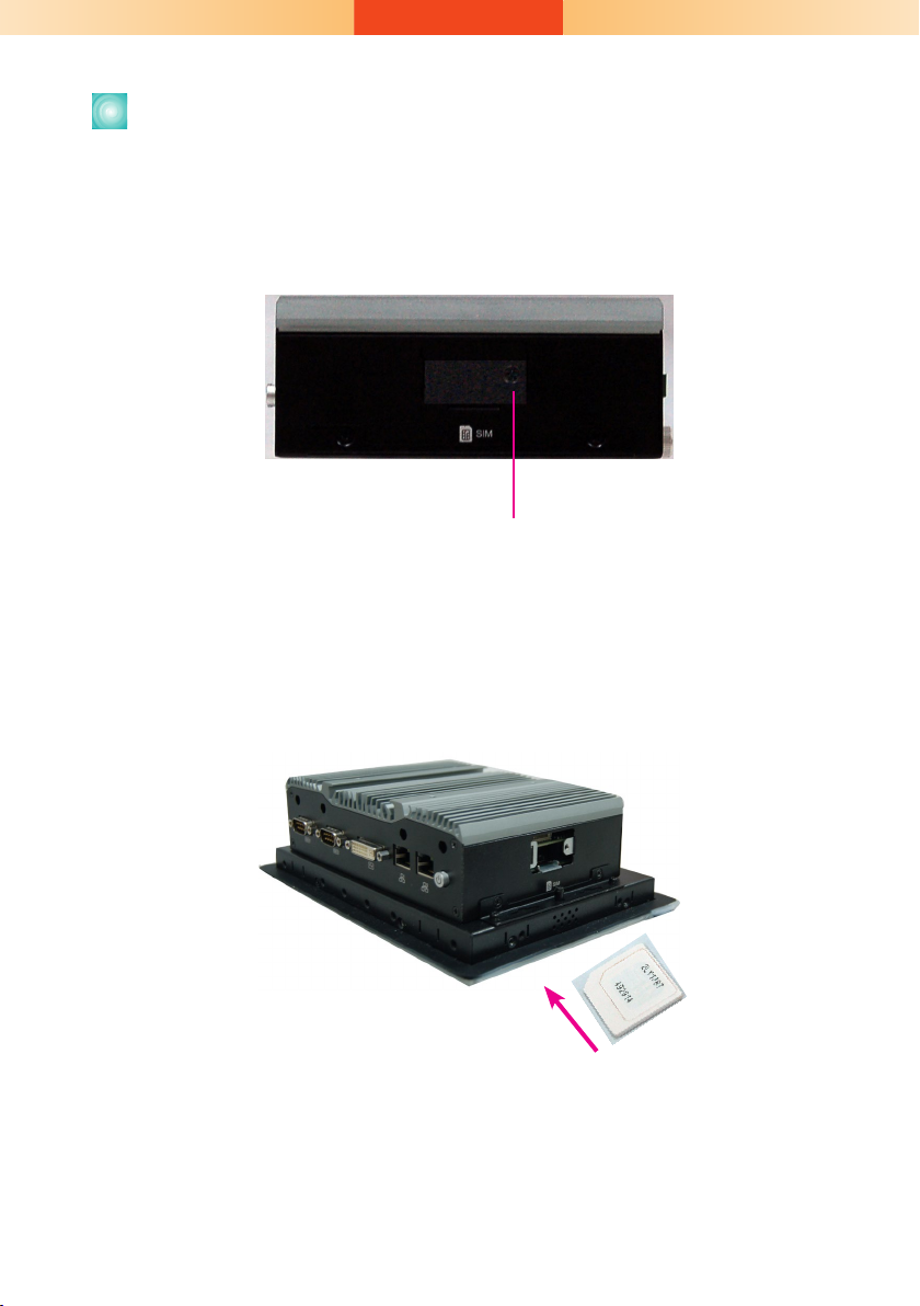
Installing a SIM Card
The SIM card socket can be accessed without opening the chassis. It is located on the side of the box module.
1. Remove the screw to open the slot.
Side View
SIM Card Slot Screw
2. Insert the SIM card into the slot. Please place the card with the IC facing down and the angled corner facing toward the socket so that it will
be in contact with the system board.
Note:
Make sure that the SIM card is inserted completely into the socket; you should feel a
force of the spring that locks the card in place. To release the card, push it inward to unlock it.
3
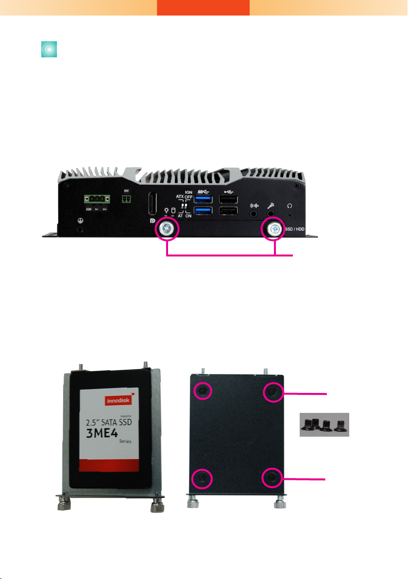
Installing a SATA Drive
The SATA drive tray can be easily accessed without opening the system.
However, the system does not support hot-swapping hard drives; turn off
the system rst.
1. Locate the drive tray on the bottom panel and open it by releasing
the thumbscrews.
SATA Drive Tray
Thumbscrew
2. Position the HDD on the drive tray and align the mounting holes of the
HDD with the mounting holes of the drive tray.
Mounting Screw
4
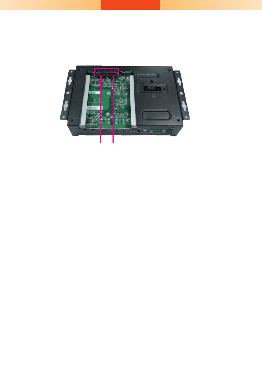
3. Slide the HDD into the drive bay by aligning the HDD's data and power
connectors with the system's SATA data and power connectors. Then
close the drive tray and secure the drive in place with the thumbscrews.
SATA Power / Data Cable
5
Removing the Chassis Cover
Installing internal components requires you to remove the chassis. Please
use the following procedure to open the chassis cover.
1. Make sure the system and all other peripheral devices connected to it
have been powered-off.
2. Disconnect all power cords and cables.
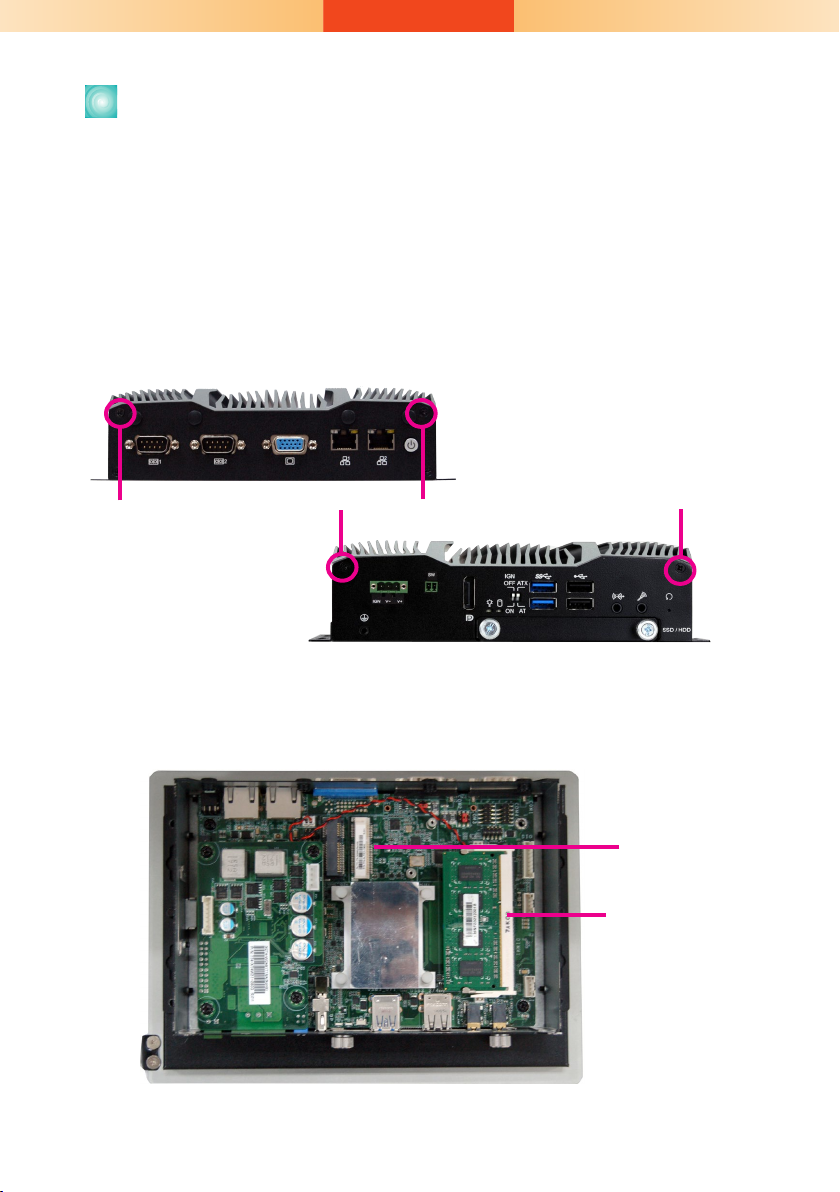
3. The 4 mounting screws on the rear side of the system are used to secure the cover to the chassis. Remove these screws and put them in a
safe place for later use.
Mounting Screw
Mounting Screw
4. Lift the cover to open the system.
5. The Mini PCIe and the SODIMM slots are readily accessible after remov-
ing the chassis cover.
Mini PCIe
Sockets
SODIMM
Socket
6
 Loading...