

Page 1
KS150/190/215-SD Installation Guide
Package Contents
•
One 15", 19", or 21.5" Modular Touch Panel PC
•
3-pin Terminal Blcok Connector
•
SATA and Mini PCIe Installation Screws
DFI reserves the right to change the specications at any time prior to the
product's release. For the latest revision and more details of the installation
procedure, please refer to the user's manual on the website.
www.d.com
1
Page 2
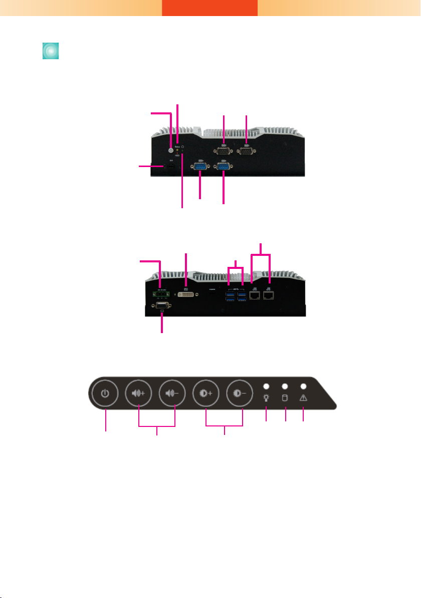
Panel
Bottom View
Power Button
Remote Power Switch
Status LED (Orange)
HDD LED (Red)
COM 2
COM 3
Reset Button
COM 1
COM 4
Top View
DC-in
Front OSD Functions (only for models with front OSD)
Backlight or Power
on/off
Notes on OSD Settings:
The front OSD is capable of controlling the system in the following ways in addition to
its explicit functions.
1. System Power On/Off: Press the Backlight on/off button for 3 seconds.
2. Light Sensor On/Off: Press the Brightness up arrow for 3 seconds.
3. OSD Lock/Unlock: Press the Brightness down arrow for 3 seconds.
4. The Alarm LED has no funtion for the KS-SD Series.
Volume
DVI-D
(DVI-I connector)
VGA
Brightness
USB 3.0
LAN 2
LAN 1
Power HDD Alarm LED
2
Page 3
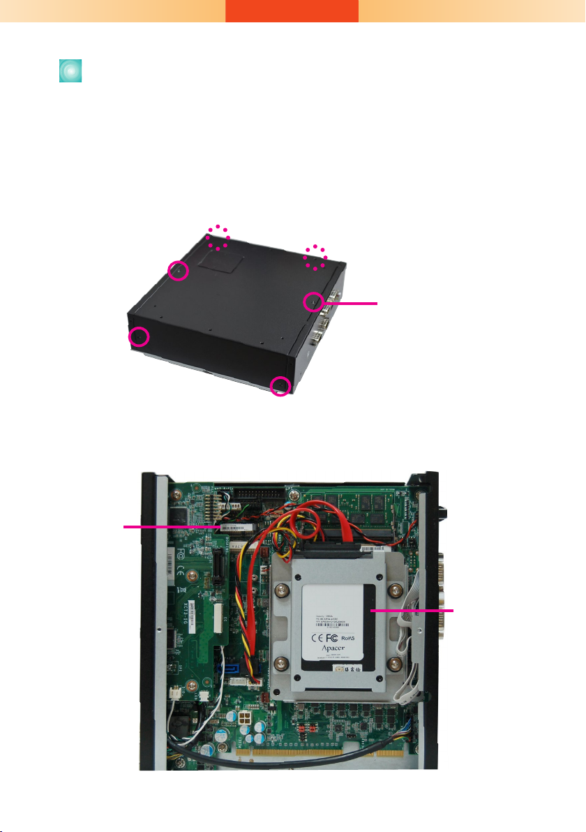
Removing the Chassis Cover
1. Make sure the system and all other peripheral devices connected to it
have been powered-off.
2. Disconnect all power cords and cables.
3. The 6 mounting screws on the rear side of the system are used to
secure the cover to the chassis. Remove these screws and put them in a
safe place for later use.
Mounting Screw
4. Lift the cover to open the system.
5. The Mini PCIe, M.2 and the SODIMM slots are readily accessible after
removing the chassis cover.
Mini PCIe
Sockets
SATA drive bay
3
Page 4
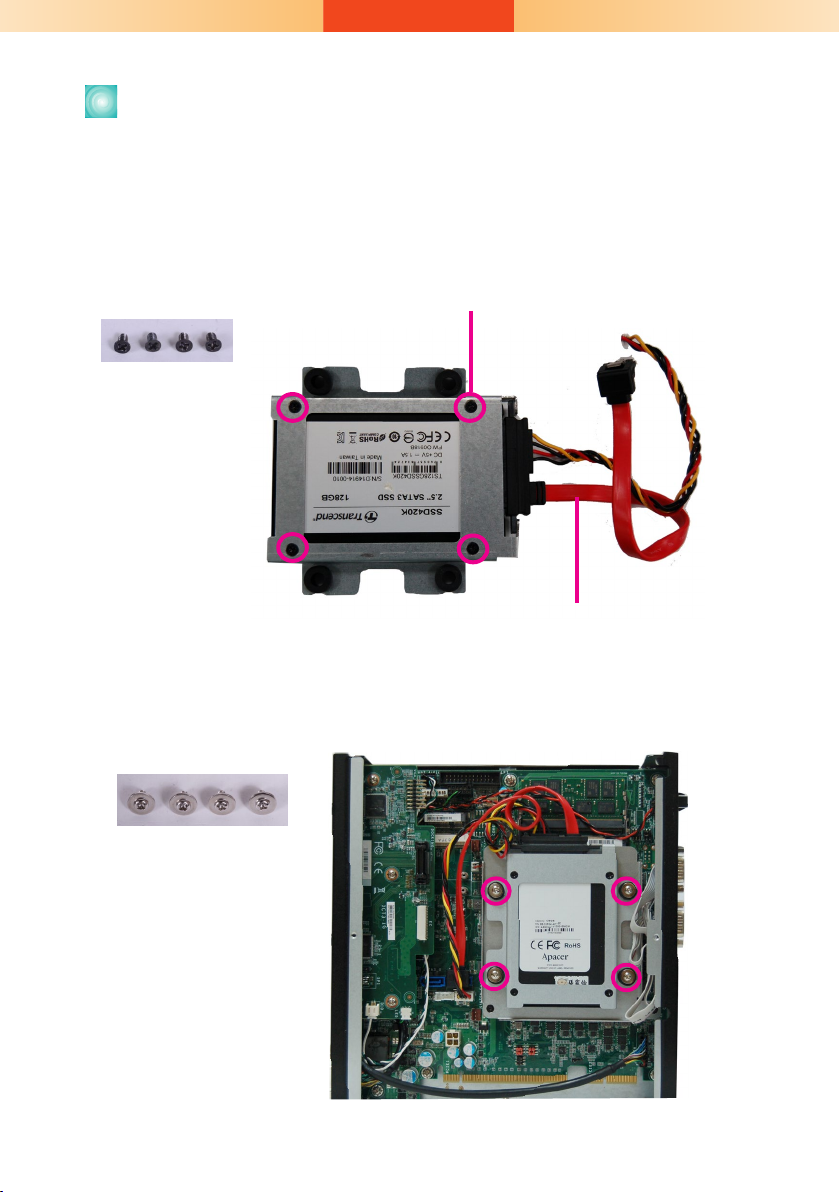
Installing a SATA Drive
The system can accommodate one SATA drive. Please use the following
procedure to install a SATA drive in the system.
1. Before installing the SATA drive, connect the SATA data/power cable
to the SATA data connector of the SATA drive. Then install the SATA
drive onto the HDD bracket with the provided mounting screws.
Mounting Screws
Mounting screws
SATA data and power cable
2. Place the SATA drive installed with the HDD bracket in the system.
Align the mounting holes on the HDD bracket with the mounting holes
on the drive bay and use the provided mounting screws to secure the
drive in place.
Mounting Screws
4
Page 5
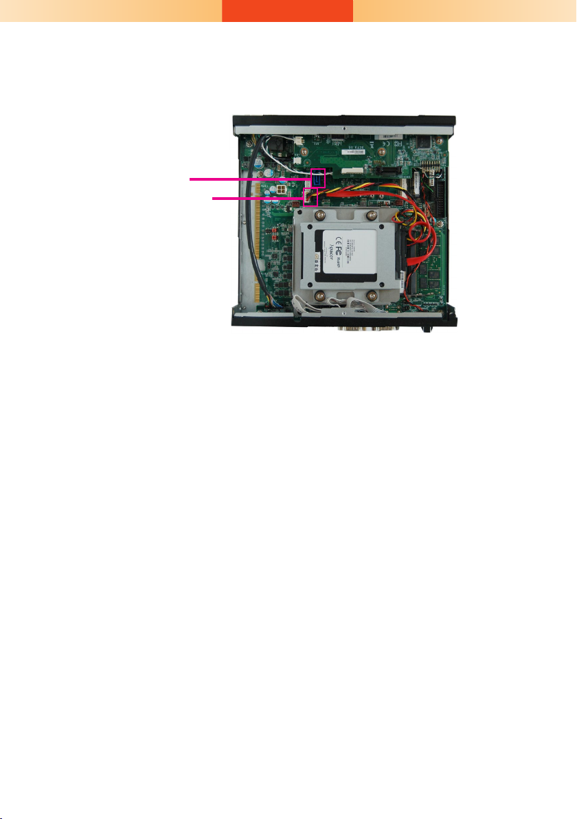
3. Connect the other end of the SATA data/power cable to the SATA data
and power connectors on the system board respectively.
SATA data connector
SATA power connector
5
Page 6

Installing a SODIMM
The system supports two DDR4 SODIMM socket. To install a memory module, grasp the memory module by its edges and align the module’s notch
with the socket’s notch; then insert the memory into the socket at an
angle and push it down until you feel a click.
Insert the memory
at an angle
SODIMM module
installed into the socket
Notes:
1. The system supports dual-channel conguration. To enable dual-channel,
populate both SODIMM sockets.
2. If installing only one memory module, please install it on the memory socket
labeled DIMM 1 (the one closer to the edge of the board).
3. The SODIMM sockets can only accept DDR4 memory modules. Please do not
install other types of memory modules.
6
Page 7

Installing a Mini PCIe or mSATA Card
The system board is equipped with 2 Mini PCIe slots: one full-size and
(PCIe/USB signals) and one half-size slot (USB/mSATA signals). Here we will
demonstrate the installation of a full-size Mini PCIe card.
1. Grasp the Mini PCIe card by its edges and align the notch in the
connector of the Mini PCIe card with the notch in the connector on the
system board.
2. Push the Mini PCIe card down and use the provided mounting screw to
secure the card on the system board.
Mounting screw
Antenna hole
7
Page 8

Important:
The bottom side of a full-size Mini PCIe module should have a component height
restriction of 0.82 mm and will sit ush against the connected half-size Mini PCIe
module if such a component is used and the half-size slot is connected with a
module.
0.82mm
8
Page 9

Assemble the Modular Panel PC
The modular panel PC comprises two parts: a box module and a panel module.
1. Take off the cover of the ADP connector. Hold the box module with its
ADP connector (female) in line with the ADP connector (male) of the
panel module. Align the box module with the panel module using the
alignment posts.
ADP
connector
cover screw
Box Module
ADP
Connector
(female)
2. Hold the box module with its ADP connector (female) in line with the
ADP connector (male) of the panel module. Align the box module with
the panel module using the alignment posts.
Alignment
Post
Note:
If the orientation of the assembly is not correct, the box module will not seat evenly on top
of the panel module, which results in some space in between them and indicates that the
ADP connectors are not engaged. When this is the case, please turn the box module the
other way around.
Panel Module
9
Page 10

3. Seat the box module on top of the panel module with the alignment
post effortlessly sliping into the designated holes on the box module.
Press to install these two modules and secure the installation with 8
mouting screws.
Mounting Screw
Alignment
Post
Mounting Screw
Box + Panel Module
10
Page 11

Mounting Options
VESA mount
The VESA-mount specifications for this device is 100 x 100 (mm).
Please use a compatible VESA mount kit that can sustain the weight
and size of this device. The VESA mount kit includes the following:
• 2 VESA mount brackets
• Bracket screws
VESA mount bracket 1
VESA mount bracket 2
1. Before starting any installation procedures, attach the poron foam to
the Panel PC.
Poron foam
2. Select a place on the wall where you will mount the Panel PC.
3. Use the provided mounting screws to attach “VESA mount bracket 1” to
the wall.
Mounting screw
VESA mount bracket 1
11
Page 12

4. The system has designed Attach the other bracket (VESA mount
bracket 2) to the rear of the Panel PC.
Thumb screw
Hooks
VESA mount bracket 2
Mounting screw
5. Slide the Panel PC to "wall mount bracket 1" to attach the two brackets
with the hooks. Then tighten the thumb screw to secure the assembly
in place. Note that the following diagram is for illustration only and may
not resemble the actual product.
Thumb screw
12
Page 13

Panel mount
The panel mounting kit includes the following:
• 10 mounting clamps
1. Before starting any installation procedures, attach the poron foam to the
Panel PC.
2. Select a place on the panel (or wall) where you will mount the Panel PC.
3. Cut out a shape on the panel that corresponds to the Panel PC’s rear
dimensions (15": 367mm x 300mm; 19": 447mm x 380mm; 21.5":
526.2mm x 342.6mm) and ensure that the Panel PC can be tted into
the panel properly.
Mounting hole
Panel
300
272
367
169
4. Insert the Panel PC from the outside surface of the panel into the
mounting hole until it is properly tted against the panel.
5. Position the mounting clamps along the rear edges of the Panel PC and
insert them into the slits around the Panel PC. Note that the following
diagram is for illustration only and may not resemble the actual product.
13
Page 14

cap
Mounting clamp
Slit for mounting the clamp
6. The rst and second clamps must be positioned and secured diagonally
prior to mounting the rest of the clamps. Tighten the clamp’s screw
using an electric screwdriver by pressing the at cap onto the back of
the panel.
Note:
The maximum thickness of your panel’s mounting wall should be 10 mm for secure
panel mount.
14
Page 15

Communication Port Pin Assignments
The system is equipped with 4 COM ports that enable serial communication.
The COM 1 and COM 2 ports can be switched between typical RS232 or
RS232 with power on its Pin NO.1 (12V) and Pin No.9 (5V).
COM 2
COM 1
COM 3
COM 4
COM 1/COM 2 (RS232 with power/422/485)
COM 3~COM4 (RS232/422/485)
DCD
(or +12V)
RXD
TXD
DTR
1
2 3 4
7
6
RTS
DSR
RS232
GND
5
8
9
RI
CTS
(or +5V)
RXD-
RXD+
1
245
6 8
7
N.C.
RS422
3
N.C.
GND
TXD-
TXD+
9
N.C.
N.C.
DATA+
1
6 8
N.C.
N.C.
DATA-
245
3
7
N.C.
9
N.C.
N.C.
GND
N.C.
RS485
The system is also equipped with 3 display ports: DVI-D, HDMI, and VGA.
DVI-D
(DVI-I connector)
DC-in
VGA
Notes:
1. The DVI-D port can be in HDMI or DVI-D.
2. The HDMI is a DP/HDMI combo port but can only transmit HDMI signals (unless wired as a DP
port). Please plug in an HDMI cable with the right orientation and alignment to avoid damage to
the connector. You should feel resistance (due to a pin on the right) if the cable is not inserted
correctly. Please see a video at https://youtu.be/SUj07rfN5l8 for detailed instructions.
HDMI
Aligning side
(left)
Angled-corner
pin
Angled-corner
(up)
15
Align this edge with the
left side of the connector
Page 16

Buzzer
USB 3-4
USB 3.0
USB 1-2
USB 3.0
Power LED
HDD LED
J22
JP2
JP3
J21
HDMI (default)/DP
DVI
System
Fan 2
1
Front
Panel
51
2
1
10
9
1
1
1
1
4
SATA Power
-
DC-in
LAN 2
LAN 1
PCIe x16 (PCIE1)
SPI Flash
BIOS
9
1
2 10
COM 4
VGA
1
6
(JP4)
Clear CMOS
Data (JP1)
Auto Power-on
Select (JP11)
1
6
(JP9) (JP16)
1
6
6
1
(JP8) (JP15)
1
6
6
1
(JP10)
1
2 10
COM 3
1
(JP6)
6
6
9
1
2 10
COM 2
9
1
2
(JP7) (JP14)
6
6
1
2
1
2 10
COM 1
9
1
2
16
LPC
1
2
14
4-pin power
1
1
2
3
4
PCIe x4 (PCIE2)
Power Button
Reset
DDR4_2 SODIMM
DDR4_1 SODIMM
1
(JP5)
6
6
1
1
1
6
6
2 2
2
6
1
4
2
25
26
Parallel
1
DIO Power
DIO
S/PDIF
Front Audio
2
51
1
10
9
ECX
+
SATA 3.0
USB 11-12
USB 2.0
USB 2.0 13-14
(JP13)
1
1
(JP12)
COM 2
1
SATA 0
SATA 1
1
Mini PCIe
mSATA
System
Fan 1
1
1
bettery
1
1
1
2 12
USB 2.0 9
COM 1
Board Layout and Jumper Settings
Clear CMOS Data JP1
Normal (default) 1-2 On
Clear CMOS Data 2-3 On
RS232/Power Select: COM 1 (JP3), COM 2 (JP2)
RS232 (default) 1-3 (RI), 2-4 (DCD) On
RS232 with power 3-5 (+5V), 4-6 (+12V) On
RS232/422/485 Select: COM 1 (JP6), COM 2 (JP13)
RS232 (default) 1-2 On
RS422 Full Duplex 3-4 On
RS485 5-6 On
RS232/422/485 Select: COM 1 (JP5/JP12)
COM 2 (JP7/JP14)
RS232 (default) 1-3, 2-4 On
RS422 Full Duplex/RS485 3-5, 4-6 On
Auto Power-on Select JP11
Power-on via Power Button (default) 1-2 On
Power-on via AC Power 2-3 On
RS232/422/485 Select: COM 3 (JP9), COM 4 (JP4)
RS232 (default) 1-2 On
RS422 Full Duplex 3-4 On
RS485 5-6 On
RS232/422/485 Select: COM 3 (JP8/JP15)
COM 4 (JP10/JP16)
RS232 (default) 1-3, 2-4 On
RS422 Full Duplex/RS485 3-5, 4-6 On
16
Notes:
1. When COM1 RS232/422/485 is selected, JP5 and JP12 must be set
in accordance to JP6.
2. When COM2 RS232/422/485 is selected, JP7 and JP14 must be set
in accordance to JP13.
3. When COM3 RS232/422/485 is selected, JP8 and JP15 must be set
4. When COM4 RS232/422/485 is selected, JP10 and JP16 must be
in accordance to JP9.
set in accordance to JP4.
A56701937
 Loading...