

Page 1
www.d.com
1
Chapter 1 Introduction
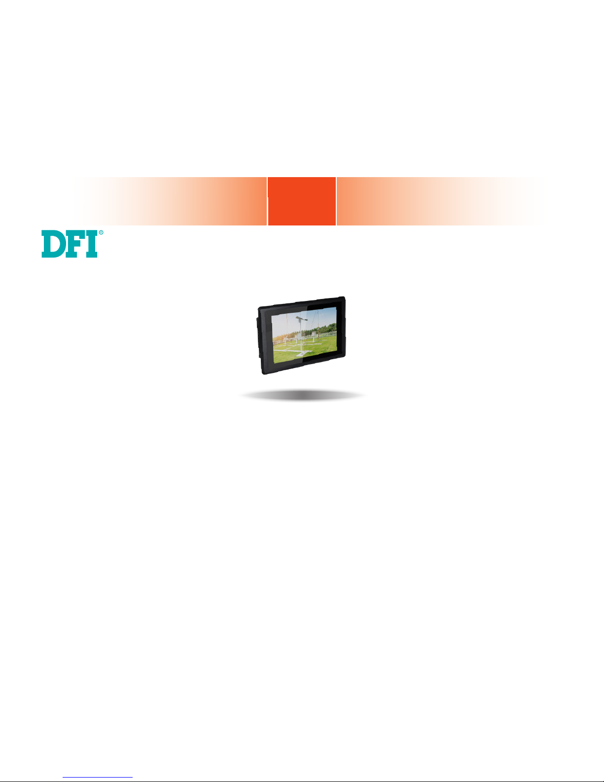
KS070-BT
7” Touch Panel PC
User’s Manual
A47200736
Page 2

www.d.com
2
Chapter 1 Introduction
Copyright
This publication contains information that is protected by copyright. No part of it may be reproduced in any form or by any means or used to make any transformation/adaptation without
the prior written permission from the copyright holders.
This publication is provided for informational purposes only. The manufacturer makes no
representations or warranties with respect to the contents or use of this manual and specifically disclaims any express or implied warranties of merchantability or fitness for any particular
purpose. The user will assume the entire risk of the use or the results of the use of this document. Further, the manufacturer reserves the right to revise this publication and make changes
to its contents at any time, without obligation to notify any person or entity of such revisions
or changes.
Changes after the publication’s first release will be based on the product’s revision. The website
will always provide the most updated information.
© 2017. All Rights Reserved.
Trademarks
Product names or trademarks appearing in this manual are for identification purpose only and
are the properties of the respective owners.
FCC and DOC Statement on Class A
This equipment has been tested and found to comply with the limits for a Class A digital
device, pursuant to Part 15 of the FCC rules. These limits are designed to provide reasonable protection against harmful interference when the equipment is operated in a residential
installation. This equipment generates, uses and can radiate radio frequency energy and, if not
installed and used in accordance with the instruction manual, may cause harmful interference
to radio communications. However, there is no guarantee that interference will not occur in a
particular installation. If this equipment does cause harmful interference to radio or television
reception, which can be determined by turning the equipment off and on, the user is encouraged to try to correct the interference by one or more of the following measures:
• Reorient or relocate the receiving antenna.
• Increase the separation between the equipment and the receiver.
• Connect the equipment into an outlet on a circuit different from that to which the receiver
is connected.
• Consult the dealer or an experienced radio TV technician for help.
Notice:
1. The changes or modifications not expressly approved by the party responsible for compli-
ance could void the user’s authority to operate the equipment.
2. Shielded interface cables must be used in order to comply with the emission limits.
Page 3

www.d.com
3
Chapter 1 Introduction
Table of Contents
Copyright ............................................................................2
Trademarks .........................................................................2
FCC and DOC Statement on Class A ....................................2
About this Manual ...............................................................4
Warranty ...........................................................................4
Static Electricity Precautions ................................................4
Safety Measures..................................................................4
Safety Precautions ..............................................................5
About the Package ..............................................................5
Chapter 1 - Introduction ......................................................6
Overview .................................................................................6
Key Features ...........................................................................6
Specifications ...........................................................................7
Getting to Know the KS070-BT ................................................8
Mechanical Dimensions ............................................................9
Chapter 2 - Getting Started ...............................................10
Chapter 3 - Installing Devices ............................................11
Removing the Chassis Cover ...................................................11
Installing a SATA Drive ...........................................................12
Chapter 4 - Jumper Settings ..............................................14
Clear CMOS Data ................................................................... 14
Auto Power-on Select .............................................................14
USB Power Select ..................................................................15
Panel Power Select ................................................................15
Backlight Enable Power Select ................................................16
Dimming Mode Select ............................................................16
Digital I/O Power Select .........................................................17
Digital I/O Output State ......................................................... 17
LCD/Inverter Power Select......................................................18
COM 4/DIO Select .................................................................18
Chapter 5 - Ports and Connectors ......................................19
Top Panel I/O Ports ...............................................................19
Bottom Panel I/O Ports ..........................................................19
USB Ports ...................................................................................................20
COM (Serial) Ports ......................................................................................21
Graphics Interfaces .....................................................................................22
DC-in Power Connector ..............................................................................23
RJ45 LAN Ports ...........................................................................................23
Audio Output .............................................................................................. 24
I/O Connectors ...................................................................... 24
Serial ATA Connector ..................................................................................24
Serial ATA Power Connector ........................................................................ 24
LVDS LCD Panel ........................................................................................25
Cooling Fan Connector ................................................................................26
Chassis Intrusion Connector ....................................................................... 26
Expansion Slots .......................................................................................... 27
Battery ....................................................................................................... 27
Chapter 6 - Mounting Options ...........................................28
Wall Mount ............................................................................28
Panel Mount ..........................................................................29
Chapter 7 - BIOS Setup ....................................................31
Chapter 8 - Supported Software ........................................44
Appendix A - System Error Message ..................................55
Appendix B - Troubleshooting Checklist ..............................57
Page 4

www.d.com
4
Chapter 1 Introduction
About this Manual
An electronic file of this manual is included in the CD. To view the user’s manual in the CD, insert the CD into a CD-ROM drive. The autorun screen (Main Board Utility CD) will appear. Click
“User’s Manual” on the main menu.
Warranty
1. Warranty does not cover damages or failures that arised from misuse of the product,
inability to use the product, unauthorized replacement or alteration of components and
product specifications.
2. The warranty is void if the product has been subjected to physical abuse, improper installation, modification, accidents or unauthorized repair of the product.
3. Unless otherwise instructed in this user’s manual, the user may not, under any circumstances, attempt to perform service, adjustments or repairs on the product, whether in or
out of warranty. It must be returned to the purchase point, factory or authorized service
agency for all such work.
4. We will not be liable for any indirect, special, incidental or consequential damages to the
product that has been modified or altered.
Static Electricity Precautions
It is quite easy to inadvertently damage your PC, system board, components or devices even
before installing them in your system unit. Static electrical discharge can damage computer
components without causing any signs of physical damage. You must take extra care in handling them to ensure against electrostatic build-up.
1. To prevent electrostatic build-up, leave the system board in its anti-static bag until you are
ready to install it.
2. Wear an antistatic wrist strap.
3. Do all preparation work on a static-free surface.
4. Hold the device only by its edges. Be careful not to touch any of the components, contacts
or connections.
5. Avoid touching the pins or contacts on all modules and connectors. Hold modules or connectors by their ends.
Safety Measures
To avoid damages to the system:
• Use the correct AC input voltage range.
To reduce the risk of electric shock:
• Unplug the power cord before removing the system chassis cover for installation or servic-
ing. After installation or servicing, cover the system chassis before plugging the power cord.
Battery:
• Danger of explosion if battery incorrectly replaced.
• Replace only with the same or equivalent type recommend by the manufacturer.
• Dispose of used batteries according to local ordinance.
Important:
Electrostatic discharge (ESD) can damage your processor, disk drive and other components. Perform the upgrade instruction procedures described at an ESD workstation only. If such a station is not available, you can provide some ESD protection by
wearing an antistatic wrist strap and attaching it to a metal part of the system chassis. If a wrist strap is unavailable, establish and maintain contact with the system
chassis throughout any procedures requiring ESD protection.
Page 5

www.d.com
5
Chapter 1 Introduction
About the Package
The package contains the following items. If any of these items are missing or damaged,
please contact your dealer or sales representative for assistance.
• One 7” Touch Panel PC
• One
sheet of Poron Foam
• One HDD drive bay kit
• One CD disk includes: Manual
Optional Items
• Wall Mount kit
• Panel Mount kit
• Power Cord
The board and accessories in the package may not come similar to the information listed
above. This may differ in accordance to the sales region or models in which it was sold. For
more information about the standard package in your region, please contact your dealer or
sales representative.
Safety Precautions
• Use the correct DC input voltage range.
• Unplug the power cord before removing the system chassis cover for installation or servicing. After installation or servicing, cover the system chassis before plugging the power cord.
• Danger of explosion if battery incorrectly replaced.
• Replace only with the same or equivalent type recommend by the manufacturer.
• Dispose of used batteries according to local ordinance.
• Keep this system away from humidity.
• Place the system on a stable surface. Dropping it or letting it fall may cause damage.
• The openings on the system are for air ventilation to protect the system from overheating.
DO NOT COVER THE OPENINGS.
• Place the power cord in such a way that it will not be stepped on. Do not place anything on
top of the power cord. Use a power cord that has been approved for use with the system
and that it matches the voltage and current marked on the system’s electrical range label.
• If the system will not be used for a long time, disconnect it from the power source to avoid
damage by transient overvoltage.
• If one of the following occurs, consult a service personnel:
- The power cord or plug is damaged.
- Liquid has penetrated the system.
- The system has been exposed to moisture.
- The system is not working properly.
- The system dropped or is damaged.
- The system has obvious signs of breakage.
• The unit uses a three-wire ground cable which is equipped with a third pin to ground the
unit and prevent electric shock. Do not defeat the purpose of this pin. If your outlet does
not support this kind of plug, contact your electrician to replace the outlet.
• Disconnect the system from the DC outlet before cleaning. Use a damp cloth. Do not use
liquid or spray detergents for cleaning.
Page 6
www.d.com
6
Chapter 1 Introduction
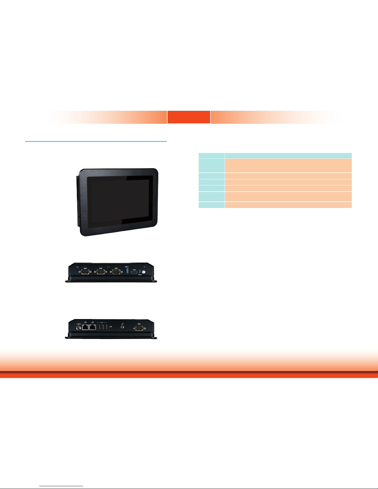
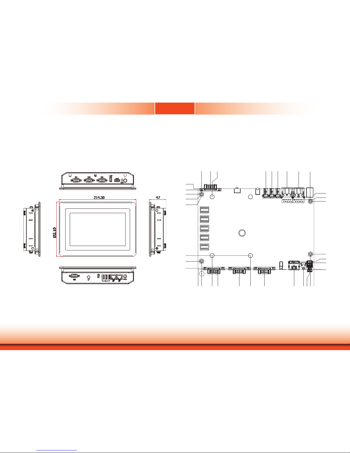
Chapter 1 - Introduction
Chapter 1
Overview
KS070-BT
Top View
Key Features
Model Name KS070-BT
Processor Intel
®
Atom™ Processor E3800 Series, BGA 1170
Intel® Atom™ Processor E3845, Quad Core, 2M Cache, 1.91GHz, 10W
Intel® Celeron® Processor J1900, Quad Core, 2M Cache, 2GHz (2.42GHz), 10W
LAN 2 LAN ports
COM 4 COM ports (one of them can be an 8-bit DIO)
Display 1 HDMI port
USB 3 USB 2.0 ports
1 USB 3.0 port
Audio Line-out and Microphone port
Side View
Bottom View
Page 7
www.d.com
7
Chapter 1 Introduction
Specifications
Chapter 1
Note:
*Optional items are not supported in standard model. Please contact your sales representative for more information.
Processor Intel® Atom™ Processor E3800 Series, BGA 1170
Intel® Atom™ Processor E3845, Quad Core, 2M Cache, 1.91GHz, 10W
Intel® Celeron® Processor J1900, Quad Core, 2M Cache, 2GHz (2.42GHz), 10W
Memory 4GB/2GB Memory Down
Single Channel DDR3L 1333MHz
BIOS AMI SPI 64Mbit
Display and Touch
Screen
• Display: 7” 800x480 TFT LCD Panel with Capacitive Touch Screen
• Brightness: 500 cd/m²
• Contrast: 400:1
• Backlight Lifetime: 50,000 hours
Graphics Intel
®
HD Graphics
Display port: HDMI (resolution up to 1920x1080 @ 60Hz)
Supported applications: DirectX 11, OCL 1.2, OGL 4.0
Supported Codecs:
H.264, MPEG2, MVC, VC-1, WMV9, VP8 (the supported version is
dependent on the OS)
Storage 1 x 2.5" SATA 2.0 Drive Bay
1 x micro SD (available upon request)
Expansion 1 x Full-size Mini PCIe (PCIe/USB/4G)
1 x Full-size Mini PCIe (mSATA)
1 x Half-size Mini PCIe (PCIe/USB/LPC)
1 x SIM Socket
Audio Controller Realtek ALC888 5.1-channel
Ethernet Controller 2 x Intel
®
I210AT PCIe (10/100/1000Mbps)
LED Indicators 1 x Power LED
1 x Status LED
Top I/O Ports 3 x RS-232/422/485 (DB-9, one of them supports 8-bit DIO)
1 x USB 3.0 (type A)
1 x HDMI
1 x Power Button
1 x Reset Button
2 x Wi-Fi Module Antenna Hole
Bottom I/O Ports 2 x GbE (RJ-45) (10/100/1000Mbps)
1 x RS-232 (DB-9)
3 x USB 2.0 (type A)
1 x Line-out
1 x Mic-in
1 x DC-in connector
Watchdog Timer System Reset, Programmable via Software from 1 to 255 Seconds
Power Type:12~36V DC
Connector: DC Jack
OS Support Windows 7 (32bit/64bit)
Windows 10 IoT Enterprise (32bit/64bit)
Windows 8.1 Embedded (32bit/64bit) (available upon request)
Mechanism Construction: Sheet Metal
IP Rating: IP65 Front Panel Protection
Mounting: Panel/VESA Mount (*)
Weight: 2kg
Dimensions (W x H x D): 214.3mm x 152.1mm x 47mm
Environment Operating Temperature: 0 to 60°C
Storage Temperature: -30 to 80°C
Relative Humidity: 5 to 85% RH (non-condensing)
Tests and
Certication
Shock:
OP: Half-sine, 3G @ 11ms
Non-OP: Half-sine, 5G @ 11ms
Vibration:
OP: Random, 1Grms @ 5~500Hz, 30min
Non-OP: Sweep sine, 3Grms @ 10~500Hz, 30min
Page 8
www.d.com
8
Chapter 1 Introduction
Power Button with LED (Green)
Press to power on or power off the system.
Status LED (Blue)
Indicates system status.
Reset Button
Press to restart the system without going through a full shutdown and boot cycle.
HDMI Port
Connects to the HDMI port of a display.
USB 3.0 Port
Connects USB 3.0 devices as well as devices from previous versions such as USB
2.0 or USB 1.1.
COM Ports
COM 1, COM 2 and COM 4 can be an RS232, RS422 or RS485 port. COM 4 can be
used as an 8-bit Digital I/O or a serial port via jumper selection.
Wireless Antenna Holes
Reserved for installing wireless antennas.
Getting to Know the KS070-BT
Chapter 1
Top View
Bottom View
DC-in
Plug a power adapter into this socket.
LAN Ports
Connect a network device or a LAN cable for network connectivity.
USB 2.0 Ports
Connect USB 2.0 or 1.1 devices.
Line-out
Connects a speaker.
Mic-in
Connects a microphone.
COM Port
Connects serial devices. COM 3 can be an RS232, RS422 or RS485 port.
Status LED
Suspend Mode S0 S1-S3 (sleep) S4, S5
LED Behavior
Off Blink Off
HDMI
USB 3.0
Reset/
Status LED
Power
Antenna
hole
Antenna
hole
COM 4, COM 2, COM 1
Line-out
COM 3
USB 2.0
LAN 1 LAN 2
DC-in
Mic-in
Page 9
www.d.com
9
Chapter 1 Introduction
Motherboard Dimensions
Chapter 1
Mechanical Dimensions
KS070-BT
Bottom View
Top View
Right View
Left View
Front View
0
0
6.1
14.9
28.4
70.4
106.41
142.4
160
165
5
160
147.4
21.81
38.31
51.4
59.9
68.4
90.4
144.9
5
144.9
21.8
9.65
97
107
115
11.8
19.8
103.35
99.26
102.93
113.4
11.45
1.6
105.85
DC-in
Page 10

www.d.com
10
Chapter 2 Getting Started
Chapter 2 - Getting Started
Chapter 2
Preparing the System
Before you start using the system, you need the following items:
• SATA hard drive
• AC power adapter
• CD-ROM drive (for installing software/drivers)
Installing Devices
The following are devices that can be installed in the system.
• SATA hard drive
• Mini PCIe/mSATA card
Configuring the BIOS
To get you started, you may need to change configurations such as the date, time and the
type of hard disk drive.
1. Power on the system.
2. After the memory test, the message “Press DEL to run setup” will appear on the screen.
Press the Delete key to enter the BIOS setup utility.
Installing the Operating System
Depending on the method you choose to install your system, you may use a USB flash drive
or install a CD-ROM drive in order to run the Operating System CD.
Make sure that a 2.5” SATA drive is already installed.
1. Refer to the following chapters for information on installing a SATA drive.
2. Refer to your operating system manual for instructions on installing the operating system.
Installing the Drivers
The system package includes a CD disk. The CD includes drivers that must be installed to provide the best system performance. Refer to the Supported Software chapter for instructions on
installing the drivers.
Page 11
www.d.com
11
Chapter 3 Installing Devices
Chapter 3
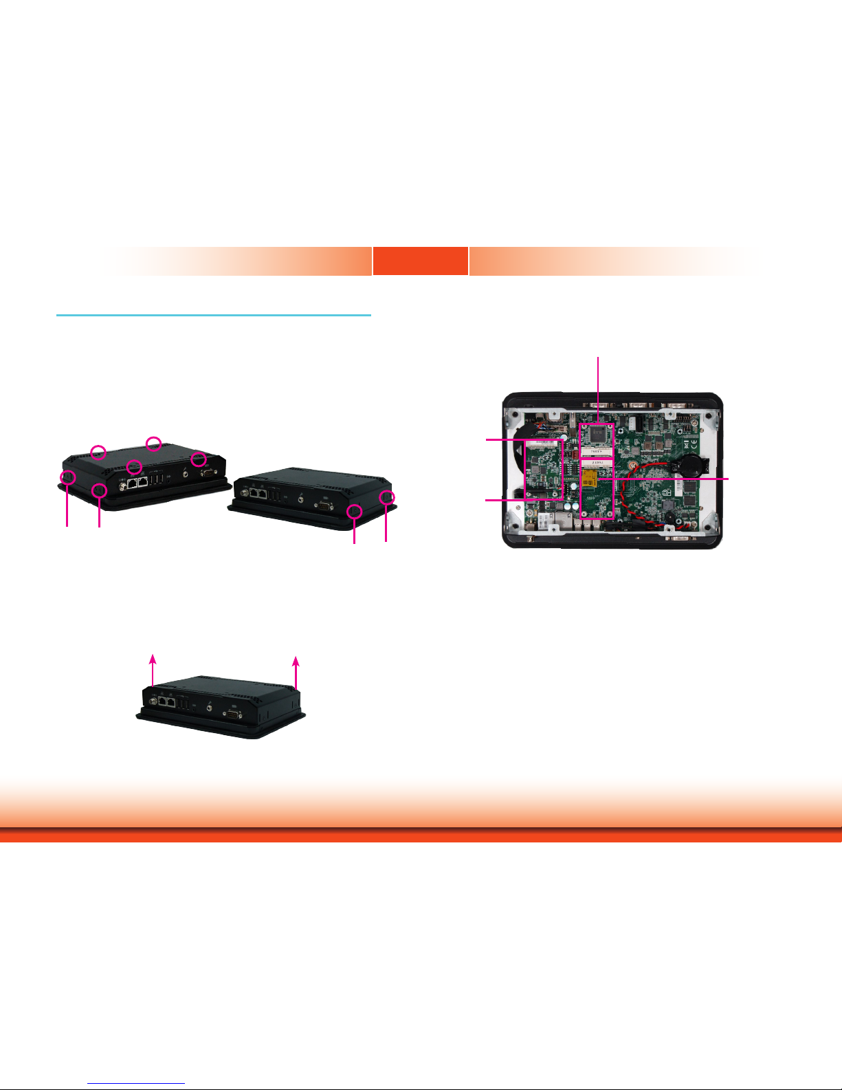
Chapter 3 - Installing Devices
Removing the Chassis Cover
5. The Mini PCIe and the microSD slots are readily accessible after removing the chassis cover.
Lift the cover upward
1. Make sure the system and all other peripheral devices connected to it have been powered off.
2. Disconnect all power cords and cables.
3. The 8 mounting screws on the rear side of the system are used to secure the cover to the
chassis. Remove these screws and put them in a safe place for later use.
4. Lift the cover up to open the system.
microSD socket
Mini PCIe slot
Mini PCIe slot
Mounting screw
Mounting screw
Page 12
www.d.com
12
Chapter 3 Installing Devices
Chapter 3
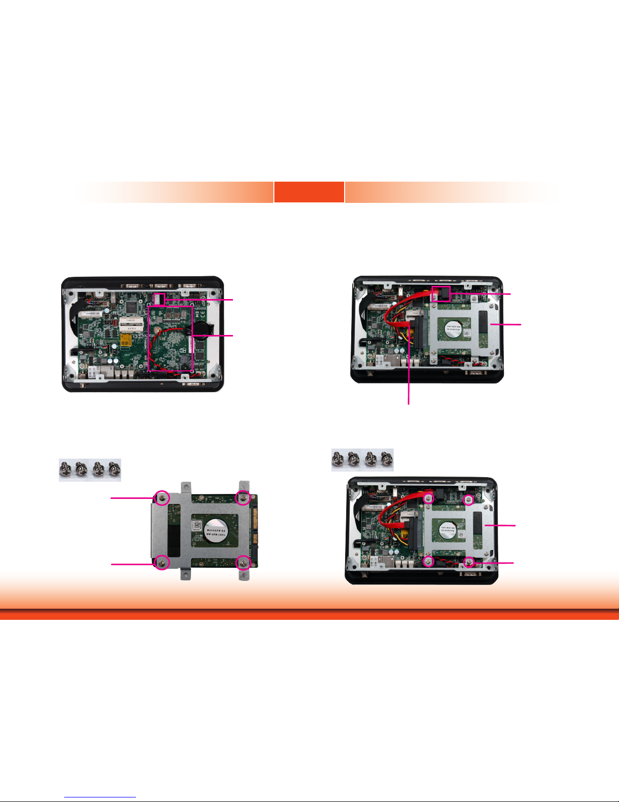
Installing a SATA Drive
1. The SATA data and power connectors are on the system board.
2. Align the mounting holes of the SATA HDD with the mounting holes on the HDD drive bay
and use the provided mounting screws to attach the SATA HDD to the drive bay.
3. Connect one end of the SATA cable to the SATA power and data connectors on the SATA
drive and the other end of the SATA cable to the SATA power and data connectors on the
system board.
4. Align the mounting holes of the HDD drive bay with the mounting holes on the system and
use the provided mounting screws to secure the drive bay in place.
SATA mounting location
SATA connectors
Mounting screw
Mounting screw
SATA drive
SATA connectors
SATA power/data cable
SATA drive
Mounting screw
Page 13

www.d.com
13
Chapter 3 Installing Devices
Chapter 3
Installing a Mini PCIe Card
Note:
The system also has one additional full-size Mini PCIe and one half-size Mini PCIe slot
that use the mSATA and LPC interface respectively.
Note:
The system also has one additional full-size Mini PCIe and one half-size Mini PCIe slot
that use the PCIe and LPC interface respectively.
The system board is equipped with 3 Mini PCIe slots: two full-size and one half-size slots.
Here we will demonstrate the installation of a full-size Mini PCIe card (mSATA interface) for
capacity expansion.
1. Grasp the Mini PCIe card by its edges and align the notch in the connector of the PCIe
card with the notch in the connector on the system board.
2. Push the Mini PCIe card down and use the provided mounting screws to secure the card on
the system board.
Mounting screw
Page 14
www.d.com
14
Chapter 4
Chapter 4 Jumper Settings
LAN 2
LAN 1
3
DDR3L
DDR3L
DDR3L
DDR3L
Mini PCIe with SIM
COM 4
RS232/RS422/RS485
1210
31
JP22
1
1
1
(JP20)
(JP18)
(JP17)
(JP21)
1 3
1210
COM 2
RS232/RS422/RS485
COM 1
RS232/RS422/RS485
USB 0
USB 3.0
HDMI
Reset
Power
3940
2
1
LVDS LCD
Panel
USB 7
USB 6
Mic-in
1
Battery
Buzzer
1
Chassis
Intrusion
1
Clear CMOS
Data (JP24)
SPI
Flash
BIOS
eMMC
(optional)
iTE
IT8528E
Mini PCIe with LPC mSATA
MicroSD
(optional)
1
System Fan
1
USB 0
Power
Select
(JP5)
125
6
(JP23)
1
1
1
(JP3)
(JP4)
1
2 10
9
COM 6
1109
COM 5
1 1
USB 2 Power
Select (JP6)
USB 5-7 Power
Select (JP7)
1
2 10
9
USB 5
(JP25)
USB 2.0
USB 2.0
(JP17)
(JP20)
COM 4/DIO Select
(JP22, JP21)
Digital I/O 0-3 Output State
Digital I/O Power Select
Panel Power Select
(JP3)
(JP4)
(JP23)
Backlight Enable Power Select
Auto Power-on Select
(JP25)
Dimming Mode Select
(JP18)
Digital I/O 4-7 Output State
1
COM 3
RS232/RS422/RS485
4
1
(JP2)
(JP2)LCD/Inverter Power Select
SATA 1
4 1
SATA
Power
1
SATA 2.0
Line-out
DC-in
USB 2
USB 2
USB 2
USB 2
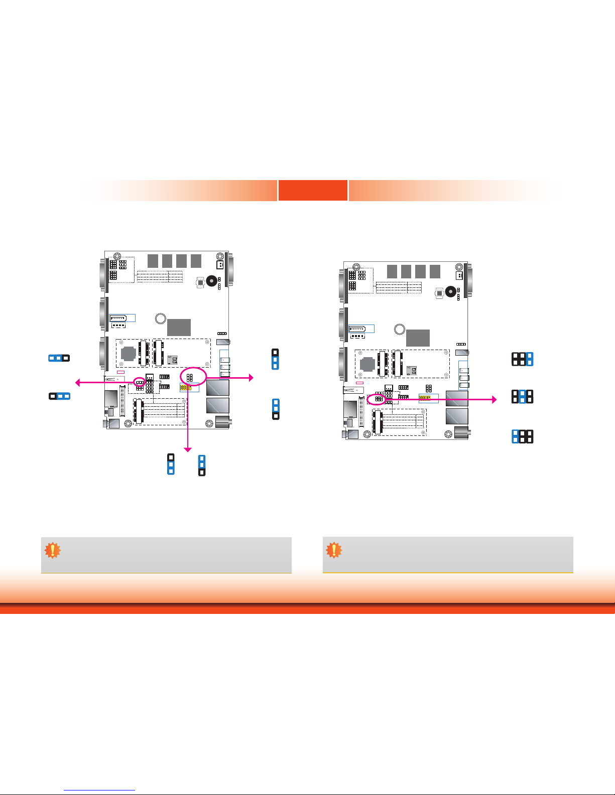
Clear CMOS Data
JP24
You can reconfigure the system with the default values stored in the ROM BIOS if you encounter the following situations:
a) CMOS data becomes corrupted.
b) You forgot the supervisor or user password.
To load the default values stored in the ROM BIOS, please follow these steps below:
1. Power off the system and unplug the power cord.
2. Set jumper pins 2 and 3 to On. Wait for a few seconds and set the jumper back to its de-
fault setting, pins 1 and 2 On.
3. Now plug the power cord and power on the system.
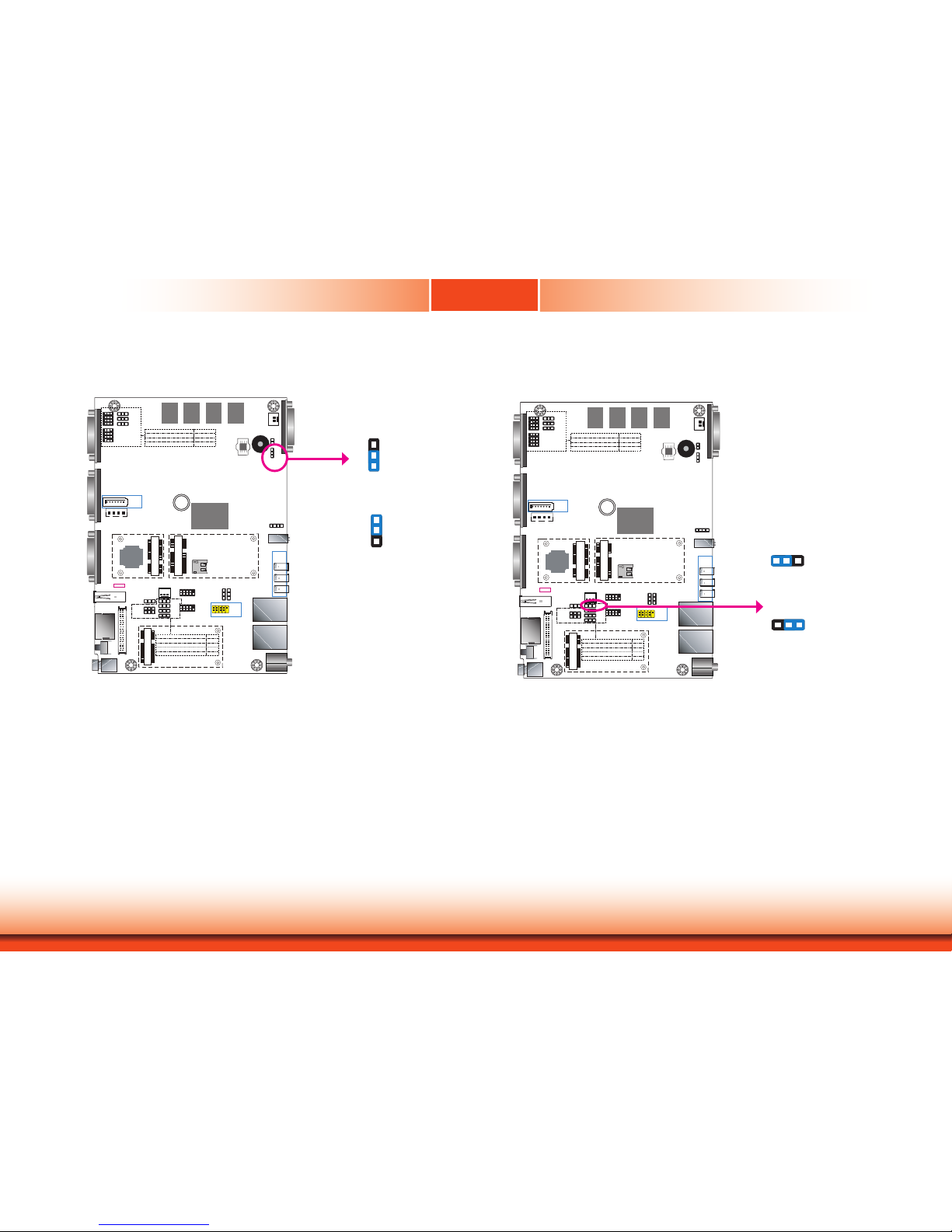
1-2 On:
Normal (default)
1
3
2
2-3 On:
Clear CMOS Data
1
3
2
Auto Power-on Select
1-2 On:
Power-on via power button
(default)
2-3 On:
Power-on via AC power
JP25 is used to select the method of powering on the system. If you want the system to
power on whenever AC power comes in, set JP25 pins 2 and 3 to On. If you want to use the
power button, set pins 1 and 2 to On.
When using the JP25 “Power On” feature to power the system back on after a power failure, the system may not power on if the power lost is resumed within 5 seconds (i.e., power
flicker).
JP25
LAN 2
LAN 1
3
DDR3L
DDR3L
DDR3L
DDR3L
Mini PCIe with SIM
COM 4
RS232/RS422/RS485
1210
31
JP22
1
1
1
(JP20)
(JP18)
(JP17)
(JP21)
1 3
1210
COM 2
RS232/RS422/RS485
COM 1
RS232/RS422/RS485
USB 0
USB 3.0
HDMI
Reset
Power
3940
2
1
LVDS LCD
Panel
USB 7
USB 6
Mic-in
1
Battery
Buzzer
1
Chassis
Intrusion
1
Clear CMOS
Data (JP24)
SPI
Flash
BIOS
eMMC
(optional)
iTE
IT8528E
Mini PCIe with LPC mSATA
MicroSD
(optional)
1
System Fan
1
USB 0
Power
Select
(JP5)
125
6
(JP23)
1
1
1
(JP3)
(JP4)
1
2 10
9
COM 6
1109
COM 5
1 1
USB 2 Power
Select (JP6)
USB 5-7 Power
Select (JP7)
1
2 10
9
USB 5
(JP25)
USB 2.0
USB 2.0
(JP17)
(JP20)
COM 4/DIO Select
(JP22, JP21)
Digital I/O 0-3 Output State
Digital I/O Power Select
Panel Power Select
(JP3)
(JP4)
(JP23)
Backlight Enable Power Select
Auto Power-on Select
(JP25)
Dimming Mode Select
(JP18)
Digital I/O 4-7 Output State
1
COM 3
RS232/RS422/RS485
4
1
(JP2)
(JP2)LCD/Inverter Power Select
SATA 1
4 1
SATA
Power
1
SATA 2.0
Line-out
DC-in
USB 2
USB 2
USB 2
USB 2
1 32
1 32
Chapter 4 - Jumper Settings
Page 15
www.d.com
15
Chapter 4
Chapter 4 Jumper Settings
LAN 2
LAN 1
3
DDR3L
DDR3L
DDR3L
DDR3L
Mini PCIe with SIM
COM 4
RS232/RS422/RS485
1210
31
JP22
1
1
1
(JP20)
(JP18)
(JP17)
(JP21)
1 3
1210
COM 2
RS232/RS422/RS485
COM 1
RS232/RS422/RS485
USB 0
USB 3.0
HDMI
Reset
Power
3940
2
1
LVDS LCD
Panel
USB 7
USB 6
Mic-in
1
Battery
Buzzer
1
Chassis
Intrusion
1
Clear CMOS
Data (JP24)
SPI
Flash
BIOS
eMMC
(optional)
iTE
IT8528E
Mini PCIe with LPC mSATA
MicroSD
(optional)
1
System Fan
1
USB 0
Power
Select
(JP5)
125
6
(JP23)
1
1
1
(JP3)
(JP4)
1
2 10
9
COM 6
1109
COM 5
1 1
USB 2 Power
Select (JP6)
USB 5-7 Power
Select (JP7)
1
2 10
9
USB 5
(JP25)
USB 2.0
USB 2.0
(JP17)
(JP20)
COM 4/DIO Select
(JP22, JP21)
Digital I/O 0-3 Output State
Digital I/O Power Select
Panel Power Select
(JP3)
(JP4)
(JP23)
Backlight Enable Power Select
Auto Power-on Select
(JP25)
Dimming Mode Select
(JP18)
Digital I/O 4-7 Output State
1
COM 3
RS232/RS422/RS485
4
1
(JP2)
(JP2)LCD/Inverter Power Select
SATA 1
4 1
SATA
Power
1
SATA 2.0
Line-out
DC-in
USB 2
USB 2
USB 2
USB 2
JP5, JP6 and JP7 are used to select the power for the USB ports of USB 0, USB 2 and USB 5-7
respectively. Selecting +5V_standby will allow you to use USB devices to wake up the system.
USB Power Select
1 32
1 32
1-2 On:
+5V_standby
(default)
2-3 On: +5V
Important:
If you are using the Wake-On-USB Keyboard/Mouse function for 2 USB ports, the
+5V_standby power source of your power supply must support ≥1.5A. For 3 or more
USB ports, the +5V_standby power source of your power supply must support ≥2A.
USB 0
(JP5)
USB 5-7
(JP7)
1
3
2
1
3
2
USB 2
(JP6)
Panel Power Select
LAN 2
LAN 1
3
DDR3L
DDR3L
DDR3L
DDR3L
Mini PCIe with SIM
COM 4
RS232/RS422/RS485
1210
31
JP22
1
1
1
(JP20)
(JP18)
(JP17)
(JP21)
1 3
1210
COM 2
RS232/RS422/RS485
COM 1
RS232/RS422/RS485
USB 0
USB 3.0
HDMI
Reset
Power
3940
2
1
LVDS LCD
Panel
USB 7
USB 6
Mic-in
1
Battery
Buzzer
1
Chassis
Intrusion
1
Clear CMOS
Data (JP24)
SPI
Flash
BIOS
eMMC
(optional)
iTE
IT8528E
Mini PCIe with LPC mSATA
MicroSD
(optional)
1
System Fan
1
USB 0
Power
Select
(JP5)
125
6
(JP23)
1
1
1
(JP3)
(JP4)
1
2 10
9
COM 6
1109
COM 5
1 1
USB 2 Power
Select (JP6)
USB 5-7 Power
Select (JP7)
1
2 10
9
USB 5
(JP25)
USB 2.0
USB 2.0
(JP17)
(JP20)
COM 4/DIO Select
(JP22, JP21)
Digital I/O 0-3 Output State
Digital I/O Power Select
Panel Power Select
(JP3)
(JP4)
(JP23)
Backlight Enable Power Select
Auto Power-on Select
(JP25)
Dimming Mode Select
(JP18)
Digital I/O 4-7 Output State
1
COM 3
RS232/RS422/RS485
4
1
(JP2)
(JP2)LCD/Inverter Power Select
SATA 1
4 1
SATA
Power
1
SATA 2.0
Line-out
DC-in
USB 2
USB 2
USB 2
USB 2
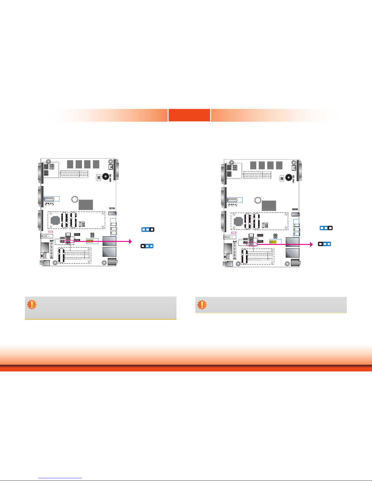
JP23 is used to select the power supplied with the LCD panel.
Important:
Before powering on the system, make sure that the power settings of JP23 match
the LCD panel’s specification. Selecting the incorrect voltage will seriously damage the
LCD panel.
1-2 On: +12V
3-4 On:+5V
5-6 On: +3.3V
(default)
JP23
6 4 2
5 3 1
1
3
2
1
3
2
1-2 On:
+5V_standby
(default)
2-3 On: +5V
1-2 On:
+5V_standby
(default)
2-3 On: +5V
6 4 2
5 3 1
6 4 2
5 3 1
Page 16
www.d.com
16
Chapter 4
Chapter 4 Jumper Settings
Backlight Enable Power Select
LAN 2
LAN 1
3
DDR3L
DDR3L
DDR3L
DDR3L
Mini PCIe with SIM
COM 4
RS232/RS422/RS485
1210
31
JP22
1
1
1
(JP20)
(JP18)
(JP17)
(JP21)
1 3
1210
COM 2
RS232/RS422/RS485
COM 1
RS232/RS422/RS485
USB 0
USB 3.0
HDMI
Reset
Power
3940
2
1
LVDS LCD
Panel
USB 7
USB 6
Mic-in
1
Battery
Buzzer
1
Chassis
Intrusion
1
Clear CMOS
Data (JP24)
SPI
Flash
BIOS
eMMC
(optional)
iTE
IT8528E
Mini PCIe with LPC mSATA
MicroSD
(optional)
1
System Fan
1
USB 0
Power
Select
(JP5)
125
6
(JP23)
1
1
1
(JP3)
(JP4)
1
2 10
9
COM 6
1109
COM 5
1 1
USB 2 Power
Select (JP6)
USB 5-7 Power
Select (JP7)
1
2 10
9
USB 5
(JP25)
USB 2.0
USB 2.0
(JP17)
(JP20)
COM 4/DIO Select
(JP22, JP21)
Digital I/O 0-3 Output State
Digital I/O Power Select
Panel Power Select
(JP3)
(JP4)
(JP23)
Backlight Enable Power Select
Auto Power-on Select
(JP25)
Dimming Mode Select
(JP18)
Digital I/O 4-7 Output State
1
COM 3
RS232/RS422/RS485
4
1
(JP2)
(JP2)LCD/Inverter Power Select
SATA 1
4 1
SATA
Power
1
SATA 2.0
Line-out
DC-in
USB 2
USB 2
USB 2
USB 2
JP3 is used to select the power level of backlight brightness control: +5V or +3.3V.
Important:
Before powering-on the system, make sure that the power settings of JP3 match the
power specification of backlight control. Selecting the incorrect voltage will seriously
damage the backlight.
JP3
1 32
1-2 On: +3.3V (default)
1 32
2-3 On: +5V
Dimming Mode Select
LAN 2
LAN 1
3
DDR3L
DDR3L
DDR3L
DDR3L
Mini PCIe with SIM
COM 4
RS232/RS422/RS485
1210
31
JP22
1
1
1
(JP20)
(JP18)
(JP17)
(JP21)
1 3
1210
COM 2
RS232/RS422/RS485
COM 1
RS232/RS422/RS485
USB 0
USB 3.0
HDMI
Reset
Power
3940
2
1
LVDS LCD
Panel
USB 7
USB 6
Mic-in
1
Battery
Buzzer
1
Chassis
Intrusion
1
Clear CMOS
Data (JP24)
SPI
Flash
BIOS
eMMC
(optional)
iTE
IT8528E
Mini PCIe with LPC mSATA
MicroSD
(optional)
1
System Fan
1
USB 0
Power
Select
(JP5)
125
6
(JP23)
1
1
1
(JP3)
(JP4)
1
2 10
9
COM 6
1109
COM 5
1 1
USB 2 Power
Select (JP6)
USB 5-7 Power
Select (JP7)
1
2 10
9
USB 5
(JP25)
USB 2.0
USB 2.0
(JP17)
(JP20)
COM 4/DIO Select
(JP22, JP21)
Digital I/O 0-3 Output State
Digital I/O Power Select
Panel Power Select
(JP3)
(JP4)
(JP23)
Backlight Enable Power Select
Auto Power-on Select
(JP25)
Dimming Mode Select
(JP18)
Digital I/O 4-7 Output State
1
COM 3
RS232/RS422/RS485
4
1
(JP2)
(JP2)LCD/Inverter Power Select
SATA 1
4 1
SATA
Power
1
SATA 2.0
Line-out
DC-in
USB 2
USB 2
USB 2
USB 2
JP4
2-3 On: PWM Mode
(default)
1 32
1-2 On: Voltage Mode
1 32
JP4 allows you to select the mode for the backlight brightness control of the LVDS panel.
Important:
You need to refer to your panel’s user guide to determine the type of mode (PWM or
Voltage) that is appropriate for your panel.
Page 17
www.d.com
17
Chapter 4
Chapter 4 Jumper Settings
Digital I/O Power Select
JP17 is used to select the power of the DIO (Digital Input/Output) signal.
Digital I/O Output State
Based on the power level of DIO (Digital I/O) selected on JP17, JP20 (for DIO pin 0-3) and
JP18 (for DIO pin 4-7) are used to select the state of DIO output: pull-high or pull-low. When
selecting pull-high, the power selection will be set according to JP17’s setting.
LAN 2
LAN 1
3
DDR3L
DDR3L
DDR3L
DDR3L
Mini PCIe with SIM
COM 4
RS232/RS422/RS485
1210
31
JP22
1
1
1
(JP20)
(JP18)
(JP17)
(JP21)
1 3
1210
COM 2
RS232/RS422/RS485
COM 1
RS232/RS422/RS485
USB 0
USB 3.0
HDMI
Reset
Power
3940
2
1
LVDS LCD
Panel
USB 7
USB 6
Mic-in
1
Battery
Buzzer
1
Chassis
Intrusion
1
Clear CMOS
Data (JP24)
SPI
Flash
BIOS
eMMC
(optional)
iTE
IT8528E
Mini PCIe with LPC mSATA
MicroSD
(optional)
1
System Fan
1
USB 0
Power
Select
(JP5)
125
6
(JP23)
1
1
1
(JP3)
(JP4)
1
2 10
9
COM 6
1109
COM 5
1 1
USB 2 Power
Select (JP6)
USB 5-7 Power
Select (JP7)
1
2 10
9
USB 5
(JP25)
USB 2.0
USB 2.0
(JP17)
(JP20)
COM 4/DIO Select
(JP22, JP21)
Digital I/O 0-3 Output State
Digital I/O Power Select
Panel Power Select
(JP3)
(JP4)
(JP23)
Backlight Enable Power Select
Auto Power-on Select
(JP25)
Dimming Mode Select
(JP18)
Digital I/O 4-7 Output State
1
COM 3
RS232/RS422/RS485
4
1
(JP2)
(JP2)LCD/Inverter Power Select
SATA 1
4 1
SATA
Power
1
SATA 2.0
Line-out
DC-in
USB 2
USB 2
USB 2
USB 2
1 32
1 32
1-2 On:
+5V_standby
2-3 On: +5V
(default)
JP17
JP20 (DIO 0-3)
JP18 (DIO 4-7)
1 32
1 32
1-2 On:
GND (default)
2-3 On:
+5V or +5V_standby
Page 18
www.d.com
18
Chapter 4
Chapter 4 Jumper Settings
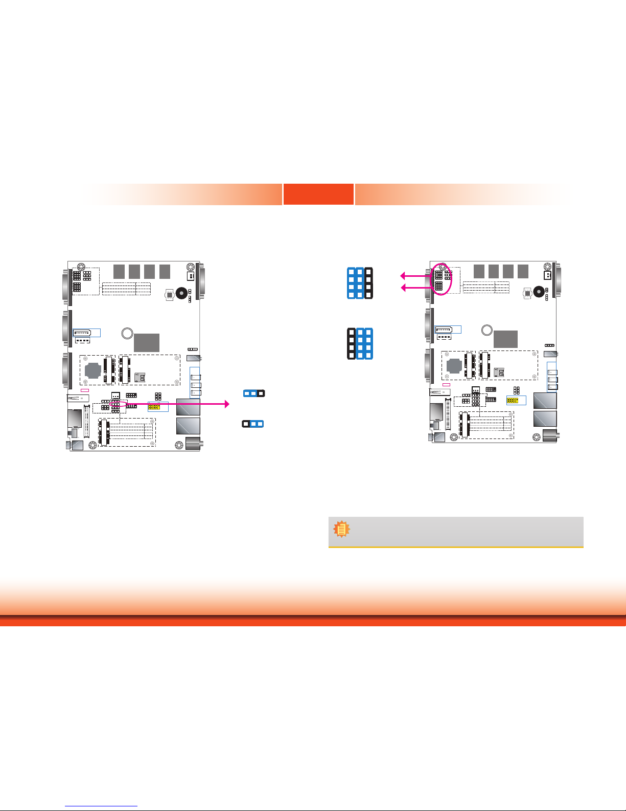
COM 4/DIO Select
1-2, 4-5, 7-8, 10-11 On:
COM 4 (default)
7 9
1 3
10 12
4 6
The system board uses JP21 and JP22 to select between RS232/422/485 COM 4 or an 8-bit
DIO connector.
Note:
You cannot use COM 4 and DIO at the same time. Please set up JP21 and
JP22 together.
LAN 2
LAN 1
3
DDR3L
DDR3L
DDR3L
DDR3L
Mini PCIe with SIM
COM 4
RS232/RS422/RS485
1210
31
JP22
1
1
1
(JP20)
(JP18)
(JP17)
(JP21)
1 3
1210
COM 2
RS232/RS422/RS485
COM 1
RS232/RS422/RS485
USB 0
USB 3.0
HDMI
Reset
Power
3940
2
1
LVDS LCD
Panel
USB 7
USB 6
Mic-in
1
Battery
Buzzer
1
Chassis
Intrusion
1
Clear CMOS
Data (JP24)
SPI
Flash
BIOS
eMMC
(optional)
iTE
IT8528E
Mini PCIe with LPC mSATA
MicroSD
(optional)
1
System Fan
1
USB 0
Power
Select
(JP5)
125
6
(JP23)
1
1
1
(JP3)
(JP4)
1
2 10
9
COM 6
1109
COM 5
1 1
USB 2 Power
Select (JP6)
USB 5-7 Power
Select (JP7)
1
2 10
9
USB 5
(JP25)
USB 2.0
USB 2.0
(JP17)
(JP20)
COM 4/DIO Select
(JP22, JP21)
Digital I/O 0-3 Output State
Digital I/O Power Select
Panel Power Select
(JP3)
(JP4)
(JP23)
Backlight Enable Power Select
Auto Power-on Select
(JP25)
Dimming Mode Select
(JP18)
Digital I/O 4-7 Output State
1
COM 3
RS232/RS422/RS485
4
1
(JP2)
(JP2)LCD/Inverter Power Select
SATA 1
4 1
SATA
Power
1
SATA 2.0
Line-out
DC-in
USB 2
USB 2
USB 2
USB 2
JP22
JP21
2-3, 5-6, 8-9, 11-12 On:
DIO
7 9
1 3
10 12
4 6
LCD/Inverter Power Select
LAN 2
LAN 1
3
DDR3L
DDR3L
DDR3L
DDR3L
Mini PCIe with SIM
COM 4
RS232/RS422/RS485
1210
31
JP22
1
1
1
(JP20)
(JP18)
(JP17)
(JP21)
1 3
1210
COM 2
RS232/RS422/RS485
COM 1
RS232/RS422/RS485
USB 0
USB 3.0
HDMI
Reset
Power
3940
2
1
LVDS LCD
Panel
USB 7
USB 6
Mic-in
1
Battery
Buzzer
1
Chassis
Intrusion
1
Clear CMOS
Data (JP24)
SPI
Flash
BIOS
eMMC
(optional)
iTE
IT8528E
Mini PCIe with LPC mSATA
MicroSD
(optional)
1
System Fan
1
USB 0
Power
Select
(JP5)
125
6
(JP23)
1
1
1
(JP3)
(JP4)
1
2 10
9
COM 6
1109
COM 5
1 1
USB 2 Power
Select (JP6)
USB 5-7 Power
Select (JP7)
1
2 10
9
USB 5
(JP25)
USB 2.0
USB 2.0
(JP17)
(JP20)
COM 4/DIO Select
(JP22, JP21)
Digital I/O 0-3 Output State
Digital I/O Power Select
Panel Power Select
(JP3)
(JP4)
(JP23)
Backlight Enable Power Select
Auto Power-on Select
(JP25)
Dimming Mode Select
(JP18)
Digital I/O 4-7 Output State
1
COM 3
RS232/RS422/RS485
4
1
(JP2)
(JP2)LCD/Inverter Power Select
SATA 1
4 1
SATA
Power
1
SATA 2.0
Line-out
DC-in
USB 2
USB 2
USB 2
USB 2
JP2
1 32
2-3 On: +5V
1 32
1-2 On: +12V (default)
JP2 is used to select the power level of the LCD/inverter power connector.
Page 19

19
Chapter 5
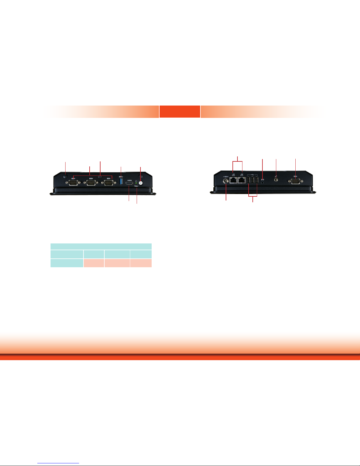
Chapter 5 Ports and Connectors
Top Panel I/O Ports
The top panel I/O consists of the following ports and connectors:
• 1 power button
• 1 reset button
• 1 HDMI port
• 1 USB 3.0 port
• 3 DB-9 serial ports
- Support RS232/RS422/RS485
- COM 4 supports an optional 8-bit DIO
The bottom panel I/O consists of the following ports and connectors:
• 1 DC-in power connector
• 2 RJ45 LAN ports
• 3 USB 2.0 ports
• 1 line-out and microphone jack
• 1 DB-9 serial port
- COM 3 supports RS232/RS422/RS485
Bottom Panel I/O Ports
Chapter 5 - Ports and Connectors
COM 4COM 2COM 1
USB 3.0
Reset Button
HDMI
DC-in
COM 3
Power button
LAN 2 LAN 1
USB 2.0
Line-out
Mic-in
Page 20

20
Chapter 5
Chapter 5 Ports and Connectors
USB Ports
The USB device allows data exchange between your computer and a wide range of simultaneously accessible external Plug and Play peripherals.
The system board is equipped with one external USB 3.0 port (USB 0) and three external USB
2.0 ports (USB 2/6/7). In addition, it also has a 10-pin connector and allows you to connect
one additional USB 2.0 port (USB 5).
BIOS Setting
Configure the onboard USB in the Advanced menu (“USB Configuration” submenu) of the
BIOS. Refer to Chapter 7 for more information.
LAN 2
LAN 1
3
DDR3L
DDR3L
DDR3L
DDR3L
Mini PCIe with SIM
COM 4
RS232/RS422/RS485
1210
31
JP22
1
1
1
(JP20)
(JP18)
(JP17)
(JP21)
1 3
1210
COM 2
RS232/RS422/RS485
COM 1
RS232/RS422/RS485
USB 0
USB 3.0
HDMI
Reset
Power
3940
2
1
LVDS LCD
Panel
USB 7
USB 6
Mic-in
1
Battery
Buzzer
1
Chassis
Intrusion
1
Clear CMOS
Data (JP24)
SPI
Flash
BIOS
eMMC
(optional)
iTE
IT8528E
Mini PCIe with LPC mSATA
MicroSD
(optional)
1
System Fan
1
USB 0
Power
Select
(JP5)
125
6
(JP23)
1
1
1
(JP3)
(JP4)
1
2 10
9
COM 6
1109
COM 5
1 1
USB 2 Power
Select (JP6)
USB 5-7 Power
Select (JP7)
1
2 10
9
USB 5
(JP25)
USB 2.0
USB 2.0
(JP17)
(JP20)
COM 4/DIO Select
(JP22, JP21)
Digital I/O 0-3 Output State
Digital I/O Power Select
Panel Power Select
(JP3)
(JP4)
(JP23)
Backlight Enable Power Select
Auto Power-on Select
(JP25)
Dimming Mode Select
(JP18)
Digital I/O 4-7 Output State
1
COM 3
RS232/RS422/RS485
4
1
(JP2)
(JP2)LCD/Inverter Power Select
SATA 1
4 1
SATA
Power
1
SATA 2.0
Line-out
DC-in
USB 2
USB 2
USB 2
USB 2
Important:
If you are using the Wake-On-USB Keyboard/Mouse function for 2 USB ports, the
+5V_standby power source of your power supply must support ≥1.5A. For 3 or more
USB ports, the +5V_standby power source of your power supply must support ≥2A.
Driver Installation
You may need to install the proper drivers in your operating system to use the USB device.
Refer to Chapter 8 for more information.
Wake-On-USB Keyboard/Mouse
The Wake-On-USB Keyboard/Mouse function allows you to use a USB keyboard or USB mouse
to wake up a system from the S3 (STR - Suspend To RAM) state. To use this function, you
must select voltage state for the USB ports via jumper settings.
Jumper Settings for the Wake-On-USB function
JP5, JP6 and JP7 must be set to “1-2 On: +5V_standby”. Refer to “USB Power Select” in the
previous chapter for more information.
USB 5
USB 2
USB 6
USB 7
USB 2.0
USB 0
USB 3.0
USB 2.0
1
2
10
9
VCC
-Data
+Data
GND
Key N.C.
N.C.
N.C.
N.C.
N.C.
Page 21

21
Chapter 5
Chapter 5 Ports and Connectors
Important:
When installing Windows 7, only native USB 2.0 ports (USB port 0 and 2) can operate under DOS mode. Please refer to the following tables for more information on the
type of USB ports and its support under different operating systems.
O.S. DOS Windows 7 Windows 8.x Linux
Available USB
ports
All
Only native USB 2.0 ports can
work for Windows 7 installation.
Please refer to table 2 below for
USB port types.
All All
Table 1. OS Selection
Model Name KS070-BT
USB 0 (USB 3.0)
Native
USB 2 (USB 2.0)
Native (share with USB 3.0 port)
USB 5 (USB 2.0)
HSIC port 1
USB 6 (USB 2.0)
HSIC port 2
USB 7 (USB 2.0)
HSIC port 3
Table 2. The Type of USB Ports
COM (Serial) Ports
The serial ports are asynchronous communication ports with 16C550A-compatible UARTs that
can be used with modems, serial printers, remote display terminals, and other serial devices.
Please use the BIOS setup utility to congure serial port communication mode for COM 1 to COM 4.
BIOS Setting
Configure the serial ports including the serial communication mode in the Super IO configuration (“NCT6106D Super I/O Configuration” submenu) of the BIOS. Refer to Chapter 7 for more
information.
COM 3:
RS232/RS422/RS485
COM 5 / COM 6
LAN 2
LAN 1
3
DDR3L
DDR3L
DDR3L
DDR3L
Mini PCIe with SIM
COM 4
RS232/RS422/RS485
1210
31
JP22
1
1
1
(JP20)
(JP18)
(JP17)
(JP21)
1 3
1210
COM 2
RS232/RS422/RS485
COM 1
RS232/RS422/RS485
USB 0
USB 3.0
HDMI
Reset
Power
3940
2
1
LVDS LCD
Panel
USB 7
USB 6
Mic-in
1
Battery
Buzzer
1
Chassis
Intrusion
1
Clear CMOS
Data (JP24)
SPI
Flash
BIOS
eMMC
(optional)
iTE
IT8528E
Mini PCIe with LPC mSATA
MicroSD
(optional)
1
System Fan
1
USB 0
Power
Select
(JP5)
125
6
(JP23)
1
1
1
(JP3)
(JP4)
1
2 10
9
COM 6
1109
COM 5
1 1
USB 2 Power
Select (JP6)
USB 5-7 Power
Select (JP7)
1
2 10
9
USB 5
(JP25)
USB 2.0
USB 2.0
(JP17)
(JP20)
COM 4/DIO Select
(JP22, JP21)
Digital I/O 0-3 Output State
Digital I/O Power Select
Panel Power Select
(JP3)
(JP4)
(JP23)
Backlight Enable Power Select
Auto Power-on Select
(JP25)
Dimming Mode Select
(JP18)
Digital I/O 4-7 Output State
1
COM 3
RS232/RS422/RS485
4
1
(JP2)
(JP2)LCD/Inverter Power Select
SATA 1
4 1
SATA
Power
1
SATA 2.0
Line-out
DC-in
USB 2
USB 2
USB 2
USB 2
COM 1/COM 2/COM 4:
RS232/RS422/RS485
COM 4/8-bit DIO
COM 2
COM 1
COM 5 /COM 6:
RS232
1
2
9
DCD
TXD
GND
RTS
RI
RXD
DTR
DSR
CTS
GND
Page 22

22
Chapter 5
Chapter 5 Ports and Connectors
COM 1 / COM 2 / COM 3 / COM 4
RS232
RS422
Full Duplex
RS485
RTS
RI
DSR
CTS
6 7 8 9
DCD
TXD
RXD
DTR
GND
1
2 3 4 5
RX+
TX+
RX-
TX-
GND
1 2 3 4 5
6 7 8 9
N.C.
N.C.
N.C.
N.C.
DATA+
DATA-
1 2 3 4 5
GND
N.C.
N.C.
N.C.
N.C.
N.C.
N.C.
6 7 8 9
COM 4 (Serial) Port
This DB-9 port can be used as an RS232/422/485 COM port or as an 8-bit Digital Input/
Output via jumper settings. Refer to “COM 4/DIO Select“ in the previous chapter for the
jumper selection.
8-bit DIO
Alternatively, this DB-9 port can be used as digital inputs or outputs. The 8-bit Digital
I/O connector provides monitoring and control function to external devices connected to
the connector.
Pins
COM 4 Function
DIO Function
RS232 RS422 RS485
1
DCD RX+ DATA+ DIO_0
2
RXD RX- DATA- DIO_1
3
TXD TX+ NC DIO_2
4
DTR TX- NC DIO_3
5
GND GND GND GND
6
DSR NC NC
DIO_4
7
RTS NC NC
DIO_5
8
CTS NC NC DIO_6
9
RI NC NC DIO_7
Graphics Interfaces
The HDMI port, which carries both digital audio and video signals, is used to connect a LCD
monitor or digital TV.
Driver Installation
Install the graphics drivers. Refer to Chapter 8 for more information.
LAN 2
LAN 1
3
DDR3L
DDR3L
DDR3L
DDR3L
Mini PCIe with SIM
COM 4
RS232/RS422/RS485
1210
31
JP22
1
1
1
(JP20)
(JP18)
(JP17)
(JP21)
1 3
1210
COM 2
RS232/RS422/RS485
COM 1
RS232/RS422/RS485
USB 0
USB 3.0
HDMI
Reset
Power
3940
2
1
LVDS LCD
Panel
USB 7
USB 6
Mic-in
1
Battery
Buzzer
1
Chassis
Intrusion
1
Clear CMOS
Data (JP24)
SPI
Flash
BIOS
eMMC
(optional)
iTE
IT8528E
Mini PCIe with LPC mSATA
MicroSD
(optional)
1
System Fan
1
USB 0
Power
Select
(JP5)
125
6
(JP23)
1
1
1
(JP3)
(JP4)
1
2 10
9
COM 6
1109
COM 5
1 1
USB 2 Power
Select (JP6)
USB 5-7 Power
Select (JP7)
1
2 10
9
USB 5
(JP25)
USB 2.0
USB 2.0
(JP17)
(JP20)
COM 4/DIO Select
(JP22, JP21)
Digital I/O 0-3 Output State
Digital I/O Power Select
Panel Power Select
(JP3)
(JP4)
(JP23)
Backlight Enable Power Select
Auto Power-on Select
(JP25)
Dimming Mode Select
(JP18)
Digital I/O 4-7 Output State
1
COM 3
RS232/RS422/RS485
4
1
(JP2)
(JP2)LCD/Inverter Power Select
SATA 1
4 1
SATA
Power
1
SATA 2.0
Line-out
DC-in
USB 2
USB 2
USB 2
USB 2
HDMI
The system is equipped with an external HDMI port.
Page 23

23
Chapter 5
Chapter 5 Ports and Connectors
DC-in Power Connector
LAN 2
LAN 1
3
DDR3L
DDR3L
DDR3L
DDR3L
Mini PCIe with SIM
COM 4
RS232/RS422/RS485
1210
31
JP22
1
1
1
(JP20)
(JP18)
(JP17)
(JP21)
1 3
1210
COM 2
RS232/RS422/RS485
COM 1
RS232/RS422/RS485
USB 0
USB 3.0
HDMI
Reset
Power
3940
2
1
LVDS LCD
Panel
USB 7
USB 6
Mic-in
1
Battery
Buzzer
1
Chassis
Intrusion
1
Clear CMOS
Data (JP24)
SPI
Flash
BIOS
eMMC
(optional)
iTE
IT8528E
Mini PCIe with LPC mSATA
MicroSD
(optional)
1
System Fan
1
USB 0
Power
Select
(JP5)
125
6
(JP23)
1
1
1
(JP3)
(JP4)
1
2 10
9
COM 6
1109
COM 5
1 1
USB 2 Power
Select (JP6)
USB 5-7 Power
Select (JP7)
1
2 10
9
USB 5
(JP25)
USB 2.0
USB 2.0
(JP17)
(JP20)
COM 4/DIO Select
(JP22, JP21)
Digital I/O 0-3 Output State
Digital I/O Power Select
Panel Power Select
(JP3)
(JP4)
(JP23)
Backlight Enable Power Select
Auto Power-on Select
(JP25)
Dimming Mode Select
(JP18)
Digital I/O 4-7 Output State
1
COM 3
RS232/RS422/RS485
4
1
(JP2)
(JP2)LCD/Inverter Power Select
SATA 1
4 1
SATA
Power
1
SATA 2.0
Line-out
DC-in
USB 2
USB 2
USB 2
USB 2
RJ45 LAN Ports
LAN 1
LAN 2
Features
• 2 Intel
®
I210AT PCI Express Gigabit Ethernet controllers
The LAN ports allow the system to connect to a local area network for Ethernet connectivity.
Driver Installation
Install the LAN drivers. Refer to Chapter 8 for more information.
LAN 2
LAN 1
3
DDR3L
DDR3L
DDR3L
DDR3L
Mini PCIe with SIM
COM 4
RS232/RS422/RS485
1210
31
JP22
1
1
1
(JP20)
(JP18)
(JP17)
(JP21)
1 3
1210
COM 2
RS232/RS422/RS485
COM 1
RS232/RS422/RS485
USB 0
USB 3.0
HDMI
Reset
Power
3940
2
1
LVDS LCD
Panel
USB 7
USB 6
Mic-in
1
Battery
Buzzer
1
Chassis
Intrusion
1
Clear CMOS
Data (JP24)
SPI
Flash
BIOS
eMMC
(optional)
iTE
IT8528E
Mini PCIe with LPC mSATA
MicroSD
(optional)
1
System Fan
1
USB 0
Power
Select
(JP5)
125
6
(JP23)
1
1
1
(JP3)
(JP4)
1
2 10
9
COM 6
1109
COM 5
1 1
USB 2 Power
Select (JP6)
USB 5-7 Power
Select (JP7)
1
2 10
9
USB 5
(JP25)
USB 2.0
USB 2.0
(JP17)
(JP20)
COM 4/DIO Select
(JP22, JP21)
Digital I/O 0-3 Output State
Digital I/O Power Select
Panel Power Select
(JP3)
(JP4)
(JP23)
Backlight Enable Power Select
Auto Power-on Select
(JP25)
Dimming Mode Select
(JP18)
Digital I/O 4-7 Output State
1
COM 3
RS232/RS422/RS485
4
1
(JP2)
(JP2)LCD/Inverter Power Select
SATA 1
4 1
SATA
Power
1
SATA 2.0
Line-out
DC-in
USB 2
USB 2
USB 2
USB 2
Connect a DC power cord to this jack. Use a power adapter within 12~36V DC output voltage.
Using a power adapter that does not conform to the specified voltage may fail to boot the system or cause damage to the system board.
Page 24

24
Chapter 5
Chapter 5 Ports and Connectors
I/O Connectors
Serial ATA Connector
Serial ATA Power Connector
LAN 2
LAN 1
3
DDR3L
DDR3L
DDR3L
DDR3L
Mini PCIe with SIM
COM 4
RS232/RS422/RS485
1210
31
JP22
1
1
1
(JP20)
(JP18)
(JP17)
(JP21)
1 3
1210
COM 2
RS232/RS422/RS485
COM 1
RS232/RS422/RS485
USB 0
USB 3.0
HDMI
Reset
Power
3940
2
1
LVDS LCD
Panel
USB 7
USB 6
Mic-in
1
Battery
Buzzer
1
Chassis
Intrusion
1
Clear CMOS
Data (JP24)
SPI
Flash
BIOS
eMMC
(optional)
iTE
IT8528E
Mini PCIe with LPC mSATA
MicroSD
(optional)
1
System Fan
1
USB 0
Power
Select
(JP5)
125
6
(JP23)
1
1
1
(JP3)
(JP4)
1
2 10
9
COM 6
1109
COM 5
1 1
USB 2 Power
Select (JP6)
USB 5-7 Power
Select (JP7)
1
2 10
9
USB 5
(JP25)
USB 2.0
USB 2.0
(JP17)
(JP20)
COM 4/DIO Select
(JP22, JP21)
Digital I/O 0-3 Output State
Digital I/O Power Select
Panel Power Select
(JP3)
(JP4)
(JP23)
Backlight Enable Power Select
Auto Power-on Select
(JP25)
Dimming Mode Select
(JP18)
Digital I/O 4-7 Output State
1
COM 3
RS232/RS422/RS485
4
1
(JP2)
(JP2)LCD/Inverter Power Select
SATA 1
4 1
SATA
Power
1
SATA 2.0
Line-out
DC-in
USB 2
USB 2
USB 2
USB 2
• 1 Serial ATA 2.0 port with data transfer rate up to 3Gb/s
• Integrated Advanced Host Controller Interface (AHCI) controller
The Serial ATA connector is used to connect the Serial ATA device. Connect one end of the Serial ATA data cable to the SATA connector and the other end to your SATA device.
The SATA power connector supplies power to the SATA drive. Connect one end of the provided
power cable to the SATA power connector and the other end to your SATA device.
BIOS Setting
Configure the Serial ATA drives in the Advanced menu (“SATA Configuration” submenu) of the
BIOS. Refer to Chapter 7 for more information.
Features
7
RXN
GND
TXP
TXN
GND
1
RXP
GND
SATA 1
SATA Power
SATA 2.0
+12V
+5V
Ground1Ground
4
Audio Output
This Line-out jack is used to connect a headphone or external speakers. And the MIC-in connector is used to connect an external microphone. The audio ports are built based on the
Realtek ALC888 chipset.
Driver Installation
Install the audio drivers. Refer to Chapter 8 for more information.
LAN 2
LAN 1
3
DDR3L
DDR3L
DDR3L
DDR3L
Mini PCIe with SIM
COM 4
RS232/RS422/RS485
1210
31
JP22
1
1
1
(JP20)
(JP18)
(JP17)
(JP21)
1 3
1210
COM 2
RS232/RS422/RS485
COM 1
RS232/RS422/RS485
USB 0
USB 3.0
HDMI
Reset
Power
3940
2
1
LVDS LCD
Panel
USB 7
USB 6
Mic-in
1
Battery
Buzzer
1
Chassis
Intrusion
1
Clear CMOS
Data (JP24)
SPI
Flash
BIOS
eMMC
(optional)
iTE
IT8528E
Mini PCIe with LPC mSATA
MicroSD
(optional)
1
System Fan
1
USB 0
Power
Select
(JP5)
125
6
(JP23)
1
1
1
(JP3)
(JP4)
1
2 10
9
COM 6
1109
COM 5
1 1
USB 2 Power
Select (JP6)
USB 5-7 Power
Select (JP7)
1
2 10
9
USB 5
(JP25)
USB 2.0
USB 2.0
(JP17)
(JP20)
COM 4/DIO Select
(JP22, JP21)
Digital I/O 0-3 Output State
Digital I/O Power Select
Panel Power Select
(JP3)
(JP4)
(JP23)
Backlight Enable Power Select
Auto Power-on Select
(JP25)
Dimming Mode Select
(JP18)
Digital I/O 4-7 Output State
1
COM 3
RS232/RS422/RS485
4
1
(JP2)
(JP2)LCD/Inverter Power Select
SATA 1
4 1
SATA
Power
1
SATA 2.0
Line-out
DC-in
USB 2
USB 2
USB 2
USB 2
Line-out
Mic-in
14
Ground
MIC2-RI
MIC2-LI
MIC2-JD
Page 25

25
Chapter 5
Chapter 5 Ports and Connectors
LVDS LCD Panel
LAN 2
LAN 1
3
DDR3L
DDR3L
DDR3L
DDR3L
Mini PCIe with SIM
COM 4
RS232/RS422/RS485
1210
31
JP22
1
1
1
(JP20)
(JP18)
(JP17)
(JP21)
1 3
1210
COM 2
RS232/RS422/RS485
COM 1
RS232/RS422/RS485
USB 0
USB 3.0
HDMI
Reset
Power
3940
2
1
LVDS LCD
Panel
USB 7
USB 6
Mic-in
1
Battery
Buzzer
1
Chassis
Intrusion
1
Clear CMOS
Data (JP24)
SPI
Flash
BIOS
eMMC
(optional)
iTE
IT8528E
Mini PCIe with LPC mSATA
MicroSD
(optional)
1
System Fan
1
USB 0
Power
Select
(JP5)
125
6
(JP23)
1
1
1
(JP3)
(JP4)
1
2 10
9
COM 6
1109
COM 5
1 1
USB 2 Power
Select (JP6)
USB 5-7 Power
Select (JP7)
1
2 10
9
USB 5
(JP25)
USB 2.0
USB 2.0
(JP17)
(JP20)
COM 4/DIO Select
(JP22, JP21)
Digital I/O 0-3 Output State
Digital I/O Power Select
Panel Power Select
(JP3)
(JP4)
(JP23)
Backlight Enable Power Select
Auto Power-on Select
(JP25)
Dimming Mode Select
(JP18)
Digital I/O 4-7 Output State
1
COM 3
RS232/RS422/RS485
4
1
(JP2)
(JP2)LCD/Inverter Power Select
SATA 1
4 1
SATA
Power
1
SATA 2.0
Line-out
DC-in
USB 2
USB 2
USB 2
USB 2
3940
LVDS LCD Panel
1
2
The system uses this connector as the output interface of the touch panel PC. It transmits
video signals and power from the system board to the display panel.
Refer to the right side for the pin functions of the connector.
Pins Function Pins Function
1
GND
2
GND
3
LVDS_Out3+ (Odd_3+)
4
LVDS_Out7+ (Even_3+)
5
LVDSA_DATA3N (Odd_3-)
6
LVDSB_DATA3N (Even_3-)
7
GND
8
GND
9
LVDSA_DATA2P (Odd_2+)
10
LVDSB_DATA2P (Even_2+)
11
LVDSA_DATA2N (Odd_2-)
12
LVDSB_DATA2N (Even_2-)
13
GND
14
GND
15
LVDSA_DATA1P (Odd_1+)
16
LVDSB_DATA1P (Even_1+)
17
LVDSA_DATA1N (Odd_1-)
18
LVDSB_DATA1N (Even_1-)
19
GND
20
GND
21
LVDSA_DATA0P (Odd_0+)
22
LVDSB_DATA0P (Even_0+)
23
LVDSA_DATA0N (Odd_0-)
24
LVDSB_DATA0N (Even_0-)
25
GND
26
GND
27
LVDSA_CLKP (Odd_CLK+)
28
LVDSB_CLKP (Even_CLK+)
29
LVDSA_CLKN (Odd_CLK-)
30
LVDSB_CLKN (Even_CLK-)
31
GND
32
GND
33
LVDS_DDC_CLK
34
Backlight_On_Off
35
LVDS_DDC_DATA
36
+3.3V
37
Backlight Power
38
Dimming
39
Backlight Power
40
Panel Power
Page 26

26
Chapter 5
Chapter 5 Ports and Connectors
Cooling Fan Connector
The fan connector is used to connect a cooling fan to provide airflow throughout the chassis.
System Fan
1
Ground
Power
Sense
LAN 2
LAN 1
3
DDR3L
DDR3L
DDR3L
DDR3L
Mini PCIe with SIM
COM 4
RS232/RS422/RS485
1210
31
JP22
1
1
1
(JP20)
(JP18)
(JP17)
(JP21)
1 3
1210
COM 2
RS232/RS422/RS485
COM 1
RS232/RS422/RS485
USB 0
USB 3.0
HDMI
Reset
Power
3940
2
1
LVDS LCD
Panel
USB 7
USB 6
Mic-in
1
Battery
Buzzer
1
Chassis
Intrusion
1
Clear CMOS
Data (JP24)
SPI
Flash
BIOS
eMMC
(optional)
iTE
IT8528E
Mini PCIe with LPC mSATA
MicroSD
(optional)
1
System Fan
1
USB 0
Power
Select
(JP5)
125
6
(JP23)
1
1
1
(JP3)
(JP4)
1
2 10
9
COM 6
1109
COM 5
1 1
USB 2 Power
Select (JP6)
USB 5-7 Power
Select (JP7)
1
2 10
9
USB 5
(JP25)
USB 2.0
USB 2.0
(JP17)
(JP20)
COM 4/DIO Select
(JP22, JP21)
Digital I/O 0-3 Output State
Digital I/O Power Select
Panel Power Select
(JP3)
(JP4)
(JP23)
Backlight Enable Power Select
Auto Power-on Select
(JP25)
Dimming Mode Select
(JP18)
Digital I/O 4-7 Output State
1
COM 3
RS232/RS422/RS485
4
1
(JP2)
(JP2)LCD/Inverter Power Select
SATA 1
4 1
SATA
Power
1
SATA 2.0
Line-out
DC-in
USB 2
USB 2
USB 2
USB 2
Chassis Intrusion Connector
The board supports the chassis intrusion detection function. Connect the chassis intrusion
sensor cable from the chassis to this connector. When the system’s power is on and a chassis
intrusion event occurs, an alarm will sound. When the system’s power is off and a chassis intrusion event occurs, the alarm will sound only when the system restarts.
1
2
Ground
Signal
LAN 2
LAN 1
3
DDR3L
DDR3L
DDR3L
DDR3L
Mini PCIe with SIM
COM 4
RS232/RS422/RS485
1210
31
JP22
1
1
1
(JP20)
(JP18)
(JP17)
(JP21)
1 3
1210
COM 2
RS232/RS422/RS485
COM 1
RS232/RS422/RS485
USB 0
USB 3.0
HDMI
Reset
Power
3940
2
1
LVDS LCD
Panel
USB 7
USB 6
Mic-in
1
Battery
Buzzer
1
Chassis
Intrusion
1
Clear CMOS
Data (JP24)
SPI
Flash
BIOS
eMMC
(optional)
iTE
IT8528E
Mini PCIe with LPC mSATA
MicroSD
(optional)
1
System Fan
1
USB 0
Power
Select
(JP5)
125
6
(JP23)
1
1
1
(JP3)
(JP4)
1
2 10
9
COM 6
1109
COM 5
1 1
USB 2 Power
Select (JP6)
USB 5-7 Power
Select (JP7)
1
2 10
9
USB 5
(JP25)
USB 2.0
USB 2.0
(JP17)
(JP20)
COM 4/DIO Select
(JP22, JP21)
Digital I/O 0-3 Output State
Digital I/O Power Select
Panel Power Select
(JP3)
(JP4)
(JP23)
Backlight Enable Power Select
Auto Power-on Select
(JP25)
Dimming Mode Select
(JP18)
Digital I/O 4-7 Output State
1
COM 3
RS232/RS422/RS485
4
1
(JP2)
(JP2)LCD/Inverter Power Select
SATA 1
4 1
SATA
Power
1
SATA 2.0
Line-out
DC-in
USB 2
USB 2
USB 2
USB 2
Chassis
Intrusion
Page 27

27
Chapter 5
Chapter 5 Ports and Connectors
Expansion Slots
Mini PCI Express Slot with SIM Card Slot
Install a Mini PCIe card in this Mini PCIe slot (with PCIe and USB signals) to provide wireless
network such as Wi-Fi or Bluetooth connectivity.
This slot can be used with or without the SIM slot (on the back side) to provide mobile 3G/4G
connectivity.
Mini PCI Express Slots
Two other Mini PCI Express slots on the system board are used to install one half-size and one
full-size Mini PCIe card. The full-size PCIe expansion card slot supports interfacing for mSATA
signals whereas the half-size PCIe expansion card slot supports interfacing for LPC signals.
microSD Socket
The microSD socket allows you to install a microSD card for moderate expansion of the system’s storage capacity.
Mini PCIe with
PCIe and USB signals
LAN 2
LAN 1
3
DDR3L
DDR3L
DDR3L
DDR3L
Mini PCIe with SIM
COM 4
RS232/RS422/RS485
1210
31
JP22
1
1
1
(JP20)
(JP18)
(JP17)
(JP21)
1 3
1210
COM 2
RS232/RS422/RS485
COM 1
RS232/RS422/RS485
USB 0
USB 3.0
HDMI
Reset
Power
3940
2
1
LVDS LCD
Panel
USB 7
USB 6
Mic-in
1
Battery
Buzzer
1
Chassis
Intrusion
1
Clear CMOS
Data (JP24)
SPI
Flash
BIOS
eMMC
(optional)
iTE
IT8528E
Mini PCIe with LPC mSATA
MicroSD
(optional)
1
System Fan
1
USB 0
Power
Select
(JP5)
125
6
(JP23)
1
1
1
(JP3)
(JP4)
1
2 10
9
COM 6
1109
COM 5
1 1
USB 2 Power
Select (JP6)
USB 5-7 Power
Select (JP7)
1
2 10
9
USB 5
(JP25)
USB 2.0
USB 2.0
(JP17)
(JP20)
COM 4/DIO Select
(JP22, JP21)
Digital I/O 0-3 Output State
Digital I/O Power Select
Panel Power Select
(JP3)
(JP4)
(JP23)
Backlight Enable Power Select
Auto Power-on Select
(JP25)
Dimming Mode Select
(JP18)
Digital I/O 4-7 Output State
1
COM 3
RS232/RS422/RS485
4
1
(JP2)
(JP2)LCD/Inverter Power Select
SATA 1
4 1
SATA
Power
1
SATA 2.0
Line-out
DC-in
USB 2
USB 2
USB 2
USB 2
SIM slot
Mini PCIe with mSATA
Mini PCIe with PCIe, USB
and LPC signals
microSD socket
(optional)
The lithium ion battery powers the real-time clock and CMOS memory. It is an auxiliary source
of power when the main power is shut off.
Safety Measures
• Danger of explosion if battery incorrectly replaced.
• Replace only with the same or equivalent type recommend by the manufacturer.
• Dispose of used batteries according to local ordinance
.
Battery
Battery
Connect to the battery connector
Battery
LAN 2
LAN 1
3
DDR3L
DDR3L
DDR3L
DDR3L
Mini PCIe with SIM
COM 4
RS232/RS422/RS485
1210
31
JP22
1
1
1
(JP20)
(JP18)
(JP17)
(JP21)
1 3
1210
COM 2
RS232/RS422/RS485
COM 1
RS232/RS422/RS485
USB 0
USB 3.0
HDMI
Reset
Power
3940
2
1
LVDS LCD
Panel
USB 7
USB 6
Mic-in
1
Battery
Buzzer
1
Chassis
Intrusion
1
Clear CMOS
Data (JP24)
SPI
Flash
BIOS
eMMC
(optional)
iTE
IT8528E
Mini PCIe with LPC mSATA
MicroSD
(optional)
1
System Fan
1
USB 0
Power
Select
(JP5)
125
6
(JP23)
1
1
1
(JP3)
(JP4)
1
2 10
9
COM 6
1109
COM 5
1 1
USB 2 Power
Select (JP6)
USB 5-7 Power
Select (JP7)
1
2 10
9
USB 5
(JP25)
USB 2.0
USB 2.0
(JP17)
(JP20)
COM 4/DIO Select
(JP22, JP21)
Digital I/O 0-3 Output State
Digital I/O Power Select
Panel Power Select
(JP3)
(JP4)
(JP23)
Backlight Enable Power Select
Auto Power-on Select
(JP25)
Dimming Mode Select
(JP18)
Digital I/O 4-7 Output State
1
COM 3
RS232/RS422/RS485
4
1
(JP2)
(JP2)LCD/Inverter Power Select
SATA 1
4 1
SATA
Power
1
SATA 2.0
Line-out
DC-in
USB 2
USB 2
USB 2
USB 2
Ground
Battery
1
Page 28

www.d.com
28
Chapter 6 Mounting Options
Chapter 6
Chapter 6 - Mounting Options
Wall Mount
Note:
The system unit used in the following illustrations may not resemble the actual one.
These illustrations are for reference only.
Wall mount bracket 1
Wall mount bracket 2
The wall mount kit includes the following:
• 2 wall mount brackets
• Bracket screws
1. Before starting any installation procedures, attach the poron foam to the Panel PC.
Poron foam
2. Select a place on the wall where you will mount the Panel PC.
3. Use the provided mounting screws to attach “wall mount bracket 1” to the wall.
4. Attach the other bracket (wall mount bracket 2) to the rear of the Panel PC.
Wall mount bracket 1
Mounting screw
Wall mount bracket 2
Mounting screw
Hooks
Page 29

www.d.com
29
Chapter 6 Mounting Options
Chapter 6
Panel Mount
The panel mounting kit includes the following:
• 6 mounting clamps
Note:
The system unit used in the following illustrations may not resemble the actual one.
These illustrations are for reference only.
5. Slide the Panel PC to "wall mount bracket 1" to attach the two brackets with the hooks.
Then tighten the screw to secure the assembly in place.
1. Before starting any installation procedures, attach the poron foam to the Panel PC.
Poron foam
2. Select a place on the panel (or wall) where you will mount the Panel PC.
3. Cut out a shape on the panel that corresponds to the Panel PC’s rear dimensions (272mm x
169mm) and ensure that the Panel PC can be tted into the panel properly.
272
169
Panel
Mounting hole
Screw
Page 30

www.d.com
30
Chapter 6 Mounting Options
Chapter 6
4. Insert the Panel PC from the outside surface of the panel into the mounting hole until it is
properly tted against the panel.
5. Position the mounting clamps along the rear edges of the Panel PC and insert them into the
slits around the Panel PC.
White plastic cap
Slit for mounting the clamp
Mounting clamp
6. The rst and second clamps must be positioned and secured diagonally prior to mounting
the rest of the clamps. Tighten the clamp’s screw using an electric screwdriver by pressing
the white plastic cap onto the back of the panel. The illustration below shows that all clamps
are properly mounted.
Note:
The system also has one additional full-size Mini PCIe and one half-size Mini PCIe slot
that use the mSATA and LPC interface respectively.
Note:
The maximum thickness of your panel’s mounting wall should be 10 mm for secure
panel mount.
Page 31

31
www.d.comChapter 7 BIOS Setup
Chapter 7
Chapter 7 - BIOS Setup
Overview
The BIOS is a program that takes care of the basic level of communication between the CPU
and peripherals. It contains codes for various advanced features found in this system board.
The BIOS allows you to configure the system and save the configuration in a battery-backed
CMOS so that the data retains even when the power is off. In general, the information stored
in the CMOS RAM of the EEPROM will stay unchanged unless a configuration change has been
made such as a hard drive replaced or a device added.
It is possible that the CMOS battery will fail causing CMOS data loss. If this happens, you need
to install a new CMOS battery and reconfigure the BIOS settings.
Default Configuration
Most of the configuration settings are either predefined according to the Load Optimal Defaults
settings which are stored in the BIOS or are automatically detected and configured without requiring any actions. There are a few settings that you may need to change depending on your
system configuration.
Entering the BIOS Setup Utility
The BIOS Setup Utility can only be operated from the keyboard and all commands are keyboard commands. The commands are available at the right side of each setup screen.
The BIOS Setup Utility does not require an operating system to run. After you power up the
system, the BIOS message appears on the screen and the memory count begins. After the
memory test, the message “Press DEL to run setup” will appear on the screen. If the message
disappears before you respond, restart the system or press the “Reset” button. You may also
restart the system by pressing the <Ctrl> <Alt> and <Del> keys simultaneously.
Note:
The BIOS is constantly updated to improve the performance of the system board;
therefore the BIOS screens in this chapter may not appear the same as the actual
one. These screens are for reference purpose only.
Legends
Scroll Bar
When a scroll bar appears to the right of the setup screen, it indicates that there are more
available fields not shown on the screen. Use the up and down arrow keys to scroll through all
the available fields.
Submenu
When ““ appears on the left of a particular field, it indicates that a submenu which contains
additional options are available for that field. To display the submenu, move the highlight to
that field and press <Enter>.
Keys Function
Right and Left
arrows
Moves the highlight left or right to select a menu.
Up and Down arrows
Moves the hightlight up or down between submenu or elds.
<Esc>
Exit to the BIOS Setup Utility.
+ (plus key)
Scrolls forward through the values or options of the highlighted eld.
- (minus key)
Scrolls backward through the values or options of the highlighted
eld.
<F1>
Displays general help
<F2>
Pervious values
<F9>
Optimized defaults
<F10>
Saves and resets the setup program.
<Enter>
Press <Enter> to enter the highlighted submenu.
Page 32

32
www.d.comChapter 7 BIOS Setup
Chapter 7
Main
The Main menu is the first screen that you will see when you enter the BIOS Setup Utility.
AMI BIOS Setup Utility Advanced
The Advanced menu allows you to configure your system for basic operation. Some entries are
defaults required by the system board, while others, if enabled, will improve the performance
of your system or let you set some features according to your preference.
Important:
Setting incorrect field values may cause the system to malfunction.
System Date
The date format is <day>, <month>, <date>, <year>. Day displays a day, from Sunday to Saturday. Month displays the month, from January to December. Date displays
the date, from 1 to 31. Year displays the year, from 1980 to 2099.
System Time
The time format is <hour>, <minute>, <second>. The time is based on the 24-hour
military-time clock. For example, 1 p.m. is 13:00:00. Hour displays hours from 00 to
23. Minute displays minutes from 00 to 59. Second displays seconds from 00 to 59.
Page 33

33
www.d.comChapter 7 BIOS Setup
Chapter 7
Super IO Configuration
Sets the parameters of serial port 1 to serial port 6.
Restore AC Power Loss
Set the AC power loss to power-on or power-off. When set to power-off, the system’s
status will be powered off after an AC power loss event. When it is set to power-on,
the system’s status will be powered on after an AC power loss event.
WatchDog Timer Unit
Enable or disable the watchdog function and select the timer unit for the WatchDog
timer in seconds or minutes. A counter will appear if you select to enable the WDT.
Input any value between 1 to 255 in the “SuperIO WatchDog Timer” field.
Serial Port 1-6 Configuration
Enable or disable each COM port.
Change Settings
Select the IO and IRQ address for each COM port.
COM Driver Mode
Set the serial communication mode for each COM port. This option is only available
for COM Port 1 to 4.
Page 34

34
www.d.comChapter 7 BIOS Setup
Chapter 7
HW Monitor
This section shows system health information.
Case Open
Set this field to “Enabled” to allow the system to alert you of a chassis intrusion event.
Page 35

35
www.d.comChapter 7 BIOS Setup
Chapter 7
CPU Configuration
This section configures the CPU. It also displays CPU information.
Active Processor Cores
Select “1” to use only one of the CPU’s cores or “All” for all of the available cores.
Intel Virtualization Technology
Select “Enabled” to let the system utilize the hardware-assisted virtualization capabilities provided by Vanderpool Technology in a virtualized environment.
EIST
Enable or disable the Enhanced Intel SpeedStep
®
Technology (EIST), which helps
optimize the balance between system’s power consumption and performance. After it
is enabled in the BIOS, you can enable the EIST feature using the operating system’s
power management.
SATA Configuration
This section configures SATA devices.
Serial-ATA (SATA)
Enable or disable Serial ATA devices.
Serial-ATA Port 0 and Port 1
Enable or disable Serial ATA port 0 and 1.
The SATA Port 0 controls the onboard SATA port.
The SATA Port 1 controls the Mini PCIe slot for mSATA (full size).
SATA Port HotPlug
Enable or disable hot-plugging for Serial-ATA port 0 and 1.
Page 36

36
www.d.comChapter 7 BIOS Setup
Chapter 7
Network Stack Configuration
This section configures network stack settings.
When the Network Stack is set to enabled, it will display the following information:
Ipv4 PXE Support
When enabled, PXE boot using IPv4 addressing method will be supported. When disabled, Ipv4 PXE boot option will not be supported.
Ipv6 PXE Support
When enabled, PXE boot using IPv6 addressing method will be supported. When disabled, Ipv6 PXE boot option will not be supported.
PXE boot wait time
Enter the wait time value to abort the PXE boot by pressing the “ESC” key.
CSM Configuration
This section configures the Compatibility Support Module (CSM) settings.
CSM Support
Enable or disable the CSM support.
Boot option filter
This option sets the boot options: Legacy only, UEFI only, or both UEFI and legacy.
This setting will affect the boot options available for the “Boot Option Priorities” in the
“Boot” menu.
Launch PCI-E NIC PXE
Enable or disable the execution of PXE Option ROM through network interfaces. If
you choose to use UEFI boot, configure network settings using the “Network Stack
Configuration” menu.
Video
Choose to allow the execution of UEFI, Legacy Video Option ROM or none.
Page 37

37
www.d.comChapter 7 BIOS Setup
Chapter 7
USB Configuration
This section configures the parameters of USB devices.
Legacy USB Support
Enabled
Enable legacy USB support.
Disabled
Keep USB devices available only for EFI applications.
Auto
Disable support for legacy when no USB devices are connected.
XHCI Hand-off
Enable this option for operating systems that do not support Extensible Host Controller Interface (xHCI) Hand-off. The XHCI ownership change will be claimed by the
XHCI driver.
EHCI Hand-off
This item is for Operating Systems that do not support Enhanced Host Controller Interface (EHCI) Hand-off. When it is enabled, EHCI ownership change will be claimed
by the EHCl driver.
USB Mass Storage Driver Support
Enable or disable the support for the USB Mass Storage Driver.
Important:
Only native USB devices (USB port 0 and 2) can operate under the DOS environment
for Windows 7 installation. Please refer to the following tables for more information on
USB port types.
Model Name KS070-BT
USB 0 (USB 3.0)
Native
USB 2 (USB 2.0)
Native (share with USB 3.0 port)
USB 5 (USB 2.0)
HSIC port 1
USB 6 (USB 2.0)
HSIC port 2
USB 7 (USB 2.0)
HSIC port 3
Table 2. The Type of USB Ports
Page 38

38
www.d.comChapter 7 BIOS Setup
Chapter 7
Security Configuration
This section configures the Intel
®
Trusted Execution Engine.
TXE HMRFP0
Select to enable or disable the Intel
®
Trusted Execution Engine.
Page 39

39
www.d.comChapter 7 BIOS Setup
Chapter 7
Chipset
This section configures the chipset functions.
Select one of the following options to configure:
North Bridge
The North Bridge shows memory configuration.
South Bridge
The items in the South Bridge include USB controllers and PCI Express ports.
Memory Configuration
This section displays the information of the installed memory modules.
Page 40

40
www.d.comChapter 7 BIOS Setup
Chapter 7
South Bridge
This section configures the South Bridge.
Select one of the following items to configure:
USB Configuration
This option lets you configure USB controllers.
PCI Express Configuration
This option lets you configure PCI Express root ports.
The PCI Express Port 2 controls the full-size Mini PCIe (using PCIe and USB
signals) slot.
The PCI Express Port 3 controls the half-size Mini PCIe (using PCIe, USB and LPC
signals) slot.
USB Configuration
This section displays the system’s support for the USB controllers.
Page 41

41
www.d.comChapter 7 BIOS Setup
Chapter 7
PCI Express Configuration
This section configures the PCI Express root ports.
PCI Express Port 2 and 3
Enable or disable each PCI Express root port in the chipset.
Speed
Select the speed for the PCI Express port: Auto, Gen1 (2.5 GT/s) or Gen2 (5 GT/s).
Security
Administrator Password
Set the administrator password. The length of the password must be at least 3 characters and less than or equal to 20 characters. This password establishes the BIOS
administrative privilege for entering the setup utility.
Page 42

42
www.d.comChapter 7 BIOS Setup
Chapter 7
Boot
Setup Prompt Timeout
Select the number of seconds to wait for the setup activation key. 65535 (0xFFFF)
denotes indefinite waiting.
Boot Option Priorities
This allows you to arrange the order of the devices from which the systems boots. Use
the "+" key to move an item up and the "-" key to move an item down the list.
Save & Exit
Save Changes and Reset
To save the changes, select this field and then press <Enter>. A dialog box will
appear. Select Yes to reset the system after saving all changes made
.
Discard Changes and Reset
To discard the changes, select this field and then press <Enter>. A dialog box will
appear. Select Yes to reset the system setup without saving any changes.
Restore Defaults
To restore and load the optimized default values, select this field and then press
<Enter>. A dialog box will appear. Select “Yes” to restore the default values of all the
setup options.
Boot Override
Select a boot device below to override a previously dened boot device in the "Boot"
menu and boot the system with the selection.
Page 43

43
www.d.comChapter 7 BIOS Setup
Chapter 7
Updating the BIOS
To update the BIOS, you will need an updated BIOS file and a flash utility, AFUDOS.EXE.
Please contact technical support or your sales representative for the files.
To execute the utility, type:
A:> AFUDOS BIOS_File_Name /b /p /n
then press <Enter>.
C:\AFU\AFUDOS>afudos lename /B /P /N
+--------------------------------------------------------------------------------------------------------+
AMI Firmware Update Utility(APTIO) v2.25
Copyright (C)2008 American Megatrends Inc. All Rights Reserved.
+--------------------------------------------------------------------------------------------------------+
|
|
Reading le ..............................
Erasing ash .............................
Writing ash .............................
Verifying ash ..........................
Erasing BootBlock ....................
Writing BootBlock ....................
Verifying BootBlock .................
C:\AFU\AFUDOS>
done
done
done
done
done
done
done
|
|
|
|
Notice: BIOS SPI ROM
1. The Intel® Management Engine has already been integrated into this system board. Due to
safety concerns, the BIOS (SPI ROM) chip cannot be removed from this system board and
used on another system board of the same model.
2. The BIOS (SPI ROM) on this system board must be the original equipment from the factory
and cannot be used to replace one which has been utilized on other system boards.
3. If you do not follow the methods above, the Intel
®
Management Engine will not be
updated and will cease to be effective.
Note:
a. You can take advantage of flash tools to update the default configuration of the
BIOS (SPI ROM) to the latest version anytime.
b. When the BIOS IC needs to be replaced, you have to populate it properly onto the
system board after the EEPROM programmer has been burned and follow the
technical person's instructions to confirm that the MAC address should be burned
or not.
Page 44

44
Chapter 4 Supported Software
Chapter 8
The CD that came with the system board contains drivers, utilities and software applications
required to enhance the performance of the system board.
Insert the CD into a CD-ROM drive. The auto-run screen (Mainboard Utility CD) will appear. If
the “Autorun” does not automatically start, please go directly to the root directory of the CD
and double-click “Setup”.
Auto Run Page (For Windows 10)
Auto Run Page (For Windows 7)
Chapter 8 - Supported Software
Page 45

45
Chapter 4 Supported Software
Chapter 8
Intel Chipset Software Installation Utility
The Intel Chipset Device Software is used for updating Windows® INF files so that the Intel
chipset can be recognized and configured properly in the system.
To install the utility, click “Intel Chipset Software Installation Utility” in the main menu.
1. Setup is ready to install
the utility. Click “Next” to
continue.
2. Read the license agreement
then click “Yes” if you accept
the terms and conditions.
4. After the installation is complete, click “Next”.
3. Go through the readme docu-
ment for more installation tips
then click “Next”.
5. Click “Yes, I want to restart this
computer now” then click “Finish”
to exit the setup program.
Restarting the system will allow the
new software installation to take
effect.
Page 46

46
Chapter 4 Supported Software
Chapter 8
Intel HD Graphics Drivers
To install the driver, click “Intel HD Graphics Drivers” in the main menu.
1. Setup is now ready to install
the graphics driver. Click
“Next” to continue.
By default, the “Automatically run WinSAT and enable the Windows Aero desktop theme” is
enabled. When this is enabled and the system reboots after driver installation, the screen will
turn blank for 1 to 2 minutes (while WinSAT is running) before the Windows 7/ Windows 8
desktop appears. The “blank screen” period is the time Windows is testing the graphics performance.
We recommend that you skip this process by disabling this function and click “Next”.
2. Read the license agreement
then click “Yes” if you accept
the terms and conditions.
4. Setup is now installing the
driver. Click “Next” to continue.
3. Go through the readme document for system requirements
and installation tips then click
“Next”.
5. Click “Yes, I want to restart this
computer now” then click “Finish” to exit the setup program.
Restarting the system will allow the
new software installation to take
effect.
Page 47

47
Chapter 4 Supported Software
Chapter 8
Intel LAN Drivers
To install the driver, click “LAN Drivers” in the main menu.
1. Setup is ready to install
the driver. Click “Next” to
continue.
2. Click “I accept the terms in
the license agreement” if
you accept the terms and
conditions then click “Next”.
3. Select the program features
you want to install then
click “Next” to continue.
4. Click “Install” to begin the
installation.
5. After the installation is
complete, click “Finish” to
exit the setup program.
Page 48

48
Chapter 4 Supported Software
Chapter 8
Kernel Mode Driver Framework (For Windows 7 only)
To install the driver, click “Kernel Mode Driver Framework” in the main menu.
Intel Trusted Execution Engine Driver
To install the driver, click “Intel Trusted Execution Engine Driver” in the main menu.
1. Select “I accept the terms
in the License Agreement“
then click “Next.”
2. The screen shows the
components that will be
installed. Click “Next” to
continue.
1. Click “Yes“ to install the
update.
2. The update is being installed now.
3. Click “Restart Now“ to
restart your computer after
the installation is complete.
Page 49

49
Chapter 4 Supported Software
Chapter 8
3. The screen displays the
installation status in
progress.
4. Click “Finish“ when the
installation is complete.
1. Setup is now ready to install the
audio driver. Click “Next”.
2. Follow the on-screen instructions to proceed with the setup
program. Click “Next” each time
you finish a step.
3. Click “Yes, I want to restart my
computer now” then click “Finish”.
Restarting the system will allow the
new software installation to take
effect.
Realtek Audio Drivers
To install the driver, click “Realtek Audio Drivers” in the main menu.
Page 50

50
Chapter 4 Supported Software
Chapter 8
Infineon TPM Driver and Tool (optional)
To install the driver, click “Infineon TPM driver and tool (option)” in the main menu.
1. The setup program is preparing
to install the driver.
2. The setup program is now ready
to install the utility. Click “Next”
to continue.
3. Click “I accept the terms in the
license agreement” if you accept
the agreement then click “Next”.
4. Enter the necessary information
and click “Next”.
5. Select a setup type then click
“Next”.
6. Click “Install” to start the
installation.
Page 51

51
Chapter 4 Supported Software
Chapter 8
7. TPM requires installing the Microsoft Visual C++ package prior to
installing the utility. Click “Install”.
8. The setup program is currently
installing the Microsoft Visual
C++ package.
9. Click “Finish” to exit the
setup program.
10. Click “Yes“ to restart your system.
Page 52

52
Chapter 4 Supported Software
Chapter 8
Intel USB 3.0 Drivers (For Windows 7 Only)
To install the driver, click “Intel USB 3.0 Driver” in the main menu.
2. Read the license agreement then
click “Yes”.
1. Setup is ready to install the driver.
Click “Next”.
3. Go through the readme document for more installation tips
then click “Next”.
4. Setup is currently installing the
driver. After the installation is
complete, click “Next”.
5. Click “Finish”.
Restarting the system will allow the
new software installation to take
effect.
Page 53

53
Chapter 4 Supported Software
Chapter 8
Adobe Acrobat Reader 9.3
To install the reader, click “Adobe Acrobat Reader 9.3” in the main menu.
1. Click “Next” to install or click
“Change Destination Folder” to
select another folder.
2. Click “Install” to begin the instal-
lation.
3. Click “Finish” to exit the installa-
tion.
Page 54

54
Chapter 4 Supported Software
Chapter 8
Wireless LAN
To install the wireless LAN drivers, click “WLAN Driver” in the main menu.
1. The Wizard is preparing the
installation files for the Qualcom
Qualcomm Atheros Wireless LAN
Client Adapter.
2. Click “Next” to proceed with the
installation.
3. Click “I accept the terms in the
license agreement” then click
“Next” to continue
.
4. Wait while the driver is being
installed and follow the on-screen
instructions to complete the process.
Page 55

55
Appendix A
www.d.comAppendix A System Error Message
Appendix A - System Error Message
When the BIOS encounters an error that requires the user to correct something, either a beep
code will sound or a message will be displayed in a box in the middle of the screen and the
message, PRESS F1 TO CONTINUE, CTRL-ALT-ESC or DEL TO ENTER SETUP, will be shown in
the information box at the bottom. Enter Setup to correct the error.
Error Messages
One or more of the following messages may be displayed if the BIOS detects an error during
the POST. This list indicates the error messages for all Awards BIOSes:
CMOS BATTERY HAS FAILED
The CMOS battery is no longer functional. It should be replaced.
CMOS CHECKSUM ERROR
Checksum of CMOS is incorrect. This can indicate that CMOS has become corrupt. This error
may have been caused by a weak battery. Check the battery and replace if necessary.
DISPLAY SWITCH IS SET INCORRECTLY
The display switch on the motherboard can be set to either monochrome or color. This indicates the switch is set to a different setting than indicated in Setup. Determine which setting
is correct, either turn off the system and change the jumper or enter Setup and change the
VIDEO selection.
Important:
Danger of explosion if battery incorrectly replaced. Replace only with the same or
equivalent type recommended by the manufacturer. Dispose of used batteries according to the battery manufacturer’s instructions.
Standard Status Codes
PEI Status Codes
(for BayTrail BT Series model with AMI Code base BIOS , INSIDE BIOS 不適用)
PEI Phase - Progress Codes
0x11 Pre-memory CPU initialization is started
0x15 Pre-memory North Bridge initialization is started
0x19 Pre-memory South Bridge initialization is started
0x2A OEM pre-memory initialization codes
0x2B Memory initialization. Serial Presence Detect (SPD) data reading
0x2C Memory initialization. Memory presence detection
0x2D Memory initialization. Programming memory timing information
0x2E Memory initialization. Configuring memory
0x2F Memory initialization (other).
PEI Error Codes
0x50 Memory initialization error. Invalid memory type or incompatible memory speed
0x51 Memory initialization error. SPD reading has failed
0x52 Memory initialization error. Invalid memory size or memory modules do not match.
0x53 Memory initialization error. No usable memory detected
Page 56

56
Appendix A
www.d.comAppendix A System Error Message
DXE Phase Codes
(for BayTrail BT Series model with AMI Code base BIOS , INSIDE BIOS 不適用)
PEI Phase - Progress Codes
0x11 Pre-memory CPU initialization is started
0x15 Pre-memory North Bridge initialization is started
0x19 Pre-memory South Bridge initialization is started
0x2A OEM pre-memory initialization codes
0x2B Memory initialization. Serial Presence Detect (SPD) data reading
0x2C Memory initialization. Memory presence detection
0x2D Memory initialization. Programming memory timing information
0x2E Memory initialization. Configuring memory
0x2F Memory initialization (other).
PEI Error Codes
0x50 Memory initialization error. Invalid memory type or incompatible memory speed
0x51 Memory initialization error. SPD reading has failed
0x52 Memory initialization error. Invalid memory size or memory modules do not match.
0x53 Memory initialization error. No usable memory detected
DXE Phase
0x92 PCI Bus initialization is started
0x93 PCI Bus Hot Plug Controller Initialization
0x94 PCI Bus Enumeration
0x95 PCI Bus Request Resources
0x96 PCI Bus Assign Resources
0x99 Super IO Initialization
0x9A USB initialization is started
0x9B USB Reset
0x9C USB Detect
0x9D USB Enable
0xA0 IDE initialization is started
0xA1 IDE Reset
0xA2 IDE Detect
0xA3 IDE Enable
0xAE Legacy Boot event
0xB4 USB hot plug
0xB6 Clean-up of NVRAM
0xB7 Configuration Reset (reset of NVRAM settings)
DXE Error Codes
0xD6 No Console Output Devices are found
0xD7 No Console Input Devices are found
0xD8 Invalid password
ACPI Checkponts
ACPI Checkponts
0x03 System is entering S3 sleep state
0x04 System is entering S4 sleep state
0x05 System is entering S5 sleep state
0x30 System is waking up from the S3 sleep state
0x40 System is waking up from the S4 sleep state
0xAC System has transitioned into ACPI mode. Interrupt controller is in PIC mode.
0xAA System has transitioned into ACPI mode. Interrupt controller is in APIC mode.
Beep Code
6 beeps
Flash update is failed
Page 57

57
Appendix B
www.d.comAppendix B Troubleshooting Checklist
Appendix B - Troubleshooting Checklist
Troubleshooting Checklist
This chapter of the manual is designed to help you with problems that you may encounter
with your personal computer. To efficiently troubleshoot your system, treat each problem individually. This is to ensure an accurate diagnosis of the problem in case a problem has multiple
causes.
Some of the most common things to check when you encounter problems while using your
system are listed below.
1. The power switch of each peripheral device is turned on.
2. All cables and power cords are tightly connected.
3. The electrical outlet to which your peripheral devices are connected is working. Test the
outlet by plugging in a lamp or other electrical device.
4. The monitor is turned on.
5. The display’s brightness and contrast controls are adjusted properly.
6. All add-in boards in the expansion slots are seated securely.
7. Any add-in board you have installed is designed for your system and is set up correctly.
Monitor/Display
If the display screen remains dark after the system is turned on:
1. Make sure that the monitor’s power switch is on.
2. Check that one end of the monitor’s power cord is properly attached to the monitor and
the other end is plugged into a working AC outlet. If necessary, try another outlet.
3. Check that the video input cable is properly attached to the monitor and the system’s
display adapter.
4. Adjust the brightness of the display by turning the monitor’s brightness control knob.
The picture seems to be constantly moving.
1. The monitor has lost its vertical sync. Adjust the monitor’s vertical sync.
2. Move away any objects, such as another monitor or fan, that may be creating a magnetic
field around the display.
3. Make sure your video card’s output frequencies are supported by this monitor.
The screen seems to be constantly wavering.
1. If the monitor is close to another monitor, the adjacent monitor may need to be turned off.
Fluorescent lights adjacent to the monitor may also cause screen wavering.
Power Supply
When the computer is turned on, nothing happens.
1. Check that one end of the AC power cord is plugged into a live outlet and the other end
properly plugged into the back of the system.
2. Make sure that the voltage selection switch on the back panel is set for the correct type of
voltage you are using.
3. The power cord may have a “short” or “open”. Inspect the cord and install a new one if
necessary.
Floppy Drive
The computer cannot access the floppy drive.
1. The floppy diskette may not be formatted. Format the diskette and try again.
2. The diskette may be write-protected. Use a diskette that is not write-protected.
3. You may be writing to the wrong drive. Check the path statement to make sure you are
writing to the targeted drive.
4. There is not enough space left on the diskette. Use another diskette with adequate storage
space.
Page 58

58
Appendix B
www.d.comAppendix B Troubleshooting Checklist
Hard Drive
Hard disk failure.
1. Make sure the correct drive type for the hard disk drive has been entered in the BIOS.
2. If the system is configured with two hard drives, make sure the bootable (first) hard drive
is configured as Master and the second hard drive is configured as Slave. The master hard
drive must have an active/bootable partition.
Excessively long formatting period.
If your hard drive takes an excessively long period of time to format, it is likely a cable connection problem. However, if your hard drive has a large capacity, it will take a longer time to
format.
Serial Port
The serial device (modem, printer) doesn’t output anything or is outputting garbled
characters.
1. Make sure that the serial device’s power is turned on and that the device is on-line.
2. Verify that the device is plugged into the correct serial port on the rear of the computer.
3. Verify that the attached serial device works by attaching it to a serial port that is working
and configured correctly. If the serial device does not work, either the cable or the serial
device has a problem. If the serial device works, the problem may be due to the onboard
I/O or the address setting.
4. Make sure the COM settings and I/O address are configured correctly.
Keyboard
Nothing happens when a key on the keyboard was pressed.
1. Make sure the keyboard is properly connected.
2. Make sure there are no objects resting on the keyboard and that no keys are pressed during the booting process.
System Board
1. Make sure the add-in card is seated securely in the expansion slot. If the add-in card is
loose, power off the system, re-install the card and power up the system.
2. Check the jumper settings to ensure that the jumpers are properly set.
3. Verify that all memory modules are seated securely into the memory sockets.
4. Make sure the memory modules are in the correct locations.
5. If the board fails to function, place the board on a flat surface and seat all socketed components. Gently press each component into the socket.
6. If you made changes to the BIOS settings, re-enter setup and load the BIOS defaults.
 Loading...