

Page 1
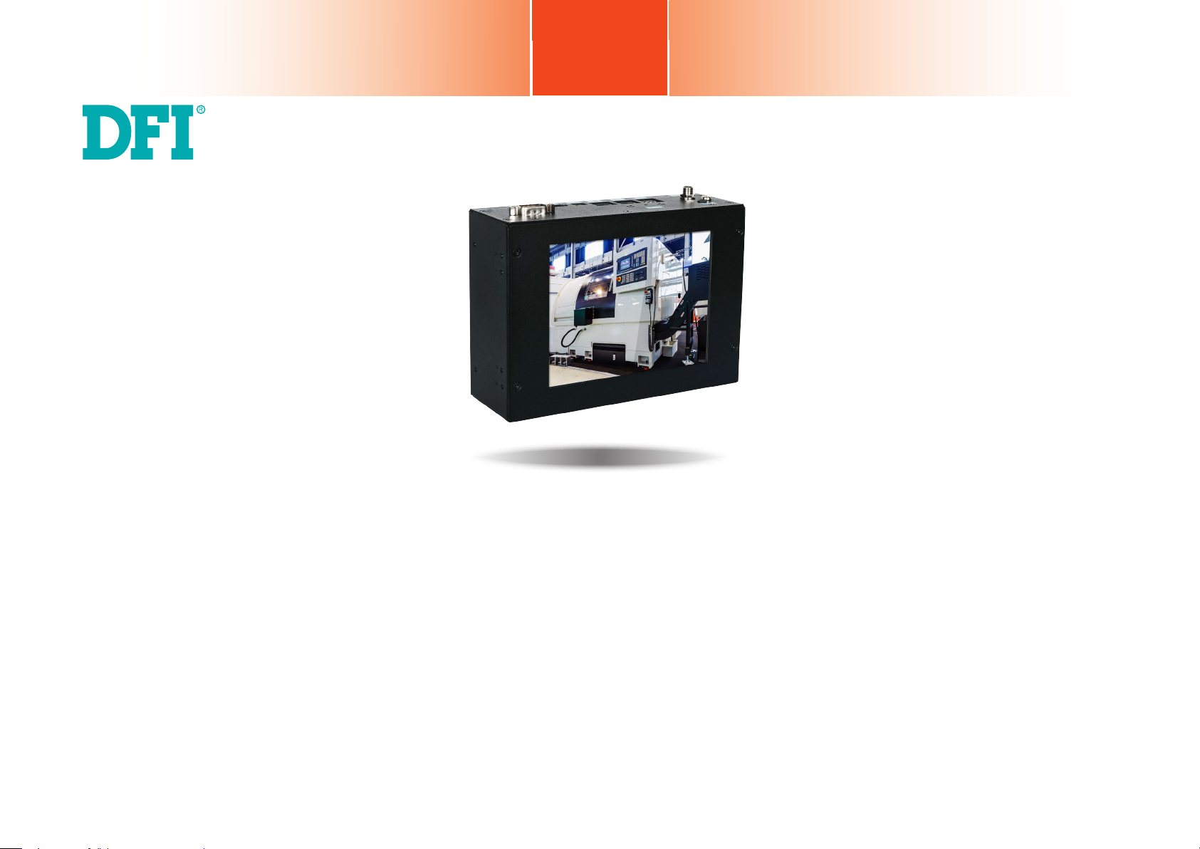
KS057R-FS
5.7” Fanless Touch Panel PC
User’s Manual
A54000929
1
Chapter 1 Introduction
www.d.com
Page 2

Copyright
FCC and DOC Statement on Class A
This publication contains information that is protected by copyright. No part of it may be reproduced in any form or by any means or used to make any transformation/adaptation without
the prior written permission from the copyright holders.
This publication is provided for informational purposes only. The manufacturer makes no
representations or warranties with respect to the contents or use of this manual and specifically disclaims any express or implied warranties of merchantability or fitness for any particular
purpose. The user will assume the entire risk of the use or the results of the use of this document. Further, the manufacturer reserves the right to revise this publication and make changes
to its contents at any time, without obligation to notify any person or entity of such revisions
or changes.
Changes after the publication’s first release will be based on the product’s revision. The website
will always provide the most updated information.
© 2019. All Rights Reserved.
Trademarks
Product names or trademarks appearing in this manual are for identification purpose only and
are the properties of the respective owners.
This equipment has been tested and found to comply with the limits for a Class A digital
device, pursuant to Part 15 of the FCC rules. These limits are designed to provide reasonable protection against harmful interference when the equipment is operated in a residential
installation. This equipment generates, uses and can radiate radio frequency energy and, if not
installed and used in accordance with the instruction manual, may cause harmful interference
to radio communications. However, there is no guarantee that interference will not occur in a
particular installation. If this equipment does cause harmful interference to radio or television
reception, which can be determined by turning the equipment off and on, the user is encouraged to try to correct the interference by one or more of the following measures:
• Reorient or relocate the receiving antenna.
• Increase the separation between the equipment and the receiver.
• Connect the equipment into an outlet on a circuit different from that to which the receiver
is connected.
• Consult the dealer or an experienced radio TV technician for help.
Notice:
1. The changes or modifications not expressly approved by the party responsible for compli-
ance could void the user’s authority to operate the equipment.
2. Shielded interface cables must be used in order to comply with the emission limits.
Chapter 1 Introduction
2
www.d.com
Page 3

Table of Contents
Copyright ............................................................................2
Trademarks .........................................................................2
FCC and DOC Statement on Class A ....................................2
About this Manual ...............................................................4
Warranty ...........................................................................4
Static Electricity Precautions ................................................4
Safety Measures..................................................................4
Safety Precautions ..............................................................5
About the Package ..............................................................5
Chapter 1 - Introduction ......................................................6
Overview .................................................................................6
Key Features ...........................................................................6
Specifications ...........................................................................7
Getting to Know the KS057R-FS ...............................................8
Mechanical Dimensions ............................................................9
Graphics Interface ......................................................................................13
RJ45 LAN Ports ........................................................................................... 14
9~36V DC-in ............................................................................................. 14
USB Ports ................................................................................................... 15
Serial Port .................................................................................................. 15
I/O Connectors ........................................................................................... 16
Expansion Slots .......................................................................................... 16
Debug Connectors ..................................................................................... 16
Front Panel Connector ................................................................................ 17
Battery ....................................................................................................... 17
Chapter 6 - Mounting Options ...........................................20
Din-rail Mount ........................................................................20
Wall Mount ............................................................................20
Chapter 7 - Software Features ...........................................21
Chapter 2 - Getting Started ...............................................10
Chapter 3 - Installing Devices ............................................11
Removing the Chassis Cover ...................................................11
Installing a Mini PCIe Card ..................................................... 11
Chapter 4 - Jumper Settings ..............................................12
Boot Mode Select ...................................................................12
Chapter 5 - Ports and Connectors ......................................13
Panel I/O Ports ........................................................................................... 13
Chapter 1 Introduction
3
www.d.com
Page 4

About this Manual
An electronic file of this manual may be included in a support DVD. If not, you can download
it and other product related documentation from our website at www.dfi.com.
Warranty
1. Warranty does not cover damages or failures that arised from misuse of the product,
inability to use the product, unauthorized replacement or alteration of components and
product specifications.
2. The warranty is void if the product has been subjected to physical abuse, improper installation, modification, accidents or unauthorized repair of the product.
3. Unless otherwise instructed in this user’s manual, the user may not, under any circumstances, attempt to perform service, adjustments or repairs on the product, whether in or
out of warranty. It must be returned to the purchase point, factory or authorized service
agency for all such work.
4. We will not be liable for any indirect, special, incidental or consequential damages to the
product that has been modified or altered.
Static Electricity Precautions
It is quite easy to inadvertently damage your PC, system board, components or devices even
before installing them in your system unit. Static electrical discharge can damage computer
components without causing any signs of physical damage. You must take extra care in handling them to ensure against electrostatic build-up.
1. To prevent electrostatic build-up, leave the system board in its anti-static bag until you are
ready to install it.
2. Wear an antistatic wrist strap.
3. Do all preparation work on a static-free surface.
4. Hold the device only by its edges. Be careful not to touch any of the components, contacts
or connections.
5. Avoid touching the pins or contacts on all modules and connectors. Hold modules or connectors by their ends.
Important:
Electrostatic discharge (ESD) can damage your processor, disk drive and other components. Perform the upgrade instruction procedures described at an ESD workstation only. If such a station is not available, you can provide some ESD protection by
wearing an antistatic wrist strap and attaching it to a metal part of the system chassis. If a wrist strap is unavailable, establish and maintain contact with the system
chassis throughout any procedures requiring ESD protection.
Safety Measures
Chapter 1 Introduction
To avoid damages to the system:
• Use the correct AC input voltage range.
To reduce the risk of electric shock:
• Unplug the power cord before removing the system chassis cover for installation or servic-
ing. After installation or servicing, cover the system chassis before plugging the power cord.
Battery:
• Danger of explosion if battery incorrectly replaced.
• Replace only with the same or equivalent type recommend by the manufacturer.
• Dispose of used batteries according to local ordinance.
4
www.d.com
Page 5

Safety Precautions
About the Package
• Use the correct DC input voltage range.
• Unplug the power cord before removing the system chassis cover for installation or servicing. After installation or servicing, cover the system chassis before plugging the power cord.
• Danger of explosion if battery incorrectly replaced.
• Replace only with the same or equivalent type recommend by the manufacturer.
• Dispose of used batteries according to local ordinance.
• Keep this system away from humidity.
• Place the system on a stable surface. Dropping it or letting it fall may cause damage.
• The openings on the system are for air ventilation to protect the system from overheating.
DO NOT COVER THE OPENINGS.
• Place the power cord in such a way that it will not be stepped on. Do not place anything on
top of the power cord. Use a power cord that has been approved for use with the system
and that it matches the voltage and current marked on the system’s electrical range label.
• If the system will not be used for a long time, disconnect it from the power source to avoid
damage by transient overvoltage.
• If one of the following occurs, consult a service personnel:
- The power cord or plug is damaged.
- Liquid has penetrated the system.
- The system has been exposed to moisture.
The package contains the following items. If any of these items are missing or damaged,
please contact your dealer or sales representative for assistance.
• One 5.7” Touch Panel PC
• One
sheet of poron foam
Optional Items
• Wall mount kit
• Wi-Fi kit
• Power adapter (60W, 12V/5A, Level 6, RoHS)
• Power cord
The board and accessories in the package may not come similar to the information listed
above. This may differ in accordance to the sales region or models in which it was sold. For
more information about the standard package in your region, please contact your dealer or
sales representative.
- The system is not working properly.
- The system dropped or is damaged.
- The system has obvious signs of breakage.
• The unit uses a three-wire ground cable which is equipped with a third pin to ground the
unit and prevent electric shock. Do not defeat the purpose of this pin. If your outlet does
not support this kind of plug, contact your electrician to replace the outlet.
• Disconnect the system from the DC outlet before cleaning. Use a damp cloth. Do not use
liquid or spray detergents for cleaning.
Chapter 1 Introduction
5
www.d.com
Page 6
Chapter 1 - Introduction
Overview
KS057R-FS
Status LED
(green)
Connector Panel
Grounding
USB 2.0
DC-in
Reset
COM (RS485)
LAN 2 LAN 1
(GbE) (GbE)
Chapter 1
Key Features
Model Name KS057R-FS
Processor NXP i.MX6 Cortex-A9 DualLite, 1.0 GHz
LAN Two LAN ports on the connector panel
COM Two COM ports (via DB-9 & terminal block) on the connector panel
Display HDMI port on the connector panel
USB Two USB 2.0 ports (type A)
COM (RS232)
HDMI
Side View
Chapter 1 Introduction
Antenna hole
Antenna hole
6
www.d.com
Page 7
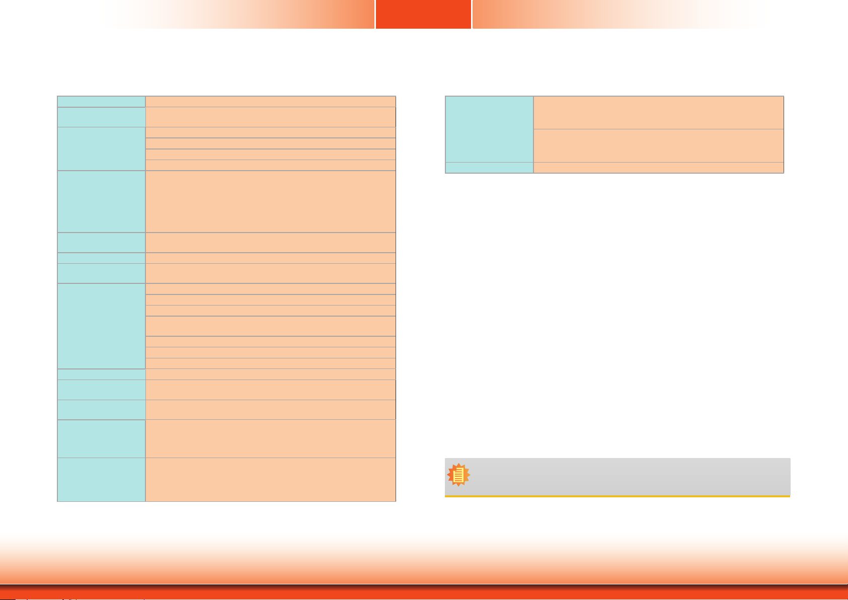
Specifications
Chapter 1
Processor NXP i.MX6 Cortex-A9 DualLite, 1.0 GHz
Memory 1GB SDRAM memory down
Display and Touch
Screen
Graphics • HDMI
Storage 4MB NOR Flash
Expansion 1 x Full-size Mini PCIe (PCIe/USB)
Ethernet Controller 1 x ATHEROS AR8033 Ethernet Controller (10/100/1000Mbps)
I/O Ports 2 x GbE (RJ-45) (10/100/1000Mbps)
Watchdog Timer System Reset, Programmable via Software from 1 to 255 Seconds
Power Type:12V DC
OS Support Yocto 1.8 (default preloaded on eMMC)
Mechanism Construction: sheet metal
Environment Operating Temperature: -20 to 60°C (with extended temperature
Single Channel DDR3L 1600MHz
• Display: 5.7” 640x480 TFT LCD Panel with Resistive Touch Screen
• Brightness: 400 cd/m²
• Contrast: 800:1
• Backlight Lifetime: 50,000 hours
- HDMI 1.4: resolution up to 1920x1080 @ 60Hz
• Single Display
- Yocto: HDMI or LVDS (default)
• Dual Display
- Android: HDMI + LVDS (available upon request)
8GB/16GB eMMC
1 x LAN7500 Ethernet Controller (10/100/1000Mbps)
2 x USB 2.0 (type A)
2 x Wi-Fi Module Antenna Hole
1 x RS-485
1 x RS-232
1 x DC-in connector
1 x Reset switch
1 x HDMI
Connector: DC Jack
Android 5.1.1
Mounting: Wall, Din-rail*
Weight: TBD
Dimensions (W x H x D): 170.2mm x 121mm x 57.5mm
peripherals, ambient with air ow)
Storage Temperature: -30 to 80°C
Relative Humidity: 5 to 90% RH (non-condensing)
Tests and
Certication
Certications CE, FCC Class A
Note:
*Optional items are not supported in standard model. Please contact your sales representative for more information.
• Shock
OP: Half-sine, 3G @ 11ms
Non-OP: Half-sine, 5G @ 11ms
• Vibration
OP: Random, 1Grms @ 5~500Hz, 30min
Non-OP: Sweep sine, 3Grms @ 10~500Hz, 30min
Chapter 1 Introduction
7
www.d.com
Page 8

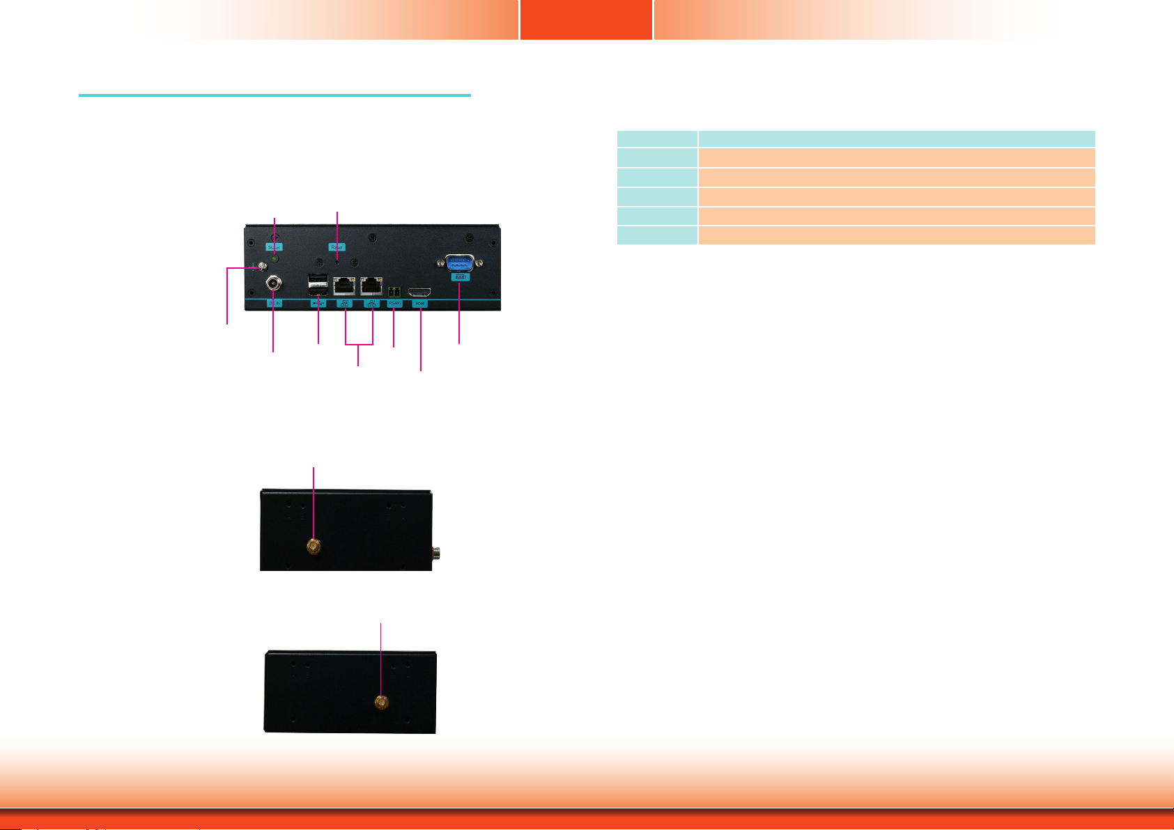
Getting to Know the KS057R-FS
Chapter 1
Connector Panel View
Status LED
(green)
Grounding
DC-in
DC-in
Plug a power adapter into this socket. The acceptable power voltage/type is 12V/DC.
Status (green)
Shows the status of the system.
USB 2.0 Ports
Connect USB 3.0, USB 2.0 or 1.1 devices.
USB 2.0
Reset
LAN 2 LAN 1
(GbE) (GbE)
COM (RS485)
HDMI
COM (RS232)
Side View
Wireless Antenna Holes
Reserved for installing wireless antennas.
Antenna hole
Antenna hole
HDMI Port
Connects the HDMI port of a display.
COM Ports
One RS232 (DB-9 connector) and one RS485 (two-pin terminal) port.
LAN Ports
Connect a network device or an Ethernet cable for network connectivity.
Reset Switch
Press to restart the system without turning off the power.
Chapter 1 Introduction
8
www.d.com
Page 9

Mechanical Dimensions
Chapter 1
Top View
Right View
Front View
Bottom View
170.20
57.50
121.00
Chapter 1 Introduction
9
www.d.com
Page 10

Chapter 2
Chapter 2 - Getting Started
Preparing the System
Before you start using the system, you need the following items:
• AC power adapter
Installing Devices
The following devices can be installed in the system.
• Mini PCIe card
Installing an Operating System
The device platform is an embedded system with Yocto 1.8 beta or Android 5.1 beta preloaded on the eMMC.
Chapter 2 Getting Started
10
www.d.com
Page 11

Chapter 3
Chapter 3 - Installing Devices
Removing the Chassis Cover
Please observe the following guidelines and follow the procedure to open the system.
1. Make sure the system and all other peripheral devices connected to it have been powered
of f.
2. Disconnect all power cords and cables.
3. The 4 mounting screws attached touchscreen cover and the 6 screws on the sides of the
system are used to secure the touch panel to the chassis. Remove these screws and put
them in a safe place for later use. Be careful when opening the touch panel to avoid pulling
the connecting cables apart.
Mounting screw
Installing a Mini PCIe Card
The system board is equipped with 1 full-size Mini PCIe slot that supports both PCIe and USB signals.
1. Grasp the Mini PCIe card by its edges and align the notch of the card with the key in the
connector on the system board.
Mini PCIe socket
Mounting screw
4. Lift the cover to open the system. The Mini PCIe socket is readily accessible after removing
the top cover.
Mounting screw
Mounting screw
Chapter 3 Installing Devices
2. Push down on the other end of the Mini PCIe card and use the provided mounting screw to
secure the card on the system board.
Antenna hole
Note:
If installing a wireless module, place the antenna cable(s) on top of the Mini PCIe and
route the cables to the side of the chassis to reach the antenna holes.
11
www.d.com
Page 12

Chapter 4 - Jumper Settings
9
1
5 9
1
Boot Mode Select
Chapter 4
10
Debug LED
DDR3L
1
JTAG
1
2
5
1
2
1
USB 2.0
USB 3
5
USB OTG
Mini
PCIe
4
1
9
DIODebug
LVDS LCD Panel
DC-in
USB 2.0
USB 1-2
LAN 2
LAN 1
COM 1
HDMI
Panel Backlight/SATA Power
DDR3L
1
Battery
To select the boot mode and boot device, please use dip switch SW5.
Front
Panel
microSD
1
14
eMMC
DDR3L
COM 3
NXP
i.MX6
Cortex-A9
2
I C
DDR3L
1 5
ON
1 2 3 4 5 6 7 8
Boot Mode/Device Select
(SW5)
SW5
1 2 3 4 5 6 7
Boot Mode Select SW5
Boot from the fuses 7 Off, 8 Off
Serial downloader 7 On, 8 Off
Boot from the board settings (default) 7 Off, 8 On
Reserved 7 On, 8 On
Boot Device Select SW5
1 2 3 4 5 6 7 8
eMMC On On Off Off On On Off On
SPI xx xx xx On On Off Off On
SD On Off On Off Off On Off On
8
Chapter 4 Jumper Settings
Note:
SW5 switch is located on the back side of the system board. It is for development and
troubleshooting which should only be performed by developers and service technicians
who are fully aware of the outcome of any changes to the settings.
12
www.d.com
Page 13

Chapter 5 - Ports and Connectors
COM 1
HDMI
Panel I/O Ports
Status LED
(green)
Reset
Chapter 5
Graphics Interface
The system has one display port:
• HDMI port
JTAG
2
1109
5
1
2
Panel Backlight/SATA Power
1
5
USB OTG
USB 3
USB 2.0
Debug LED
Mini
PCIe
DDR3L
9
DIODebug
1
4
1
Grounding
USB 2.0
DC-in
COM (RS485)
LAN 2 LAN 1
(GbE) (GbE)
The front panel I/O consists of the following ports:
• DC-in connector
• Status LED (green)
• Reset button
• Two USB 2.0 ports
• Two Gigabit LAN ports
• COM ports:
- RS232 port
- RS485 port
• HDMI port
HDMI
COM (RS232)
DC-in
USB 2.0
USB 1-2
LAN 2
LAN 1
DDR3L
1
Battery
HDMI
The HDMI port which carries both digital audio and video signals is used to connect the HDMI
port of an LCD monitor or a digital TV.
The system supports dual and triple display with these ports.
Chapter 5 Ports and Connectors
13
Page 14

Chapter 5
9
COM 1
HDMI
9
COM 1
HDMI
RJ45 LAN Ports
1
5
2
10
JTAG
DC-in
USB 2.0
Panel Backlight/SATA Power
USB 1-2
9~36V DC-in
2
1
1
LAN 2
LAN 2
5
USB OTG
USB 3
USB 2.0
Debug LED
LAN 1
Mini
PCIe
DDR3L
DDR3L
9
DIODebug
1
4
1
1
Battery
LAN 1
1
5
1
2
10
JTAG
Panel Backlight/SATA Power
DC-in
USB 2.0
USB 1-2
LAN 2
2
1
5
USB OTG
USB 3
USB 2.0
Debug LED
LAN 1
Mini
PCIe
DDR3L
DDR3L
9
DIODebug
1
4
1
1
Battery
Features
• 2 LAN ports built on Atheros AR8033-AL1B (10/100/1000Mbps) and Microchip LAN7500ABZJ (10/100/1000Mbps)
LAN 1: Atheros Ethernet PHY AR8033-AL1B (10/100/1000Mbps)
This 2-pin terminal block is considered a low power solution. This connector is wired as an
external DC-in connector and reset button for power control. Please note that using a voltage
more than the recommended range may fail to boot the system or cause damage to the system board.
LAN 2: Microchip USB to Ethernet Controller LAN7500-ABZJ (10/100/1000Mbps)
The reset button allows you to reboot the system without powering off the system first.
The LAN ports enable the system board to connect to a local area network with a
network hub.
14
Chapter 5 Ports and Connectors
Page 15

Chapter 5
Panel Backlight/SATA Power
5
1
DC-in
USB 1-2
USB 2.0
1
10
9
2
JTAG
Mini
PCIe
Battery
1
1
9
DIO
Debug
1
4
DDR3L
DDR3L
Debug LED
1
5
2
USB 3
USB 2.0
USB OTG
COM 1
HDMI
LAN 2
LAN 1
COM 1
HDMI
USB Ports
JTAG
DC-in
1109
2
USB 2.0
2
1
5
1
Panel Backlight/SATA Power
USB 2.0
USB 1-2
LAN 2
5
USB OTG
USB 3
USB 2.0
Debug LED
LAN 1
Mini
PCIe
DDR3L
DDR3L
9
DIODebug
1
4
1
1
Battery
Serial Port
COM 1: RS485
1 2
Front
Panel
microSD
eMMC
LVDS LCD Panel
1
14
9
COM 3: RS232
1
5 9
DDR3L
1
COM 3
NXP
i.MX6
Cortex-A9
2
I C
1 5
1
2
DDR3L
ON
1 2 3 4 5 6 7 8
Boot Mode/Device Select
(SW5)
The USB 2.0 ports (USB 1, 2 and 3) and OTG connector are used for USB communication. In
addition, the USB OTG allows the board and the devices connected to it to switch back and
forth between the roles of host and device.
The COM 1 port provides 2-wire RS485 communication with support for auto flow control. And
COM 3 provides standard RS232 communication.
When the system board is in host mode, it acts as a computer and allows USB peripherals to
be connected through the USB OTG port. When the system board is in device mode, it acts as
a peripheral device connecting to a host computer. And in this mode, the system board can
read and write to the onboard eMMC memory from your host computer by using a micro-B
type USB cable.
Chapter 5 Ports and Connectors
Pin Pin Name
1
2
3
4
5
5V
Data-
Data+
GND
NC
15
COM 1
RS485+
RS485-
COM 3
DCD
RXD
TXD
1
2 3 4
8
7
6
RTS
DSR
CTS
DTR
GND
5
Page 16

Chapter 5
9
9
I/O Connectors
Expansion Slots
DC-in
USB 2.0
USB 1-2
LAN 2
LAN 1
COM 1
HDMI
DDR3L
1
Battery
10
JTAG
2
Panel Backlight/SATA Power
Debug LED
USB 2.0
USB 3
USB OTG
DDR3L
4
1
1
DIODebug
Debug Connectors
1
5 9
Front
1
5
1
1
5
Mini
PCIe
9
Panel
microSD
eMMC
2
LVDS LCD Panel
1
14
DDR3L
1
COM 3
NXP
i.MX6
Cortex-A9
2
I C
DDR3L
1 5
ON
1 2 3 4 5 6 7 8
Boot Mode/Device Select
(SW5)
9
10
JTAG
DC-in
USB 2.0
2
1
COM 1
HDMI
4
1
Debug
USB 1-2
LAN 2
LAN 1
Panel Backlight/SATA Power
DDR3L
1
Battery
Debug LED
DDR3L
1
10
JTAG
1
2
5
1
2
1
USB 2.0
USB 3
5
USB OTG
Mini
PCIe
4
1
9
DIODebug
Mini PCI Express Slot
The full-size Mini PCIe socket supports PCIe x1 signals and is used to install a Mini PCIe card.
microSD Socket (on the back side)
The microSD socket allows you to install a microSD card for the expansion of storage.
Chapter 5 Ports and Connectors
The JTAG and debug connectors are used for debugging purposes.
Debug Connector
Pin Pin Name
1
3.3V
2
UART5_RX
UART5_TX
3
GND
4
16
JTAG Connector
Pin Pin Name Pin Pin Name
3.3V
1
GND
3
GND
5
JTAG_MOD
7
JTAG_nTRST
9
2
4
6
8
10
JTAG _TMS
JTAG_TCK
JTAG_TDO
JTAG_TDI
JTAG_nRESET
Page 17

Chapter 5
9
Battery
DIODebug
Front Panel Connector
Front
Panel
5
6
Status LED
1
2
Front
Panel
microSD
eMMC
LVDS LCD Panel
1
14
1
5 9
DDR3L
1
COM 3
NXP
i.MX6
Cortex-A9
2
I C
DDR3L
1 5
ON
1 2 3 4 5 6 7 8
Boot Mode/Device Select
(SW5)
Battery
GND
+3.3V
10
Debug LED
DDR3L
4
1
1
JTAG
USB 2.0
USB 3
2
USB OTG
9
5
1
Mini
PCIe
1
2
1
5
DC-in
USB 2.0
USB 1-2
LAN 2
LAN 1
COM 1
HDMI
2
Battery
1
Panel Backlight/SATA Power
DDR3L
1
Connect to the battery connector
The front panel connector includes a reset button and a power LED.
Pin Pin Name Pin Pin Name
NC
1
GND
3
Reset Button
5
Chapter 5 Ports and Connectors
2
4
6
Power_LED
NC
NC
Battery
The lithium ion battery powers the real-time clock and CMOS memory. It is an auxiliary source
of power when the main power is shut off.
Safety Measures
• Danger of explosion if battery incorrectly replaced.
• Replace only with the same or equivalent type recommend by the manufacturer.
• Dispose of used batteries according to local ordinance.
17
Page 18

Chapter 6
186.00
95.80
Chapter 6 - Mounting Options
Din-rail Mount
Note:
The system unit used in the following illustrations may not resemble the actual one.
These illustrations are for reference only.
The DIN-rail mount kit includes the following:
• DIN-rail mount brackets
• 4 bracket screws
1. Use the provided mounting screws to attach the DIN-rail mount brackets to the rear side of
the device. Note that the connector panel should be at the bottom.
Din-rail mount bracket
Wall Mount
The wall mount kit includes the following:
• 2 wall mount mount brackets
• 4 bracket screws
1. Use the provided mounting screws to attach wall mount brackets to both sides of the device.
The following pictures show the two ways in which the brackets can be attached.
1. Flush with the rear side
2. Flush with the front panel
Mounting screws
2. Install the device onto the rail.
Chapter 6 Mounting Options
2 Fix the device on the wall. The following picture shows the dimensions and location of wall
mount screw holes.
170.20
121.00
Unit: mm
18
www.d.com
Page 19

Chapter 7
Chapter 7 - Software Features
The platform is an embedded system that may be pre-loaded with Yocto 1.8 beta or Android
5.1 beta on the eMMC. This section describes the supported software features of this embedded system.
Yocto Support
Component Support Status
General Support
Component Name Base-Line Feature
General
Misc
(*) This feature depends on NXP’s support.
OS Support
Firmware Upgrade (*) MFGTool rmware update tool
Utilities (*) Hardware diagnostic utilities
Yocto 1.8 - Kernel 3.14.52 (default preloaded on eMMC)
Android 5.1.1 - Kernel 3.14.52
Linux Support
Component Description Detail
It is an open-source project that delivers a
Linux
Linux
AP/API
Yocto 1.8 - Kernel 3.14.52
NXP i.MX6 Yocto 1.8 BSP
Support X11 Window
Support BitBake build tool
Support I2C, Watchdog and GPIO Provide support console for i.MX6 platform
set of tools which create operating system
images for embedded Linux systems.
Support X-11 Demo Image Only (*)
All library and utility should support (*).
Source code package (support by request)
Yocto Version
Kernel Version
Window System
eMMC
Ethernet LAN1
Ethernet LAN2
USB 2.0
USB OTG
HDMI Video
Output
DIO
Mini PCIe
1.8
3.14.52
X11 without QT5 build
Support eMMC boot, eMMC v5.1, Linux ext3 le system
Support "ping", "ifcong" console commands verify, static IP/DHCP
Dynamic IP, xed MAC address.
Support "ping", "ifcong" console commands verify, static IP/DHCP
Dynamic IP, xed MAC address. Due to LAN7500 is PCIe over USB2.0
Ethernet card, data transfer throughput limit is below 480Mbps (USB2.0
SPEC limitation).
1. Support USB HID Keyboard and Mouse Device
2. Support USB Mass Storage by "mount" console command, EXT3/EXT4/
FAT lesystem
1. Support USB HID Keyboard and Mouse Device
2. Support USB Mass Storage by "mount" console command, EXT3/EXT4/
FAT lesystem
3. Support connect to PC to update image by i.MX6 MFGTool
Support single display function, need to plug in HDMI cable before power
on, resolution 1920x1080@60
Support read input voltage, set outpout voltage high/low status, control
by Linux device node, 4 pins
Support "lspci" console command for check PCIe card status. For standard
product, we only port ENLi AP12356 WiFi/BT module.
Android
Android
AP/API
(*) This feature depends on NXP’s support.
Android 5.1.1 - Kernel 3.14.52 Support Demo Image
NXP i.MX6 Android 5.1.1 NXP BSP
Support Android AOSP launcher
Support Android ADB shell
Support Android APK install
Support I2C, Watchdog and GPIO Provide support console for i.MX6 platform.
All library, utility and Android apk should
support (*).
Source code package (support by request)
19
Chapter 7 Supported Software www.d.com
Page 20

Chapter 7
Component Support Status
UART1 - RS485
UART2 - RS422
SPI2 Nor-Flash
RTC
Thermal Sensor
Debug Serial
Port
Play Video
Watchdog
Package
Manager
Support Loopback test, BR 115200 (need DFI Linux user space utility)
Support Loopback test, BR 115200 (need DFI Linux user space utility)
Support SPI2 Nor-Flash boot (Uboot image only)
Support Linux "date -s" and "hwclock -w" console commands to set
system time
Support read device temperature (degrees C) by Linux device node
Suport read Linux kernel debug log by serial port, use PC serial terminal
tool (ex. PuTTY), BR 115200
Support play MPEG4 le (need DFI Linux user space utility).
Support NXP utility "wdt_driver_test.out"(*) to test Watchdog reboot
function
N/A. For standard product, we do not build in package manager.
Android Support
Component Support Status
Android Version
Kernel Version
eMMC
Ethernet LAN1
Ethernet LAN2
USB 2.0
USB OTG
5.1.1
3.14.52
Support eMMC boot, eMMC v5.1, Linux ext4 le system
1. Support "ping", "ifcong" console commands, and NXP Ethernet APP (*)
2. Support static IP/DHCP Dynamic IP, xed MAC address
3. If both LAN1 Ethernet port and LAN2 Ethernet port are plugged-in with
Ethernet cables, only the rst Ethernet port plugged-in with Ethernet
cable will connect to network. If the rst Ethernet port plugged-in with
Ethernet cable is unplugged, the second Ethernet port will connect to
network automatically.
1. Support USB HID Keyboard and Mouse Device
2. Support Android auto mount USB Mass Storage function (only one USB
storage is available at a time. If second USB is plugged-in the USB cable,
second USB is not available. If rst USB is unplugged, second USB needs
to be unplugged and re-plugged back to be available.) FAT32 lesystem
only without multi-partition
3. Support connect to PC to update image by i.MX6 MFGTool
(*) This feature depends on NXP’s support.
20
Chapter 7 Supported Software www.d.com
Page 21

Chapter 7
Component Support Status
HDMI Video
Output
Mini PCIe
UART1 - RS485
UART2 - RS422
SPI2 Nor-Flash
RTC
Thermal Sensor
Debug Serial
Port
Play Video
Watchdog
WiFi/BT
If users want to change HDMI resolution (i.e. 1920x1080), they need
to modify kernel parameter to change LVDS resolution to 1920x1080 too.
1. Support "busybox lspci" console command for check PCIe card status.
2. For standard product, we only port ENLi AP12356 WiFi/BT module.
Support Loopback test, BR 115200 by DFI Android UART demo APP
(supoprt by request)
Support Loopback test, BR 115200 by DFI Android UART demo APP
(supoprt by request)
Support SPI2 Nor-Flash boot (Uboot image only)
Support Android->Settings->Date to set system time function.
Support read device temperature (degrees C) by Android CPU-Z APP
installed by user
Suport read Linux kernel debug log by serial port, use PC serial terminal
tool (ex. PuTTY), BR 115200
Support play MPEG4 le by Android AOSP Gallery APP.
Support adb shell command "am hang --allow-restart" to test Watchdog
reboot function
1. Support AP12356 WiFi/BT module
2. AP12356 WiFi:
(1) Support WiFi STA Mode (connect WiFi AP) by Android UI to enable/
disable it.
(2) Support Soft AP Mode (enable DHCP/IPv4 routing) by Android UI to
enable/disable it.
(3) Support Android UI to set up Soft AP information
(4) Support Android Airplane mode to disable WiFi function
(5) Not support STA mode and Soft AP mode enable at the same time
(6) Not support other WiFi modes, i.e. Wi-Fi Direct, Miracast, Wi-Fi
TimeSYnc, etc.
(7) STA mode limitation: when plug-in wired LAN, STA mode will
disconnect automatically by Android network framework limitation
3. AP12356 BT:
(1) Support BT connected and enable/disable by Android UI
(2) Support BT les transfer by OPP prole using "Bluetooth File
Transfer" tool.
(3) Support OPP, FTP, OBEX, SDAP prole only
(4) Not support other BT proles which are not listed above
(5) Suppot Android Airplane mode to disable BT function
Component Support Status
Android Build
Type
Android ADB
Android Factory
Reset
Android
Fastboot
Android OTA
Android CTS
Android GMS/
GTS
Android Suspend
Preload Android
APPs
(*) This feature depends on the NXP’s support.
ENG Build without SELinux
Support
Support
Not support
Not support
Not support
Not support
Not support suspend, set never to suspend by default.
1. AOSP Browser: Web Browser
2. AOSP Calculator: Calculator APP
3. AOSP Calendar: Calendar APP
4. AOSP Clock: Clock APP, support alarm wake-up
5. AOSP Contacts: function not ready, preload for 3G module test in the
future
6. AOSP Dev Tools: develop test tool
7. AOSP Downloads: show downloads APP
8. AOSP Email: E-Mail APP
9. AOSP Gallery: Gallery APP (JPEG)
10. AOSP Messaging: Short Message Service (SMS) APP. Function not
ready, preload for 3G module test in the future.
11. AOSP Music: Play music APP (MP3)
12. AOSP Phone: function not ready, preload for 3G module test in the
future.
13. AOSP Settings: Android Settings APP
14. AOSP Sound Recorder: Sound Recorder APP. Function not ready,
preload for AOSP Audio module test in the future
15. NXP Audio Route (*): function not ready, preload for Audio module
test in the future.
16. NXP Ethernet (*): Ethernet settings APP.
17. Open-source Simple Explorer: File Explorer APP
21
Chapter 7 Supported Software www.d.com
 Loading...