

Page 1
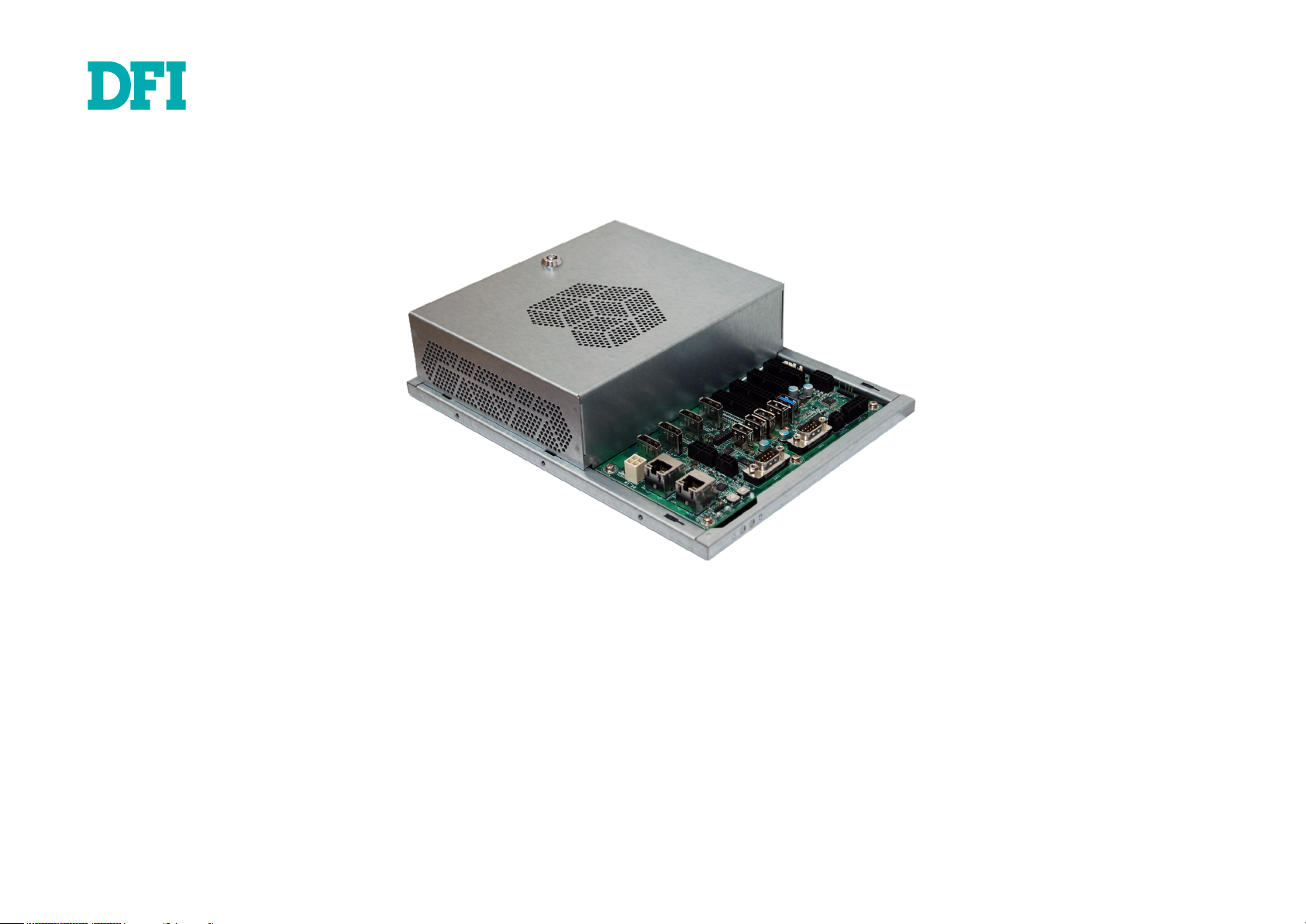
GM341-GHF
Gaming Computing System
User’s Manual
A50110941
Page 2

Copyright
This publication contains information that is protected by copyright. No part of it may be reproduced in any form or by any means or used to make any transformation/adaptation without
the prior written permission from the copyright holders.
This publication is provided for informational purposes only. The manufacturer makes no
representations or warranties with respect to the contents or use of this manual and specifically disclaims any express or implied warranties of merchantability or fitness for any particular
purpose. The user will assume the entire risk of the use or the results of the use of this document. Further, the manufacturer reserves the right to revise this publication and make changes
to its contents at any time, without obligation to notify any person or entity of such revisions
or changes.
Changes after the publication’s first release will be based on the product’s revision. The website
will always provide the most updated information.
© 2019. All Rights Reserved.
FCC and DOC Statement on Class B
This equipment has been tested and found to comply with the limits for a Class B digital
device, pursuant to Part 15 of the FCC rules. These limits are designed to provide reasonable protection against harmful interference when the equipment is operated in a residential
installation. This equipment generates, uses and can radiate radio frequency energy and, if not
installed and used in accordance with the instruction manual, may cause harmful interference
to radio communications. However, there is no guarantee that interference will not occur in a
particular installation. If this equipment does cause harmful interference to radio or television
reception, which can be determined by turning the equipment off and on, the user is encouraged to try to correct the interference by one or more of the following measures:
• Reorient or relocate the receiving antenna.
• Increase the separation between the equipment and the receiver.
• Connect the equipment into an outlet on a circuit different from that to which the receiver
is connected.
• Consult the dealer or an experienced radio TV technician for help.
Trademarks
Product names or trademarks appearing in this manual are for identification purpose only and
are the properties of the respective owners.
Notice:
1. The changes or modifications not expressly approved by the party responsible for compli-
ance could void the user’s authority to operate the equipment.
2. Shielded interface cables must be used in order to comply with the emission limits.
2User's Manual | GM341-GHF
Page 3

Table of Contents
About this Manual .................................... 4
Warranty ................................................. 4
Static Electricity Precautions ..................... 4
Safety Measures....................................... 4
Safety Precautions ................................... 5
About the Package ................................... 5
Before Using the System .......................... 5
Chapter 1 - Introduction ........................... 6
Overview .................................................................................6
Key Features ...........................................................................6
Specifications ...........................................................................7
Getting to Know the GM341-GHF ..............................................8
Mechanical Dimensions ............................................................9
Chassis Dimension ..................................................................9
Chapter 3 - Installing Devices ................... 11
Chapter 4 - Jumper Settings ..................... 14
Clear CMOS Data ................................................................... 14
FPGA Programming Mode Select ............................................. 14
MCU Programming Mode ........................................................ 15
Chapter 5 - Ports and Connectors ............. 16
Audio Ports .............................................................................. 16
USB Ports................................................................................ 17
DC-in ...................................................................................... 17
COM Ports ............................................................................... 18
RJ45 LAN Ports ........................................................................ 19
Intrusion Doors ........................................................................ 19
Display Outputs ....................................................................... 20
Digital Inputs/Outputs .............................................................. 20
Expansion Connectors ............................................................... 22
CPU/System Fan Connector ....................................................... 22
LEDs ....................................................................................... 23
Battery ................................................................................... 23
SATA (Serial ATA) Connectors .................................................... 24
LPC Connector ......................................................................... 24
5V DC-out ............................................................................... 25
Chapter 6 - Mounting ............................... 26
Chapter 7 - BIOS Setup ........................... 27
Chapter 8 - Supported Software ............... 42
Connecting the I/O Board ......................................................11
Powering on the System and Connecting the Display ...............11
Removing the Chassis Cover ...................................................12
Installing the SODIMM ........................................................... 12
Installing an M.2 card ............................................................13
Installing a SATA DOM ........................................................... 13
3User's Manual | GM341-GHF
Page 4
About this Manual
An electronic file of this manual can be obtained from the DFI website at www.dfi.com. To
download the user’s manual from our website, please go to Support > Download Center. On
the Download Center page, select your product or type the model name and click "Search" to
nd all technical documents including the user's manual for a specic product.
Warranty
1. Warranty does not cover damages or failures that arised from misuse of the product,
inability to use the product, unauthorized replacement or alteration of components and
product specifications.
Static Electricity Precautions
It is easy to inadvertently damage your PC, system board, components or devices even before
installing them in your system unit. Static electrical discharge can damage computer components without causing any signs of physical damage. You must take extra care in handling
them to ensure against electrostatic build-up.
1. To prevent electrostatic build-up, leave the system board in its anti-static bag until you are
ready to install it.
2. Wear an antistatic wrist strap.
3. Do all preparation work on a static-free surface.
2. The warranty is void if the product has been subjected to physical abuse, improper installation, modification, accidents or unauthorized repair of the product.
3. Unless otherwise instructed in this user’s manual, the user may not, under any circumstances, attempt to perform service, adjustments or repairs on the product, whether in or
out of warranty. It must be returned to the purchase point, factory or authorized service
agency for all such work.
4. We will not be liable for any indirect, special, incidental or consequential damages to the
product that has been modified or altered.
4. Hold the device only by its edges. Be careful not to touch any of the components, contacts
or connections.
5. Avoid touching the pins or contacts on all modules and connectors. Hold modules or con
nectors by their ends.
Important:
Electrostatic discharge (ESD) can damage your processor, disk drive and other components. Perform the upgrade instruction procedures described at an ESD workstation only. If such a station is not available, you can provide some ESD protection by
wearing an antistatic wrist strap and attaching it to a metal part of the system chassis. If a wrist strap is unavailable, establish and maintain contact with the system
chassis throughout any procedures requiring ESD protection.
Safety Measures
To avoid damage to the system:
• Use the correct AC input voltage range.
To reduce the risk of electric shock:
• Unplug the power cord before removing the system chassis cover for installation or servic-
ing. After installation or servicing, cover the system chassis before plugging the power cord.
Battery:
• Danger of explosion if battery incorrectly replaced.
• Replace only with the same or equivalent type recommend by the manufacturer.
• Dispose of used batteries according to local ordinance.
4User's Manual | GM341-GHF
Page 5

Safety Precautions
• Use the correct DC input voltage range.
• Unplug the power cord before removing the system chassis cover for installation or servicing. After installation or servicing, cover the system chassis before plugging the power cord.
• Danger of explosion if battery incorrectly replaced.
• Replace only with the same or equivalent type recommend by the manufacturer.
• Dispose of used batteries according to local ordinance.
• Keep this system away from humidity.
About the Package
The package contains the following items. If any of these items are missing or damaged,
please contact your dealer or sales representative for assistance.
• GM341-GHF system unit
• Mounting screws for M.2 modules
• CD disk includes
- Manual
- Drivers
• Quick Installation Guide
• Place the system on a stable surface. Dropping it or letting it fall may cause damage.
• The openings on the system are for air ventilation to protect the system from overheating.
DO NOT COVER THE OPENINGS.
• Place the power cord in such a way that it will not be stepped on. Do not place anything on
top of the power cord. Use a power cord that has been approved for use with the system
and that it matches the voltage and current marked on the system’s electrical range label.
• If the system will not be used for a long time, disconnect it from the power source to avoid
damage by transient overvoltage.
• If one of the following occurs, consult a service personnel:
- The power cord or plug is damaged.
- Liquid has penetrated the system.
- The system has been exposed to moisture.
- The system is not working properly.
- The system dropped or is damaged.
- The system has obvious signs of breakage.
• The unit uses a three-wire ground cable which is equipped with a third pin to ground the
unit and prevent electric shock. Do not defeat the purpose of this pin. If your outlet does
not support this kind of plug, contact your electrician to replace the outlet.
• Disconnect the system from the DC outlet before cleaning. Use a damp cloth. Do not use
liquid or spray detergents for cleaning.
The board and accessories in the package may not come similar to the information listed
above. This may differ in accordance to the sales region or models in which it was sold. For
more information about the standard package in your region, please contact your dealer or
sales representative.
Before Using the System
Before powering-on the system, prepare the basic system components.
If you are installing the system for the first time, you will need at least one of the following
internal components.
• Storage devices such as SATA DOMs and M.2 modules.
You will also need external system peripherals, which will normally include at least a keyboard,
a mouse and a video display.
5User's Manual | GM341-GHF
Page 6
Chapter 1 - Introduction
Chapter 1
Chapter 1
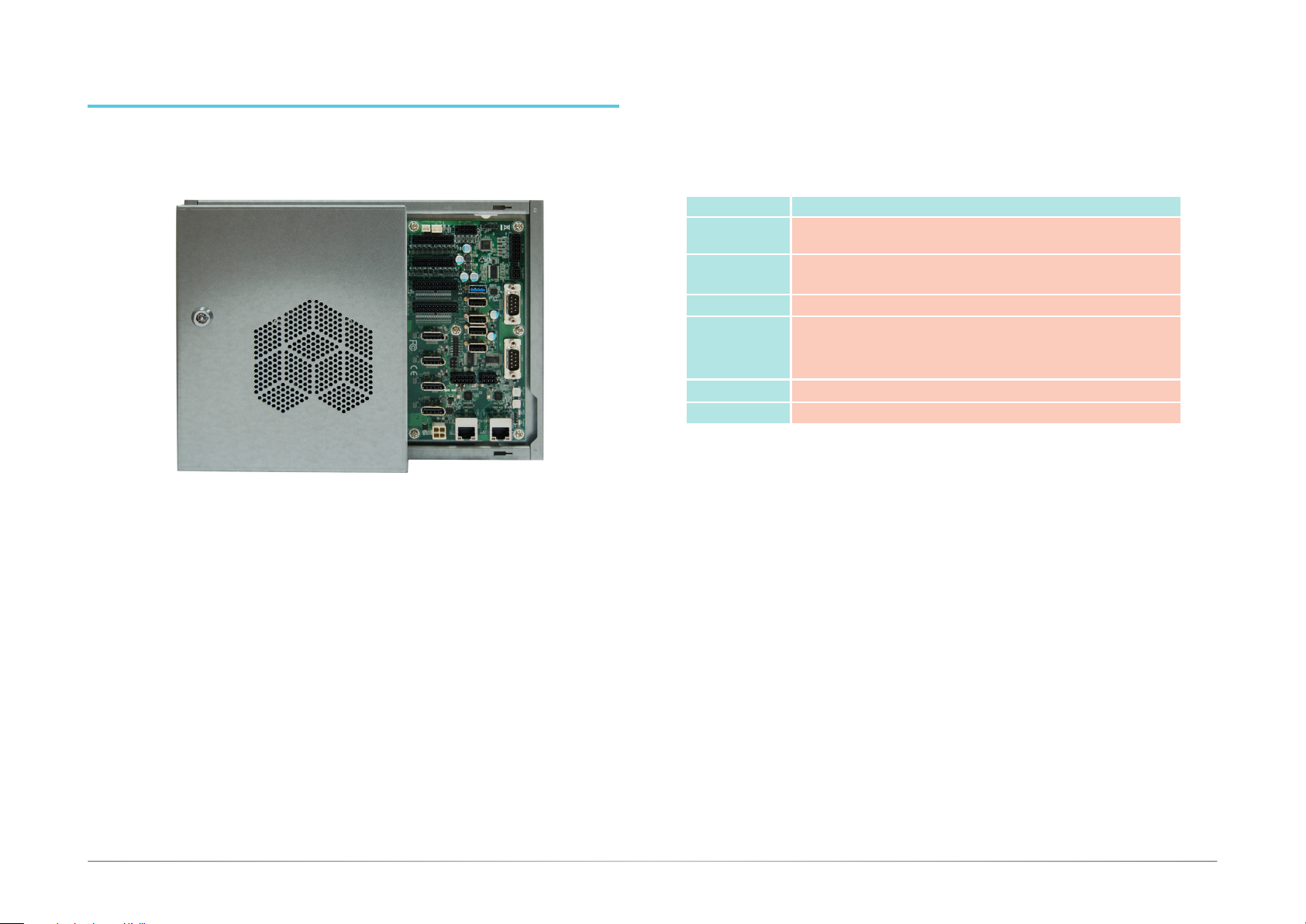
Overview
Key Features
Model Name GM341-GHF
Processor AMD® Ryzen™ V1000 Series, FP5 BGA
AMD® Ryzen™ R1000 Series, FP5 BGA
Audio Speaker and 5.1 Channel Audio Output
S/PDIF Digital Output
LAN Two LAN ports
COM One RS-232 (DB-9 connector)
Display
USB Two USB 3.0 and four USB 2.0 Type A ports
One RS-232/422/485 (DB-9 connector)
One RS-232 (Tx, Rx)/ccTalk (pin headers)
Two RS-232 (Tx, Rx)/SAS/BACTA (pin headers)
Four DP
6User's Manual | GM341-GHF
Page 7
Chapter 1
Specications
Processor System AMD® Ryzen™ Embedded V1807, Quad Core, 2MB Cache, 11 CU,
3.35GHz (3.8GHz), 35-54W
AMD® Ryzen™ Embedded V1756, Quad Core, 2MB Cache, 8 CU,
3.25GHz (3.6GHz), 35-54W
AMD® Ryzen™ Embedded V1605, Quad Core, 2MB Cache, 8 CU,
2.0GHz (3.6GHz), 12-25W
AMD® Ryzen™ Embedded V1202, Dual Core, 1MB Cache, 3 CU,
2.3GHz (3.2GHz), 12-25W
AMD® Ryzen™ R1000 Series
Memory Two 260-pin SODIMM up to 32GB
Dual Channel DDR4 3200MHz
Graphics • AMD® Radeon™ Vega Graphics
• Supported codecs:
OpenGL 4.5, DirectX 12, OpenCL 2.1
HW Decode: AVC/H.264, MPEG2, VC1/WMV9, JPEG/MJPEG,
HEVC/H265, VP8, VP9
HW Encode: MPEG2, AVC/H264, JPEG, HEVC/H265, VP8, VP9
• Display interfaces:
4 x DP++ ( with V1000 series processors) or 3 x DP++ (with
R1000 series processors)
DP: resolution up to 4096x2160 @ 60Hz
Audio 5.1 Channel Audio Output
S/PDIF Digital Output
Stereo 10W+10W Class D Audio AMP Output
Storage/Expansion • 2 x SATA 3.0 (up to 6GB/s) with 7-pin VCC Support
• 1 x M.2 M Key (2280, PCIe x2, only available with Ryzen™
V1000 series processors)
Ethernet 2 x Realtek 8119 or 8111HN (optional) Gigabit Ethernet Controller
Note:
*The mount kit is not supported in the standard model. Please contact your sales
representative for more information.
I/O Ports and LED
Indicators
Power • 12V DC-in (4-pin Vertical Connector)
Environment • Temperature
Vibration • Operation:
Shock • Operation:
Construction
Mounting
Dimensions (W x H x D) • 270mm x 63mm x 210mm (10.63" x 2.48" x 8.27")
Weight • TBD
OS Support Windows 10 (64-bit)
• LEDs
- 1 x Power LED
- 1 x HDD LED
• I/O Ports
1 x RS-232 (DB-9 connector)
1 x RS-232/422/485 (DB-9 connector)
1 x RS-232 (Tx, Rx)/ccTalk (pin header)
2 x RS-232 (Tx, Rx)/SAS/BACTA (pin header)
2 x USB 3.0
4 x USB 2.0
Digital I/O
DI: 1~32
DO: 1~32
Intrusion detection
doors: 1~8
• Button
Power Button
Reset Button
- Operating: 0oC ~ 45oC
- Storage: -20oC ~ 85oC
• Relative Humidity
- 5 to 90% RH (non-condensing)
IEC 60068-2-64 Test Fh: Vibration Board-Band Random Test
Random, 1Grms @ 5~500 Hz, 30min.
• Non-Operation:
IEC 60068-2-6 Test Fc: Vibration Sinusoidal Test
Sweep sine, 3Grms @ 10~500Hz, 30min.
IEC 60068-2-27 Test Ea: Shock test
Half-sine, 3G @ 11ms, 18 Shock ±X, ±Y, ±Z (each axis 3 times)
• Non-Operation:
IEC 60068-2-27 Test Ea: Shock test
Half-sine, 5G @ 11ms, 18 Shock ±X, ±Y, ±Z (each axis 3 times)
• Aluminum + Metal Aluminum
•
Wall mount (*)
Ubuntu 16.04LTS (64-bit)
7User's Manual | GM341-GHF
Page 8
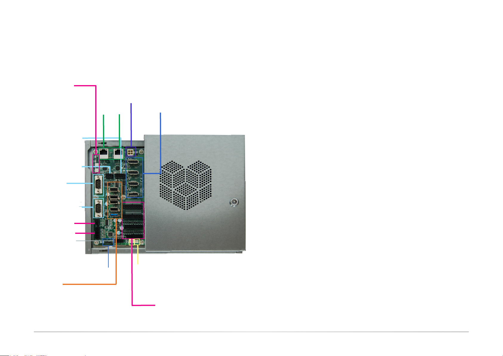
Getting to Know the GM341-GHF
Chapter 1
Chapter 1
Front View
Power LED
HDD LED
Power Button
Reset Button
COM 4/5 RS232
(Tx/Rx/12V/-12V/GND)
COM 3 RS232
(Tx/Rx/GND) or ccTalk
COM 2 (RS232)
COM 1
(RS232/RS422/RS485)
Speaker
5.1 ch audio
Door 1~6
USB Ports
(from top to down):
USB 2_4
USB 2_3
USB 2_2
USB 2_1
USB 3_2
4-pin DC-in
LAN 1 LAN 2
S/PDIF
iButton
Door 7
DP 0
DP 1
DP 2
DP 3
Digital inputs/outputs
(from top to down):
Digital input 1~16
Digital input 17~32
Digital output 1~16
Digital output 17~32
Speaker and 5.1 ch audio
Connects an audio I/O module to the 4-pin speaker connector for stereo (10W+10W) speakers and 5.1 ch audio connector for audio sound systems; there is also an S/PDIF digital audio
connector.
Digital I/O
32 digital inputs via 2x10 micro-fit connector
32 digital outputs via 2x9 micro-fit connector
LAN Ports
Connect the system to a local area network.
DC-in
DC 12V power input via a 4-pin connector.
DP Ports (DP 0~3)
Connect the DisplayPort of a display device.
USB 2.0 & 3.0 Ports
4 USB 2.0 ports and 2 USB 3.0 ports (one in the I/O area and the other in the system area
protected by a cover)
COM ports
COM1 (DB-9): connects RS232/RS422/RS485 devices.
COM2 (DB-9): connects RS232 devices.
COM3: connects RS232 with Tx/Rx/GND or ccTalk
COM4/5: connects RS232 with Tx/Rx/+12V/-12V/GND
Power LED
Indicates the status of the system.
HDD LED
Indicates the status of the storage device.
Power Button
Press to power on or off the system.
Reset Button
Press to reset the system.
Intrusion Doors Connectors
6 doors via a 2x4 micro-fit connector
1 door via a 2-pin box header in the I/O area
1 door via a 2-pin box header in the protected system area
8User's Manual | GM341-GHF
Page 9
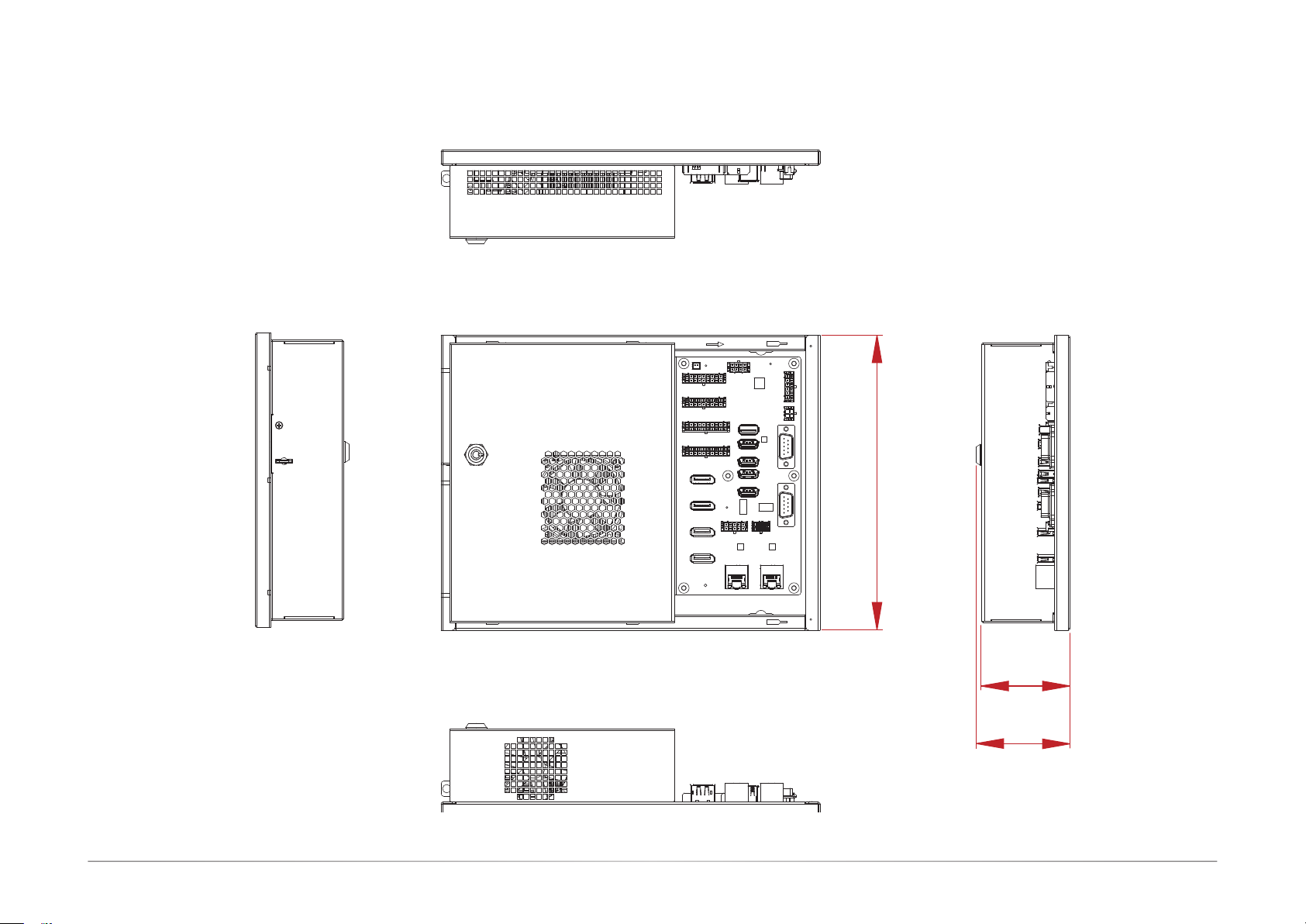
Mechanical Dimensions
Chassis Dimension
Chapter 1
Front View
Left View
Right View
200.00
Top View
63.00
67.00
Rear View
9User's Manual | GM341-GHF
Page 10

Chapter 2
Chapter 2 - Getting Started
Preparing the System
Before you start using the system, you need the following items:
• SATA DOMs or M.2 modules
• USB keyboard
• USB mouse
• CD-ROM drive (for installing software/drivers)
• Screwdriver
• Memory modules
Installing Devices
The following devices can be installed in the system.
• Memory modules
• SATA DOMs
• M.2 modules
Configuring the BIOS
To get you started, you may need to change configurations such as the date, time and the priority of boot devices.
Chapter 2
1. Power on the system.
2. After the memory test, the message “Press DEL to run setup” will appear on the screen.
Press the Delete key to enter the BIOS setup utility.
Installing a Operating System
Most operating system software can be installed using a DVD (and DVD burner) or bootable
USB drive.
Please refer to your operating system manual for instructions on installing an operating system.
Installing the Drivers
The system comes with a software package including drivers. These drivers must be installed to
provide the best system performance. Refer to the Supported Software Chapter for instructions
on installing drivers.
10User's Manual | GM341-GHF
Page 11
Chapter 3
Chapter 3 - Installing Devices
Connecting the I/O Board
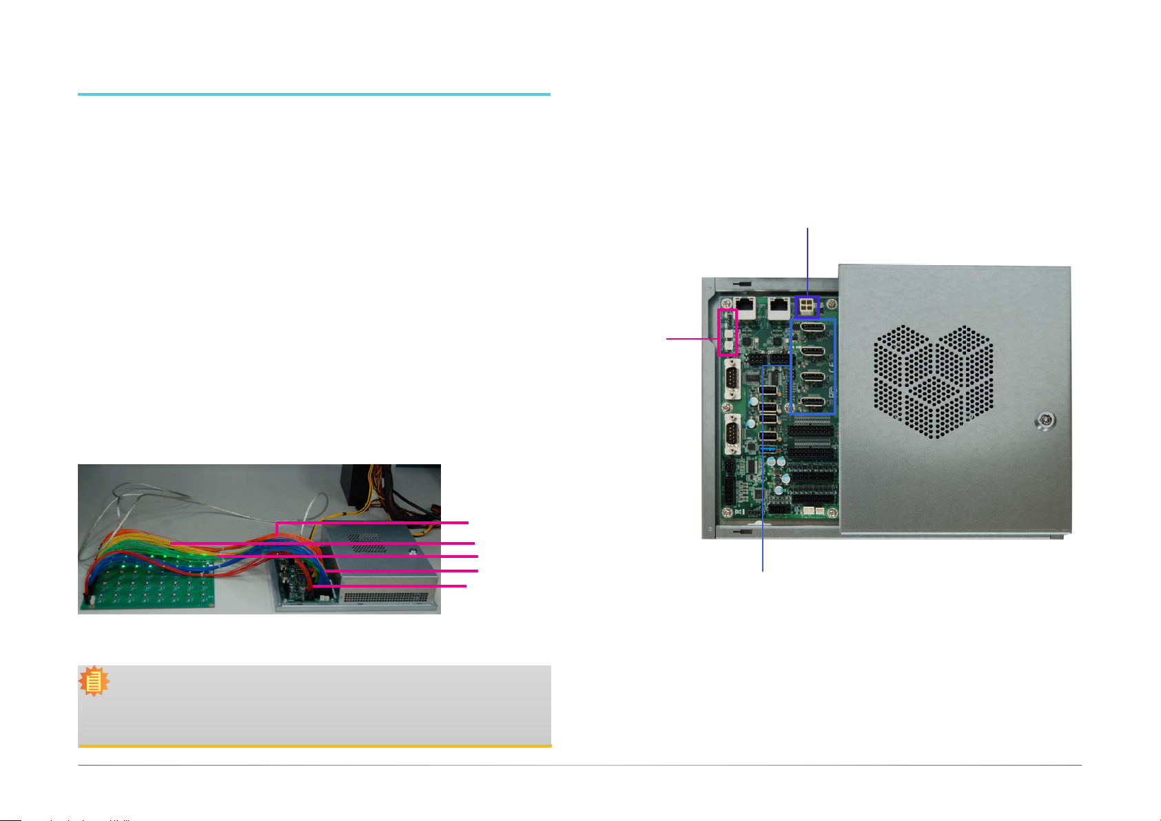
The system supports 32 digital inputs and outputs. The I/O board that came with the package
can be connected to the system to test the digital input and output function. Please observe the
following guidelines and follow the procedure to connect the I/O board.
1. Make sure the system and all other peripheral devices connected to it have been powered off.
2. Disconnect all power cords and cables.
3. Connect one end of the USB cable (type-A connector) to the system and the other end of the
USB cable (type-B connector) to the I/O board.
4. Connect the I/O board to the system's intrusion detection connector (labeled door 1~6) using
the red cable.
5. Connect the I/O board to the system's DIO port (labeled
6. Connect the I/O board to the system's DIO port (labeled
7. Connect the I/O board to the system's DIO port (labeled
8. Connect the I/O board to the system's DIO port (labeled
DO: 17~32)
DO: 1~16)
DI: 17~32)
DI: 1~16)
using the blue cable.
using the green cable.
using the yellow cable.
using the orange cable.
Powering on the System and Connecting the Display
To power on the system, simply connect the 4-pin power cable to the system and the system will
be automatically powered on. If you want to use a power or a reset switch (tact button), they are
located on the system board as shown in the following picture.
To connect the display, use a DisplayPort cable to connect one of the DP ports to a display device.
4-pin DC-in
Power LED
HDD LED
Power Button
Reset Button
Orange DI: 1~16
Yellow DI: 17~32
Green DO: 1~16
Blue DO: 17~32
Red: Door 1~6
Note:
The tact buttons on the I/O board can be used to invoke a door intrusion event or set
the high/low level of a digital I/O port. You can also use the demonstration application
to alter a digital I/O port’s level. For more information, please refer to the software application guide.
DP 0
DP 1
DP 2
DP 3
11User's Manual | GM341-GHF
Page 12
Chapter 3
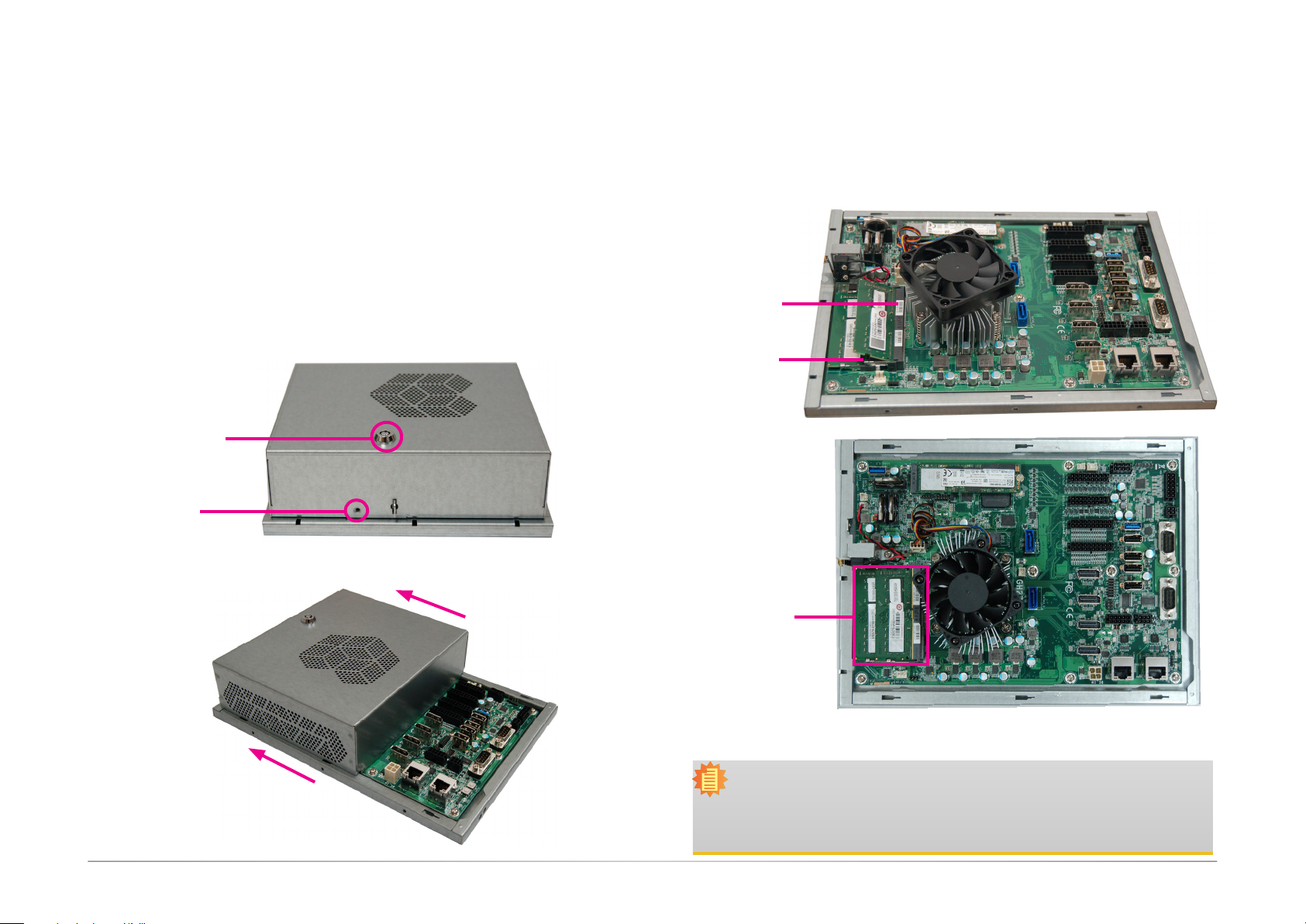
Removing the Chassis Cover
Please observe the following guidelines before opening the chassis cover:
1. Make sure the system and all other peripherals connected to it have been powered off.
2. Disconnect all power cords and cables.
3. The mounting screw on the rear side of the system compartment is used to secure the cover
to the chassis. Remove this screw and put it in a safe place for later use.
4. Use the key (push it down slightly and turn it counterclockwise) to unlock the system compartment cover.
5. Slide the cover backward to open the chassis cover.
Compartment lock
Mounting screw
Installing the SODIMM
Grasp the module by its edges and align the memory’s notch with the socket’s notch;
then insert the memory into the socket at an angle and push it down until you feel a
click.
DDR4_1 Socket
DDR4_2 Socket
SODIMM modules
Notes:
1. The system supports dual-channel configuration. To enable dual-channel,
populate both SODIMM sockets.
2. The SODIMM sockets can only accept DDR4 (3200MHz) memory modules.
Please do not install other types of memory modules.
12User's Manual | GM341-GHF
Page 13
Chapter 3
Installing a SATA DOMInstalling an M.2 card
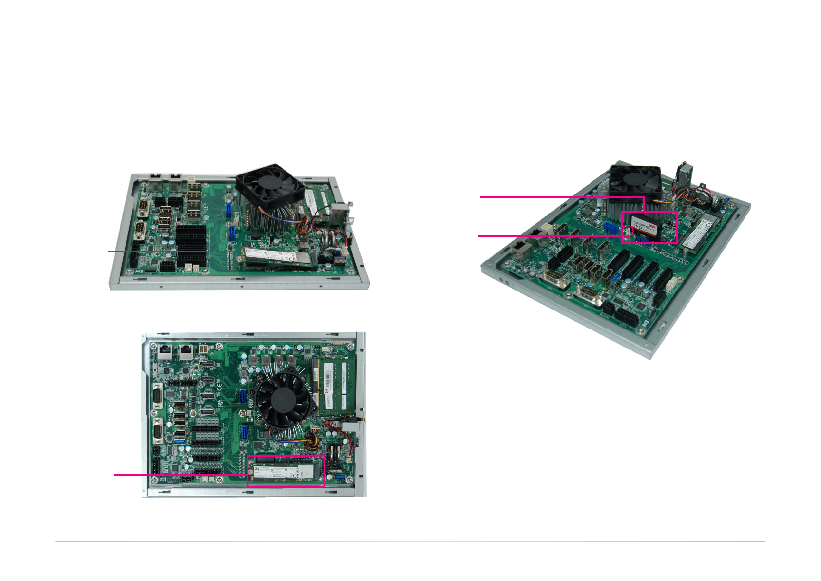
The system (only with the V1000-series CPUs) has one M.2 type 2280 socket (M Key), which
provides PCIe NVMe x2 interface that supports the installation of M.2 22 x 80mm SSD cards:
1. Align the notch at the edge of the M.2 card with the key in the connector.
2. Push down on the other end of the card and use the provided mounting screw (the longer
one) to secure both cards on the system board.
M.2 module
The system board is equipped with two SATA 3.0 ports that support the installation of SATA DOMs
that can be used as a boot drive, system backup and recovery device, etc.
These SATA ports provide power so external power supply is not needed. However, if such power
supply is required, the board is equipped with a 2-pin
port with the connector of a SATA DOM before inserting the SATA DOM.
SATA DOM
DC-out
5V/2A
DC-out connector. Align the SATA
M.2 module
13User's Manual | GM341-GHF
Page 14
System Fan
Door 1~6
System Fan
USB 3.0_1
Door 1~6
Chapter 4 - Jumper Settings
Clear CMOS Data
3
1
L
or
2
Power LED
HDD LED
Power Button
Reset Button
COM 2
1
6
5
COM 1
1
6
5
3
1
Speaker
4
2
17
5.1CH
12
6
6
3
COM 3
S/PDIF
LAN 1
4
1
1
USB 2.0_4
1
USB 2.0_3
1
USB 2.0_2
1
USB 2.0_1
1
USB 3.0_2
10
5
COM 4/5
1
LAN 2
4
4
4
4
4
1
5
Intrusion
4
DC_in
DP 0
6
1
DP 1
1
2
DP 2
LPC
DP 3
20
10
DI 1~16
20
10
DI 17~32
18
9
4
DO 1~16
18
9
DO 17~32
iButton
1
Intrusion
Door7
4
8
SATA 3.0
1
SATA 2
1
DC_out
5V/2A
SATA 3.0
1
11
SATA 1
1
11
Standby Power LED
1
10
1
10
1
SRAM
AMD
Ryzen
V1000Series/
R1000Series
SPI
Flash
FPGA Program (J12)
1
M.2 2280 (M Key)
Only for the V1000 CPU
TM
CPU Fan
MCU Program (J15)
1
Chapter 4
FPGA Programming Mode Select
3
1
L
1
DDR4_2 SODIMM
DDR4_1 SODIMM
1
BAT 2
BAT 3
BAT 1
1
Intrusion
Door 8
1
1
Clear COMS (JP1)
4
Power LED
HDD LED
Power Button
Reset Button
COM 2
1
6
5
COM 1
1
6
5
3
1
Speaker
4
2
17
5.1CH
12
6
6
3
COM 3
S/PDIF
LAN 1
4
1
1
USB 2.0_4
1
USB 2.0_3
1
USB 2.0_2
1
USB 2.0_1
1
USB 3.0_2
10
5
COM 4/5
4
1
LAN 2
4
4
4
4
1
5
Intrusion
or
2
4
DC_in
DP 0
6
1
DP 1
1
2
DP 2
LPC
DP 3
20
10
DI 1~16
20
10
DI 17~32
18
9
4
DO 1~16
18
9
DO 17~32
iButton
1
Intrusion
Door7
4
8
SATA 3.0
1
SATA 2
1
DC_out
5V/2A
SATA 3.0
1
11
SATA 1
1
11
Standby Power LED
1
10
1
10
1
SRAM
AMD
TM
Ryzen
V1000Series/
R1000Series
SPI
Flash
MCU Program (J15)
FPGA Program (J12)
1
M.2 2280 (M Key)
Only for the V1000 CPU
CPU Fan
1
DDR4_2 SODIMM
DDR4_1 SODIMM
1
BAT 2
1
BAT 1
BAT 3
1
USB 3.0_1
Intrusion
Door 8
1
1
Clear COMS (JP1)
4
JP1
3
2
1
1-2 On:
Normal (default)
3
2
1
2-3 On:
Clear CMOS Data
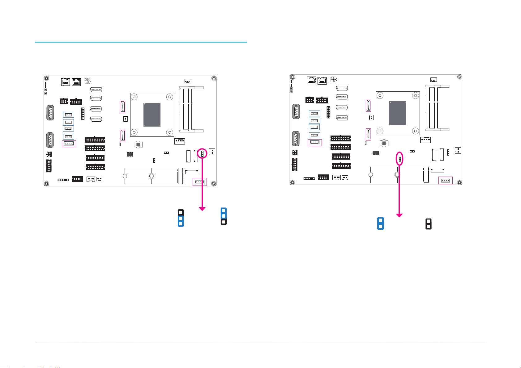
If you encounter the following situations, you can reconfigure the system with the default values stored in the ROM BIOS.
a) CMOS data becomes corrupted.
b) You forgot the supervisor or user password.
To load the default values stored in the ROM BIOS, please follow the steps below.
1. Power-off the system and unplug the power cord.
2. Set the jumper pins 2 and 3 to On. Wait for a few seconds and set the jumper back to its
default setting, pins 1 and 2 On.
3. Now plug the power cord and power-on the system.
J12
1
2
F.W. update programmable
1-2 On:
1
2
None:
Protective mode
J12 is used to select the FPGA programming mode. To enable or disable FPGA programming of
the system board, please set the jumper as indicated above.
14User's Manual | GM341-GHF
Page 15
USB 3.0_1
Door 1~6
Door7
MCU Programming Mode
Chapter 4
Power LED
HDD LED
Power Button
Reset Button
COM 2
1
6
5
COM 1
1
6
5
3
1
Speaker
4
2
17
5.1CH
12
6
6
3
COM 3
S/PDIF
LAN 1
4
1
1
USB 2.0_4
1
USB 2.0_3
1
USB 2.0_2
1
USB 2.0_1
1
USB 3.0_2
CPU Fan
System Fan
1
DDR4_2 SODIMM
DDR4_1 SODIMM
1
BAT 2
1
BAT 3
BAT 1
1
Intrusion
Door 8
1
1
Clear COMS (JP1)
4
3
1
L
or
2
4
DC_in
LAN 2
10
5
COM 4/5
4
4
4
4
4
1
1
5
Intrusion
DP 0
6
1
DP 1
1
2
DP 2
LPC
DP 3
20
10
DI 1~16
20
10
DI 17~32
18
9
4
DO 1~16
18
9
DO 17~32
iButton
1
Intrusion
4
8
SATA 3.0
1
SATA 2
1
DC_out
5V/2A
SATA 3.0
1
11
SATA 1
1
11
Standby Power LED
1
10
1
10
1
SRAM
AMD
TM
Ryzen
V1000Series/
R1000Series
SPI
Flash
MCU Program (J15)
FPGA Program (J12)
1
M.2 2280 (M Key)
Only for the V1000 CPU
J15
1
12
F.W. update programmable
1-2 On:
2
None:
Protective mode
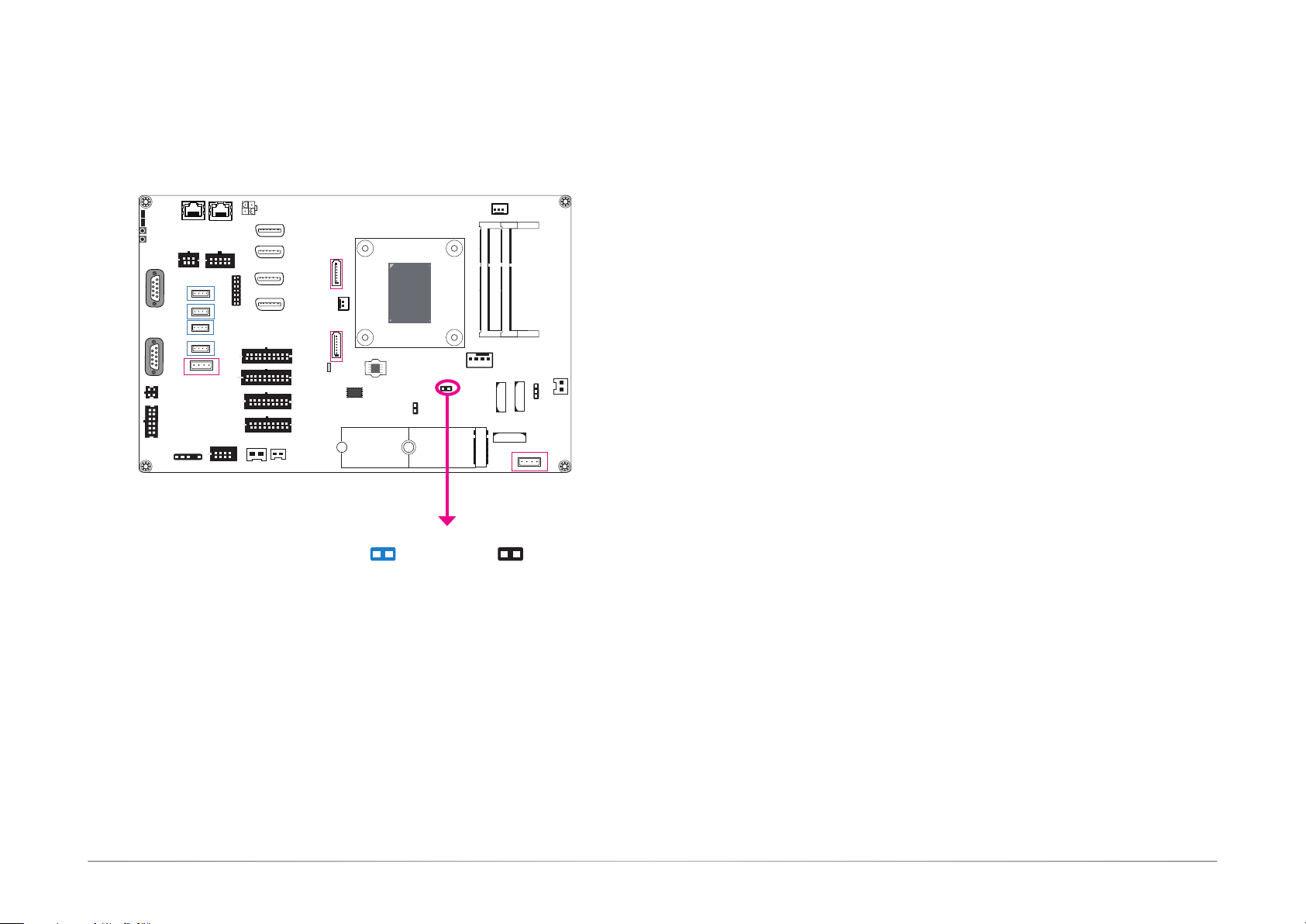
J15 is used to select the MCU programming mode. To enable or disable MCU programming of
the system board, please set the jumper as indicated above.
15User's Manual | GM341-GHF
Page 16
Chapter 5 - Ports and Connectors
Door 1~6
Audio Ports
Chapter 5
System Fan
1
DDR4_2 SODIMM
DDR4_1 SODIMM
1
BAT 2
1
BAT 1
BAT 3
1
USB 3.0_1
Intrusion
Door 8
1
1
Clear COMS (JP1)
4
Power LED
HDD LED
Power Button
Reset Button
COM 2
1
6
5
COM 1
1
6
5
3
1
Speaker
4
2
17
5.1CH
12
6
6
3
COM 3
S/PDIF
LAN 1
4
1
1
USB 2.0_4
1
USB 2.0_3
1
USB 2.0_2
1
USB 2.0_1
1
USB 3.0_2
1
10
5
COM 4/5
4
4
4
4
1
5
Intrusion
LAN 2
4
3
1
L
or
2
4
DC_in
DP 0
6
1
DP 1
1
2
DP 2
LPC
DP 3
20
10
20
10
4
8
18
9
18
9
iButton
DI 1~16
DI 17~32
DO 1~16
DO 17~32
4
Intrusion
Door7
11
11
10
10
1
SATA 3.0
1
SATA 2
1
DC_out
5V/2A
SATA 3.0
1
1
1
1
1
SATA 1
Standby Power LED
SRAM
AMD
TM
Ryzen
V1000Series/
R1000Series
SPI
Flash
MCU Program (J15)
FPGA Program (J12)
1
M.2 2280 (M Key)
Only for the V1000 CPU
CPU Fan
S/PDIF
4-pin Speaker
5.1 Channel Audio
Output
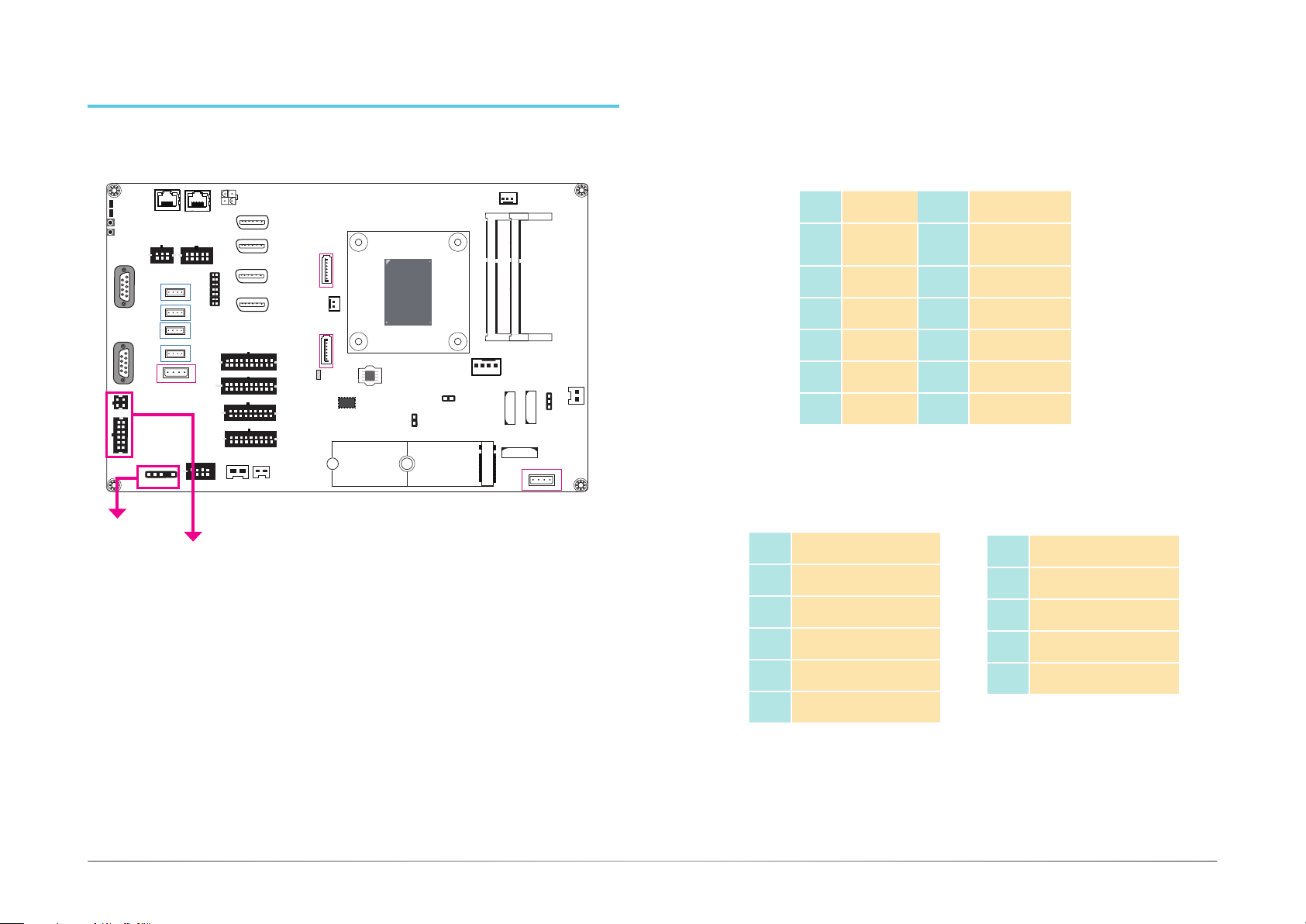
The audio connectors include a 5.1CH audio and a stereo (10W + 10W) speaker output, as
well as the digital audio with the S/PDIF connector. These audio ports are provided by Realtek
RTL8119 Ethernet Controller and ALC888S High Deniton Audio Codec.
• BIOS Setting
Configure the audio controller in the "Advanced" menu ("AMD CHIPSET Setting" > "GFX Configuration" > “NB Azalia”) of the BIOS. Refer to Chapter 7 for more information.
5.1 ch Audio
Pins
1 LINEOUT-L 7 LINEOUT-R
2 GND 8 GND
3 CENOUT-L 9 LFEOUT-R
4 GND 10 GND
5 SIDEOUT-L 11 SIDEOUT-R
6 GND 12 GND
Pin
Assignment
S/PDIF
Pins Pin Assignment
1 +5V
2 Key
3 SPDIF out
4 GND
5 NC
Pins Pin Assignment
4-pin Speaker
Pins Pin Assignment
1 CH-R+
2 CH-L+
3 CH-R-
4 CH-L-
• Driver Installation
You may need to install audio driver in your operating system to use audio devices. Refer to
Chapter 8 and your operating system’s documentation for more information.
16User's Manual | GM341-GHF
Page 17
Chapter 5
USB 3.0_1
Door 1~6
Door7
USB 3.0_1
Door 1~6
Door7
USB Ports
USB 2.0
Power LED
HDD LED
LAN 1
Power Button
Reset Button
6
3
COM 2
COM 3
1
6
5
COM 1
1
6
1
5
3
1
Speaker
4
2
17
5.1CH
12
6
S/PDIF
USB3.0 2
1
4
1
1
USB 2.0_4
1
USB 2.0_3
1
USB 2.0_2
1
USB 2.0_1
USB 3.0_2
1
LAN 2
10
5
COM 4/5
4
4
4
4
4
1
5
Intrusion
DC-in
3
1
L
or
2
4
DC_in
DP 0
6
1
DP 1
1
2
DP 2
LPC
DP 3
20
10
20
10
4
8
18
9
18
9
iButton
DI 1~16
DI 17~32
DO 1~16
DO 17~32
4
Intrusion
11
1
11
1
10
1
10
1
1
SATA 3.0
SATA 2
SATA 3.0
SATA 1
Standby Power LED
1
DC_out
5V/2A
1
1
SRAM
AMD
TM
Ryzen
V1000Series/
R1000Series
SPI
Flash
MCU Program (J15)
FPGA Program (J12)
1
M.2 2280 (M Key)
Only for the V1000 CPU
CPU Fan
4
System Fan
1
DDR4_2 SODIMM
DDR4_1 SODIMM
1
BAT 2
1
BAT 3
BAT 1
1
Intrusion
Door 8
1
1
Clear COMS (JP1)
4
Power LED
HDD LED
Power Button
Reset Button
COM 2
1
6
5
COM 1
1
6
5
3
1
Speaker
4
2
17
5.1CH
12
6
LAN 1
LAN 2
10
4
6
5
1
3
COM 3
COM 4/5
4
1
USB 2.0_4
4
1
USB 2.0_3
4
1
USB 2.0_2
4
1
USB 2.0_1
4
1
USB 3.0_2
3
1
L
or
2
4
1
1
5
Intrusion
S/PDIF
USB3.0 1
3
1
L
or
2
4
DC_in
DP 0
6
1
DP 1
1
2
DP 2
LPC
DP 3
20
10
20
10
18
18
4
8
1
2
DI 1~16
DI 17~32
9
9
DO 17~32
iButton
DO 1~16
3
L
or
4
11
11
10
4
10
1
Intrusion
SATA 3.0
1
SATA 2
1
DC_out
5V/2A
SATA 3.0
1
1
1
1
1
SATA 1
Standby Power LED
SRAM
AMD
TM
Ryzen
V1000Series/
R1000Series
SPI
Flash
MCU Program (J15)
FPGA Program (J12)
1
M.2 2280 (M Key)
Only for the V1000 CPU
CPU Fan
System Fan
1
DDR4_2 SODIMM
DDR4_1 SODIMM
1
BAT 2
1
BAT 3
BAT 1
1
Intrusion
Door 8
1
1
Clear COMS (JP1)
4
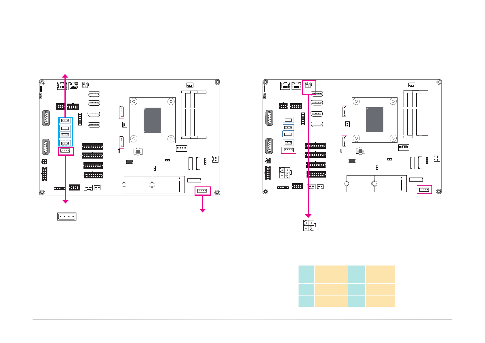
The USB devices allow data exchange between your system and a wide range of simultaneously accessible external Plug and Play peripherals.
The system board is equipped with two USB 3.0 and four USB 2.0 type A vertical ports.
• BIOS Setting
Congure the COM ports including its communication mode in the "Advanced" menu (“USB Configuration” and "SB USB Conguration" under the "CPU" menu) of the BIOS. Refer to Chapter 7
for more information.
The 4-pin vertical DC-in connector provides a low power input solution. Please use a power
adapter with 12V DC output voltage. Using an adapter not compliant to this specification may
fail to boot the system or cause damage to the system board.
Pins
Pin
Assignment
Pins
Pin
Assignment
1 GND 1 3 12V1
2 GND 2 4 12V2
17User's Manual | GM341-GHF
Page 18
Chapter 5
USB 3.0_1
Door 1~6
COM Ports
COM 2: RS232
3
1
L
or
2
Power LED
HDD LED
Power Button
Reset Button
COM 2
1
6
5
COM 1
1
6
5
3
1
4
2
17
12
6
Speaker
5.1CH
6
3
COM 3
S/PDIF
LAN 1
4
1
1
USB 2.0_4
1
USB 2.0_3
1
USB 2.0_2
1
USB 2.0_1
1
USB 3.0_2
1
10
5
COM 4/5
4
4
4
4
1
5
Intrusion
LAN 2
4
4
DC_in
DP 0
6
1
DP 1
1
2
DP 2
LPC
DP 3
20
10
20
10
4
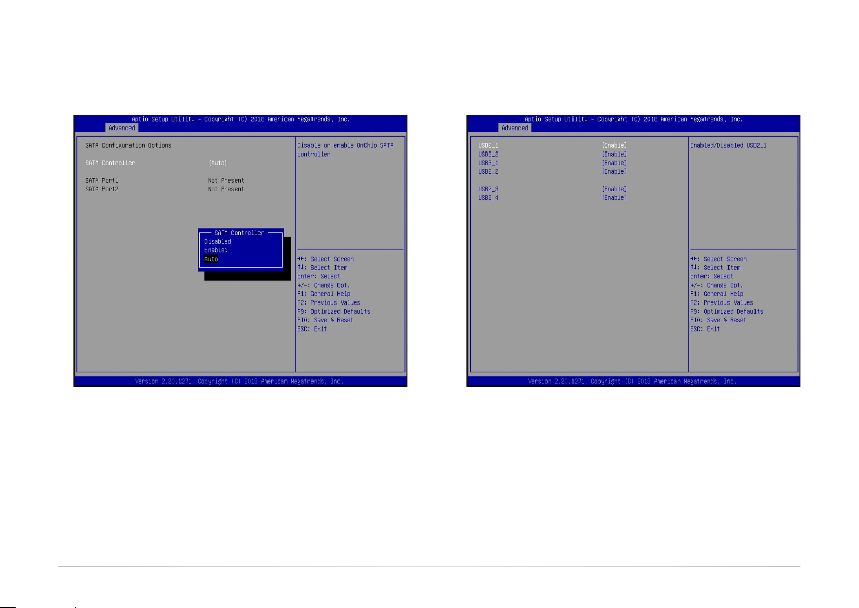
8
18
9
18
9
iButton
DI 1~16
DI 17~32
DO 1~16
DO 17~32
4
1
Intrusion
Door7
11
11
10
10
SATA 3.0
1
SATA 2
1
DC_out
5V/2A
SATA 3.0
1
1
1
1
SATA 1
Standby Power LED
SRAM
1
AMD
TM
Ryzen
V1000Series/
R1000Series
SPI
Flash
MCU Program (J15)
FPGA Program (J12)
1
M.2 2280 (M Key)
Only for the V1000 CPU
CPU Fan
COM 1: RS232/RS422/RS485
COM 3: RS232 (Tx/Rx/GND/ccTalk)
COM 4/5: RS232 (Tx/Rx/+12V/GND)
COM 3
COM 4/5
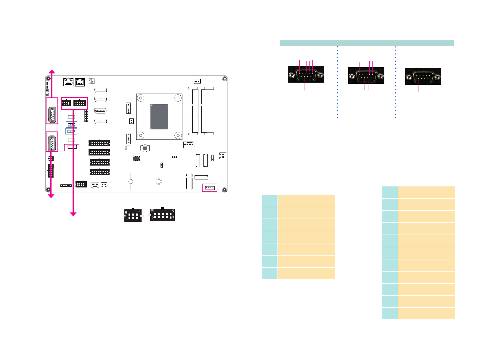
COM 1 and COM 3 can be selected among different communication mode whereas COM 2 can
be used in RS232 mode only. COM 3 and COM 4/5 are pin headers and provide signals that
are different from typical RS232 communication.
Serial Port
The serial port is an asynchronous communication ports that can be used with modems, serial
printers, remote display terminals, and other serial devices. And the ccTalk protocol of COM 3
can be used to connect peripherals used in automatic payment machines for a variety of market
sectors such as transportation, ticketing, gaming and entertainment, and retail. In addition,
through the console redirection function of the BIOS (COM 1 and COM 2), you can monitor and
control the system from a remote station.
• BIOS Setting
Congure the COM ports including its communication mode in the "Advanced" menu (“NCT6116D
Super IO Configuration” submenu) and ("Serial Port Console Redirection" submenu) of the BIOS.
Refer to Chapter 7 for more information.
System Fan
1
DDR4_2 SODIMM
DDR4_1 SODIMM
1
BAT 2
1
BAT 3
BAT 1
1
Intrusion
Door 8
1
1
Clear COMS (JP1)
4
COM 1 (RS232/RS422/RS485) / COM 2 (RS232)
DCD
TXD
RXD
DTR
7
DSR
GND
5
8 9
RI
RTS
CTS
12 3 4
6
RS232
COM 3: RS232
(TX/RX/GND/ccTalk)
Pins Pin Assignment
1 COM3 RS232-TX
2 COM3 RS232-RX
3 GND
4 +12V power out
5 ccTalk
6 GND
TX-
RX+
TX+
RX-
1 2 3 4 5
6 8 9
7
N.C.
N.C.
N.C.
RS422
Full Duplex
GND
DATA-
DATA+
1 2 3 4 5
6 8 9
7
N.C.
N.C.
N.C.
RS485
COM 4/5: RS232
(Tx/Rx/+12V/GND)
Pins Pin Assignment
1 COM4 RS232-TX
2 COM4 RS232-RX
3 +12V power out
4 -12V power out
5 GND
6 COM5 RS232-TX
7 COM5 RS232-RX
8 +12V power out
9 -12V power out
10 GND
N.C.
N.C.
N.C.
GND
N.C.
18User's Manual | GM341-GHF
Page 19
Chapter 5
USB 3.0_1
Door 1~6
System Fan
Door 1~6
RJ45 LAN Ports
LAN 2
LAN 1
Power LED
HDD LED
LAN 1
6
3
COM 3
S/PDIF
4
1
1
USB 2.0_4
1
USB 2.0_3
1
USB 2.0_2
1
USB 2.0_1
1
USB 3.0_2
1
LAN 2
10
5
COM 4/5
4
4
4
4
4
1
5
Intrusion
Power Button
Reset Button
COM 2
1
6
5
COM 1
1
6
5
3
1
Speaker
4
2
17
5.1CH
12
6
Intrusion Doors
3
1
L
or
2
Power LED
HDD LED
LAN 1
Power Button
Reset Button
COM 2
1
6
5
COM 1
1
6
5
3
1
Speaker
4
2
17
5.1CH
12
6
6
3
COM 3
S/PDIF
4
1
1
USB 2.0_4
1
USB 2.0_3
1
USB 2.0_2
1
USB 2.0_1
1
USB 3.0_2
1
10
5
COM 4/5
4
4
4
4
1
5
Intrusion
CPU Fan
1
System Fan
1
DDR4_1 SODIMM
1
BAT 2
DDR4_2 SODIMM
BAT 3
BAT 1
1
Intrusion
Door 8
1
1
Clear COMS (JP1)
4
3
1
L
or
2
4
DC_in
DP 0
6
1
DP 1
1
2
DP 2
LPC
DP 3
20
10
20
10
18
18
4
8
9
9
iButton
DI 1~16
DI 17~32
DO 1~16
DO 17~32
4
1
Intrusion
Door7
11
11
10
1
10
SATA 3.0
1
SATA 2
1
DC_out
5V/2A
SATA 3.0
1
1
1
1
SATA 1
Standby Power LED
SRAM
AMD
TM
Ryzen
V1000Series/
R1000Series
SPI
Flash
MCU Program (J15)
FPGA Program (J12)
1
M.2 2280 (M Key)
Only for the V1000 CPU
Intrusion Door 1~6
LAN 2
4
4
DC_in
DP 0
6
1
DP 1
1
2
DP 2
LPC
DP 3
20
10
20
10
4
8
18
9
18
9
iButton
DI 1~16
DI 17~32
4
DO 1~16
DO 17~32
1
Intrusion
Door7
11
11
10
10
Intrusion Door 7
SATA 3.0
1
1
AMD
TM
Ryzen
V1000Series/
R1000Series
SPI
Flash
MCU Program (J15)
FPGA Program (J12)
1
M.2 2280 (M Key)
Only for the V1000 CPU
Ground
1
Chassis
Signal
CPU Fan
SATA 2
1
DC_out
5V/2A
SATA 3.0
1
SATA 1
1
Standby Power LED
1
1
1
SRAM
Chassis
Signal
Ground
1
DDR4_2 SODIMM
DDR4_1 SODIMM
1
BAT 3
BAT 2
1
BAT 1
1
USB 3.0_1
1
Clear COMS (JP1)
Intrusion Door 8
(for the system board)
Intrusion
4
Door 8
1
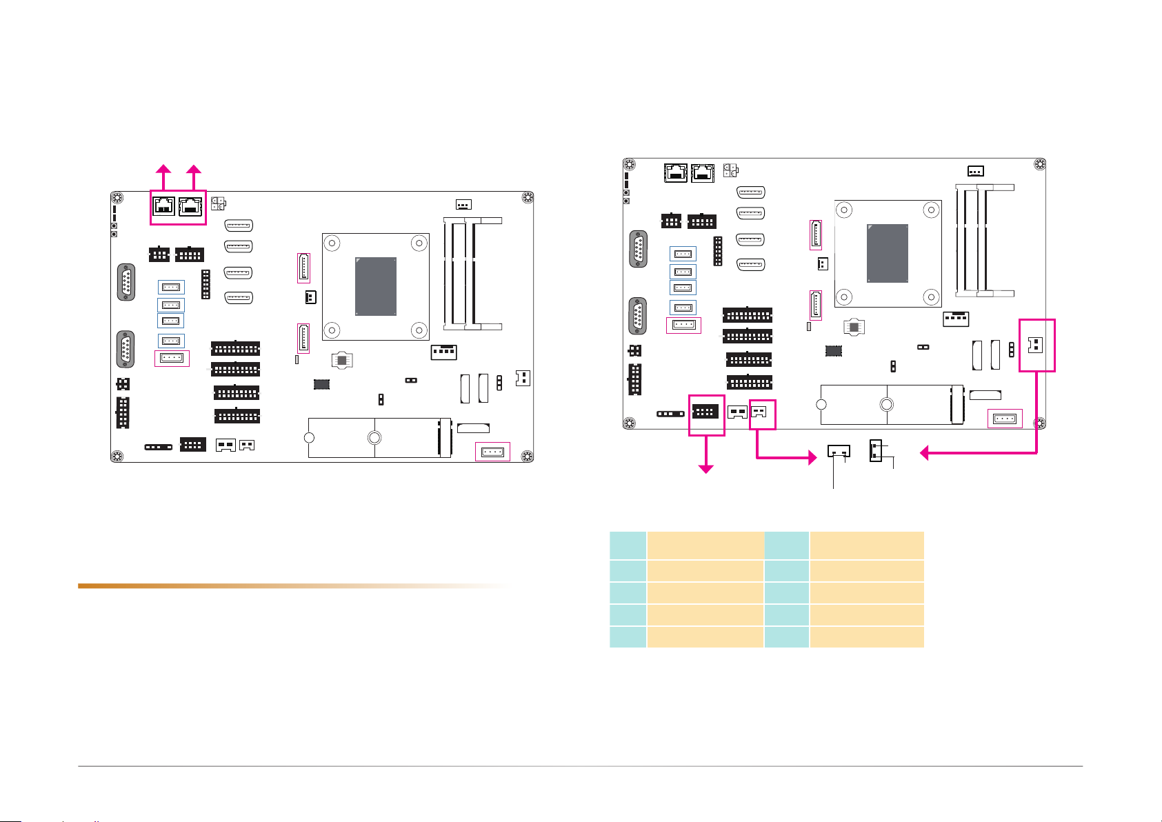
Features
• 2 Realtek® RTL8119 or RTL8111HN Gigabit Ethernet Controller
The LAN ports provide WOL (Wake On LAN) and PXE (Preboot eXecution Environment) functions and these functions can be configured in the BIOS.
BIOS Setting
Configure the onboard LAN in the “Advanced” menu ("ACPI Configuration" and “Network Stack
Conguration” submenus) of the BIOS. Refer to Chapter 7 for more information.
Driver Installation
Install the LAN drivers. Refer to Chapter 8 for more information.
Pins Pin Assignment Pins Pin Assignment
1 Door 1 5 Door 5
2 Door 2 6 Door 6
3 Door 3 7 GND
4 Door 4 8 GND
This intrusion door connector provides 6 pins plus two additional intrusion door connectors for
detecting chassis intrusion events. The demonstration application can display logged events
and the API utility provides logging functions for recording up to a total of 64 entries.
Software
The software package that came with the system contains application and code samples to
implement door intrusion alarms for the system.
19User's Manual | GM341-GHF
Page 20
Chapter 5
System Fan
Door 1~6
USB 3.0_1
Door 1~6
Door7
Display Outputs
Power LED
HDD LED
LAN 1
6
3
COM 3
S/PDIF
4
1
1
USB 2.0_4
1
USB 2.0_3
1
USB 2.0_2
1
USB 2.0_1
1
USB 3.0_2
1
10
5
COM 4/5
4
4
4
4
1
5
Intrusion
LAN 2
4
Power Button
Reset Button
COM 2
1
6
5
COM 1
1
6
5
3
1
4
2
17
12
6
Speaker
5.1CH
1
LPC
1
2
DC_in
6
1
2
20
10
20
10
4
8
3
L
or
4
DP 0
DP 1
DP 2
DP 3
DI 1~16
DI 17~32
18
9
DO 1~16
18
9
DO 17~32
iButton
DP 0~3
4
1
Intrusion
Door7
Digital Inputs/Outputs
CPU Fan
System Fan
1
DDR4_2 SODIMM
DDR4_1 SODIMM
1
BAT 2
1
BAT 3
BAT 1
1
Intrusion
Door 8
1
1
Clear COMS (JP1)
4
3
1
L
or
1
SATA 3.0
1
SATA 2
1
DC_out
5V/2A
SATA 3.0
1
11
SATA 1
1
11
Standby Power LED
1
10
1
10
1
SRAM
AMD
TM
Ryzen
V1000Series/
R1000Series
SPI
Flash
MCU Program (J15)
FPGA Program (J12)
1
M.2 2280 (M Key)
Only for the V1000 CPU
CPU Fan
1
DDR4_2 SODIMM
DDR4_1 SODIMM
1
BAT 2
BAT 3
BAT 1
1
Clear COMS (JP1)
1
USB 3.0_1
Intrusion
4
Door 8
1
Power LED
HDD LED
Power Button
Reset Button
COM 2
1
6
5
COM 1
1
6
5
3
1
Speaker
4
2
17
5.1CH
12
6
6
3
COM 3
S/PDIF
LAN 1
1
USB 2.0_4
1
USB 2.0_3
1
USB 2.0_2
1
USB 2.0_1
1
USB 3.0_2
2
4
DC_in
LAN 2
10
4
5
1
COM 4/5
4
4
4
4
4
1
1
5
Intrusion
DP 0
6
1
DP 1
1
2
DP 2
LPC
DP 3
20
10
DI 1~16
20
10
DI 17~32
18
9
4
DO 1~16
18
9
DO 17~32
iButton
1
Intrusion
4
8
SATA 3.0
1
SATA 2
1
DC_out
5V/2A
SATA 3.0
1
11
SATA 1
1
11
Standby Power LED
1
10
1
10
1
SRAM
AMD
TM
Ryzen
V1000Series/
R1000Series
SPI
Flash
MCU Program (J15)
FPGA Program (J12)
1
M.2 2280 (M Key)
Only for the V1000 CPU
DI 1~16
DI 17~32
DO 1~16
DO 17~32
DI 1~16/17~32
DO 1~16/17~32
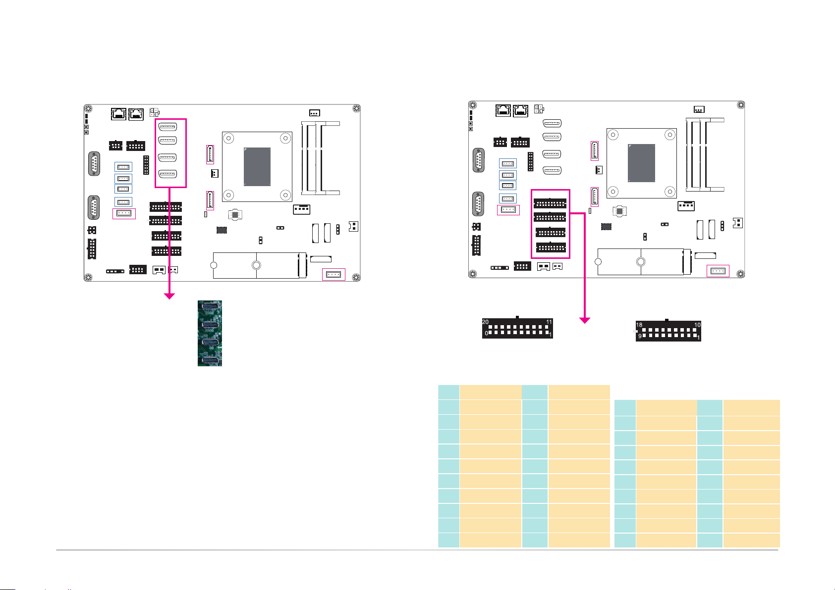
The DisplayPort, a digital display interface, is provided by the integrated AMD® Radeon™
Vega graphics and can be connected to LCD monitors. These ports support resolution up
to 4096x2160. Note that the AMD® Ryzen™ V1000 series processors provide 4 DP++ ports
whereas the R1000 series processors provide 3 DP++ ports.
BIOS Setting
Configure the graphics device in the “Advanced” menu ("AMD CHIPSET Setting" > “GFX Configuration”) of the BIOS. Refer to Chapter 7 for more information.
Driver Installation
Install the AMD
®
Radeon™ graphics driver and software. Please refer to Chapter 8 for more
information.
Digital Input 1~16/17~32
Pins Pin Assignment Pins Pin Assignment
1 DI 1 / DI 17 11 DI 11 / DI 27
2 DI 2 / DI 18 12 DI 12 / DI 28
3 DI 3 / DI 19 13 DI 13 / DI 29
4 DI 4 / DI 20 14 DI 14 / DI 30
5 DI 5 / DI 21 15 DI 15 / DI 31
6 DI 6 / DI 22 16 DI 16 / DI 32
7 DI 7 / DI 23 17 GND
8 DI 8 / DI 24 18 GND
9 DI 9 / DI 25 19 GND
10 DI 10 / DI 26 20 GND
Digital Output 1~16/17~32
Pins Pin Assignment Pins Pin Assignment
1 DO 1 / DO 17 11 DO 10 / DO 26
2 DO 2 /DO 18 12 DO 11 / DO 27
3 DO 3 / DO 19 13 DO 12 / DO 28
4 DO 4 / DO 20 14 DO 13 / DO 29
5 DO 5 / DO 21 15 DO 14 / DO 30
6 DO 6 / DO 22 16 DO 15 / DO 31
7 DO 7 / DO 23 17 DO 16 / DO 32
8 DO 8 / DO 24 18 GND
9 DO 9 / DO 25 19 GND
20User's Manual | GM341-GHF
Page 21

The Digital I/O connector provides 32-bit digital inputs or outputs to enable monitor and
control of the states of the connected external devices. The recommended application voltage
range is from 0 V to 24 V.
The digital I/O ports support Electrostatic discharge (ESD) protection to prevent damage from
ESD strikes between two connected devices. The following are detailed features:
• Protects one data or I/O line
• Max. peak pulse power: 160W at tp = 8/20 us.
• Low clamping voltage
• IEC 61000-4-2, level 4 (ESD), >+ 15KV (air); >+ 8KV (contact)
Software
The system comes with a demonstration program and an API utility, allowing you to control
digital I/O pins. The GPIO Control API of the GamingLogic API utility allows you to control
the digital input/output pins. Please contact your sales representative for the gaming software
package.
Driver Installation
Install the Windows WinDriver. Please refer to Chapter 8 for more information.
Chapter 5
21User's Manual | GM341-GHF
Page 22
Chapter 5
USB 3.0_1
Door 1~6
Door7
System Fan
USB 3.0_1
Door 1~6
Door7
Expansion Connectors
3
1
L
or
2
Power LED
HDD LED
Power Button
Reset Button
COM 2
1
6
5
COM 1
1
6
5
3
1
Speaker
4
2
17
5.1CH
12
6
6
3
COM 3
S/PDIF
LAN 1
4
1
1
USB 2.0_4
1
USB 2.0_3
1
USB 2.0_2
1
USB 2.0_1
1
USB 3.0_2
10
5
COM 4/5
1
LAN 2
4
4
4
4
4
1
5
Intrusion
4
DC_in
DP 0
6
1
DP 1
1
2
DP 2
LPC
DP 3
20
10
DI 1~16
20
10
DI 17~32
18
9
4
DO 1~16
18
9
DO 17~32
4
8
Intrusion
iButton
CPU/System Fan Connector
Power
1
SPI
Flash
FPGA Program (J12)
Sense
AMD
Ryzen
V1000Series/
R1000Series
1
M.2 2280 (M Key)
Only for the V1000 CPU
3
TM
CPU Fan
MCU Program (J15)
1
DDR4_2 SODIMM
DDR4_1 SODIMM
1
BAT 2
1
BAT 3
BAT 1
1
CTRL
RPM
Intrusion
Door 8
1
1
Clear COMS (JP1)
4
Ground
12V
Ground
M.2 Type 2280 (PCIe 3.0 x2)
3
1
L
or
2
Power LED
HDD LED
System Fan
1
SATA 3.0
1
SATA 2
1
DC_out
5V/2A
SATA 3.0
1
11
SATA 1
1
11
Standby Power LED
1
10
1
10
1
1
SRAM
AMD
TM
Ryzen
V1000Series/
R1000Series
SPI
Flash
MCU Program (J15)
FPGA Program (J12)
1
M.2 2280 (M Key)
Only for the V1000 CPU
CPU Fan
1
DDR4_2 SODIMM
DDR4_1 SODIMM
1
BAT 2
BAT 3
BAT 1
1
Intrusion
Door 8
1
Clear COMS (JP1)
4
1
Power Button
Reset Button
COM 2
1
6
5
COM 1
1
6
5
3
1
4
2
17
12
6
Speaker
5.1CH
6
3
S/PDIF
LAN 1
COM 3
4
1
1
USB 2.0_4
1
USB 2.0_3
1
USB 2.0_2
1
USB 2.0_1
1
USB 3.0_2
1
10
5
COM 4/5
LAN 2
4
4
4
4
4
1
5
Intrusion
4
DC_in
DP 0
6
1
DP 1
1
2
DP 2
LPC
DP 3
20
10
DI 1~16
20
10
DI 17~32
18
9
4
DO 1~16
18
9
DO 17~32
iButton
1
Intrusion
4
8
SATA 3.0
1
SATA 2
1
DC_out
5V/2A
SATA 3.0
1
11
SATA 1
1
11
Standby Power LED
1
10
1
10
1
SRAM
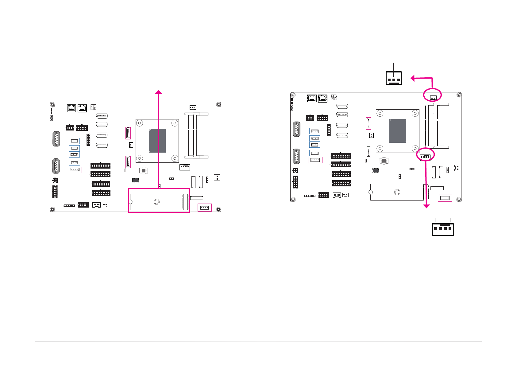
M.2 M Key slot (only with the AMD® Ryzen™ V1000 series processors)
The M.2 type 2280 card slot (M Key) supports PCIe NVMe 3.0 x2 interface to accommodate
NVMe SSDs. It can be inserted with an M.2 (NGFF) card with the form factor of 22x80 mm.
4
1
The fan connector is used to connect cooling fan. The cooling fan will provide adequate airflow
throughout the chassis to prevent overheating the CPU and system board components.
BIOS Setting
The Advanced menu (“
NCT6116D HW Monitor
” submenu) of the BIOS will display the current
speed of the cooling fans. Refer to the Chapter 7 for more information.
22User's Manual | GM341-GHF
Page 23
Chapter 5
System Fan
Door 1~6
USB 3.0_1
Door 1~6
Door7
LEDs
Power LED
HDD LED
Power LED
HDD LED
Power Button
Reset Button
COM 2
1
6
5
COM 1
1
6
5
3
1
4
2
17
12
6
Speaker
5.1CH
6
3
COM 3
S/PDIF
LAN 1
4
1
1
USB 2.0_4
1
USB 2.0_3
1
USB 2.0_2
1
USB 2.0_1
1
USB 3.0_2
1
10
5
COM 4/5
4
4
4
4
1
5
Intrusion
LAN 2
4
Battery
3
1
L
or
2
Power LED
HDD LED
LAN 1
Power Button
Reset Button
COM 2
1
6
5
COM 1
1
6
5
3
1
Speaker
4
2
17
12
6
5.1CH
6
3
COM 3
S/PDIF
4
1
1
USB 2.0_4
1
USB 2.0_3
1
USB 2.0_2
1
USB 2.0_1
1
USB 3.0_2
1
10
CPU Fan
System Fan
1
DDR4_2 SODIMM
DDR4_1 SODIMM
1
BAT 2
1
BAT 3
BAT 1
1
Intrusion
Door 8
1
Clear COMS (JP1)
4
1
3
1
L
or
2
4
DC_in
DP 0
6
1
DP 1
1
2
DP 2
LPC
DP 3
20
10
DI 1~16
20
10
DI 17~32
18
9
4
DO 1~16
18
9
DO 17~32
iButton
1
Intrusion
4
8
SATA 3.0
1
SATA 2
1
DC_out
5V/2A
SATA 3.0
1
11
SATA 1
1
11
Standby Power LED
1
10
1
10
1
SRAM
AMD
TM
Ryzen
V1000Series/
R1000Series
SPI
Flash
MCU Program (J15)
FPGA Program (J12)
1
M.2 2280 (M Key)
Only for the V1000 CPU
LAN 2
5
COM 4/5
4
4
4
4
4
1
5
Intrusion
4
DC_in
DP 0
6
1
DP 1
1
2
DP 2
LPC
DP 3
20
10
DI 1~16
20
10
DI 17~32
18
9
4
DO 1~16
18
9
DO 17~32
iButton
1
Intrusion
Door7
4
8
SATA 3.0
1
SATA 2
1
DC_out
5V/2A
SATA 3.0
1
11
SATA 1
1
11
Standby Power LED
1
10
1
10
1
SRAM
AMD
TM
Ryzen
V1000Series/
R1000Series
SPI
Flash
MCU Program (J15)
FPGA Program (J12)
1
M.2 2280 (M Key)
Only for the V1000 CPU
CPU Fan
Battery 2 & Battery 3: SRAMs
Battery 1: System & MCU
Battery
Standby LED
GND
1
DDR4_2 SODIMM
DDR4_1 SODIMM
1
BAT 2
1
BAT 1
BAT 3
1
USB 3.0_1
Intrusion
Door 8
1
1
Clear COMS (JP1)
4
1
2
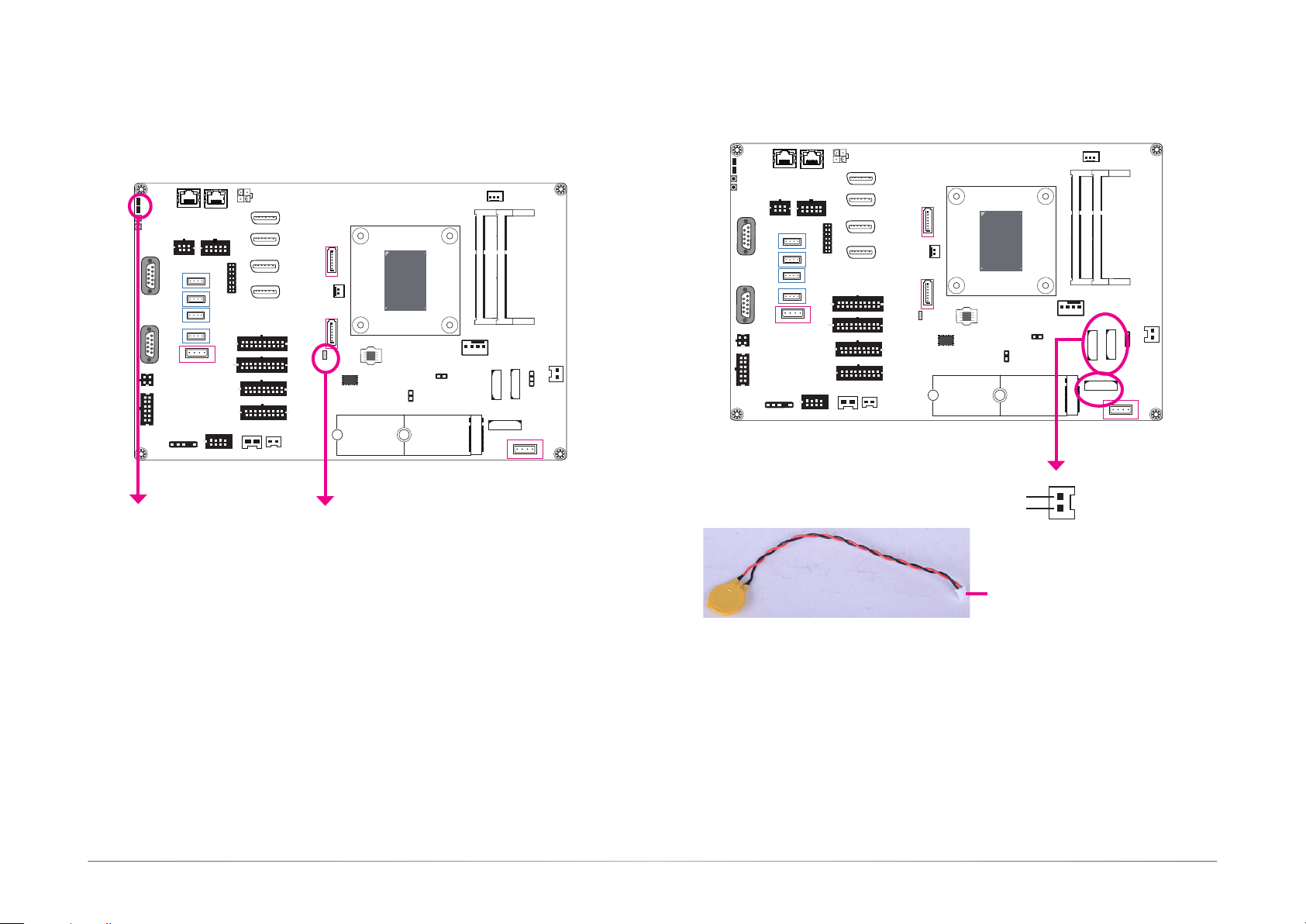
Power LED (green)
This LED will be green when the system is powered on.
HDD LED (flashing orange)
The HDD LED will flash orange when storage devices are being accessed.
Standby LED
This LED will be red when there is power on the system board.
Battery
Connect to the battery connector
The lithium-ion battery is an auxiliary source of power when the main power is shut off. Two
of them provide power for the Static Random-Access Memories (BAT 2 & 3) and one provides
power for the MCU and the system's CMOS memory (BAT 1). The batteries for SRAM enables
the system to retain data for 5 years without AC power supply. The demonstration application
can show the voltage readings as well as set threshold values and its API utility provides functions for battery voltage monitoring.
Safety Measures
• Danger of explosion if battery is incorrectly replaced.
• Replace only with the same or equivalent type recommend by the manufacturer.
• Dispose of used batteries according to local ordinance.
Software
The software package that came with the system contains application and code samples to
implement voltage monitoring and alarms for the system.
23User's Manual | GM341-GHF
Page 24
Chapter 5
USB 3.0_1
Door 1~6
Door7
System Fan
USB 3.0_1
Door 1~6
SATA (Serial ATA) Connectors
3
1
L
or
2
Power LED
HDD LED
Power Button
Reset Button
COM 2
1
6
5
COM 1
1
6
5
3
1
Speaker
4
2
17
12
6
5.1CH
6
3
COM 3
S/PDIF
LAN 1
4
1
1
USB 2.0_4
1
USB 2.0_3
1
USB 2.0_2
1
USB 2.0_1
1
USB 3.0_2
10
5
COM 4/5
1
LAN 2
4
4
4
4
4
1
5
Intrusion
4
DC_in
DP 0
6
1
DP 1
1
2
DP 2
LPC
DP 3
20
10
DI 1~16
20
10
DI 17~32
18
9
4
DO 1~16
18
9
DO 17~32
iButton
1
Intrusion
4
8
11
1
11
1
10
1
10
1
SATA 2
SATA 1
SATA 3.0
SATA 2
SATA 3.0
SATA 1
Standby Power LED
1
DC_out
5V/2A
1
1
SRAM
SATA 3.0 6Gb/s
AMD
Ryzen
V1000Series/
R1000Series
SPI
Flash
FPGA Program (J12)
1
1
GND
TXP
TXN
GND
RXN
RXP
+5V / GND
7
TM
CPU Fan
MCU Program (J15)
1
M.2 2280 (M Key)
Only for the V1000 CPU
System Fan
1
DDR4_1 SODIMM
1
BAT 2
DDR4_2 SODIMM
BAT 3
BAT 1
1
Clear COMS (JP1)
1
Intrusion
4
Door 8
LPC Connector
3
1
L
or
2
Power LED
HDD LED
LAN 1
Power Button
Reset Button
COM 2
6
5
COM 1
1
6
5
1
3
1
4
2
17
12
6
1
Speaker
5.1CH
6
3
COM 3
S/PDIF
4
1
1
USB 2.0_4
1
USB 2.0_3
1
USB 2.0_2
1
USB 2.0_1
1
USB 3.0_2
1
10
5
COM 4/5
LAN 2
4
4
4
4
4
1
5
Intrusion
LPC
4
DC_in
DP 0
6
1
DP 1
1
2
DP 2
LPC
DP 3
20
10
DI 1~16
20
10
DI 17~32
18
9
4
DO 1~16
18
9
DO 17~32
iButton
1
Intrusion
Door7
4
8
1
SATA 3.0
1
SATA 2
1
DC_out
5V/2A
SATA 3.0
1
11
SATA 1
1
11
Standby Power LED
1
10
1
10
1
SRAM
AMD
TM
Ryzen
V1000Series/
R1000Series
SPI
Flash
MCU Program (J15)
FPGA Program (J12)
1
M.2 2280 (M Key)
Only for the V1000 CPU
CPU Fan
2
13 14
1
DDR4_2 SODIMM
DDR4_1 SODIMM
1
BAT 2
1
BAT 3
BAT 1
1
Intrusion
Door 8
1
Clear COMS (JP1)
4
1
Features
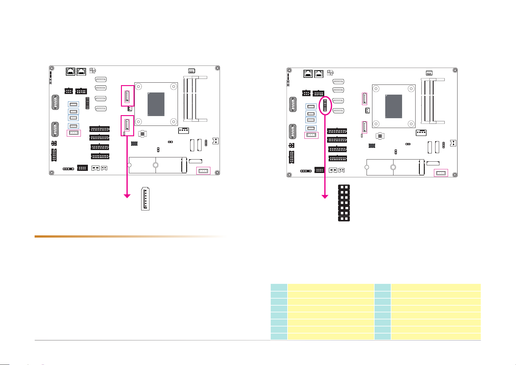
• 2 Serial ATA 3.0 ports
- SATA port 1 and 2 with data transfer rate up to 6Gb/s
• Pin 7 provides +5V power and can switch between +5V and GND automatically
The Serial ATA connectors are used to connect the Serial ATA devices such as a Serial ATA
Disk on Module (SATA DOM).
BIOS Setting
Configure the Serial ATA drives in the Advanced menu ("AMD CHIPSET Setting" > “SATA Configuration Options”) of the BIOS. Refer to Chapter 7 for more information.
The Low Pin Count Interface was dened by Intel® Corporation to facilitate the industry’s transi-
tion towards legacy free systems. It allows the integration of low-bandwidth legacy I/O components within the system, which are typically provided by a Super I/O controller. Furthermore, it
can be used to interface rmware hubs, Trusted Platform Module (TPM) devices and embedded
controllers. Data transfer on the LPC bus is implemented over a 4 bit serialized data interface,
which uses a 24MHz LPC bus clock. For more information about LPC bus, please refer to the
Intel® Low Pin Count Interface Specication Revision 1.1’. The table below indicates the pin
functions of the LPC connector.
Pin Pin Assignment Pin Pin Assignment
11
13
1
3
5
7
9
L_CLK
L_RST#
L_FRAME#
L_AD3
L_AD2
INT_SERIRQ
5VSB
2
4
6
8
10
12
14
L_AD1
L_AD0
3V3
GND
Key
GND
5V
24User's Manual | GM341-GHF
Page 25
USB 3.0_1
Door 1~6
Door7
5V DC-out
Chapter 5
Power LED
HDD LED
Power Button
Reset Button
COM 2
1
6
5
COM 1
1
6
5
3
1
Speaker
4
2
17
5.1CH
12
6
6
3
COM 3
S/PDIF
LAN 1
4
1
1
USB 2.0_4
1
USB 2.0_3
1
USB 2.0_2
1
USB 2.0_1
1
USB 3.0_2
1
LAN 2
10
5
COM 4/5
4
4
4
4
4
1
5
Intrusion
LPC
1
2
6
1
1
4
8
10
10
DC_in
2
20
20
18
9
18
9
iButton
3
L
or
4
DI 1~16
DI 17~32
DO 1~16
DO 17~32
DP 0
DP 1
DP 2
DP 3
11
1
11
1
10
1
4
10
1
1
Intrusion
+5V DC
power_out
SATA 3.0
SATA 2
SATA 3.0
SATA 1
Standby Power LED
1
DC_out
5V/2A
1
2
1
1
SRAM
AMD
Ryzen
V1000Series/
R1000Series
SPI
Flash
FPGA Program (J12)
1
GND
TM
CPU Fan
MCU Program (J15)
1
M.2 2280 (M Key)
Only for the V1000 CPU
System Fan
1
DDR4_1 SODIMM
1
BAT 2
DDR4_2 SODIMM
BAT 3
BAT 1
1
Clear COMS (JP1)
1
Intrusion
4
Door 8
1
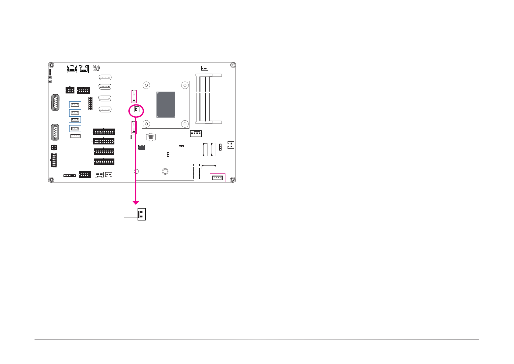
The 2-pin connector provides low power output of 5V/2A.
25User's Manual | GM341-GHF
Page 26
Chapter 6 - Mounting
Note:
The system unit used in the following illustrations may not resemble the actual one.
These illustrations are for reference only.
Wall Mount
Chapter 6
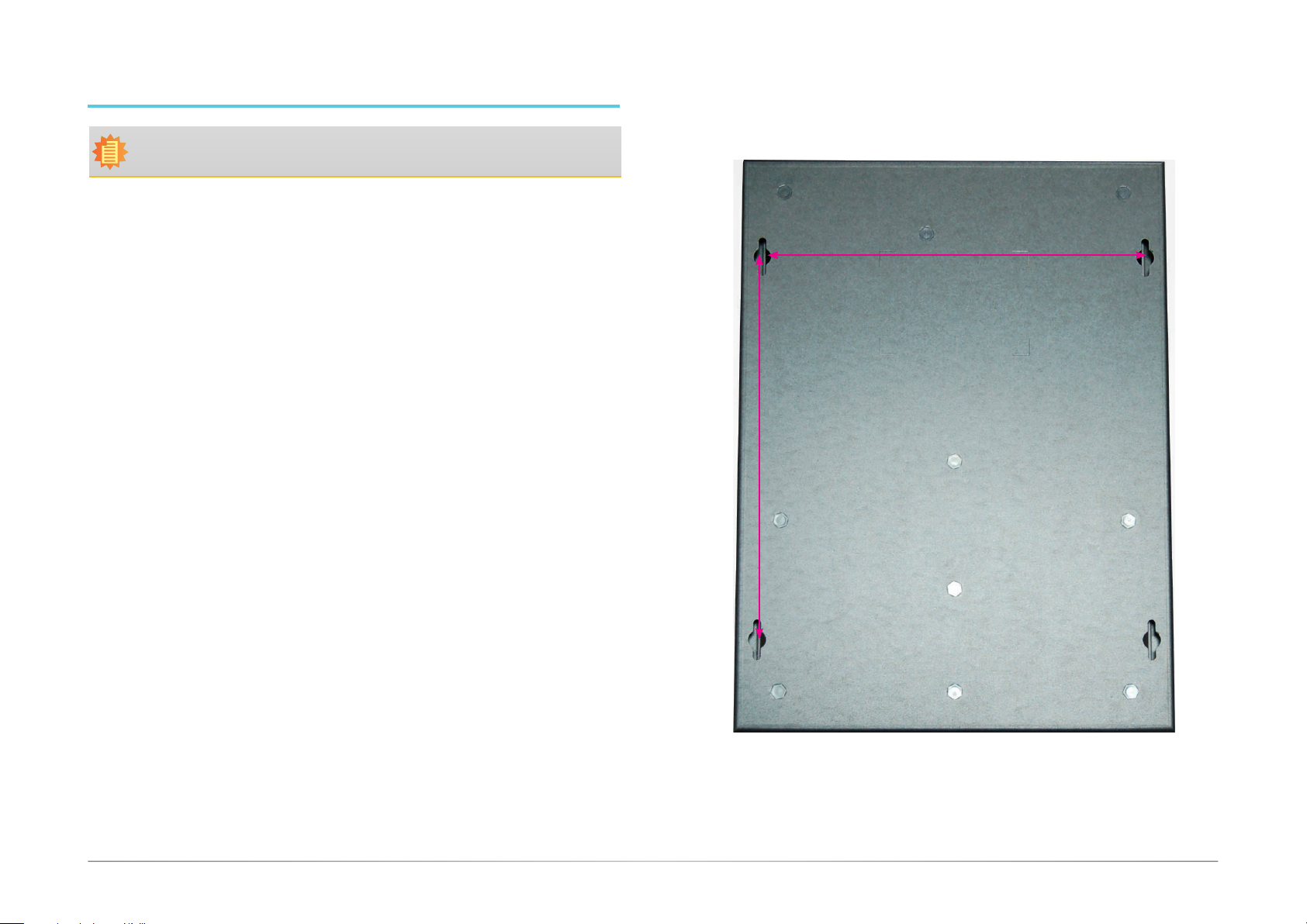
The system has screw holes on the bottom of the chassis to support wall mount.
1. Drill 4 holes in the wall and insert screw bolts into the holes.
2. Drill the screws into the screw anchors.
3. Hang the device on the wall.
The diagram on the right shows the screw holes and dimensions of wall mount (in millimeter).
Screw hole
(Diameter: 8.2)
Screw hole
180
180
Screw hole
Screw hole
26User's Manual | GM341-GHF
Page 27
Chapter 7 - BIOS Setup
Overview
The BIOS is a program that takes care of the basic level of communication between the CPU
and peripherals. It contains codes for various advanced features found in this system board.
The BIOS allows you to configure the system and save the configuration in a battery-backed
CMOS so that the data retains even when the power is off. In general, the information stored
in the CMOS RAM of the EEPROM will stay unchanged unless a configuration change has been
made such as a hard drive replaced or a device added.
It is possible that the CMOS battery will fail causing CMOS data loss. If this happens, you need
to install a new CMOS battery and reconfigure the BIOS settings.
Note:
The BIOS is constantly updated to improve the performance of the system board;
therefore the BIOS screens in this chapter may not appear the same as the actual
one. These screens are for reference purpose only.
Default Configuration
Most of the configuration settings are either predefined according to the Load Optimal Defaults
settings which are stored in the BIOS or are automatically detected and configured without requiring any actions. There are a few settings that you may need to change depending on your
system configuration.
Entering the BIOS Setup Utility
The BIOS Setup Utility can only be operated from the keyboard and all commands are keyboard commands. The commands are available at the right side of each setup screen.
The BIOS Setup Utility does not require an operating system to run. After you power up the
system, the BIOS message appears on the screen and the memory count begins. After the
memory test, the message “Press DEL to run setup” will appear on the screen. If the message
disappears before you respond, restart the system or press the “Reset” button. You may also
restart the system by pressing the <Ctrl> <Alt> and <Del> keys simultaneously.
Chapter 7
Legends
Keys Function
Right and Left arrows
Up and Down arrows
<Esc>
+ (plus key)
- (minus key)
<F1>
<F2>
<F9>
<F10>
<Enter>
Scrolls forward through the values or options of the highlighted eld.
Scrolls backward through the values or options of the highlighted eld.
Scroll Bar
When a scroll bar appears to the right of the setup screen, it indicates that there are more
available fields not shown on the screen. Use the up and down arrow keys to scroll through all
the available fields.
Submenu
When ““ appears on the left of a particular field, it indicates that a submenu which contains
additional options are available for that field. To display the submenu, move the highlight to
that field and press <Enter>.
Moves the highlight left or right to select a menu.
Moves the hightlight up or down between submenu or elds.
Exit to the BIOS Setup Utility.
Displays general help
Pervious values
Optimized defaults
Saves and resets the setup program.
Press <Enter> to enter the highlighted submenu.
27User's Manual | GM341-GHF
Page 28
AMI BIOS Setup Utility Advanced
Chapter 7
Main
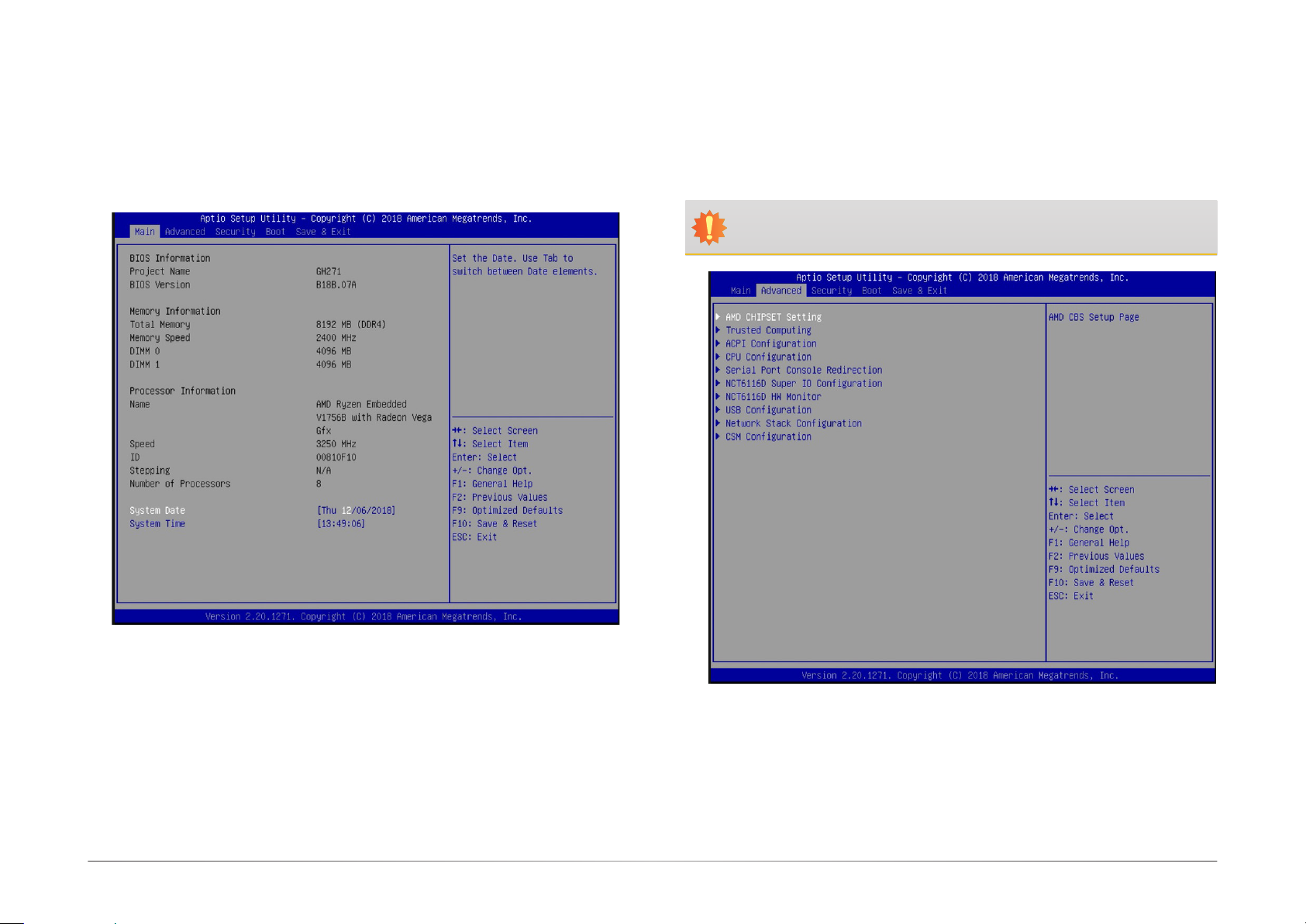
The Main menu is the first screen that you will see when you enter the BIOS Setup Utility.
The Advanced menu allows you to configure your system for basic operation. Some entries are
defaults required by the system board, while others, if enabled, will improve the performance
of your system or let you set some features according to your preference.
Important:
Setting incorrect field values may cause the system to malfunction.
System Date
The date format is <day>, <month>, <date>, <year>. Day displays a day, from Sunday
to Saturday. Month displays the month, from January to December. Date displays the date,
from 1 to 31. Year displays the year, from 1980 to 2099.
System Time
The time format is <hour>, <minute>, <second>. The time is based on the 24-hour
military-time clock. For example, 1 p.m. is 13:00:00. Hour displays hours from 00 to 23.
Minute displays minutes from 00 to 59. Second displays seconds from 00 to 59.
28User's Manual | GM341-GHF
Page 29
Chapter 7
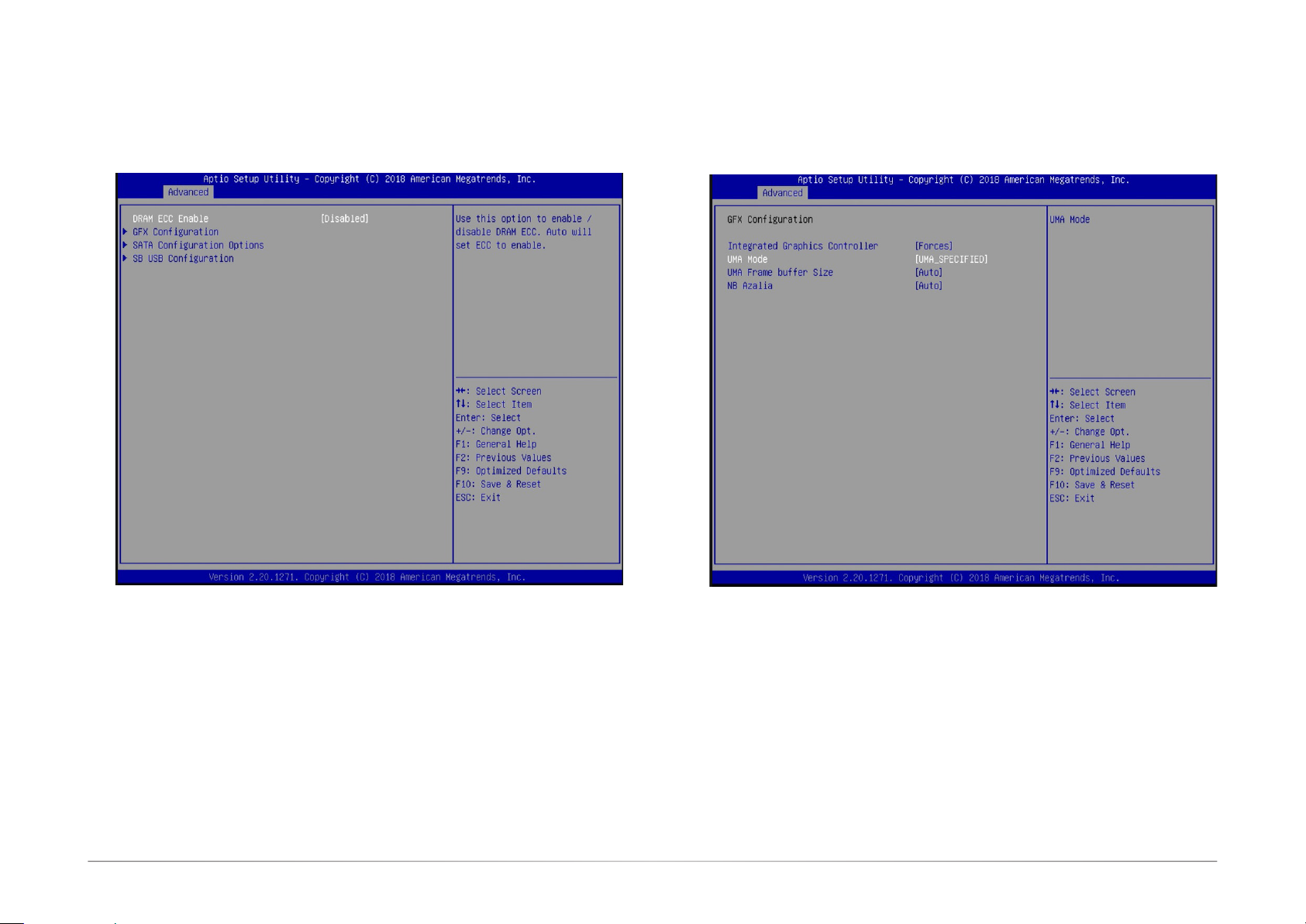
AMD CHIPSET Setting
This section configures the parameters of the AMD chipset.
GFX Configuration
This section configures the parameters of the integrated graphics.
DRAM ECC Enable
Enable or disable the support for ECC memory.
Integrated Graphics Controller
Configure the integrated graphics controller with these options: Disabled, Forces, or Auto.
UMA Mode
This option only appears if the Integrated Graphics Controller is set to Forces. Select the
UMA (Unified Memory Architecture) mode from these options: Auto or UMA_SPECIFIED.
UMA Frame buffer Size
This option only appears if you choose to specify the UMA mode. Congure the UMA frame
buffer size with these options: Auto, 64M, 128M, 256M, 384M, 512M, 1G, or 2G.
NB Azalia
Automatically congure the integrated high-denition audio controller or disable it.
29User's Manual | GM341-GHF
Page 30
Chapter 7
SATA Configuration Options
This section configures the parameters of the SATA controller.
SB USB Configuration
This section configures the parameters of the USB controller.
SATA Controller
Enable, disable or automatically configure the SATA controller.
SATA Port 1
Enable or disable each SATA port.
USB2_1 USB2_2 USB2_3 USB2_4
Enable or disable each USB 2.0 port.
USB3_1 USB3_2
Enable or disable each USB 3.0 port.
30User's Manual | GM341-GHF
Page 31
Chapter 7
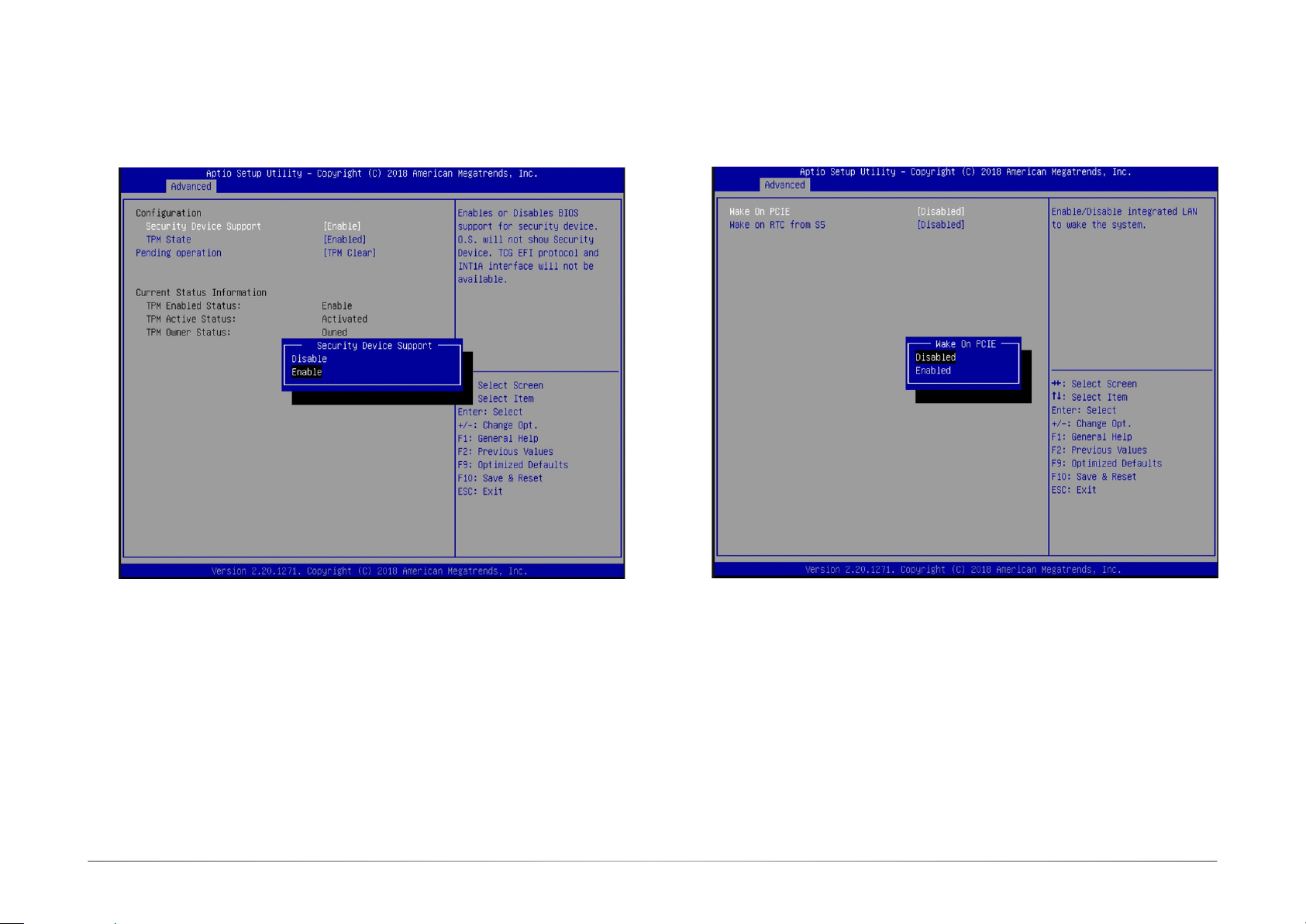
Trusted Computing
This section configures security settings.
ACPI Configuration
This section configures system ACPI parameters.
Security Device Support
Enable or disable the support for Trusted Platform Module (TPM) and allow the BIOS to
automatically download the drivers needed to activate this function. After you have enabled
this function, you can change the TPM state which allows different TPM operations.
TPM State
Enable or disable the TPM State.
Pending Operation
Schedule an operation for the security device.
Wake on PCIE
Enable or disable automatic system wake-up using the integrated LAN.
Wake on RTC from S5
Enable or disable the resume on RTC alarm function, which automatically powers on the
system from S5 power state (soft-off state) at the specified time every day.
Wake up hour Input any value between 0 and 23.
Wake up minute Input any value between 0 and 59.
Wake up second Input any value between 0 and 59.
31User's Manual | GM341-GHF
Page 32
Chapter 7
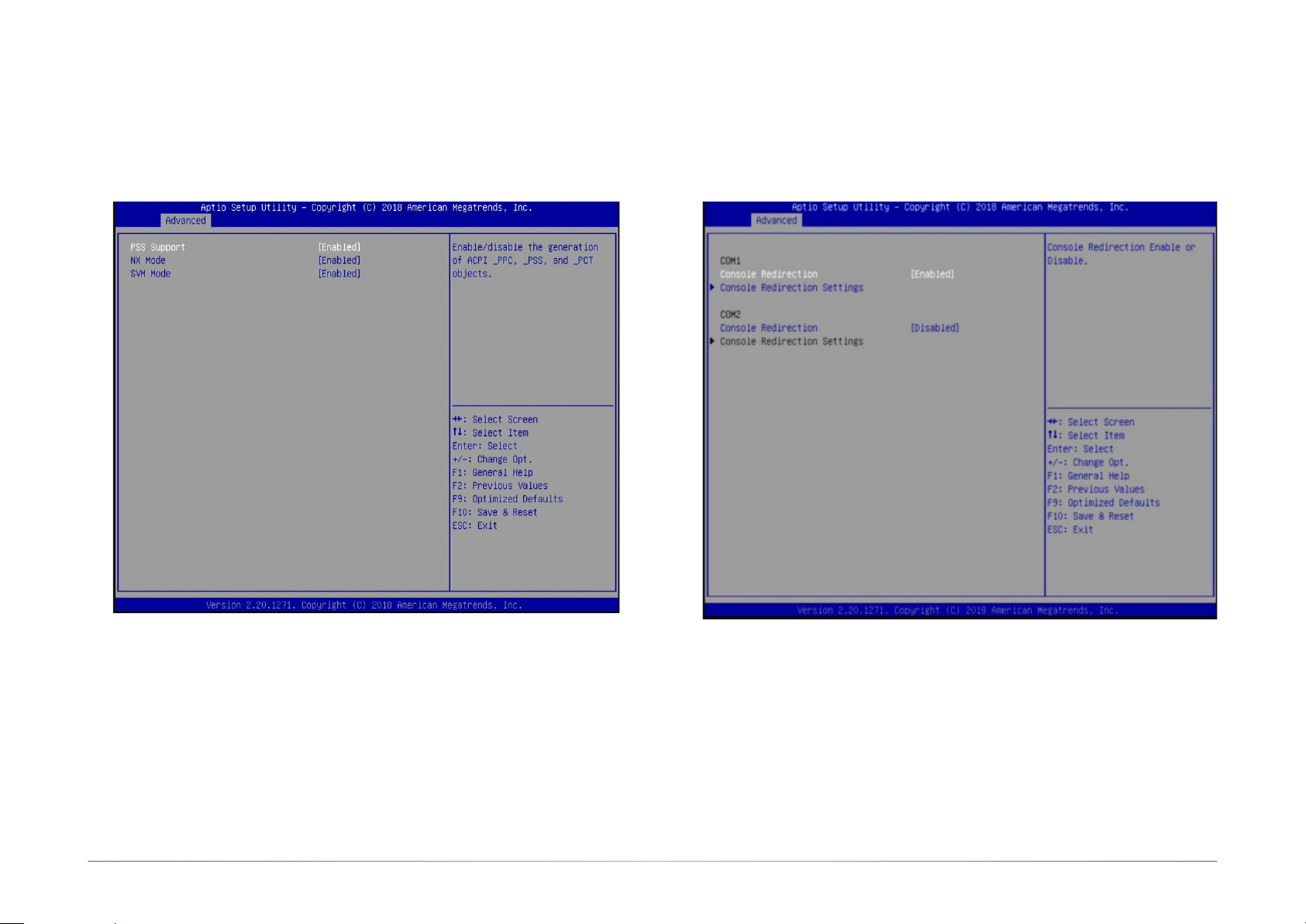
CPU Configuration
This section configures the CPU.
Serial Port Console Redirection
Console redirection lets you monitor and control the system from a remote station by re-directing the host screen output through a serial port.
PSS Support
Enable or disable the generation of ACPI PPC, PSS, and PCT objects. These objects are
associated with the operation of CPU P-state.
NX Mode
Enable or disable the non-execute page protection function.
SVM Mode
Enable or disable the CPU virtualization function.
32User's Manual | GM341-GHF
Page 33
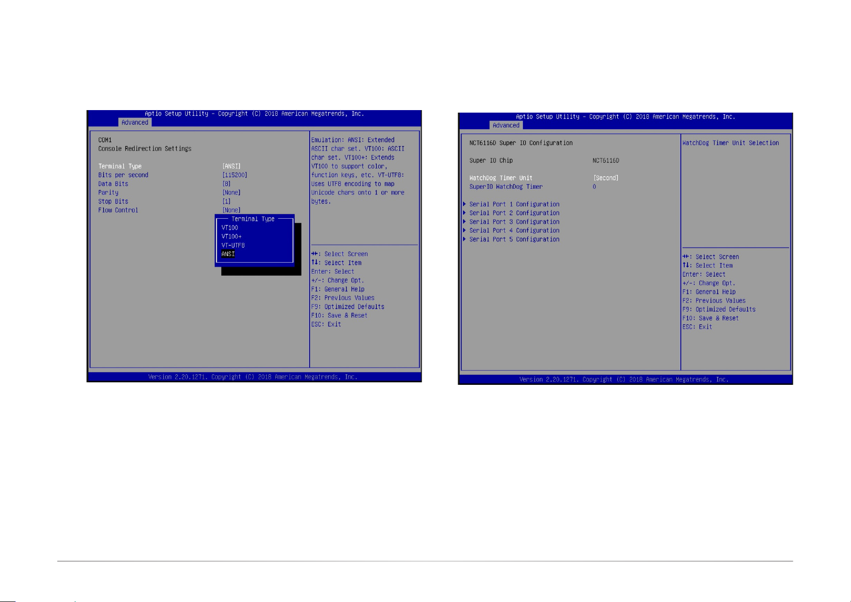
NCT6116D Super IO Configuration
This section configures the system super I/O chip parameters.
Chapter 7
Console Redirection Settings
Enable or disable the console redirection function. (The default is disabled.) If you select
to enable it, please configure the following parameters for serial communication between
the system and a remote station:
Terminal type: VT100, VT100+, VT-UTF8, or ANSI.
Bits per second: 115200, 57600, 38400, 19200 or 9600.
Data bits: 8 bits or 7 bits.
Parity: None, Even or Odd.
Stop bits: 1 bit or 2 bits.
Flow control: None or Hardware RTS/CTS.
WatchDog Timer Unit
SuperIO WatchDog Timer
Enable or disable the watchdog function. A counter will appear if you select to enable
the WDT. Input any value between 1 to 255 in the “SuperIO WatchDog Timer” field.
33User's Manual | GM341-GHF
Page 34
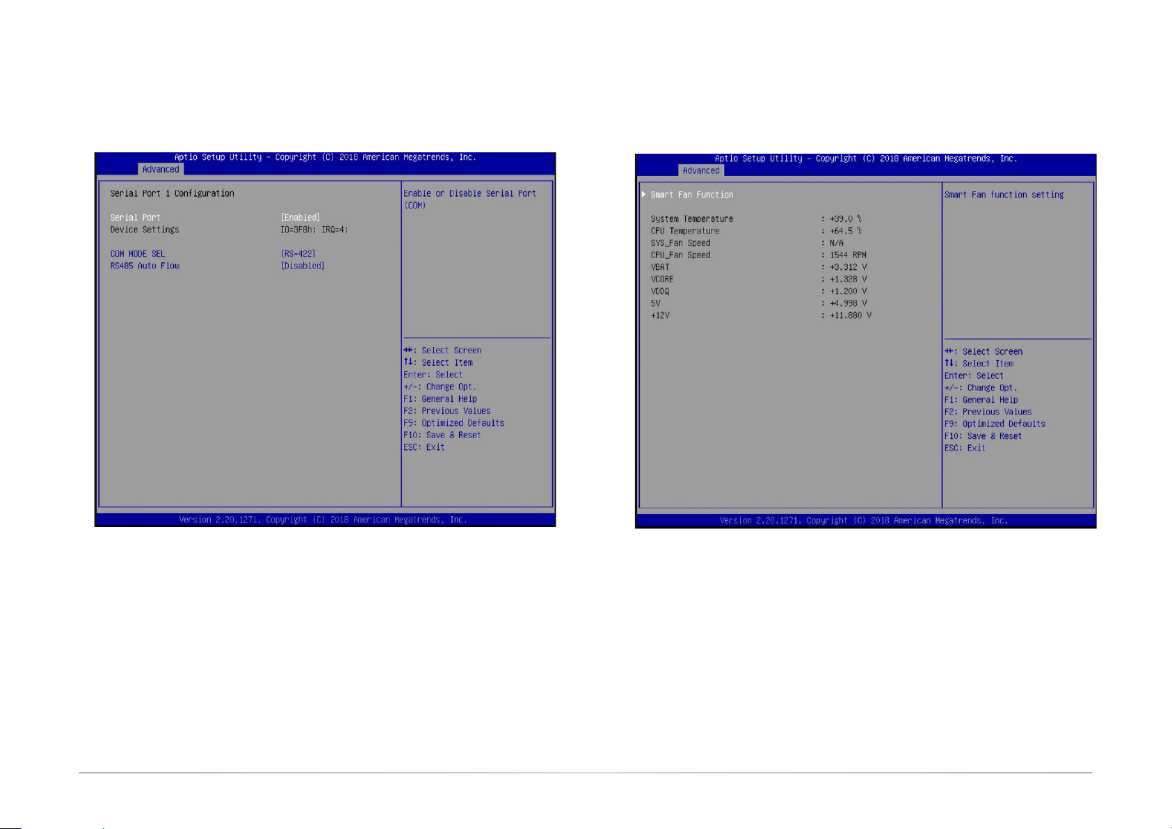
NCT6116D HW Monitor
This section displays the hardware health status.
Chapter 7
Serial Port 1 to 5
Enable or disable the serial port (COM).
Device Settings
It shows the IO/IRQ settings for the super I/O device.
COM MODE SEL (only available for Serial Port 1 and 3)
Configure the serial port mode. The settings are RS232, RS422 and RS485 for Serial
Port 1, and RS232 and CC-TALK for Serial Port 3.
RS485 Auto Flow
Enable or disable the auto flow mechanism for COM Port 1.
34User's Manual | GM341-GHF
Page 35
Chapter 7
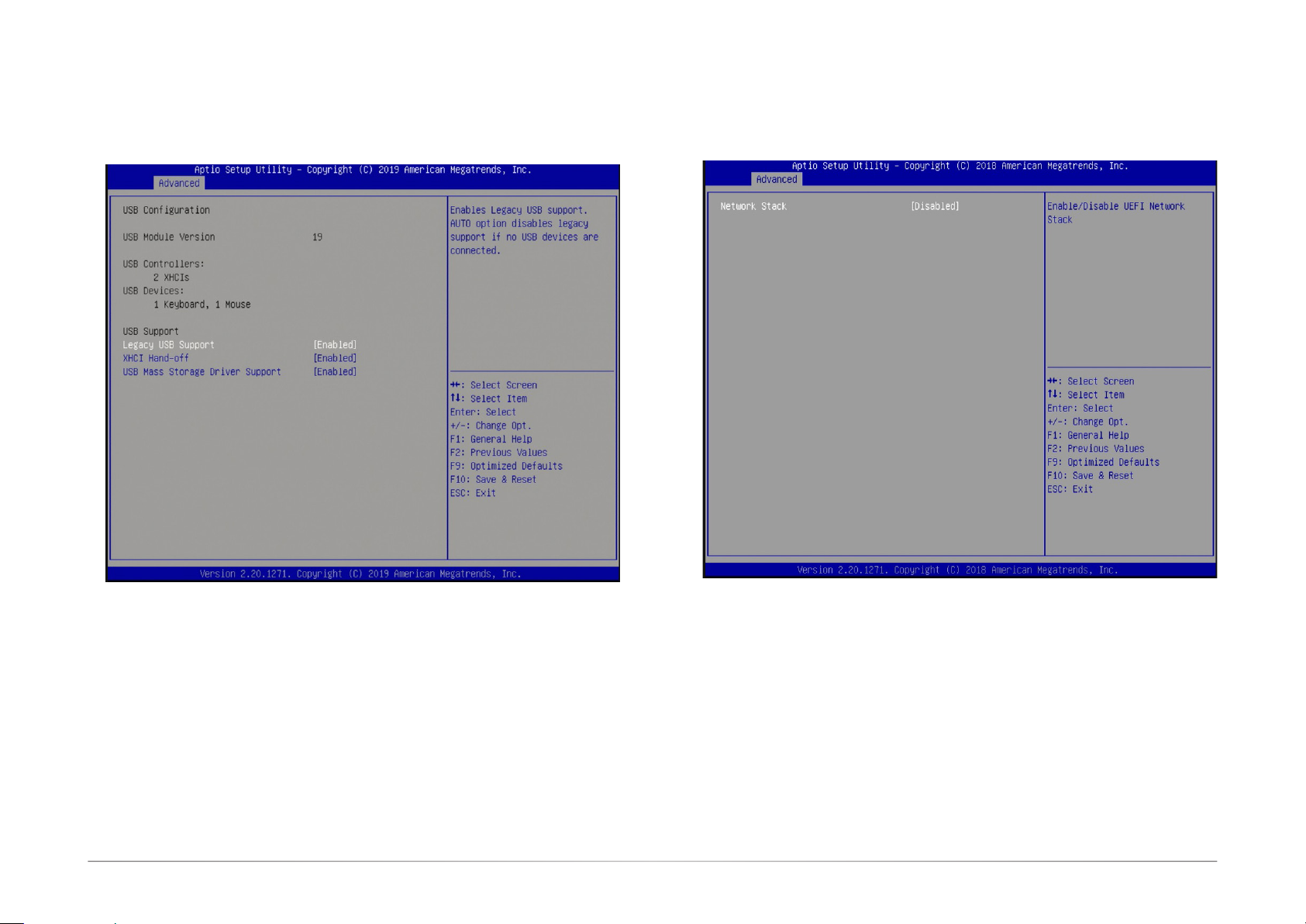
USB Configuration
This section configures the parameters of USB devices.
Network Stack Configuration
This section enables or disables network stack settings.
Legacy USB Support
Enabled
Enables legacy USB.
Disabled
Keeps USB devices available only for EFI applications.
XHCI Hand-off
This is a workaround for OSes that do not support eXtensible Host Controller Interface
(xHCI) hand-off. The xHCI ownership change should be claimed by the xHCI driver.
USB Mass Storage Driver Support
Enable or disable the support for the USB Mass Storage Driver.
35User's Manual | GM341-GHF
Page 36
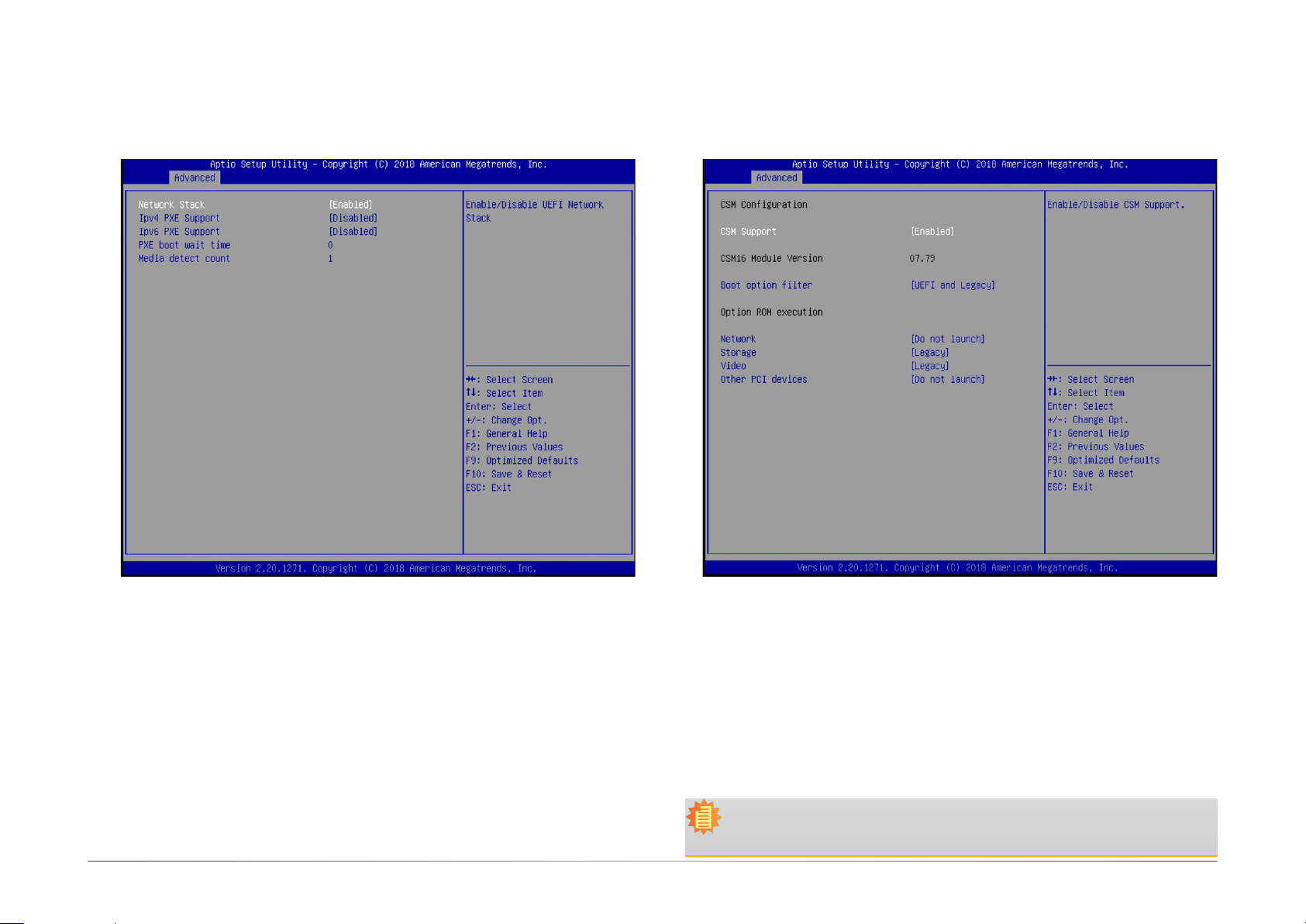
CSM Configuration
Chapter 7
When “Network Stack” is set to enabled, it displays the following configuration settings:
This section configures Compatibility Support Module (CSM) settings.
IPv4 PXE Support
Enable or disable Preboot eXecution Environment (PXE) boot to LAN using IPv4
addressing architecture.
IPv6 PXE Support
Enable or disable Preboot eXecution Environment (PXE) boot to LAN using IPv6
addressing architecture.
PXE boot wait time
Enter the wait time value (seconds) to abort the PXE boot by pressing the ESC
key. Valid range is from 0 to 5 seconds.
Media detect count
Enter the number of times the presence of media will be checked. Valid range is
from 1 to 50 times.
CSM Support
Enable or disable the CSM support. When the CSM support is enabled, UEFI BIOS will be
able to execute legacy firmware drivers.
Boot option filter
Select the BIOS boot mode: UEFI and legacy, legacy only or UEFI only.
Network
Select to control the execution of network option ROM: Do not launch, UEFI or legacy.
Note:
When Secure Boot (please refer to "Security"> "Secure Boot" later in this chapter) is
enabled, execution of the CSM and legacy ROMs are not allowed.
36User's Manual | GM341-GHF
Page 37
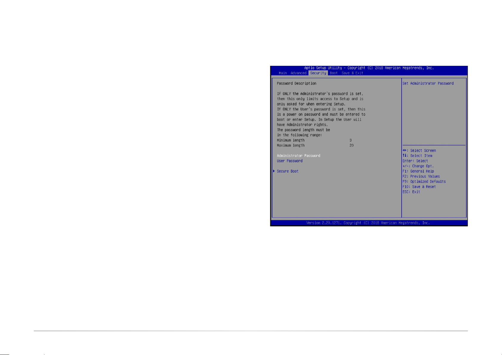
CSM Support
Enable or disable the CSM support. When the CSM support is enabled, UEFI BIOS will be able
to execute legacy firmware drivers.
Boot option filter
Select the BIOS boot mode: UEFI and legacy, legacy only or UEFI only.
Network
Select to control the execution of network option ROM: Do not launch, UEFI or legacy.
Storage
Select to control the execution of storage option ROM: Do not launch, UEFI or legacy.
Video
Select to control the execution of video option ROM: Do not launch, UEFI or legacy.
Other PCI devices
Select to control the execution of option ROM for other PCI devices other than the above configured network, storage and video devices: Do not launch, UEFI or legacy.
Chapter 7
Security
This section configures the security for system boot and BIOS setup utility.
Administrator Password
Enter to set a new or change the existing administrator password.
User Password
Enter to set a new or change the existing user password.
Please note that passwords must be at least 3 and up to 20 characters long.
37User's Manual | GM341-GHF
Page 38
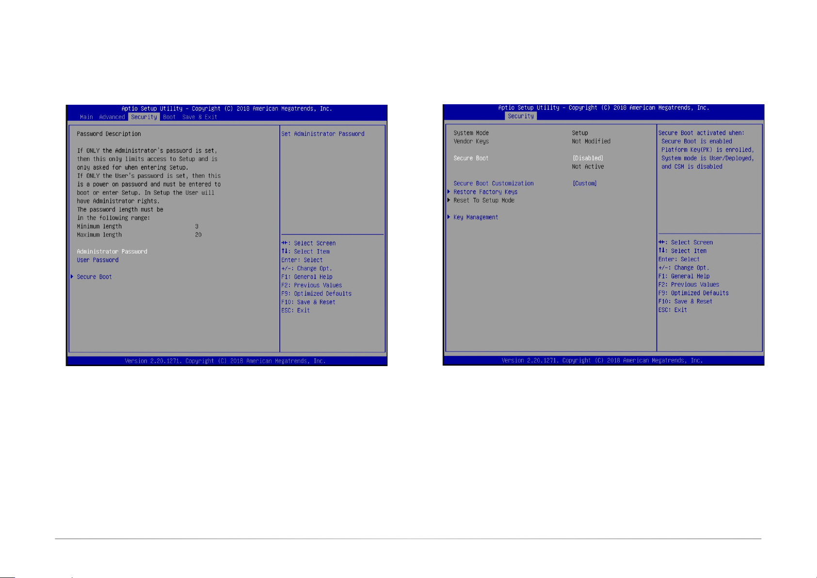
Secure Boot
This section configures Secure Boot settings. This function is designed for advanced users; be
careful when changing these settings. It’s possible to cause the system not to start properly.
Chapter 7
Secure Boot
Secure Boot helps ensure that the system boot executes only firmware that is trusted by
the manufacturer. This function can be enabled if the Platform Key (PK) is enrolled, and the
System Mode is user/deployed and the CSM (please refer to “Advanced” > “CSM Configuration” earlier in this chapter) is disabled.
Secure Boot Customization
Select Custom to customize the "Secure Boot" function or "Standard" to use the standard
feature. If it is set to "Custom", the following functions can be congured:
Restore Factory Keys
Select "Yes" to force the system to use the factory defaults settings. It will set the system to
be in the "User Mode". It will also congure the NVRAM to contain pre-dened factory default
Secure Boot keys.
Reset To Setup Mode
Select "Yes" to delete all UEFI secure boot keys stored in the NVRAM. It will also
revert the system back to the Setup mode.
Key Management
Manage Secure Boot keys such as Platform Key and Key Exchange Keys.
38User's Manual | GM341-GHF
Page 39
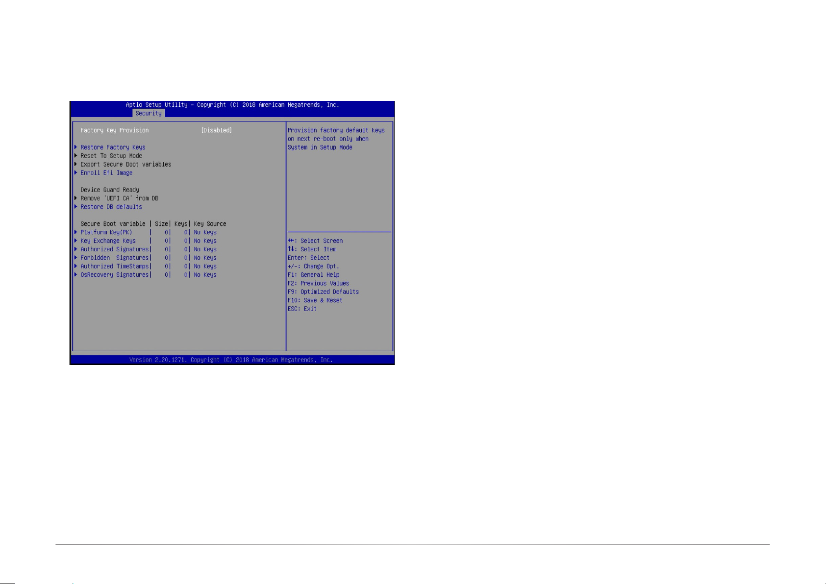
Key Management
This section creates and manages the Secure Boot keys and certificates.
Chapter 7
Enroll E Image
Enroll a SHA256 certicate of a PE image into the authorized signature database (DB) to
allow the image to run in the Secure Boot mode.
Remove UEFI CA from DB
Remove the Microsoft UEFI CA certicate from the authorized signature DB.
Restore DB defaults
Restore DB variables to their factory defaults. You may also proceed to the next section:
"Secure Boot Variable" to congure DB variables, including Platform Key (PK), Key Exchange
Keys, Authorized Signatures, Forbidden Signatures, Authorized TimeStamps, OsRecovery
Signatures. For each variable, you can choose to show the detailed information of the key(s)
and export, update, append or delete the key(s).
Factory Key Provision
When the system is in the Setup Mode, you can provision the system with a configured
factory default key.
Restore Factory Keys
Select "Yes" to force the system to use the factory default settings. It will set the system to
be in the User Mode. It will also congure the NVRAM to contain pre-dened factory default
secure boot keys.
Reset To Setup Mode
Select "Yes" to delete all UEFI Secure Boot key stored in the NVRAM. It will also revert the
system back to the Setup Mode.
Export Secure Boot Variables
Export the NVRAM content of Secure Boot configurations to a file in the root folder of a
selected le system device.
39User's Manual | GM341-GHF
Page 40
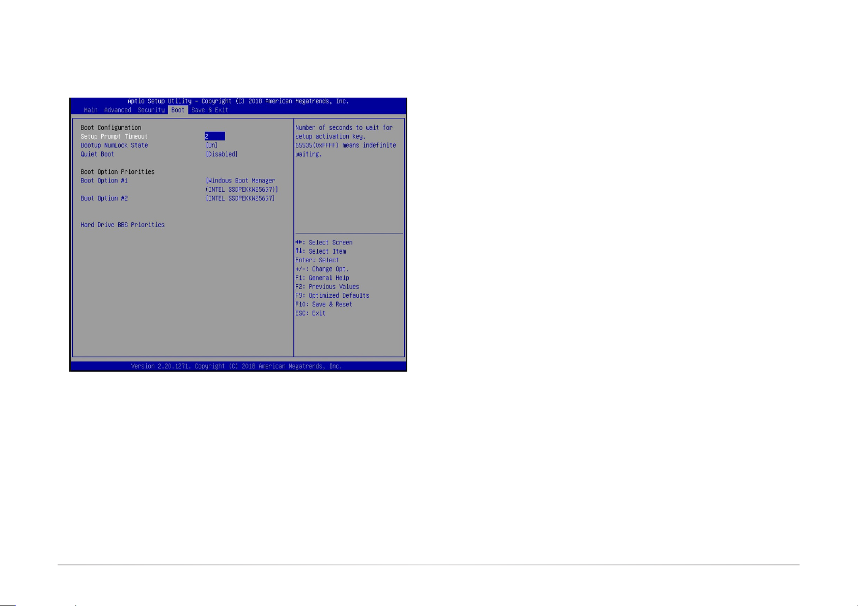
Boot
Chapter 7
Boot Option #1/#2
Set the boot order of the system boot devices.
Hard Drive BBS Priorities
Set the boot order of the devices in this group.
Setup Prompt Timeout
Select the number of seconds to wait for the BIOS setup activation key. 65535 (0xFFFF)
denotes indefinite waiting.
Bootup NumLock State
This option allows you to determine the default state of the numeric keypad. By default,
the system boots up with NumLock on and the function of the numeric keypad is the number keys. When it is set to Off, the function of the numeric keypad is the arrow keys.
Quiet Boot
Enable or disable the quiet boot function to configure the screen’s display between POST
messages or the OEM logo at bootup. Select Disabled to display the POST messages and
select Enabled to display the OEM logo.
40User's Manual | GM341-GHF
Page 41
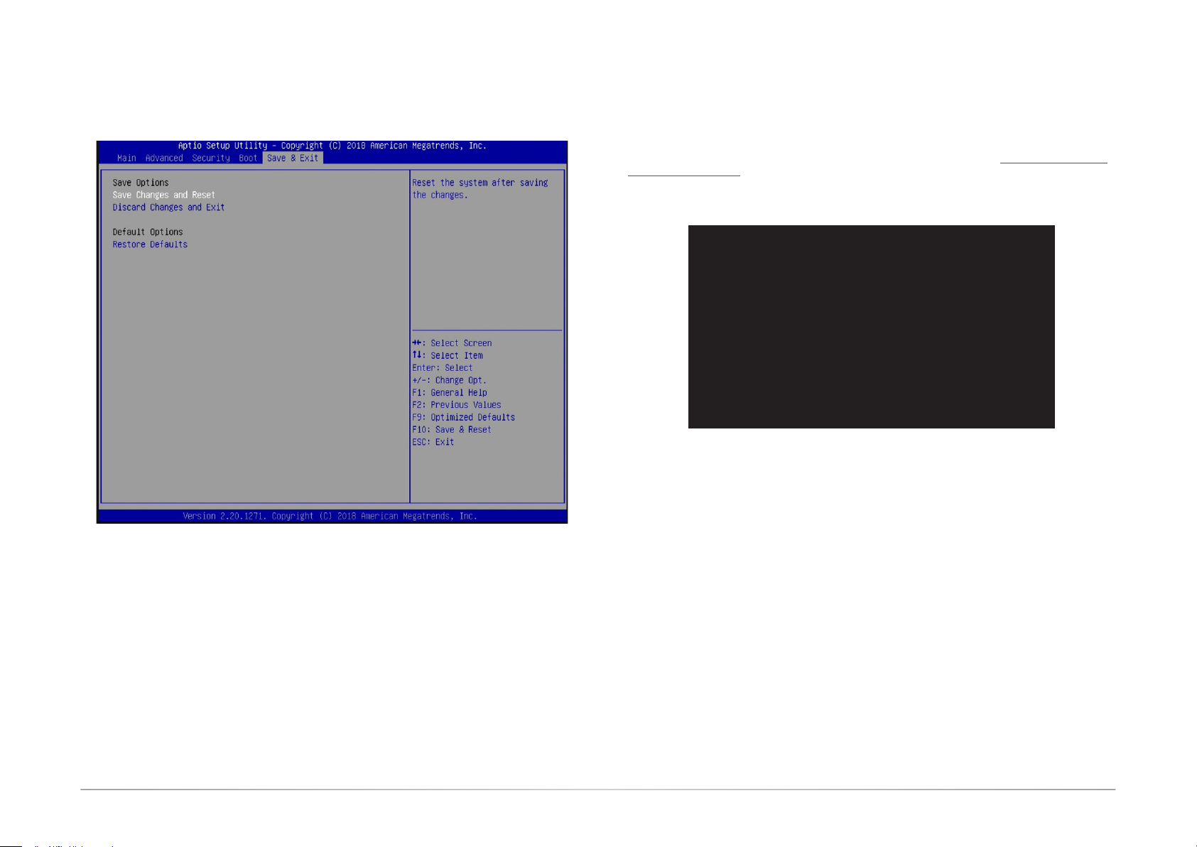
Chapter 7
Save & Exit
Updating the BIOS
To update the BIOS, you will need the new BIOS file and a flash utility. Please contact technical support or your sales representative for the latest BIOS file and the firmware update utility.
For instructions on how to update BIOS with the flash utility, please see https://www.dfi.com/
tw/knowledge/video/5 from the Knowledge Base of the DFI website.
C:\AFU\AFUDOS>afudos lename /B /P /N
+--------------------------------------------------------------------------------------------------------+
|
|
+--------------------------------------------------------------------------------------------------------+
Reading le ..............................
Erasing ash .............................
Writing ash .............................
Verifying ash ..........................
Erasing BootBlock ....................
Writing BootBlock ....................
Verifying BootBlock .................
C:\AFU\AFUDOS>
AMI Firmware Update Utility(APTIO) v2.25
Copyright (C)2008 American Megatrends Inc. All Rights Reserved.
done
done
done
done
done
done
done
|
|
Save Changes and Reset
To save the changes, select this field and then press <Enter>. A dialog box will appear. Select “Yes” to reset the system after saving all changes.
Discard Changes and Exit
To discard the changes, select this field and then press <Enter>. A dialog box will
appear. Select “Yes” to reset system setup configurations without saving any changes.
Restore Defaults
To restore and load the optimized default values, select this field and then press
<Enter>. A dialog box will appear. Select “Yes” to restore the default values of all the
setup options.
41User's Manual | GM341-GHF
Page 42

Chapter 8 - Supported Software
The system requires you to install drivers for some devices to operate properly. To download
the latest driver, please go to the DFI Download Center:
http://www.dfi.com/DownloadCenter
Once you are in the Download Center page, select your product or type the model name and
click “Search” to find product-related resources such as documentation and drivers.
Drivers are available for the following devices in Windows 10:
• AMD® Chipset and VGA Drivers
• Realtek RTL8119 LAN Drivers
• Gaming Drivers
Chapter 8
42User's Manual | GM341-GHF
Page 43
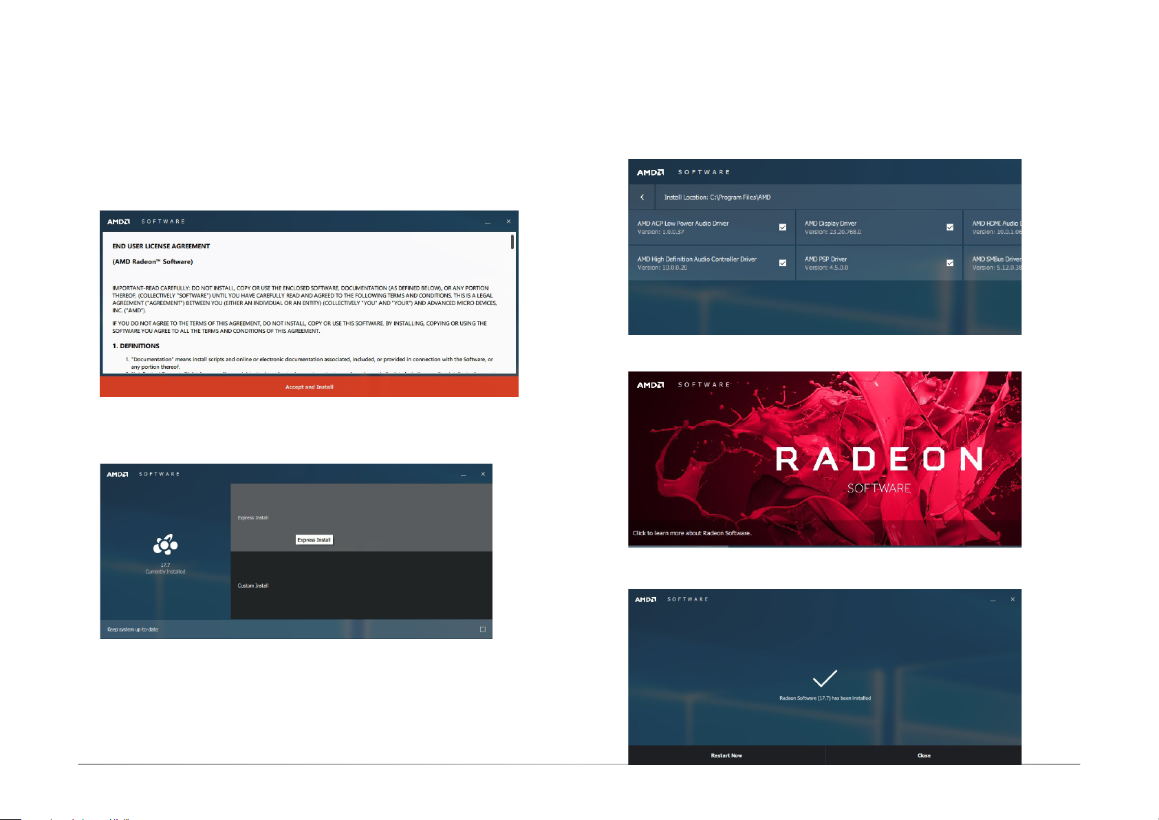
AMD® Chipset and VGA Drivers
Chapter 8
The AMD Radeon™ software provides drivers and conguration utilities for AMD Radeon™
Vega 11 Graphics. To install this software, click the executable le to begin the installation.
1. Read the End User License Agreement then click “Accept and Install” to continue the
installation or click on X to stop the installation.
2. Choose between “Express Install” or “Custom Install”. The “Express Install” installs all
the programs in the default folder.
3. The “Custom Install” provides the option to select the programs that you would like to
install and the folder for installation.
4. Please wait while the software and drivers are being installed.
5. Once the Radeon ™ Software has been successfully installed, choose “Restart Now”.
43User's Manual | GM341-GHF
Page 44

Realtek LAN Drivers
The onboard LAN ports are provided by Realtek Gigabit Ethernet controllers. To install the
driver, click the executable file inside the LAN Driver folder.
1. After the software package has done preparing the software package, click “Next”
to continue.
2. Click “Install” to start the installation.
Chapter 8
3. Click “Finish” to exit the wizard after the installation is complete.
44User's Manual | GM341-GHF
Page 45
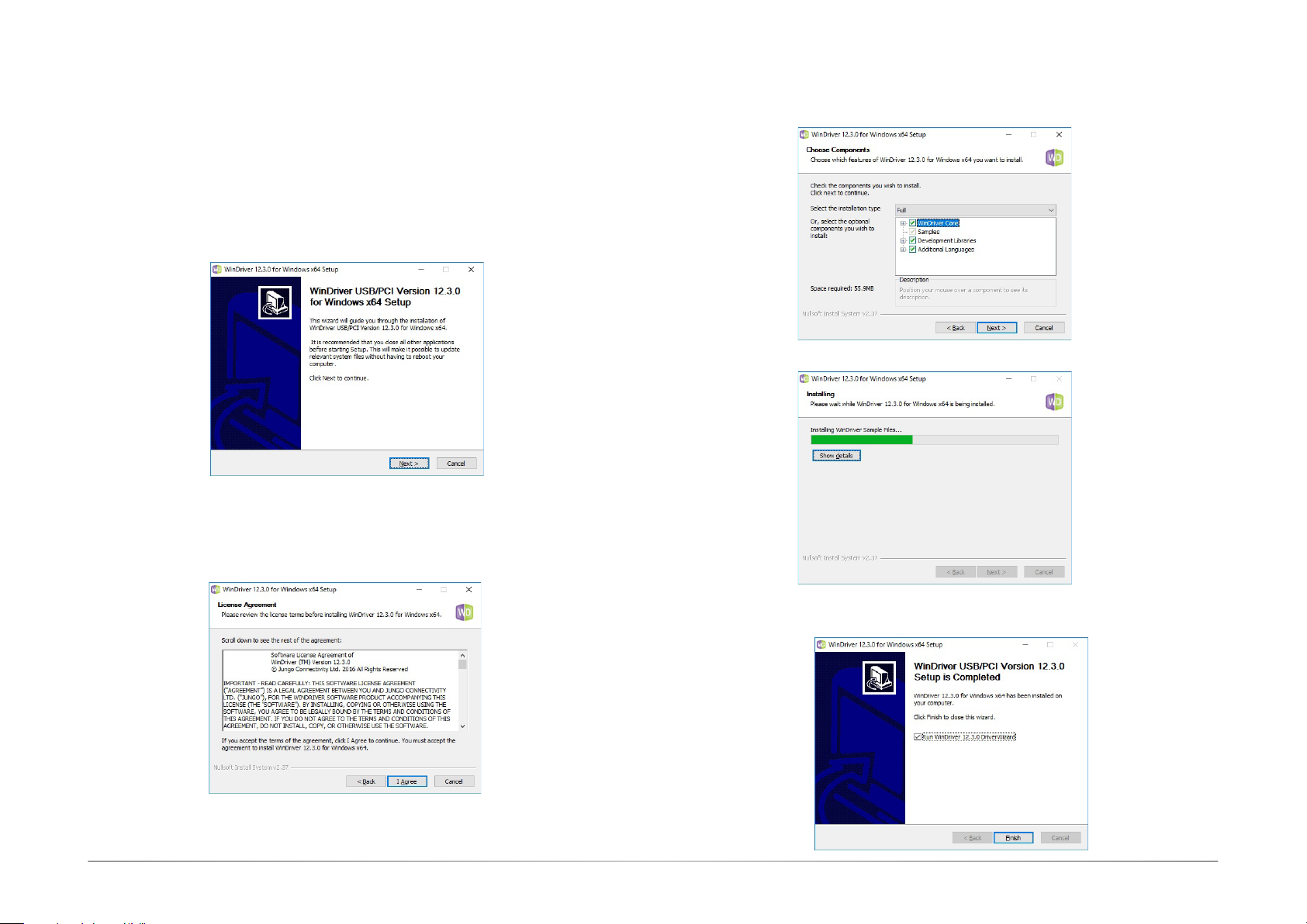
Chapter 8
WinDriver
The gaming platform employs digital input/output devices. For the digital I/O functions to work
properly, the WinDriver USB/PCI driver must be installed. To install the driver, click the executable file inside the gaming driver folder.
1. Setup is now ready to install WinDriver USB/PCI Version 12.3.0. Click “Next” to continue.
2. Read the license agreement then click “Yes” to continue.
3. Follow the on-screen instructions to complete the rest of the installation process.
4. Please wait while the Setup is installing the driver.
5. Click “Finish” to exit the Setup wizard.
45User's Manual | GM341-GHF
 Loading...