

Page 1

CR100-CRM
System Board
User’s Manual
A19140442
Page 2

Copyright
This publication contains information that is protected by copyright. No part of it
may be reproduced in any form or by any means or used to make any transformation/adaptation without the prior written permission from the copyright holders.
This publication is provided for informational purposes only. The manufacturer
makes no representations or warranties with respect to the contents or use
of this manual and specifically disclaims any express or implied warranties of
merchantability or fitness for any particular purpose. The user will assume the
entire risk of the use or the results of the use of this document. Further, the
manufacturer reserves the right to revise this publication and make changes to
its contents at any time, without obligation to notify any person or entity of such
revisions or changes.
Changes after the publication’s first release will be based on the product’s revision. The website will always provide the most updated information.
© 2014. All Rights Reserved.
Trademarks
All trademarks and registered trademarks of products appearing in this manual
are the properties of their respective holders.
Page 3

FCC and DOC Statement on Class B
This equipment has been tested and found to comply with the limits for a Class B
digital device, pursuant to Part 15 of the FCC rules. These limits are designed to
provide reasonable protection against harmful interference when the equipment
is operated in a residential installation. This equipment generates, uses and can
radiate radio frequency energy and, if not installed and used in accordance with
the instruction manual, may cause harmful interference to radio communications.
However, there is no guarantee that interference will not occur in a particular
installation. If this equipment does cause harmful interference to radio or television reception, which can be determined by turning the equipment off and on,
the user is encouraged to try to correct the interference by one or more of the
following measures:
• Reorient or relocate the receiving antenna.
• Increase the separation between the equipment and the receiver.
• Connect the equipment into an outlet on a circuit different from that to which
the receiver is connected.
• Consult the dealer or an experienced radio TV technician for help.
Notice:
1. The changes or modifications not expressly approved by the party responsible
for compliance could void the user’s authority to operate the equipment.
2. Shielded interface cables must be used in order to comply with the emission
limits.
Page 4

1
Introduction
Table of Contents
Copyright ...........................................................................................2
Trademarks ........................................................................................ 2
FCC and DOC Statement on Class B .............................................. 3
About this Manual ............................................................................. 6
Warranty .......................................................................................... 6
Static Electricity Precautions ............................................................. 7
Safety Measures ................................................................................. 7
About the Package ............................................................................ 8
Before Using the System Board ........................................................ 8
Chapter 1 - Introduction ..................................................................9
Specifications .................................................................................. 9
Features ...................................................................................... 12
Chapter 2 - Hardware Installation .................................................. 15
System Board Layout .................................................................... 15
System Memory ........................................................................... 16
Installing the DIM Module ......................................................... 17
CPU ............................................................................................ 19
Installing the CPU .................................................................... 19
Installing the Fan and Heat Sink ................................................ 21
Jumper Settings ............................................................................. 23
Clear CMOS Data ..................................................................... 23
PS/2 Power Select .................................................................... 24
USB Power Select ..................................................................... 25
Panel Power Select ................................................................... 26
COM1/COM2 RS232/RS422/RS485 Select.................................... 27
COM1/COM2 RS232/Power Select............................................... 28
Power-on Select ....................................................................... 29
CompactFlash Card Setting ....................................................... 30
Rear Panel I/O Ports ..................................................................... 31
PS/2 Keyboard/Mouse Port ........................................................ 32
COM (Serial) Ports ................................................................... 33
HDMI Port ............................................................................... 34
DVI-I Port ............................................................................... 35
RJ45 LAN Ports ........................................................................ 36
USB Ports................................................................................ 37
Audio ...................................................................................... 39
I/O Connectors ............................................................................ 41
S/PDIF Connector ..................................................................... 41
4
Page 5

Introduction
LVDS LCD Panel Connector ........................................................ 42
LCD/Inverter Power Connector ................................................... 42
Digital I/O Connectors .............................................................. 44
SATA (Serial ATA) Connectors .................................................... 45
Cooling Fan Connectors ............................................................. 46
Chassis Instrusion Connector .................................................... 47
Power Connectors .................................................................... 48
Standby Power LED .................................................................. 49
Front Panel Connectors ............................................................. 50
Expansion Slots ....................................................................... 51
Battery ................................................................................... 54
Chapter 3 - BIOS Setup .................................................................. 56
Overview .............................................................................................................. 56
AMI BIOS Setup Utility ................................................................. 58
Main ....................................................................................... 58
Advanced ................................................................................ 59
Chipset ................................................................................... 79
Boot ....................................................................................... 87
Security .................................................................................. 89
Save & Exit ............................................................................. 90
Updating the BIOS ........................................................................ 91
Notice: BIOS SPI ROM .................................................................. 92
1
Chapter 4 - Supported Software ................................................... 93
Chapter 5 - RAID ........................................................................ 126
RAID Levels .......................................................................................................126
Settings ................................................................................................................127
Chapter 6 - Intel AMT Settings ................................................... 131
Overview ............................................................................................................131
Enable Intel® AMT in the AMI BIOS ............................................................132
Enable Intel® AMT in the Intel® Management Engine BIOS
Extension (MEBX) Screen ..............................................................................
134
Appendix A - NLITE and AHCI Installation Guide ....................... 159
Appendix B - Watchdog Sample Code ......................................... 171
Appendix C - System Error Message ............................................ 172
Appendix D - Troubleshooting ...................................................... 174
5
Page 6

1
Introduction
About this Manual
An electronic file of this manual is included in the CD. To view the user’s manual
in the CD, insert the CD into a CD-ROM drive. The autorun screen (Main Board
Utility CD) will appear. Click “User’s Manual” on the main menu.
Warranty
1. Warranty does not cover damages or failures that arised from misuse of the
product, inability to use the product, unauthorized replacement or alteration
of components and product specifications.
2. The warranty is void if the product has been subjected to physical abuse,
improper installation, modification, accidents or unauthorized repair of the
product.
3. Unless otherwise instructed in this user’s manual, the user may not, under
any circumstances, attempt to perform service, adjustments or repairs on the
product, whether in or out of warranty. It must be returned to the purchase
point, factory or authorized service agency for all such work.
4. We will not be liable for any indirect, special, incidental or consequencial
damages to the product that has been modified or altered.
6
Page 7

Introduction
Static Electricity Precautions
It is quite easy to inadvertently damage your PC, system board, components
or devices even before installing them in your system unit. Static electrical discharge can damage computer components without causing any signs of physical
damage. You must take extra care in handling them to ensure against electrostatic build-up.
1. To prevent electrostatic build-up, leave the system board in its anti-static bag
until you are ready to install it.
2. Wear an antistatic wrist strap.
3. Do all preparation work on a static-free surface.
4. Hold the device only by its edges. Be careful not to touch any of the components, contacts or connections.
5. Avoid touching the pins or contacts on all modules and connectors. Hold
modules or connectors by their ends.
1
Important:
Electrostatic discharge (ESD) can damage your processor, disk drive and
other components. Perform the upgrade instruction procedures described
at an ESD workstation only. If such a station is not available, you can
provide some ESD protection by wearing an antistatic wrist strap and
attaching it to a metal part of the system chassis. If a wrist strap is
unavailable, establish and maintain contact with the system chassis
throughout any procedures requiring ESD protection.
Safety Measures
To avoid damage to the system:
• Use the correct AC input voltage range.
To reduce the risk of electric shock:
• Unplug the power cord before removing the system chassis cover for installation or servicing. After installation or servicing, cover the system chassis
before plugging the power cord.
Battery:
• Danger of explosion if battery incorrectly replaced.
• Replace only with the same or equivalent type recommend by the manufacturer.
• Dispose of used batteries according to local ordinance.
7
Page 8

1
Introduction
About the Package
The system board package contains the following items. If any of these items are
missing or damaged, please contact your dealer or sales representative for assistance.
One CR100-CRM motherboard
Two Serial ATA data cables
Two COM port cables (with bracket)
One USB port cable (with bracket)
One I/O shield
One DVD
One QR (Quick Reference)
Optional Items
USB port cable
COM port cable
Serial ATA data cable
Serial ATA power cable
I/O shield
The system board and accessories in the package may not come similar to the
information listed above. This may differ in accordance to the sales region or
models in which it was sold. For more information about the standard package in
your region, please contact your dealer or sales representative.
Before Using the System Board
Before using the system board, prepare basic system components.
If you are installing the system board in a new system, you will need at least the
following internal components.
• A CPU
• Memory module
• Storage devices such as hard disk drive, CD-ROM, etc.
You will also need external system peripherals you intend to use which will normally include at least a keyboard, a mouse and a video display monitor.
8
Page 9
Chapter 1 - Introduction
Specifications
1
Introduction
Processor
Chipset
System Memory
Expansion Slots
• Socket G2 988B for:
- 3rd Generation Intel
(22nm process technology)
: Intel
: Intel
: Intel
- 2nd Generation Intel
(32nm process technology)
: Intel
: Intel
: Intel
: Intel
• Intel® QM77 Express chipset
• Two 204-pin SODIMM sockets
• Supports DDR3 SODIMM
DDR3 1066/1333/1600MHz DDR3 1066/1333MHz
DDR3 1600MHz (i7)
• Supports DDR3L SODIMM
- 1066/1333MHz when operating at 1.35V
- 1066/1333/1600MHz when operating at 1.5V
• Supports dual channel memory interface
• Supports up to 16GB system memory
• DRAM device technologies: 1Gb, 2Gb and 4Gb DDR3 DRAM
technologies are supported for x8 and x16 devices, unbuffered, non-ECC
• 1 PCIe x16 slot
- Supports Gen 3.0 (3rd generation processors)
- Supports Gen 2.0 (2nd generation processors)
- Configurations (supported only via a riser card):
: One x8 (GFX) and two x4 (I/O)
: Two x8 (GFX, I/O)
: One x16 (GFX, I/O)
• 2 DFI Proprietary Extension Bus for PCIe/PCI expansion
• 1 Mini PCIe slot (PCIe and USB signals)
- Supports half size Mini PCIe card
®
Core™ i7-3610QE (6M Cache, up to 3.3 GHz); 45W
®
Core™ i5-3610ME (3M Cache, up to 3.3 GHz); 35W
®
Core™ i3-3120ME (3M Cache, 2.4 GHz); 35W
®
Core™ i7-2710QE (6M Cache, up to 3.0 GHz); 45W
®
Core™ i5-2510E (3M Cache, up to 3.1 GHz); 35W
®
Core™ i3-2330E (3M Cache, 2.2 GHz); 35W
®
Celeron® B810 (2M Cache, 1.6 GHz); 35W
3rd Generation Processors 2nd Generation Processors
®
CoreTM processors
®
CoreTM processors
(i5/i3/Celeron)
9
Page 10

1
Introduction
Graphics
Audio
LAN
Serial ATA
Intel Active
Management
Technology
(AMT)
• Intel® HD Graphics 4000
• Display ports: HDMI, 2 DVI-I (1 supports DVI-D signal only),
and LVDS
•
HDMI and DVI: resolution up to 1920x1200 @60Hz
• VGA: resolution up to 2048x1536 @75Hz, 32-bit
• LVDS: Single Channel - 18/24-bit; Dual Channel - 36/48-bit,
resolution up to 1920x1200 @60Hz
• Intel
• DirectX Video Acceleration (DXVA) for accelerating video
• Supports DirectX 11/10.1/10/9 and OpenGL 3.0
• Realtek ALC886 5.1-channel High Definition Audio
• Audio outputs: Mic-in/Center+Subwoofer, Line-in/Surround
• S/PDIF audio interface
• Intel
• Intel
• Integrated 10/100/1000 transceiver
• Fully compliant with IEEE 802.3, IEEE 802.3u, IEEE 802.3ab
• 4 Serial ATA ports
- 2 SATA 3.0 ports with data transfer rate up to 6Gb/s
- 2 SATA 2.0 ports with data transfer rate up to 3Gb/s
• Integrated Advanced Host Controller Interface (AHCI) con-
• Supports RAID 0/1/5/10
• Supports iAMT8.0
• Out-of-band system access
• Remote troubleshooting and recovery
• Hardware-based agent presence checking
• Proactive alerting
• Remote hardware and software asset tracking
®
Clear Video Technology
processing - Full AVC/VC1/MPEG2 HW Decode
and Line-out
®
WG82579LM with iAMT8.0 Gigabit Ethernet Phy
®
WG82574L PCI Express Gigabit Ethernet controller
troller
10
TPM (optional)
USB interface
Rear Panel I/O
Ports
• Provides a Trusted PC for secure transactions
• Provides software license protection, enforcement and password protection
• XHCI Host Controller supports up to 4 super speed USB 3.0
ports
• 1 mini-DIN-6 port for PS/2 mouse/keyboard
• 4 USB 3.0/2.0/1.1 ports
• 2 USB 2.0/1.1 ports
• 1 DB-9 serial port
- Supports RS232/422/485 (RS232 and/or Power)
• 1 HDMI port
• 2 DVI-I ports (1 supports DVI-D signal only)
• 2 RJ45 LAN ports
• Mic-in/Center+Subwoofer, Line-in/Surround and Line-out
jacks
Page 11

Introduction
1
I/O Connectors
BIOS
Energy Efficient
Design
Damage Free
Intelligence
Power
Consumption
Temperature
Humidity
OS Support
Dimensions
• 2 connectors for 4 external USB 2.0/1.1 ports
• 5 connectors for 5 external serial ports
- 1 RS232/422/485 (RS232 and/or Power)
- 4 RS232
• 1 LVDS LCD panel connector
• 1 LCD/inverter power connector
• 1 8-bit Digital I/O connector
• 1 front audio connector for line-out and mic-in jacks
• 1 S/PDIF connector
• 4 Serial ATA ports (2 SATA 3.0; 2 SATA 2.0)
• 1 24-pin ATX power connector
• 1 chassis intrusion connector
• 1 front panel connector
• 2 fan connectors
• AMI BIOS
• 64Mbit SPI BIOS
• Supports ErP Lot6 power saving (optional)
• ACPI v3.0 specification
• System Power Management
• Wake-On-Events include:
- Wake-On-PS/2 KB/Mouse
- Wake-On-USB KB/Mouse
- Wake-On-LAN
- RTC timer to power-on the system
• AC power failure recovery
• Monitors CPU/system temperature and overheat alarm
• Monitors VCORE/1.05V/DDR/3.3V/5V/12V voltages and failure alarm
• Monitors CPU/system fan speed and failure alarm
• Read back capability that displays temperature, voltage and
fan speed
• Watchdog timer function
- Watchdog timeout programmable via software from 1 to
255 seconds
• 42.86W with i7-3610QE at 2.3GHz and 2x 1GB DDR3 SODIMM
• Operating: 0
• Storage: -20
• 10% to 90%
o
C to 60oC
o
C to 85oC
• Windows XP Professional x86 & SP3 (32-bit)
• Windows XP Professional x64 & SP2 (64-bit)
• Windows 7 Ultimate x86 & SP1 (32-bit)
• Windows 7 Ultimate x64 & SP1 (64-bit)
• Windows 8 Enterprise x86 (32-bit)
• Windows 8 Enterprise x64 (64-bit)
• Mini-ITX form factor
- 170mm (6.7”) x 170mm (6.7”)
• Heat spreader with heat sink and fan
- 62mm x 60mm x 42mm
Certification
• CE, FCC Class B, UL, RoHS
11
Page 12

1
Introduction
Features
Watchdog Timer
The Watchdog Timer function allows your application to regularly “clear” the system at the set time interval. If the system hangs or fails to function, it will reset
at the set time interval so that your system will continue to operate.
DDR3
DDR3 delivers increased system bandwidth and improved performance. It offers
peak data transfer rate of up to 16Gb/s bandwidth. The advantages of DDR3
are its higher bandwidth and its increase in performance at a lower power than
DDR2.
Graphics
The integrated Intel HD graphics for graphics intensive applications delivers
exceptional 3D, 2D and video capabilities. It supports 3 independent displyas:
HDMI, DVI-I and LVDS interfaces.
DVI
DVI (Digital Visual Interface) is a form of video interface technology made to
maximize the quality of flat panel LCD monitors and modern video graphics
cards. Data is transmitted using the TMDS (Transition Minimized Differential Signaling) protocol, providing a digital signal from the PC’s graphics subsystem to
the display.
PCI Express
PCI Express is a high bandwidth I/O infrastructure that possesses the ability to
scale speeds by forming multiple lanes. The PCI Express architecture provides a
high performance graphics infrastructure by enhancing the capability of a x16 PCI
Express lane to provide 4 Gigabytes per second transfer rate.
Intel Active Management Technology (AMT)
Intel Active Management Technology (Intel® AMT) allows remote access and management of networked systems even while PCs are powered off, remotely repair
systems after OS failures and has the capability to remotely update all systems
with the latest security software.
Audio
12
The Realtek ALC886 audio codec provides 5.1-channel High Definition audio output.
Page 13

Introduction
Serial ATA
Serial ATA is a storage interface that is compliant with SATA 1.0a specification. SATA 3.0 supports speed up to 6Gb/s while SATA 2.0 supports speed up to
3Gb/s. This improves hard drive performance faster than the standard parallel
ATA whose data transfer rate is 100MB/s. The board supports RAID 0/1/5/10.
Gigabit LAN
The Intel WG82579LM PHY and Intel WG82574L PCI Express Gigabit controllers
support up to 1Gbps data transmission.
USB
The system board supports the new USB 3.0. It is capable of running at a maximum transmission speed of up to 5 Gbit/s (625 MB/s) and is faster than USB 2.0
(480 Mbit/s, or 60 MB/s) and USB 1.1 (12Mb/s). USB 3.0 reduces the time required for data transmission, reduces power consumption, and is backward compatible with USB 2.0. It is a marked improvement in device transfer speeds
between your computer and a wide range of simultaneously accessible external Plug and Play peripherals.
1
Wake-On-LAN
This feature allows the network to remotely wake up a Soft Power Down (SoftOff) PC. It is supported via the onboard LAN port or via a PCI LAN card that uses
the PCI PME (Power Management Event) signal. However, if your system is in the
Suspend mode, you can power-on the system only through an IRQ or DMA interrupt.
Important:
The 5V_standby power source of your power supply must support
≥720mA.
Wake-On-PS/2
This function allows you to use the PS/2 keyboard or PS/2 mouse to power-on
the system.
Important:
The 5V_standby power source of your power supply must support
≥720mA.
13
Page 14

1
Introduction
Wake-On-USB
This function allows you to use a USB keyboard or USB mouse to wake up a system from the S3 (STR - Suspend To RAM) state.
Important:
If you are using the Wake-On-USB Keyboard/Mouse function for 2 USB
ports, the 5V_standby power source of your power supply must support
≥1.5A. For 3 or more USB ports, the 5V_standby power source of your
power supply must support ≥2A.
RTC Timer
The RTC installed on the system board allows your system to automatically power-on on the set date and time.
ACPI STR
The system board is designed to meet the ACPI (Advanced Configuration and
Power Interface) specification. ACPI has energy saving features that enables PCs
to implement Power Management and Plug-and-Play with operating systems that
support OS Direct Power Management. ACPI when enabled in the Power Management Setup will allow you to use the Suspend to RAM function.
With the Suspend to RAM function enabled, you can power-off the system at
once by pressing the power button or selecting “Standby” when you shut down
Windows
closing files, applications and operating system. This is because the system is
capable of storing all programs and data files during the entire operating session
into RAM (Random Access Memory) when it powers-off. The operating session will
resume exactly where you left off the next time you power-on the system.
®
without having to go through the sometimes tiresome process of
Important:
The 5V_standby power source of your power supply must support
720mA.
Power Failure Recovery
When power returns after an AC power failure, you may choose to either poweron the system manually or let the system power-on automatically.
14
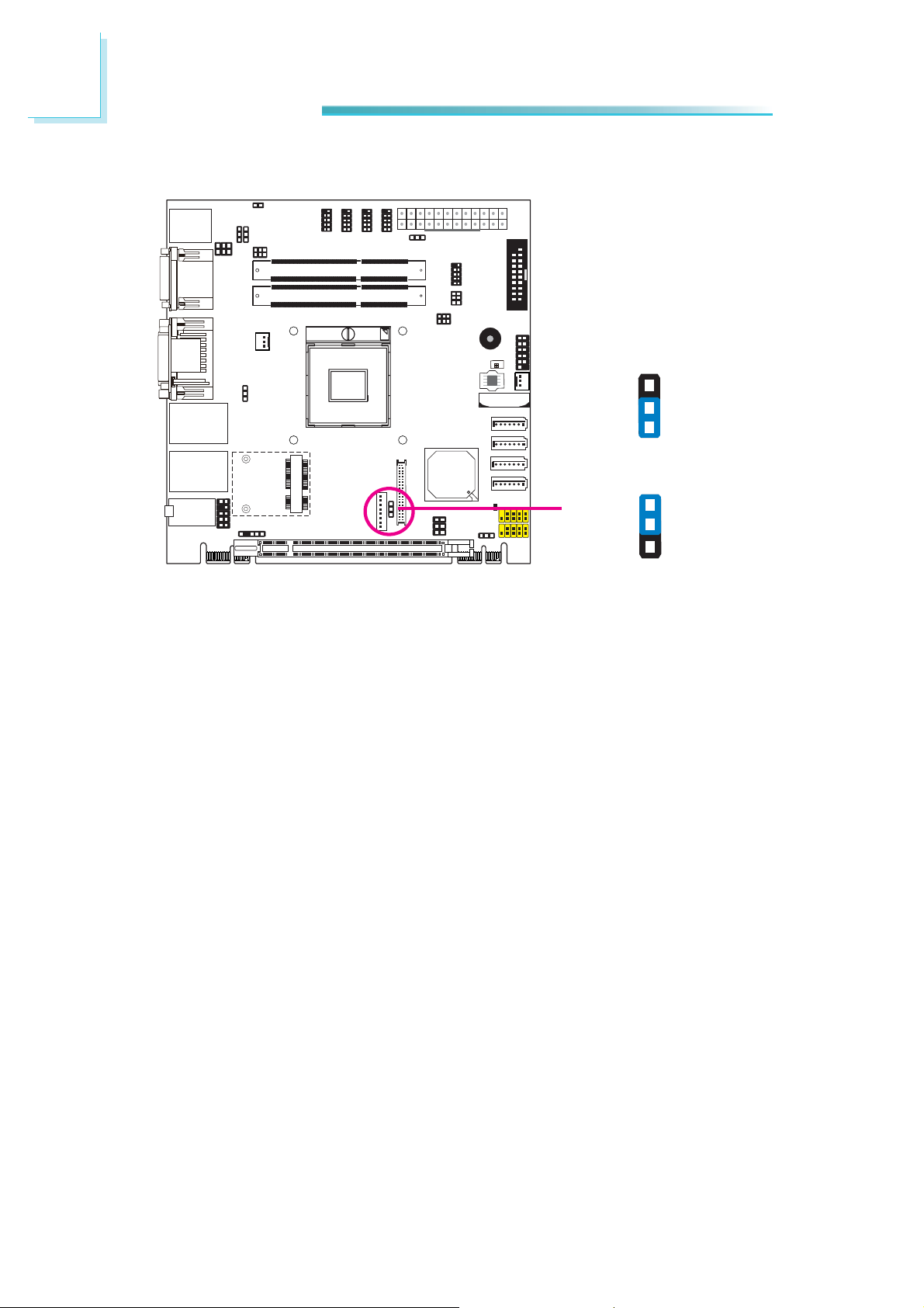
Page 15
Chapter 2 - Hardware Installation
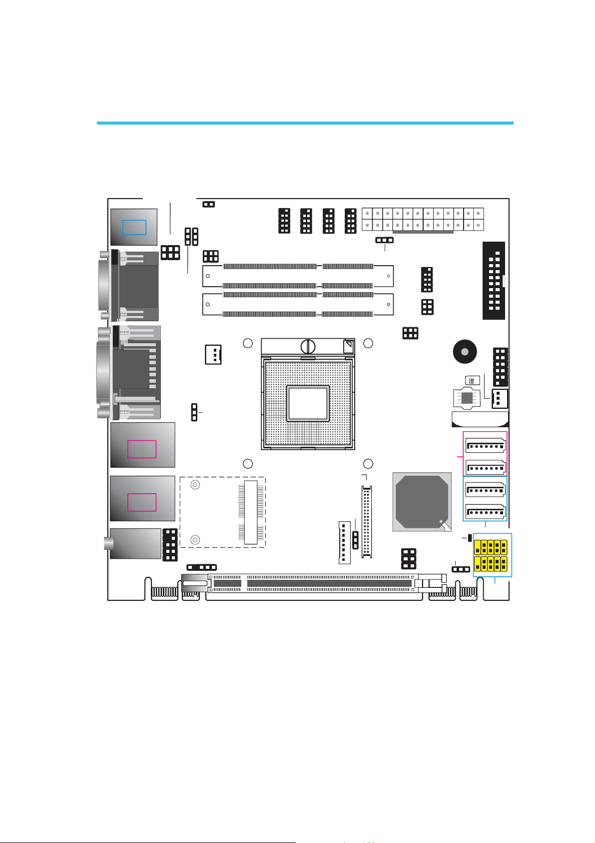
System Board Layout
COM1 RS232/Power
select (JP1)
PS/2 KB/MS
USB 9
USB 8
USB 2.0
COM 1
HDMI
DVI-I
DVI-I
JP1
2
1
USB 8-9 power
select ( )JP8
(Top: DVI-D signal only)
LAN 1
USB 1
USB 0
USB 3.0
LAN 2
USB 3
USB 2
USB 3.0
Line-in/ Surround
Line-out
Mic-in/ Center+Subwoofer
10
2
6
5
9
Front audio
1
1
1
1
1
PS/2 power
select (JP2)
2
1
1
CPU fan
USB 0-1/ 2-3 power
select (JP6)
1
Chassis
intrusion
6
COM1 RS232/422/485
select ( )JP4
5
S/PDIF
9
999
1
2
1
2
COM6
COM5
DDR3_2 SODIMM
DDR3_1 SODIMM
Socket G2
rPGA 988B
Mini PCIe
LCD/Inverter
PCIe x16
1
2
COM4
LVDS LCD
Backlight
level (JP11)
power
2
COM3
panel
1
1
1
1
13
Power-on
select ( )JP7
21
40 39
1
Hardware Installation
ATX Power
9
1
2
5
6
2
1
6
2
5
1
COM2 RS232/Power
select (JP3)
SPI Flash BIOS
SATA 3.0
Intel
QM77
Panel power
select ( )JP9
1
5
2
6
Power LED
Clear CMOS
COM2
COM2 RS232/
422/485 Select
(JP5)
Standby
Buzzer
SW1
(JP10)
1
12
24
System fan
ON
1
2
Battery
SATA 0
SATA 1
SATA 4
SATA 5
SATA 2.0
USB 6-7
9
10
9
USB 4-5
19
1
2
DIO
Front
panel
1
11
USB 2.0
1
1
1
1
1
2
1
2
1
2
PCIe x1 PCIe x1
15
Page 16
2
Hardware Installation
Important:
Electrostatic discharge (ESD) can damage your system board, processor,
disk drives, add-in boards, and other components. Perform the upgrade
instruction procedures described at an ESD workstation only. If such a
station is not available, you can provide some ESD protection by wearing
an antistatic wrist strap and attaching it to a metal part of the system
chassis. If a wrist strap is unavailable, establish and maintain contact
with the system chassis throughout any procedures requiring ESD protection.
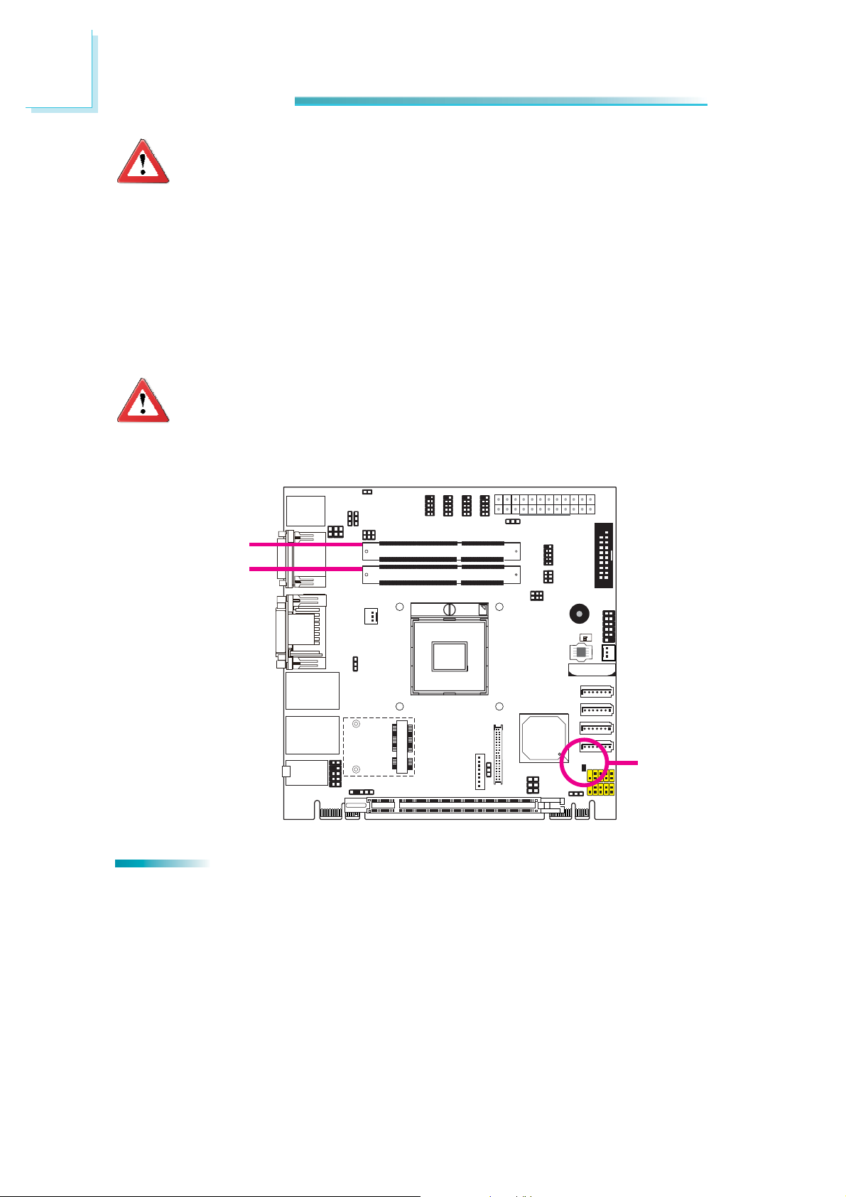
System Memory
Important:
When the Standby Power LED lit red, it indicates that there is power on
the system board. Power-off the PC then unplug the power cord prior to
installing any devices. Failure to do so will cause severe damage to the
motherboard and components.
DDR3-2
DDR3-1
Features
• Two 204-pin DDR3 SODIMM sockets
• Supports 1066/1333/1600MHz DDR3 SDRAM
Standby
Power LED
16
• Dual channel memory interface
• Supports maximum of 16GB system memory
Page 17
Hardware Installation
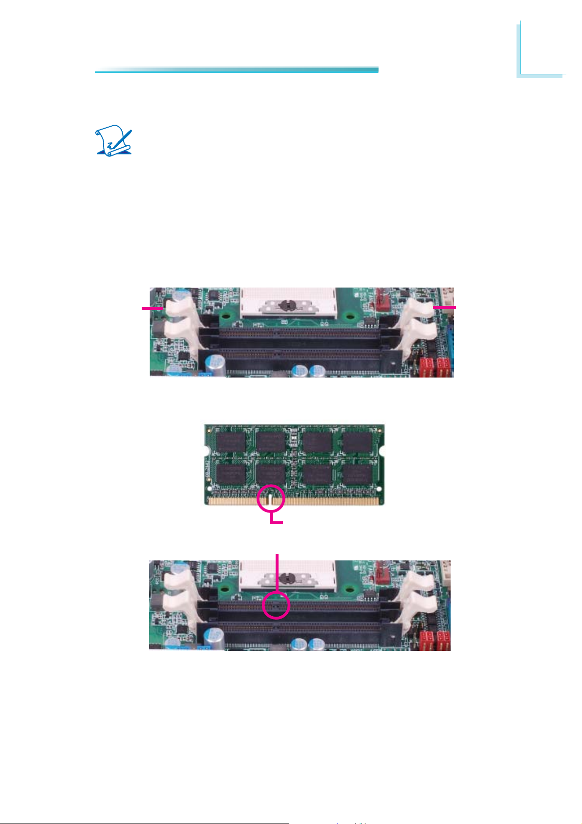
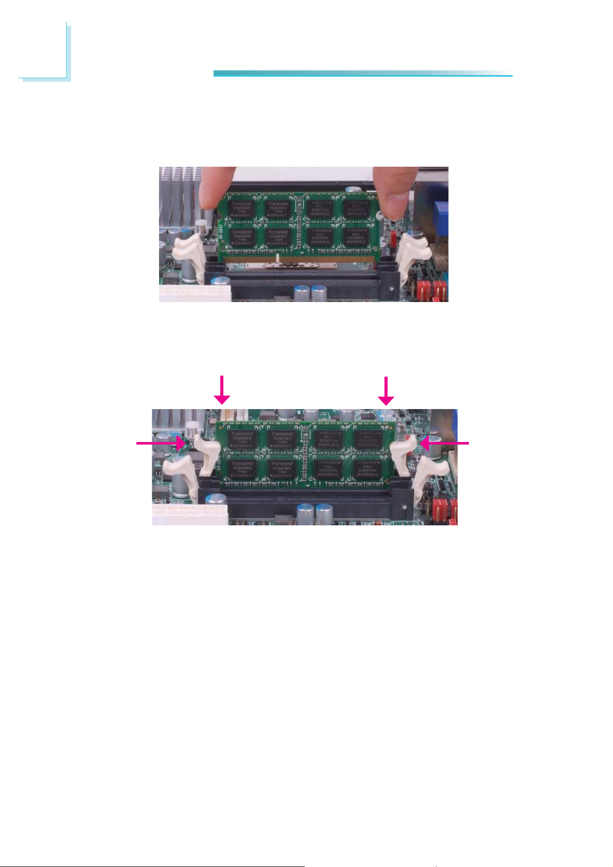
Installing the DIM Module
Note:
The system board used in the following illustrations may not resemble
the actual board. These illustrations are for reference only.
1. Make sure the PC and all other peripheral devices connected to it has been
powered down.
2. Disconnect all power cords and cables.
3. Locate the DIMM socket on the system board.
4. Push the “ejector tabs” which are at the ends of the socket to the side.
2
Ejector tab
5. Note how the module is keyed to the socket.
Notch
Key
Ejector tab
17
Page 18
2
Hardware Installation
6. Grasping the module by its edges, position the module above the socket with
the “notch” in the module aligned with the “key” on the socket. The keying
mechanism ensures the module can be plugged into the socket in only one
way.
7. Seat the module vertically, pressing it down fi rmly until it is completely seat-
ed in the socket. The ejector tabs at the ends of the socket will automatically
snap into the locked position to hold the module in place.
18
Page 19
Hardware Installation
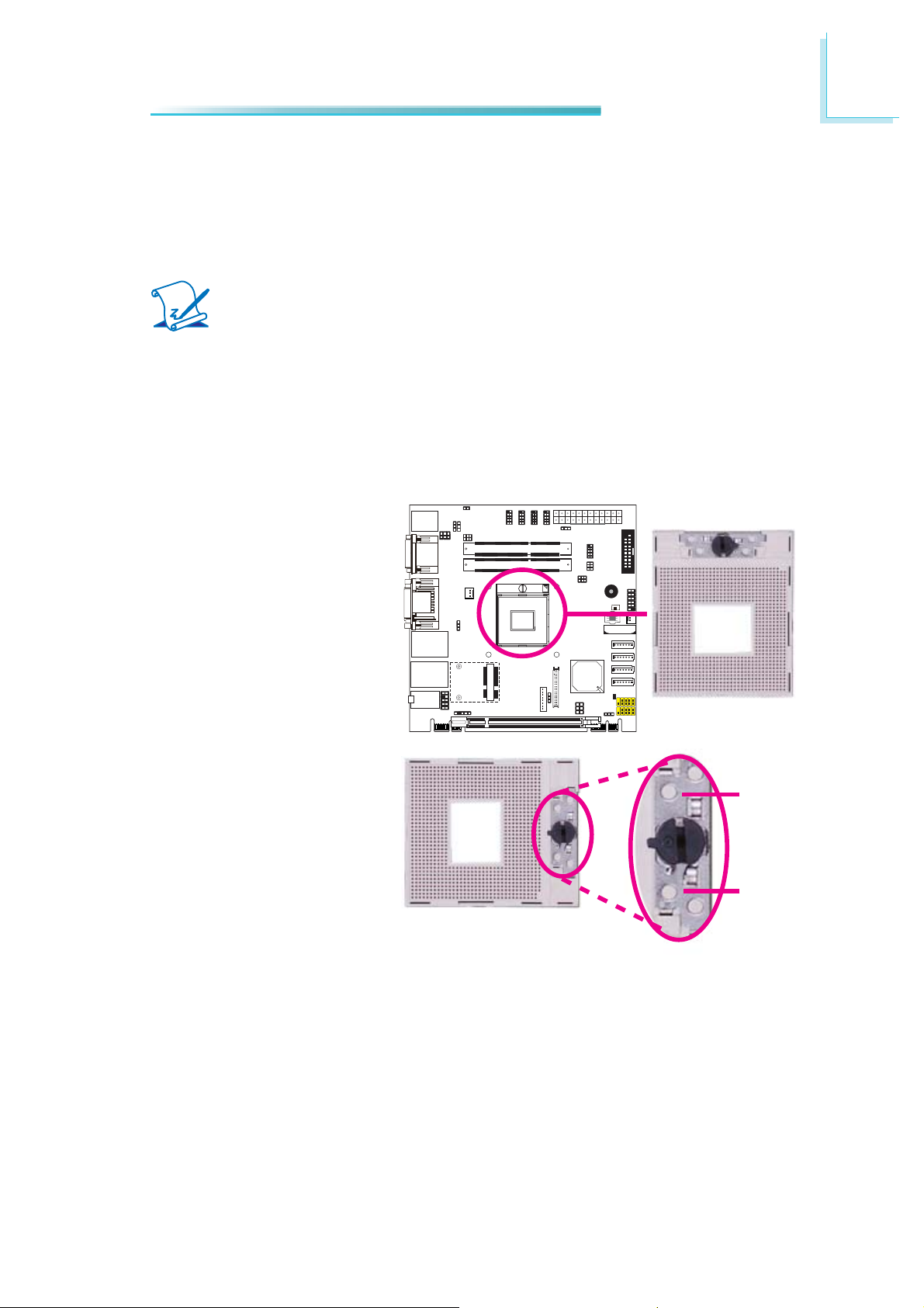
CPU
Overview
The system board is equipped with a surface mount PGA 988B CPU socket.
Note:
The system board used in the following illustrations may not resemble
the actual one. These illustrations are for reference only.
Installing the CPU
1. Make sure the PC and all other peripheral devices connected to it has been
powered down.
2. Disconnect all power cords and cables.
3. Locate the PGA 988B socket on the system board.
2
4. Make sure the screw is in
its unlock position. If it’s
not, use a screwdriver to
turn the screw to its unlock position.
Lock
Unlock
19
Page 20
2
Hardware Installation
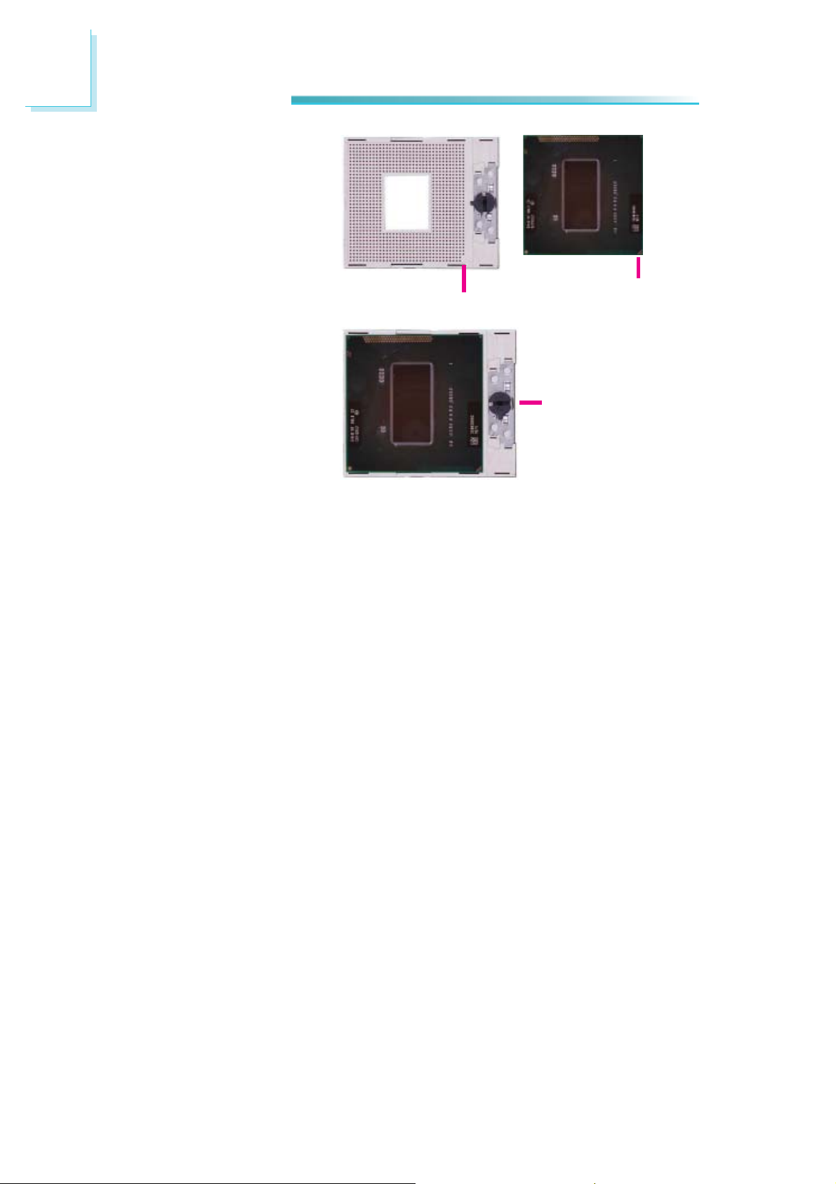
5. Position the CPU above the
socket. The gold triangular
mark on the CPU must
align with pin 1 of the CPU
socket.
Important:
Handle the CPU by its edges and avoid touching the
pins.
6. Insert the CPU into the
socket until it is seated
in place. The CPU will fi t
in only one orientation
and can easily be inserted
without exerting any force.
Use a screwdriver to turn
the screw to its lock position.
Gold triangular mark
Pin 1
Screw in locked
position
Important:
Do not force the CPU into
the socket. Forcing the
CPU into the socket may
bend the pins and damage
the CPU.
20
Page 21
Hardware Installation
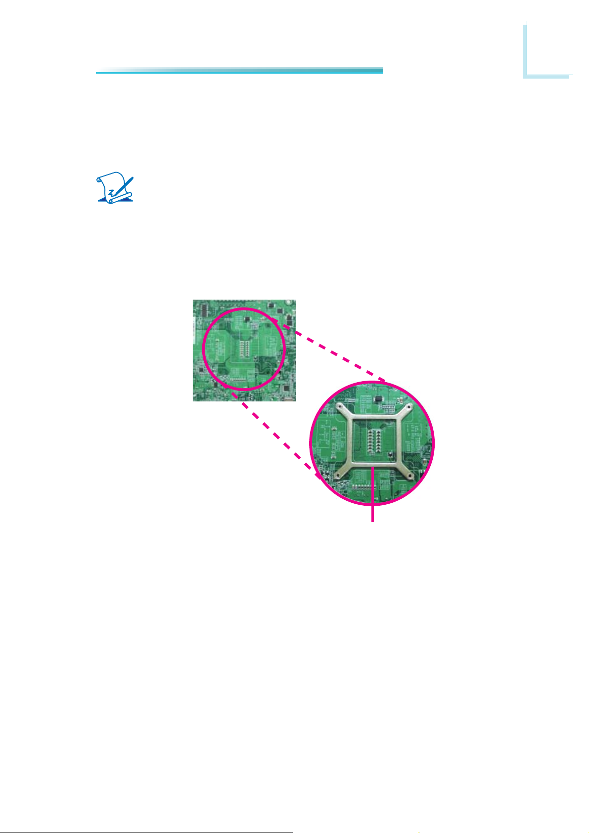
Installing the Fan and Heat Sink
The CPU must be kept cool by using a CPU fan with heat sink. Without suffi cient
air circulation across the CPU and heat sink, the CPU will overheat damaging
both the CPU and system board.
Note:
• Use only certifi ed fan and heat sink.
• Your fan and heat sink package usually contains the fan and heat sink
assembly, and an installation guide. If the installation procedure in the
installation guide differs from the one in this section, please follow the
installation guide in the package.
1. On the solder side of the board, match the retention module base to the
mounting holes around the CPU socket.
2
Retention module base
2. Turn to the component side of the board making sure the retention module
base is positioned and fi tted properly under the board.
3. Apply a thin layer of thermal paste on top of the CPU. Do not spread the
paste all over the surface. When you later place the heat sink on top, the
compound will disperse evenly.
21
Page 22
2
Hardware Installation
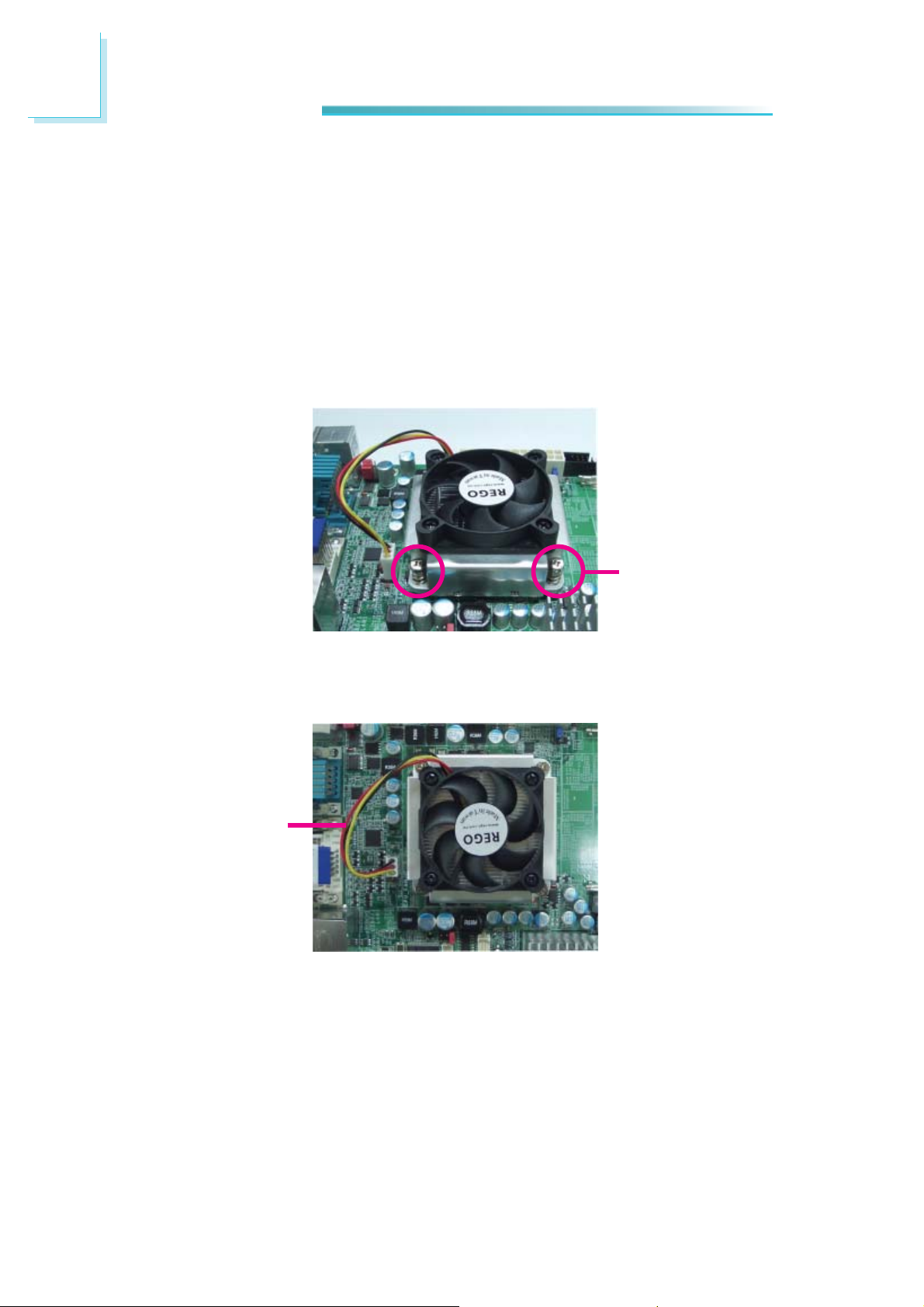
4. Place the fan / heat sink assembly on top of the CPU. The 4 screws around
the heat sink must match the screw holes of the retention module base. We
strongly recommend using this type of fan / heat sink assembly because it
provides adequate cooling to the components of the system board.
Turn each Phillips head screw half way down fi rst to initially stabilize the heat
sink onto the board, then fi nally tighten each screw.
Important:
Do not turn the fi rst screw all the way down followed by the next and so on.
This is to avoid imbalance which might cause cracks or fractures to the CPU
and/or heat sink assembly.
Mounting
screw
5. Connect the CPU fan’s cable connector to the CPU fan connector on the system board.
CPU fan cable
22
Page 23
Jumper Settings
Clear CMOS Data
2
Hardware Installation
JP10
1-2 On: Normal
(default)
If you encounter the following,
a) CMOS data becomes corrupted.
b) You forgot the supervisor or user password.
you can reconfi gure the system with the default values stored in the ROM BIOS.
To load the default values stored in the ROM BIOS, please follow the steps below.
1. Power-off the system and unplug the power cord.
2. Set JP10 pins 2 and 3 to On. Wait for a few seconds and set JP10 back to its
default setting, pins 1 and 2 On.
3. Now plug the power cord and power-on the system.
312
Clear CMOS Data
312
2-3 On:
23
Page 24
2
Hardware Installation
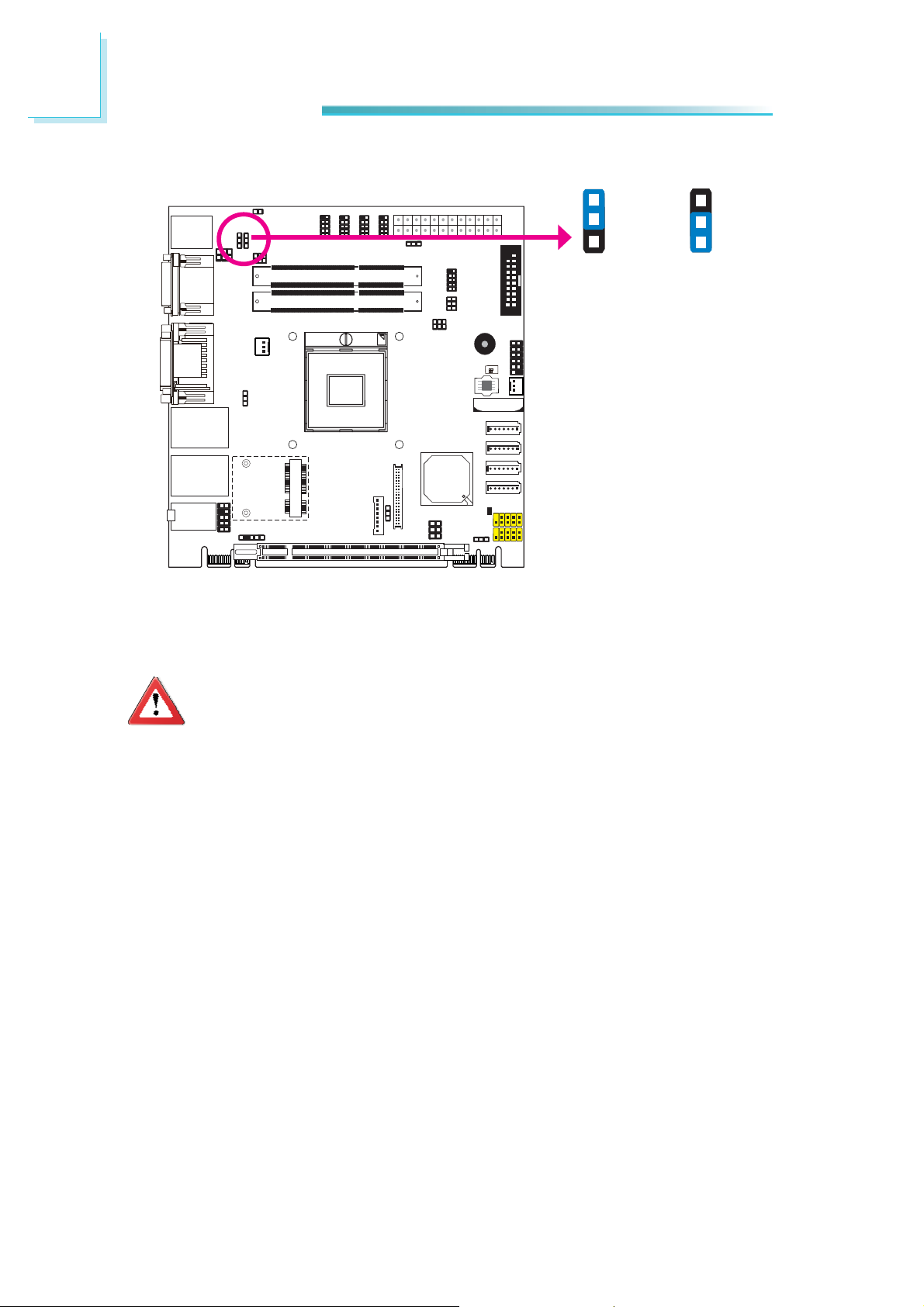
PS/2 Power Select
JP2
1-2 On: +5V
JP2 is used to select the power of the PS/2 keyboard and PS/2 mouse ports. Selecting +5V_standby will allow you to use the PS/2 keyboard or PS/2 mouse to
wake up the system.
1
2
3
(default)
+5V_standby
1
2
3
2-3 On:
Important:
The +5VSB power source of your power supply must support ≥720mA.
24
Page 25
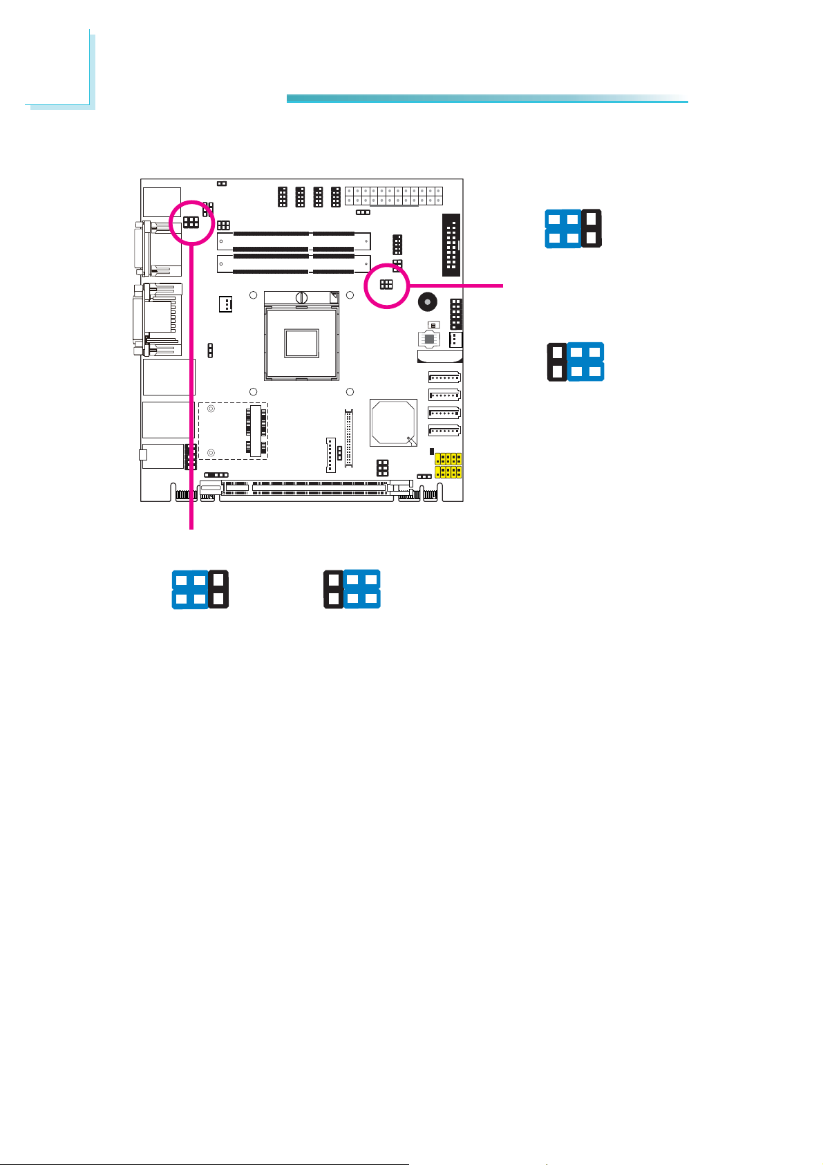
USB Power Select
2
Hardware Installation
USB 8-9
(JP8)
1-2 On: +5V
USB 0-1/2-3
(JP6)
1
2
3
(default)
3
2
1
1-2 On: +5V
(default)
1
2
3
2-3 On:
+5V_standby
3
2
1
2-3 On:
+5V_standby
This jumper is used to select the power of the USB ports. Selecting +5V_standby
will allow you to use a USB device to wake up the system.
Important:
If you are using the Wake-On-USB Keyboard/Mouse function for 2 USB
ports, the +5V_standby power source of your power supply must support ≥1.5A. For 3 or more USB ports, the +5V_standby power source of
your power supply must support ≥2A.
25
Page 26
2
Hardware Installation
Panel Power Select
JP9
1
3
5
1-2 On: +12V
JP9 is used to select the power supplied to the LCD panel.
Important:
Before powering-on the system, make sure JP9’s setting matches the
LCD panel’s specifi cation. Selecting the incorrect voltage will seriously
damage the LCD panel.
2
4
6
1
3
5
3-4 On: +5V
2
4
6
1
3
5
5-6 On: +3.3V
(default)
2
4
6
26
Page 27
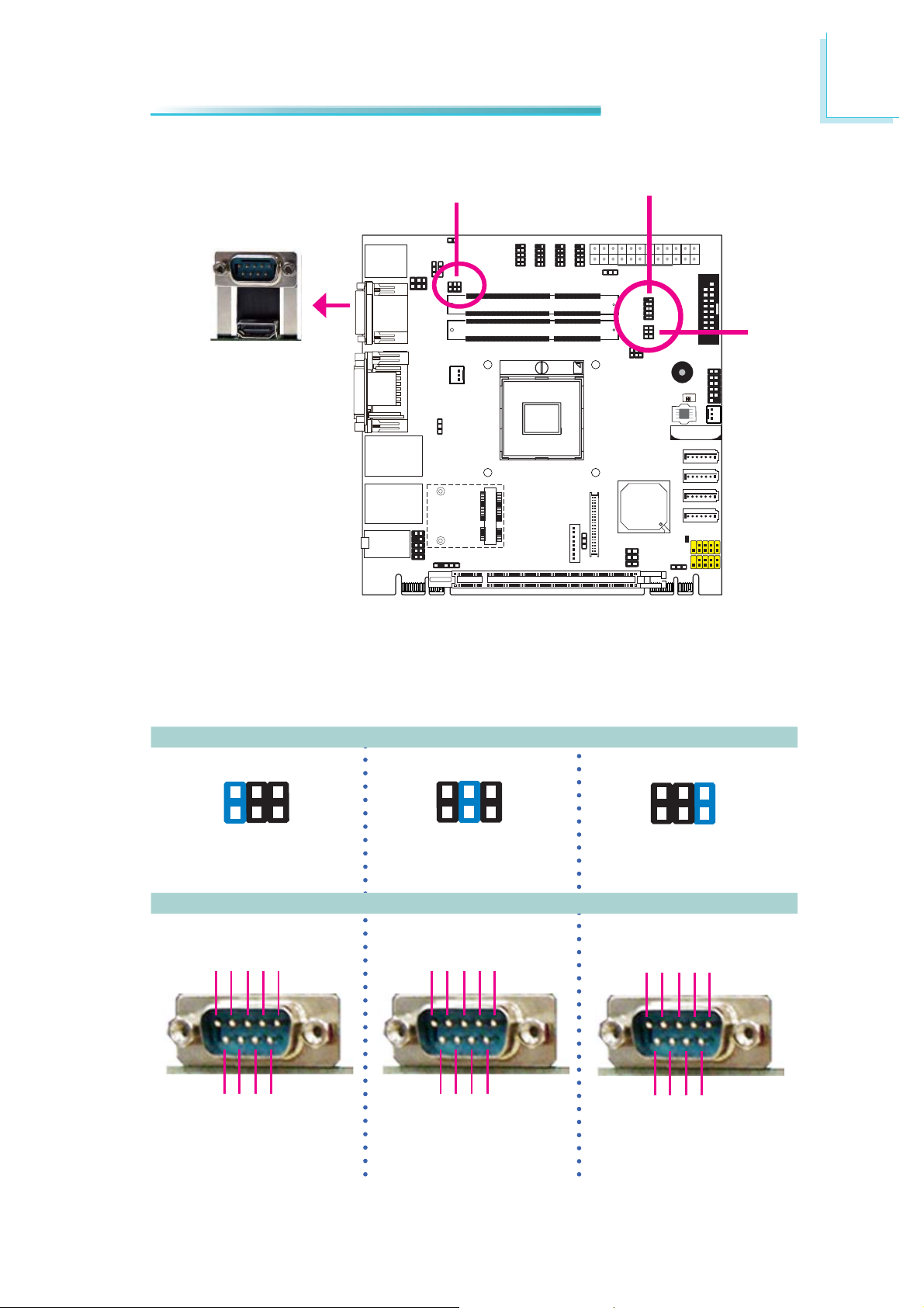
COM1/COM2 RS232/RS422/RS485 Select
JP4
COM 1
2
Hardware Installation
COM 2
JP5
JP4 (for COM1) and JP5 (for COM2) are used to confi gure the COM ports to
RS232, RS422 (Full Duplex) or RS485.
The pin function of the COM ports will vary according to the jumper’s setting.
JP4/JP5
64
2
531
1-2 On: RS232
(default)
DCD-TDRD
12345
DTR-
GND
3-4 On: RS422
Full Duplex
RXD+
12345
2
COM 1
TXD+
RXD-
64
531
TXD-
N.C.
64
2
531
5-6 On: RS485
DATA+
N.C.
DATA-
N.C.
N.C.
12345
6789
RI-
RTS-
CTS-
DSR-
RS232 RS422
6789
Full Duplex
N.C.
N.C.
N.C.
N.C.
6789
N.C.
N.C.
N.C.
RS485
N.C.
27
Page 28
2
Hardware Installation
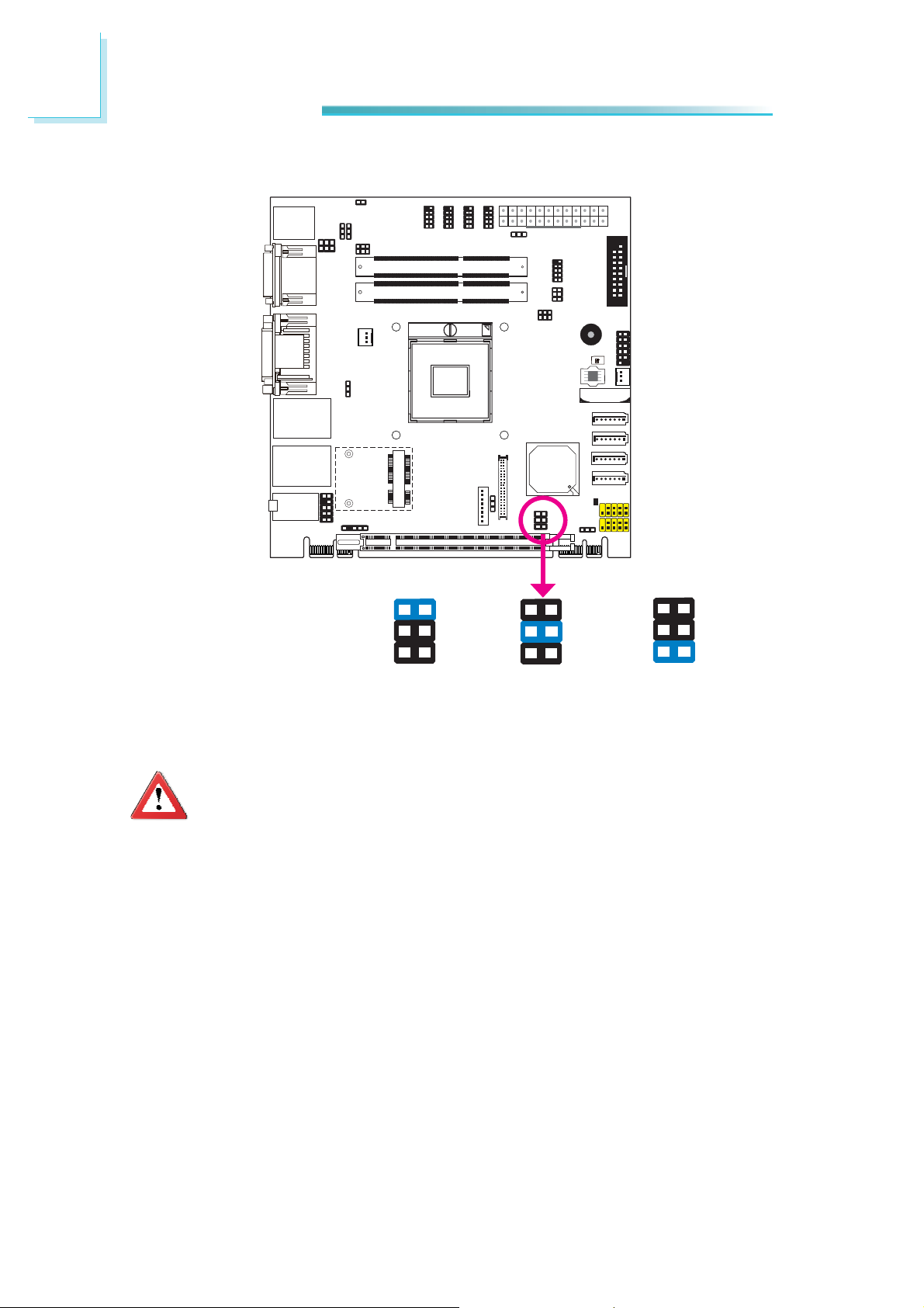
COM1/COM2 RS232/Power Select
2
4 6
13 5
JP3
1-3, 2-4 On: RS232
(default)
2 4 6
13 5
3-5 (+5V), 4-6 (+12V)
On: RS232 with power
JP1
2 4 6
1 3 5
1-3, 2-4 On: RS232
(default)
2 4 6
1 3 5
3-5 (+5V), 4-6 (+12V)
On: RS232 with power
28
Page 29
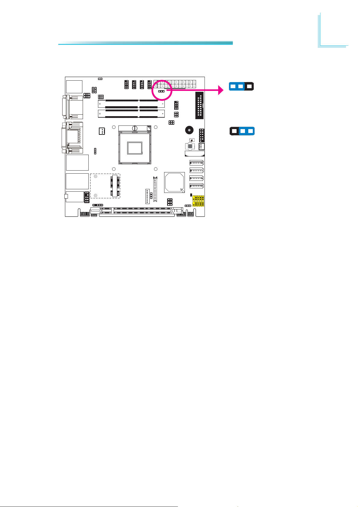
Power-on Select
2
Hardware Installation
To power-on via WOL after G3:
1. Set JP7 pins 2 and 3 to On.
JP7
312
1-2 On:
Power-on via power button
(default)
312
2-3 On:
Power-on via AC power; or
Power-on via WOL after G3
2. Set the “After G3” fi eld to Power Off/WOL.
3. Set the “GbE Wake Up From S5” to Enabled.
The BIOS fi elds are in the “South Bridge Confi guration” submenu (Chipset menu)
of the AMI BIOS utility.
To power-on via AC Power:
1. Set JP7 pins 2 and 3 to On.
2. Set the “After G3” fi eld to Power On.
29
Page 30
2
Hardware Installation
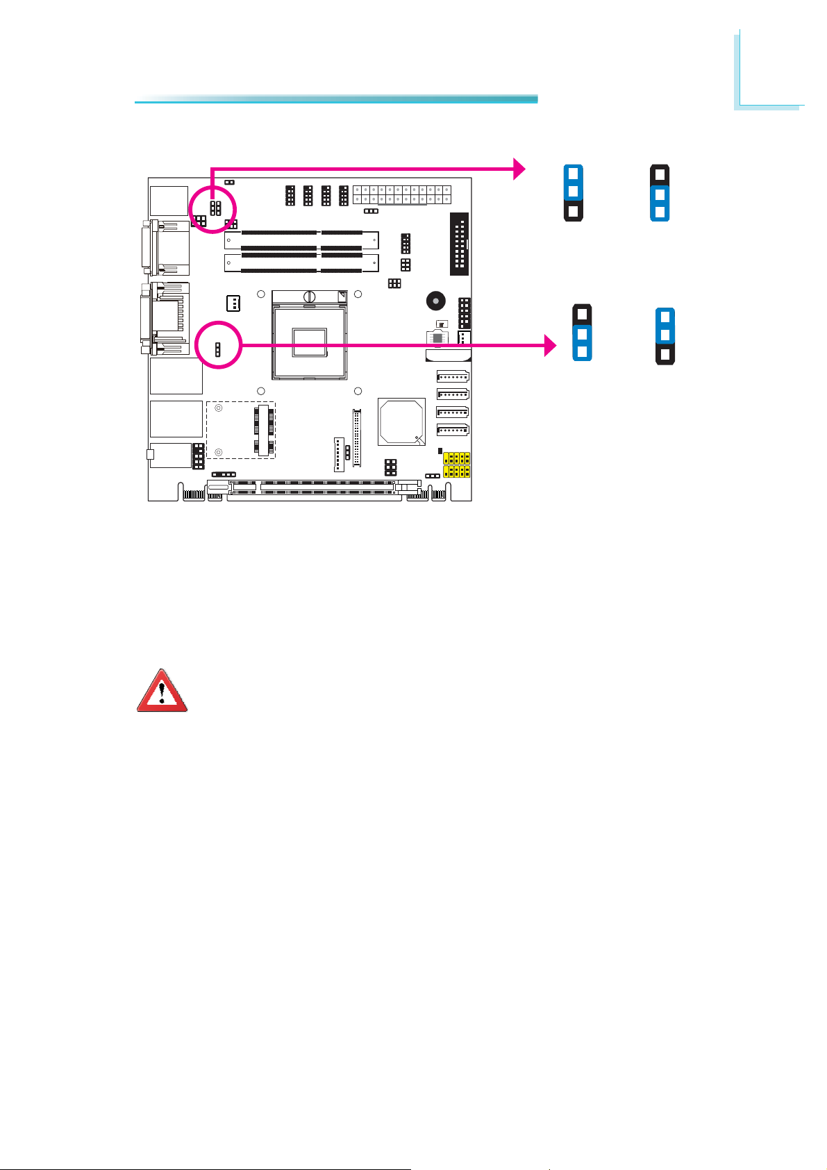
Backlight Level Select
3
2
1
1-2 On: +5V
(default)
JP 11
3
2
1
2-3 On: +3.3V
JP 11 is used to select the backlight level +5V or +3.3V.
30
Page 31

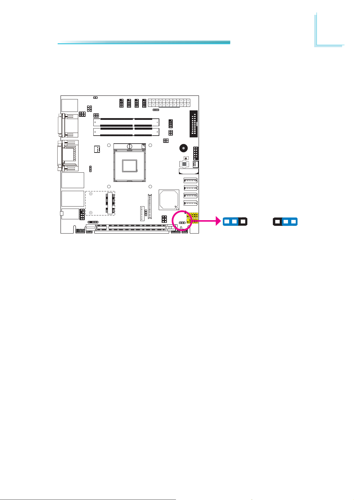
Switch
Hardware Installation
1
ON
2
2
SW1 is used to confi gure the PCIe x16 slot.
Note:
Confi gurations: supported only via a riser card.
One PCIe x16(default)
SW1
One PCIe x8, Two PCIe x4
1-2 Off:
1
ON
2
1 On, 2 Off:
Two PCIe x8
1
ON
2
1-2 On:
31
Page 32

2
Hardware Installation
Rear Panel I/O Ports
PS/2
K/B Mouse
USB 2.0
The rear panel I/O ports consist of the following:
• PS/2 mouse/keyboard port
• COM port
• DVI-I port
• DVI-I port (DVI-D signal only)
• 2 Intel LAN ports
• 6 USB ports
• Line-in jack
• Line-out jack
• Mic-in jack
COM 1
HDMI
(DVI-D signal only)
DVI-I
DVI-I
LAN 1
USB 3.0
LAN 2
USB 3.0
Line-in
Line-out
Mic-in
32
Page 33

PS/2 Keyboard/Mouse Port
PS/2
Keyboard/Mouse
2
Hardware Installation
These ports are used to connect a PS/2 mouse and a PS/2 keyboard. The PS/2
mouse port uses IRQ12.
Wake-On-PS/2 Keyboard/Mouse
The Wake-On-PS/2 Keyboard/Mouse function allows you to use the PS/2 keyboard or PS/2 mouse to power-on the system. To use this function:
• Jumper Setting
JP2 must be set to “2-3 On: +5V_standby”. Refer to “PS/2 Power Select” in
this chapter for more information.
• BIOS Setting
Confi gure the PS/2 keyboard/mouse wake up function in the Advanced menu
(“ACPI Power Management Confi guration” submenu) of the BIOS. Refer to
chapter 3 for more information.
Important:
The +5V_standby power source of your power supply must support
≥720mA.
33
Page 34

2
Hardware Installation
COM (Serial) Ports
COM 1
COM 1:
RS232/422/485
9
RI-
CTSDSR-
DTR-
RD
COM 3 to COM 6:
RS232
RTS-
GND
TD
DCD-
12
COM 5
COM 6
COM 4
COM 3
COM 2
9
RI-
COM 2:
RS232/422/485
COM 3 to COM 6 are fi xed at RS232.
The pin function of COM 1 and COM 2 ports will vary according to JP4/JP5’s setting. Refer to “COM1/COM2 RS232/RS422/RS485 Select” in this chapter for more
information.
The serial ports are asynchronous communication ports with 16C550A-compatible
UARTs that can be used with modems, serial printers, remote display terminals,
and other serial devices.
CTS-
DSR-
DTR-
RD
RTS-
GND
TD
DCD-
12
Connecting External Serial Ports
Your COM port may come mounted on a card-edge bracket. Install the card-edge
bracket to an available slot at the rear of the system chassis then insert the serial port cable to the COM connector. Make sure the colored stripe on the ribbon
cable is aligned with pin 1 of the COM connector.
34
BIOS Setting
Confi gure the serial ports in the Advanced menu (“Super IO Confi guration” sub-
menu) of the BIOS. Refer to chapter 3 for more information.
Page 35

Graphics Interface
The display ports consist of the following:
• HDMI
• DVI-I port
• DVI-I port (DVI-D signal only)
Note:
The 3rd Gen Intel Core processors support 3 independent displays. If
you are connecting 3 display devices, make sure 2 of the devices are
connected to the HDMI and DVI (-D signal) interfaces.
2
Hardware Installation
HDMI
(DVI-D signal only)
DVI-I
DVI-I
HDMI Port
The HDMI port which carries both digital audio and video signals is used to connect a LCD monitor or digital TV that has the HDMI port.
35
Page 36

2
Hardware Installation
DVI-I Port
The DVI-I port is used to connect an LCD monitor. This port supports DVI-D signal only.
Connect the display device’s cable connector to the DVI-I port. After you plug the
cable connector into the port, gently tighten the cable screws to hold the connector in place.
BIOS Setting
Confi gure the display device in the Chipset menu (“North Bridge Confi guration”
submenu) of the BIOS. Refer to chapter 3 for more information.
36
Page 37

RJ45 LAN Ports
LAN 2
2
Hardware Installation
LAN 1
Features
• Intel 82579LM with iAMT8.0 Gigabit LAN Phy
• Intel 82574L PCI Express Gigabit LAN controller
The LAN ports allow the system board to connect to a local area network by
means of a network hub.
BIOS Setting
Confi gure the onboard LAN in the Chipset menu (“South Bridge Confi guration”
submenu) of the BIOS. Refer to chapter 3 for more information.
Driver Installation
Install the LAN drivers. Refer to chapter 4 for more information.
37
Page 38

2
Hardware Installation
USB Ports
USB 9
USB 8
USB 2.0
USB 1
USB 0
USB 3.0
USB 3
USB 2
USB 3.0
GND
+Data
Key
9
10
N. C.
USB allows data exchange between your computer and a wide range of simultaneously accessible external Plug and Play peripherals.
The system board is equipped with four onboard USB 3.0/2.0/1.1 ports (USB
0-3) and two onboard USB 2.0/1.1 ports (USB 8-9). The two 10-pin connectors
allow you to connect 4 additional USB 2.0/1.1 ports (USB 4-7). The additional
USB ports may be mounted on a card-edge bracket. Install the card-edge bracket
to an available slot at the rear of the system chassis and then insert the USB
port cables to a connector.
GND
+Data
-Data
VCC
VCC
-Data
1
2
USB 6-7
USB 4-5
USB 2.0
BIOS Setting
38
Confi gure the onboard USB in the Advanced menu (“USB Confi guration” sub-
menu) of the BIOS. Refer to chapter 3 for more information.
Driver Installation
You may need to install the proper drivers in your operating system to use the
USB device. Refer to your operating system’s manual or documentation for more
information.
Page 39

Hardware Installation
Wake-On-USB Keyboard/Mouse
The Wake-On-USB Keyboard/Mouse function allows you to use a USB keyboard or
USB mouse to wake up a system from the S3 (STR - Suspend To RAM) state. To
use this function:
• Jumper Setting
JP6 must be set to “2-3 On: +5V_standby”. Refer to “USB Power Select” in
this chapter for more information.
Important:
If you are using the Wake-On-USB Keyboard/Mouse function for 2 USB
ports, the +5V_standby power source of your power supply must support ≥1.5A. For 3 or more USB ports, the +5V_standby power source of
your power supply must support ≥2A.
2
39
Page 40

2
Hardware Installation
Audio
Rear audio
Line-in
Line-out
Mic-in
10
9
Line2-JD
Key
Mic2-JD
Presence Signal
GND
Line2-L
Front_IO_Sense
Line2-R
Mic2-R
Mic2-L
1
2
Front
audio
Rear Audio
The system board is equipped with 3 audio jacks. A jack is a one-hole connecting
interface for inserting a plug.
• Mic-in Jack (Pink)
This jack is used to connect an external microphone.
• Line-in Jack (Light Blue)
This jack is used to connect any audio devices such as Hi-fi set, CD player,
tape player, AM/FM radio tuner, synthesizer, etc.
• Line-out Jack (Lime)
This jack is used to connect a headphone or external speakers.
Front Audio
The front audio connector allows you to connect to the second line-out and micin jacks that are at the front panel of your system.
40
Page 41

Hardware Installation
BIOS Setting
Confi gure the onboard audio in the Chipset menu (“South Bridge” submenu) of
the BIOS. Refer to chapter 3 for more information.
Driver Installation
Install the audio driver. Refer to chapter 4 for more information.
2
41
Page 42

2
Hardware Installation
I/O Connectors
S/PDIF Connector
SPDIF out
Key
Ground
+5V
SPDIF in
15
The S/PDIF connector is used to connect an external S/PDIF port. Your S/PDIF
port may be mounted on a card-edge bracket. Install the card-edge bracket to
an available slot at the rear of the system chassis then connect the audio cable
to the S/PDIF connector. Make sure pin 1 of the audio cable is aligned with pin 1
of the S/PDIF connector.
42
Page 43

LVDS LCD Panel Connector
LCD/Inverter Power Connector
2
Hardware Installation
8
21
1
LCD/Inverter
power
40 39
LVDS LCD
panel
The system board allows you to connect a LCD Display Panel by means of the
LVDS LCD panel connector and the LCD/Inverter power connector. These connectors transmit video signals and power from the system board to the LCD Display
Panel.
Refer to the next page for the pin functions of these connectors.
BIOS Setting
Confi gure the LCD panel in the Advanced Chipset Features submenu of the BIOS.
Refer to chapter 3 for more information.
43
Page 44

2
Hardware Installation
LVDS LCD Panel Connector
Pins
1
3
5
7
9
11
13
15
17
19
21
23
25
27
29
31
33
35
37
39
Function
GND
LVDS_Out3+
LVDS_Out3-
GND
LVDS_Out2+
LVDS_Out2-
GND
LVDS_Out1+
LVDS_Out1-
GND
LVDS_Out0+
LVDS_Out0-
GND
LVDS_CLK1+
LVDS_CLK1-
GND
LVDS_DDCCLK
LVDS_DDCDAA
Panel Power
Panel Power
Pins
2
4
6
8
10
12
14
16
18
20
22
24
26
28
30
32
34
36
38
40
Function
GND
LVDS_Out7+
LVDS_Out7-
GND
LVDS_Out6+
LVDS_Out6-
GND
LVDS_Out5+
LVDS_Out5-
GND
LVDS_Out4+
LVDS_Out4-
GND
LVDS_CLK2+
LVDS_CLK2-
GND
N. C.
N. C.
Panel Power
Panel Power
LCD/Inverter Power Connector
Pins
Function
1
GND
2
GND
3
Panel Inverter Brightness Voltage Control
4
Panel Power
5
+3.3V
6
Panel Backlight On/Off Control
7
+12V
8
+12V
44
Page 45

Digital I/O Connectors
2
Hardware Installation
19
21
The 8-bit Digital I/O connector provides powering-on function to external devices
that are connected to these connectors.
Pin Pin Assignment Pin Pin Assignment
1 GND 2 +12V
3 DIO7 4 +12V
5 DIO6 6 GND
7 DIO5 8 VCC
9 DIO4 10 VCC
11 DIO3 12 GND
13 DIO2 14 V_5P0_STBY
15 DIO1 16 V_5P0_STBY
17 DIO0 18 GND
19 GND
45
Page 46

2
Hardware Installation
SATA (Serial ATA) Connectors
7
RXP
GND
SATA 3.0 6Gb/s
SATA 2.0 3Gb/s
Features
• 4 Serial ATA ports
- 2 SATA2 ports with data transfer rate up to 3Gb/s
- 2 SATA3 ports with data transfer rate up to 6Gb/s
• Integrated Advanced Host Controller Interface (AHCI) controller
RXN
GND
TXP
TXN
GND
SATA 0
SATA 1
SATA 4
SATA 5
1
• Supports RAID 0, RAID 1, RAID 5 and RAID 10
The Serial ATA connectors are used to connect Serial ATA devices. Connect one
end of the Serial ATA cable to a SATA connector and the other end to your Serial
ATA device.
BIOS Setting
Confi gure the Serial ATA drives in the Advanced menu (“IDE Confi guration” sub-
menu) of the BIOS. Refer to chapter 3 for more information.
46
Page 47

Cooling Fan Connectors
2
Hardware Installation
3
1
CPU fan
1
3
System fan
The fan connectors are used to connect cooling fans. The cooling fans will provide
adequate airfl ow throughout the chassis to prevent overheating the CPU and sys-
tem board components.
Sense
Power
Ground
Ground
Power
Sense
BIOS Setting
The Advanced menu (“Hardware Health Confi guration” submenu) of the BIOS will
display the current speed of the cooling fans. Refer to chapter 3 for more information.
47
Page 48

2
Hardware Installation
Chassis Intrusion Connector
1
2
Signal
Ground
The board supports the chassis intrusion detection function. Connect the chassis intrusion sensor cable from the chassis to this connector. When the system’s
power is on and a chassis intrusion occurred, an alarm will sound. When the
system’s power is off and a chassis intrusion occurred, the alarm will sound only
when the system restarts.
MyGuard Hardware Monitor
Install the “MyGuard Hardware Monitor” utility. By default, the chassis intrusion
detection function is disabled. When enabled, a warning message will appear
when the chassis is open. The utility can also be confi gured so that a beeping
alarm will sound when the chassis is open. Refer to the “MyGuard Hardware
Monitor” section in chapter 4 for more information.
48
Page 49

Power Connectors
2
Hardware Installation
COM
COM
+3.3VDC
+3.3VDC
1
13
COM
-12VDC
+3.3VDC
Use a power supply that complies with the ATX12V Power Supply Design Guide
Version 1.1. An ATX12V power supply unit has a standard 24-pin ATX main power connector that must be inserted into the 24-pin connector.
The power connector from the power supply unit are designed to fi t the 24-pin
connector in only one orientation. Make sure to fi nd the proper orientation before
plugging the connectors.
The system board requires a minimum of 300 Watt power supply to operate. Your
system confi guration (CPU power, amount of memory, add-in cards, peripherals,
etc.) may exceed the minimum power requirement. To ensure that adequate
power is provided, we strongly recommend that you use a minimum of 400 Watt
(or greater) power supply.
Important:
Insuffi cient power supplied to the system may result in instability or
the add-in boards and peripherals not functioning properly. Calculating
the system’s approximate power usage is important to ensure that the
power supply meets the system’s consumption requirements.
+5VDC
+5VDC
COM
COM
PS_ON#
PWR_OK
COM
NC
COM
+5VSB
+5VDC
+5VDC
+12VDC
12
24
COM
+5VDC
+3.3VDC
+12VDC
49
Page 50

2
Hardware Installation
Standby Power LED
Standby
Power LED
This LED will lit red when the system is in the standby mode. It indicates that
there is power on the system board. Power-off the PC and then unplug the power
cord prior to installing any devices. Failure to do so will cause severe damage to
the motherboard and components.
50
Page 51

Front Panel Connectors
2
Hardware Installation
21
HDD-LED
RESET-SW
HDD-LED - HDD LED
This LED will light when the hard drive is being accessed.
RESET SW - Reset Switch
11
PWR-LED
PWR-BTN
12
This switch allows you to reboot without having to power off the system.
PWR-BTN - Power Switch
This switch is used to power on or off the system.
PWR-LED - Power/Standby LED
When the system’s power is on, this LED will light. When the system is in the S1
(POS - Power On Suspend) state, it will blink every second. When the system is
in the S3 (STR - Suspend To RAM) state, it will blink every 4 seconds.
Pin Pin Assignment Pin Pin Assignment
HDD-LED
RESET SW 7 Ground 6 Signal
3 HDD Power PWR-LED 2 LED Power
5 Signal 4 LED Power
9 RST Signal
11 N.C. 10 Signal
PWR-BTN 8 Ground
51
Page 52

2
Hardware Installation
Expansion Slots
Mini PCI Express
PCI Express x16
PCIE 2 PCIE 3
PCI Express x1
PCI Express x16 Slot
Install PCI Express x16 graphics card, that comply to the PCI Express specifi ca-
tions, into the PCI Express x16 slot. To install a graphics card into the x16 slot,
align the graphics card above the slot then press it down fi rmly until it is com-
pletely seated in the slot. The retaining clip of the slot will automatically hold the
graphics card in place.
PCI Express x1
Two PCIe x1 gold fi ngers for customized expansion (PCI or Mini PCIe) via a riser
card.
Mini PCIe Slot
The Mini PCIe socket is used to install a Mini PCIe card. Mini PCIe card is a small
form factor PCI card with the same signal protocol, electrical defi nitions, and con-
fi guration defi nitions as the conventional PCI.
52
Page 53

Hardware Installation
PCIE 2
A1 GND B1 +12V
A2 +12V B2 +12V
A3 +12V B3 +12V
A4 GND B4 GND
A5 +5V B5 SMB_CLK
A6 +5V B6 SMB_DATA
A7 +5V B7 GND
A8 +5V B8 +3V3
A9 +3V3 B9 NC
A10 +3V3 B10 +3VDU
A11 RESET B11 PCIE_WAKE
2
A12 GND B12 PME
A13 CLK+ B13 GND
A14 CLK- B14 TX+
A15 GND B15 TX-
A16 RX+ B16 GND
A17 RX- B17 PCIECLKRQ
A18 GND B18 GND
53
Page 54

2
Hardware Installation
PCIE 3
A1 GND B1 +12V
A2 +12V B2 +12V
A3 +12V B3 +12V
A4 GND B4 GND
A5 USB+ B5 SMB_CLK
A6 USB- B6 SMB_DATA
A7 +5V B7 GND
A8 +5V B8 +3V3
A9 +3V3 B9 NC
A10 +3V3 B10 +3VDU
A11 RESET B11 PCIE_WAKE
A12 GND B12 NC
A13 CLK+ B13 GND
A14 CLK- B14 TX+
A15 GND B15 TX-
A16 RX+ B16 GND
A17 RX- B17 PCIECLKRQ
A18 GND B18 GND
54
Page 55

Battery
2
Hardware Installation
Battery
The lithium ion battery powers the real-time clock and CMOS memory. It is an
auxiliary source of power when the main power is shut off.
Safety Measures
• Danger of explosion if battery incorrectly replaced.
• Replace only with the same or equivalent type recommend by the manufacturer.
• Dispose of used batteries according to local ordinance.
55
Page 56

3
BIOS Setup
Chapter 3 - BIOS Setup
Overview
The BIOS is a program that takes care of the basic level of communication between the CPU and peripherals. It contains codes for various advanced features
found in this system board. The BIOS allows you to confi gure the system and
save the confi guration in a battery-backed CMOS so that the data retains even
when the power is off. In general, the information stored in the CMOS RAM of
the EEPROM will stay unchanged unless a confi guration change has been made
such as a hard drive replaced or a device added.
It is possible that the CMOS battery will fail causing CMOS data loss. If this happens, you need to install a new CMOS battery and reconfi gure the BIOS settings.
Note:
The BIOS is constantly updated to improve the performance of the system board; therefore the BIOS screens in this chapter may not appear
the same as the actual one. These screens are for reference purpose
only.
Default Configuration
Most of the confi guration settings are either predefi ned according to the Load Op-
timal Defaults settings which are stored in the BIOS or are automatically detected
and confi gured without requiring any actions. There are a few settings that you
may need to change depending on your system confi guration.
Entering the BIOS Setup Utility
The BIOS Setup Utility can only be operated from the keyboard and all commands are keyboard commands. The commands are available at the right side of
each setup screen.
The BIOS Setup Utility does not require an operating system to run. After you
power up the system, the BIOS message appears on the screen and the memory
count begins. After the memory test, the message “Press DEL to run setup” will
appear on the screen. If the message disappears before you respond, restart the
system or press the “Reset” button. You may also restart the system by pressing
the <Ctrl> <Alt> and <Del> keys simultaneously.
56
Page 57

Legends
BIOS Setup
3
Keys
Right and Left arrows
Up and Down arrows
<Esc>
+ (plus key)
- (minus key)
Tab
<F1>
<Enter>
Function
Moves the highlight left or right to
select a menu.
Moves the highlight up or down
between submenus or fi elds.
Exits to the BIOS Setup Utility.
Scrolls forward through the values
or options of the highlighted fi eld.
Scrolls backward through the values
or options of the highlighted fi eld.
Selects a fi eld.
Displays General Help.
Press <Enter> to enter the high-
lighted submenu.
Scroll Bar
When a scroll bar appears to the right of the setup screen, it indicates that there
are more available fi elds not shown on the screen. Use the up and down arrow
keys to scroll through all the available fi elds.
Submenu
When ““ appears on the left of a particular fi eld, it indicates that a submenu
which contains additional options are available for that fi eld. To display the sub-
menu, move the highlight to that fi eld and press <Enter>.
57
Page 58

3
BIOS Setup
AMI BIOS Setup Utility
Main
The Main menu is the fi rst screen that you will see when you enter the BIOS
Setup Utility.
Aptio Setup Utility - Copyright (C) 2011 American Megatrends, Inc.
Main
Advanced
Boot Security
Save & ExitChipset
BIOS Information
BIOS Vendor
Core Version
Compliency
Project Version
Build Date and Time
System Language
System Date
System Time
Access Level
Version 2.14.1219. Copyright (C) 2011 American Megatrends, Inc.
System Date
The date format is <day>, <month>, <date>, <year>. Day displays a day, from
Sunday to Saturday. Month displays the month, from January to December. Date
displays the date, from 1 to 31. Year displays the year, from 1980 to 2099.
American Megatrends
4.6.5.1
UEFI 2.1; PI 1.2
1APTJ 0.15 x64
02/01/2012 10:37:24
[English]
[Wed 02/01/2012]
[23:12:27]
Administrator
Set the Date. Use Tab to
switch between Data
elements.
Select Screen
Select Item
Enter: Select
+/-: Change Opt.
F1: General Help
F2: Previous Values
F3: Optimized Defaults
ESC: Exit
58
System Time
The time format is <hour>, <minute>, <second>. The time is based on the 24hour military-time clock. For example, 1 p.m. is 13:00:00. Hour displays hours
from 00 to 23. Minute displays minutes from 00 to 59. Second displays seconds
from 00 to 59.
Page 59

BIOS Setup
Advanced
The Advanced menu allows you to confi gure your system for basic operation.
Some entries are defaults required by the system board, while others, if enabled,
will improve the performance of your system or let you set some features according to your preference.
Important:
Setting incorrect fi eld values may cause the system to malfunction.
Aptio Setup Utility - Copyright (C) 2011 American Megatrends, Inc.
Main
DDR3 Type Select
ACPI Power Management Confi guration
Trusted Computing
PC Health Status
CPU Confi guration
SATA Confi guration
Intel TXT(LT) Confi guration
PCH-FW Confi guration
Intel(R) Anti-Theft Technology Confi guration
AMT Confi guration
USB Confi guration
F81217 Second Super IO Confi guration
F71879 Super IO Confi guration
Serial Port Console Redirection
CPU PPM Confi guration
Advanced
[DDR3]
DDR3 Type Select
DDR3L
DDR3
Save & ExitChipset Boot Security
Set digital IO port as Input
or Output (601)
Select Screen
Select Item
Enter: Select
+/-: Change Opt.
F1: General Help
F2: Previous Values
F3: Optimized Defaults
ESC: Exit
3
Version 2.14.1219. Copyright (C) 2011 American Megatrends, Inc.
59
Page 60

3
BIOS Setup
ACPI Power Management Confi guration
This section is used to confi gure the ACPI Power Management.
Aptio Setup Utility - Copyright (C) 2011 American Megatrends, Inc.
Advanced
ACPI Power Management Confi guration
Enable ACPI Auto Confi guration
ACPI Sleep State
Resume by PME
Resume by RTC Alarm
Version 2.14.1219. Copyright (C) 2011 American Megatrends, Inc.
ACPI Sleep State
Selects the highest ACPI sleep state the system will enter when the Suspend
button is pressed.
[Disable]
[S3 (Suspend to RAM) ]
[Disabled]
[Disabled]
Enables or Disables BIOS
ACPI Auto Confi guration.
Select Screen
Select Item
Enter: Select
+/-: Change Opt.
F1: General Help
F2: Previous Values
F3: Optimized Defaults
ESC: Exit
S1(POS) Enables the Power On Suspend function.
S3(STR) Enables the Suspend to RAM function.
Resume by PME
Enable this fi eld to use the PME signal to wake up the system.
Resume by RTC Alarm
When Enabled, the system uses the RTC to generate a wakeup event.
60
Page 61

BIOS Setup
Trusted Computing (optional)
This section confi gures settings relevant to Trusted Computing innovations.
Aptio Setup Utility - Copyright (C) 2011 American Megatrends, Inc.
Advanced
3
Confi guration
TPM Support
Current Status Information
Version 2.14.1219. Copyright (C) 2011 American Megatrends, Inc.
TPM Support
Enables or Disables TPM. O.S. will not show TPM. Resetting the platform is
required.
[Disabled]
Enables or Disables
BIOS support for security
device. O.S. will not show
Security Device. TCG
EFI protocol and INT1A
interface will not be
available.
Select Screen
Select Item
Enter: Select
+/-: Change Opt.
F1: General Help
F2: Previous Values
F3: Optimized Defaults
ESC: Exit
61
Page 62

3
BIOS Setup
PC Health Status
This section displays the SIO hardware health monitor.
Aptio Setup Utility - Copyright (C) 2011 American Megatrends, Inc.
Advanced
Smart Fan Function
Case Open Beep
CPU Temperature
System Temperature
CPU FAN Speed
System FAN Speed
VCore
1V05
DDR
+3.3V
+5.0V
+12V
Version 2.14.1219. Copyright (C) 2011 American Megatrends, Inc.
Smart Fan Function
Aptio Setup Utility - Copyright (C) 2011 American Megatrends, Inc.
Advanced
Smart Fan Function
CPU Smart Fan Control
Boundary 1
Boundary 2
Boundary 3
Boundary 4
Speed Count 1
Speed Count 2
Speed Count 3
Speed Count 4
Speed Count 5
[Disabled]
: +39 C
: +37 C
: 2555 RPM
: N/A
: +0.872V
: +1.05V
: +1.536V
: +3.248 V
: +4.912 V
: +12.144 V
[Automatic]
70
60
50
40
100
75
50
25
10
Smart Fan Function
Select Screen
Select Item
Enter: Select
+/-: Change Opt.
F1: General Help
F2: Previous Values
F3: Optimized Defaults
ESC: Exit
Enable CPU SmartFan
Select Screen
Select Item
Enter: Select
+/-: Change Opt.
F1: General Help
F2: Previous Values
F3: Optimized Defaults
ESC: Exit
62
Version 2.14.1219. Copyright (C) 2011 American Megatrends, Inc.
CPU Smart Fan Control
When this feature is set to Automatic, the CPU’s fan speed will rotate according to the CPU’s temperature. The higher the temperature, the faster the
speed of rotation.
Page 63

BIOS Setup
Boundary 1 to Boundary 4
The range is from 0-127.
Speed Count 1 to Speed Count 5
The range is from 1-100.
Case Open Beep
Set this fi eld to Enabled to allow the system to alert you of a chassis intru-
sion event.
3
63
Page 64

3
BIOS Setup
CPU Confi guration
This section is used to confi gure the CPU. It will also display the detected CPU
information.
Aptio Setup Utility - Copyright (C) 2011 American Megatrends, Inc.
Advanced
CPU Confi guration
Intel (R) Core (TM) i7-3610QE CPU @ 2.30GHz
CPU Signature
Microcode Patch
Max CPU Speed
Min CPU Speed
CPU Speed
Processor Cores
Intel HT Technology
Intel VT-x Technology
Intel SMX Technology
64-bit
L1 Data Cache
L1 Code Cache
L2 Cache
L3 Cache
Hyper-threading
Active Processor Cores
Limit CPUID Maximum
Intel Virtualization Technology
306a8
7
2300 MHz
1200 MHz
2300 MHz
4
Supported
Supported
Supported
Supported
32 kB x 4
32 kB x 4
256kB x 4
6144 kB
[Enabled]
[All]
[Disabled]
[Disabled]
Enabled for Windows XP
and Linux (OS optimized
for Hyper-Threading
Technology) and Disabled
for other OS (OS not
optimized for
Hyper-Threading
Technology). When
Disabled only one thread
per enabled core is
enabled.
Select Screen
Select Item
Enter: Select
+/-: Change Opt.
F1: General Help
F2: Previous Values
F3: Optimized Defaults
ESC: Exit
Version 2.14.1219. Copyright (C) 2011 American Megatrends, Inc.
Hyper-threading
Enable this fi eld for Windows XP and Linux which are optimized for Hyper-
Threading technology. Select disabled for other OSes not optimized for HyperThreading technology. When disabled, only one thread per enabled core is
enabled.
Active Processor Cores
Number of cores to enable in each processor package.
Limit CPUID Maximum
The CPUID instruction of some newer CPUs will return a value greater than
3. The default is Disabled because this problem does not exist in the Windows series operating systems. If you are using an operating system other
than Windows, this problem may occur. To avoid this problem, enable this
fi eld to limit the return value to 3 or less than 3.
Intel Virtualization Technology
When this fi eld is set to Enabled, the VMM can utilize the additional hardware
capabilities provided by Vanderpool Technology.
64
Page 65

SATA Confi guration
This section is used to confi gure SATA functions.
Aptio Setup Utility - Copyright (C) 2011 American Megatrends, Inc.
Advanced
BIOS Setup
3
SATA Controller(s)
SATA Mode Selection
SATA Test Mode
Serial ATA Port 0
Software Preserve
Serial ATA Port 1
Software Preserve
Serial ATA Port 4
Software Preserve
Serial ATA Port 5
Software Preserve
Version 2.14.1219. Copyright (C) 2011 American Megatrends, Inc.
[Enabled]
[IDE]
[Enabled]
Hitachi HDT721 (1000.
Supported
Hitachi HDS722 (2000.
Supported
Empty
Unknown
ATAPI iHAS32 ATAPI
N/A
Enable or disable SATA
Device.
Select Screen
Select Item
Enter: Select
+/-: Change Opt.
F1: General Help
F2: Previous Values
F3: Optimized Defaults
ESC: Exit
SATA Controller(s)
This fi eld is used to enable or disable the Serial ATA channels.
SATA Mode Selection
IDE Mode
This option confi gures the Serial ATA drives as Parallel ATA storage devices.
AHCI Mode
This option allows the Serial ATA devices to use AHCI (Advanced Host Controller Interface).
RAID Mode
This option allows you to create RAID or Intel Matrix Storage confi guration on
Serial ATA devices.
SATA Test Mode
This fi eld is used to enable or disable the Serial ATA test mode.
65
Page 66

3
BIOS Setup
If AHCI or RAID is selected in the SATA Mode Selection, it will display the following information:
Aptio Setup Utility - Copyright (C) 2011 American Megatrends, Inc.
Advanced
SATA Controller(s)
SATA Mode Selection
SATA Test Mode
Agressive LPM Support
Software Feature Mask Confi guration
Serial ATA Port 0
Software Preserve
Port 0
Hot Plug
External SATA
SATA Device Type
Spin Up Device
Serial ATA Port 1
Software Preserve
Port 1
Hot Plug
External SATA
SATA Device Type
Spin Up Device
Serial ATA Port 4
Software Preserve
Port 4
Hot Plug
External SATA
Version 2.14.1219. Copyright (C) 2011 American Megatrends, Inc.
[Enabled]
[AHCI]
[Disabled]
[Enabled]
Hitachi HDT721 (1000.
Supported
[Enabled]
[Disabled]
[Disabled]
[Hard Disk Driver]
[Disabled]
Hitachi HDS 722 (2000.
Supported
[Enabled]
[Disabled]
[Disabled]
[Hard Disk Driver]
[Disabled]
Empty
Unknown
[Enabled]
[Disabled]
[Disabled]
Serial ATA Port 0 to Serial ATA Port 5
Determines how SATA
controller(s) operate.
Select Screen
Select Item
Enter: Select
+/-: Change Opt.
F1: General Help
F2: Previous Values
F3: Optimized Defaults
ESC: Exit
These fi elds are used to confi gure the connected SATA devices.
66
Page 67

Software Feature Mask Confi guration
Aptio Setup Utility - Copyright (C) 2011 American Megatrends, Inc.
Advanced
RAID0
RAID1
RAID10
RAID5
Intel Rapid Recovery Technology
OROM UI and BANNER
HDD Unlock
LED Locate
IRRT only on eSATA
Smart Response Technology
OROM UI Delay
Version 2.14.1219. Copyright (C) 2011 American Megatrends, Inc.
[Enabled]
[Enabled]
[Enabled]
[Enabled]
[Enabled]
[Enabled]
[Enabled]
[Enabled]
[Enabled]
[Enabled]
[2 Seconds]
BIOS Setup
3
Enable or disable RAID0
feature.
Select Screen
Select Item
Enter: Select
+/-: Change Opt.
F1: General Help
F2: Previous Values
F3: Optimized Defaults
ESC: Exit
RAID0 to RAID5
Enables or disables RAID0 to RAID5 feature.
Intel Rapid Recovery Technology
Enables or disables Intel Rapid Recovery Technology.
OROM UI and BANNER
When enabled, the OROM UI is shown. When disabled, no OROM banner or
information will be displayed if all disks and RAID volumes are Normal.
HDD Unlock
When enabled, it indicates that the HDD password unlock in the OS is enabled.
LED Locate
When enabled, it indicates that the LED/SGPIO hardware is attached and
ping to locate feature is enabled on the OS.
IRRT only on eSATA
When enabled, only IRRT volumes can span internal and eSATA drives.
When disabled, any RAID volume can span internal and eSATA drives.
67
Page 68

3
BIOS Setup
Smart Response Technology
Enables or disables Smart Response Technology.
OROM UI Delay
When enabled, it indicates the delay of the OROM UI Splash Screen in a normal status.
68
Page 69

BIOS Setup
Intel TXT (LT) Confi guration
This section is used to confi gure the Intel Trusted Execution technology.
Aptio Setup Utility - Copyright (C) 2011 American Megatrends, Inc.
Advanced
Intel Trusted Execution Technology Confi guration
Intel TXT support only can be enabled/disabled if SMX is
enabled. VT and VT-d support must also be enabled prior to TXT.
Secure Mode Extension (SMX)
Intel TXT(LT) Support
Enabled
[Disabled]
Select Screen
Select Item
Enter: Select
+/-: Change Opt.
F1: General Help
F2: Previous Values
F3: Optimized Defaults
ESC: Exit
3
Version 2.14.1219. Copyright (C) 2011 American Megatrends, Inc.
Secure Mode Extensions (SMX)
The options are Enabled and Disabled.
Intel TXT(LT) Support
The options are Enabled and Disabled.
PCH-FW Confi guration
Aptio Setup Utility - Copyright (C) 2011 American Megatrends, Inc.
Advanced
ME FW Version
ME Firmware Mode
ME Firmware Type
ME Firmware SKU
Firmware Update Confi guration
8.0.2.1410
Normal Mode
Full Sku Firmware
5MB
Select Screen
Select Item
Enter: Select
+/-: Change Opt.
F1: General Help
F2: Previous Values
F3: Optimized Defaults
ESC: Exit
Version 2.14.1219. Copyright (C) 2011 American Megatrends, Inc.
69
Page 70

3
BIOS Setup
Intel Anti-Theft Confi guration
This section is used to disable the PC at the hardware level in the event of loss
or theft.
Aptio Setup Utility - Copyright (C) 2011 American Megatrends, Inc.
Advanced
Intel Anti-Theft Technology Confi guration
Intel Anti-Theft Technology
Intel Anti-Theft Technology Recove
Enter Intel AT Suspend Mode
[Disabled]
3
[Disabled]
Enable/Disable Intel AT in
BIOS for testing only.
Select Screen
Select Item
Enter: Select
+/-: Change Opt.
F1: General Help
F2: Previous Values
F3: Optimized Defaults
ESC: Exit
Version 2.14.1219. Copyright (C) 2011 American Megatrends, Inc.
Intel Anti-Theft Technology
The options are Enabled and Disabled.
Enter Intel AT Suspend Mode
The options are Enabled and Disabled.
70
Page 71

Intel AMT Confi guration
Aptio Setup Utility - Copyright (C) 2011 American Megatrends, Inc.
Advanced
BIOS Setup
3
Intel AMT
Un-Confi gure ME
Version 2.14.1219. Copyright (C) 2011 American Megatrends, Inc.
Intel AMT
Enables or disables the AMT function.
Un-Confi gure ME
[Enabled]
[Disabled]
Enable/ Disable Intel
(R) Active Management
Technology BIOS
Extension. Note: iAMT
H/W is always enabled.
This option just controls
the BIOS extension
execution. If enabled,
this requires additional
fi rmware in the SPI
device.
Select Screen
Select Item
Enter: Select
+/-: Change Opt.
F1: General Help
F2: Previous Values
F3: Optimized Defaults
ESC: Exit
Select Enabled to unconfi gure the ME function without the need for a pass-
word.
71
Page 72

3
BIOS Setup
USB Confi guration
This section is used to confi gure USB.
Aptio Setup Utility - Copyright (C) 2011 American Megatrends, Inc.
Advanced
USB Confi guration
USB Devices:
2 Drivers, 1 Keyboard, 1 mouse, 2 Hubs
Legacy USB Support
EHCI Hand-off
USB hardware delays and time-outs:
USB transfer time-out
Device reset time-out
Device power-up delay
Mass Storage Devices:
Seagate FreeAgent GoFlex 214
TEAC USB UF000x 0.00
[Enabled]
[Disabled]
[20 sec]
[20 sec]
[Auto]
[Auto]
[Auto]
Enables Legacy USB
support. AUTO option
disables legacy support if
no USB devices are
connected. DISABLE
option will keep USB
devices available only for
EFI applications.
Select Screen
Select Item
Enter: Select
+/-: Change Opt.
F1: General Help
F2: Previous Values
F3: Optimized Defaults
ESC: Exit
Version 2.14.1219. Copyright (C) 2011 American Megatrends, Inc.
Legacy USB Support
Enabled
Enables legacy USB.
Auto
Disables support for legacy when no USB devices are connected.
Disabled
Keeps USB devices available only for EFI applications.
EHCI Hand-off
This is a workaround for OSes that does not support EHCI hand-off. The EHCI
ownership change should be claimed by the EHCI driver.
USB transfer time-out
The time-out value for Bulk and Interrupt transfers.
Device reset time-out
72
Selects the USB mass storage device start unit command timeout.
Page 73

BIOS Setup
Device power-up delay
Maximum time the device will take before it properly reports itself to the
Host Controller. “Auto” uses default value: for a Root port it is 100 ms, for a
Hub port the delay is taken from Hub descriptor.
3
73
Page 74

3
BIOS Setup
F81217 Second Super IO Confi guration
This section is used to confi gure the serial port functions.
Aptio Setup Utility - Copyright (C) 2011 American Megatrends, Inc.
Advanced
F81217 Second Super IO Confi guration
F81217 Second Super IO Chip
Serial Port 3 Confi guration
Serial Port 4 Confi guration
Serial Port 5 Confi guration
Serial Port 6 Confi guration
Version 2.14.1219. Copyright (C) 2011 American Megatrends, Inc.
F81217 Second IO
Set Parameters of Serial
Port 4 (COMB)
Select Screen
Select Item
Enter: Select
+/-: Change Opt.
F1: General Help
F2: Previous Values
F3: Optimized Defaults
ESC: Exit
Serial Port 3 Confi guration to Serial Port 6 Confi guration
Aptio Setup Utility - Copyright (C) 2011 American Megatrends, Inc.
Advanced
Serial Port 4 Confi guration
Serial Port
Device Settings
Change Settings
[Enabled]
IO=228h; IRQ=11;
[Auto]
Select an Optimal Setting
for Super IO device
74
Select Screen
Select Item
Enter: Select
+/-: Change Opt.
F1: General Help
F2: Previous Values
F3: Optimized Defaults
ESC: Exit
Version 2.14.1219. Copyright (C) 2011 American Megatrends, Inc.
Serial Port
Enables or disables the serial port.
Change Settings
Selects the IO/IRQ setting of the I/O device.
Page 75

BIOS Setup
F71879 Super IO Confi guration
This section is used to confi gure the I/O functions supported by the onboard
Super I/O chip.
Aptio Setup Utility - Copyright (C) 2011 American Megatrends, Inc.
Advanced
3
F71879 Super IO Confi guration
F71879 Super IO Chip
Restore AC Power Loss
Watchdog Timer
Super IO Watchingdog Timer
Serial Port 1 Confi guration
Serial Port 2 Confi guration
Version 2.14.1219. Copyright (C) 2011 American Megatrends, Inc.
Fintek F71879
[Power Off]
[Disabled]
10
Restore AC Power Loss
help.
Select Screen
Select Item
Enter: Select
+/-: Change Opt.
F1: General Help
F2: Previous Values
F3: Optimized Defaults
ESC: Exit
Restore AC Power Loss
Off
When power returns after an AC power failure, the system’s power is off. You
must press the Power button to power-on the system.
On
When power returns after an AC power failure, the system will automatically
power-on.
Last State
When power returns after an AC power failure, the system will return to the
state where you left off before power failure occurs. If the system’s power
is off when AC power failure occurs, it will remain off when power returns.
If the system’s power is on when AC power failure occurs, the system will
power-on when power returns.
Watchdog Timer
Enable or disable Super I/O watchdog timer.
75
Page 76

3
BIOS Setup
Serial Port 1 Confi guration to Serial Port 2 Confi guration
Aptio Setup Utility - Copyright (C) 2011 American Megatrends, Inc.
Advanced
Serial Port 1 Confi guration
Serial Port
Device Settings
Change Settings
Version 2.14.1219. Copyright (C) 2011 American Megatrends, Inc.
Aptio Setup Utility - Copyright (C) 2011 American Megatrends, Inc.
Advanced
Serial Port 2 Confi guration
Serial Port
Device Settings
Change Settings
Device Mode
[Enabled]
IO=3F8h; IRQ=4;
[Auto]
[Enabled]
IO=2F8h; IRQ=3;
[Auto]
[Serial Port Funct...]
Enable or Disable Serial
Port (COM)
Select Screen
Select Item
Enter: Select
+/-: Change Opt.
F1: General Help
F2: Previous Values
F3: Optimized Defaults
ESC: Exit
Enable or Disable Serial
Port (COM)
Version 2.14.1219. Copyright (C) 2011 American Megatrends, Inc.
Serial Port
Enables or disables the serial port.
Change Settings
Selects the IO/IRQ setting of the I/O device.
Device Mode
Enable or disable serial port (COM)
Select Screen
Select Item
Enter: Select
+/-: Change Opt.
F1: General Help
F2: Previous Values
F3: Optimized Defaults
ESC: Exit
76
Page 77

Serial Port Console Redirection
Aptio Setup Utility - Copyright (C) 2011 American Megatrends, Inc.
Advanced
BIOS Setup
3
COM1 (Disabled)
Console Redirection
COM2 (Pci Bus0, Dev0, Func0) (Disabled)
Console Redirection
Serial Port for Out-of-Band Management/
Windows Emergency Management Service (EMS)
Console Redirection
Console Redirection Settings
Version 2.14.1219. Copyright (C) 2011 American Megatrends, Inc.
Console Redirection Settings
The settings specify how the host computer and the remote computer (which
the user is using) will exchange data. Both computers should have the same
or the compatible settings.
Port is Disabled
Port is Disabled
[Disabled]
Console Redirection Enable or Disable.
Select Screen
Select Item
Enter: Select
+/-: Change Opt.
F1: General Help
F2: Previous Values
F3: Optimized Defaults
ESC: Exit
77
Page 78

3
BIOS Setup
CPU PPM Confi guration
Aptio Setup Utility - Copyright (C) 2011 American Megatrends, Inc.
Advanced
Sandybridge PPM Confi guration
EIST
Turbo Mode
CPU C3 Report
CPU C6 Report
CPU C7 Report
Confi g Top Lock
Long Duration Power Limit
Long Duration Maintained
Short Duration Power Limit
ACPI T State
Version 2.14.1219. Copyright (C) 2011 American Megatrends, Inc.
[Enabled]
[Enabled]
[Enabled]
[Enabled]
[Enabled]
[Disabled]
0
28
0
[Disabled]
Enable/Disable Intel
SpeedStep
Select Screen
Select Item
Enter: Select
+/-: Change Opt.
F1: General Help
F2: Previous Values
F3: Optimized Defaults
ESC: Exit
EIST
This fi eld is used to enable or disable the Intel Enhanced SpeedStep Technol-
ogy.
Turbo Mode
The options are Enabled and Disabled.
CPU C3 Report to CPU C7 Report
Enables or disables CPU C3 (ACPI C2), C6 and C7 (ACPI C3) report to OS.
78
Page 79

Chipset
Confi gures relevant chipset functions.
Aptio Setup Utility - Copyright (C) 2011 American Megatrends, Inc.
Main
PCH-IO Confi guration
System Agent (SA) Confi guration
Advanced
Chipset
Boot Security
BIOS Setup
3
Save & Exit
PCH Parameters
Select Screen
Select Item
Enter: Select
+/-: Change Opt.
F1: General Help
F2: Previous Values
F3: Optimized Defaults
ESC: Exit
Version 2.14.1219. Copyright (C) 2011 American Megatrends, Inc.
79
Page 80

3
BIOS Setup
PCH-IO Confi guration
Aptio Setup Utility - Copyright (C) 2011 American Megatrends, Inc.
Chipset
Intel PCH RC Version
Intel PCH SKU Name
Intel PCH Rev ID
PCI Express Confi guration
USB Confi guration
PCH Azalia Confi guration
PCH LAN Controller
Wake on LAN
After G3
Version 2.14.1219. Copyright (C) 2011 American Megatrends, Inc.
1.0.0.0
QM77
04/C1
[Enabled]
[Enabled]
[Power on]
PCI Express Coniguration
settings.
Select Screen
Select Item
Enter: Select
+/-: Change Opt.
F1: General Help
F2: Previous Values
F3: Optimized Defaults
ESC: Exit
PCH LAN Controller
Enables or disables the PCH LAN Controller.
Wake on LAN Enable
Set this fi eld to Enabled to wake up the system via the onboard LAN or via a
LAN card that supports the remote wake up function.
After G3
Power Off / WOL
Power-on the system via WOL after G3.
Power On
Power-on the system after G3.
80
Page 81

PCI Express Confi guration
Aptio Setup Utility - Copyright (C) 2011 American Megatrends, Inc.
Chipset
BIOS Setup
3
PCI Express Confi guration
PCI Express Clock Gating
PCIE Port 1 is assigned to LAN
PCI Express Root Port 2
PCI Express Root Port 3
PCI Express Root Port 4
PCI Express Root Port 5
Version 2.14.1219. Copyright (C) 2011 American Megatrends, Inc.
[Enabled]
Enable or disable PCI
Express Clock Gating for
each root port.
Select Screen
Select Item
Enter: Select
+/-: Change Opt.
F1: General Help
F2: Previous Values
F3: Optimized Defaults
ESC: Exit
PCI Express Clock Gating
Enables or disables PCI Express Clock Gating for each root port.
PCI Express Root Port 2 to PCI Express Root Port 5
Controls the PCI Express Root Port.
USB Confi guration
Aptio Setup Utility - Copyright (C) 2011 American Megatrends, Inc.
USB Confi guration
XHCI Pre-Boot Driver
xHCI Mode
HS Port #1 Switchable
HS Port #2 Switchable
HS Port #3 Switchable
HS Port #4 Switchable
xHCI Streams
EHCI1
EHCI2
Version 2.14.1219. Copyright (C) 2011 American Megatrends, Inc.
Chipset
[Enabled]
[Smart Auto]
[Enabled]
[Enabled]
[Enabled]
[Enabled]
[Enabled]
[Enabled]
[Enabled]
Enable or disable XHCI
pre-boot driver support.
Select Screen
Select Item
Enter: Select
+/-: Change Opt.
F1: General Help
F2: Previous Values
F3: Optimized Defaults
ESC: Exit
81
Page 82

3
BIOS Setup
xHCI Mode
Mode of operation of xHCI controller. Options are Smart Auto, Auto, Enabled,
Disabled.
EHCI1 and EHCI2
These fi elds are used to enable or disable USB 2.0.
PCH Azalia Confi guration
Aptio Setup Utility - Copyright (C) 2011 American Megatrends, Inc.
Chipset
PCH Azalia Confi guration
Azalia
Azalia Internal HDMI Codec
Azalia HDMI Code Port B
Version 2.14.1219. Copyright (C) 2011 American Megatrends, Inc.
[Auto]
[Enabled]
[Enabled]
Azalia internal HDMI codec
Enables or disables the Azalia internal HDMI codec.
Control detection of the
Azalia device.
Disable= Azalia will be
unconditionally disabled
Enabled= Azalia will be
unconditionally enabled
Auto=Azalia will be enabled if present, disabled
otherwise.
Select Screen
Select Item
Enter: Select
+/-: Change Opt.
F1: General Help
F2: Previous Values
F3: Optimized Defaults
ESC: Exit
82
Page 83

System Agent (SA) Confi guration
Aptio Setup Utility - Copyright (C) 2011 American Megatrends, Inc.
Chipset
BIOS Setup
3
System Agent Bridge Name
System Agent RC Version
VT-d Capability
Graphics Confi guration
NB PCIe Confi guration
Memory Confi guration
Version 2.14.1219. Copyright (C) 2011 American Megatrends, Inc.
Graphics Confi guration
Aptio Setup Utility - Copyright (C) 2011 American Megatrends, Inc.
Chipset
Graphics Confi guration
IGFx VBIOS Version
IGfx Frequency
Primary Display
DVMT Total Gfx Mem
LCD Control
IvyBridge
1.0.0.1
Supported
2120
350 MHz
[Auto]
[256M]
Confi g Graphics Settings.
Select Screen
Select Item
Enter: Select
+/-: Change Opt.
F1: General Help
F2: Previous Values
F3: Optimized Defaults
ESC: Exit
Select DVMT5.0 Total
Graphic Memory size used
by the Internal Graphics
Device.
Select Screen
Select Item
Enter: Select
+/-: Change Opt.
F1: General Help
F2: Previous Values
F3: Optimized Defaults
ESC: Exit
Version 2.14.1219. Copyright (C) 2011 American Megatrends, Inc.
Primary Display
Auto When the system boots, it will auto detects the display de-
vice.
IGFX When the system boots, it will fi rst initialize the onboard
VGA.
PEG When the system boots, it will fi rst initialize the PCI Express
x16 graphics card.
83
Page 84

3
BIOS Setup
DVMT Total Gfx Mem
This fi eld is used to select the graphics memory size used by DVMT mode.
LCD Control
Aptio Setup Utility - Copyright (C) 2011 American Megatrends, Inc.
Chipset
LCD Control
Primary IGFX Boot Display
LCD Panel Type
Version 2.14.1219. Copyright (C) 2011 American Megatrends, Inc.
Primary IGFX Boot Display and Secondary IGFX Boot Display
The options are VBIOS Default, CRT, HDMI, LVDS, DVI-I and DVI-D.
LCD Panel Type
This fi eld is used to select the type of LCD panel used by the internal graph-
ics device.
[VBIOS Default]
[VBIOS Default]
Select the Video Device
which will be activated
during POST. This has no
effect if external graphics
present.
Secondary boot display
selection will appear based
on your selection.
VGA modes will be supported only on primary
display.
Select Screen
Select Item
Enter: Select
+/-: Change Opt.
F1: General Help
F2: Previous Values
F3: Optimized Defaults
ESC: Exit
84
Page 85

NB PCIe Confi guration
Aptio Setup Utility - Copyright (C) 2011 American Megatrends, Inc.
Chipset
BIOS Setup
3
NB PCIe Confi guration
PEG0
Enable PEG
Version 2.14.1219. Copyright (C) 2011 American Megatrends, Inc.
Enabled PEG
To enable or disable the PEG.
Not Present
[Auto]
To enable or disable the
PEG.
Select Screen
Select Item
Enter: Select
+/-: Change Opt.
F1: General Help
F2: Previous Values
F3: Optimized Defaults
ESC: Exit
85
Page 86

3
BIOS Setup
Memory Confi guration
Aptio Setup Utility - Copyright (C) 2011 American Megatrends, Inc.
Chipset
Memory Information
Memory RC Version
Memory Frequency
Total Memory
DIMM#1
DIMM#2
CAS Latency (tCL)
Minimum delay time
CAS to RAS (tRCDmin)
Row Precharge (tRPmin)
Active to Precharge (tRASmin)
Version 2.14.1219. Copyright (C) 2011 American Megatrends, Inc.
1.0.0.0
1600 Mhz
8192 MB (DDR3)
4096 MB (DDR3)
4096 MB (DDR3)
11
11
11
28
Select Screen
Select Item
Enter: Select
+/-: Change Opt.
F1: General Help
F2: Previous Values
F3: Optimized Defaults
ESC: Exit
86
Page 87

Boot
Aptio Setup Utility - Copyright (C) 2011 American Megatrends, Inc.
Main
Boot Confi guration
Setup Prompt Timeout
Bootup NumLock State
Quiet Boot
Fast Boot
CSM16 Module Version
GateA20 Active
Option ROM Messages
Interrupt 19 Capture
Boot Option Priorities
Boot Option #1
Boot Option #2
CD/ DVD ROM Driver BBS Priorities
Hard Driver BBS Priorities
CSM Parameters
Advanced
Boot
Security
1
[On]
[Disabled]
[Disabled]
07.69
[Upon Request]
[Force BIOS]
[Immediate]
[P5: ATAPI iHAS32...]
[PO0: WDC WD6402AAEX...]
Save & ExitChipset
BIOS Setup
3
Number of seconds to
wait for setup activation
key.
65535(0xFFFF) means
indefi nite waiting.
Select Screen
Select Item
Enter: Select
+/-: Change Opt.
F1: General Help
F2: Previous Values
F3: Optimized Defaults
ESC: Exit
Version 2.14.1219. Copyright (C) 2011 American Megatrends, Inc.
Setup Prompt Timeout
Selects the number of seconds to wait for the setup activation key.
65535(0xFFFF) denotes indefi nite waiting.
Bootup NumLock State
This allows you to determine the default state of the numeric keypad. By
default, the system boots up with NumLock on wherein the function of the
numeric keypad is the number keys. When set to Off, the function of the numeric keypad is the arrow keys.
Quiet Boot
Enables or disables the quiet boot function.
Fast Boot
Enables or disables boot with initialization of a minimal set of devices re
quired to launch active boot option. Has no effect for BBS boot options.
GateA20 Active
Upon Request- GA20 can be disabled using BIOS services.
Alwasy- Do not allow disabling GA20; this option is useful when any RT code
is executed above 1MB.
87
Page 88

3
BIOS Setup
Option ROM Messages
Set display mode for option ROM.
Interrupt 19 Capture
When enabled, it allows the optional ROM to trap Int 19.
CSM Parameters
Aptio Setup Utility - Copyright (C) 2011 American Megatrends, Inc.
Main
Launch CSM
Launch PXE OpROM policy
Launch Storage OpROM policy
Launch Video OpROM policy
Advanced
Boot
Security
[Always]
[Do not launch]
[Legacy only]
[Legacy only]
Save & ExitChipset
This option controls if
CSM will be launched.
Select Screen
Select Item
Enter: Select
+/-: Change Opt.
F1: General Help
F2: Previous Values
F3: Optimized Defaults
ESC: Exit
Version 2.14.1219. Copyright (C) 2011 American Megatrends, Inc.
Launch PXE OpROM policy
Controls the execution of UEFI and legacy PXE OpROM.
Launch Storage OpROM policy
Controls the execution of UEFI and legacy storage OpROM.
Launch Video OpROM policy
Controls the execution of UEFI and legacy video OpROM.
88
Page 89

Security
Aptio Setup Utility - Copyright (C) 2011 American Megatrends, Inc.
Main
Password Description
If ONLY the Administrator’s password is set,
then this only limits access to Setup and is only
asked for when entering Setup.
If ONLY the User’s password is set, then this
is a power on password and must be entered to
boot or enter Setup. In Setup the User will have
Administrator rights.
The password length must be
in the following range:
Minimum length
Maximum length
Administrator Password
User Password
UEFI Secure Boot Management
Secure Boot Control
Secure Boot Policy
Key Management
HDD Security Confi guration
Advanced
Boot Security
[Enabled]
BIOS Setup
3
Save & ExitChipset
Set Administrator
Password.
Select Screen
Select Item
Enter: Select
+/-: Change Opt.
F1: General Help
F2: Previous Values
F3: Optimized Defaults
ESC: Exit
Version 2.14.1219. Copyright (C) 2011 American Megatrends, Inc.
Administrator Password
Sets the administrator password.
User Password
Sets the user password.
89
Page 90

3
BIOS Setup
Save & Exit
Aptio Setup Utility - Copyright (C) 2011 American Megatrends, Inc.
Main
Save Changes and Reset
Discard Changes and Reset
Restore Defaults
Save as User Defaults
Restore User Defaults
Boot Override
SATA SM: ATAPI iHAS324 Y
SATA PM: WDC WD6402AAEX-00Z3A
Launch EFI Shell from fi lesystem device
Advanced
Chipset
Boot Security Save & Exit
Reset the system after
saving the changes.
Select Screen
Select Item
Enter: Select
+/-: Change Opt.
F1: General Help
F2: Previous Values
F3: Optimized Defaults
ESC: Exit
Version 2.14.1219. Copyright (C) 2011 American Megatrends, Inc.
Save Changes and Reset
To save the changes, select this fi eld and then press <Enter>. A dialog box
will appear. Select Yes to reset the system after saving all changes made.
Discard Changes and Reset
To discard the changes, select this fi eld and then press <Enter>. A dialog box
will appear. Select Yes to reset the system setup without saving any changes.
Restore Defaults
To restore and load the optimized default values, select this fi eld and then
press <Enter>. A dialog box will appear. Select Yes to restore the default values of all the setup options.
Save as User Defaults
To save changes done so far as user default, select this fi eld and then press
<Enter>. A dialog box will appear. Select Yes to save values as user default.
90
Restore User Defaults
To restore user default to all the setup options, select this fi eld and then
press <Enter>. A dialog box will appear. Select Yes to restore user default.
Page 91

BIOS Setup
Updating the BIOS
To update the BIOS, you will need the new BIOS fi le and a fl ash utility, AFUDOS.
EXE. Please contact technical support or your sales representative for the fi les.
To execute the utility, type:
A:> AFUDOS BIOS_File_Name /b /p /n
then press <Enter>.
C:\AFU\AFUDOS>afudos fi lename /B /P /N
+--------------------------------------------------------------------------------------------------------+
|
|
+--------------------------------------------------------------------------------------------------------+
Reading fi le ..............................
Erasing fl ash .............................
Writing fl ash .............................
Verifying fl ash ..........................
Erasing BootBlock ....................
Writing BootBlock ....................
Verifying BootBlock .................
C:\AFU\AFUDOS>
Copyright (C)2008 American Megatrends Inc. All Rights Reserved.
AMI Firmware Update Utility(APTIO) v2.25
done
done
done
done
done
done
done
|
|
3
91
Page 92

3
BIOS Setup
Notice: BIOS SPI ROM
1. The Intel® Management Engine has already been integrated into this system
board. Due to the safety concerns, the BIOS (SPI ROM) chip cannot be
removed from this system board and used on another system board of the
same model.
2. The BIOS (SPI ROM) on this system board must be the original equipment
from the factory and cannot be used to replace one which has been utilized on
other system boards.
3. If you do not follow the methods above, the Intel
not be updated and will cease to be effective.
Note:
a. You can take advantage of fl ash tools to update the default
confi guration of the BIOS (SPI ROM) to the latest version anytime.
b. When the BIOS IC needs to be replaced, you have to populate it
properly onto the system board after the EEPROM programmer has
been burned and follow the technical person's instructions to confi rm that the MAC address should be burned or not.
®
Management Engine will
92
Page 93

Supported Software
Chapter 4 - Supported Software
The CD that came with the system board contains drivers, utilities and software
applications required to enhance the performance of the system board.
Insert the CD into a CD-ROM drive. The autorun screen (Mainboard Utility CD)
will appear. If after inserting the CD, “Autorun” did not automatically start (which
is, the Mainboard Utility CD screen did not appear), please go directly to the root
directory of the CD and double-click “Setup”.
4
93
Page 94

4
Supported Software
Auto Run Pages (for Windows 7)
94
Page 95

Supported Software
Microsoft .NET Framework 3.5
(for Windows XP only)
Note:
Before installing Microsoft .NET Framework 3.5, make sure you have updated your Windows XP operating system to Service Pack 3.
To install the driver, click “Microsoft .NET Framework 3.5” on the main menu.
1. Read the license agreement
carefully.
Click “I have read and
accept the terms of the
License Agreement” then
click Install.
4
2. Setup is now installing the
driver.
95
Page 96

4
Supported Software
3. Click Exit.
96
Page 97

Supported Software
Intel Chipset Software Installation Utility
The Intel Chipset Software Installation Utility is used for updating Windows INF
fi les so that the Intel chipset can be recognized and confi gured properly in the
system.
To install the utility, click “Intel Chipset Software Installation Utility” on the main
menu.
1. Setup is ready to install the
utility. Click Next.
4
2. Read the license agreement
then click Yes.
97
Page 98

4
Supported Software
3. Go through the readme
document for more installation tips then click Next.
4. Click Finish to exit setup.
98
Page 99

Supported Software
Intel Graphics Drivers (for Windows 7)
To install the driver, click “Intel Graphics Drivers” on the main menu.
1. Setup is now ready to install the graphics driver.
Click Next.
4
By default, the “Automatically run WinSAT and enable the Windows Aero
desktop theme” is enabled. With this enabled, after installing the graphics
driver and the system rebooted, the screen will turn blank for 1 to 2 minutes
(while WinSAT is running) before the Windows Vista desktop appears. The
“blank screen” period is the time Windows is testing the graphics performance.
2. Read the license agreement
then click Yes.
99
Page 100

4
Supported Software
3. Go through the readme
document for system requirements and installation
tips then click Next.
4. Setup is now installing the
driver. Click Next to continue.
100
5. Click “Yes, I want to restart
this computer now” then
click Finish.
Restarting the system will
allow the new software installation to take effect.
 Loading...