


 Loading...
CD101-N
Mini-ITX Industrial Motherboard
User’s Manual
A24160443
1

Copyright
This publication contains information that is protected by copyright. No part of it may be reproduced in any form or by any means or used to make any transformation/adaptation without the prior written permission from the copyright holders.
This publication is provided for informational purposes only. The manufacturer makes no representations or warranties with respect to the contents or use of this manual and specifically disclaims any express or implied warranties of merchantability or fitness for any particular purpose. The user will assume the entire risk of the use or the results of the use of this document. Further, the manufacturer reserves the right to revise this publication and make changes to its contents at any time, without obligation to notify any person or entity of such revisions or changes.
Changes after the publication’s first release will be based on the product’s revision. The website will always provide the most updated information.
© 2014. All Rights Reserved.
Trademarks
Product names or trademarks appearing in this manual are for identification purpose only and are the properties of the respective owners.
FCC and DOC Statement on Class B
This equipment has been tested and found to comply with the limits for a Class B digital device, pursuant to Part 15 of the FCC rules. These limits are designed to provide reasonable protection against harmful interference when the equipment is operated in a residential installation. This equipment generates, uses and can radiate radio frequency energy and, if not installed and used in accordance with the instruction manual, may cause harmful interference to radio communications. However, there is no guarantee that interference will not occur in a particular installation. If this equipment does cause harmful interference to radio or television reception, which can be determined by turning the equipment off and on, the user is encouraged to try to correct the interference by one or more of the following measures:
•Reorient or relocate the receiving antenna.
•Increase the separation between the equipment and the receiver.
•Connect the equipment into an outlet on a circuit different from that to which the receiver is connected.
•Consult the dealer or an experienced radio TV technician for help.
Notice:
1.The changes or modifications not expressly approved by the party responsible for compliance could void the user’s authority to operate the equipment.
2.Shielded interface cables must be used in order to comply with the emission limits.
2

Table of Contents |
|
Copyright............................................................................................................. |
2 |
Trademarks ........................................................................................................ |
2 |
FCC and DOC Statement on Class B..................................................... |
2 |
About this Manual .......................................................................................... |
4 |
Warranty ............................................................................................................ |
4 |
Static Electricity Precautions...................................................................... |
4 |
Safety Measures .............................................................................................. |
4 |
About the Package......................................................................................... |
5 |
Chapter 1 - Introduction ............................................................................. |
6 |
Specifications ................................................................................................ |
6 |
Features ........................................................................................................ |
7 |
Chapter 2 - Hardware Installation................................................ |
9 |
Board Layout................................................................................................. |
9 |
System Memory............................................................................................ |
9 |
Installing the DIMM Module ........................................................................ |
10 |
Jumper Settings ......................................................................................... |
12 |
Clear CMOS Data........................................................................................ |
12 |
Power-on Select.......................................................................................... |
12 |
USB Power Select ....................................................................................... |
13 |
COM 1 RS232/422/485 Select ..................................................................... |
13 |
COM 1 RS232/Power Select......................................................................... |
14 |
Mini PCIe/mSATA Select .............................................................................. |
14 |
LVDS Panel Select....................................................................................... |
15 |
LVDS Panel Power Select ............................................................................ |
16 |
LVDS Brightness Control Select.................................................................... |
16 |
Rear Panel I/O Ports................................................................................. |
17 |
DC-in 9-24V ............................................................................................... |
17 |
COM (Serial) Ports ...................................................................................... |
18 |
Graphics Interfaces..................................................................................... |
18 |
RJ45 LAN Ports........................................................................................... |
19 |
USB Ports................................................................................................... |
19 |
Audio ......................................................................................................... |
20 |
I/O Connectors ........................................................................................... |
21 |
Digital I/O Connector.................................................................................. |
21 |
Digital I/O Power Connector........................................................................ |
21 |
SATA (Serial ATA) Connectors...................................................................... |
22 |
Front Panel Connector ................................................................................ |
22 |
I2C Connector............................................................................................. |
23 |
Chassis Intrusion Connector ........................................................................ |
23 |
CompactFlash Socket (optional)................................................................... |
24 |
LVDS LCD Panel Connector ......................................................................... |
24 |
LCD/Inverter Power Connector .................................................................... |
25 |
Expansion Slots .......................................................................................... |
26 |
Cooling Fan Connectors............................................................................... |
26 |
Standby Power LED .................................................................................... |
27 |
Battery....................................................................................................... |
27 |
Chapter 3 - BIOS Setup............................................................... |
28 |
Overview ..................................................................................................... |
28 |
AMI BIOS Setup Utility............................................................................. |
29 |
Main .......................................................................................................... |
29 |
Advanced ................................................................................................... |
29 |
Chipset ...................................................................................................... |
36 |
Boot........................................................................................................... |
39 |
Security...................................................................................................... |
40 |
Save & Exit................................................................................................. |
40 |
Updating the BIOS .................................................................................... |
41 |
Chapter 4 - Supported Software .......................................................... |
42 |
Appendix A - NLITE and AHCI Installation Guide ........................ |
56 |
Appendix B - Watchdog Sample Code................................................ |
62 |
Appendix C - System Error Message................................................... |
63 |
Appendix D - Troubleshooting................................................................ |
64 |
Appendix E - BIOS Status Code ............................................................ |
66 |
3

About this Manual
An electronic file of this manual is included in the CD. To view the user’s manual in the CD, insert the CD into a CD-ROM drive. The autorun screen (Main Board Utility CD) will appear. Click “User’s Manual” on the main menu.
Warranty
1.Warranty does not cover damages or failures that arised from misuse of the product, inability to use the product, unauthorized replacement or alteration of components and product specifications.
2.The warranty is void if the product has been subjected to physical abuse, improper installation, modification, accidents or unauthorized repair of the product.
3.Unless otherwise instructed in this user’s manual, the user may not, under any circumstances, attempt to perform service, adjustments or repairs on the product, whether in or out of warranty. It must be returned to the purchase point, factory or authorized service agency for all such work.
4.We will not be liable for any indirect, special, incidental or consequencial damages to the product that has been modified or altered.
Static Electricity Precautions
It is quite easy to inadvertently damage your PC, system board, components or devices even before installing them in your system unit. Static electrical discharge can damage computer components without causing any signs of physical damage. You must take extra care in handling them to ensure against electrostatic build-up.
1.To prevent electrostatic build-up, leave the system board in its anti-static bag until you are ready to install it.
2.Wear an antistatic wrist strap.
3.Do all preparation work on a static-free surface.
4.Hold the device only by its edges. Be careful not to touch any of the components, contacts or connections.
5.Avoid touching the pins or contacts on all modules and connectors. Hold modules or connectors by their ends.
Important:
Electrostatic discharge (ESD) can damage your processor, disk drive and other components. Perform the upgrade instruction procedures described at an ESD workstation only. If such a station is not available, you can provide some ESD protection by wearing an antistatic wrist strap and attaching it to a metal part of the system chassis. If a wrist strap is unavailable, establish and maintain contact with the system chassis throughout any procedures requiring ESD protection.
Safety Measures
To avoid damage to the system:
•Use the correct AC input voltage range.
To reduce the risk of electric shock:
•Unplug the power cord before removing the system chassis cover for installation or servicing. After installation or servicing, cover the system chassis before plugging the power cord.
4

About the Package
The package contains the following items. If any of these items are missing or damaged, please contact your dealer or sales representative for assistance.
•One CD101-N motherboard
•One Serial ATA data with power cable
•One I/O shield
•One DVD
•One QR (Quick Reference)
The board and accessories in the package may not come similar to the information listed above. This may differ in accordance to the sales region or models in which it was sold. For more information about the standard package in your region, please contact your dealer or sales representative.
Optional Items
•USB port cable
•Serial ATA data with power cable
•COM port cable
•I/O shield
•Power adapter: TBD
•Heat sink with fan
•Heat sink
The board and accessories in the package may not come similar to the information listed above. This may differ in accordance to the sales region or models in which it was sold. For more information about the standard package in your region, please contact your dealer or sales representative.
Before Using the System Board
Before using the system board, prepare basic system components.
If you are installing the system board in a new system, you will need at least the following internal components.
•A CPU
•Memory module
•Storage devices such as hard disk drive, CD-ROM, etc.
You will also need external system peripherals you intend to use which will normally include at least a keyboard, a mouse and a video display monitor.
5

Chapter 1
Chapter 1 - Introduction
Specifications
Processor |
• CD101-N2550: |
|
- Intel® AtomTM D2550, 1.86GHz, 2x 512K L2, 10W TDP, dual-core |
|
- Cooling: heatsink with cooling fan |
|
• CD101-N2800: |
|
- Intel® AtomTM N2800, 1.86GHz, 2x 512K L2, 6.5W TDP, dual-core |
|
- Cooling: heatsink (fanless solution) |
|
• CD101-N2600: |
|
- Intel® AtomTM N2600, 1.6GHz, 2x 512K L2, 3.5W TDP, dual-core |
|
- Cooling: heatsink (fanless solution) |
Chipset |
• Intel® NM10 Express chipset |
System Memory |
• Supports DDR3 1066MHz (CD101-N2550/CD101-N2800) |
|
Supports DDR3 800MHz (CD101-N2600) |
|
• Supports single channel memory interface |
|
• Two 204-pin DDR3 SODIMM sockets support up to 4GB system memory |
|
(CD101-N2550/CD101-N2800) |
|
One 204-pin DDR3 SODIMM socket supports up to 2GB system memory |
|
(CD101-N2600) |
|
• DRAM device technologies: 1Gb, 2Gb and 4Gb DDR3 DRAM technologies are |
|
supported for x8 and x16 devices, unbuffered, non-ECC |
Expansion Slots |
• 1 PCIe x1 slot |
|
• 1 Mini PCIe slot |
|
- Supports USB and PCIe signals |
|
- Supports half size and/or full size Mini PCIe card |
|
• 1 CompactFlash socket* (optional) |
Graphics |
• Intel® GMA 3650 (CD101-N2550/CD101-N2800) |
|
Intel® GMA 3600 (CD101-N2600) |
|
• Supports DVI (DVI-D signal), VGA, and LVDS interfaces |
|
• LVDS: 24-bit, dual channel, resolution up to 1920x1200 @60Hz |
|
• DVI and VGA: resolution up to 1920x1200 @ 60Hz |
|
• Supports Hardware H.264/AVC, MPEG-2 video decoder, VC-1, DirectX 9, 1080p |
|
decoder |
Audio |
• Realtek ALC886 5.1-channel High Definition Audio |
LAN |
• 2 Intel® 82574L Gigabit Ethernet Controllers; or 2 Intel® I210 PCI Express |
|
Gigabit Ethernet controllers* (optional) |
|
• Integrated 10/100/1000 transceiver |
|
• Fully compliant with IEEE 802.3, IEEE 802.3u, IEEE 802.3ab |
Serial ATA |
• Supports 2 Serial ATA interfaces |
|
• SATA 2.0 with data transfer rate up to 3Gb/s |
|
• Integrated Advanced Host Controller Interface (AHCI) controller |
Rear Panel I/O |
• 1 4-pin 9~24V DC-in jack (default) or 4-pin power connector* (optional) |
Ports |
• 1 DVI-I port (DVI-D signal) |
|
• 1 VGA port |
|
• 2 DB-9 serial ports |
|
- 1 RS232/422/485 (RS232 and/or Power) |
|
- 1 RS232 |
|
• 2 LAN ports |
|
• 4 USB 2.0/1.1 ports |
|
• Mic-in, Line-in, Line-out jacks |
I/O Connectors |
• 1 connector for 2 external USB 2.0/1.1 ports |
|
• 2 connectors for 2 external RS232 serial ports (2.0mm pitch) |
|
• 1 LVDS LCD panel connector |
|
• 1 LCD/inverter power connector |
|
• 1 12-bit Digital I/O connector |
|
• 1 Digital I/O power connector |
|
• 1 front audio connector for line-out and mic-in jacks |
|
• 2 SATA 2.0 ports |
|
• 2 SATA power connectors |
|
• 1 touch panel connector* (optional) |
|
• 1 chassis intrusion connector |
|
• 1 front panel connector |
|
• 2 fan connectors |
BIOS |
• AMI BIOS |
|
- 16Mbit SPI BIOS |
Energy Efficient |
• ACPI v3.0 specification |
Design |
• System Power Management |
|
• Wake-On-Events include: |
|
- Wake-On-USB KB/Mouse |
|
- Wake-On-LAN |
|
- RTC timer to power-on the system |
|
• AC power failure recovery |
Damage Free |
• Monitors CPU/system temperature and overheat alarm |
Intelligence |
• Monitors VCORE/VGFX/1.05V/3.3V/5VSB/3VSB/VBAT voltages and failure |
|
alarm |
|
• Monitors CPU/system fan speed and failure alarm |
|
• Read back capability that displays temperature, voltage and fan speed |
|
• Watchdog timer function |
|
- Watchdog timeout programmable via software from 1 to 255 seconds |
Power |
• 21.6W with D2550 at 1.86GHz and 2x 2GB DDR3 SODIMM |
Consumption |
• 19.104W with N2800 at 1.86GHz and 2x 2GB DDR3 SODIMM |
|
• 16.92W with N2600 at 1.60GHz and 1x 2GB DDR3 SODIMM |
OS Support |
• Windows XP Professional x86 & SP3 (32-bit) |
|
• Windows 7 Ultimate x86 & SP1 (32-bit) |
Temperature |
• Operating: 0oC to 60oC |
|
• Storage: -20oC to 85oC |
Humidity |
• 10% to 90% |
Dimensions |
• Mini-ITX form factor |
|
- 170mm (6.7") x 170mm (6.7") |
|
• Heat sink with fan |
|
- CD101-N2550: 68mm x 50mm x 40mm |
|
• Heat sink |
|
- CD101-N2600/N2800: 68mm x 50mm x 30mm |
Certification |
• CE |
|
• FCC Class B |
|
• RoHS |
Note:
*Optional and is not supported in standard model. Please contact your sales representative for more information.
6
Chapter 1 Introduction |
www.dfi.com |

Chapter 1
Features
• Watchdog Timer
The Watchdog Timer function allows your application to regularly “clear” the system at the set time interval. If the system hangs or fails to function, it will reset at the set time interval so that your system will continue to operate.
• DDR3
DDR3 delivers increased system bandwidth and improved performance. The advantages of DDR3 are its higher bandwidth and its increase in performance at a lower power than DDR2.
• Graphics
The integrated Intel® GMA graphics engine delivers an excellent blend of graphics performance and features to meet business needs. It provides excellent video and 3D graphics with outstanding graphics responsiveness. These enhancements deliver the performance and compatibility needed for today’s and tomorrow’s business applications. Supports VGA, DVI-I (DVI-D signal) and LVDS interfaces.
• DVI
DVI (Digital Visual Interface) is a form of video interface technology made to maximize the quality of flat panel LCD monitors and modern video graphics cards. Data is transmitted using the TMDS (Transition Minimized Differential Signaling) protocol, providing a digital signal from the PC’s graphics subsystem to the display.
• Serial ATA
Serial ATA is a storage interface that is compliant with SATA 1.0a specification. With speed of up to 3Gb/s (SATA 2.0), it improves hard drive performance faster than the standard parallel ATA whose data transfer rate is 100MB/s.
• Gigabit LAN
Two Intel 82574L Gigabit LAN controllers or 2 Intel® I210 PCI Express Gigabit Ethernet controllers support up to 1Gbps data transmission.
• Audio
The Realtek ALC886 audio codec provides 5.1-channel High Definition audio output.
• USB
The system board supports USB 2.0 and USB 1.1 ports. USB 1.1 supports 12Mb/second bandwidth while USB 2.0 supports 480Mb/second bandwidth providing a marked improvement in device transfer speeds between your computer and a wide range of simultaneously accessible external Plug and Play peripherals.
•Wake-On-LAN
This feature allows the network to remotely wake up a Soft Power Down (Soft-Off) PC. It is supported via the onboard LAN port or via a PCI LAN card that uses the PCI PME (Power
Management Event) signal. However, if your system is in the Suspend mode, you can poweron the system only through an IRQ or DMA interrupt.
Important:
The 5V_standby power source of your power supply must support ≥720mA.
•Wake-On-USB
This function allows you to use a USB keyboard or USB mouse to wake up a system from the S3 (STR - Suspend To RAM) state.
Important:
If you are using the Wake-On-USB Keyboard/Mouse function for 2 USB ports, the 5V_standby power source of your power supply must support ≥1.5A. For 3 or more USB ports, the 5V_standby power source of your power supply must support ≥2A.
•RTC Timer
The RTC installed on the system board allows your system to automatically power-on on the set date and time.
•ACPI STR
The system board is designed to meet the ACPI (Advanced Configuration and Power Interface) specification. ACPI has energy saving features that enables PCs to implement Power Management and Plug-and-Play with operating systems that support OS Direct Power Management. ACPI when enabled in the Power Management Setup will allow you to use the Suspend to RAM function.
With the Suspend to RAM function enabled, you can power-off the system at once by pressing the power button or selecting “Standby” when you shut down Windows® without having to go through the sometimes tiresome process of closing files, applications and operating system. This is because the system is capable of storing all programs and data files during the entire operating session into RAM (Random Access Memory) when it powers-off. The operating session will resume exactly where you left off the next time you power-on the system.
7
Chapter 1 Introduction |
www.dfi.com |

Chapter 1
Important:
The 5V_standby power source of your power supply must support ≥720mA.
• Power Failure Recovery
When power returns after an AC power failure, you may choose to either power-on the system manually or let the system power-on automatically.
8
Chapter 1 Introduction |
www.dfi.com |

Chapter 2
Chapter 2 - Hardware Installation
Board Layout
|
|
|
|
|
|
|
|
|
|
|
|
|
|
CPU Fan |
1 |
|
2 |
12 |
||
|
|
|
|
|
|
|
|
|
|
|
|
|
|
|
|
|||||
|
|
|
|
|
|
|
|
|
|
|
|
|
|
|
|
1 |
11 |
|||
|
|
|
|
|
|
|
|
|
|
|
|
|
|
|
|
|
|
|||
DC-in |
|
|
|
|
|
|
|
|
|
|
|
|
|
|
|
|
Front Panel |
|
||
|
|
|
|
|
|
|
|
|
|
|
|
|
I2C |
|
Power-on Select |
|
||||
|
|
|
|
|
|
|
|
|
|
|
|
|
|
|
1 |
(JP10) |
|
|
||
ATX power (optional) |
|
|
|
|
|
|
|
|
|
|
|
5 |
|
|
1 |
|
Buzzer |
|||
|
6 5 |
|
6 5 |
|
|
|
|
|
|
|
|
|
|
6 |
|
2 |
|
|
|
|
|
|
|
COM 1 RS232/422/485 |
|
|
|
|
|
|
|
|
Standby Power LED |
|
|||||||
|
|
|
Select (JP2) |
|
|
|
|
|
|
|
|
|
|
|
|
|
|
|
|
|
COM 2 |
2 1 |
|
2 1 |
|
|
|
|
|
|
|
|
|
|
|
|
|
|
|
|
|
COM 1 RS232 |
|
|
|
|
|
|
|
|
|
|
|
|
|
|
|
|
|
|||
COM 1 |
Power Select |
|
|
|
|
|
|
|
|
|
|
|
|
|
|
|
|
|
||
|
(JP1) |
|
|
|
|
|
|
|
|
|
|
|
|
SODIMM |
|
SODIMM |
|
|
|
|
|
ASM1442 |
|
|
|
|
|
|
|
|
|
|
|
|
|
|
|||||
|
|
|
|
|
|
|
|
|
|
|
|
|
|
|
|
|
|
|||
|
|
|
|
Intel |
|
|
|
Intel Atom |
|
|
|
DDR3 2 |
|
DDR3 1 |
|
|
|
|||
VGA |
|
|
|
|
|
|
|
|
|
|
|
|
|
|
|
|
||||
|
|
|
NM10 |
|
|
|
|
|
|
|
|
|
|
|
|
|||||
DVI-I |
|
|
|
|
|
|
|
D2550/N2800/ |
|
|
|
|
|
|
||||||
|
|
|
|
|
|
|
|
N2600 |
|
|
|
|
|
|
|
|
|
|
|
|
|
USB 0-3 |
|
|
|
|
|
|
|
|
|
PCIe x1 / |
|
|
|
|
|
|
|||
|
Power |
|
|
|
|
|
|
SATA1/mSATA |
|
|
Mini PCIe |
|
|
|
|
|
|
|||
|
Select (JP3) |
|
|
|
|
|
Select (JP11) |
|
|
|
|
|
|
|||||||
|
|
|
|
|
|
|
|
Select (JP6) |
|
|
|
|
|
|
|
|
|
|
|
|
LAN 1 |
|
|
1 |
|
|
|
|
3 |
12 3 |
12 |
LVDS Panel |
|
|
|
|
|
|
|
|
|
|
|
Battery |
1 |
|
|
|
|
|
|
|
|
|
|
|||||||
|
|
|
|
|
|
|
Power (JP9) |
|
|
LVDS Brightness Control Select |
||||||||||
|
Clear CMOS Data |
|
|
|
|
|
|
|
|
|||||||||||
USB 0-1 |
|
1 |
|
|
1 |
|
|
6 |
5 |
|
12 |
|
|
|
|
|
(JP12) |
|||
|
(JP4) |
|
|
SPI Flash BIOS |
1 |
10 |
|
|
|
|
|
|
|
|
||||||
|
|
|
|
|
|
3 |
|
|
|
|
|
|
||||||||
|
|
|
|
2 |
1 |
|
|
|
|
CompactFlash socket |
||||||||||
|
|
|
|
|
|
|
|
|
Mini PCIe/mSATA |
1 |
10 |
|
|
|
(optional) |
|
||||
|
|
|
|
|
|
|
|
|
Select (JP7) |
|
|
|
1 |
|
|
|
|
|
||
|
|
|
|
|
|
|
|
|
LVDS/Inverter 8 |
|
|
|
|
|
||||||
|
|
|
|
|
|
|
|
|
|
|
|
|
|
|
|
|
||||
LAN 2 |
|
|
Mini PCIe |
|
|
|
|
|
|
Power |
|
|
|
|
|
|
||||
|
|
|
|
|
LVDS Panel |
4 1 |
|
|
|
|
|
|
|
|
||||||
USB 2-3 |
|
|
|
|
|
|
|
Select (SW1) |
ON |
|
|
|
|
|
Fintek |
|
||||
|
|
|
|
|
|
|
|
LVDS LCD Panel |
|
|
|
|
|
|
||||||
|
|
|
|
|
|
|
|
|
1 |
39 |
1 |
|
|
|
F81866AD |
|
||||
|
|
|
|
|
|
|
|
|
|
|
|
|
|
|
10 |
|
|
|
|
|
Line-in |
|
|
|
|
|
|
|
|
2 |
|
|
|
40 |
21 |
9 |
|
|
|
|
|
|
|
|
|
|
1 |
USB 4-5 |
SATA 0 |
SATA 1 |
|
COM3 |
|
|
|
|
|
|||||
Line-out |
|
|
|
|
|
|
|
|
|
|
|
|
|
|
|
|
|
|
|
|
|
|
2 |
10 |
|
|
|
|
|
1 |
|
|
1 |
2 |
10 |
|
|
|
|
|
|
Mic-in |
|
|
1 |
9 |
|
USB 4-5 Power |
|
|
|
1 |
9 |
|
|
|
|
|
||||
|
|
|
|
|
|
|
|
|
|
|
|
|
||||||||
|
|
Front Audio |
|
Select (JP5) |
|
2 |
|
|
|
|
|
COM4 |
|
1 |
1 |
11 |
|
|||
|
|
|
|
|
1 |
|
1 |
4 |
1 |
4 |
2 |
|
|
|
||||||
|
|
|
|
|
|
|
|
|
|
|
|
|
|
|||||||
|
|
|
|
|
|
|
|
|
9 |
SATA Power |
|
1 |
|
|
|
|
1 |
4 |
||
|
|
|
|
|
|
|
|
Realtek |
|
|
|
|
Factory |
9 |
1 |
|
2 |
DIO 12 |
DIO |
|
|
|
|
|
|
|
|
|
ALC886 |
|
|
|
|
Test |
Chassis |
System Fan |
Power |
||||
|
|
|
|
PCIe x1 |
|
|
|
|
|
|
|
|
|
|
|
|
||||
|
|
|
|
|
|
|
|
|
|
|
|
|
Intrusion |
|
|
|
||||
Important:
Electrostatic discharge (ESD) can damage your board, processor, disk drives, add-in boards, and other components. Perform installation procedures at an ESD workstation only. If such a station is not available, you can provide some ESD protection by wearing an antistatic wrist strap and attaching it to a metal part of the system chassis. If a wrist strap is unavailable, establish and maintain contact with the system chassis throughout any procedures requiring ESD protection.
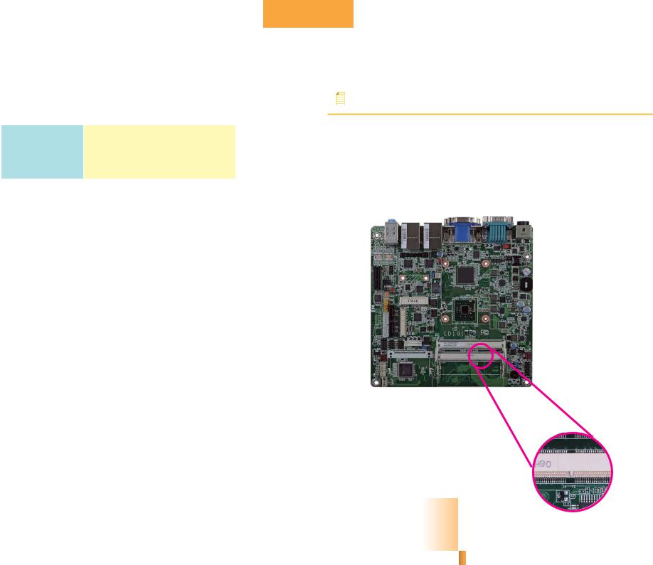
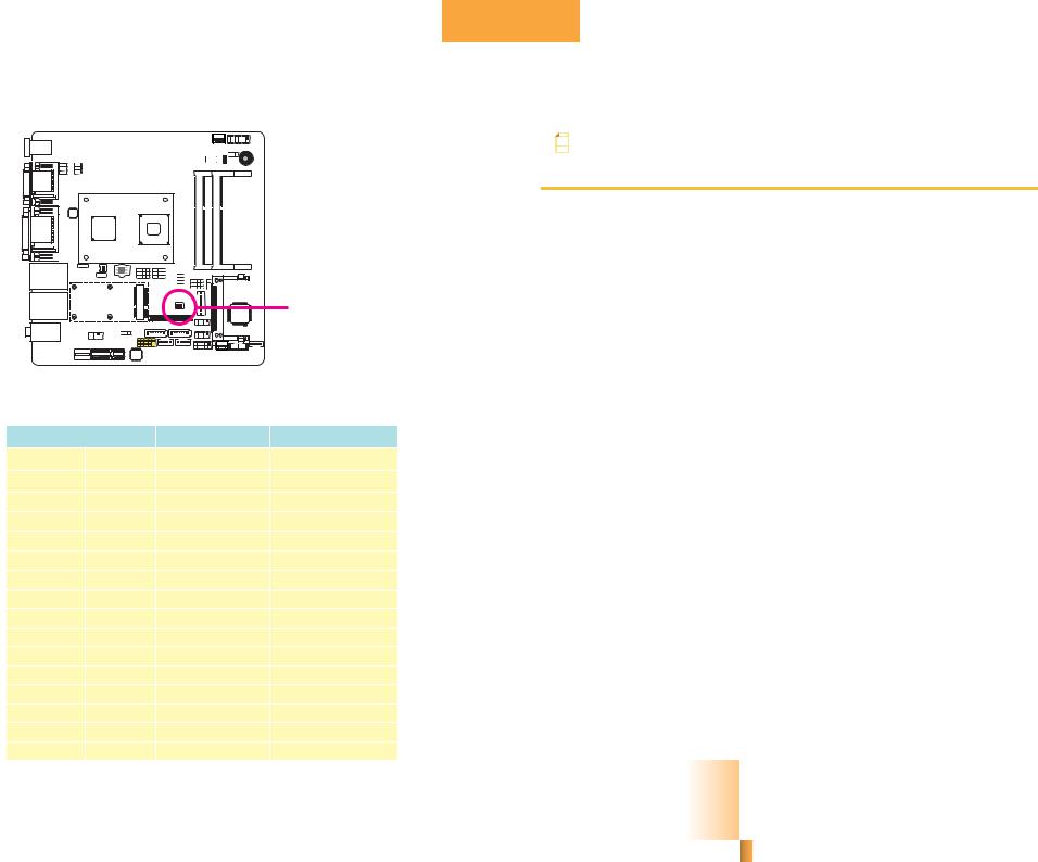
System Memory
Important:
When the Standby Power LED lit red, it indicates that there is power on the system board. Power-off the PC then unplug the power cord prior to installing any devices. Failure to do so will cause severe damage to the motherboard and components.
Standby
Power LED
DDR3-1 |
DDR3-2 |
Features
•Two 204-pin DDR3 SODIMM sockets (-N2550/-N2800)
•One 204-pin DDR3 SODIMM sockets (-N2600)
•Supports 800MHz(-N2600)/1066MHz (-N2550/-N2800) DDR3 SDRAM
•Single channel memory interface
•Supports maximum of 4GB (-N2550, -N2800)/2GB (-N2600) system memory
9
Chapter 2 Hardware Installation |
www.dfi.com |
The system board supports the following memory interface.
Single Channel (SC)
Data will be accessed in chunks of 64 bits (8B) from the memory channels.
DIMMs are on the same channel.
DIMMs in a channel can be identical or Single Channel completely different. However, we highly
recommend using identical DIMMs. Not all slots need to be populated.
Chapter 2
Installing the DIMM Module
Note:
The system board used in the following illustrations may not resemble the actual board. These illustrations are for reference only.
1.Make sure the PC and all other peripheral devices connected to it has been powered down.
2.Disconnect all power cords and cables.
3.Locate the SODIMM socket on the system board.
4.Note the key on the socket. The key ensures the module can be plugged into the socket in only one direction.
10
Chapter 2 Hardware Installation |
www.dfi.com |
Chapter 2
5.Grasping the module by its edges, align the module into the socket at an approximately 30 degrees angle. Apply firm even pressure to each end of the module until it slips down into the socket. The contact fingers on the edge of the module will almost completely disappear inside the socket.
6.Push down the module until the clips at each end of the socket lock into position. You will hear a distinctive “click”, indicating the module is correctly locked into position.
Clip |
Clip |
|
11
Chapter 2 Hardware Installation |
www.dfi.com |
Chapter 2
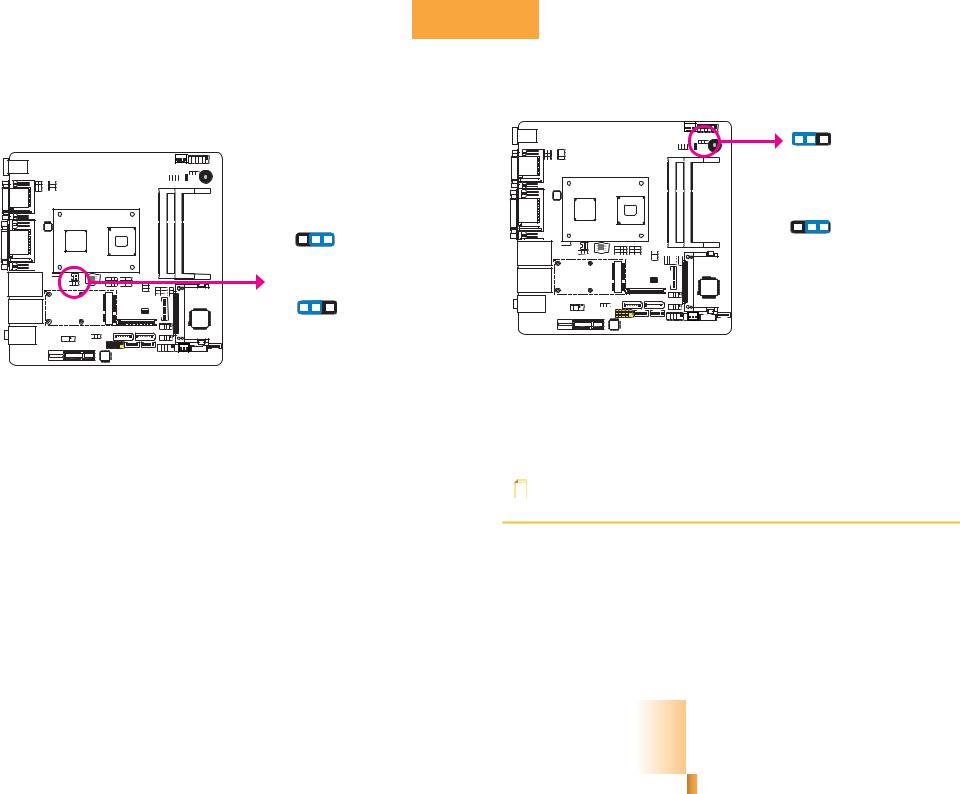
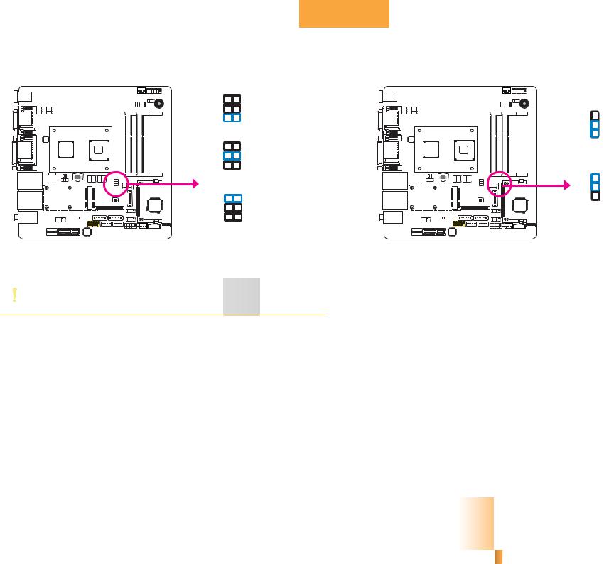
Jumper Settings |
Power-on Select |
|
|
|
Clear CMOS Data |
JP10 |
1 |
2 |
3 |
|
|
|
|
|
|
|
1-2 On: |
||
|
|
|
|
Power-on via power button |
||
|
|
|
|
(default) |
||
|
3 |
2 |
1 |
1 |
2 |
3 |
|
|
|
|
|||
|
1-2 On: Normal |
2-3 On: |
||||
|
Power-on via AC power |
|||||
JP4 |
(default) |
|
|
|
||
|
|
|
|
|
|
|
|
3 |
2 |
1 |
|
|
|
2-3 On: |
Clear CMOS Data |
If you encounter the following,
a)CMOS data becomes corrupted.
b)You forgot the supervisor or user password.
you can reconfigure the system with the default values stored in the ROM BIOS. To load the default values stored in the ROM BIOS, please follow the steps below.
1.Power-off the system and unplug the power cord.
2.Set JP4 pins 2 and 3 to On. Wait for a few seconds and set JP4 back to its default setting, pins 1 and 2 On.
3.Now plug the power cord and power-on the system.
JP10 is used to select the method of powering on the system. If you want the system to power-on whenever AC power comes in, set JP10 pins 2 and 3 to On. If you want to use the power button, set pins 1 and 2 to On.
When using the JP10 “Power On” feature to power the system back on after a power failure occurs, the system may not power on if the power lost is resumed within 5 seconds (power flicker).
Note:
In order to ensure that power is resumed after a power failure that recovers within a 5 second period, JP10 must be set to pins 2-3 and the “AC Power Lose” in CMOS is set to “On”.
12
Chapter 2 Hardware Installation |
www.dfi.com |
Chapter 2
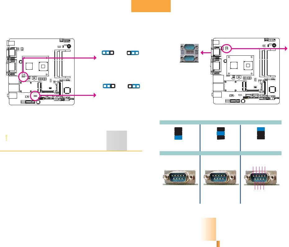
USB Power Select |
COM 1 RS232/RS422/RS485 Select |
||
|
|
|
|
|
|
|
|
USB 0-3 |
1 |
2 |
3 |
1 |
2 |
3 |
JP2 |
|
|
|
|
|
|
|
|
(JP3) |
1-2 On: +5V |
2-3 On: |
|
||||
|
|
||||||
|
(default) |
+5V_standby |
|
||||
|
|
|
|
|
|
|
COM 1 |
1 |
2 |
3 |
1 |
2 |
3 |
USB 4-5 |
1-2 On: +5V |
2-3 On: |
(JP5) |
||
|
(default) |
+5V_standby |
JP3 and JP5 are used to select the power of the USB ports. Selecting +5V_standby will allow you to use a USB device to wake up the system.
Important:
If you are using the Wake-On-USB Keyboard/Mouse function for 2 USB ports, the +5V_standby power source of your power supply must support ≥1.5A. For 3 or more USB ports, the +5V_standby power source of your power supply must support ≥2A.
JP2 (for COM1) is used to configure the COM port to RS232, RS422 (Full Duplex) or RS485. The pin function of the COM 1 port will vary according to the jumper’s setting.
|
|
|
|
|
|
|
|
|
|
|
|
|
|
|
|
|
|
|
|
|
|
JP2 |
||||||||||||
6 |
|
|
|
|
|
|
|
|
5 |
6 |
|
|
|
|
|
|
|
|
|
|
|
|
|
|
5 |
|||||||||
|
|
|
|
|
|
|
|
|
|
|
|
|
|
|
||||||||||||||||||||
|
|
|
|
|
|
|
|
|
|
|
|
|
|
|
||||||||||||||||||||
|
|
|
|
|
|
|
|
|||||||||||||||||||||||||||
4 |
|
|
|
|
|
|
|
|
3 |
4 |
|
|
|
|
|
|
|
|
|
|
|
3 |
||||||||||||
|
|
|
|
|
|
|
|
|
|
|
|
|
|
|||||||||||||||||||||
|
|
|
|
|
|
|
|
|
|
|
|
|
|
|||||||||||||||||||||
|
|
|
|
|
|
|
|
|||||||||||||||||||||||||||
2 |
|
|
|
|
|
|
|
|
1 |
2 |
|
|
|
|
|
|
|
|
|
|
|
|
1 |
|||||||||||
|
|
|
|
|
|
|
|
|
|
|
|
|
|
|
||||||||||||||||||||
|
|
|
|
|
|
|
|
|
|
|
|
|
|
|
||||||||||||||||||||
|
|
|
|
|
|
|
|
|||||||||||||||||||||||||||
1-2 On: RS232 |
3-4 On: RS422 |
|||||||||||||||||||||||||||||||||
|
(default) |
|||||||||||||||||||||||||||||||||
|
|
Full Duplex |
||||||||||||||||||||||||||||||||
|
|
|
|
|
|
|
|
|
|
|
|
|
|
|
||||||||||||||||||||
|
|
|
|
|
|
|
|
|
|
|
|
|
|
|
|
|
|
COM 1 |
||||||||||||||||
DCDRD TD DTRGND |
RXD+ RXDTXD+ TXD- N.C. |
|||||||||||||||||||||||||||||||||
1 |
2 |
3 |
4 |
5 |
|
1 |
2 |
3 |
4 |
5 |
|
|||||||||||||||||||||||
|
|
|
|
|
|
|
|
|
|
|
|
|
|
|
|
|
|
|
|
|
|
|
|
|
|
|
|
|
|
|
|
|
|
|
6 |
|
7 |
|
8 |
|
9 |
|
|
6 |
|
7 |
|
8 |
|
9 |
|
|
|
|
|||||||||||||||
|
|
|
|
|
|
|
|
|
|
|
|
|||||||||||||||||||||||
- |
|
|
|
|
|
|
|
N.C. |
||||||||||||||||||||||||||
|
|
|
|
|
|
|
|
|
RI- |
N.C. |
||||||||||||||||||||||||
DSRRTS- CTS |
|
|
|
|
|
|
|
N.C. N.C. |
||||||||||||||||||||||||||
|
RS232 |
|
|
|
|
|
RS422 |
|||||||||||||||||||||||||||
|
|
|
|
|
|
|
|
|
|
|
|
|
|
Full Duplex |
||||||||||||||||||||
6 
 5
5
4 
 3
3
2 
 1
1
5-6 On: RS485
DATA+-
DATAN.C.N.C.N.C.
1 2 3 4 5
6 7 8 9 N.C.N.C.N.C.N.C. RS485
13
Chapter 2 Hardware Installation |
www.dfi.com |
Chapter 2
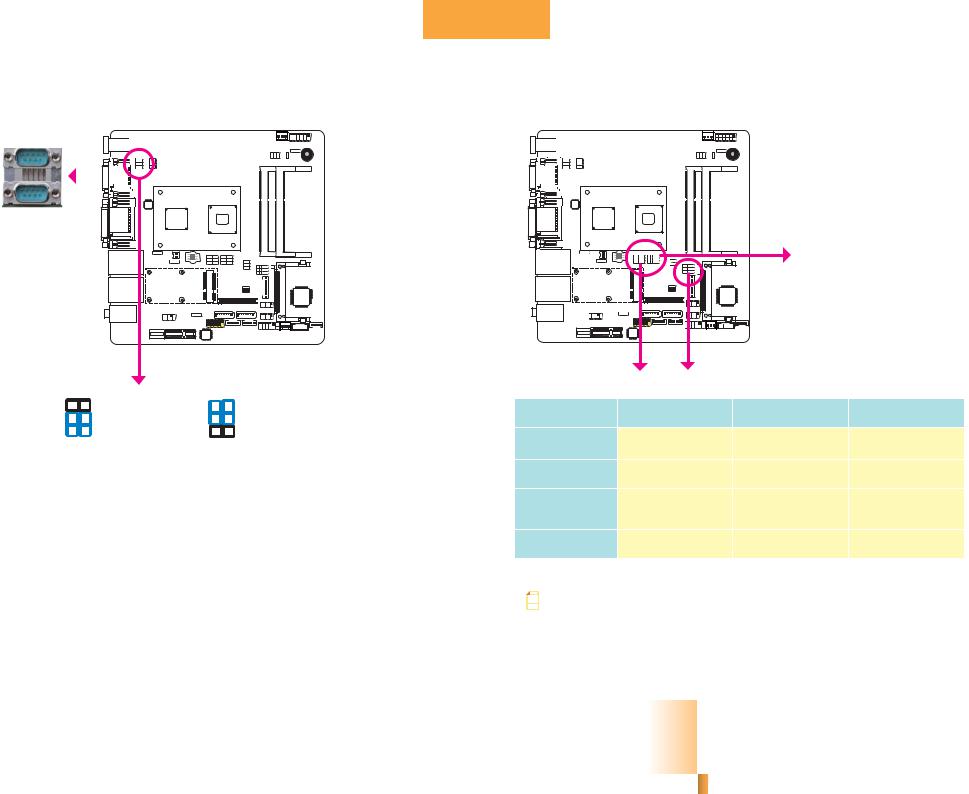
COM 1 RS232/Power Select |
Mini PCIe/mSATA Select |
|||||||||||||||||
|
|
|
|
|
|
|
|
|
|
|
|
|
|
|
|
|
|
|
|
|
|
|
|
|
|
|
|
|
|
|
|
|
|
|
|
|
|
|
|
|
|
|
|
|
|
|
|
|
|
|
|
|
|
|
|
|
|
|
|
|
|
|
|
|
|
|
|
|
|
|
|
|
|
|
|
|
|
|
|
|
|
|
|
|
|
|
|
|
|
|
|
|
|
|
|
|
|
|
|
|
|
|
|
|
|
|
|
|
|
|
|
|
|
|
|
|
|
|
|
|
|
|
|
|
|
|
|
|
|
|
|
|
|
|
|
|
|
|
|
|
|
|
|
|
|
|
|
|
|
|
|
COM 1
JP1
6 |
5 |
6 |
5 |
4 |
3 |
4 |
3 |
2 |
1 |
2 |
1 |
1-3, 2-4 On: RS232 |
3-5 (+5V), 4-6 (+12V) On: |
(default) |
RS232 with power |
JP1 is used to configure the Serial COM 1 port to pure RS232 or RS232 with power.
|
JP7 |
JP6 |
JP11 |
mSATA/ Mini |
JP6 |
JP7 |
JP11 |
|
PICe Select |
||||
|
|
|
||
Mini PCIe |
N/A |
1-2,4-5,7-8,10-11 On |
2-3,5-6,8-9,11-12 On |
|
(PCIe x1 & USB) |
(default) |
|||
|
|
|
||
mSATA |
2-3,5-6,8-9,11-12 On |
2-3,5-6,8-9,11-12 On |
N/A |
|
|
||||
SATA 1 |
1-2,4-5,7-8,10-11 On |
N/A |
N/A |
|
|
||||
|
(default) |
|||
|
|
|
||
PCIe x1 Slot |
N/A |
N/A |
1-2,4-5,7-8,10-11 On |
|
|
(default) |
|||
|
|
|
||
Note: |
|
|
|
|
The mSATA and Mini PCIe cannot be used at the same time. |
|
|||
|
|
|
|
|
14
Chapter 2 Hardware Installation |
www.dfi.com |
Chapter 2
LVDS Panel Select
Note:
The default setting is eDP.
1. 1366x768: N2000 series processor supports eDP only.
2. 1600x1200: N2000 series processor supports DP only.
3. 1920x1080: D2000 series processor supports eDP only.
4. 1920x1200: D2000 series processor supports DP only.
 SW1
SW1
SW1 is used to select the resolution of the LVDS panel on the system board.
LVDS Panel Select |
Channel |
|
SW2 |
|
|
800x600 |
6/18 bit |
Single |
|
1-4 On |
|
1024x768 |
6/18 bit |
Single |
2-4 On, 1 Off |
|
|
1024x768 |
8/24 bit |
Single |
1,3,4 On, 2 Off |
|
|
1280x768 |
6/18 bit |
Single |
3-4 |
On, 1-2 Off |
|
1280x800 |
6/18 bit |
Single |
1,2,4 On, 3 Off |
|
|
1280x960 |
6/18 bit |
Single |
2,4 |
On, 1,3 Off |
|
1280x1024 |
8/24 bit |
Dual |
1,4 |
On, 2,3 Off |
|
1366x768 |
6/18 bit |
Single |
4 On, 1-3 Off |
|
|
1366x768 |
8/24 bit |
Single |
1-3 On, 4 Off |
*1 |
|
1440x900 |
8/24 bit |
Dual |
2-3 On, 1,4 Off |
|
|
1400x1050 |
8/24 bit |
Dual |
1,3 |
On, 2,4 Off |
|
1600x900 |
8/24 bit |
Dual |
3 On, 1,2,4 Off |
|
|
1680x1050 |
8/24 bit |
Dual |
1-2 |
On, 3-4 Off |
|
1600x1200 |
8/24 bit |
Dual |
2 On, 1,3,4 Off |
*2 |
|
1920x1080 |
8/24 bit |
Dual |
1 On, 2-4 Off |
*3 |
|
1920x1200 |
8/24 bit |
Dual |
|
1-4 Off |
*4 |
|
|
||||
|
|
|
|
|
15 |
Chapter 2 Hardware Installation |
|
|
|
www.dfi.com |
|
Chapter 2
LVDS Panel Power Select |
LVDS Brightness Control Select |
|
6 |
5 |
|
|
|
4 |
3 |
|
3 |
|
2 |
1 |
|
|
|
|
2 |
||
|
1-2 On: +12V |
|
||
|
|
1 |
||
|
|
|
|
|
|
6 |
5 |
|
1-2 On: |
|
4 |
3 |
|
LED Backlight Panel (default) |
|
2 |
1 |
|
|
JP9 |
3-4 On:+5V |
JP12 |
3 |
|
|
|
|
|
2 |
|
6 |
5 |
|
1 |
|
4 |
3 |
|
2-3 On: CCFL Backlight Panel |
|
2 |
1 |
|
|
|
|
|
||
5-6 On: +3.3V |
(default) |
JP9 is used to select the power supplied to the LCD LVDS panel connector. |
JP12 is used to select the brightness to the LCD panel. |
Important:
Before powering-on the system, make sure JP9’s setting matches the LCD panel’s specification. Selecting the incorrect voltage will seriously damage the LCD panel.
16
Chapter 2 Hardware Installation |
www.dfi.com |
Chapter 2
Rear Panel I/O Ports
COM 2 |
VGA |
LAN 1 |
LAN 2 |
Line-in |
|
||||
|
|
|
||
DC-in |
|
|
|
Line-out |
|
|
|
|
Mic-in |
COM 1 |
DVI-I |
USB 0-1 |
USB 2-3 |
|
|
(DVI-D signal) |
|
|
|
The rear panel I/O ports consist of the following:
•1 4-pin 9-24V DC-in jack or 4-pin power connector (optional)
•2 Serial COM ports
•1 VGA port
•1 DVI-I port (DVI-D signal)
•4 USB 2.0/1.1 ports
•2 LAN ports
•Mic-in jack
•Line-in jack
•Line-out jack
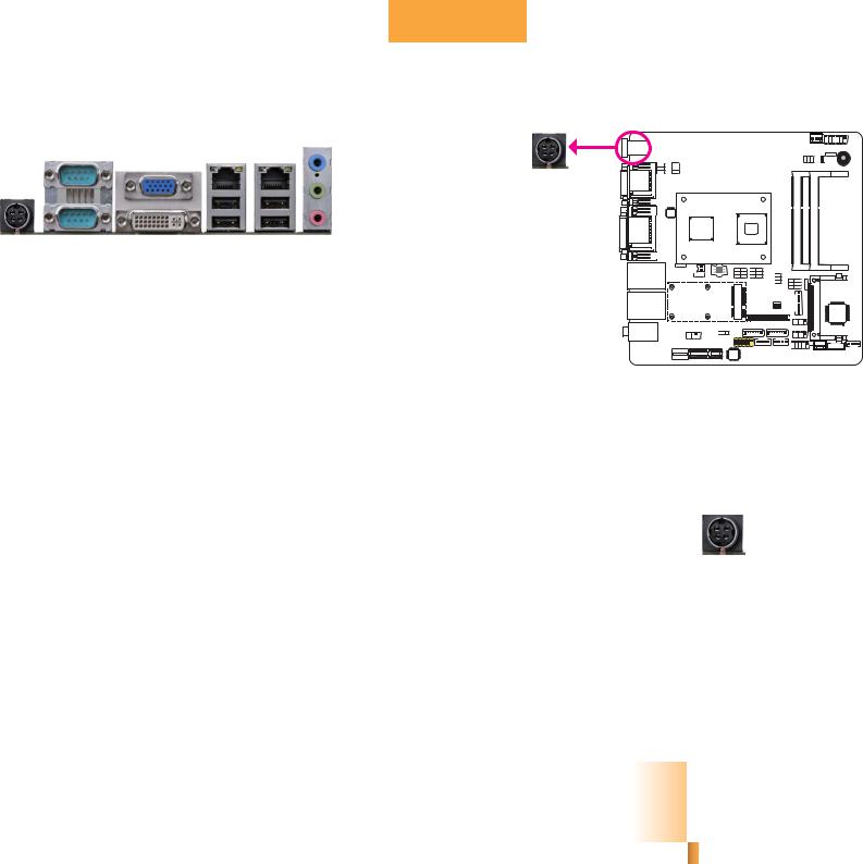
DC-in 9~24V
Connect a DC power cord to this jack. Use a power adapter with 9~24V DC output voltage. Using a voltage higher than the recommended one may fail to boot the system or cause damage to the system board.
1: DC-IN |
|
|
|
2: DC-IN |
|
|
|
|
|
3: GND |
|
|
|
4: GND |
|
|
17
Chapter 2 Hardware Installation |
www.dfi.com |
Chapter 2
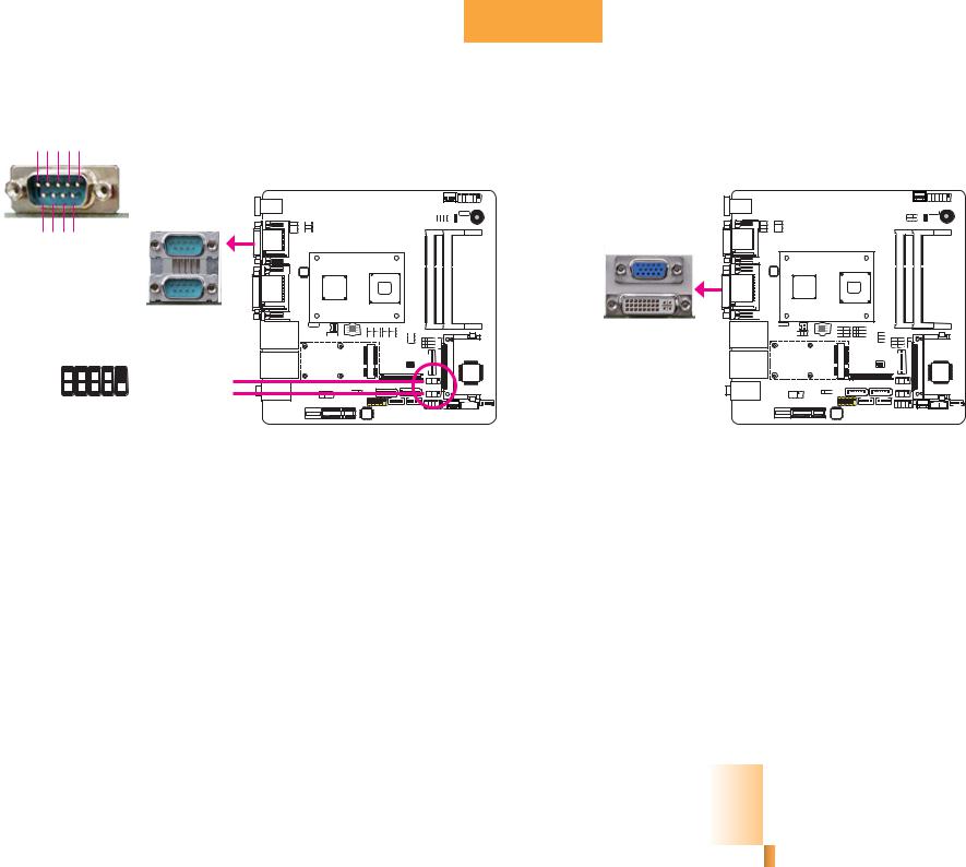
COM (Serial) Ports |
Graphics Interfaces |
-DCDRDTD-DTRGND 1 2 3 4 5
The display ports consist of the following:
•VGA port
•DVI-I port (DVI-D signal)
6 7 8 9
DSRRTS- CTSRI-
|
COM2: RS232 |
COM 2 |
VGA |
RS232 |
|
|
|
|
COM 1 |
|
|
|
|
COM 1: |
|
|
|
RS232/422/485 |
DVI-I |
-DSR -DTR RD |
-CTS |
|
(VI-D signal) |
|
|
||
2 |
9 |
COM 3: RS232 |
|
1 |
|
||
GND TD -DCD |
-RI -RTS |
COM 4: RS232 |
|
|
|
COM 2 to COM 4 are fixed at RS232.
The pin function of COM 1 port will vary according to JP2’s setting. Refer to “COM1/COM2 RS232/RS422/RS485 Select” in this chapter for more information.
The serial ports are asynchronous communication ports with 16C550A-compatible UARTs that can be used with modems, serial printers, remote display terminals, and other serial devices.
Connecting External Serial Ports
Your COM port may come mounted on a card-edge bracket. Install the card-edge bracket to an available slot at the rear of the system chassis then insert the serial port cable to the COM connector. Make sure the colored stripe on the ribbon cable is aligned with pin 1 of the COM connector.
BIOS Setting
Configure the serial ports in the Advanced menu (“Super IO Configuration” submenu) of the BIOS. Refer to chapter 3 for more information.
VGA Port
The VGA port is used for connecting a VGA monitor. Connect the monitor’s 15-pin D-shell cable connector to the VGA port. After you plug the monitor’s cable connector into the VGA port, gently tighten the cable screws to hold the connector in place.
DVI-I Port
The DVI-I port is used to connect an LCD monitor.
Connect the display device’s cable connector to the DVI-I port. After you plug the cable connector into the port, gently tighten the cable screws to hold the connector in place.
BIOS Setting
Configure the display device in the Chipset menu (“North Bridge Configuration” submenu) of the BIOS. Refer to chapter 3 for more information.
Driver Installation
Install the graphics driver. Refer to chapter 4 for more information.
18
Chapter 2 Hardware Installation |
www.dfi.com |
Chapter 2
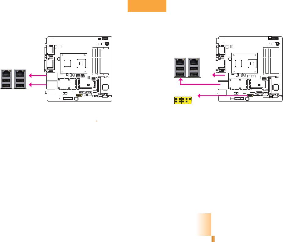
RJ45 LAN Ports |
|
|
|
|
|
USB Ports |
|
|
|
|
|
||
|
|
|
|
|
|
|
|
|
|
|
|
|
|
|
|
|
|
|
|
|
|
|
|
|
|
|
|
|
|
|
|
|
|
|
|
|
|
|
|
|
|
|
|
|
|
|
|
|
|
|
|
|
|
|
|
USB 2.0 |
LAN 1 |
LAN 2 |
USB 1 |
USB 3 |
|
|
LAN 1 |
USB 0 |
USB 2 |
|
LAN 2
USB 4-5 |
N.C. GND +Data DataVCC |
2 |
10 |
1 |
9 |
Features
•2 Intel 82574L Gigabit Ethernet controllers; or 2 Intel® I210 PCI Express Gigabit Ethernet controllers (optional)
The LAN ports allow the system board to connect to a local area network by means of a network hub.
BIOS Setting
Configure the onboard LAN in the Chipset menu (“South Bridge Configuration” submenu) of the BIOS. Refer to chapter 3 for more information.
Driver Installation
Install the LAN drivers. Refer to chapter 4 for more information.
+Data DataVCC |
Key |
GND |
|
USB 2.0
The USB device allows data exchange between your computer and a wide range of simultaneously accessible external Plug and Play peripherals.
The system board is equipped with four onboard USB 2.0/1.1 ports (USB 0-1/2-3). The one 10-pin connector allow you to connect 2 additional USB 2.0/1.1 ports (USB 4-5). The additional USB port may be mounted on a card-edge bracket. Install the card-edge bracket to an available slot at the rear of the system chassis and then insert the USB port cables to a connector.
BIOS Setting
Configure the onboard USB in the Advanced menu (“USB Configuration” submenu) of the BIOS. Refer to chapter 3 for more information.
Driver Installation
You may need to install the proper drivers in your operating system to use the USB device. Refer to your operating system’s manual or documentation for more information.
19
Chapter 2 Hardware Installation |
www.dfi.com |
Chapter 2
Wake-On-USB Keyboard/Mouse
The Wake-On-USB Keyboard/Mouse function allows you to use a USB keyboard or USB mouse to wake up a system from the S3 (STR - Suspend To RAM) state. To use this function:
•Jumper Setting
JP3 and JP5 must be set to “2-3 On: +5V_standby”. Refer to “USB Power Select” in this chapter for more information.
Important:
If you are using the Wake-On-USB Keyboard/Mouse function for 2 USB ports, the +5V_standby power source of your power supply must support ≥1.5A. For 3 or more USB ports, the +5V_standby power source of your power supply must support ≥2A.
Audio
Rear audio
Line-in
Line-out
Mic-in
JD-Line2 Key JD-Mic2 Signal Presence GND |
|
||
2 |
10 |
|
|
1 |
9 |
Front audio |
|
Sense IO Front R-Line2 R-Mic2 L-Mic2 |
L-Line2 |
||
|
|||
Rear Audio
The system board is equipped with 3 audio jacks. A jack is a one-hole connecting interface for inserting a plug.
•Mic-in Jack (Pink)
This jack is used to connect an external microphone.
•Line-in Jack (Light Blue)
This jack is used to connect any audio devices such as Hi-fi set, CD player, tape player, AM/FM radio tuner, synthesizer, etc.
•Line-out Jack (Lime)
This jack is used to connect a headphone or external speakers.
Front Audio
The front audio connector allows you to connect to the second line-out and mic-in jacks that are at the front panel of your system.
20
Chapter 2 Hardware Installation |
www.dfi.com |
Chapter 2
BIOS Setting
Configure the onboard audio in the Chipset menu (“South Bridge” submenu) of the BIOS. Refer to chapter 3 for more information.
Driver Installation
Install the audio driver. Refer to chapter 4 for more information.
I/O Connectors
Digital I/O Connector
Digital I/O Power Connector
|
|
|
|
|
|
|
|
|
|
|
|
|
|
|
|
|
|
|
|
|
|
|
|
|
|
|
|
|
|
|
|
|
|
Ground 5VSB |
||||||||||
|
|
|
|
|
|
|
|
|
|
|
|
|
|
|
|
|
|
|
|
|
|
|
|
|
|
|
|
|
|
|
|
|
|
|||||||||||
|
|
|
|
|
|
|
|
|
|
|
|
|
|
|
|
|
|
|
|
|
|
|
|
|
|
|
|
|
|
|
|
|
|
|||||||||||
|
|
|
|
|
|
|
|
|
|
|
|
|
|
|
|
|
|
|
|
|
|
|
|
|
|
|
|
|
|
|
||||||||||||||
|
|
|
|
|
|
|
|
|
|
|
|
|
|
|
|
|
|
|
|
|
|
|
|
|
|
|
|
|
|
|
||||||||||||||
|
|
|
|
|
|
|
|
|
|
|
|
|
|
|
|
|
|
|
|
|
|
|
|
|
|
|
|
|
|
Digital I/O power |
+12V |
|
|
|
|
|
+5V |
|||||||
|
|
|
|
|
|
|
|
|
|
|
|
|
|
|
|
|
|
|
|
|
|
|
|
|
|
|
|
|
|
|
|
|
|
|
|
|
|
|
|
|
|
|
|
|
|
|
|
|
|
|
|
|
|
|
|
|
|
|
|
|
|
|
|
|
|
|
|
|
|
|
|
|
|
|
|
|
|
|
|
|
|
|
|
|
|
|
|
|
|
|
|
|
|
|
|
|
|
|
|
|
|
|
|
|
|
|
|
|
|
|
|
|
|
|
|
|
|
|
|
|
|
|
|
|
|
|
|
|
|
|
|
|
|
|
|
|
|
|
|
|
|
|
|
|
|
|
|
|
|
|
|
|
|
|
|
|
|
|
|
|
|
|
|
|
|
|
1 |
|
|
|
|
|
|
4 |
|
||||
|
|
|
|
|
|
|
|
|
|
|
|
|
|
|
|
|
|
|
|
|
|
|
|
|
|
|
|
|
|
|
|
|
|
|
|
|
|
|
|
|
|
|
|
|
|
|
|
|
|
|
|
|
|
|
|
|
|
|
|
|
|
|
|
|
|
|
|
|
|
|
|
|
|
|
|
|
|
|
|
|
|
|
|
|
|
|
|
|
|
|
|
|
|
|
|
|
|
|
|
|
|
|
|
|
|
|
|
|
|
|
|
|
|
|
|
|
|
|
|
|
|
|
|
|
|
|
|
|
|
|
|
|
|
|
|
|
|
|
|
|
|
|
|
|
|
|
|
|
|
|
|
|
|
|
|
|
|
|
|
|
|
|
|
|
|
|
|
|
|
|
|
|
|
|
|
|
|
|
|
|
|
|
|
|
|
|
|
|
|
|
|
|
|
|
|
|
|
|
|
|
|
|
|
|
|
|
|
|
|
|
|
|
|
|
|
|
|
|
|
|
|
|
|
|
1 11
Digital I/O |
2 |
12 |
|
The 12-bit Digital I/O connector provides powering-on function to external devices that are connected to these connectors.
Digital I/O Connector
Pins |
Function |
Pins |
Function |
1 |
|
7 |
|
DIO0 |
DIO6 |
||
2 |
DIO1 |
8 |
DIO7 |
3 |
DIO2 |
9 |
DIO8 |
|
|
||
4 |
DIO3 |
10 |
DIO9 |
|
|
||
5 |
DIO4 |
11 |
DIO10 |
|
|
||
6 |
DIO5 |
12 |
DIO11 |
|
|
21
Chapter 2 Hardware Installation |
www.dfi.com |
Loading...