

DFI CA64-EC User Manual

CA64-EC
Rev. A+
System Board Users Manual
Carte Mère Manuel Pour Utilisateur
System-Platine Benutzerhandbuch
Tablero Electrónico del Sistema Manual del Usuario
45100039

Copyright
This publication contains information that is protected by copyright.
No part of it may be reproduced in any form or by any means or
used to make any transformation/adaptation without the prior
written permission from the copyright holders.
This publication is provided for informational purposes only. The
manufacturer makes no representations or warranties with respect to
the contents or use of this manual and specifically disclaims any
express or implied warranties of merchantability or fitness for any
particular purpose. The user will assume the entire risk of the use or
the results of the use of this document. Further, the manufacturer
reserves the right to revise this publication and make changes to its
contents at any time, without obligation to notify any person or
entity of such revisions or changes.
© 2000. All Rights Reserved.
Trademarks
Microsoft® MS-DOS®, WindowsTM, Windows® 95, Windows® 98,
Windows® 98 SE, Windows® 2000 and Windows NT® 4.0 are
registered trademarks of Microsoft Corporation. Intel®, Pentium® III
and Celeron
TM
are registered trademarks of Intel Corporation. VIA
CyrixIII is a registered trademark of VIA Technologies, Inc. Award is a
registered trademark of Award Software, Inc. Other trademarks and
registered trademarks of products appearing in this manual are the
properties of their respective holders.
Caution:
Danger of explosion if battery incorrectly replaced.
Replace only with the same or equivalent type recommended by the
manufacturer.
Dispose of used batteries according to the battery manufacturers
instructions.

FCC and DOC Statement on Class B
This equipment has been tested and found to comply with the limits
for a Class B digital device, pursuant to Part 15 of the FCC rules.
These limits are designed to provide reasonable protection against
harmful interference when the equipment is operated in a residential
installation. This equipment generates, uses and can radiate radio
frequency energy and, if not installed and used in accordance with
the instruction manual, may cause harmful interference to radio
communications. However, there is no guarantee that interference
will not occur in a particular installation. If this equipment does cause
harmful interference to radio or television reception, which can be
determined by turning the equipment off and on, the user is
encouraged to try to correct the interference by one or more of the
following measures:
Reorient or relocate the receiving antenna.
Increase the separation between the equipment and the receiver.
Connect the equipment into an outlet on a circuit different from
that to which the receiver is connected.
Consult the dealer or an experienced radio TV technician for
help.
Notice:
1. The changes or modifications not expressly approved by the
party responsible for compliance could void the user's authority
to operate the equipment.
2. Shielded interface cables must be used in order to comply with
the emission limits.

4
Quick Setup Guide
1
Quick Setup
Guide
Table of Contents
Chapter 1
Quick Setup Guide.............................................
Chapter 2
English......................................................................
Chapter 3
Français (French).................................................
Chapter 4
Deutsch (German)................................................
Chapter 5
Español (Spanish)..................................................
5
23
39
57
75

5
1
Quick Setup Guide
Quick Setup
Guide
Chapter 1 - Quick Setup Guide
Table of Contents
1.1 System Board Layout..................................................................................................
1.2 Jumpers.....................................................................................................................................
1.3 Ports and Connectors................................................................................................
1.4 Award BIOS Setup Utility.......................................................................................
6
7
10
18
6
Quick Setup Guide
1
Quick Setup
Guide
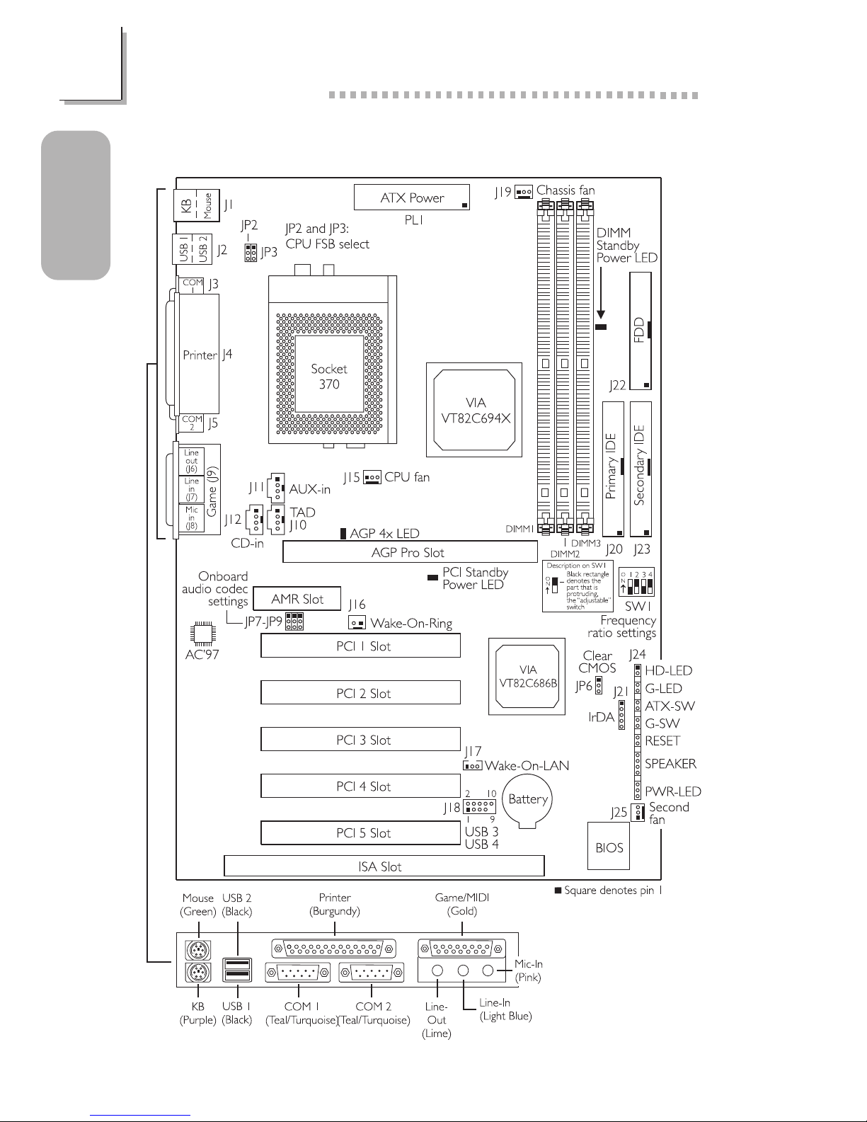
1.1 System Board Layout

7
1
Quick Setup Guide
Quick Setup
Guide
1.2 Jumpers
1.2.1 Frequency Ratio Settings - SW1
Black rectangle
denotes the part
that is protruding,
the adjustable
switch.
Important:
The frequency ratio of some processors shown in the table may
have been locked by the manufacturer. If you are using this kind
of processor, setting an extended ratio for the processor will have
no effect. The system will instead use its factory default ratio.
The frequency ratio of processors greater than 8x has been
locked by the manufacturer and will no longer have the flexibility
of using extended ratios. Therefore, the system will use the
processors factory default ratio.
--- --- 4x
--- 4.5x
333MHz 5x
Processor
SW1
66MHz
100MHz
Freq.
Ratio
5.5x
Processor
SW1
66MHz 100MHz
Freq.
Ratio
400MHz
433MHz
466MHz
500MHz
6x
6.5x
7x
7.5x
8x533MHz
500MHz
366MHz
133MHz
533MHz
133MHz
650MHz
700MHz
933MHz
866MHz
800MHz
750MHz 1GHz
800MHz 1.067GHz*
667MHz
733MHz
300MHz
300AMHz
550MHz
600MHz
600MHz
8
Quick Setup Guide
1
Quick Setup
Guide
At the time this document was printed, the CPU marked with
asterisk (*) is not yet available. It is included in the table for
reference only.
The processors supported by the system board support VID
(Voltage Identification). The switching voltage regulator on the
system board will automatically set the voltage regulator
according to the voltage of the processor.
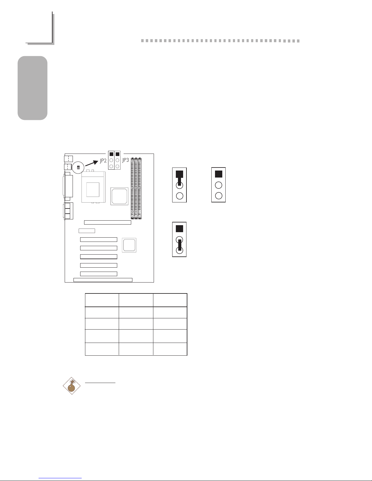
1.2.2 CPUs Front Side Bus - JP2 and JP3
2-3 On
1-2 On All Off
1
2
3
1
2
3
1
2
3
Warning:
Some processors, when overclocked, may result to the processors or
systems instability and are not guaranteed to provide better system
performance. If you are unable to boot your system due to
overclocking, make sure to set these jumpers back to their default
settings.
JP2
1-2 On
2-3 On
All Off
All Off
JP3
1-2 On
2-3 On
2-3 On
All Off
Auto*
66MHz
100MHz
133MHz
* denotes default setting
9
1
Quick Setup Guide
Quick Setup
Guide
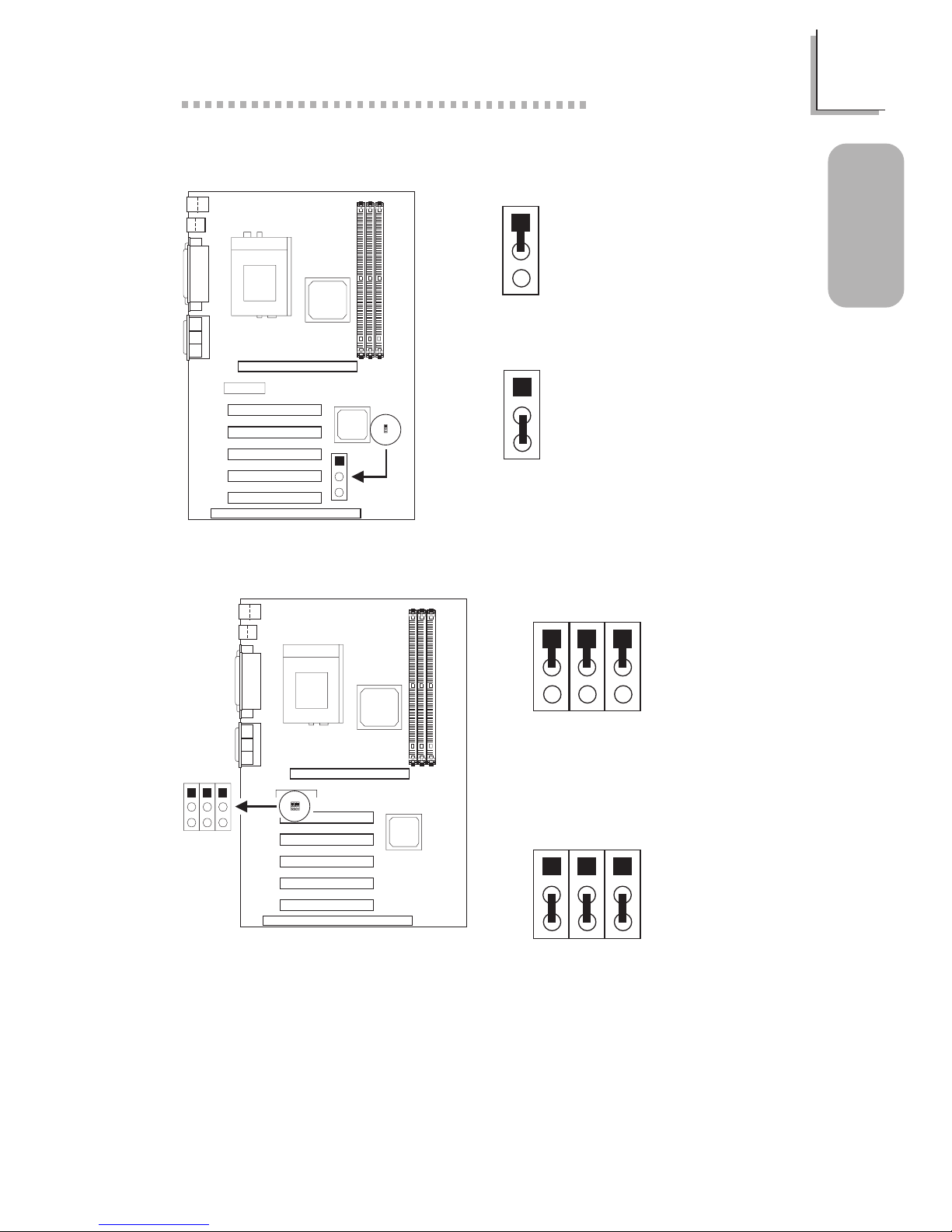
1.2.4 Onboard Audio Codec - JP7, JP8 and JP9
1.2.3 Clear CMOS Data - JP6
2-3 On:
Clear CMOS Data
1-2 On: Normal
(default)
1
2
3
1
2
3
2-3 On:
Disable the Onboard
Audio Codec
1-2 On:
Enable the Onboard
Audio Codec
(default)
1
2
3
JP7 JP9JP8
1
2
3
JP7 JP9JP8

10
Quick Setup Guide
1
Quick Setup
Guide
1.3 Ports and Connectors
1.3.1 PS/2 Mouse and PS/2 Keyboard Ports
Make sure to turn off your
computer prior to
connecting or disconnecting
a mouse or keyboard.
Failure to do so may
damage the system board.
PS/2 Mouse
PS/2 Keyboard
1.3.2 Parallel Port
Parallel Port
11
1
Quick Setup Guide
Quick Setup
Guide
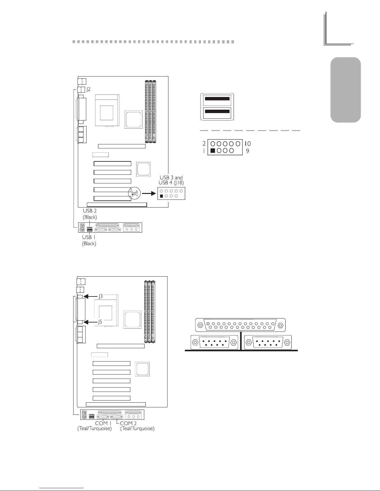
1.3.3 Universal Serial Bus Ports
USB 2
USB 1
USB 3 and
USB 4
1 VCC
2 VCC
3 -Data
4 -Data
5 +Data
6 +Data
7 Ground
8 Ground
9 Key
10 Ground
1.3.4 Serial Ports
COM 1
Serial Port
COM 2
Serial Port
12
Quick Setup Guide
1
Quick Setup
Guide
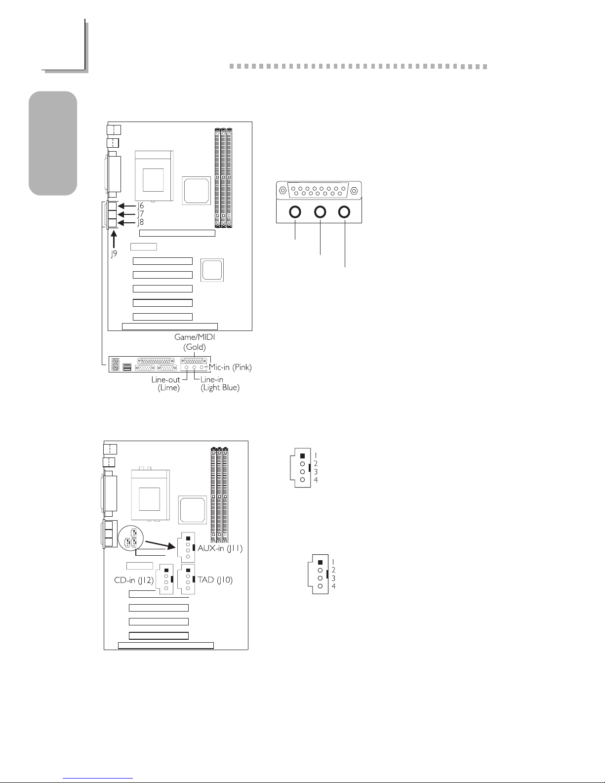
1.3.5 Game/MIDI Port and Audio Jacks
Game/MIDI Por t
Audio Jacks
1.3.6 Internal Audio Connectors
1 Left audio channel
2 Ground
3 Ground
4 Right audio channel
1 Modem-out (from modem)
2 Ground
3 Ground
4 Modem-in (to modem)
TAD
CD-in
AUX-in
Line-out
Line-in
Mic-in
13
1
Quick Setup Guide
Quick Setup
Guide
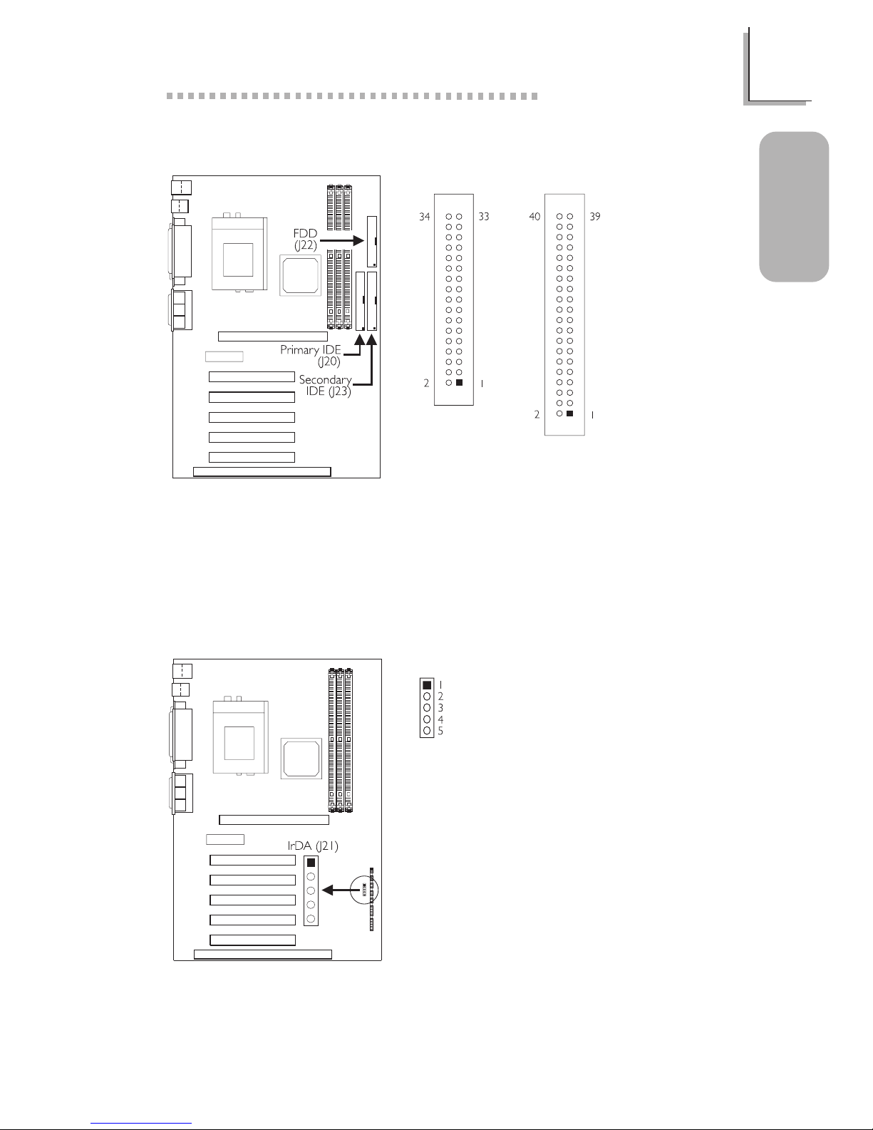
1.3.7 Floppy and IDE Disk Drive Connectors
If you encountered problems while using an ATAPI CD-ROM drive that is
set in Master mode, please set the CD-ROM drive to Slave mode. Some
ATAPI CD-ROMs may not be recognized and cannot be used if
incorrectly set in Master mode.
FDD
IDE
1.3.8 IrDA Connector
1 VCC
2N. C.
3 IRRX
4 Ground
5 IRTX
The sequence of the pin
functions on some IrDA
cable may be reversed from
the pin function defined on
the system board. Make sure
to connect the cable to the
IrDA connector according to
their pin functions.
14
Quick Setup Guide
1
Quick Setup
Guide
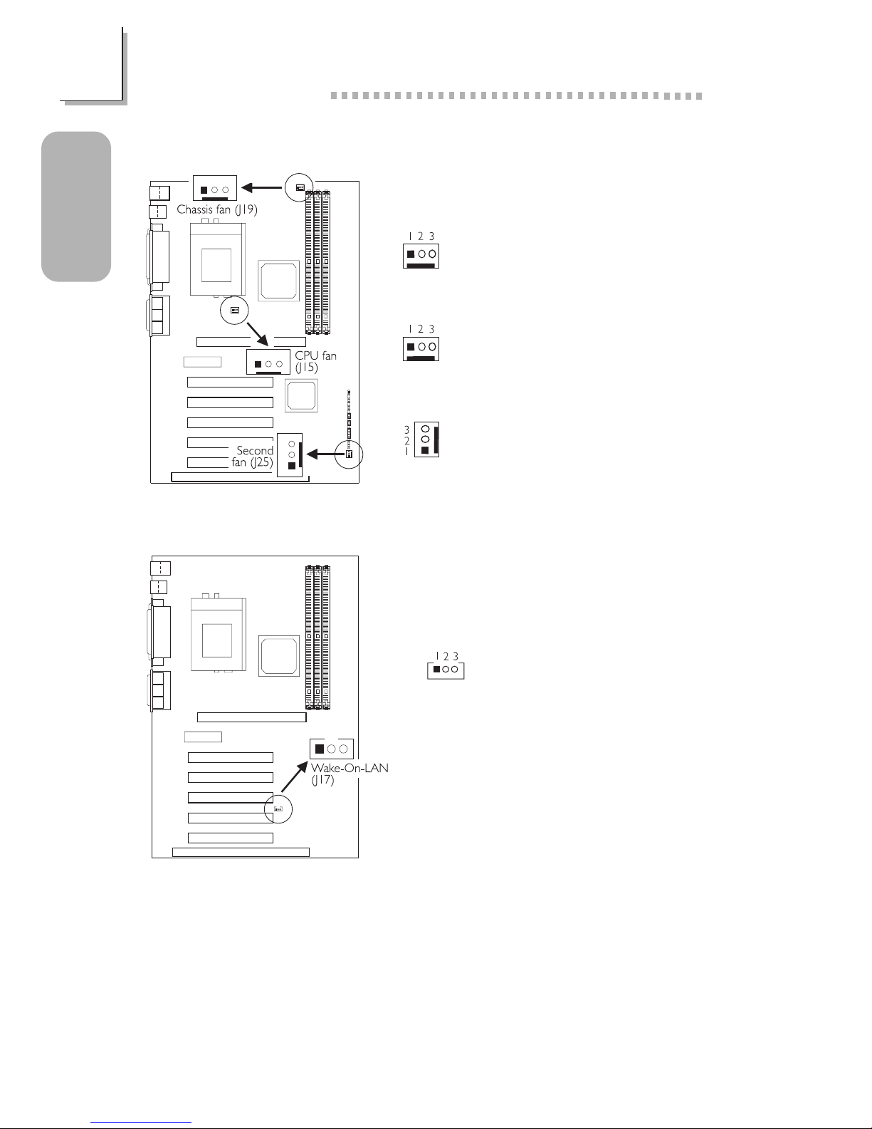
1.3.10 Wake-On-LAN Connector
The 5VSB power source of
your power supply must
support ≥720mA.
1 +5VSB
2 Ground
3 WOL
1.3.9 Fan Connectors
1 On/Off
2 +12V
3 Sense
1 On/Off
2 +12V
3 Sense
1 Ground
2 +12V
3N. C.
CPU Fan
Chassis Fan
Second Fan
15
1
Quick Setup Guide
Quick Setup
Guide
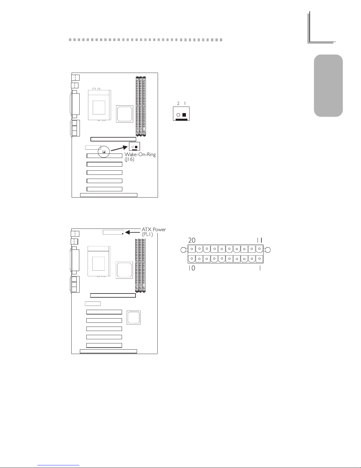
1.3.11 Wake-On-Ring Connector
1 Ground
2 RI#
If you are using a modem
add-in card, the 5VSB power
source of your power supply
must support ≥720mA.
1.3.12 Power Connector
1 3.3V
2 3.3V
3 Ground
4 +5V
5 Ground
6 +5V
7 Ground
8 PW-OK
9 5VSB
10 +12V
11 3.3V
12 -12V
13 Ground
14 PS-ON
15 Ground
16 Ground
17 Ground
18 -5V
19 +5V
20 +5V
The system board requires a minimum of 3.3V/6A electric current.
16
Quick Setup Guide
1
Quick Setup
Guide
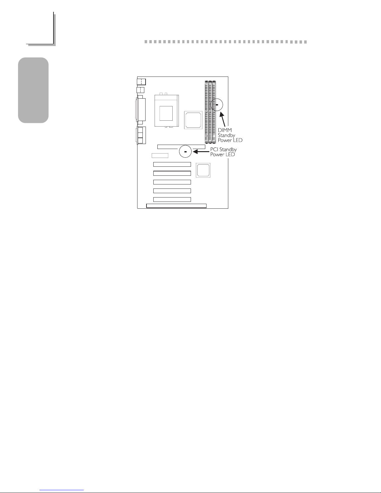
1.3.13 DIMM and PCI Standby Power LEDs
The DIMM Standby Power LED will turn red when the systems power is
on or when it is in the Suspend state (Power On Suspend or Suspend to
RAM). It will not light when the system is in the Soft-Off state.
The PCI Standby Power LED will turn red when the system is in the
power-on, Soft-Off or Suspend (Power On Suspend or Suspend to RAM)
state.
Lighted LEDs serve as a reminder that you must power-off the system
then turn off the power supplys switch or unplug the power cord prior to
installing any DIM modules or add-in cards.
17
1
Quick Setup Guide
Quick Setup
Guide
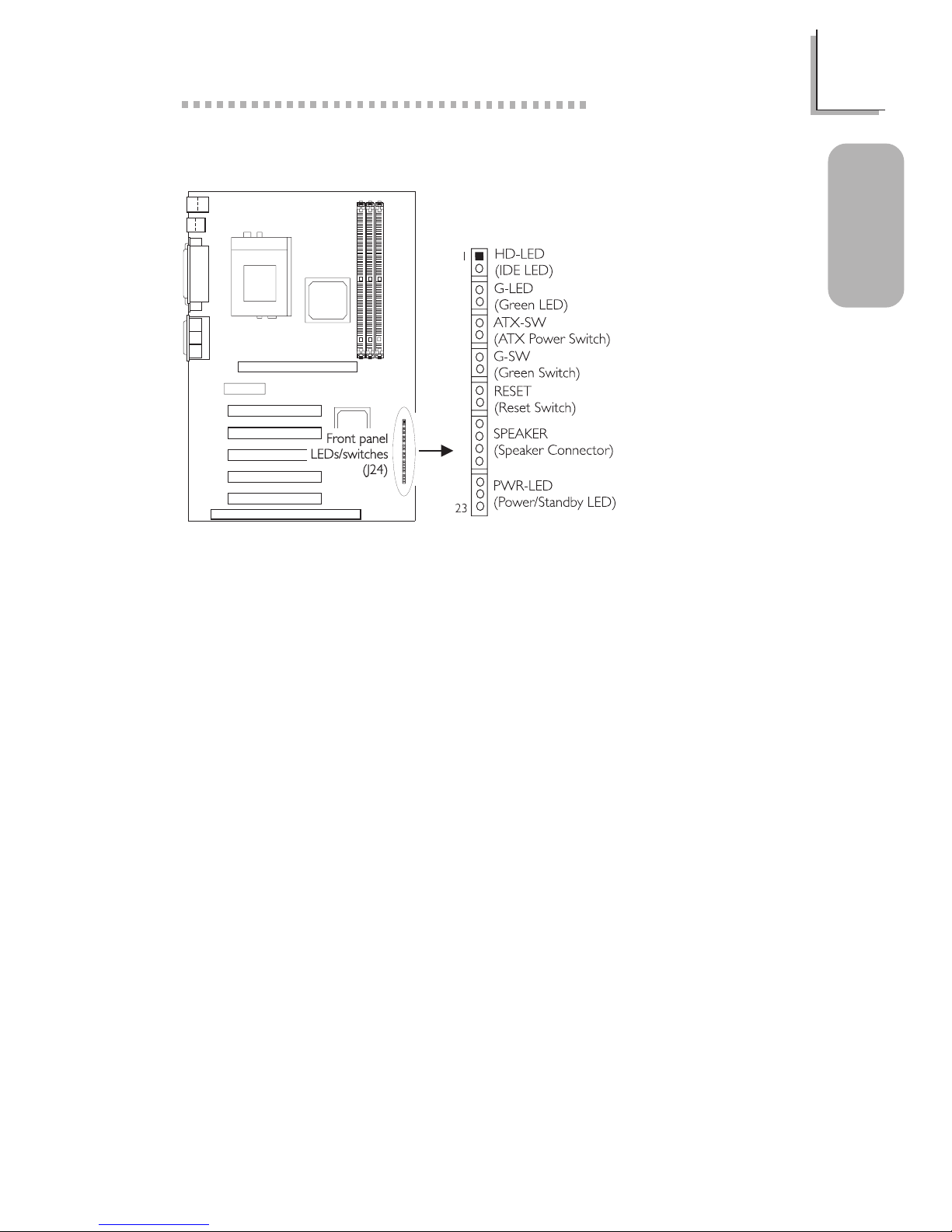
1.3.14 Front Panel LEDs and Switches
1 HDD LED Power
2 HDD
3 N. C.
4 Green LED Power
5 Ground
6 N. C.
7 PWRBT
8 Ground
9 N. C.
10 SMI
11 Ground
12 N. C.
13 H/W Reset
14 Ground
15 N. C.
16 Speaker Data
17 N. C.
18 Ground
19 Speaker Power
20 N. C.
21 LED Power (+)
22 N.C.
23 LED Power (-) or
Standby Signal
When the system is in the S1 (POS - Power On Suspend) state, the
Green LED and Power/Standby LED will blink every second.
When the system is in the S3 (STR - Suspend To RAM) state, the Power/
Standby LED will blink every 4 seconds.
If a system did not boot-up and the Power/Standby LED did not light
after it was powered-on, it may indicate that the CPU or memory module
was not installed properly. Please make sure they are properly inserted
into their corresponding socket.

18
Quick Setup Guide
1
Quick Setup
Guide
1.4 Award BIOS Setup Utility
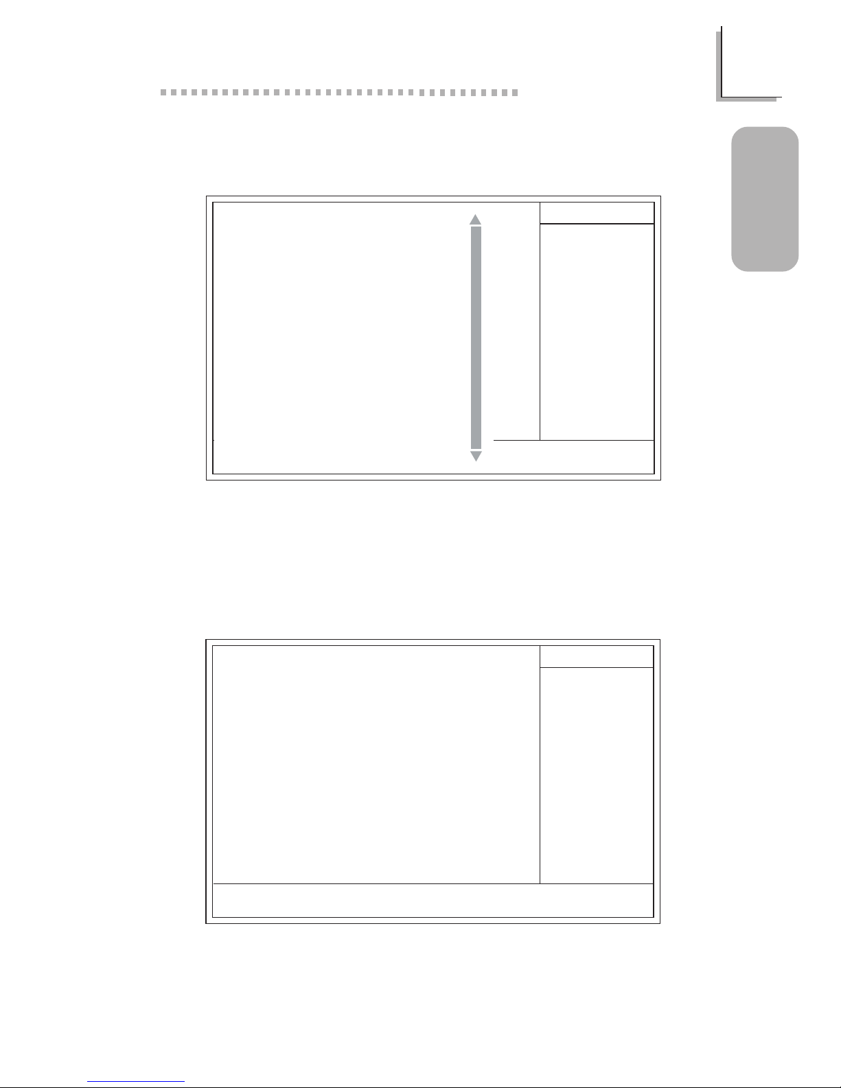
1.4.1 Main Menu
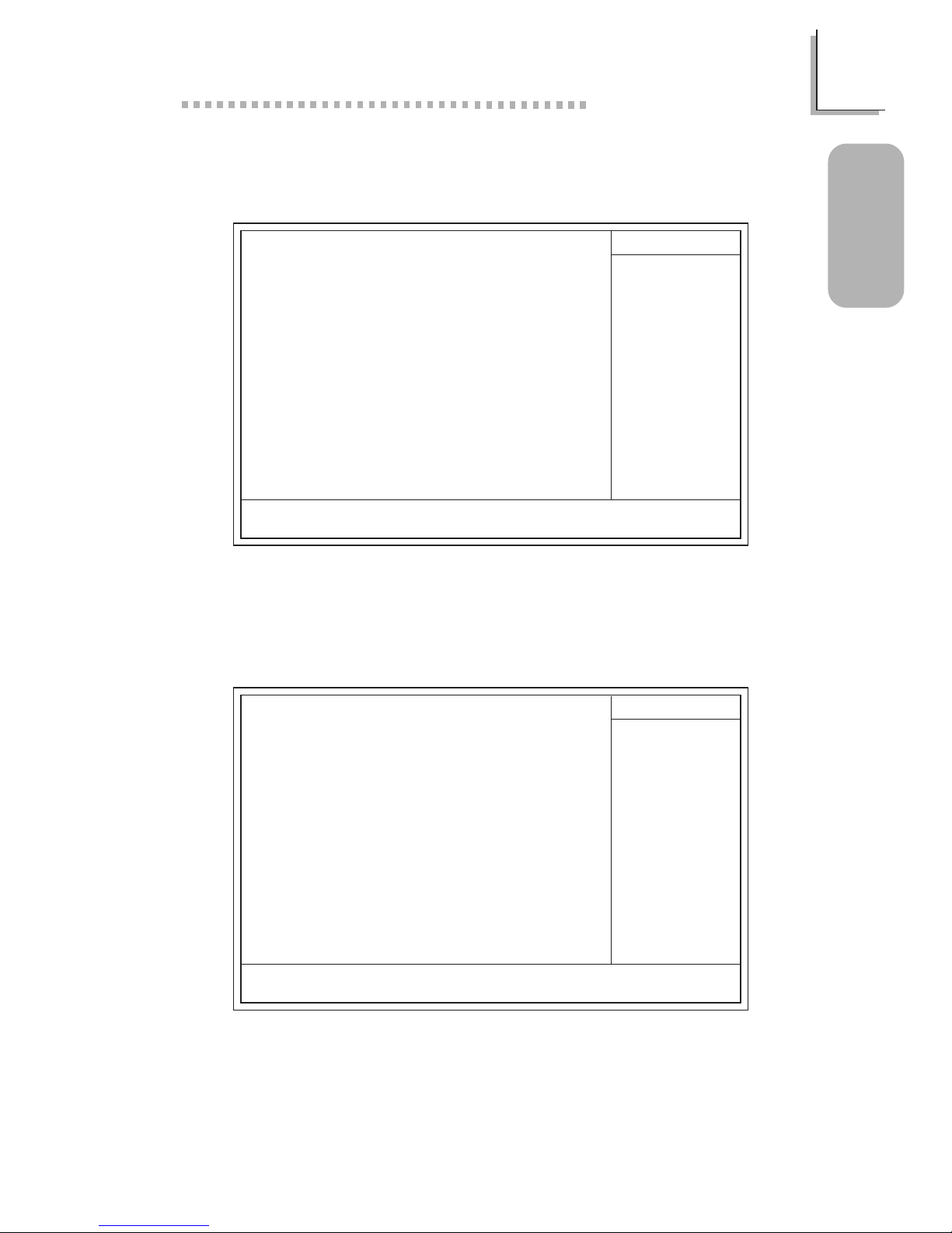
1.4.2 Standard CMOS Features
CMOS Setup Utility - Copyright (C) 1984-2000 Award Software
Standard CMOS Features
Advanced BIOS Features
Advanced Chipset Features
Integrated Peripherals
Power Management Setup
PnP/PCI Configurations
PC Health Status
Frequency/Voltage Control
Load Fail-Safe Defaults
Load Optimized Defaults
Set Supervisor Password
Set User Password
Save & Exit Setup
Exit Without Saving
Esc
F10
: Quit
: Save & Exit Setup
↑↓→←
: Select Item
Time, Date, Hard Disk Type...
The settings on the screen are for reference only. Your version may not be
identical to this one.
↑↓→← Move
CMOS Setup Utility - Copyright (C) 1984-2000 Award Software
Standard CMOS Features
Date (mm:dd:yy)
Time (hh:mm:ss)
IDE Primary Master
IDE Primary Slave
IDE Secondary Master
IDE Secondary Slave
Drive A
Drive B
Video
Halt On
Base Memory
Extended Memory
Total Memory
F6:Fail-Safe Defaults F7:Optimized Defaults
F1:General Help
Tue, May 23 2000
4 : 35 : 5
Press Enter None
Press Enter None
Press Enter None
Press Enter None
1.44M, 3.5 in.
None
EGA/VGA
All Errors
640K
129024K
130048K
Item Help
Menu Level
Change the day, month,
year and century
Enter:Select
F5:Previous Values
+/-/PU/PD:Value F10:Save ESC:Exit
19
1
Quick Setup Guide
Quick Setup
Guide
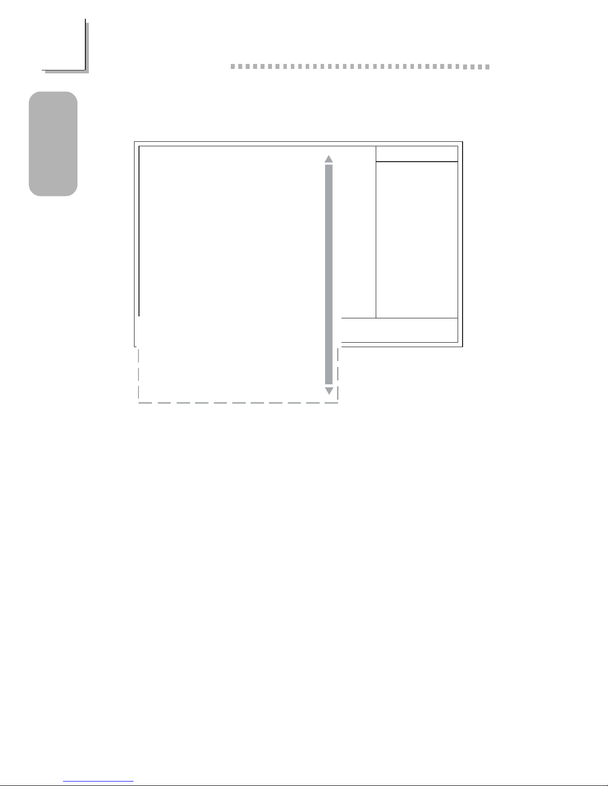
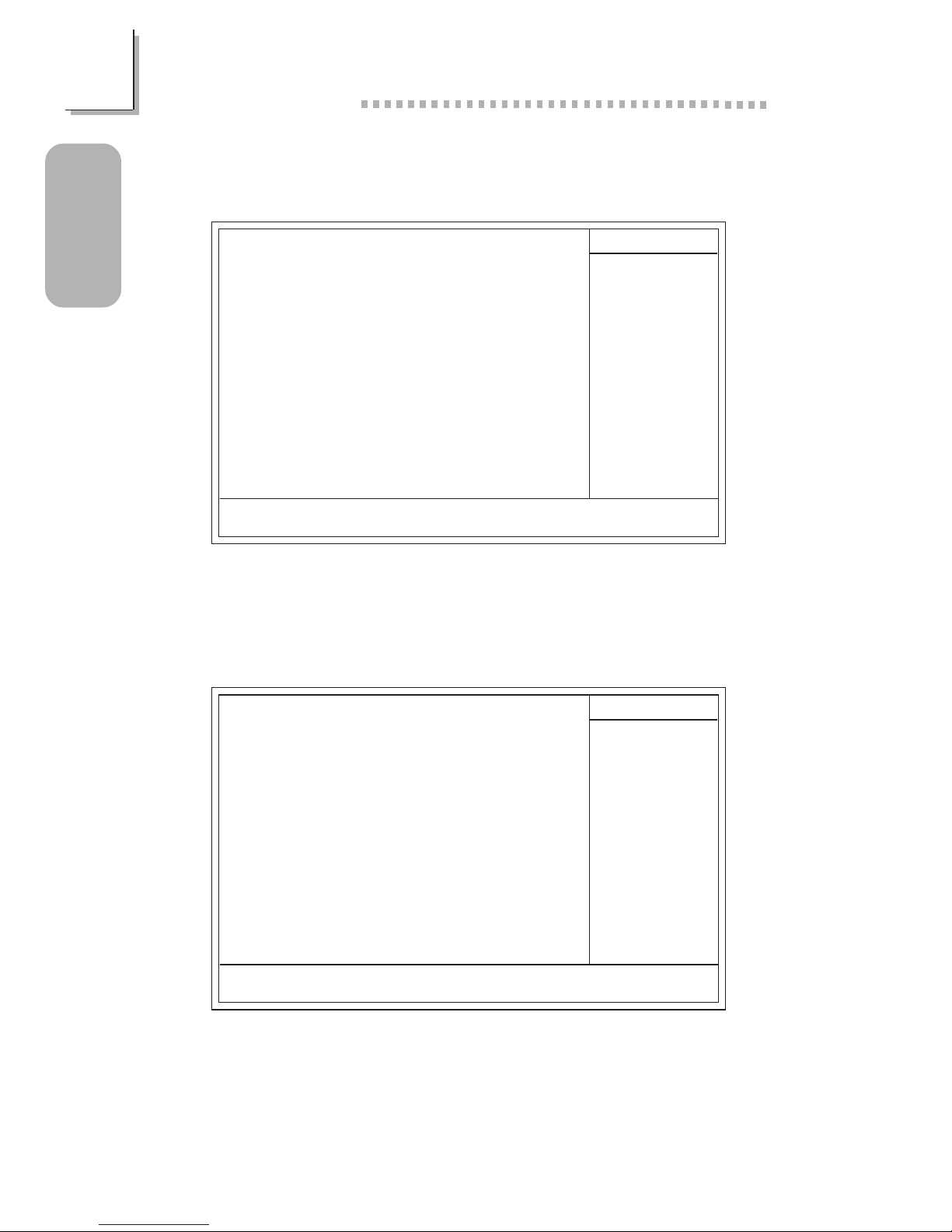
1.4.3 Advanced BIOS Features
1.4.4 Advanced Chipset Features
CMOS Setup Utility - Copyright (C) 1984-2000 Award Software
Advanced BIOS Features
Item Help
Menu Level
Allows you to choose
the VIRUS warning
feature for IDE Hard
Disk boot sector
protection. If this
function is enabled and
someone attempt to
write data into this
area, BIOS will show a
warning message on
screen and alarm beep
↑↓→← Move
F6:Fail-Safe Defaults F7:Optimized Defaults
F1:General HelpEnter:Select
F5:Previous Values
+/-/PU/PD:Value F10:Save ESC:Exit
Virus Warning
CPU Internal Cache
External Cache
CPU L2 Cache ECC Checking
Processor Serial Number
Quick Power On Self Test
First Boot Device
Second Boot Device
Third Boot Device
Boot Other Device
Swap Floppy Drive
Boot Up Floppy Seek
Boot Up NumLock Status
Gate A20 Option
Security Option
OS Select For DRAM > 64MB
Video BIOS Shadow
C8000-CBFFF Shadow
CC000-CFFFF Shadow
D0000-D3FFF Shadow
D4000-D7FFF Shadow
D8000-DBFFF Shadow
DC000-DFFFF Shadow
Disabled
Enabled
Enabled
Enabled
Disabled
Enabled
Floppy
HDD-0
LS120
Enabled
Disabled
Disabled
Off
Fast
Setup
Non-OS2
Enabled
Disabled
Disabled
Disabled
Disabled
Disabled
Disabled
The screen above list all the fields available in the Advanced BIOS Features
submenu, for ease of reference in this manual. In the actual CMOS setup,
you have to use the scroll bar to view the fields. The settings on the screen
are for reference only. Your version may not be identical to this one.
CMOS Setup Utility - Copyright (C) 1984-2000 Award Software
Advanced Chipset Features
Item Help
Menu Level
↑↓→← Move
F6:Fail-Safe Defaults F7:Optimized Defaults
F1:General HelpEnter:Select
F5:Previous Values
+/-/PU/PD:Value F10:Save ESC:Exit
DRAM Timing
SDRAM Cycle Length
Memory Hole
P2C/C2P Concurrency
Fast R-W Turn Around
AGP Aperture Size
AGP Fast Write
OnChip USB
USB Keyboard Support
OnChip Modem
CPU to PCI Write Buffer
PCI Dynamic Bursting
PCI Master 0 WS Write
PCI Delay Transaction
PCI#2 Access #1 Retry
AGP Master 1 WS Write
AGP Master 1 WS Read
Memory Parity/ECC Check
Normal
3
Disabled
Enabled
Disabled
64M
Disabled
Enabled
Disabled
Auto
Enabled
Enabled
Enabled
Enabled
Enabled
Disabled
Disabled
Disabled
The settings on the screen are for reference only. Your version may not be
identical to this one.
20
Quick Setup Guide
1
Quick Setup
Guide
1.4.5 Integrated Peripherals
The screen above list all the fields available in the Integrated Peripherals
submenu, for ease of reference in this manual. In the actual CMOS setup,
you have to use the scroll bar to view the fields. The settings on the screen
are for reference only. Your version may not be identical to this one.
X
X
CMOS Setup Utility - Copyright (C) 1984-2000 Award Software
Integrated Peripherals
Item Help
Menu Level
↑↓→← Move
F6:Fail-Safe Defaults F7:Optimized Defaults
F1:General HelpEnter:Select
F5:Previous Values
+/-/PU/PD:Value F10:Save ESC:Exit
OnChip IDE Channel0
OnChip IDE Channel1
IDE Prefetch Mode
IDE Primary Master PIO
IDE Primary Slave PIO
IDE Secondary Master PIO
IDE Secondary Slave PIO
IDE Primary Master UDMA
IDE Primary Slave UDMA
IDE Secondary Master UDMA
IDE Secondary Slave UDMA
Init Display First
IDE HDD Block Mode
Onboard FDD Controller
Onboard Serial Port 1
Onboard Serial Port 2
UART 2 Mode
IR Function Duplex
TX,RX Inverting Enable
Onboard Parallel Port
Onboard Parallel Mode
ECP Mode Use DMA
Parallel Port EPP Type
Onboard Legacy Audio
Sound Blaster
SB I/O Base Address
SB IRQ Select
SB DMA Select
MPU-401
MPU-401 I/O Address
Game Port (200-207H)
Enabled
Enabled
Enabled
Auto
Auto
Auto
Auto
Auto
Auto
Auto
Auto
PCI Slot
Enabled
Enabled
3F8/IRQ4
2F8/IRQ3
Standard
Half
No, Yes
378/IRQ7
ECP+EPP
3
EPP1.7
Enabled
Disabled
220H
IRQ 5
DMA 1
Disabled
330-333H
Enabled
21
1
Quick Setup Guide
Quick Setup
Guide
1.4.7 PnP/PCI Configurations
1.4.6 Power Management Setup
The settings on the screen are for reference only. Your version may not be
identical to this one.
CMOS Setup Utility - Copyright (C) 1984-2000 Award Software
Power Management Setup
Power Management
ACPI Suspend Type
PM Control by APM
Video Off Option
Video Off Method
MODEM Use IRQ
Soft-Off By PWRBTN
PWR Lost Resume State
Wake Up Events
Press Enter
S1(POS)
Yes
Suspend -> Off
V/H SYNC+Blank
3
Instant-off
Keep Off
Press Enter
Item Help
Menu Level
↑↓→← Move
F6:Fail-Safe Defaults F7:Optimized Defaults
F1:General HelpEnter:Select
F5:Previous Values
+/-/PU/PD:Value F10:Save ESC:Exit
u
u
u
u
The settings on the screen are for reference only. Your version may not be
identical to this one.
X
X
CMOS Setup Utility - Copyright (C) 1984-2000 Award Software
PnP/PCI Configurations
Reset Configuration Data
Resources Controlled By
IRQ Resources
DMA Resources
PCI/VGA Palette Snoop
Assign IRQ For VGA
Assign IRQ For USB
Disabled
Auto(ESCD)
Press Enter
Press Enter
Disabled
Enabled
Enabled
Item Help
Menu Level
Default is Disabled.
Select Enabled to
reset Extended System
Configuration Data
(ESCD) when you exit
Setup if you have
installed a new add-on
and the system
reconfiguration has
caused such a serious
conflict that the OS
cannot boot.
↑↓→← Move
F6:Fail-Safe Defaults F7:Optimized Defaults
F1:General HelpEnter:Select
F5:Previous Values
+/-/PU/PD:Value F10:Save ESC:Exit
22
Quick Setup Guide
1
Quick Setup
Guide
1.4.9 Frequency/Voltage Control
The settings on the screen are for reference only. Your version may not be
identical to this one.
CMOS Setup Utility - Copyright (C) 1984-2000 Award Software
Frequency/Voltage Control
Spread Spectrum
CPU Host/PCI Clock
Disabled
Default
Item Help
Menu Level
↑↓→← Move
F6:Fail-Safe Defaults F7:Optimized Defaults
F1:General HelpEnter:Select
F5:Previous Values
+/-/PU/PD:Value F10:Save ESC:Exit
1.4.8 PC Health Status
The settings on the screen are for reference only. Your version may not be
identical to this one.
CMOS Setup Utility - Copyright (C) 1984-2000 Award Software
PC Health Status
Current CPU Temp.
Current System Temp.
Current CPU Fan Speed
Current Chassis Fan Speed
Vcore
37C/98F
27C/80F
5698 RPM
0 RPM
Item Help
Menu Level
↑↓→← Move
F6:Fail-Safe Defaults F7:Optimized Defaults
F1:General HelpEnter:Select
F5:Previous Values
+/-/PU/PD:Value F10:Save ESC:Exit
2.06 V
1.53 V
3.31 V
5.05 V
12.03 V
2.5V
3.3V
5V
12V

23
2
English
English
Table of Contents
Chapter 2 - English
Package Checklist
The system board package contains the following items:
þ The system board
þ A users manual
þ One IDE cable for ATA/33, ATA/66 or ATA/100 IDE drives
þ One 34-pin floppy disk drive cable
þ One Main Board Utility CD
If any of these items are missing or damaged, please contact your
dealer or sales representative for assistance.
2.1 Features and Specifications.....................................................................................
2.2 Using the Suspend to RAM Function..........................................................
2.3 AGP Pro Slot......................................................................................................................
2.4 Supported Softwares...................................................................................................
2.5 Troubleshooting.................................................................................................................
24
29
31
32
35

24
English
2
English
2.1 Features and Specifications
2.1.1 Features
Chipset
VIA® 82C694X/82C686B AGPset
Processor
The system board is equipped with Socket 370. It is also equipped
with a switching voltage regulator that automatically detects 1.30V
to 3.5V.
Pentium® III FCPGA 133MHz FSB (533EB-1GHz) or 100MHz
FSB (500E-850E) processor
Celeron
TM
66MHz FSB: FCPGA (566MHz-700MHz) or PPGA
(300A-533MHz) processor
Future VIA CyrixIII processor
System Memory
Up to 1GB using VCM (Virtual Channel Memory) or PC
SDRAM DIMM (unbuffered or registered)
Three 168-pin DIMM sockets
Uses x64 or x72 PC SDRAM, 3.3V
- PC-66 SDRAM DIMM for 66MHz FSB processors
- PC-100 SDRAM DIMM for 100/66MHz FSB processors
- PC-133 SDRAM DIMM for 133MHz FSB processors
ECC supported (uses x72 PC SDRAM DIMM)
Note:
If you are using more than one DIMM, make sure you insert
the same type of DIMMs into the DIMM sockets. Using
different types (VCM or PC SDRAM) of DIMMs may cause
problems.

25
2
English
English
DIMMs
2MBx64/x72
4MBx64/x72
8MBx64/x72
Memory Size
16MB
32MB
64MB
DIMMs
16MBx64/x72
32MBx64/x72
64MBx64/x72
Memory Size
128MB
256MB
512MB
Expansion Slots
The system board is equipped with 1 univer sal AGP Pro slot. AGP
Pro is an extension to the existing AGP slot. It delivers additional
electrical power on both ends of the slot to meet the needs of
advanced workstation graphics add-in cards. The universal AGP Pro
slot supports AGP 2x with up to 533MB/sec. bandwidth and AGP
4x with up to 1066MB/sec. bandwidth, allowing you to install either
an AGP add-in card or an AGP Pro add-in card. AGP in this system
board will deliver faster and better graphics to your PC.
The system board is also equipped with 4 dedicated PCI slots, 1
shared PCI/ISA slot and 1 AMR slot. AMR (Audio/Modem Riser) is
an interface designed for installing an audio riser card, modem riser
card or audio/modem riser card that is compliant to the AMR
specification.
Onboard Audio Features
Supports Microsoft® DirectSound/DirectSound 3D
AC97 supported with full duplex, independent sample rate con-
verter for audio recording and playback
ATX Double Deck Ports (PC 99 color-coded connectors)
Two USB ports
Two NS16C550A-compatible DB-9 serial ports
One SPP/ECP/EPP DB-25 parallel port
One mini-DIN-6 PS/2 mouse port
One mini-DIN-6 PS/2 keyboard port
One game/MIDI port
Three audio jacks: line-out, line-in and mic-in
Connectors
One connector for 2 additional external USB ports
One connector for IrDA interface
Two IDE connectors

26
English
2
English
One floppy drive interface supports up to two 2.88MB floppy
drives
One 20-pin ATX power supply connector
One Wake-On-LAN connector
One Wake-On-Ring connector
CPU, chassis and second fan connectors
Three internal audio connectors (AUX-in, CD-in and TAD)
PCI Bus Master IDE Controller
Two PCI IDE interfaces support up to four IDE devices
Supports ATA/33, ATA/66 and ATA/100 hard drives
PIO Mode 3 and Mode 4 Enhanced IDE (data transfer rate up
to 16.6MB/sec.)
Bus mastering reduces CPU utilization during disk transfer
Supports ATAPI CD-ROM, LS-120 and ZIP
IrDA Interface
The system board is equipped with an IrDA connector for wireless
connectivity between your computer and peripheral devices. It
supports peripheral devices that meet the HPSIR and ASKIR
standard.
USB Ports
The system board supports 4 USB por ts. Two onboard USB ports
are located at the ATX double deck por ts of the board. The J18
connector on the system board allows you to connect the optional
3rd and 4th USB ports. These optional USB por ts, which are
mounted on a card-edge bracket, will be provided as an option.
USB allows data exchange between your computer and a wide
range of simultaneously accessible external Plug and Play peripherals.
BIOS
Award BIOS, Windows® 95/98/2000 Plug and Play compatible
Supports SCSI sequential boot-up
Flash EPROM for easy BIOS upgrades
Supports DMI 2.0 function
2Mbit flash memory

27
2
English
English
Desktop Management Interface (DMI)
The system board comes with a DMI 2.0 built into the BIOS. The
DMI utility in the BIOS automatically records various information
about your system configuration and stores these information in the
DMI pool, which is a part of the system board's Plug and Play
BIOS. DMI, along with the appropriately networked software, is
designed to make inventory, maintenance and troubleshooting of
computer systems easier.
2.1.2 System Health Monitor Functions
The system board is capable of monitoring the following system
health conditions.
Monitors CPU/system temperature and overheat alarm
Monitors VCORE/3.3V/5V/12V/2.5V voltages and failure alarm
Monitors CPU/chassis fan speed and failure alarm
Automatic CPU and chassis fans on/off control
Read back capability that displays temperature, voltage and fan
speed
If you want a warning message to pop-up or a warning alarm to
sound when an abnormal condition occurs, you must install the VIA
Hardware Monitor utility. This utility is included in the CD that came
with the system board.
2.1.3 Intelligence
Automatic CPU/Chassis Fan Off
The CPU and chassis fans will automatically turn off once the system
enters the Suspend mode.
Dual Function Power Button
Depending on the setting in the Soft-Off By PWRBTN field of the
Power Management Setup, this switch will allow the system to enter
the Soft-Off or Suspend mode.

28
English
2
English
Wake-On-Ring
This feature allows the system that is in the Suspend mode or Soft
Power Off mode to wake-up/power-on to respond to calls coming
through an internal or external modem.
Important:
If you are using a modem add-in card, the 5VSB power source
of your power supply must support a minimum of ≥720mA.
RTC Timer to Power-on the System
The RTC installed on the system board allows your system to
automatically power-on on the set date and time.
Wake-On-LAN
The Wake-On-LAN function allows the network to remotely wake
up a Soft Power Down (Soft-Off) PC. Your LAN card must support
the remote wakeup function.
Important:
The 5VSB power source of your power supply must support a
minimum of ≥720mA.
AC Power Failure Recovery
When power returns after an AC power failure, you may choose to
either power-on the system manually, let the system power-on
automatically or return to the state where you left off before power
failure occurs.
ACPI STR
The system board is designed to meet the ACPI (Advanced
Configuration and Power Interface) specification. ACPI has energy
saving features that enables PCs to implement Power Management
and Plug-and-Play with operating systems that support OS Direct
Power Management. Currently, only Windows® 98/2000 supports
the ACPI function allowing you to use the Suspend to RAM function.
With the Suspend to RAM function enabled, you can power-off the
system at once by pressing the power button or selecting Standby
when you shut down Windows® 98/2000 without having to go
 Loading...