

DFI CA34-SC, CA34-SU User Manual

CA34-SC
CA34-SU
Rev. A+
System Board
Users Manual
42300023

Copyright
This publication contains information that is protected by copyright.
No part of it may be reproduced in any form or by any means or
used to make any transformation/adaptation without the prior
written permission from the copyright holders.
This publication is provided for informational purposes only. The
manufacturer makes no representations or warranties with respect to
the contents or use of this manual and specifically disclaims any
express or implied warranties of merchantability or fitness for any
particular purpose. The user will assume the entire risk of the use or
the results of the use of this document. Further, the manufacturer
reserves the right to revise this publication and make changes to its
contents at any time, without obligation to notify any person or
entity of such revisions or changes.
© 2000. All Rights Reserved.
Trademarks
Microsoft® MS-DOS®, WindowsTM, Windows® 95, Windows® 98 and
Windows® 2000 are registered trademarks of Microsoft
Corporation. Intel®, Pentium® III and CeleronTM are registered
trademarks of Intel Corporation. VIA CyrixIII is a registered
trademark of VIA Technologies, Inc. Award is a registered trademark
of Award Software, Inc. Other trademarks and registered
trademarks of products appearing in this manual are the properties
of their respective holders.
Caution:
Danger of explosion if battery incorrectly replaced.
Replace only with the same or equivalent type recommended by the
manufacturer.
Dispose of used batteries according to the battery manufacturers
instructions.

FCC and DOC Statement on Class B
This equipment has been tested and found to comply with the limits
for a Class B digital device, pursuant to Part 15 of the FCC rules.
These limits are designed to provide reasonable protection against
harmful interference when the equipment is operated in a residential
installation. This equipment generates, uses and can radiate radio
frequency energy and, if not installed and used in accordance with
the instruction manual, may cause harmful interference to radio
communications. However, there is no guarantee that interference
will not occur in a particular installation. If this equipment does cause
harmful interference to radio or television reception, which can be
determined by turning the equipment off and on, the user is
encouraged to try to correct the interference by one or more of the
following measures:
Reorient or relocate the receiving antenna.
Increase the separation between the equipment and the receiver.
Connect the equipment into an outlet on a circuit different from
that to which the receiver is connected.
Consult the dealer or an experienced radio TV technician for
help.
Notice:
1. The changes or modifications not expressly approved by the
party responsible for compliance could void the user's authority
to operate the equipment.
2. Shielded interface cables must be used in order to comply with
the emission limits.

Table of Contents
Read Me First..........................................................
Chapter 1 - Introduction
1.1 Features and Specifications..................................................................................
1.2 Package Checklist.........................................................................................................
Chapter 2 - Hardware Installation
2.1 System Board Layout .............................................................................................
2.2 System Memory.............................................................................................................
2.3 Frequency Ratio Settings for Processors................................................
2.4 Jumper Settings for Selecting the CPU Type...............................................
2.5 Jumper Settings for Selecting the CPUs Front Side Bus...............
2.6 Jumper Settings for Clearing CMOS Data..........................................
2.7 Jumper Settings for the Onboard Audio Codec...........................
2.8 Jumper Settings for the Onboard PCI Audio...................................
2.9 Factory Use Jumper...................................................................................................
2.10 Ports and Connectors.............................................................................................
Chapter 3 - Award BIOS Setup Utility
3.1 The Basic Input/Output System.....................................................................
3.1.1 Standard CMOS Features.............................................................
3.1.2 Advanced BIOS Features..............................................................
3.1.3 Advanced Chipset Features ......................................................
3.1.4 Integrated Peripherals.........................................................................
3.1.5 Power Management Setup............................................................
3.1.6 PnP/PCI Configurations....................................................................
3.1.7 PC Health Status...................................................................................
3.1.8 Frequency/Voltage Control............................................................
3.1.9 Load Fail-Safe Defaults.....................................................................
3.1.10 Load Optimized Defaults..............................................................
3.1.11 Set Supervisor Password...............................................................
3.1.12 Set User Password..............................................................................
3.1.13 Save & Exit Setup.................................................................................
3.1.14 Exit Without Saving..............................................................................
7
13
43
43
47
51
56
61
66
69
70
71
72
72
73
73
73
14
16
18
20
21
22
23
24
25
26
6

Chapter 4 - Supported Softwares
4.1 Desktop Management Interface.....................................................................
4.2 VIA Hardware Monitor............................................................................................
4.3 VIA Service Pack..........................................................................................................
4.4 Audio Drivers and Software Application...............................................
4.5 Drivers and Utilities Installation Notes.....................................................
Appendix A - Using the Suspend to RAM
Function
A.1 Using the Suspend to RAM Function........................................................
Appendix B - System Error Messages
B.1 POST Beep.......................................................................................................................
B.2 Error Messages..............................................................................................................
Appendix C - Troubleshooting
C.1 Troubleshooting Checklist....................................................................................
74
77
77
78
79
84
84
80
86

Introduction
1
6
Read Me First
This page contains a summary of the important notes that must be
given special attention to prior to using the system board.
Processor
The frequency ratio of some processors may have been locked
by the manufacturer. If you are using this kind of processor,
setting an extended ratio for the processor will have no effect.
The system will instead use its factory default ratio.
The frequency ratio of processors greater than 8x has been
locked by the manufacturer and will no longer have the flexibility
of using extended ratios. Therefore, the system will use the
processors factory default ratio.
Selecting an external bus clock other than 66MHz, 100MHz or
133MHz may result to the processors or systems instability and
are not guaranteed to provide better system performance.
System Memory
The system board supports both VCM and PC SDRAM DIMMs. If
you are using more than one DIMM, make sure you insert the same
type of DIMMs into the DIMM sockets. Using different types (VCM
or PC SDRAM) of DIMMs may cause problems.
5VSB Power
If you are using the (1) Wake-On-LAN and/or (2) Wake-On-
Ring (internal modem) functions, the 5VSB power source of your
power supply must support ≥720mA.
If you are using the Suspend to RAM function, the 5VSB power
source of your power supply must support ≥1A.
Drivers
Make sure to reboot the system after each driver installation.
Problems will occur if you reboot only after installing all the drivers.

1
Introduction
7
1.1 Features and Specifications
1.1.1 Features
Chipset
VIA® 82C694X/82C686A AGPset
Processor
The system board is equipped with Socket 370. It is also equipped
with a switching voltage regulator that automatically detects 1.30V
to 3.5V.
Pentium® III FCPGA 133MHz FSB (533EB-933EB) or 100MHz
FSB (500E-850E) processor
Celeron
TM
66MHz FSB: FCPGA (566MHz-700MHz) or PPGA
(300A-533MHz) processor
Future VIA CyrixIII processor
System Memory
16MB to 512MB using VCM (Virtual Channel Memory) or PC
SDRAM DIMM (unbuffered or registered)
Two 168-pin DIMM sockets
Uses x64 or x72 PC SDRAM, 3.3V
- PC-66 SDRAM DIMM for 66MHz FSB processors
- PC-100 SDRAM DIMM for 100/66MHz FSB processors
- PC-133 SDRAM DIMM for 133MHz FSB processors
ECC supported (uses x72 PC SDRAM DIMM)
Chapter 1 - Introduction
Note:
If you are using more than one DIMM, make sure you insert
the same type of DIMMs into the DIMM sockets. Using
different types (VCM or PC SDRAM) of DIMMs may cause
problems.

Introduction
1
8
Expansion Slots
The system board is equipped with 1 universal AGP slot. AGP is an
interface designed to support high performance 3D graphics cards. It
utilizes a dedicated pipeline to access system memory for texturing,
z-buffering and alpha blending. The universal AGP slot supports AGP
2x with up to 533MB/sec. bandwidth and AGP 4x with up to
1066MB/sec. bandwidth for 3D graphics applications. AGP in this
system board will deliver faster and better graphics to your PC.
The system board is also equipped with 2 dedicated PCI slots and
1 shared AMR/ISA slot. AMR (Audio/Modem Riser) is an interface
designed for installing an audio riser card, modem riser card or
audio/modem riser card that is compliant to the AMR specification.
Onboard Audio Features (CA34-SC only)
Supports Microsoft® DirectSound/DirectSound 3D
AC97 supported with full duplex, independent sample rate con-
verter for audio recording and playback
Onboard PCI Audio Features - Creative ES1373 (CA34-SU only)
Supports Microsoft® DirectSound /DirectSound 3D / DirectMusic
SW acceleration
64 voice wavetable synthesizer
Hardware SoundBlaster Pro for Windows DOS Box and
standard Microsoft Windows Sound 2.0
Digital I/O compatible with consumer mode (SPDIF)
Downloadable sound (DLS) level-1
ATX Double Deck Ports (PC 99 color-coded connectors)
2 USB ports
2 DB-9 serial ports
1 DB-25 parallel port
1 mini-DIN-6 PS/2 mouse port
1 mini-DIN-6 PS/2 keyboard port
DIMMs
2MBx64/x72
4MBx64/x72
8MBx64/x72
Memory Size
16MB
32MB
64MB
DIMMs
16MBx64/x72
32MBx64/x72
Memory Size
128MB
256MB

1
Introduction
9
1 game/MIDI port
3 audio jacks: line-out, line-in and mic-in
Connectors
1 connector for 2 additional external USB ports
1 connector for IrDA interface
2 IDE connectors
1 floppy connector
1 20-pin ATX power supply connector
1 Wake-On-LAN connector
1 Wake-On-Ring connector
3 connectors for CPU, chassis and AGP fans
4 internal audio connectors (video-in, AUX-in, CD-in and TAD)
PCI Bus Master IDE Controller
Two PCI IDE interfaces support up to four IDE devices
Supports ATA/33 or ATA/66 hard drives
PIO Mode 3 and Mode 4 Enhanced IDE (data transfer rate up
to 16.6MB/sec.)
Bus mastering reduces CPU utilization during disk transfer
Supports ATAPI CD-ROM, LS-120 and ZIP
IrDA Interface
The system board is equipped with an IrDA connector for wireless
connectivity between your computer and peripheral devices. It
supports peripheral devices that meet the HPSIR or ASKIR standard.
USB Ports
The system board supports 4 USB por ts. Two onboard USB ports
are located at the ATX double deck ports of the board. The USB 2
connector on the system board allows you to connect the optional
3rd and 4th USB ports. These optional USB ports, which are
mounted on a card-edge bracket, will be provided as an option.
USB allows data exchange between your computer and a wide
range of simultaneously accessible external Plug and Play peripherals.

Introduction
1
10
BIOS
Award BIOS, Windows® 95/98/2000 Plug and Play compatible
Supports SCSI sequential boot-up
Flash EPROM for easy BIOS upgrades
Supports DMI 2.0 function
2Mbit flash memory
Desktop Management Interface (DMI)
The system board comes with a DMI 2.0 built into the BIOS. The
DMI utility in the BIOS automatically records various information
about your system configuration and stores these information in the
DMI pool, which is a part of the system board's Plug and Play
BIOS. DMI, along with the appropriately networked software, is
designed to make inventory, maintenance and troubleshooting of
computer systems easier. Refer to chapter 4 for instructions on using
the DMI utility.
1.1.2 System Health Monitor Functions
The system board is capable of monitoring the following system
health conditions.
Monitors CPU/system temperature and overheat alarm
Monitors VCORE/3.3V/5V/±12V/2.5V voltages and failure alarm
Monitors CPU/chassis fan speed and failure alarm
Fan on/off control includes CPU fan and chassis fan - this pre-
vents system overheat and prolongs fan life
Read back capability that displays temperature, voltage and fan
speed
Refer to PC Health Status in chapter 3 and VIA Hardware
Monitor in chapter 4 for more information.
1.1.3 Intelligence
Automatic CPU/Chassis Fan Off
The CPU and chassis fans will automatically turn off once the system
enters the Suspend mode.

1
Introduction
11
Dual Function Power Button
Depending on the setting in the Soft-Off By PWRBTN field of the
Power Management Setup, this switch will allow the system to enter
the Soft-Off or Suspend mode.
Wake-On-Ring
This feature allows the system that is in the Suspend mode or Soft
Power Off mode to wake-up/power-on to respond to calls coming
through an internal or external modem. Refer to Wake-On-Ring
Connector in chapter 2 and Resume On LAN/Ring (Wake Up
Events field) in the Power Management Setup section in chapter 3
for more information.
Important:
If you are using a modem add-in card, the 5VSB power source
of your power supply must support a minimum of ≥720mA.
RTC Timer to Power-on the System
The RTC installed on the system board allows your system to
automatically power-on on the set date and time. Refer to Resume
On Alarm (Wake Up Events field) in the Power Management
Setup section in chapter 3 for more information.
Wake-On-LAN
The Wake-On-LAN function allows the network to remotely wake
up a Soft Power Down (Soft-Off) PC. Your LAN card must support
the remote wakeup function. Refer to Wake-On-LAN Connector in
chapter 2 and Resume On LAN/Ring (Wake Up Events field) in
the Power Management Setup section in chapter 3 for more
information.
Important:
The 5VSB power source of your power supply must support a
minimum of ≥720mA.

Introduction
1
12
AC Power Failure Recovery
When power returns after an AC power failure, you may choose to
either power-on the system manually, let the system power-on
automatically or return to the state where you left off before power
failure occurs. Refer to PWR Lost Resume State in the Power
Management Setup section in chapter 3 for more information.
ACPI STR
The system board is designed to meet the ACPI (Advanced
Configuration and Power Interface) specification. ACPI has energy
saving features that enables PCs to implement Power Management
and Plug-and-Play with operating systems that support OS Direct
Power Management. Currently, only Windows® 98/2000 supports
the ACPI function. ACPI when enabled in the Power Management
Setup will allow you to use the Suspend to RAM function.
With the Suspend to RAM function enabled, you can power-off
the system at once by pressing the power button or selecting
Standby when you shut down Windows® 98/2000 without having
to go through the sometimes tiresome process of closing files,
applications and operating system. This is because the system is
capable of storing all programs and data files during the entire
operating session into RAM (Random Access Memory) when it
powers-off. The operating session will resume exactly where you left
off the next time you power-on the system. Refer to Using the
Suspend to RAM Function in appendix A for more information.
Important:
The 5VSB power source of your power supply must support a
minimum of ≥1A.
Virus Protection
Most viruses today destroy data stored in hard drives. The system
board is designed to protect the boot sector and partition table of
your hard disk drive.

1
Introduction
13
1.2 Package Checklist
The system board package contains the following items:
þ The system board
þ A users manual
þ One IDE cable for ATA/33 or ATA/66 IDE drives
þ One 34-pin floppy disk drive cable
þ One Main Board Utility CD
If any of these items are missing or damaged, please contact your
dealer or sales representative for assistance.
2
14
Hardware Installation
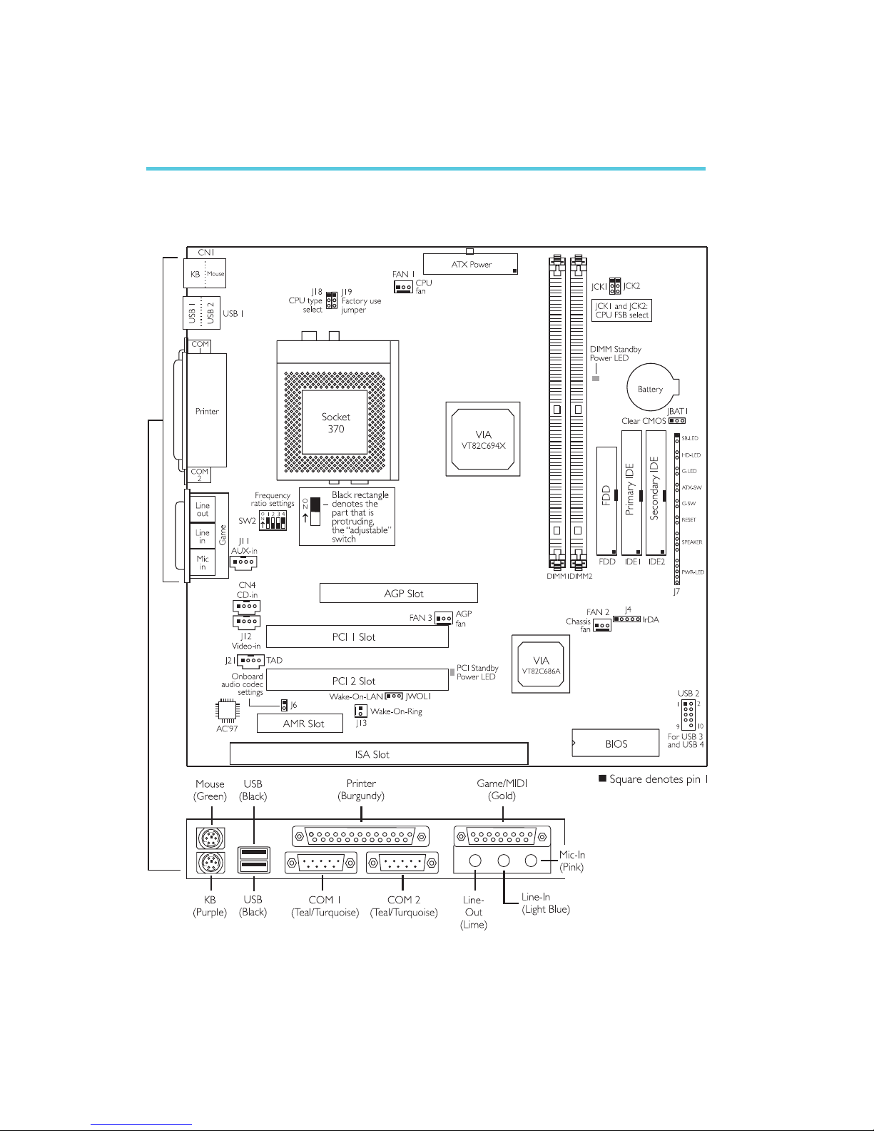
2.1 System Board Layout
Chapter 2 - Hardware Installation
CA34-SC
2
Hardware Installation
15
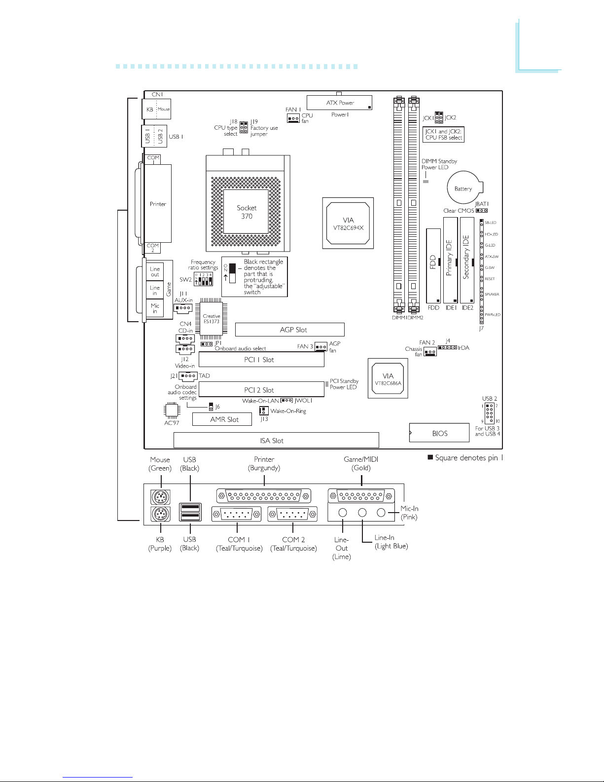
CA34-SU
2
16
Hardware Installation
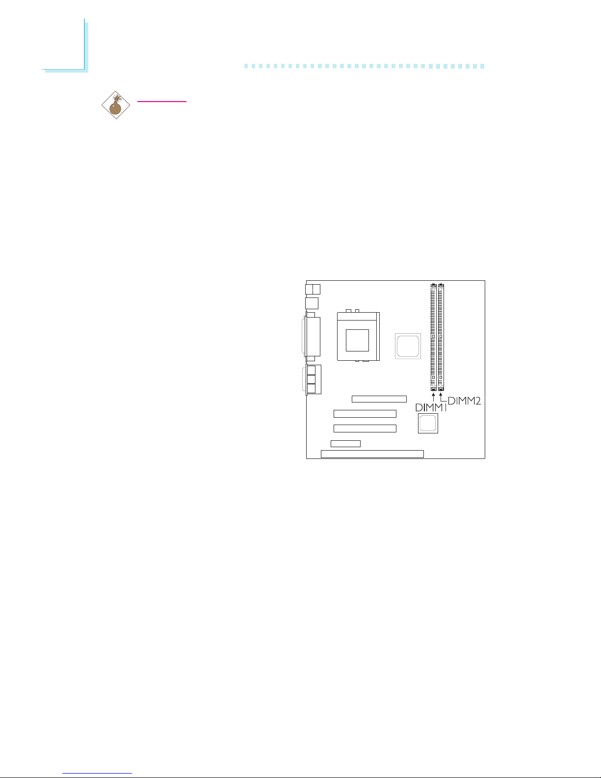
2.2 System Memory
The system board is
equipped with two 168-pin
DIMM (Dual In-line Memory
Module) sockets that support
VCM or PC SDRAM DIMM.
PC SDRAM (Synchronous
Dynamic Random Access
Memory) is a fast memory
interface technology that uses
the clock on the chip to
synchronize with the CPU
clock so that the timing of the
memory chips and the timing of the CPU are synchronized. This
saves time during transmission of data, subsequently increasing
system performance.
The system board also supports the ECC (Error Checking and
Correction) function. To use this function, you must install DIMM that
supports parity. Refer to chapter 1 (System Memory section) for
detailed specification of the memory supported by the system
board.
Warning:
Electrostatic discharge (ESD) can damage your system board,
processor, disk drives, add-in boards, and other components. Perform
the upgrade instruction procedures described at an ESD workstation
only. If such a station is not available, you can provide some ESD
protection by wearing an antistatic wrist strap and attaching it to a
metal part of the system chassis. If a wrist strap is unavailable,
establish and maintain contact with the system chassis throughout
any procedures requiring ESD protection.

2
Hardware Installation
17
1. Pull the tabs which are at the ends of the socket to the side.
2. Position the DIMM above the socket with the notches in the
module aligned with the keys on the socket.
3. Seat the module vertically into the socket. Make sure it is
completely seated. The tabs will hold the DIMM in place.
Pin 1
Notch
Key
Tab
Tab
2.2.1 Installing the DIM Module
A DIM module simply snaps into a DIMM socket on the system
board. Pin 1 of the DIM module must correspond with Pin 1 of the
socket.
2
18
Hardware Installation
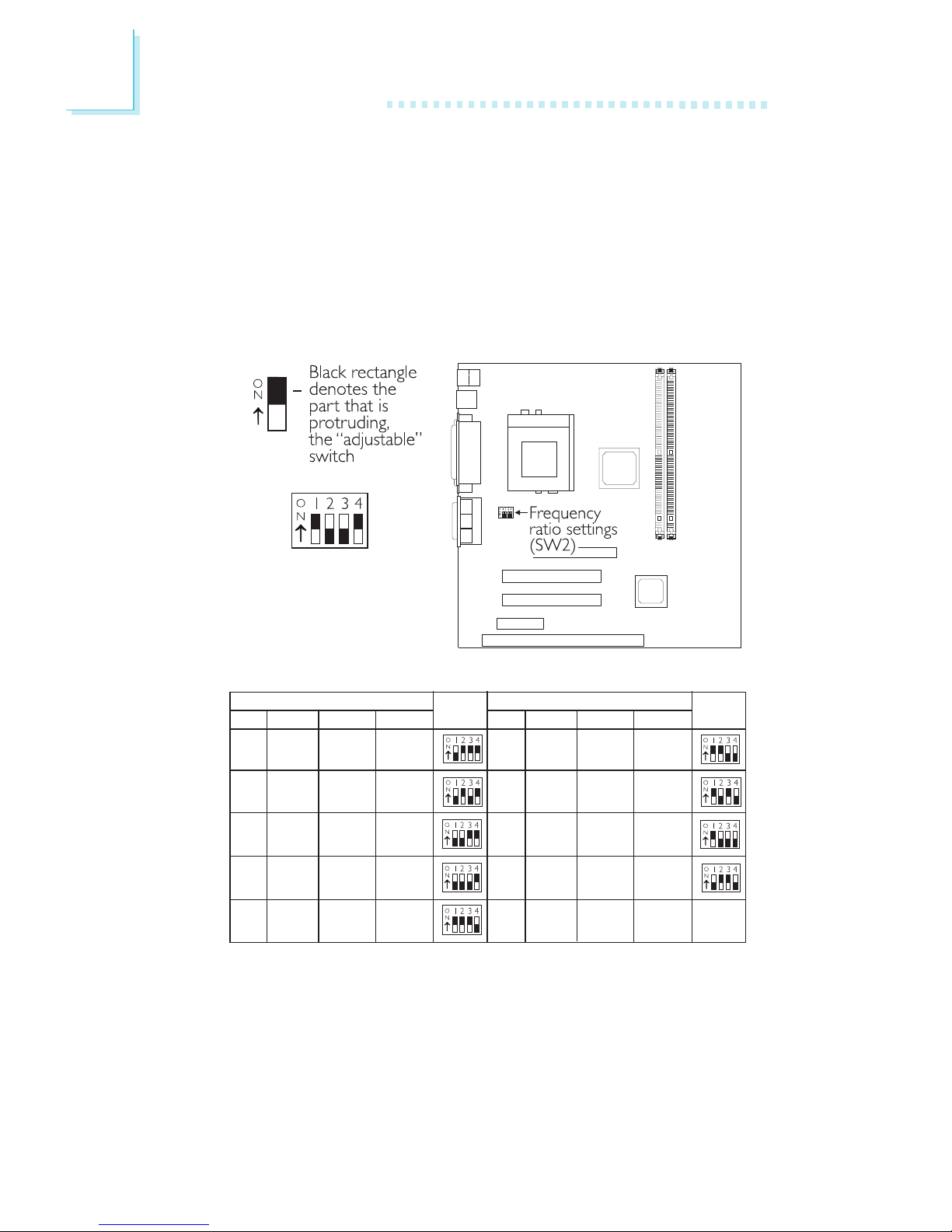
In the example above:
Switch 1: On
Switch 2: Off
Switch 3: Off
Switch 4: On
2.3 Frequency Ratio Settings for Processors
The following table shows the available frequency ratios and their
corresponding DIP switch setting. There are 4 switches on SW2. The
black rectangle in the diagram denotes the part that is protruding,
the adjustable switch. Make sure SW2 is set correctly before
applying power, otherwise you will not be able to power-on the
system.
Processor
SW2
Ratio
66MHz 100MHz 133MHz
4x
--- --- 533MHz
4.5x 300MHz
--- 600MHz
5x 333MHz 500MHz 667MHz
5.5x
366MHz 550MHz 733MHz
Processor
SW2
Ratio 66MHz 100MHz 133MHz
6x
400MHz 600MHz
800MHz
6.5x 433MHz 650MHz 866MHz
7x 466MHz 700MHz 933MHz*
7.5x 500MHz 750MHz 1GHz*
8x
533MHz 800MHz
1.067GHz*

2
Hardware Installation
19
Important:
The frequency ratio of some processors shown in the table
may have been locked by the manufacturer. If you are using
this kind of processor, setting an extended ratio for the
processor will have no effect. The system will instead use its
factory default ratio.
The frequency ratio of processors greater than 8x has been
locked by the manufacturer and will no longer have the
flexibility of using extended ratios. Therefore, the system will
use the processors factory default ratio.
At the time this document was printed, the CPUs marked
with asterisk (*) are not yet available. They are included in
the table for reference only.
The processors supported by the system board support
VID (Voltage Identification). The switching voltage regulator
on the system board will automatically set the voltage
regulator according to the voltage of the processor.

2
20
Hardware Installation
2.4 Jumper Settings for Selecting the CPU Type
CPU Type Select - Jumper J18
This jumper is used to select
the type of processor
installed on the system
board.
1-2 On: Reserved for
Factory Use
1
2
3
1
2
3
2-3 On: Intel® CPU
(default)
2
Hardware Installation
21
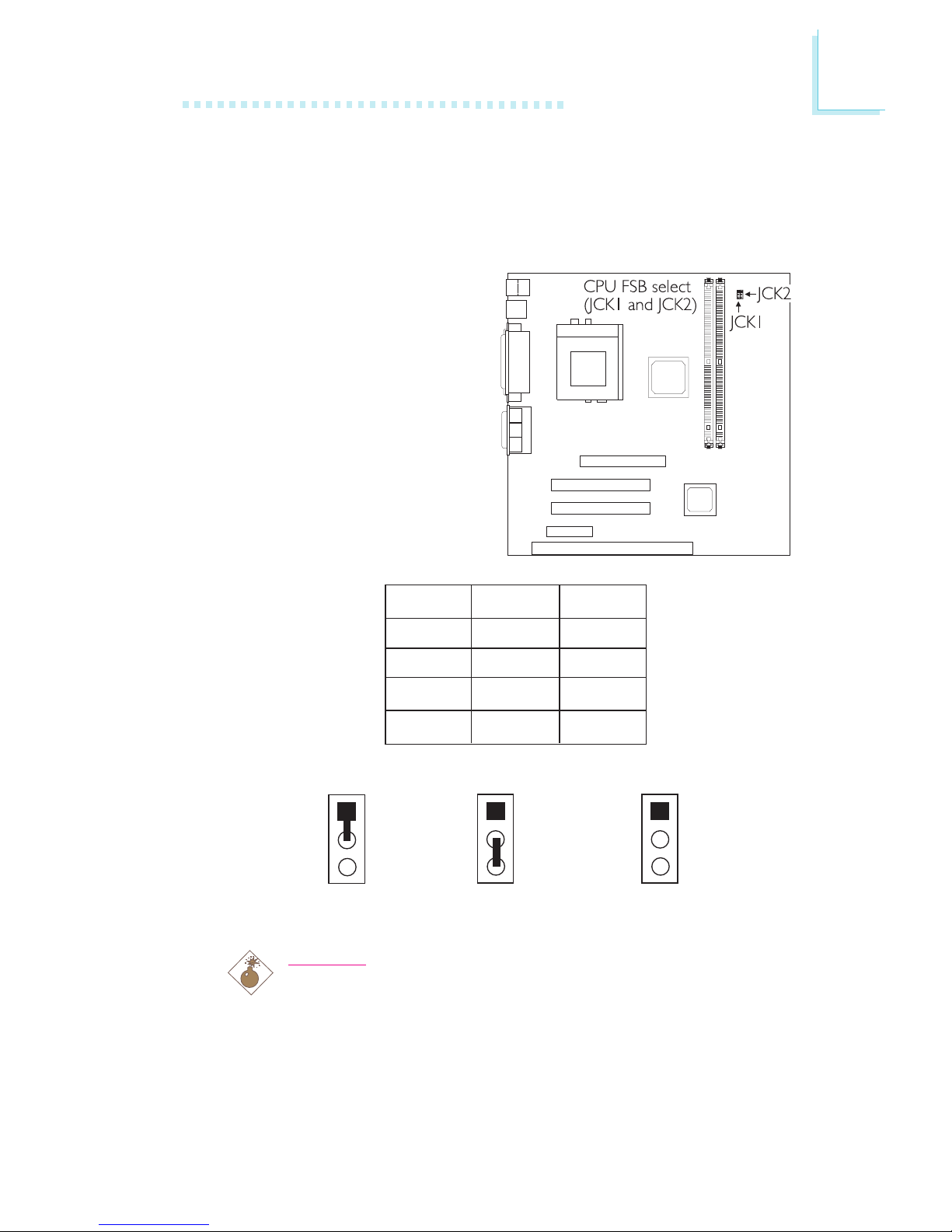
2.5 Jumper Settings for Selecting the CPUs Front
Side Bus
CPU Front Side Bus Select - Jumpers JCK1 and JCK2
These jumpers are used to
select the front side bus of
the processor installed on the
system board. The default
setting is Auto - the system
will automatically run
according to the FSB of the
processor.
Warning:
Some processors, when overclocked, may result to the
processors or systems instability and are not guaranteed to
provide better system performance. If you are unable to boot
your system due to overclocking, make sure to set these
jumpers back to their default settings.
2-3 On1-2 On
All Off
1
2
3
1
2
3
1
2
3
JCK1
1-2 On
2-3 On
All Off
1-2 On
JCK2
1-2 On
2-3 On
2-3 On
All Off
Auto*
66MHz
100MHz
133MHz
* denotes default setting
2
22
Hardware Installation
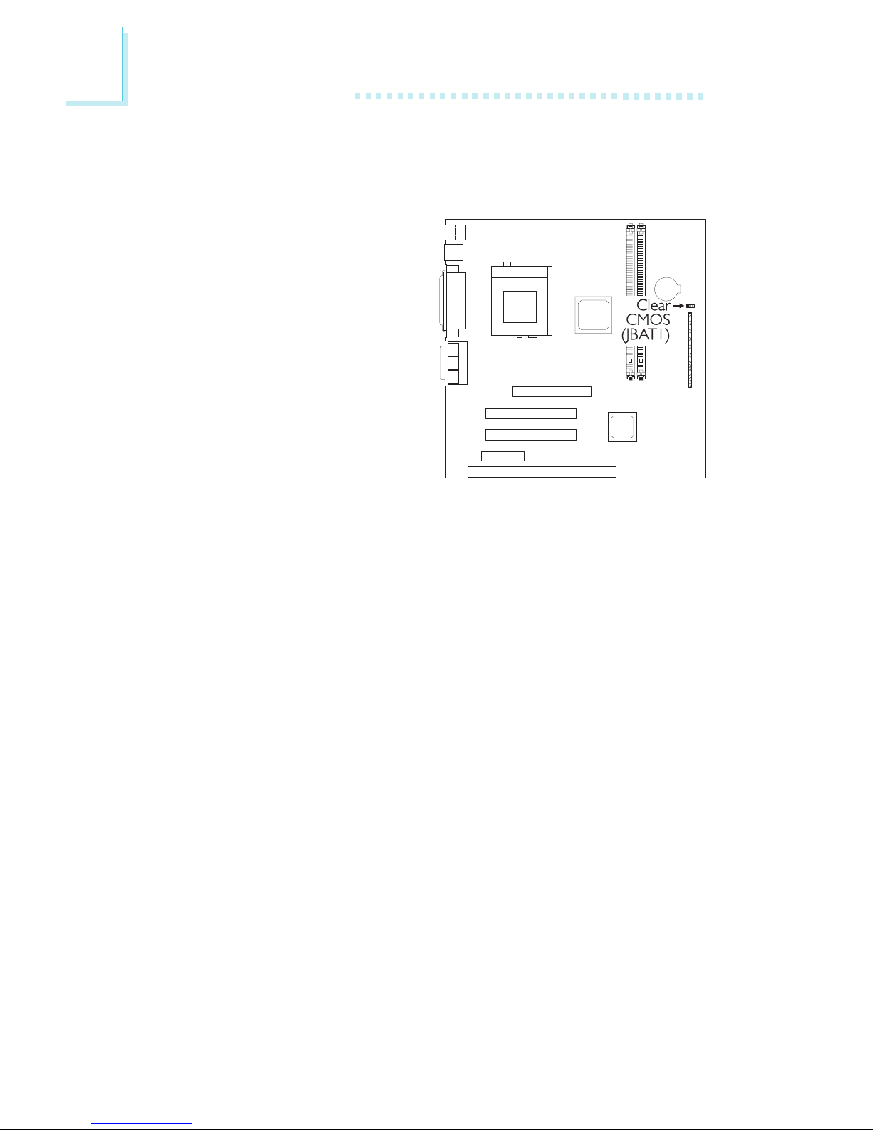
2.6 Jumper Settings for Clearing CMOS Data
Clear CMOS Data - Jumper JBAT1
If you encounter the following,
a) CMOS data becomes
corrupted.
b) You forgot the supervisor
or user password.
c) You are unable to boot-up
the computer system
because the processors
bus clock was incorrectly
set in the BIOS.
you can reconfigure the
system with the default values stored in the ROM BIOS.
To load the default values stored in the ROM BIOS, please follow
the steps below.
1. Power-off the system and unplug the power cord.
2. Set JBAT1 pins 2 and 3 to On. Wait for a few seconds and set
JBAT1 back to its default setting, pins 1 and 2 On.
3. Now plug the power cord and power-on the system.
If your reason for clearing the CMOS data is due to incorrect
setting of the processors bus clock in the BIOS, please proceed
to step 4.
4. After powering-on the system, press <Del> to enter the main
menu of the BIOS.
5. Select the Frequency/Voltage Control submenu and press
<Enter>.
6. Set the CPU Host Clock (CPU/PCI) field to its default setting
or an appropriate bus clock. Refer to CPU Host Clock (CPU/
PCI) in the Frequency/Voltage Control section in chapter 3 for
more information.
2
Hardware Installation
23
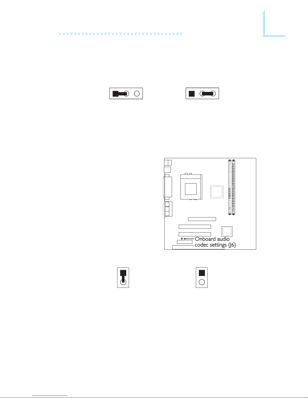
2.7 Jumper Settings for the Onboard Audio Codec
Onboard Audio Codec Settings - Jumper J6
AMR may come as primary
or secondary. The audio codec
on the system board is
primar y.
If you are using a primary
AMR on the AMR slot, please
set J6 to Off. If you are using
a secondary AMR on the
AMR slot or no AMR card is
installed on the AMR slot, you
must set J6 to On.
Off: Onboard
Audio Codec Secondary
On: Onboard
Audio Codec Primary
(default)
1
2
1
2
123 12 3
2-3 On:
Clear CMOS Data
1-2 On: Normal
(default)
7. Press <Esc> to return to the main menu of the BIOS setup
utility. Select Save & Exit Setup and press <Enter>.
8. Type <Y> and press <Enter>.
2
24
Hardware Installation
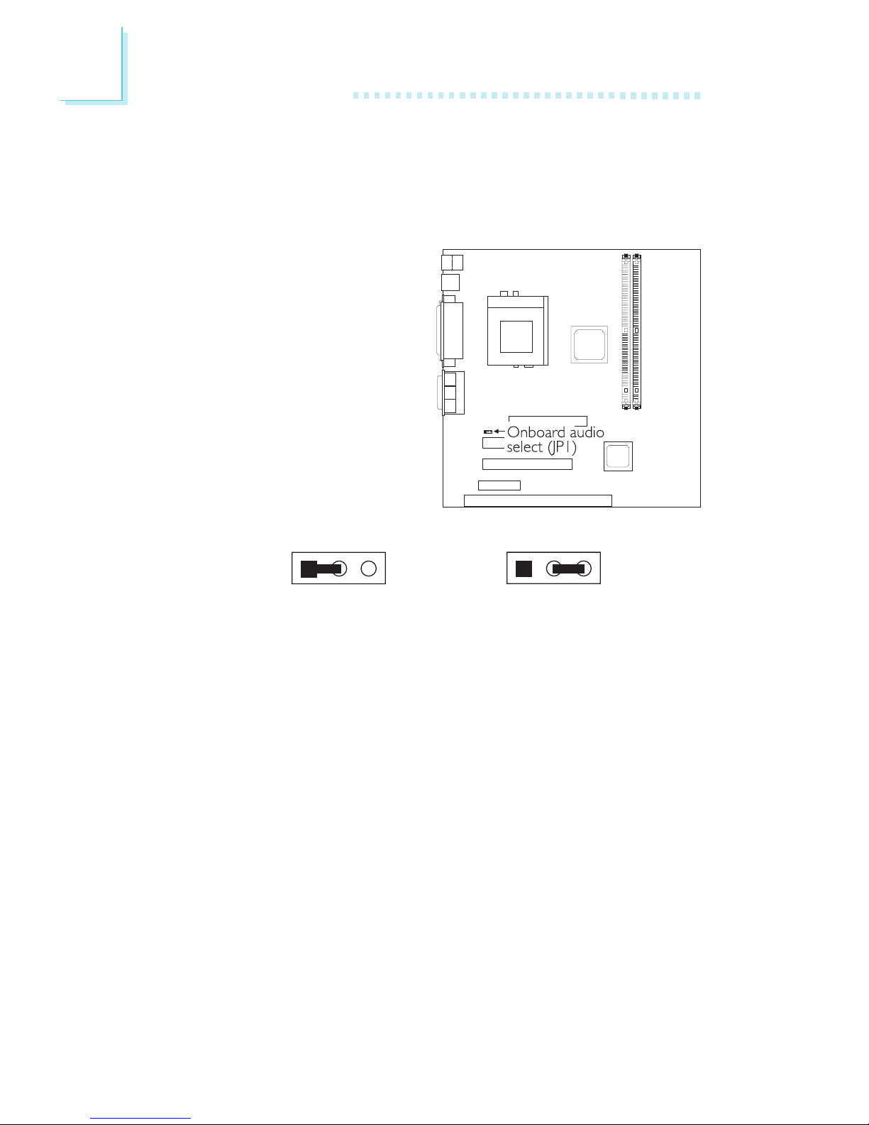
2.8 Jumper Settings for the Onboard PCI Audio Creative ES1373 (CA34-SU only)
Onboard PCI Audio Select - Jumper JP1
The CA34-SU system board
uses the Creative ES1373
PCI audio chip. This jumper is
used to enable or disable the
PCI audio chip. By default, the
PCI audio chip is enabled. If
you wish to install an audio
add-in card, please set this
jumper to 2-3 On - disabled.
123 123
2-3 On:
Onboard PCI Audio
Disable
1-2 On:
Onboard PCI Audio Enable
(default)
2
Hardware Installation
25
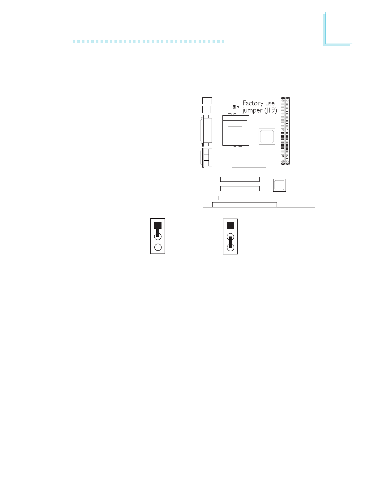
2.9 Factory Use Jumper
Factory Use Jumper - Jumper J19
This jumper is for factory use
only. Please leave it in its
default setting: 1-2 On.
1-2 On: Default
1
2
3
1
2
3
2-3 On
2
26
Hardware Installation
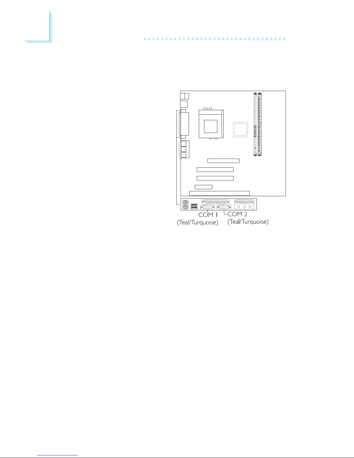
2.10 Ports and Connectors
2.10.1 Serial Ports
The system board is
equipped with onboard serial
ports (COM 1 and COM 2)
- both in Teal/Turquoise color
located at the ATX double
deck ports of the board.
These ports are RS-232C
asynchronous communication
ports with 16C550Acompatible UARTs that can
be used with modems, serial
printers, remote display
terminals, and other serial
devices. You can set the serial
ports I/O address in the
Integrated Peripherals submenu of the BIOS.
2
Hardware Installation
27
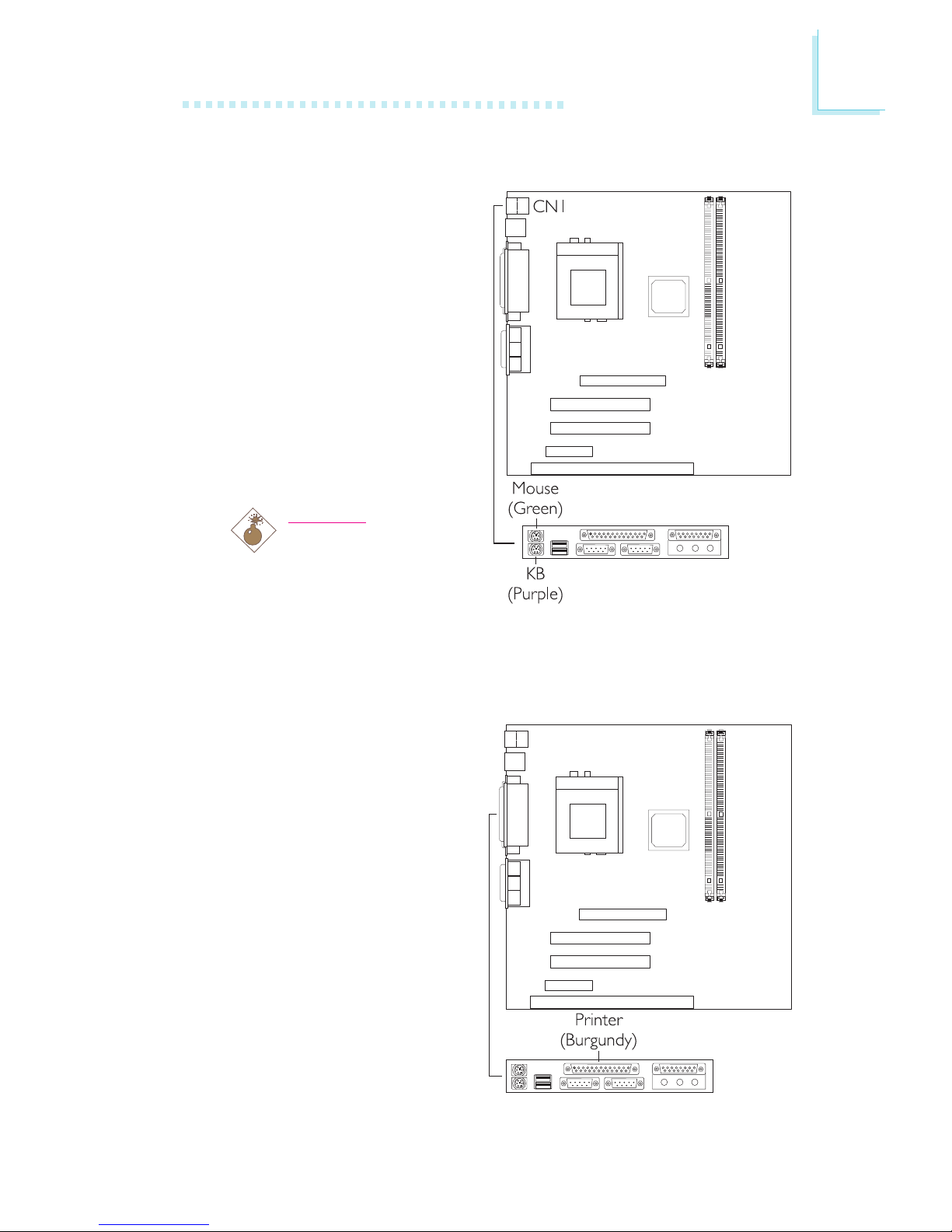
2.10.2 PS/2 Mouse and PS/2 Keyboard Ports
The system board is
equipped with an onboard
PS/2 mouse (Green) and
PS/2 keyboard (Purple)
ports, both at location CN1
of the system boards ATX
double deck ports. The PS/2
mouse port uses IRQ12. If a
mouse is not connected to
this port, the system will
reserve IRQ12 for other
expansion cards.
Warning:
Make sure to turn off
your computer prior
to connecting or
disconnecting a mouse
or keyboard. Failure to do so may damage the system board.
2.10.3 Parallel Port
The system board has a
standard printer port
(Burgundy) located at the
ATX double deck ports of
the board for interfacing
your PC to a parallel printer.
It supports Normal, ECP
and EPP modes. You can set
the ports mode in the
Integrated Peripherals
submenu of the BIOS.
 Loading...