

DFI CA33-SC User Manual

CA33-SC
Rev. A+
43200021
System Board Users Manual
Carte Mère Manuel Pour Utilisateur
System-Platine Benutzerhandbuch
Tablero Electrónico del Sistema Manual del
Usuario

Copyright
This publication contains information that is protected by copyright. No part of it may
be reproduced in any form or by any means or used to make any transformation/
adaptation without the prior written permission from the copyright holders. This
publication is provided for informational purposes only. The manufacturer makes no
representations or warranties with respect to the contents or use of this manual and
specifically disclaims any express or implied warranties of merchantability or fitness for
any particular purpose. The user will assume the entire risk of the use or the results of
the use of this document.
The manufacturer reserves the right to revise this publication and make
changes to its contents at any time, without obligation to notify any person or
entity of such revisions or changes.
Le fabricant se réserve le droit de revoir cette publication et deffecteur des
changements dans son contenu sans obligation dun préavis quelconque à qui
que ce soit.
Der Hersteller behält sich das Recht vor, den Inhalt dieses Handbuchs jederzeit
und ohne Benachrichtigung zu überarbeiten und abzuändern.
El fabricante reserva el derecho de corregir esta publicación y hacer cambios a
sus contenidos en cualquier tiempo, sin obligación de notificar a cualquier
persona o entidad de tales revisiones o cambios.
© 2000. All Rights Reserved.
Trademarks
Microsoft
®
MS-DOS®, WindowsTM, Windows® 95, Windows® 98, Windows® 2000 and
Windows NT® 4.0 are registered trademarks of Microsoft Corporation. Intel®, Pentium
®
III and Celeron
TM
are registered trademarks of Intel Corporation. VIA CyrixIII is a
registered trademark of VIA Technologies, Inc. Award is a registered trademark of Award
Software, Inc. Other trademarks and registered trademarks of products appearing in this
manual are the properties of their respective holders.
Caution:
Danger of explosion if battery incorrectly replaced.
Replace only with the same or equivalent type recommended by the manufacturer.
Dispose of used batteries according to the battery manufacturers instructions.
FCC and DOC Statement on Class B
This equipment has been tested and found to comply with the limits for a Class B
digital device, pursuant to Part 15 of the FCC rules. These limits are designed to
provide reasonable protection against harmful interference when the equipment is
operated in a residential installation. This equipment generates, uses and can radiate
radio frequency energy and, if not installed and used in accordance with the instruction
manual, may cause harmful interference to radio communications. However, there is no
guarantee that interference will not occur in a particular installation. If this equipment
does cause harmful interference to radio or television reception, which can be
determined by turning the equipment off and on, the user is encouraged to try to
correct the interference by one or more of the following measures:
Reorient or relocate the receiving antenna.
Increase the separation between the equipment and the receiver.
Connect the equipment into an outlet on a circuit different from that to which the
receiver is connected.
Consult the dealer or an experienced radio TV technician for help.
Notice:
1. The changes or modifications not expressly approved by the party responsible for
compliance could void the user's authority to operate the equipment.
2. Shielded interface cables must be used in order to comply with the emission
limits.
English
Français
Deutsch
Español

Table of Contents / Table des Matières / Inhaltsverzeichnis / Tabla de Contenidos
Chapter 1 - Introduction
1.1 Features and Specifications............................................................................................
1.2 Package Checklist................................................................................................................
Chapter 2 - Hardware Installation
2.1 System Board Layout ......................................................................................................
2.2 Frequency Ratio Settings for Processors...............................................................
2.3 Jumper Settings for Selecting the CPUs Front Side Bus...............................
2.4 Jumper Settings for Selecting the CPU Type........................................................
2.5 Jumper Settings for the Onboard Audio Codec...............................................
2.6 Jumper Settings for Clearing CMOS Data............................................................
2.7 Connectors..............................................................................................................................
Chapter 3 - Award BIOS Setup Utility
3.1 Entering the Award BIOS Setup Utility....................................................................
3.2 Setting the Date and Time..............................................................................................
3.3 Selecting the Hard Drive and Floppy Drive Type............................................
3.4 Selecting the Boot Sequence of the Drives..........................................................
3.5 Setting the Processor Serial Number Function...................................................
3.6 Selecting the External System Bus Clock of the Processor.........................
3.7 Selecting the Power Lost Resume State..................................................................
3.8 Enabling the AC97 Modem............................................................................................
3.9 Loading Fail-Safe Settings/Optimal Settings...........................................................
3.10 Setting the Supervisor/User Password...................................................................
Chapter 4 - Supported Softwares
4.1 VIA Hardware Monitor...................................................................................................
4.2 VIA Service Pack................................................................................................................
4.3 Audio Drivers and Software Application..............................................................
4.4 Drivers and Utilities Installation Notes....................................................................
6
19
38
39
40
41
42
43
46
48
49
49
20
21
23
24
25
26
28
51
52
55
56
Note:
The users manual in the provided CD contains detailed information about the
system board. If, in some cases, some information doesnt match those shown in this
manual, this manual should always be regarded as the most updated version. To
view the users manual, insert the CD into a CD-ROM drive. The autorun screen
(Main Board Utility CD) will appear. Click Users Manual.

Introduction
1
4
Read Me First
This page contains a summary of the important notes that must be given special
attention to prior to using the system board.
1. Processor
The frequency ratio of some processors may have been locked by the
manufacturer. If you are using this kind of processor, setting an extended
ratio for the processor will have no effect. The system will instead use its
factory default ratio.
The frequency ratio of processors greater than 8x has been locked by
the manufacturer and will no longer have the flexibility of using extended
ratios. Therefore, the system will use the processors factory default ratio.
Selecting an external bus clock other than 66MHz, 100MHz or 133MHz
may result to the processors or systems instability and are not
guaranteed to provide better system performance.
2. System Memory - The system board supports both VCM and PC SDRAM
DIMMs. If you are using more than one DIMM, make sure you insert the
same type of DIMMs into the DIMM sockets. Using different types (VCM or
PC SDRAM) of DIMMs may cause problems.
3. 5VSB Power - If you are using the (1) Wake-On-LAN and/or (2) Wake-On-
Ring (internal modem) functions, the 5VSB power source of your power
supply must support ≥720mA.
4. Drivers - Make sure to reboot the system after each driver installation.
Problems will occur if you reboot only after installing all the drivers.
Lisez Moi dAbord
Cette page contient un condensé des notes importantes quil faut prendre en
considération avant dutiliser la carte système.
1. Processeur
La taux de la fréquence de quelques processeurs au-dessus peut avoir
été blocké par le fabricant. Si vous utilisez ce genre de processeur, mettre
une taux étendue pour le processeur aura non effet. Le système utilisera
la taux défaut de lusine plutôt.
La taux de la fréquence de processeurs plus grand que 8x ont été
blocké par le fabricant et naura plus la flexibilité dutiliser de taux
étendus. Le système utilisera la taux défaut de lusine plutôt.
Le fait de sélectionner une horloge de bus externe autre que 66MHz,
100MHz ou 133MHz peut rendre le processeur ou le système instable et
ne garantit pas doffrir de meilleures performances système.
2. Mémoire Système - La carte système suppor te à la fois les VCM et DIMM
PC SDRAM. Si vous utilisez plus dune DIMM, prenez soin dinsérer le même
type de DIMM dans les logements DIMM. Le fait dutiliser des DIMM de
type différents (VCM ou PC SDRAM) peut engendrer des problèmes.
3. Alimentation 5VSB - Si vous utilisez les fonctions (1) Eveil Lan (Wake-On-
Lan) et/ou (2) Eveil Sonnerie (Wake-On-Ring) (modem interne), la source
dalimentation 5VSB de votre bloc dalimentation doit supporter ≥ 720mA.
4. Pilotes - Prenez soin de réamorcer le système après linstallation de chaque
pilote. Des problèmes apparaîtront si vous réamorcez seulement après
linstallation de tous les pilotes.

1
Introduction
5
Lesen Sie Diese Anleitung Zuerst Durch
Auf dieser Seite ist eine Zusammenfassung aller Hinweise enthalten, die vor der
Benutzung der Systemplatine unbedingt beachtet werden müssen.
1. Prozessor
Die Frequenzrate von einige, Prozessoren konnte vielleicht von Hersteller
gesperrt sein. Wenn Sie diese Ar t von Prozessor benutzen, wird das
eingeben eine erweiterte Rate für den Prozessor keine Wirkung haben.
Das System wird stattdessen den Standard Fabrikrate benutzen.
Die Frequenzrate von Prozessoren, welche größer als 8x sind, sind von
Hersteller gesperrt, und werden nicht länger die erweiterten Raten
Flexibilität haben. Das System wird stattdessen den Standard Fabrikrate
benutzen.
Ein Auswählen eines Bus-Taktgebers, welcher von den Frequenzen 66MHz,
100MHz oder 133MHz abweicht, kann eine Unstabilität des Prozessors
oder des Systems verursachen. Eine bessere Betriebsleistung des Systems
kann durch eine solche Einstellung nicht gewährleistet werden.
2. Systemspeicher - Die Systemplatine unterstützt die VCM- sowie die PC-
SDRAM-DIMMs. Falls mehr als ein DIMM verwendet wird, darf nur derselbe
Typ der DIMMs in die DIMM-Steckfassungen eingesetzt werden, da andere
DIMM-Typen (VCM oder PC SDRAM) zu Konflikten führen können.
3. 5VSB-Stromversorgung - Falls Sie die (1) Wake-On-LAN- und/oder (2)
Wake-On-Ring-Funktionen (internes Modem) anwenden, unterstützt die 5VSBStromquelle Ihres Netzgerätes eine Leistung von ≥720 mA.
4. Treiber - Das System muß nach jedem Installieren eines Treibers neugestartet
werden. Probleme werden nur dann auftreten, wenn das System nach dem
Installieren aller Treiber neugestar tet wird.
Leer Me Primero
Esta pagina contiene informationes importantes que se deben prestar mucha
attention antes del uso de la tabla de sistema
1. Procesador
La proporción de frecuencia de algunos procesadores de arriba uede
que ha sido bloqueada por el fabricante. Si usted está utilizando esta
clase de procesador, configurando la ración para el procesador no
tendrá efecto. El sistema en vez utilizará la proporción implícita de la
fábrica.
La ración de frecuencia de los procesadores mayor que 8x ha sido
bloquada por el fabricante y ya no tendrá la flexibilidad de utilizar las
proporciones extendidas. El sistema utiliza su proporción implícita de la
fábrica.
Seleccionando un reloj de bus externo otro que 66MHz, 100MHz o
133MHz puede resultar la inestabilidad del procesador o del sistema y
no son garantizados para proveer una mejor ejecución de sistema.
2. Memoria de Sistema - El tabla del sistema suporta ambos, el VCM y el PC
SDRAM DIMMs. Si usted está utilizando más que un DIMM, asegura de
insertar el mismo tipo de DIMM dentro del encaje de DIMM. Utilizando
diferentes tipos (VCM o PC SDRAM) de DIMM puede causar problemas.
3. 5VSB Potencia - Si estas usando las funciones de (1) Wake-On-LAN y/o
si se esta usando el (2) Wake-On-Ring(que es el modem interno). El 5VSB
potencia debe soportar una corrient (>) mas grande que ≥720mA.
4. Drivers - Asegurese de reboot o rebootear el sistema cada vez que se
instala un nuevo Driver. Problemas suelen ocurrir si se rebootea solo una
vez despuez de haber terminado con las instalacionens de todos los drivers.

Introduction
1
6
Expansion Slots
The system board is equipped with 1 dedicated AGP slot, 2 dedicated PCI slots
and 1 shared ISA/AMR slot. AMR (Audio/Modem Riser) is an interface designed
for installing an audio riser card, modem riser card or audio/modem riser card
that is compliant to the AMR specification.
1.1 Features and Specifications
Caractéristiques et Spécifications
Leistungsmerkmale und Technische Daten
Características y Especificaciones
1.1.1 Features
Chipset
VIA® 82C693A/82C686A AGPset
Processor
The system board is equipped with a switching voltage regulator that
automatically detects 1.30V to 2.05V.
Pentium
®
III FCPGA 133MHz FSB (533EB-866EB) or 100MHz FSB (500E-
800E) processor
Celeron
TM
66MHz FSB: FCPGA (566MHz-600MHz) or PPGA (300A-
533MHz) processor
Future VIA CyrixIII processor
System Memory
16MB to 512MB using VCM (Virtual Channel Memory) or PC SDRAM
DIMM (unbuffered or registered)
Two 168-pin DIMM sockets
Uses x64 or x72 PC SDRAM, 3.3V
: PC-66 SDRAM DIMM for 66MHz FSB processors
: PC-100 SDRAM DIMM for 100/66MHz FSB processors
: PC-133 SDRAM DIMM for 133MHz FSB processors
ECC supported (uses x72 PC SDRAM DIMM)
Chapter 1 - Introduction
Introduction
Einleitung
Introducción
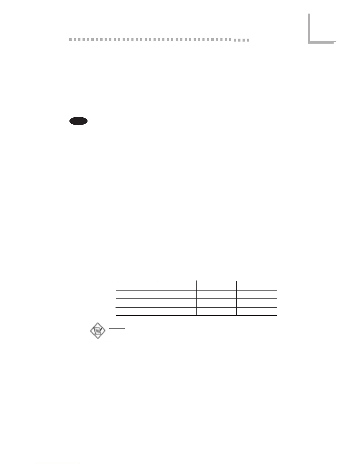
DIMMs
2MBx64/x72
4MBx64/x72
8MBx64/x72
Memory Size
16MB
32MB
64MB
English
DIMMs
16MBx64/x72
32MBx64/x72
Memory Size
128MB
256MB
Note:
If you are using more than one DIMM, make sure you insert the same type
of DIMMs into the DIMM sockets. Using different types (VCM or PC
SDRAM) of DIMMs may cause problems.

1
Introduction
7
Onboard Audio Features
Supports Microsoft® DirectSound/DirectSound 3D
AC97 supported with full duplex, independent sample rate converter for
audio recording and playback
ATX Double Deck Ports (PC 99 color-coded connectors)
2 USB ports
2 NS16C550A-compatible DB-9 serial ports
1 SPP/ECP/EPP DB-25 parallel port
1 mini-DIN-6 PS/2 mouse port
1 mini-DIN-6 PS/2 keyboard port
1 game/MIDI port
3 audio jacks: line-out, line-in and mic-in
Connectors
1 connector for 2 additional external USB ports
1 connector for IrDA interface
2 IDE connectors
1 floppy drive interface supports up to two 2.88MB floppy drives
1 20-pin ATX power supply connector
1 Wake-On-LAN connector
1 Wake-On-Ring connector
CPU, chassis and AGP fan connectors
2 CD audio-in connectors
1 TAD connector for telephony audio devices
PCI Bus Master IDE Controller
Two PCI IDE interfaces support up to four IDE devices
Supports ATA/33 or ATA/66 hard drives
PIO Mode 3 and Mode 4 Enhanced IDE (data transfer rate up to 16.6MB/
sec.)
Bus mastering reduces CPU utilization during disk transfer
Supports ATAPI CD-ROM, LS-120 and ZIP
IrDA Interface
The system board is equipped with an IrDA connector for wireless connectivity
between your computer and peripheral devices. It supports peripheral devices
that meet the HPSIR or ASKIR standard.
USB Ports
The system board supports 4 USB ports. Two onboard USB ports are located
at the ATX double deck ports of the board. The J21 connector on the system
board allows you to connect the optional 3rd and 4th USB ports. These
optional USB ports, which are mounted on a card-edge bracket, will be
provided as an option. USB allows data exchange between your computer and
a wide range of simultaneously accessible external Plug and Play peripherals.
BIOS
Award BIOS, Windows
®
95/98/2000 Plug and Play compatible
Supports SCSI sequential boot-up
Flash EPROM for easy BIOS upgrades
Supports DMI 2.0 function
2Mbit flash memory
Desktop Management Interface (DMI)
The system board comes with a DMI 2.0 built into the BIOS. The DMI utility in
the BIOS automatically records various information about your system
configuration and stores these information in the DMI pool, which is a part of

Introduction
1
8
the system board's Plug and Play BIOS. DMI, along with the appropriately
networked software, is designed to make inventory, maintenance and
troubleshooting of computer systems easier.
1.1.2 System Health Monitor Functions
The system board is capable of monitoring the following system health
conditions.
Monitors CPU/system temperature and overheat alarm
Monitors VCORE/3.3V/5V/12V/2.5V voltages and failure alarm
Monitors CPU/chassis fan speed and failure alarm
Automatic CPU/chassis fan on/off control
Read back capability that displays temperature, voltage and fan speed
If you want a warning message to pop-up or a warning alarm to sound when an
abnormal condition occurs, you must install the VIA Hardware Monitor utility.
This utility is included in the CD that came with the system board. Refer to the
VIA Hardware Monitor section in chapter 4 for more information.
1.1.3 Intelligence
Automatic CPU/Chassis Fan Off
The CPU and chassis fans will automatically turn off once the system enters the
Suspend mode.
Dual Function Power Button
Depending on the setting in the Soft-Off By PWR-BTTN field of the Power
Management Setup, this switch will allow the system to enter the Soft-Off or
Suspend mode.
Wake-On-Ring
This feature allows the system that is in the Suspend mode or Soft Power Off
mode to wake-up/power-on to respond to calls coming through an internal or
external modem.
Important:
If you are using a modem add-in card, the 5VSB power source of your
power supply must support a minimum of
≥
720mA.
RTC Timer to Power-on the System
The RTC installed on the system board allows your system to automatically
power-on on the set date and time.
Wake-On-LAN
The Wa ke-On-LAN function allows the network to remotely wake up a Soft
Power Down (Soft-Off) PC. Your LAN card must support the remote wakeup
function.
Important:
The 5VSB power source of your power supply must support ≥720mA
(minimum).
AC Power Failure Recovery
When power returns after an AC power failure, you may choose to either
power-on the system manually, let the system power-on automatically or return
to the state where you left off before power failure occurs. Refer to Selecting
the Power Lost Resume State in chapter 3 for more information.
1
Introduction
9
Français
ACPI
The system board is designed to meet the ACPI (Advanced Configuration and
Power Interface) specification. ACPI has energy saving features that enables PCs
to implement Power Management and Plug-and-Play with operating systems that
support OS Direct Power Management.
Virus Protection
Most viruses today destroy data stored in hard drives. The system board is
designed to protect the boot sector and partition table of your hard disk drive.
1.1.1 Caractéristiques
Chipset
VIA® 82C693A/82C686A AGPset
Processeur
La carte système est équipée dun régulateur de commutation de voltage qui
détecte automatiquement de 1.30V à 2.05V.
Pentium
®
III FCPGA 133MHz FSB (533EB-866EB) ou 100MHz FSB (500E-
800E) processeur
Celeron
TM
66MHz FSB: FCPGA (566MHz-600MHz) ou PPGA (300A-
533MHz) processeur
Futur VIA CyrixIII
processeur
Mémoire Système
Mémoire allant de 16Mo à 512Mo utilisant VCM (Virtual Channel Memory)
ou PC SDRAM DIMM (tampon ou enregistrées)
Deux sockets DIMM 168 broches.
Utilise x64 ou x72 PC SDRAM, 3.3V
- PC-66 SDRAM DIMM pour processeurs 66MHz FSB
- PC-100 SDRAM DIMM pour processeurs 100/66MHz FSB
- PC-133 SDRAM DIMM pour processeurs 133MHz FSB
ECC supporté (utilise x72 PC SDRAM DIMM)
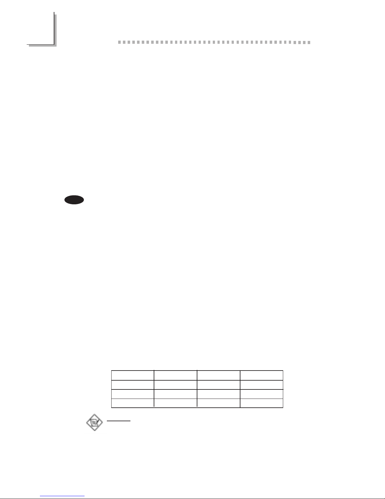
Note:
Si vous utilisez plus dune DIMM, prenez soin dinsérer le même type de
DIMM dans les logements DIMM. Le fait dutiliser des DIMM de type
différents (VCM ou PC SDRAM) peut engendrer des problèmes.
DIMMs
2MBx64/x72
4MBx64/x72
8MBx64/x72
Mémoire
16MB
32MB
64MB
DIMMs
16MBx64/x72
32MBx64/x72
Mémoire
128MB
256MB
Logements dExtension
La carte système est équipée de 1 logement AGP dédiés 2 logements PCI
dédiés et 1 logement ISA/AMR partagé. AMR (Riser Audio/Modem) est dune
interface destinée à linstallation dune carte audio riser, carte modem riser ou
dune carte audio/modem réhausseur conforme aux spécifications AMR.
Caractéristiques Audio sur Carte
Supporte DirectSound de Microsoft
®
/DirectSound 3D de Microsoft
®
AC97 supporté avec full duplex, convertisseur de vitesse déchantillonnage
indépendant pour enregistrement audio et lecture.

Introduction
1
10
Ports Double Module ATX (Connecteurs PC 99 avec codes couleur)
2 Ports USB
2 port série DB-9 compatible NS16C550A
1 port parallèle DB-25 SPP/ECP/EPP
1 port souris PS/2 mini-DIN-6
1 port clavier PS/2 mini-DIN-6
1 port jeu/MIDI
3 prises audio: ligne de sortie (line-out), ligne dentrée (line-in) et entrée
micro (mic-in)
Connecteurs
1 connecteur pour 2 ports USB supplémentaires
1 connecteur pour interface IrDA
2 connecteurs IDE
1 connecteur de lecteur de disquettes supportant jusquà deux lecteurs de
disquettes de 2.88Mo
1 connecteur dalimentation ATX 20 broches
1 connecteur Wake-On-LAN
1 connecteur Wake-On-Ring
Connecteurs de ventilateurs de CPU, de châssis et de AGP
2 connecteurs dentrée audio CD
1 connecteur TAD pour les matériels de téléphonie audio
Contrôleur IDE de BUS Maître PCI
Deux interfaces PCI IDE supportant jusquà quatre matériels IDE
Supporte des disques durs ATA/33 ou ATA/66
IDE Améliorés Mode 3 et 4 PIO (vitesse de transfert de données allant
jusquà 16.6Mo/sec.)
La gestion de Bus réduit lutilisation du CPU pendant les transferts sur
disque
Supporte les CD-ROM ATAPI, LS-120 et ZIP
Interface IrDA
La carte système est équipée dun connecteur IrDA pour les connexions sans fil
entre votre ordinateur et des périphériques. Il supporte les périphériques qui
sont conformes aux standards HPSIR ou ASKIR.
Ports USB
La carte système supporte 4 por ts USB. Deux ports USB sur carte se trouvent
sur les ports double deck ATX de la carte. Le connecteur J21 situé sur la carte
système vous permet de connecter les 3
ème
et 4
ème
ports USB optionnels. Ces
ports USB optionnels, qui sont montés sur un support latéral de carte, vous
seront fournis en option. USB permet léchange de données entre votre
ordinateur et un grande éventail de périphériques externes Plug and Play
accessibles simultanément.
BIOS
Compatible avec Award BIOS, Windows
®
95/98/2000 Plug and Play
Supporte lamorçage séquentiel SCSI
EPROM Flash pour une mise à niveau facile du BIOS
Supporte la fonction DMI 2.0
Mémoire Flash 2Mbit
Interface de Gestion de Bureau (DMI)
La carte système est livrée avec un DMI 2.0 intégré au BIOS. Lutilitaire DMI
dans le BIOS enregistre automatiquement diverses informations concernant la
configuration de votre système et stocke ces informations dans la liste DMI, qui

1
Introduction
11
est une partie du BIOS Plug and Play de la carte système. DMI, accompagné
du logiciel en réseau approprié, est conçu pour rendre linventaire, lentretien et
le dépannage du système de lordinateur plus facile.
1.1.2 System Health Monitor Fonctions
La carte système est capable de gérer les conditions de santé système
suivantes.
Alarme de température et de surchauffe de CPU/système de Moniteurs
Alarme déchec et de voltage VCORE/3.3V/5V/12V/2.5V de moniteurs
Alarme déchec et de vitesse de ventilateur de CPU/châssis de moniteurs
Contrôle de marche/arrêt automatique de ventilateur de CPU/châssis
Capacité de relecture affichant la température, le voltage et la vitesse de
ventilateur
Si vous désirez quun message davertissement apparaisse ou quune alarme
retentisse lorsque quune condition anormale se produit, vous devez installer VIA
Hardware Monitor. Cet utilitaire est compris dans le CD qui est livré avec la
carte système. Reportez vous à la section concernant Utilitaire VIA Hardware
Monitor dans le chapitre 4 pour de plus amples informations.
1.1.3 Intelligence
Arrêt automatique de Ventilateur de CPU/Châssis
Les ventilateurs de CPU et de châssis sarrêteront automatiquement une fois que
le système est entré en mode Suspension.
Bouton dAlimentation à Fonction Double
En fonction du paramétrage dans le champ Soft-Off By PWR-BTTN du
Programme dInstallation de la Power Management Setup, ce commutateur
permettra à votre système dentrer en mode Soft-Off ou Suspension.
Wake-On-Ring
Cette caractéristique permet au système qui se trouve en mode Suspension ou
en mode Arrêt Alimentation par Logiciel de se réveiller/sallumer pour répondre
à des appels provenant dun modem interne ou externe.
Important:
Si vous utilisez une carte complémentaire de modem, la source
dalimentation de 5VSB de votre boîtier dalimentation doit supporter un
minimum de
≥
720mA.
Minuterie RTC pour Allumer le Système
Le RTC installé sur la carte système permet à votre système de sallumer
automatiquement à une date et heure présélectionnée.
Wake-On-LAN
La fonction Wake-On-LAN permet au réseau de réveiller à distance un PC Mis
Hors Tension par Logiciel (Soft Power Down ou Soft- Off). Votre carte LAN
doit supporter la fonction de réveil à distance.
Important:
La source dalimentation 5VSB de votre boîtier dalimentation doit supporter
≥
720mA (minimum).
Introduction
1
12
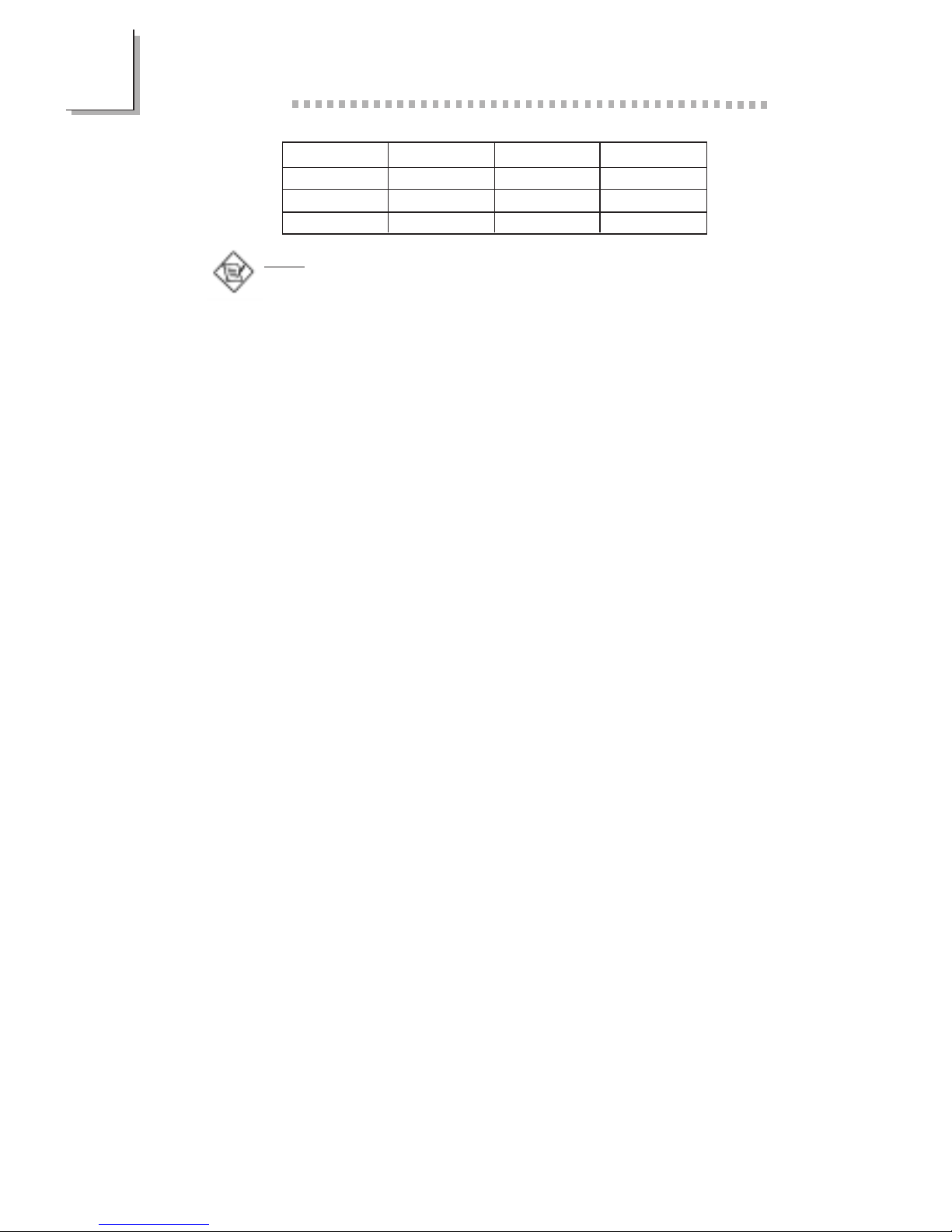
DIMMs
2MBx64/x72
4MBx64/x72
8MBx64/x72
Speicher
16MB
32MB
64MB
DIMMs
16MBx64/x72
32MBx64/x72
Speicher
128MB
256MB
Deutsch
Récupération après Défaillance dAlimentation CA
Quand lalimentation revient après une défaillance dalimentation CA, vous pouvez
choisir dallumer le système manuellement, de laisser le système sallumer
automatiquement ou de retourner à létat que vous aviez quitté avant que la
défaillance dalimentation se produise. Reportez vous à Choisir létat de
Redémarrage Après Coupure de Courant dans le chapitre 3 pour plus
dinformations.
ACPI
La carte système est conçue de façon à être conforme aux spécifications ACPI
(Configuration Avancée et Interface dAlimentation). ACPI comporte une fonction
déconomie dénergie qui permet aux PC de mettre en uvre la Gestion
dAlimentation et Plug and Play avec des systèmes dexploitation qui supportent
la Gestion dAlimentation Directe de Système dExploitation.
Protection contre les Virus
La plupart des virus détruisent les données stockées sur les disques durs. La
carte système est conçue pour protéger le secteur damorçage et la table de
partition de votre disque dur.
1.1.1 Leistungsmerkmale
Chipset
VIA
®
82C693A/82C686A AGPset
Prozessor
Die Systemplatine ist mit einem Spannungsregler ausgestattet, durch welchen
automatisch Spannungen von 1,30V bis 2,05V festgestellt werden.
Pentium
®
III FCPGA 133MHz FSB (533EB-866EB) oder 100MHz FSB (500E-
800E) prozessor
Celeron
TM
66MHz FSB: FCPGA (566MHz-600MHz) oder PPGA (300A-
533MHz) prozessor
Zukünftige VIA CyrixIII prozessor
Systemspeicher
Speicher von 16MB bis 512MB mit ohne VCM (Virtual Channel Memor y)
oder PC SDRAM DIMM (Pufferspeicher oder registriert)
Zwei DIMM-Fassungen mit 168poligem Anschlußstecker.
Funktioniert mit ´64- oder ´72-PC-SDRAM, 3,3V
- PC-66 SDRAM DIMM für 66MHz-FSB-Prozessore
- PC-100 SDRAM DIMM für 100/66MHz-FSB-Prozessore
- PC-133 SDRAM DIMM für 133MHz-FSB-Prozessore
ECC-unterstützt (funktioniert mit ´72-PC-SDRAM-DIMM)
Hinweis:
Falls mehr als ein DIMM verwendet wird, darf nur derselbe Typ der DIMMs
in die DIMM-Steckfassungen eingesetzt werden, da andere DIMM-Typen
(VCM oder PC SDRAM) zu Konflikten führen können.

1
Introduction
13
Erweiterungssteckfasssungen
Die Systemplatine ist mit 1 dedizierten AGP-Steckfassungen, 2 dedizierten PCI-
Steckfassungen und 1 gemeinsam benutzter ISA/AMR-Steckfassung versehen
ausgestattet. AMR (Audio-/Modem-Riser) ist eine Schnittstelle für die Installation
einer Audio-Riserkarte, einer Modem-Riserkarte oder einer Audio-/Modem-
Riserkarte, die der AMR-Vorschrift entspricht.
Audiomerkmale auf Platine
Unterstützung des Microsoft
®
DirectSound/DirectSound 3D
AC97 mit Unterstützung des Vollduplexbetriebs, unabhängigem
Abtastratenumwandler für die Aufnahme und Wiedergabe
ATX-Zweietagen-Anschlüsse (PC 99 mit farbkodierten Steckverbindungen)
2 USB-Anschlüsse
2 serieller DB-9-Anschluß, kompatibel mit NS16C550A
1 DB-25-Parallelanschluß SPP/ECP/EPP
1 Mini-DIN-6-Anschluß für eine PS/2-Maus
1 Mini-DIN-6-Anschluß für eine PS/2-Tastatur
1 Spiel-/MIDI-Anschluß
3 Audio-Anschlußbuchsen: Ausgangsleitung, Eingangsleitung und Mikrofon-
Eingang
Anschlußstecker
1 Anschlußfassung für 2 zusätzliche externe USB-Anschlüsse
1 Anschluß für die IrDA-Schnittstelle
2 IDE-Anschlüsse
Unterstützung von bis zu zwei 2,88MB-Floppylaufwerken durch einen
Floppylaufwerksanschluß
1 20poliger Anschlußstecker für das ATX-Netzgerät
1 Anschlußstecker für Wecken durch LAN
1 Anschlußstecker für Wecken durch Ring
CPU-, Chassis- und AGP-Ventilators Anschlüsse
2 CD-Eingangsanschlüsse
1 TAD Anschlußteil für Fernsprechaudiogeräte
PCI-Bus-Master-IDE-Controller
Unterstützung von bis zu vier IDE-Geräten durch zwei PCI-IDE-Schnittstellen.
Unterstützung der Festplatten ATA/33 oder ATA/66
Erweitertes IDE des PIO-Modus 3 und 4 (Datenübertragungsgeschwindigkeit
von bis zu 16.6MB/Sek.).
Verminderte CPU-Benutzung während Diskettenübertragung dank dem Bus-
Master.
Unterstützung des ATAPI CD-ROMs, LS-120 und ZIP.
IrDA-Schnittstelle
Die Systemplatine ist mit einem IrDA-Anschluß versehen, durch welche eine
kabellose Verbindung zwischen Ihrem Computer und Peripheriegeräten hergestellt
werden kann. Diese Schnittstelle unterstützt Peripheriegeräte, die der HPSIR und
ASKIR-Norm entsprechen.
USB-Anschlüsse
Die Systemplatine Unterstützung der 4 USB-Anschlüsse. Zwei USB-Por ts auf der
Hauptplatine befinden sich auf den ATX-Doppeldeck-Ports der Platine. Der J21Anschluß auf der Systemplatine ermöglicht es dem Benutzer, die optionalen 3.
und 4. USB-Por ts anzuschließen. Diese auf der Halterung an der Kartenkante
montierten optionalen USB-Ports können als Option verwendet werden. Durch
USB können Daten zwischen Ihrem Computer und einer großen Auswahl an

Introduction
1
14
gleichzeitig zugänglichen externen Plug and Play Peripheriegeräten ausgetauscht
werden.
BIOS
Kompatibilität mit Award BIOS, Windows
®
95/98/2000 Plug and Play
Unterstützung des sequentiellen SCSI-Ladens
Flash EPROM für ein einfaches Aktualisieren des BIOS
Unterstützung der DMI-2.0-Funktion
Flash-Speicher (2Mbit)
Desktop-Management-Schnittstelle (DMI)
Die Systemplatine ist mit einem DMI 2.0 ausgestattet, die im BIOS integriert ist.
Durch das DMI-Dienstprogramm im BIOS werden automatisch verschiedene
Informationen über die Konfiguration Ihres Systems registriert, wonach diese
Informationen im DMI-Speicher gespeichert werden. Dieser DMI-Speicher bildet
einen Teil des Plug and Play BIOS und des DMI der Systemplatine, zusammen
mit der richtig mit dem Netzwerk verbundenen Software. Auf diese Weise soll
der Unterhalt und die Fehlersuche des PC-Systems erleichtert werden.
1.1.2 System Health Monitor Funktions
Durch die Systemplatine können die folgenden gesundheitlichen Bedingungen
Ihres Systems überwacht werden.
Überwachung der Temperatur des CPU/Systems und Warnsignal bei
Überhitzung
Überwachung der VCORE/3,3V/5V/12V/2,5V-Spannungen und Warnsignal bei
Ausfall
Überwachung der Geschwindigkeit des CPU-/Chassisventilators sowie
Warnsignal bei Ausfall
Automatisches Ein-/Ausschalten der des CPU-/Chassisventilators
Anzeige der Temperatur, Spannung und der Geschwindigkeit des Ventilators
Soll bei Auftreten einer abnormalen Situation eine Warnmeldung erscheinen oder
ein akustisches Warnsignal abgegeben werden, muß das VIA Hardware Monitor
installiert werden. Dieses Dienstprogramm ist auf der CD enthalten, welche mit
der Systemplatine geliefert wurde. Weitere Einzelheiten finden Sie unter dem
Abschnitt des VIA Hardware Monitor-Dienstprogramm in Kapitel 4.
1.1.3 Intelligente Ausstattungsteile
Automatisches Ausschalten des CPU-/Chassis-Ventilators
Die CPU- und Chassisventilatoren werden automatisch ausgeschaltet, wenn das
System in den Suspendier-Modus geschaltet wird.
Netzschalter mit doppelter Funktion
Je nach der Einstellung im Feld Soft-Off By PWR-BTTN im Power Management
Setup kann das System durch diesen Schalter ausgeschaltet oder in den
Suspendier-Modus geschaltet werden.
Aufwachen bei Klingeln (Wake-On-Ring)
Mit diesem Merkmal kann das System, welches in den Suspend- oder Soft-PowerOff-Modus geschaltet ist, aufgeweckt/eingeschaltet werden, um eingehende Anrufe
zu beantworten, die über ein internes oder externes Modem geleitet werden.
Wichtig:
Falls Sie eine interne Modemkarte verwenden muß die 5VSB-Stromquelle des
Netzgerätes in Ihrem PC mindestens
≥
720mA unterstützen.

1
Introduction
15
RTC-Taktgeber zum Einschalten des Systems
Durch den auf der Systemplatine installierten RTC kann Ihr System automatisch
am eingestellten Datum und zur eingestellten Uhrzeit eingeschaltet werden.
Wecken bei LAN (Wake-On-LAN)
Durch die Funktion Wecken bei LAN-Bereitschaft kann ein ausgeschalteter PC
ferngesteuert durch das Netzwerk eingeschaltet werden. Ihre LAN-Karte muß
dazu jedoch die Weckfunktion durch Fernsteuerung unterstützen.
Wichtig:
Die 5VSB-Stromversorgung Ihres Netzgerätes muß (mindestens) ≥720mA
unterstützen.
Wiederherstellung der Wechselstromversorgung nach einem Ausfall
Bei der Wiederherstellung der Stromversorgung nach einem Ausfall kann das
System entweder manuell oder automatisch eingeschaltet werden, oder Sie
können den Betrieb des Systems an der Stelle fortsetzen, wo der Betrieb durch
den Stromausfall unterbrochen wurde. Weitere Einzelheiten hierzu finden Sie unter
Auswaehlen des PWR Lost Resume Status in Kapitel 3.
ACPI
Diese Systemplatine entspricht der ACPI-Vorschrift (Erweiterte Konfiguration und
Leitsungsschnittstelle). ACPI besitzt Energiesparfunktionen, die es dem PC
ermöglichen, das Power-Management und Plug and Play mit Betriebssystemen
anzuwenden, durch welche das direkte OS-Power-Management unterstützt wird.
Virusschutz
Durch die meisten Viren werden heutzutage Daten auf Festplatten zerstört. Diese
Systemplatine wurde so entworfen, um dem Boot-Sektor und der
Partitionstabelle Ihres Festplattenlaufwerkes einen entsprechenden Schutz zu
bieten.
1.1.1 Características
Chipset
VIA® 82C693A/82C686A AGPset
Procesador
El tablero de sistema es equipado con el regulador de voltaje de cambio que
detecta automáticamente 1.30V a 2.05V.
Pentium
®
III FCPGA 133MHz FSB (533EB-866EB) o 100MHz FSB (500E-
800E) processador
Celeron
TM
66MHz FSB: FCPGA (566MHz-600MHz) o PPGA (300A-
533MHz) processador
Futuros VIA CyrixIII processador
Memoria de Sistema
Memoria de 16MB a 512MB utilizando VCM (Virtual Channel Memory) o
PC SDRAM DIMM (intermedia o registrado)
Dos enchufes de 168-terminales DIMM
Utiliza x64 o x72 PC SDRAM, 3.3V
- PC-66 SDRAM DIMM para procesadores de 66MHz FSB
- PC-100 SDRAM DIMM para procesadores de 100/66MHz FSB
- PC-133 SDRAM DIMM para procesadores de 133MHz FSB
ECC soportado (utiliza x72 PC SDRAM DIMM)
Español
Introduction
1
16
Nota:
Si usted está utilizando más que un DIMM, asegura de insertar el mismo
tipo de DIMM dentro del encaje de DIMM. Utilizando diferentes tipos (VCM
o PC SDRAM) de DIMM puede causar problemas.
DIMMs
2MBx64/x72
4MBx64/x72
8MBx64/x72
Memoria
16MB
32MB
64MB
DIMMs
16MBx64/x72
32MBx64/x72
Memoria
128MB
256MB
Ranuras de Expansión
El tablero de sistema es equipado con 1 ranuras de AGP dedicados, 2 ranuras
de PCI dedicados y 1 ranura de ISA/AMR. AMR (Audio/Contrahuella de
Módem) es un interfaz diseñado para instalar la tarjeta de audio contrahuella,
tarjeta de contrahuella módem o tarjeta de contrahuella audio/módem que es
complaciente a la especificación de AMR.
Características de Audio En tablero
Soporta DirectSound de Microsoft
®
/ DirectSound 3D de Microsoft
®
AC97 soportado con convertidor de tasa de muestra independiente, doble
completo para la grabación y playback del audio
Puertos de Cubierta Doble de ATX (Conectores de PC 99 color-cifrado)
2 puertos de USB
2 puerto de serie DB-9 NS16C550A-compatible
1 puerto paralelo de SPP/ECP/EPP DB-25
1 puerto de ratón PS/2 mini-DIN-6
1 puerto de teclado mini-DIN-6 PS/2
1 puerto de juego/MIDI
3 enchufes de audio: línea de salida, línea de entrada y mic de entrada
Conectores
1 conector para 2 puertos de USB externo adicional
1 conector para interfaz de IrDA
2 conectores de IDE
1 conector de disquete soporta hasta dos disquetes de 2.88MB
1 conector de fuente de alimentación de ATX de 20-terminales
1 conector de Wake-On-LAN
1 conector de Wake-On-Ring
Conectores de CPU, chasis y AGP abanicos
2 conectores de entrada de audio de CD
1 conector de TAD para los dispositivos de audio telefónico
Controlador de IDE Maestro de Bus PCI
Dos interfaces de PCI IDE soporta hasta 4 dispositivos de IDE
Soporta las unidades duras de ATA/33 o ATA/66
PIO Modo 3 y 4 Realzada IDE (tasa de transferencia de dato hasta
16.6MB/seg.)
Controlación de Bus reduce la utilización de CPU durante la trasferencia de
disco
Soporta ATAPI CD-ROM, LS-120 y ZIP
Interfaz de IrDA
El tablero de sistema es equipado con el conector de IrDA para la conexión de
radiotelegráfico entre su computadora y dispositivos de periferia. Sopor ta
dispositivos de periferia que se encuentra con el estándar de HPSIR o ASKIR.

1
Introduction
17
Puertos de USB
El tablero de sistema soporta 4 puertos de USB. Dos puer tos de USB en
tablero son situados en el doble puerto de la cubierta de ATX del tablero. El
conector J21 del tablero de sistema le permite conectar a los puertos dobles
de 3
rd
y 4th USB. Estos puertos opcionales de USB , los cuales son montados en
el soporte de extremo de la tarjeta, será provisto como una opción. USB
permite el intercambio de dato entre su computadora y un intervalo amplio de
periferias de Enchufar y Usar externa accesible.
BIOS
Award BIOS, Windows
®
95/98/2000 Enchufar y Usar compatible
Soporta el incio de secuencia de SCSI
Parpadea EPROM para fácil actualización de BIOS
Soporta la función de DMI 2.0
Memoria Instante (2Mbitios)
Interfaz de Administración de Desktop (DMI)
El sistema de tablero viene con DMI 2.0 establecido en el BIOS. La utilidad del
DMI en el BIOS graba automáticamente varias informaciones sobre la
configuración de su sistema y almace estas informaciones en la balsa de DMI,
que es parte del tablero de sistema Enchufar y Usar BIOS. DMI junto con
software de red apropiado, es diseñado para hacer más fácil el inventario,
mantenimiento y procedimiento para solucionar problema de los sistemas de
computadora.
1.1.2 Funciones de Monitor de Salud del Sistema
El tablero de sistema es capaz de vigilar las siguientes condiciones de salud de
sistema.
Monitores de temperatura de CPU/sistema y alarma de acaloramiento.
Voltajes de monitores de VCORE/3.3V/5V/12V/2.5V y alarma de fracaso
CPU de monitores / velocidad del abanico de chasis y alarma de fracaso
Control de encendido/apagado del abanico de CPU/chasis automático
Lea la capacidad de vuelta que presenta la temperatura, voltaje y velocidad
del abanico.
Si usted desea el mensaje de advertencia de extraerse o una alarma de
advertencia de sonar cuando ocurre una condición anormal, usted debe instalar
la VIA Hardware Monitor. Esta utilidad es incluido en el CD que viene con su
tablero de sistema. Consultarse en la sección de la Utilidad de VIA Hardware
Monitor en el capítulo 4 de este manual para más información.
1.1.3 Inteligencia
Abanico Apagado de CPU/Chasis automático.
Los abanicos de CPU y chasis apagarán automáticamente una vez que el sistema
entra al modo de Suspender.
Botón de Energía de Doble Función
Dependiendo en la configuración en el campo de Soft-Off By PWR-BTTN de
la Configuración de Power Management Setup, este interruptor permite el
sistema de entrar al modo de Soft-Off o Suspender.

Introduction
1
18
Campaneo de Despertar (Wake-On-Ring)
Esta característica permite el sistema que es en el modo de Suspender o en el
modo de Soft Power Off a despierto/encendido para responder a llamadas que
vienen desde un modem interno o externo.
Importante:
Si usted está utilizando la tarjeta incorporada de modém, el fuente de
energía de 5VSB de su fuente de alimentación debe soportar un mínimo de
≥
720mA.
Temporizador de RTC para Encender el Sistema
El RTC instalado en el tablero de sistema permite su sistema de encender
automáticamente en la fecha y el tiempo configurado.
Listo el Wake-On-LAN
La función de Wake-On-LAN permite el red de despertar remotamente el PC
de Apagar de Soft (Soft-Off). Su tarjeta de LAN debe sopor tar la función de
despertar remoto.
Importante:
El origen de energía de 5VSB de su fuente de alimentación debe soportar
>720mA (mínimo).
Recuperación de Fracaso de Energía AC
Cuando la energía vuelve después del fracaso de energía AC , usted puede elegir
a encender su sistema manualmente, dejar el sistema de encender
automáticamente o volver al estado donde usted dejó antes de ocurrir el
fracaso de energía. Consultar Seleccionando el Estado de Reanudar de la
Pérdida de Energía en el capítulo 3 para más información.
ACPI
El tablero de sistema es diseñado para encontrar con la especificación de ACPI
(Configuración Avanzada e Interfaz de Energía). ACPI tiene las características de
archivación de energía que activa PC para ejecutar la Administración de Energía
y Enchufar y Usar con los sistemas operativos que soporta la Administración de
Energía Directa de OS.
Protección de Virus
La mayoría de los viruses de hoy destroye el dato almacenado en los discos
duros. El tablero de sistema es diseñado para proteger el sector de inicio y
tabla de partición de su unidad de disco duro.
 Loading...