


COMMERCIAL WASHER
MODEL T-600 VENDED
C-SERIES CONTROL
OPERATOR’S MANUAL
INSTALLATION & OPERATION
INSTRUCTIONS
Please read this information and retain for reference.
WARNING - THIS WASHER IS EQUIPPED WITH DEVICES AND FEATURES RELATING TO ITS SAFE OPERATION. TO AVOID INJURY OR ELECTRICAL SHOCK, DO NOT PERFORM ANY SERVICING UNLESS QUALIFIED TO DO SO.
IT IS THE RESPONSIBILITY OF THE OWNER TO CHECK THIS EQUIPMENT ON A FREQUENT BASIS TO ASSURE ITS SAFE OPERATION.
A machine should not be allowed to operate if any of the following occur:
-Excessively high water level.
-If machine is not connected to a properly grounded circuit.
-If the door does not remain securely locked during the entire cycle.
-Vibration or shaking from an inadequate mounting or foundation.
WARNING - FOR SAFETY
1.Always shut off power and water supply before servicing.
2.Do not overload the washer.
3.Do not open door when cylinder is in motion or it contains water.
4.Do not bypass any safety devices of this washer.
5.Do not use volatile or flammable substances in or near this washer.
6.Keep all panels in place. They protect against shock and injury and add rigidity to the washer.
PREVENTIVE MAINTENANCE REQUIREMENTS
DAILY
-Check that the loading door remains securely locked and cannot be opened during the entire cycle.
-Check the water connections for leaks.
-Clean the top and sides of the cabinet to remove residue.
-Clean the soap dispenser and lid and check that all dispenser mounting screws are in-place and tight.
-Check the drain valve for leaking and that it opens properly.
-Check the loading door for leaks. Clean the door seal of all foreign matter.
-Leave the loading door open to aerate the washer when not in use.
QUARTERLY
-Make sure the washer is inoperative by switching off the main power supply.
-Check the V-belts for wear and proper tension.
-Clean lint and other foreign matter from around motor.
-Check all water connections for leaks.
-Wipe and clean the inside of the washer and check that all electrical components are free of moisture and dust.
-Remove and clean water inlet hose filters. Replace if necessary.
-Check anchor bolts - retighten if necessary
IMPORTANT: Replace any and all panels that were removed to perform daily and/or quarterly maintenance.
8514-227-001 REV A page 1

TABLE OF CONTENTS
|
Page |
|
No. |
Washer Specifications |
2 |
Mounting Dimensions |
3 |
Installation Instructions |
4 |
Operating Instructions |
8 |
Programming the Washer Control |
10 |
Displayed Washer Faults |
24 |
Servicing and Troubleshooting |
30 |
Accessories and Contact Information |
34 |
|
WASHER SPECIFICATIONS |
MODEL |
T-600 40 LB. WASHER |
CAPACITY |
40LBS/6 CUBIC FT. (18.2 kg/170 L) |
CYLINDER SIZE |
25” DIA X 21 1/8” DEEP (63.5cm X 53.7cm) |
ELECTRICAL |
208-240 VAC, 60 HZ, 1 OR 3 PHASE |
DRIVE SYSTEM |
SOFT START REVERSING INVERTER DRIVE, 2 HP MOTOR |
WASH SPEED |
50 RPM |
INTERMEDIATE |
412 RPM (60 G’S) |
EXTRACT |
|
FINAL EXTRACT |
532 RPM (100 G’S) |
MACHINE CONTROL |
PROGRAMMABLE COMPUTER |
WATER INLET |
2 SOLENOID OPERATED VALVES |
|
FLOW RATE: 9 GAL/MIN EACH, 30-120 PSI |
DRAIN VALVE |
3” DIAMETER (7.6 cm) |
8514-227-001 REV A page 2

INSTALLATION INSTRUCTIONS
All washers must be installed in accordance with all local, state and national building, electrical, plumbing and other codes in effect in the area.
WARNING - THESE INSTALLATION AND SERVICING INSTRUCTIONS ARE FOR USE BY QUALIFIED PERSONNEL ONLY. TO AVOID INJURY AND ELECTRICAL SHOCK DO NOT PERFORM ANY SERVICING OTHER THAN THAT CONTAINED IN THE OPERATING INSTRUCTIONS, UNLESS QUALIFIED.
FOUNDATION REQUIREMENTS
This machine is designed for use on or over bare concrete floor - not to be used above combustible flooring. The washer must be securely bolted and grouted to a substantial concrete floor, or mounted and grouted upon a suitable base that is securely bolted and grouted to a substantial concrete floor. CARE MUST BE STRESSED WITH ALL FOUNDATION WORK TO INSURE A STABLE UNIT INSTALLATION, ELIMINATING POSSIBILITIES OF EXCESSIVE VIBRATION. All installations must be made on sound concrete floors, 6 inches (150mm) or thicker. Anchor bolts or expansion anchors must be of a quality grade and a minimum of 5/8-inch (16 mm) diameter.
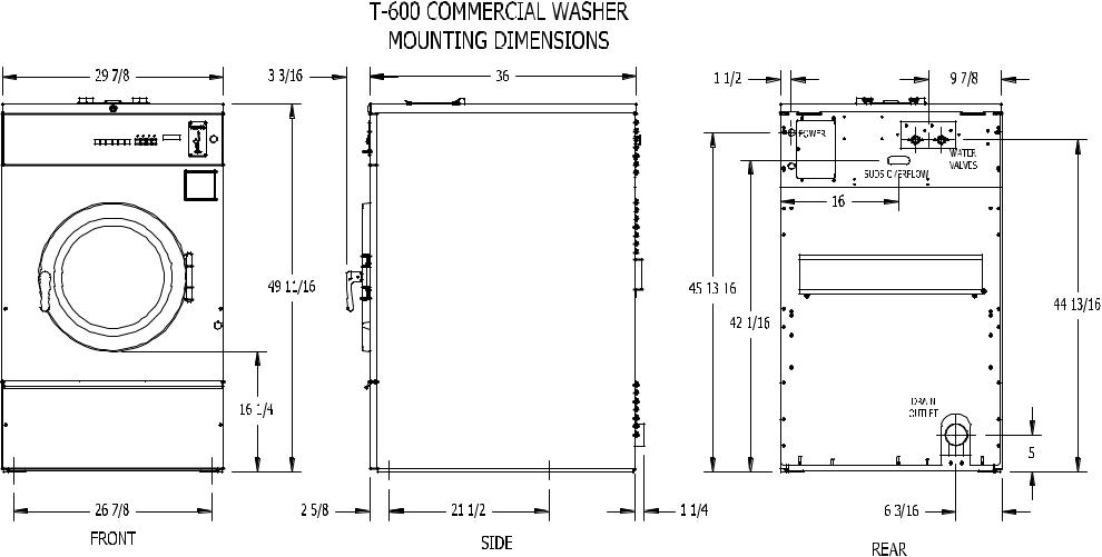
MOUNTING
A concrete pedestal or steel-mounting base that elevates the machine approximately 6 inches (150 mm) above the floor level is recommended to provide easy access to the loading door. Allow a minimum of 24 inches (600mm) of clearance behind the rear of the machine, to provide access for motor removal. Refer to Fig. 1-1 and 1-2 for machine bolt-down dimensions.
If an elevated concrete pedestal is desired, it should be embedded into the existing floor. Anchor bolts should be 5/8" x 8" (16 mm x 200 mm), grade 5 or better, headed by a 4 inch (10 cm) square fish plate and should protrude 1 7/8” (48 mm) above the finished surface of the pedestal. EXPANSION ANCHORS ARE NOT RECOMMENDED FOR USE IN CONCRETE PEDESTALS, BECAUSE THE ANCHORS ARE TOO CLOSE TO AN EDGE, CAUSING IT TO BREAK OUT. (See Fig. 1-1 and 1-3.)
8514-227-001 REV A page 4

8514-227-001 REV A page 5 |

PLUMBING
Water supply hoses are furnished with each machine. The threaded connections on the hoses¾ are -11½NHT.
Separate hot and cold water lines must be provided, maintaining 30 psi to 120 psi (207 kPa to 827 kPa) water flow pressure. A 140F (60C) degree hot water supply is recommended for best washing results. Do not exceed 180F (82C) degree water temperature.
DRAIN
The drain outlet tube at the rear of the machine is 3 inches (76 mm) in diameter. Any drain hose used must be lower than the drain valve to assure proper draining.
ELECTRICAL
WARNING
SHUT OFF POWER AND WATER BEFORE OPENING ANY SERVICE PANELS.
The Dexter T-600 single/three-phase 208-240VAC 60 Hz washing machines are intended to be permanently installed appliances. No power cord is provided. The machine should be connected to an individual branch circuit not shared by lighting or other equipment. The connection should be sheathed in liquid tight flexible conduit, or equivalent, with conductors of the proper size and insulation. A qualified technician should make such connections in accordance with the wiring diagram. (Suggest a minimum wire size of 12 ga.)
TO MAKE ELECTRICAL CONNECTIONS: Disconnect all power to the washer. Remove the top panel of the washer and locate the power terminal block near the back of the control compartment.
!If power is 208-240-3PH-60Hz, connect L1, L2, L3 and ground. If there is a high leg it must be connected to L3.
!If power is 208-240-1PH-60Hz, connect L1, L2 and Ground.
NOTE: It is important that the grounding screw next to the power terminal block TB- 1 be connected to a good external ground.
8514-227-001 REV A page 6
FUSING REQUIREMENTS:
SINGLEand THREE -PHASE 208-240VAC MODELS - 15 AMP TIME-DELAY (DUAL ELEMENT) FUSE (or equivalent circuit breaker)
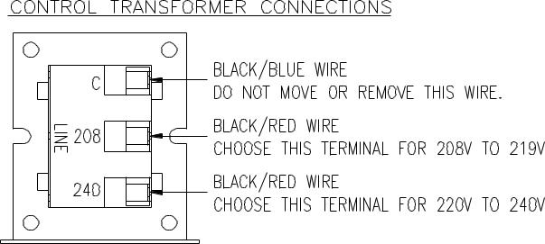
CONTROLS TRANSFORMER
The controls transformer is located inside the control trough and steps a range of 208 to 240 volts down to 115 volts. There are two terminals on the controls transformer for the primary (incoming) power. Use the terminal marked “208V” for power supplies between 208 and 219 volts. Use the terminal marked “240V” for power supplies between 220 and 240 volts.
CHECKOUT |
After all mounting, plumbing and electrical work is completed; the washer should be run through a cycle and checked for water leaks and proper functioning.
The cylinder should turn in a counterclockwise direction (viewed from the front of the machine) during intermediate spin and final spin. If spin is clockwise, the T1 and T2 motor wires going to T1 and T2 on the variable frequency drive should be swapped. Remove power to the machine before swapping wires.
8514-227-001 REV A page 7
OPERATING INSTRUCTIONS - STARTING THE WASHER
A.Load the clothes into the cylinder and latch the door securely. Be sure clothing does not get caught between the door gasket and tub front when closing the door. Maximum load is 40 pounds clothes, dry weight. Do not load the washer with more than 40 lbs.
B.Select the appropriate cycle temperatures for the load being washed.
C.Add low sudsing powdered detergent into the “detergent” compartment of the automatic dispenser on the top of the washer. If desired add fabric softener to the “fabric softener” compartment. Use the amount of fabric softener as recommended by the manufacturer.
If liquid wash products are used in the “detergent” compartment, they must be added at the beginning of the wash cycle.
If the machine is set for pre-wash, washing products can be added to the round opening of the dispenser or put in with the clothes when loading the washing machine.
D. Insert coins, tokens or debit card to meet the displayed vend price. The display will count down the amount needed to meet the vend price. Once the vend price is met, the display will read “PRESS START” and the start button LED will blink. If the door is not closed and latched, the display will read “CLOSE DOOR” and the control will wait until the door is latched to continue. Pressing the start button will begin the cycle and activate the ON light. The display will show the remaining cycle time in minutes. The clothes door will lock and remain locked until the end of the cycle.
END OF CYCLE
When the cycle is complete a 3-second tone will sound and the display will read “CYCLE DONE THANK YOU” until the door is opened. The door can now be opened. Leave the clothes door open when the machine is not in use.
8514-227-001 REV A page 8
EMERGENCY STOP / SAFETY DOOR LOCK
This machine is equipped with a Safety Door Lock that locks the door closed from when the cycle is started until the cycle is complete. The door lock prevents opening the door for up to 3 minutes if the power is interrupted during the cycle.
The Emergency Stop button pauses the washer and allows the door to be opened during the cycle after the Safety Door Lock releases. When the Emergency Stop button is pressed an alarm will sound and the display will begin counting down and read “STOP 3”, “STOP 2”, “STOP 1”. If the button is released before 3 seconds elapse, the alarm will stop and the cycle will continue normally. If the Emergency Stop is held down for 3 seconds, the display will count down and the washer will begin stopping movement and water flow and begin draining water from inside the washer. Though the machine may stop wash movement quickly, it may take up to 3 minutes for the door to unlock. During that time the alarm will continue to sound and the display will read “STOPPING”. When the alarm stops, the door may be opened. The washer may be restarted by closing and latching the door, and pressing the Start button. If the washer was stopped more than once before the final extract, the cycle will be cancelled. If the washer was stopped during final extract, the cycle will be ended. If the washer is stopped for more than 1 hour, the cycle will be terminated.
8514-227-001 REV A page 9
PROGRAMMING THE WASHER CONTROL
The washer control can be programmed to prompt the user for alternate vend prices, change washer cycle times, temperatures and many other options. This can be accomplished in two ways:
1.Manual programming utilizing the “Start”, “Hot”, “Warm” and “Cold” buttons
2.USB download of a customizable User File. For instructions on using the USB download feature, please contact your local Dexter distributor or visit dexterlive.com.
MANUAL PROGRAMMING:
The washer must be in idle mode for the manual programming menus to be accessed. Idle mode is when the washer is not actively running a wash cycle and the vend price is displayed on the screen.
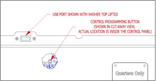
To enter the manual programming mode, the top of the washer must be unlocked and lifted slightly (it may be necessary to remove the screws for the soap box). The programming button is then pressed for 1 second. The control should display “PROGRAMMING”.
See the figure below for the location of the programming button in relation to the USB port (The USB port is exposed when the washer top is lifted).
8514-227-001 REV A page 10
When manual programming mode is entered, the “Start”, “Hot”, “Warm” and “Cold” buttons perform alternate functions.
 Button Name
Start
 Hot
Hot
Warm
 Cold
Cold
 Alternate Function in Programming Mode
Becomes the action to accept the displayed option or the “Enter” key
Becomes the action to move UP through displayed options (Press & hold for accelerated scrolling) Becomes the action to move DOWN through displayed options (Press & hold for accelerated scrolling) Becomes the action to move back a step (1 press) or EXIT from programming mode (press for 3 seconds)
These alternate functions allow the user to move through a menu of options to choose various programmable settings. The figure below shows the top level menu. Choosing an option from the top level menu will then display the next level of options (the sub menu).
8514-227-001 REV A page 11
 Loading...