

Section 6:
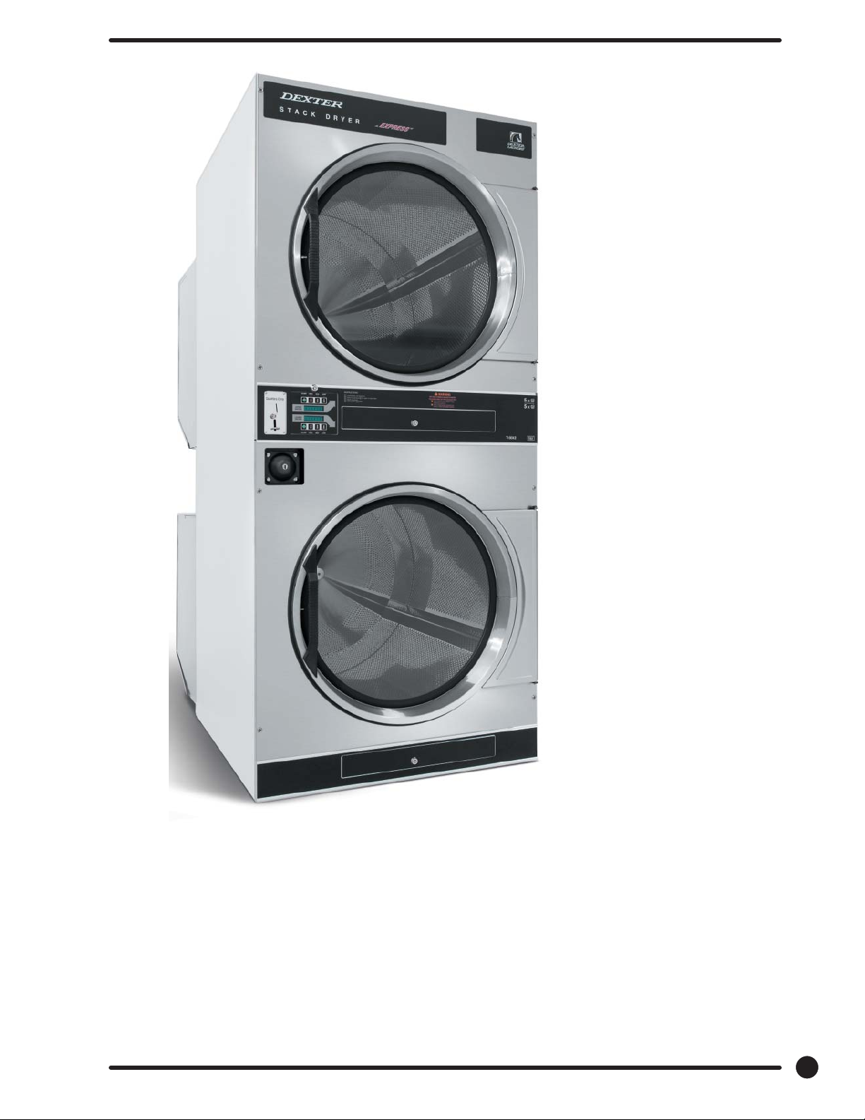
Parts Data
DC5 0X2
Part # 8533-085-001 9/14
73

13
1
11
10
2
3
6
4
12
5
14
11
5
10
7
6
4
2
3
1
12
74
Part # 8533-085-001 9/14

Cabinet Group
Key Part Number Description Quantity
* 9960-285-008 Door Assy., Loading Complete-Wht ..................................2
* 9960-285-011 Door Assy., Loading Complete-SS ..................................... 2
* 9960-285-007 Door Assy., Loading Complete-Chrome/BLK/SS ................. 2
1 9960-284-002 Door Assy., Loading-SS(ring only) ..................................... 2
1 9960-284-004 Door Assy., Loading-Chrome(ring only) ............................. 2
2 9982-353-002 Plate Assy., Hinge (Wht) No Pin ....................................... .2
2 9982-353-001 Plate Assy., Hinge (SS) No Pin ...........................................2
* 9545-012-015 Screw, Hinge to Door ...................................................... 8
* 8640-413-002 Nut, Hinge to Door .......................................................... 8
3 9212-002-004 Glass, Door ....................................................................2
4 9206-413-002 Gasket, Glass Black .......................................................... 2
* 9548-117-000 Support, Door Glass ....................................................... .2
5 9206-420-005 Gasket, Outer Rim Black ................................................... 2
6 9244-082-001 Handle, Loading Door ...................................................... 2
* 9545-018-017 Screw, Handle 1/4-20 x 3/8 .............................................. 4
* 9531-033-003 Stud, Door Catch ............................................................ 2
* 8640-413-001 Nut, Hex ........................................................................ 2
* 8640-413-003 Nut, Acorn ..................................................................... 2
* 9086-015-002 Catch, Loading Door ...................................................... .2
* 8638-190-009 Pop Rivet for mtg. catch .................................................. 4
* 8641-582-006 Lockwasher ..................................................................... 4
* 8640-399-001 Spring Nut ..................................................................... .6
7 9989-521-003 Panel Assy., Front- Lower (Wht) ....................................... 1
7 9989-521-001 Panel Assy., Front- Lower (SS) ........................................ .1
8 9989-517-003 Panel Assy., Front- Upper (Wht) ....................................... 1
8 9989-517-001 Panel Assy., Front- Upper (SS) ........................................ .1
* 9277-054-001 Insulation Front Panel, half moon (top) .............................. 2
* 9277-054-002 Insulation Front Panel, half moon (bottom) ........................ 2
9 9545-008-014 Screw, FLHDCR, 10B x 1 ..................................................14
* 8641-585-001 Lockwasher .................................................................... .6
* 8640-399-001 Nut, Spring ....................................................................12
10 9544-069-002 Strap, Hinge (Wht) ......................................................... .2
10 9544-069-005 Strap, Hinge (SS/Black) ...................................................2
* 9545-012-028 Screw, Hinge to Panel ..................................................... 8
11 9545-052-001 Screw, Door to Hinge Strap (Special Black Type) .............. .2
12 8641-436-003 Washer, Fiber ................................................................. 2
13 9021-041-001 Acceptor, Coin ................................................................ 1
* 9486-149-001 Retainer, Coin Acceptor ................................................... 2
14 9545-053-002 Screw ............................................................................ 4
* 9801-099-001 Switch, Optical ................................................................ .1
Part # 8533-085-001 9/14
75

Cabinet Group Continued
Key Part Number Description Quantity
15 9994-032-001 Escutcheon, Upper .......................................................... 1
16 9435-039-002 Trim, Overlay-Upper Blue .................................................. 1
16 9435-039-001 Trim, Overlay-Upper Black ................................................ 1
17 9994-033-001 Escutcheon, Lower .......................................................... 1
18 9435-023-001 Trim, Overlay-Lower Blue ..................................................1
18 9435-031-001 Trim, Overlay-Lower Black ................................................ 1
* 9545-020-009 Screw ............................................................................20
19 9412-167-002 Nameplate Stack Dryer Express Blue ................................ .1
19 9412-167-001 Nameplate Stack Dryer Express Black .............................. .1
20 9866-005-001 Lint Drawer Assembly Blue ............................................. . 2
20 9866-005-004 Lint Drawer Assembly Black ............................................. 2
21 9435-024-001 Overlay Trim, Lint Drwr-Blue ............................................. 1
21 9435-032-001 Overlay Trim, Lint Drwr-Black ............................................ 1
* 9532-074-003 Felt Seal ( back of lint screen assembly ) .......................... 2
* 9805-033-002 Lint Screen Assembly ONLY (no front) .............................. 2
* 9555-057-008 Replaceable Lint Screen Only ............................................2
22 8650-012-004 Lock and Key, Lint Drawer ............................................... 2
* 6292-006-010 Key 6101 only .................................................................. 2
* 9095-043-001 Cam, Lock ...................................................................... .2
* 9545-008-001 Lint Screen Strap Hold Down Screws 10Bx 1/4 .................32
23 9857-198-001 Controls Assy, Blue ......................................................... 1
23 9857-198-003 Controls Assy, Black ........................................................ 1
* 9627-869-001 Harness, Electronic Control ............................................. .1
24 8650-012-003 Lock and Key, Control .....................................................1
* 9095-041-001 Cam, Lock ...................................................................... 1
* 6292-006-007 Key only 6324 .................................................................. 1
* 9627-855-003 Harness, Heat Sensor ..................................................... .1
* 8640-276-002 Wire Nut Connector Grey .................................................. 4
25 9501-004-003 Sensor Temp Control ....................................................... 2
26 9501-008-001
* 9545-045-005 Screw, Round Head (Mounts sensor; phillips head) ............ 2
* 9209-037-002 Gromm.et, 3/16 ID ......................................................... 2
* 8544-006-001 Leg, Leveling 1/2” .......................................................... 4
* 9074-320-001 Cover, Cabinet (Top) ........................................................ 1
* 9277-041-017 Insulation Cabinet Cover ................................................ .1
* 9732-276-001
* 9732-102-013 LP Kit for 50Lb Stk Dryers.......................................................1
* 9732-243-001 Stack Dryer Trunion Puller.......................................................1
* 9544-041-002 Strap - Bead Tie .............................................................. 1
27 9942-038-005 Vault, Coin Box ............................................................... 1
* 9545-008-024 Screws, Mounting-Coin Vault ...........................................2
28 9897-099-002 Coin Box Assy, Large Blue ............................................... 1
28 9807-099-004 Coin Box Assy, Large Black .............................................. 1
Bracket for Heat Sensor Mounting (Under Basket) w/ sensor
Kit for Dryers without Neutral and using 208-240 volt
.. 2
........... 1
76
Part # 8533-085-001 9/14

19
20, 21
24
23
19
15
16
27
28
22
20, 21
26 25
22
17
18
Part # 8533-085-001 9/14
77
8
5
2
3
4
6
7
11
1
9
9
10
12
78
Part # 8533-085-001 9/14

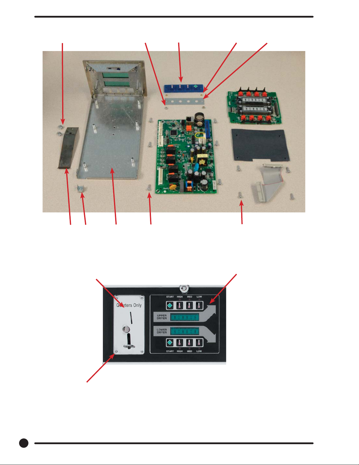
Control Parts Group
Key Part Number Description Quantity
* 9857-198-001 Controls Assy, Electronic Mounted With Membrane Switch, BLU ...1
* 9857-198-003 Controls Assy, Electronic Mounted With Membrane Switch, BLK ... 1
1 9826-008-001 Trough Assembly .................................................................. 1
2 9032-062-002 Button-Push, Control, Blue ................................................... 2
2 9032-062-001 Button-Push, Control, Black................................................... 2
3 9538-166-011 Spacer-Metal, 4mm ............................................................... 4
4 9486-158-001 Retainer-Push Button ............................................................ 2
5 8640-424-002 Nut-Hex, Elastic stop, #4-40 ................................................ 4
6 8652-130-038 Terminal-Grounding clip ........................................................ 1
7 9534-365-001 Spring-Flat, Control ............................................................... 1
8 9545-008-001 Screw-Hex, #10B x 1/4 ......................................................... 2
9 9545-044-010 Screw-Hex, #10B x 1/4 ........................................................ 10
9 8641-582-005 Washer-External tooth, #6 ................................................... 10
10 9435-038-001 Overlay-Control, Coin, Black ................................................. 1
10 9435-038-002 Overlay-Control, Coin, Blue .................................................. 1
11 9021-041-001 Acceptor-Coin, Optical ..................................................... 1
* 9486-149-001 Retainer, Coin Acceptor ................................................... 1
12 9545-053-002 Screw ............................................................................ 4
* 9801-099-001 Optical Sensor, Replacement.............................................1
Note: Jumpers required if using 1.5 Control on Older Machines (P9 Connection)
* 8220-155-001 Wire Assy, Jumper, 30Lb Stack Coin .................................. 1
* 8220-155-002 Wire Assy, Jumper, 50Lb Stack Coin .................................. 1
Part # 8533-085-001 9/14
79

Door Switch Group
Part Number Description Quantity
9539-487-001 Door Switches ................................................................ 2
Hinge Plate Cover
1 9074-340-002 Cover-Hinge, Black .....................................................................2
2 8636-008-010 Screw-TRHDCR, 10B x 3/8, Black........................................................4
2
1
80
Part # 8533-085-001 9/14

Bearing Housing Group
Key Part Number Description Quantity
J1 9241-189-002 Housing, Bearing .......................................................................2
J2 9036-159-003 Bearing, Ball Rear..................................................................... .2
* 9538-183-001 Spacer, Bearing ........................................................................ 2
* 9036-159-001 Bearing, Ball Front .................................................................... .2
J5 9545-017-017 Bolt, 1/2 x 3/4 ............................................................................8
J7 8640-417-002 Nut, 1/2 ....................................................................................8
* 9803-201-001 Bearing Housing Complete Ass’y (includes bearings,spacer) ..........2
J4 9545-017-018 Screw 1/2 x 1 1/2 ......................................................................4
Part # 8533-085-001 9/14
81

Burner Housing Group
Key Part Number Description Quantity
* 9803-207-001 Housing Assembly, Burner ...............................................2
1a 9452-730-001 Service Burner Plate Front… ............................................. 2
1 9452-729-001 Service Plate baffl e Recirculation Chamber Clean Out ......... 2
* 9545-008-006 Screws ........................................................................... 8
2 9545-008-001 Screw ...........................................................................16
18 9003-220-001 Angle, Burner Support ..................................................... 2
* 9545-008-006 Screw ........................................................................... .4
17 9048-020-002 Burner, Main ................................................................... 4
* 9545-008-006 Screw 10AB x 3/8” .......................................................... 4
* 9454-824-001 Panel, Back Burner Housing .............................................. 2
4 9545-008-001 Screw 10B x1/4” ............................................................ .8
5 9875-002-003 Electrode Assy, Ignition ................................................... 2
19 9545-045-001 Screw, Electrode Mtg 8B x 1/4” ......................................... 4
7 9379-186-001 Valve, Gas Shut Off ......................................................... 1
8 9857-134-001 Control Assy, Gas ............................................................ 2
9 9381-012-001 Manifold, Assy ................................................................ 2
* 9425-069-021 Orifi ce, Burner-Natural #27 .............................................. 4
* 9425-069-022 Orifi ce, Burner-LP #44 ...................................................... 4
10 9029-175-001 Bracket, Manifold ............................................................ .2
22 8615-104-038 Pipe Plug in end of Burner Manifold .................................. 2
* 9545-008-006 Screw ........................................................................... .4
12 9576-203-002 Thermostat, Hi-Limit .......................................................2
* 9538-142-001 Spacer, Hi-Limit .............................................................. 4
* 9545-045-007 Screw 8B x 3/4” ............................................................... 4
13 9074-329-001 Cover, Hi-Limit Stat Ignitor ............................................... 2
* 9545-008-006 Screw ............................................................................ 6
* 9576-207-008 Thermostat, Safety Shutoff ............................................ 2
* 9545-008-006 Screw ............................................................................ 4
15 9825-062-001 Cover, Safety Stat .......................................................... 2
* 9545-008-024 Screw ............................................................................6
16 9857-116-003 Control, Ignition Fenwall (3 trybox) ................................... 2
* 9732-102-013 Kit, LP Conversion 50Lb Stack Kit .................................... .2
* 9838-018-003 Welded One Piece Gas Pipe Assembly....................................1
82
Part # 8533-085-001 9/14

Burner Housing Group Photos
4
1
22
10
22
10
9
15
10
9
13
12
11
13
2
18
17
15
14
1A
5
5
16
8
Part # 8533-085-001 9/14
1A
83

Rear View
Key Part Number Description Quantity
* 9627-861-001 Wire Harness Overtemperature Switch/Air Switch ............... 2
* 9801-098-001 Switch Assy, Air Flow ....................................................... 2
1 9539-461-009 Switch, Air Flow ............................................................... 2
2 9029-200-001 Bracket, Switch- Air Flow ..................................................2
3 9008-007-001 Actuator, Switch ............................................................... 2
4 9451-169-002 Pin, Cotter ......................................................................2
5 9545-020-001 Screw 4-40 x 5/8” ........................................................... 4
* 8640-401-001 Nut, Special Twin .#4-40 ................................................. 2
* 9550-169-003 Shield, Switch ................................................................ .2
6 9376-322-001 Motor, Drive .................................................................. 2
7 9452-770-001 Plate, Motor Mounting ...................................................... 1
* 9545-029-008 Bolt 3/8” - 16 x 3/4”.................................................................8
* 8641-582-003 Lockwash Spring 3/8 ...............................................................8
8 9545-018-019 Screw, Motor Plate to Back Assy. 1/4-20x 2 1/2......................8
* 8641-582-007 Lockwasher 1/4........................................................................8
9 9538-163-006 Spacr.........................................................................................8
* 8641-581-017 Flat Washer 1/4 x 7/8.............................................................24
* 9209-086-002 Rubber Grommet......................................................................8
* 9538-166-006 Grommet Spacers.....................................................................8
* 9545-028-013 Screw, Set.................................................................................4
10 9962-018-002 Back Assy, Blower Hsg.............................................................2
11 9991-053-001 Support Assy, Intermed. Pulley ....................................... .2
12 9545-029-010 Bolt, Rd Hd 3/8-16 x 1 1/4 ............................................. . 6
12 8640-415-004 Nut Flange Wizlock 3/8” - 16 ............................................ 6
12 8641-581-035 Washer, Flat .................................................................. 6
13 9545-029-003 Bolt, 3/8-16 x 1 1/2 ........................................................ 2
14 9861-022-001 Arm Assy-Tension, Complete ........................................... 2
* 9487-200-003 Ring-Retaining ................................................................6
15 9908-048-003 Pulley Assy, Intermediate with bronze fl ange bearing ......... 2
* 9036-145-002 Bronze Flange Bearing .....................................................4
16 9908-047-002 Pulley Driven Tumbler ...................................................... 2
17 9040-076-009 Belt, Drive Motor............................................................. 2
18 9040-073-011 Belt, Driven Intermediate to Tumbler ............................... 2
19 9534-151-000 Spring, Tension ............................................................. . 2
20 9099-012-005 Chain, Tension ............................................................... 2
21 9248-022-002 Hook, Tension ............................................................... 2
* 9451-146-001 Pin, Damper Hinge ......................................................... .2
* 9074-334-001 Cover Duct Upper ............................................................ 1
22 9973-032-001 Heat Recirculation Assembly Duct ................................... .2
* 9453-169-013 Motor Pulley - Driver ....................................................... 1
* 9545-028-013 Set Screws ...................................................................... 2
* 9278-043-001 Impeller ..........................................................................2
23 8641-581-026 Washer, Flat 1/2” for Tumbler Pulley ..................................2
24 9545-017-009 Bolt, 1/2”-13 x 1 1/4 ........................................................ .2
25 8641-582-016 Washer, Star 1/2” for Tumbler Pulley ................................. 2
* 9545-008-001 Screw 10 Bx 1/4” ............................................................. 6
* 9545-014-004 Bolt, 5/16-18 x 5/8” ......................................................... .8
* 8640-400-003 Nut, 5/16-18 ....................................................................8
* 9538-184-001 Spacer, Shaft ................................................................. .2
* 9487-234-005 Ring Tolerance ................................................................. 2
* 9125-007-001 Damper Inside Duct Exhaust ............................................2
* 9125-007-002 Damper Inside Duct Exhaust ............................................1
* 8520-141-000 Nut, Spring .................................................................... .4
* 9074-335-001 Cover Duct Lower ........................................................... 1
* 9545-008-024 Screw 10ABx 3/8” ...........................................................72
* 9029-173-001 Bracket for Wire Harness Under Burner Housing ................2
84
Part # 8533-085-001 9/14

22
Rear View Photos
12
13
16
10
17
23, 24, 25
15
19
20
21
18
2
1
11
4
3
5
7
14
11
6
8
9
Part # 8533-085-001 9/14
85

Rear Panel & Cover Group
Key Part Number Description Quantity
1 9208-090-001 Rear Guard Side Panel 1 ................................................... 2
4 9545-008-024 Screws 10 AB x 3/8 .........................................................30
5 8502-649-001 Label - Connection Electrical ............................................. 1
8 9208-089-001 Rear Guard Back Panel ..................................................... 2
10 8502-600-001 Label Warning & Notice ....................................................1
11 8502-645-001 Label - Instructions .......................................................... 1
12 9109-113-001 Transition Assembly Outlet ...............................................1
13 9074-320-001 Top Cover Dryer Panel ..................................................... 1
14 9550-188-001 Top Burner Housing Heat Shield Inlet ................................ 1
15 9074-321-001 Top Panel Burner Housing Cover ....................................... 1
8
13
1
Screws
8
5
12
11
15
86
Part # 8533-085-001 9/14
14
8

Tumbler Group
Key Part Number Description Quantity
9848-131-001 Tumbler Assembly Galvanized w/spider ..............................2
G2 9568-013-001 Spider Assembly ............................................................. 2
G3 9497-226-002 Rod, Tumbler .................................................................. 6
G4 8640-417-005 Nut, 1/2 - 13 ...................................................................6
G6 8641-590-002 Washer, Special .............................................................. 6
G7 9552-013-000 Shim .............................................................................AR
* 9848-130-002 Tumbler Assembly Stainless Steel...................................... 2
G1 9848-130-001 Tumber Assembly Galvanized ............................................ 2
Part # 8533-085-001 9/14
87

Control Assembly Group
Key Part Number Description Quantity
* 9857-189-001 Control Assmbly Complete (all below included) ............................ .1
* 9108-117-001 Control Box Cover .................................................................... . 1
* 8220-001-478 Wire Assembly Green 7” ............................................................ 1
* 8639-621-007 Screw #10-32 x 12 Green ............................................................ 1
* 8641-582-006 Lockwasher Ext Tooth #10 .......................................................... 1
3 9897-026-002 Terminal Block Main Power Middle ............................................... 1
4 9897-026-001 Terminal Block ............................................................................ 2
* 9545-045-012 Screw #8 ABx 1/2 for terminal block ............................................ 6
5 8711-011-001 Transformer Ignition ................................................................... 2
* 9545-008-024 Screws 10AB x 3/8” ................................................................... 4
6 9982-348-001 Plate Assembly MTG Ignition Control........................................... .2
* 9545-008-024 Screws 10B x 1/4” MTG Above Plate and Others ........................... 4
7 9857-116-003 Ignition Control .......................................................................... 2
* 8640-411-003 #6-32 Nuts ............................................................................... .4
8 9631-403-009 Wire Assembly High Voltage Upper .............................................. 1
9 9627-860-001 Wire Harness Ignition Control Upper ............................................ 1
10 9627-860-002 Wire Harness Ignition Control Lower ............................................ 1
* 9053-067-002 Bushing Wire 7/8” ....................................................................... 4
13 9200-001-002 Fuseholder Assembly ................................................................. .3
14 8636-018-001 Fuse 1.5 Amp ............................................................................ .3
15 5192-299-001 Relay Power ...............................................................................2
16 9897-035-001 Terminal Block Assembly Main Power Inlet ................................... 1
* 9545-008-024 Screw #8 AB x 1/2” .................................................................... 2
* 8220-062-036 Wire Assembly Red/Black 14” ......................................................1
* 8220-062-037 Wire Assembly Red/White 14” ..................................................... 1
* 8220-062-038 Wire Assembly White 14” ............................................................ 2
21 9627-864-004 Wire Harness Motor Extension ..................................................... 2
* 9527-007-001 Stand Off - Wire Saddle / Arrowhead ..........................................13
* 9545-031-005 Screw 6 B x 3/8” ........................................................................ 4
22 9558-029-003 Strip Terminal Marker (Behind Input Power) .................................. 1
24 9627-863-001 Wire Harness Main Extension Access Under Burner Housing ......... 1
23 9631-403-008 Wire Ass’y - High Voltage Lower .................................................. 1
25 9627-859-001 Wire Harness - Main Power ......................................................... 1
88
Part # 8533-085-001 9/14

Control Assembly Group
13, 14
22
8
13, 14
24
25
22
16
23
16
9
8
7
5
15
4
3
4
15
5
7
Part # 8533-085-001 9/14
89

Coin Accecptor
Key Part Number Description Quantity
1 9021-041-001 Coin Accecptor, Optical ............................................................... 1
2 9801-099-001 Sensor-Optical, Replacement ....................................................... 1
3 9545-039-002 Screw, Heighth Bar, 3mm ............................................................ 2
* 9486-136-001 Retainer, Coin Acceptor ............................................................. 1
* 9545-053-002 Screw ......................................................................................4
90
Part # 8533-085-001 9/14

Notes
Part # 8533-085-001 9/14
91

Wiring Schematic for DC50x2
92
Part # 8533-085-001 9/14

Wiring Diagram for DC50x2
Part # 8533-085-001 9/14
93

Notes
94
Part # 8533-085-001 9/14

Section 7:
Voltage
Conversio n
Part # 8533-085-001 9/14
95

Instructions - Convert a Dual Voltage Stack Dryer from 120V to 208-240V
with Neutral Wire Only
1. Remove incoming power from the dryer. Use a known working voltmeter to check power.
2. Remove the cover of both the upper and lower control box assemblies from the dryer using a 5/16” wrench.
3. Move the black/blue wire from the N position of the main power terminal block to the L2 position of the main
power terminal block in the upper control box assembly. See Figure 6 below.
4. Move the white wire of the upper motor harness to an upper inner left terminal in the middle terminal block in the
lower control box assembly. See Figure 6 below.
5. Move the orange wire of the upper motor harness to an upper inner left terminal in the middle terminal block in
the lower control box assembly. See Figure 6 below.
6. Move the white wire of the lower motor harness to a lower inner left terminal in the middle terminal block in the
lower control box assembly. See Figure 6 below.
7. Move the orange wire of the lower motor harness to a lower inner left terminal in the middle terminal block in the
lower control box assembly. See Figure 6 below.
8. Reconnect power to the dryer and test to ensure proper operation; one line voltage to L1, one line voltage to L2,
the neutral to N, and the earth ground to E.
9. Reinstall the cover of both the upper and lower control box assemblies from the dryer using a 5/16” wrench.
96
Part # 8533-085-001 9/14

Part # 8533-085-001 9/14
97

Notes
98
Part # 8533-085-001 9/14

Section 9:
Maintenance
Part # 8533-085-001 9/14
99

Maintenance
Daily
1. Clean lint screen by unlocking and sliding out in their tracks for access. Use soft brush if
necessary. Failure to do so will slow drying and increase gas usage and temperatures through out
the dryer.
2. Check lint screen for tears. Replace if necessary.
Monthly
1. Remove lint accumulation from end bells of motor.
2. Clean lint from lint screen compartment.
3. Remove lint and dirt accumulation from top of the dryer and all areas above, and around the
burners and burner housing. Failure to keep this portion of the dryer clean can lead to a buildup
of lint creating a fi re hazard.
4. Inspect Recirculation burner housing for excessive buildup.
5. Place a few drops of light oil on top and bottom pivots of the clothes door hinge.
6. Grease bearings and shaft of intermediate drive pulley.
Quarterly
1. Check belts for looseness, wear or fraying.
2. Inspect gasket of door glass for excessive wear.
3. Check tightness of all fasteners holding parts to support channel.
4. Check tightness of tumbler shaft retaining nut. MUST MAINTAIN 150 FOOT LBS.
5. Remove lint accumulation from primary air ports in burners.
6. Grease pivot pins and tension arms where in contact with each other.
Semiannually
1. Remove and clean main burners.
2. Remove all orifi ces and examine for dirt and hole obstruction.
3. Remove all lint accumulation. Remove front panel, lint screen housing and remove lint
accumulation.
Annually
1. Check intermediate pulley bearings for wear.
2. Check and remove any lint accumulation from exhaust system.
NOTE: DRYER MUST NOT BE OPERATED WITHOUT LINT SCREEN IN PLACE
100
Part # 8533-085-001
© 2010 Dexter Laundry, Inc. | 2211 W. Grimes Ave, Fairfi eld, IA 52556, U.S.A. | 1-800-524-2954 | www.dexter.com
Dexter reserves the right to change part numbers and/or specifi cations
without notice.
 Loading...