


 Loading...
User’s Manual
Software Release 5

Chapter 1 |
Introduction |
Chapter 1
Introduction
1.1Welcome to DEXIS®
Welcome to the exciting world of DEXIS! And thank you for your recent investment in the DEXIS Digital X-ray System. We hope you will have an extraordinary experience with our products and services.
Our mission at DEXIS is to develop and support the Digital Radiography community around the world. We seek to build strong partnerships with our doctors and their teams based on long-term, interactive relationships.
Your new DEXIS Digital X-ray System was designed from the outset with you, the clinician, in mind. This is your tool. Learn to use it well and it will become an effective aid in your diagnosis, treatment and treatment planning process.
As with all new clinical tools, it is necessary to invest a certain amount of time for practice in order to become proficient with the DEXIS Digital X-ray System.
We strongly recommend that you register for in-office training with a certified DEXIS instructor and that you and all of your clinical team set aside 4 to 6 hours to learn the system together. This manual is not intended to serve as a substitute for this training. However, as preparation for the training we do encourage you to read the manual thoroughly and practice with it safely and carefully for at least one week prior to your training date.
Please note that this manual assumes that new users possess basic computer skills and an understanding of the Windows® operating system. Absent this experience, we strongly recommend that you obtain these skills through a computer course, video, or textbook. Your DEXIS representative may be able to suggest (although not endorse) one or more of these computer learning resources.
Unless otherwise stated, in this manual “CLICK” refers to a single left mouseclick . Most functions in the DEXIS software require a single left click. Erroneous or impatient double-clicking or right clicking may cause the program to func-
2

Chapter 1 |
Introduction |
tion improperly. Also, as a general request, please give the program time to start and complete each function before clicking again.
Let’s start your journey into the world of DEXIS Digital X-ray!
1.2What’s New in Release 5
This new release of the DEXIS software is a major update over previous releases. It is far and away the most comprehensive upgrade since the original software was introduced in 1995.
New 32-bit Software
The major improvement in this release is that the software has been completely rewritten line-by-line in 32-bit code.
The principal advantage of 32-bit software is that it should run much faster and more reliably. In addition, there will be a wider range of hardware available to interface with the software, including scanners and video cards.
Consistent with the new 32-bit architecture, the new release of DEXIS will now run in “native” format with the new Microsoft operating systems: Windows® XP® (home or professional) and Windows® 2000®.
This release also retains “backward compatibility” with earlier versions of Windows, including Windows® 98® and 95® Windows® NT®, and non-upgrade versions of Windows® ME®.
New Patient Administration Screen
The DEXIS Patient Administration program has been modified and improved as a result of requests from owners. The main window is now scaleable and a scroll bar has been added. Font size can also be controlled. A few other functional changes were introduced with DEXIS release 3.1 and are incorporated into this release, as well.
New Name: DEXray
The main DEXIS program has been renamed DEXray, consistent with its primary function: taking and displaying digital X-rays. Other changes include subtle
3

Chapter 1 |
Introduction |
modifications to the layout, including title bar appearance and icons. Following requests from owners, the “corners” and outline of any new on-screen “DEXrays” are now black instead of white (older images retain their original white background, created when the X-ray was first acquired).
New designations
New designations have been introduced to assist in identifying the origin of image sources. These designations include “DEXray by DEXIS” for an original X- ray image taken using a DEXIS sensor and DEXIS capture device. An X-ray taken using non-DEXIS hardware but acquired directly into the DEXray program will carry the designation “Original.” Additional designations that may appear include “Scanned,” “Imported,” “Derived,” and “Enhanced.”
These new designations are intended to provide greater security and reassurance with regard to the origin of images. They will be present whenever an onscreen image is enlarged or printed.
New Perio Mode ClearVu
The ClearVu image enhancement has been further refined to meet the needs of periodontists: crisp bone structures and ligatures are obtained with a mouse click. Furthermore, ClearVu mode now stays on when you switch patients. Also the printed ClearVu has been optimized giving sharper printed images in DEXray as well as in DEXwrite.
New Compare Feature
“Compare” is a new DEXray feature that allows the comparison of two images in order to ascertain their differences.
The four modes: “Side By Side” offers the images side by side and proportional in size; “Color Addition” shows density changes in color; “Subtraction” shows density changes in light/dark values; “Red-Green Stereo” from earlier editions is incorporated into “Compare.” The latter three modes allow for the alignment of the two selected images. Originally designed for the research community, “Compare” is now available to all DEXIS users.
4

Chapter 1 |
Introduction |
New DEXwrite Features
The chairside report generator DEXwrite has been extended in several respects: A generalized “Recepient” mechanism greatly simplifies sending reports to all kinds of recipients; reusable text blocks and input fields give greater flexibility in report generation.
New DEXsafe Feature
DEXsafe, a feature that allows you to easily backup your data, is now offered. DEXsafe is accessed from the DEXIS Administration screen. It allows you to choose full or incremental backup and to choose a specific drive.
New Help Features
The screen now shows the current DEXIS logo as an icon that leads to the Program Information screen. This screen offers two new functions:
•Help: allows access to the DEXIS software on-screen manual
•DEXIS Web Site: opens the DEXIS web site in the user’s browser.
5

Chapter 2 |
Installation, Care, and Maintenance |
Chapter 2
Installation, Care, and Maintenance
Most telephone calls for assistance received by the DEXIS Customer Care specialists stem from inadequate attention to hardware and software installation. Poor care of the DEXIS sensor or DEXIS capture device can result in damage to or destruction of the fragile electronic components. Also, inattention to basic maintenance procedures, including adjustment of the X-ray source, can lead to unacceptable image quality.
We strongly recommend using the installation services of a factory-trained DEXIS engineer or certified DEXIS installer. We also recommend that you engage a qualified computer specialist or an experienced network technician and develop a permanent relationship for your ongoing computer needs. We understand the prospective of “saving money” by implementing a seemingly more cost-effective solution; however, it is our experience that while this may be true in the short term, such decisions are considerably more expensive in the long run.
Naturally, turnover and attrition in a dental office will see team members come and go. The DEXIS Digital X-ray System is a highly sophisticated piece of equipment that must be handled with care and maintained in accordance with the manufacturer’s recommendations. Despite the pressures of a busy schedule, please take the time to ensure that all new team members become familiar with the equipment and the care that it requires.
After installing and testing your software, hardware and components, we suggest that you take the time to explore the software and read the on-screen manual.
When calling Technical Support for assistance, please make sure that you have access to the computer on which the DEXIS system is used and on which the manual may be displayed. You will be instructed where to find answers and solutions for your particular questions. This makes for optimal “over the phone” assistance.
6

Chapter 2 |
Installation, Care, and Maintenance |
2.1Overview of the DEXIS System
Upon opening your DEXIS kit you will notice three basic components: the DEXIS sensor with its PC Card (also referred to as “PCMCIA Card,” “Mobile Card” or “Board”), the DEXIS installation software and your full set of sensor holders.
2.2Hardware Requirements
Our current hardware system requirements are available in the support section on our website www.DEXray.com, from your representative and from our Customer Care Center. As technology changes, our requirements are updated to reflect such changes. Please consult current DEXIS systems requirements before the purchase of any hardware.
2.2.1 Hardware Platform
This version of DEXIS software is for use on common PC platforms of the singleuser type, including those with networks, both desktop and laptop varieties. The System Requirements for this software are the same as the minimum requirements stated for the operating system installed therein. Note that systems meeting only the minimum requirements may fail to deliver a satisfactory experience. Systems with faster processors, more memory, and bigger, faster hard drives will significantly enhance performance.
2.2.2 Operating System Platform
This software has been validated for use on the following members of the Microsoft Windows product family of operating systems:
•Windows 95 OSR2
•Windows 98 Second Edition
•Windows NT4 (see below for restrictions)
•Windows 2000
•Windows XP
Do not deploy this software for use on other versions of Microsoft Windows or on other operating systems that emulate the Windows operating system un-
7

Chapter 2 |
Installation, Care, and Maintenance |
less the software has been validated for use on that platform by our Technical Department.
Windows NT4 has only limited support for PC Cards; therefore, you need to install the software library “Cardware for Windows NT” in order to use the DEXIS sensor. “Cardware for Windows NT” is commercially available. Most video capture cards are also not supported under Windows NT.
2.2.3 Caution: Hardware & Software Upgrades
Every change in hardware or software exposes your business to risk. Computers containing patient records are “mission critical.” Careful consideration is required in order to minimize risk before changes are made to any system that is currently in use. Whether the change is to be made to hardware, to the operating system or to the DEXIS application software, you should be prepared to deal with an unexpected outcome including a catastrophic loss of data. For this reason, we offer the following suggestions for use with mission-critical systems:
Instead of upgrading hardware or operating system, consider purchasing a new pre-configured system. Computers are amazingly inexpensive today; bringing-up a new system in parallel with an existing system is a good way to avoid placing the existing system at risk. The existing system will remain productive while the new system is qualified and readied for full service. Consider the new computer as cheap insurance, but it’s even better than insurance because you get to keep it.
If you must upgrade your existing system, consider purchasing an additional hard drive and making a bootable, literal copy of the existing hard drive. Remove the original hard drive and make the changes to the newer (and probably larger) hard drive. With the original hard drive removed from the computer, it is not at risk and all of your data will be safeguarded. If the new changes are found to be unsatisfactory after a suitable evaluation period, you can always re-install the old hard drive and fully restore your previous environment.
Always back-up your data and store it offsite. Before assuming that your backup efforts have been successful, make sure that you understand the backup process and practice the restore process at least once on a test system. Verify that both the operating system and data have been preserved.
8

Chapter 2 |
Installation, Care, and Maintenance |
2.2.4 Diagnostic Imaging
It is in displaying images on the screen that your needs dramatically depart from the needs of ordinary computer users. The quality of image presentation will be important in your selection of a monitor and video card. Carefully evaluate your selection prior to purchase by using sample images that are known to be of diagnostic quality. Sample images, including a viewing program, are available from your DEXIS Representative. DEXIS users can make their own evaluation floppy by simply exporting with DEXview.
Here are a few things that we have learned after many years of experience:
•Premium monitors are highly recommended. Your needs are similar to those of a professional image scientist or a commercial photographer, so treat yourself to the best quality.
•Premium CRT-based monitors are still better than premium LCD-based monitors.
•A CRT monitor with an “Invar Mask” will be better than one with a mask of any other material.
•Monitors with tiny tri-color dots are better than monitors with colors in stripes or bars. You can examine the color arrangement with a loupe.
•Analog monitors seem to have better images than so-called digital monitors.
•When selecting a notebook computer, chose models with LCD screens recommended for use with photographic imaging.
2.2.5 Special Hardware Requirements
DEXray
The DEXray product requires a PCMCIA interface. These interfaces are also referred to as PC Card Readers. Most notebook computers include PC Card Readers while most desktop computers do not. It is not possible to add an external PC Card Reader to a notebook computer that does not have one built-in. Approved PC Card Readers for desktop computers are available from your DEXIS Representative. These accessories are easy to install and can be retrofitted to desktop computers with one available 3.5” floppy disk drive bay and one avail-
9

Chapter 2 |
Installation, Care, and Maintenance |
able PCI or ISA card position (specify PCI or ISA). Please refer to the Hardware and Software Installation section prior to installing this accessory.
DEXimage
DEXimage requires an image source and a capture device. The quality of the result cannot be better than the quality of the source. Expensive cameras may offer higher resolution still images at low frame rates, while full-motion video cameras may capture dozens of frames per second, none of them high resolution enough to allow enlargements.
Capture devices may be interfaced directly to boards installed in the back of the computer, or to interfaces like USB. The interface you choose may affect the performance or usability of the result. Ease of use is also important. A product that requires the user to transfer images from camera to computer in order to send images may be less usable than a product that transfers images in a “hands free” fashion.
Always test your camera installation as a “stand-alone” before interfacing to DEXimage.
A foot pedal can be used in DEXimage to start and stop the live video and to capture still pictures. DEXimage can handle foot pedals connected to a serial port and pedals connected to a game port. Some cameras have a capture button that can be used instead of a serial port foot pedal.
DEXscan
DEXscan requires a scanner. To scan ordinary paper images, such as your signature or office logo, a standard scanner may be used. If you intend to scan X- ray images a scanner with a transparency adapter is required. Be sure to select a scanner that is recommended by DEXIS and that has an interface that is appropriate for your installation.
2.3Hardware Installation
2.3.1 PC Card Reader Installation
Install the PC Card reader (PCMCIA slot) into your desktop computer following the manufacturer’s instructions, typically the card reader’s software and then
10
Chapter 2 |
Installation, Care, and Maintenance |
the card reader itself. When you turn your computer on, Windows should recognize the reader and load the appropriate drivers.
If you do not receive the message “New hardware found” call Technical Support for assistance.
DO NOT PLUG THE DEXIS PC CARD IN AT THIS TIME!
2.3.2 DEXIS Provided Foot Pedal
Plug the foot pedal cable into the serial port on the back of your desktop or laptop computer (9 pin male connector). See “Foot pedal or Wand Capture” on page 86 for instructions on how to use.
Please note: DEXIS provided foot pedals are for use with DEXimage software only. They will not work with any other camera software.
2.3.3 Additional Hardware
Please refer to the specific owner’s manuals for information on your computers, printers, scanners, card readers, foot pedals, monitors, and cameras for installation and use. Should you need technical assistance with any of these items, please consult the manufacturer of each specific item.
Again, we strongly recommend employing the services of a factory-trained DEXIS engineer or certified DEXIS installer. We also recommend that you engage a qualified computer specialist or (preferably) a network technician and create a sustainable relationship for your ongoing computer needs.
2.4Software Installation
Please follow these instructions to install your new DEXIS Digital X-ray System software. Your DEXIS system must be completely installed and tested before training can begin.
After installation, use the verification and testing instructions in “Installation Verification and Testing” on page 114. Following all the instructions will ensure that your system is fully functional. The system will be taught in the “Simulation” mode for all hardware not functioning at the time of training.
11
Chapter 2 |
Installation, Care, and Maintenance |
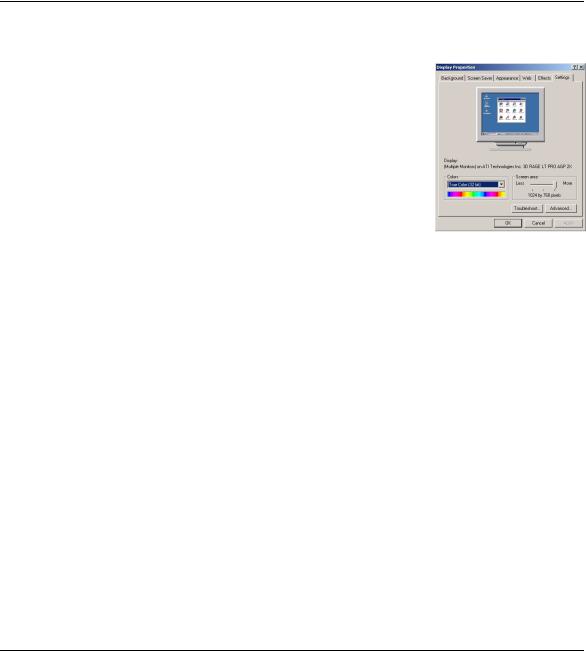
2.4.1 Display Settings
Before installing your DEXIS software, please change your display settings to best view the DEXIS screens.
1.Go to: “Start”, then “Settings” and click on “Control Panel”; double-click on the “Display” icon to open the Display Properties screen; click on the “Settings” tab at the top.
2.Under Colors: Choose “True Color” (16-bit) for laptop computers and flatpanel monitors. Choose 16-bit or 24-bit for all others.
3.Under “Screen area”: Recommended resolution is 1024 x 768, but the software will also work on all other resolutions. Always choose the native resolution for LCD monitors.
4.Click on “Apply” to apply these settings.
2.4.2 DEXIS Installation CD
The DEXIS installation software is delivered to you on a CD plus an additional floppy disk entitled “Sensor Disk.” This additional piece of software is used to maximize the resolution of your sensor.
Please note: If you purchased your computer through DEXIS, it will be delivered to you pre-loaded with software and initial information. Please refer to “Installation Verification and Testing” on page 114 to skip the installation steps and go directly to Verification.
2.4.3 Installation Planning
If you plan to run DEXIS on a stand-alone computer, there is not much to plan and you may proceed to the next section.
If you have a local area network, you need to designate a hard disk of one of the computers to hold the DEXIS data (images and patient data). This server disk needs to be shared so that it can be accessed (with read and write access) from all of the computers that will be running DEXIS software and will thus need to access the data. It has to be given a drive letter on all participating computers. We suggest the drive letter “X” (for X-ray), and will use this letter in subsequent examples, although any other drive letter would be fine.
12
Chapter 2 |
Installation, Care, and Maintenance |
Note: If these terms are unfamiliar to you, please STOP. DEXIS highly recommends that you contact your network professional before proceeding further.
For a network installation, the following steps have to be performed on all computers on which DEXIS software is to be used. Start with the server, where the DEXIS data will be stored.
2.4.4 Running the Installation Program
To begin the installation, insert the DEXIS installation CD into your CD-ROM drive. The CD is equipped with an “Autorun” feature and will start on its own. Should the “Autorun” feature not work with the CD-ROM drive in your computer, you can launch the installation menu manually: Double-click on the “My Computer” icon on your desktop, then open the CD-ROM drive by double-click- ing on its icon, then double-click on the “DEXmenu” icon.
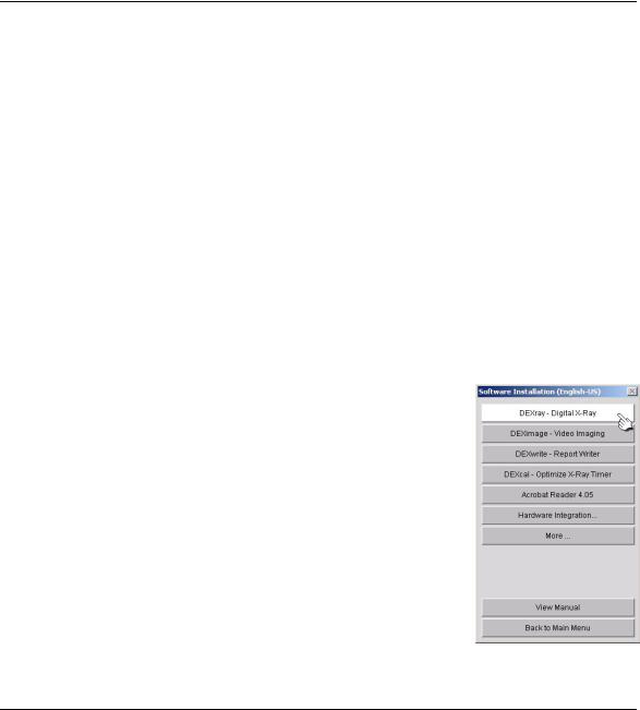
Select your language
If your CD offers the choice, choose“English-US,” as international versions give international tooth numbers that differ from those used in the US. The Software CD for distribution in the US does not offer this choice and automatically advances to the next step.
Select software
Click on “DEXray” to install the DEXray program.
Choose destination location
During the installation process you will be asked for the folder into which the software should be installed. Typically you should accept the default folder,
13

Chapter 2 |
Installation, Care, and Maintenance |
which is “C:\DEXIS\.” In any event, this must be a folder on a local hard disk, not on a network drive.
Note: If this is an upgrade from a previous DEXIS version, please make sure to install the latest version into the same folder as the older version. It will write over the existing version and will not disturb your data. Do not uninstall the older version unless requested to do so by DEXIS Technical Support.
Select data directory
Next, you will be asked where you would like to store DEXIS data. Typically, this will be “C:\DEXIS\Data” for a non-networked computer. In a network, this will be “C:\DEXIS\Data” on the server and “X:\DEXIS\Data” (or “\DEXIS\Data” on any other drive) on the client workstations.
Note: If you installed DEXIS on the server first and mapped the drive properly, the correct shared data folder will be automatically suggested by the installation program.
Follow the on-screen directions until DEXray is successfully installed.
Install additional software
Next, install DEXimage and DEXwrite using the previous method. It is strongly suggested that you load these two modules even if you have not purchased them. You will have a 30-day trial period to use and evaluate them.
14
Chapter 2 |
Installation, Care, and Maintenance |
Install other software only as it applies to your practice and purchased modules. Please call our telephone support professionals for assistance.
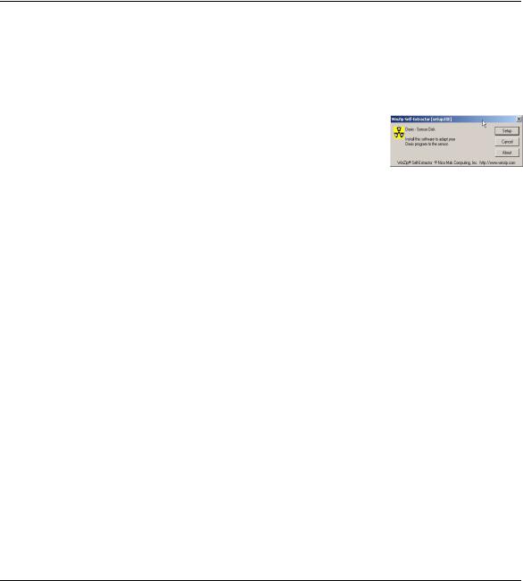
2.4.5 Installing the Sensor Disk
The Sensor Disk contains data specific to your particular sensor. It is used by the DEXray software to maximize the image quality.
1.Place the floppy disk labeled “Sensor Disk” into your floppy drive.
2.Go to “Start”, and then “Run”.
3.Type “A:setup” (“A” in this case corresponds to your floppy drive letter) in the window and click “OK”.
4.When the next screen appears, click on “Setup”.
5.Follow the onscreen instructions to complete the installation.
Note: Repeat this process on all workstations where X-rays are to be taken.
Special instructions for offices with multiple sensors
Each sensor is numbered with a unique identifier. This ID number is listed and color-coded in the X-ray capture window once the sensor software is loaded. Install all of the sensor disks on each and every computer and in order. Label each sensor/board assembly with its appropriate number/color. Now, you will be able to use any sensor on any computer by selecting the sensor from the X- ray capture window, see “Taking X-Ray Images” on page 48.
2.4.6 Installing a link to your Practice Management Software
To utilize a link to Practice Management software, you must have a networked system. If you have a non-networked system, please skip this section.
Practice Management-provided Link
If you have a link purchased from your practice management company, please consult their Technical Support for assistance with installation and verification of the link, and directions for its use.
15
Chapter 2 |
Installation, Care, and Maintenance |
DEXIS-provided link
Please contact our Technical Support for assistance with the installation and verification of the link. Do not attempt to install without assistance as this could cause corruption of your existing patient database.
See “DEXIS to Dentrix Link” on page 128 and “DEXIS to EagleSoft Link” on page 130 for instructions for the use of DEXIS-provided links.
2.4.7 Adding Initial Information
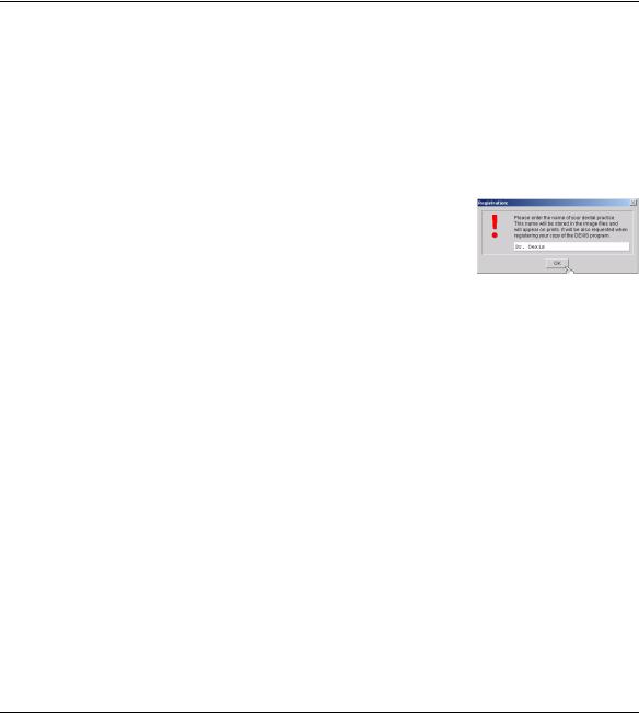
Once DEXIS is installed you will find a DEXIS icon on your desktop.
To initiate the DEXIS Administration program, double-click on this icon. A window will appear asking for your Practice Name. Type the name exactly as you want it to appear on printouts. Click “OK” when done.
16
Chapter 2 |
Installation, Care, and Maintenance |
Next, you will be asked to enter your telephone number. Type it in and click “OK.”
Now, you will be asked to enter a new patient. For setup and test purposes, enter a test patient. Type in a number (such as “1”), a last name (such as “Test”), and a first name (such as “Test”). Click “Done.” You will now have full view of the DEXIS Administration screen, and patient’s name, Test Test, will appear on the screen.
For network systems, this initial information should now be accessible across the network and will not need to be added to each workstation.
If linked to a practice management software:
All patients must be added through your practice management software. However, you may add a test patient directly into DEXIS Administration (see above) to be deleted after testing. Alternatively, you may add a test patient within your Practice Management or choose to use an existing patient’s file with which to practice. See “DEXIS to Dentrix Link” on page 128 and “DEXIS to EagleSoft Link” on page 130 for instructions on the use of DEXIS-provided links.
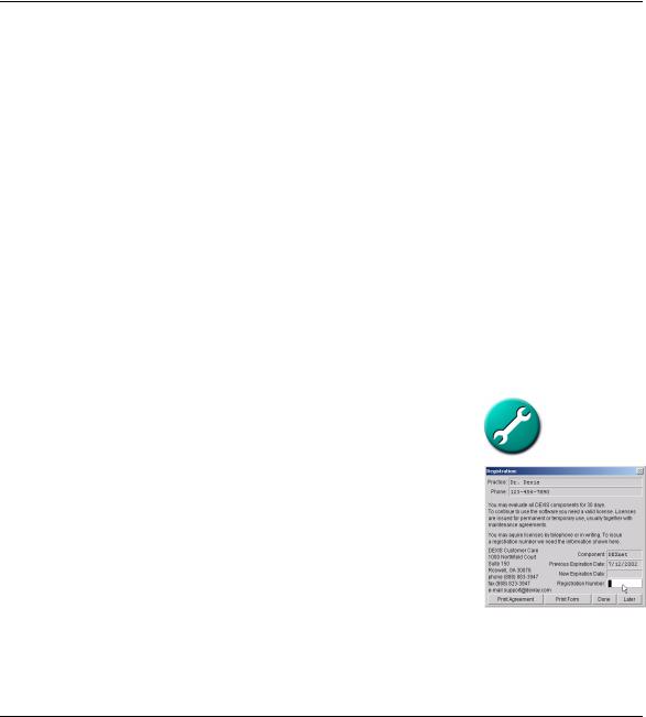
2.4.8 Obtain Registration Codes
From the DEXIS Administration screen, click on the “wrench” icon and then click on “Component Licensing”. Call DEXIS Technical Support for registration codes for your purchased programs. One of our technical representatives will walk you through the process. Should you wish to make any changes to your practice name or telephone number you will need to re-register your programs.
For network systems, you may obtain registration codes on any one workstation for the entire network.
Your DEXIS installation is now complete. Please go to “Installation Verification and Testing” on page 114 for verification and testing.
2.5Adjusting the X-ray Source
The following is a suggested method of setting up your X-ray machine in order to effectively take a digital radiograph. Each X-ray machine may be somewhat
17

Chapter 2 |
Installation, Care, and Maintenance |
different and may require more or less radiation in order to satisfy the doctor’s needs.
Clinical experience has shown that it is a safe bet that you can reduce the radiation by approximately 70% as a starting point if you are using D speed film or by 30% if you have already changed to E speed film. With E speed film you have already reduced the radiation significantly and therefore your savings with digital radiography will be less than with D speed film.
Remember that these settings will be different for anteriors (less exposure needed) and posteriors (more exposure needed). You should take several test images and then adjust the settings accordingly.
The radiation of X-ray tubes is controlled by the settings of:
•Voltage (kV or kVp)
•Current (mA)
•Exposure time (msec) or pulses
Some controls allow for the modification of all of the above, some have fixed settings for current and/or voltage. Although many newer X-ray units have a ‘Digital’ button, pressing it generally results in a flat reduction in radiation and may not be an ideal setting.
Starting from the settings you use for D speed film, you should modify the settings as follows: Keep the mA setting.
If possible, turn the kV or kVp down to 70. Some practices use voltages up to 90 kVp for film X-rays. These high settings give less contrast in digital X-rays. A reduction by 10 cuts the radiation in half. This has to be taken into consideration when adjusting the time.
Adjust the time or pulses so that the resulting radiation is about 1/3 of the one used for film. Take into account the reduction in voltage, if applicable.
No kVp reduction: reduce time by 60 - 70% kVp reduction by 10: reduce time by 30% kVp reduction by 20: leave time at film value kVp reduction by 30: double the time
18

Chapter 2 |
Installation, Care, and Maintenance |
Distance of X-ray source to the sensor
There is a correlation between the distance of the cone to the sensor and the resolution of the captured image. The radiation that reaches the sensor decreases with the square of the distance. That means if you double this distance, you receive only ¼ of the radiation. Be sure to place the cone as close to the patient’s face as possible. If you are using the PositionIt parallel ring, place the ring against the patient’s face and the cone against the ring.
Please note: X-ray machines, even the same brands and types purchased at the same time, differ widely in their performance. In addition, on newer X-ray machines, the “digital” setting on your dial or keypad may not be the ideal setting. We suggest that you test each machine in order to calculate the proper setting for that machine.
Selecting an Initial Setting
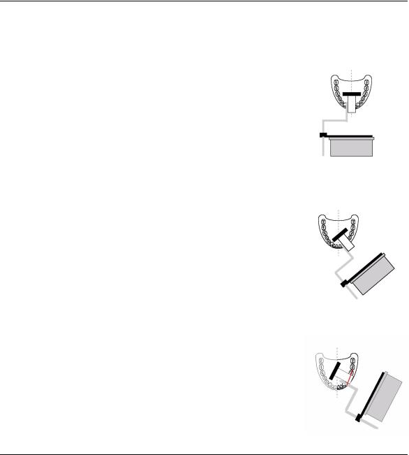
You need to take a few test X-rays with the calculated setting and critically review the images. Connect the sensor to the computer. Place your sensor into the aluminum testblock and place it on a flat surface with the testblock facing up. Aim your X-ray tube so that the long axis of the tube is perpendicular to the flat surface of the testblock. The X-ray head should be directly over the testblock, not more than 1/2 inch away from it.
Choose or create a test patient and open this patient’s DEXray intra-oral screen. Type “X” on your keyboard to open the Intra-oral X-ray Acquisition screen. Select a tooth from the chart. Yellow, then green bands will appear on the tooth chart. Leave the room and trigger the tube.
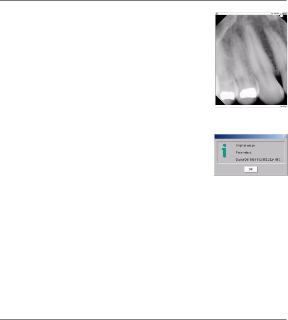
The DEXray software shows you the enlarged X-ray of the testblock. It looks rather dull, but since the testblock has a similar radiographic density as an average adult molar, the characteristics of the image will indicate whether the exposure is appropriate for X-raying teeth. Two tools help you in evaluating the test image:
Color indicator: The appearance of color indictors in the form of dots offers exposure information at a glance. If you receive a yellow dot, your level of radiation is too low. If you receive a red dot, your level of radiation is much too low. If the dot is blue, the level or radiation is too high. If the dot is black, the level of radiation is much too high.
19
Chapter 2 |
Installation, Care, and Maintenance |
Parameters: Each image has a group of numbers associated with its exposure. Check the parameters of the enlarged testblock image on the screen by clicking in the space between the date and the tack or on the color dot, if present. This opens the Image Parameters information box. The second number from the end (disregarding numbers in parentheses) is the one to look at. If that number is under 1500, raise the duration setting (seconds or pulses) and test again. If the parameter is over 2500, lower the duration setting and take another test X-ray. If the number is between 1500-2000, note the exposure setting for taking X-rays on anteriors. If between 2000-2500, note the exposure setting for taking X-rays on posteriors..
Note: Since the afore-mentioned parameter is a measure on how much radiation reaches the sensor, its value depends on the radiation issued by the tube, on the distance between the tube and the sensor, and on the object being X- rayed. The above given numbers are only valid for X-raying the DEXIS testblock. When you X-ray actual teeth, you will usually receive a higher parameter value because part of the X-ray shows "empty" space around and between the teeth that is not absorbing much radiation. As a rule of thumb, the parameter value (second last number disregarding numbers in brackets) is between 2500 and 3000 on well-exposed intraoral X-rays.
Evaluating Images
Use the setting established with the testblock to capture your first images on patients.
Initially, upon taking images on actual patients, please take the time to critically evaluate the image quality. If images appear grainy, increase the radiation by increasing the time. If they seem rather dark, you should reduce radiation. There is a wide range in which DEXIS compensates for underand over-exposure. If you get good results with a particular setting, you might try less radiation to see whether you still gain good results.
Remember, as with standard film, you will need to adjust the duration setting to compensate for tooth type (central incisor to molar) and body type (larger adult to small child)
The settings you ultimately choose, no matter the setting number or parameter it gives, should be what you consider to be suitable for your diagnostic needs.
Click on the color dot in the upper right corner.
20
Chapter 2 |
Installation, Care, and Maintenance |
2.6Safety Procedures with X-Rays
The rules of dental radiography still apply to digital X-ray systems. Although there is less radiation with digital X-rays, please continue to use protection for your patients. As a clinician, clear the immediate area when exposing the sensor.
When beginning to take DEXray images, please use the guidelines in “Taking X-Ray Images” on page 48. Only take X-rays on patients once you have adjusted your X-ray exposure and taken test images.
2.7Proper Care of the DEXIS Hardware
The sensor, cable (or cord) and board comprise the heart of the DEXIS system. Please treat your sensor and board with the care and respect afforded to other very sensitive electronic devices, such as digital cameras or laptop computers. The system is extremely important to your practice and productivity; it replaces your film, processor and darkroom. Please adhere to these important guidelines to keep your DEXIS system running at optimum levels.
2.7.1 Sensor and Board Care
•Never soak the sensor in any solution. Soaking and using caustic chemicals will weaken the sensor housing and the sensor-cable connection. Never expose the board to moisture. Also, Never autoclave the sensor or board.
•Never use hemostats or "clamping" devices on the sensor or cable. Doing so will cause sensor housing or cable wiring damage.
•Never twist, tightly coil, or wrap the sensor cable around any objects. This includes coiling it around the sensor board when not in use. Also, keep the sensor cable off the floor where chairs or carts may roll over the cable. In addition, keep the sensor cable clear of drawers and doors where it may be crimped upon their closing. Lastly, never pull or stretch the cable including when disconnecting the sensor from the board or removing barriers. Exposing the sensor cable to these situations will damage the sensor cable causing the sensor to pre-fire, give an unclear image or render it fatally damaged.
•Never allow patients to bite the sensor or cable. This will damage the housing and/or cable and lead to a sensor malfunction. We strongly recommend
21

Chapter 2 |
Installation, Care, and Maintenance |
the use the DEXIS holders as they are designed to protect the sensor; In addition, latex barriers, may give added protection. Should you choose to NOT use a DEXIS holder, you must protect the cord.
•Never insert foreign objects into the board or sensor connection housing. Doing so will cause a short in the sensor pins and will loosen, and/or damage the connection site.
•Never drop your sensor or board. Dropping the sensor, especially on hard surfaces such as floors and countertops, will shock the system causing the internal electronics to malfunction or be fatally damaged.
•Remove the sensor's board from the computer when re-starting the computer, whether during the day or overnight. If the computer is started with the board in the in PCMCIA slot, it is subject to power fluctuations that may cause circuitry issues. In addition, always remove the board from the computer before attaching or detaching the sensor.
•Protect the sensor and board. When the sensor/board are not in use, contain it in a way that will keep it from any conditions that can cause damage.
Please be advised: DEXprotect does not cover abuse or misuse. All visible damage voids your DEXprotect coverage and warranty.
2.7.2 Connecting your Sensor and Board to the computer
The sensor is connected to the PC Card by a metal connector. This is a precise connection. Therefore, please take the time to learn how this component functions. To separate the sensor from the board, pull them straight apart without twisting or turning either part. Once the two are separated, you may cover the sensor’s connection end with the attached cap.
To connect your sensor to the board, align the red dots on the two parts. Snap the parts together firmly until you hear a click.
Carefully insert the sensor/board assembly into the PCMCIA slot of your computer. Please use caution, as there may be 2 slots – keep it level and insert into one slot or the other. In most cases, you will hear two beeps. This is the signal that your computer recognizes the board. Additionally, you may hear two beeps each time you remove the board.
22
Chapter 2 |
Installation, Care, and Maintenance |
Please note: The DEXIS PC Card (or board) is “hot-swappable” meaning that you do not have to notify Windows that you plan to remove it. Nor do you need to restart your computer upon inserting the card. Should you receive a message that you “may lose valuable data” by removing hardware with out notifying Windows, please disregard. This does not pertain to the DEXIS card. The only time you should not remove the card is when the “Intra-oral X-Ray Capture” screen is open.
2.8Regular Backups of Image Files
It is extremely important to back up your data on a regular basis as a matter of routine maintenance. DEXIS offers DEXsafe, a one step feature to copy all or part of your DEXIS data to a specific backup drive. Please see our hardware requirements for recommendations on devices. Instructions for using DEXsafe are found in“Backing Up Your Image Files” on page 131.
23

Chapter 3 |
Clinical Use of the DEXIS Sensor Holders |
Chapter 3
Clinical Use of the DEXIS Sensor Holders
Please become acquainted with your sensor. The DEXIS sensor has a unique design; it has clipped corners and is thicker than film. This design, along with proper placement, translates into patient comfort. The electronics are in the bubble on the back, thereby utilizing nearly the entire surface of the sensor for capture. You receive an image approximately equivalent to #2 size standard film.
If you have not done so, please take some time to review the proper handling guidelines in “Proper Care of the DEXIS Hardware” on page 21 before attempting to use your DEXIS sensor.
3.1Overview of the Position-It System
The holders contained in your Position-It kit consist of:
•2 posterior biteblocks
•2 anterior biteblocks
•2 periapical rings and bars
•2 vertical bitewing biteblocks
•2 horizontal bitewing biteblocks
•1 bitewing bar and ring
•2 vertical endo holders
•2 horizontal endo holders
•2 cable clips
The bars, biteblocks and rings are similar to the RINN or XCP system and function in the same manner. The bitewing holders may be used with or without the bars and rings, or you may use bitewing tabs (along with cord protection). The periapical holders may be used alone or with the rings and bars. When the pe-
24

Chapter 3 |
Clinical Use of the DEXIS Sensor Holders |
riapical holders are used without the rings, they function as “stab” device. The hand-held endo holders may be used with or without the bitewing ring and bar.
The sensor will only fit into the holder one way. Assemble the rings, bars and holders so that the entire sensor area is visible through the ring. This applies to horizontal or vertical bitewing holders, periapical (anterior or posterior) holders, and endo holders.
Place the cord into the groove on the holder. This protects it when the patient closes. Should you choose to use the cable clip, place the square hole on the end of the bar and place the sensor cable into the clip.
3.2Correct Placement Using the Paralleling Technique
We recommend the use of the DEXIS Sensor Holders contained in the “Posi- tion-It System” included with your new DEXIS Digital X-ray System. Correct placement of the DEXIS sensor in the patient’s mouth is essential for obtaining acceptable X-ray image quality. These holders have been specially designed to work with the DEXIS Sensor and the DEXray software.
Please note: Holders shipped after January 1, 2003 are autoclavable, provided you use care and avoid direct contact with metal heating elements. These elements get very hot and direct contact will reduce the lifetime of your holders. Holders shipped prior to this date may be autoclaved but are more sensitive to overheating. Avoid direct contact with heating elements and do not expose to temperatures above 257° F/125° C.
The DEXIS sensor in combination with the supplied rings and holders (PositionIt Kit) use the paralleling technique originally developed by the Rinn™ Corporation. This technique places the sensor in the mouth so that it is parallel to the long axis of the tooth and perpendicular to the interproximal spaces. By drawing an imaginary line through the occlusal/incisal surfaces (occlusal line) of the teeth to be X-rayed, and placing the sensor parallel to this line, it will be perpendicular to the interproximal spaces. To achieve parallel positioning, the sensor/holder must be positioned away from the lingual/palatal surface and located in the deeper areas of the mouth in all areas except for mandibular molars.
25
Chapter 3 |
Clinical Use of the DEXIS Sensor Holders |
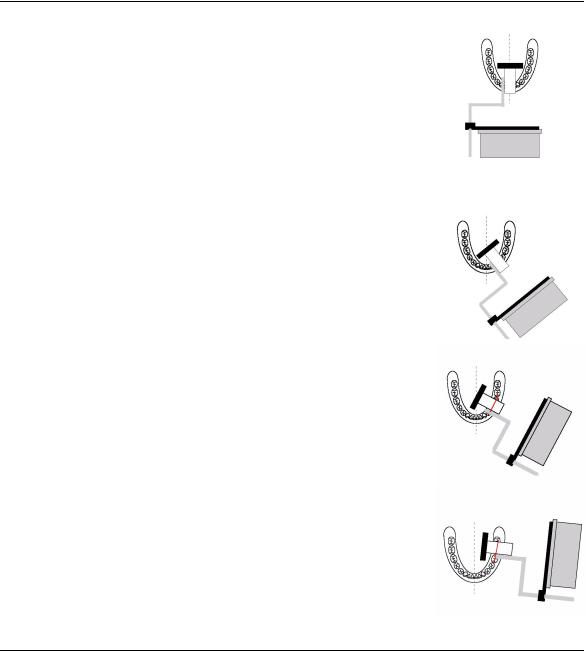
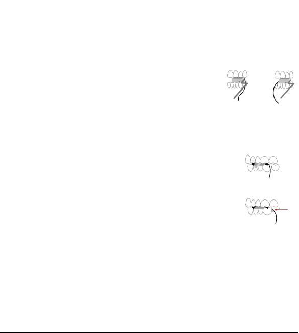
Mandibular Incisor
Position .the sensor/holder so that it is parallel to the roots of the mandibular incisors. Place either under the tongue or over the tongue, whichever is most comfortable for the patient. If large mandibular tori are present, position the sensor/holder behind the tori, even if it is in the first molar area. Ask the patient to close end-to-end in order to maintain the placement. In the event that the holder does not remain parallel to the roots of the incisors, bisect your angle. Should the incisal edges routinely be missing from your images, place a cotton roll or flap between the tooth and the holder and/or verify that the sensor holder is parallel to the roots.
Mandibular Canine or Cuspid
Position.the sensor/holder so that it is parallel to the roots of the mandibular canine. Place either under or over the tongue, whichever is most comfortable for the patient. If large mandibular tori are present, position the sensor/holder posterior to the tori, even if it is in the first molar area. Ask the patient to close end-to-end in order to maintain the placement. In the event that the holder does not remain parallel to the roots of the canine, bisect your angle. Should the incisal edges be routinely missing from you images, place a cotton roll or flap between the tooth and the holder and/or verify that the sensor holder is parallel to the roots
Mandibular Premolar or Bicuspid
Position the sensor/holder so that it is parallel to the roots of the mandibular premolars. Place either under or over the tongue, whichever is most comfortable for the patient. Once you establish that the sensor/holder is parallel to the roots and parallel to the occlusal line, move the sensor/holder to the midline. Ask the patient to close. In the event that the holder does not remain parallel to the roots of the premolars, bisect your angle.
Mandibular Molar
Position the sensor/holder so that it is parallel to the roots of the mandibular molars. Place between the tongue and the teeth. Once you establish that the sensor/holder is parallel to the roots and parallel to the occlusal line, ask the patient to close. This is the only position that does not require placement in the
26
Chapter 3 |
Clinical Use of the DEXIS Sensor Holders |
midline for comfort. In the event that the holder does not remain parallel to the roots of the premolars, bisect your angle.
Maxillary Incisor
Position the sensor/holder so that it is parallel to the roots of the maxillary incisors. Once you establish that the sensor/holder is parallel to the roots, move the sensor/holder toward the center of the palate. Ask the patient to close end- to-end in order to maintain the placement. In the event that the holder does not remain parallel to the roots, bisect your angle. If a large maxillary torus is present and you are unable to place the sensor/holder in a traditional position, the sensor/holder must be placed on the torus as you would place traditional film and you must bisect you angle. Should the incisal edges be routinely missing from you images, place a cotton roll or flap between the tooth and the holder and/or verify that the sensor holder is parallel to the roots.
Maxillary Canine or Cuspid
Position the sensor/holder so that it is parallel to the roots of the maxillary canine. Once you establish that the sensor/holder is parallel to the roots, move the sensor/holder toward the center of the palate. Ask the patient to close end- to-end in order to maintain the placement. In the event that the holder does not remain parallel to the roots, bisect your angle. If a large maxillary torus is present and you are unable to place the sensor/holder in a traditional position, the sensor/holder must be placed on the torus as you would place traditional film and you must bisect you angle. If the incisal edges are routinely missing from you images, place a cotton roll or flap between the tooth and the holder and/or verify that the sensor holder is parallel to the roots.
Maxillary Premolar or Bicuspid
Position the sensor/holder so that it is parallel to the roots of the maxillary premolars. Once you establish that the sensor/holder is parallel to the roots and parallel to the occlusal line, move the sensor/holder toward the center of the palate. Ask the patient close. In the event that the holder does not remain parallel to the roots, bisect your angle. If a large maxillary torus is present and you are unable to place the sensor/holder in a traditional position, the sensor/ holder must be placed on the torus as you would place traditional film and you must bisect you angle.
27

Chapter 3 |
Clinical Use of the DEXIS Sensor Holders |
Maxillary Molar
Position the sensor/holder so that it is parallel to the roots of the maxillary molars. Once you establish that the sensor/holder is parallel to the roots and parallel to the occlusal line, move the sensor/holder toward the center of the palate. Ask the patient to close. In the event that the holder does not remain parallel to the roots, bisect your angle. If a large maxillary torus is present and you are unable to place the sensor/holder in a traditional position, the sensor/ holder must be placed on the torus as you would place traditional film and you must bisect you angle.
Bitewing - Premolar or Bicuspid
Position the sensor/holder so that it is parallel to the occlusal line, move the sensor/holder toward the midline. Ask the patient to close.
Bitewing – Molar
Position the sensor/holder so that it is parallel to the occlusal line, move the sensor/holder toward the midline. Ask the patient to close.
Endo Holders
You may use the bitewing bar and ring with the endo holder to use the paralleling technique. Position the sensor/holder so that it is parallel to the root of the tooth and toward the midline. Ask the patient to grasp the handle after you have placed the sensor in the appropriate position. The patient may close to stabilize if position permits. The patient will not be able to close completely due to the design of the holder. Should you choose not to use the paralleling technique, bisect your angle.
28
Chapter 3 |
Clinical Use of the DEXIS Sensor Holders |
3.3Cord Protection
There is a groove on the underside of the periapical biteblocks and a slightly different groove in the bitewing biteblocks. Place the sensor cord into this groove for protection. This works well when the sensor is placed into the holder and then the entire assembly is sleeved.
On those occasions where it is necessary to sleeve the sensor before placing in the holder, due to the thickness of the barrier, the cord may not stay in the groove. In this case, verify that the cord is adjacent to the holder, either to the side that is to the anterior or posterior of the biteblock. Since the biteblock will not allow for full closure, the cord is protected. Again, please verify that the cord is not between the biteblock and the teeth as it may become crimped upon the patient closing.
We strongly recommend the use of the DEXIS holders as they are designed to protect the sensor and cord. However, should you choose not to use the DEXIS holders, you must take steps to protect the sensor and the cord. The use of latex barriers and sponge bw tabs may offer additional protection. However, no matter the barrier or bw tab, you must protect the cord
You must always ask patients to close "lightly" so that they have only the slightest of contact. Do not allow patients to depress the cord. If you feel that you will not have the patient's full cooperation, place an object such as a folded gauze or cotton roll on the tab, to hold the teeth open just enough to keep the cord from harm. You may also place the cord in an area where there are missing teeth or in an area where, anatomically, there is an open space or lack full occlusion.
3.4Barriers and Protection
There are many types of barriers that you can use with your sensor, and other hardware. Sensors must be covered with some type of barrier that covers the sensor and at least 3”– 4” of the cable. Barriers made of latex, urethane or plastic (such as a handpiece sleeve) are widely available. Keyboards may be covered with pre-formed plastic covers or plastic wrap. Use a baggie or a lowtack light handle sheet to cover the mouse. Low-tack light handle covers also work well for barriers for laptop touch pads. Use sterile barriers for surgical settings.
29

Chapter 3 |
Clinical Use of the DEXIS Sensor Holders |
Cleaning and Decontamination of the Sensor and Holders
To comply with ADA and CDC guidelines on decontamination, you must follow these steps: First, sleeve your sensor with an appropriate barrier, place into the holder and change the holders as needed. When you complete your images, remove and discard the barrier. Use a hard-surface disinfectant spray or pop-up wipe on the sensor and cord. Always use a solution that does NOT contain bleach, glutaraldehyde, alcohol, or other strong chemical components. Your sensor may be washed with warm water and soap, if necessary.
Sterilize/Decontaminate your holders. Please note: The current DEXIS sensor holders are autoclavable, however, certain restrictions apply:
•Always avoid direct contact of the holders with metal trays, instruments, and heating elements.
•Always place holders in autoclave bags
•Always situate bagged holders into the autoclave so that they are furthest from the heat source.
Exposing the holders to hot metal and placing them close to heating elements will reduce the lifetime of the holders.
Older versions of the holders are more sensitive to overheating. Decontaminate these holders using a cold sterile solution. Please consult the manufacturer's recommendations for the solution you are using.
Should you use only one holder for a patient’s procedure, you may cover the entire assembly with a barrier. However, decontamination is as previously described: Use hard surface disinfectant on the sensor and decontaminate/sterilize your holders.
Please decontaminate you new sensor and holders prior to use.
Please note: Should you have any questions regarding the decontamination of your sensor and holders, contact our Customer Care Center.
30
Loading...