

Page 1

User’s Manual
Software Release 5
Page 2

Chapter 1 Introduction
Chapter 1
Introduction
1.1 Welcome to DEXIS
Welcome to the exciting world of DEXIS! And thank you for your recent investment in the DEXIS Digital X-ray System. We hope you will have an extraordinary
experience with our products and services.
Our mission at DEXIS is to develop and support the Digital Radiography community around the world. We seek to build strong partnerships with our doctors and their teams based on long-term, interactive relationships.
Your new DEXIS Digital X-ray System was designed from the outset with you,
the clinician, in mind. This is your tool. Learn to use it well and it will become
an effective aid in your diagnosis, treatment and treatment planning process.
As with all new clinical tools, it is necessary to invest a certain amount of time
for practice in order to become proficient with the DEXIS Digital X-ray System.
We strongly recommend that you register for in-office training with a certified
DEXIS instructor and that you and all of your clinical team set aside 4 to 6 hours
to learn the system together. This manual is not intended to serve as a substitute for this training. However, as preparation for the training we do encourage
you to read the manual thoroughly and practice with it safely and carefully for
at least one week prior to your training date.
Please note that this manual assumes that new users possess basic computer
skills and an understanding of the Windows® operating system. Absent this
experience, we strongly recommend that you obtain these skills through a
computer course, video, or textbook. Your DEXIS representative may be able to
suggest (although not endorse) one or more of these computer learning resources.
®
Unless otherwise stated, in this manual “CLICK” refers to a single left mouseclick . Most functions in the DEXIS software require a single left click. Erroneous
or impatient double-clicking or right clicking may cause the program to func-
2
Page 3

Chapter 1 Introduction
tion improperly. Also, as a general request, please give the program time to
start and complete each function before clicking again.
Let’s start your journey into the world of DEXIS Digital X-ray!
1.2 What’s New in Release 5
This new release of the DEXIS software is a major update over previous releases. It is far and away the most comprehensive upgrade since the original software was introduced in 1995.
New 32-bit Software
The major improvement in this release is that the software has been completely rewritten line-by-line in 32-bit code.
The principal advantage of 32-bit software is that it should run much faster and
more reliably. In addition, there will be a wider range of hardware available to
interface with the software, including scanners and video cards.
Consistent with the new 32-bit architecture, the new release of DEXIS will now
run in “native” format with the new Microsoft operating systems: Windows®
XP® (home or professional) and Windows® 2000®.
This release also retains “backward compatibility” with earlier versions of Windows, including Windows® 98® and 95® Windows® NT®, and non-upgrade
versions of Windows® ME®.
New Patient Administration Screen
The DEXIS Patient Administration program has been modified and improved as
a result of requests from owners. The main window is now scaleable and a
scroll bar has been added. Font size can also be controlled. A few other functional changes were introduced with DEXIS release 3.1 and are incorporated
into this release, as well.
New Name: DEXray
The main DEXIS program has been renamed DEXray, consistent with its primary
function: taking and displaying digital X-rays. Other changes include subtle
3
Page 4

Chapter 1 Introduction
modifications to the layout, including title bar appearance and icons. Following requests from owners, the “corners” and outline of any new on-screen
“DEXrays” are now black instead of white (older images retain their original
white background, created when the X-ray was first acquired).
New designations
New designations have been introduced to assist in identifying the origin of image sources. These designations include “DEXray by DEXIS” for an original Xray image taken using a DEXIS sensor and DEXIS capture device. An X-ray taken
using non-DEXIS hardware but acquired directly into the DEXray program will
carry the designation “Original.” Additional designations that may appear include “Scanned,” “Imported,” “Derived,” and “Enhanced.”
These new designations are intended to provide greater security and reassurance with regard to the origin of images. They will be present whenever an onscreen image is enlarged or printed.
New Perio Mode ClearVu
The ClearVu image enhancement has been further refined to meet the needs of
periodontists: crisp bone structures and ligatures are obtained with a mouse
click. Furthermore, ClearVu mode now stays on when you switch patients. Also
the printed ClearVu has been optimized giving sharper printed images in
DEXray as well as in DEXwrite.
New Compare Feature
“Compare” is a new DEXray feature that allows the comparison of two images
in order to ascertain their differences.
The four modes: “Side By Side” offers the images side by side and proportional
in size; “Color Addition” shows density changes in color; “Subtraction” shows
density changes in light/dark values; “Red-Green Stereo” from earlier editions
is incorporated into “Compare.” The latter three modes allow for the alignment
of the two selected images. Originally designed for the research community,
“Compare” is now available to all DEXIS users.
4
Page 5

Chapter 1 Introduction
New DEXwrite Features
The chairside report generator DEXwrite has been extended in several respects: A generalized “Recepient” mechanism greatly simplifies sending reports to all kinds of recipients; reusable text blocks and input fields give
greater flexibility in report generation.
New DEXsafe Feature
DEXsafe, a feature that allows you to easily backup your data, is now offered.
DEXsafe is accessed from the DEXIS Administration screen. It allows you to
choose full or incremental backup and to choose a specific drive.
New Help Features
The screen now shows the current DEXIS logo as an icon that leads to the Program Information screen. This screen offers two new functions:
• Help: allows access to the DEXIS software on-screen manual
• DEXIS Web Site: opens the DEXIS web site in the user’s browser.
5
Page 6

Chapter 2 Installation, Care, and Maintenance
Chapter 2
Installation, Care, and Maintenance
Most telephone calls for assistance received by the DEXIS Customer Care specialists stem from inadequate attention to hardware and software installation.
Poor care of the DEXIS sensor or DEXIS capture device can result in damage to
or destruction of the fragile electronic components. Also, inattention to basic
maintenance procedures, including adjustment of the X-ray source, can lead to
unacceptable image quality.
We strongly recommend using the installation services of a factory-trained
DEXIS engineer or certified DEXIS installer. We also recommend that you engage a qualified computer specialist or an experienced network technician and
develop a permanent relationship for your ongoing computer needs. We understand the prospective of “saving money” by implementing a seemingly more
cost-effective solution; however, it is our experience that while this may be true
in the short term, such decisions are considerably more expensive in the long
run.
Naturally, turnover and attrition in a dental office will see team members come
and go. The DEXIS Digital X-ray System is a highly sophisticated piece of equipment that must be handled with care and maintained in accordance with the
manufacturer’s recommendations. Despite the pressures of a busy schedule,
please take the time to ensure that all new team members become familiar
with the equipment and the care that it requires.
After installing and testing your software, hardware and components, we suggest that you take the time to explore the software and read the on-screen manual.
When calling Technical Support for assistance, please make sure that you have
access to the computer on which the DEXIS system is used and on which the
manual may be displayed. You will be instructed where to find answers and solutions for your particular questions. This makes for optimal “over the phone”
assistance.
6
Page 7

Chapter 2 Installation, Care, and Maintenance
2.1 Overview of the DEXIS System
Upon opening your DEXIS kit you will notice three basic components: the DEXIS
sensor with its PC Card (also referred to as “PCMCIA Card,” “Mobile Card” or
“Board”), the DEXIS installation software and your full set of sensor holders.
2.2 Hardware Requirements
Our current hardware system requirements are available in the support section
on our website www.DEXray.com, from your representative and from our Customer Care Center. As technology changes, our requirements are updated to reflect such changes. Please consult current DEXIS systems requirements before
the purchase of any hardware.
2.2.1 Hardware Platform
This version of DEXIS software is for use on common PC platforms of the singleuser type, including those with networks, both desktop and laptop varieties.
The System Requirements for this software are the same as the minimum requirements stated for the operating system installed therein. Note that systems meeting only the minimum requirements may fail to deliver a satisfactory
experience. Systems with faster processors, more memory, and bigger, faster
hard drives will significantly enhance performance.
2.2.2 Operating System Platform
This software has been validated for use on the following members of the Microsoft Windows product family of operating systems:
• Windows 95 OSR2
• Windows 98 Second Edition
• Windows NT4 (see below for restrictions)
• Windows 2000
• Windows XP
Do not deploy this software for use on other versions of Microsoft Windows or
on other operating systems that emulate the Windows operating system un-
7
Page 8

Chapter 2 Installation, Care, and Maintenance
less the software has been validated for use on that platform by our Technical
Department.
Windows NT4 has only limited support for PC Cards; therefore, you need to install the software library “Cardware for Windows NT” in order to use the DEXIS
sensor. “Cardware for Windows NT” is commercially available. Most video capture cards are also not supported under Windows NT.
2.2.3 Caution: Hardware & Software Upgrades
Every change in hardware or software exposes your business to risk. Computers containing patient records are “mission critical.” Careful consideration is
required in order to minimize risk before changes are made to any system that
is currently in use. Whether the change is to be made to hardware, to the operating system or to the DEXIS application software, you should be prepared to
deal with an unexpected outcome including a catastrophic loss of data. For
this reason, we offer the following suggestions for use with mission-critical
systems:
Instead of upgrading hardware or operating system, consider purchasing a
new pre-configured system. Computers are amazingly inexpensive today;
bringing-up a new system in parallel with an existing system is a good way to
avoid placing the existing system at risk. The existing system will remain productive while the new system is qualified and readied for full service. Consider
the new computer as cheap insurance, but it’s even better than insurance because you get to keep it.
If you must upgrade your existing system, consider purchasing an additional
hard drive and making a bootable, literal copy of the existing hard drive. Remove the original hard drive and make the changes to the newer (and probably
larger) hard drive. With the original hard drive removed from the computer, it is
not at risk and all of your data will be safeguarded. If the new changes are
found to be unsatisfactory after a suitable evaluation period, you can always
re-install the old hard drive and fully restore your previous environment.
Always back-up your data and store it offsite. Before assuming that your backup efforts have been successful, make sure that you understand the backup
process and practice the restore process at least once on a test system. Verify
that both the operating system and data have been preserved.
8
Page 9

Chapter 2 Installation, Care, and Maintenance
2.2.4 Diagnostic Imaging
It is in displaying images on the screen that your needs dramatically depart
from the needs of ordinary computer users. The quality of image presentation
will be important in your selection of a monitor and video card. Carefully evaluate your selection prior to purchase by using sample images that are known
to be of diagnostic quality. Sample images, including a viewing program, are
available from your DEXIS Representative. DEXIS users can make their own
evaluation floppy by simply exporting with DEXview.
Here are a few things that we have learned after many years of experience:
• Premium monitors are highly recommended. Your needs are similar to those
of a professional image scientist or a commercial photographer, so treat
yourself to the best quality.
• Premium CRT-based monitors are still better than premium LCD-based monitors.
• A CRT monitor with an “Invar Mask” will be better than one with a mask of
any other material.
• Monitors with tiny tri-color dots are better than monitors with colors in
stripes or bars. You can examine the color arrangement with a loupe.
• Analog monitors seem to have better images than so-called digital monitors.
• When selecting a notebook computer, chose models with LCD screens recommended for use with photographic imaging.
2.2.5 Special Hardware Requirements
DEXray
The DEXray product requires a PCMCIA interface. These interfaces are also referred to as PC Card Readers. Most notebook computers include PC Card Readers while most desktop computers do not. It is not possible to add an external
PC Card Reader to a notebook computer that does not have one built-in. Approved PC Card Readers for desktop computers are available from your DEXIS
Representative. These accessories are easy to install and can be retrofitted to
desktop computers with one available 3.5” floppy disk drive bay and one avail-
9
Page 10

Chapter 2 Installation, Care, and Maintenance
able PCI or ISA card position (specify PCI or ISA). Please refer to the Hardware
and Software Installation section prior to installing this accessory.
DEXimage
DEXimage requires an image source and a capture device. The quality of the result cannot be better than the quality of the source. Expensive cameras may offer higher resolution still images at low frame rates, while full-motion video
cameras may capture dozens of frames per second, none of them high resolution enough to allow enlargements.
Capture devices may be interfaced directly to boards installed in the back of
the computer, or to interfaces like USB. The interface you choose may affect the
performance or usability of the result. Ease of use is also important. A product
that requires the user to transfer images from camera to computer in order to
send images may be less usable than a product that transfers images in a
“hands free” fashion.
Always test your camera installation as a “stand-alone” before interfacing to
DEXimage.
A foot pedal can be used in DEXimage to start and stop the live video and to
capture still pictures. DEXimage can handle foot pedals connected to a serial
port and pedals connected to a game port. Some cameras have a capture button that can be used instead of a serial port foot pedal.
DEXscan
DEXscan requires a scanner. To scan ordinary paper images, such as your signature or office logo, a standard scanner may be used. If you intend to scan Xray images a scanner with a transparency adapter is required. Be sure to select
a scanner that is recommended by DEXIS and that has an interface that is appropriate for your installation.
2.3 Hardware Installation
2.3.1 PC Card Reader Installation
Install the PC Card reader (PCMCIA slot) into your desktop computer following
the manufacturer’s instructions, typically the card reader’s software and then
10
Page 11
Chapter 2 Installation, Care, and Maintenance
the card reader itself. When you turn your computer on, Windows should recognize the reader and load the appropriate drivers.
If you do not receive the message “New hardware found” call Technical Support for assistance.
DO NOT PLUG THE DEXIS PC CARD IN AT THIS TIME!
2.3.2 DEXIS Provided Foot Pedal
Plug the foot pedal cable into the serial port on the back of your desktop or laptop computer (9 pin male connector). See “Foot pedal or Wand Capture” on
page 86 for instructions on how to use.
Please note: DEXIS provided foot pedals are for use with DEXimage software
only. They will not work with any other camera software.
2.3.3 Additional Hardware
Please refer to the specific owner’s manuals for information on your computers, printers, scanners, card readers, foot pedals, monitors, and cameras for
installation and use. Should you need technical assistance with any of these
items, please consult the manufacturer of each specific item.
Again, we strongly recommend employing the services of a factory-trained DEXIS engineer or certified DEXIS installer. We also recommend that you engage a
qualified computer specialist or (preferably) a network technician and create a
sustainable relationship for your ongoing computer needs.
2.4 Software Installation
Please follow these instructions to install your new DEXIS Digital X-ray System
software. Your DEXIS system must be completely installed and tested before
training can begin.
After installation, use the verification and testing instructions in “Installation
Verification and Testing” on page 114. Following all the instructions will ensure
that your system is fully functional. The system will be taught in the “Simulation” mode for all hardware not functioning at the time of training.
11
Page 12
Chapter 2 Installation, Care, and Maintenance
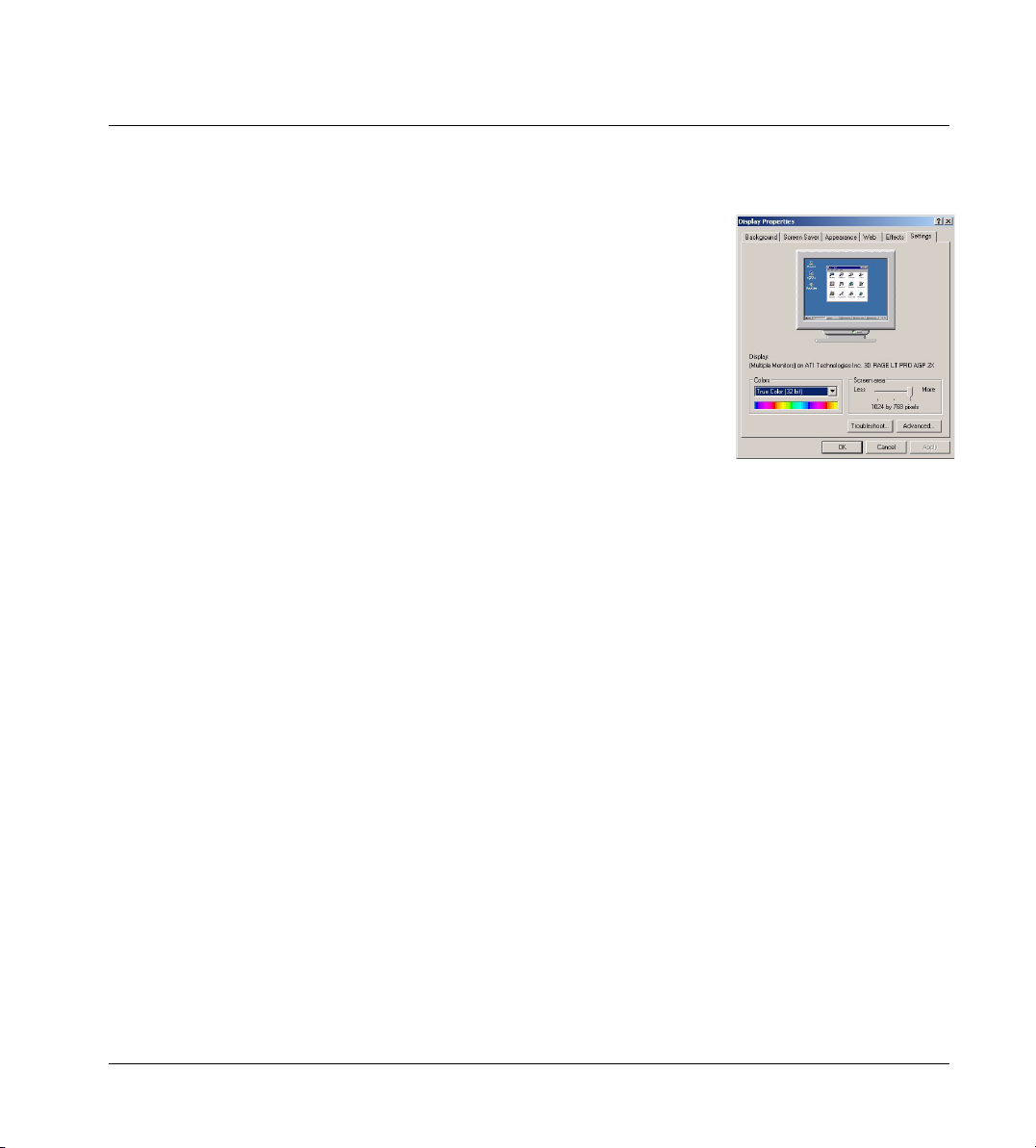
2.4.1 Display Settings
Before installing your DEXIS software, please change your display settings to
best view the DEXIS screens.
1. Go to: “Start”, then “Settings” and click on “Control Panel”; double-click
on the “Display” icon to open the Display Properties screen; click on the
“Settings” tab at the top.
2. Under Colors: Choose “True Color” (16-bit) for laptop computers and flat-
panel monitors. Choose 16-bit or 24-bit for all others.
3. Under “Screen area”: Recommended resolution is 1024 x 768, but the soft-
ware will also work on all other resolutions. Always choose the native resolution for LCD monitors.
4. Click on “Apply” to apply these settings.
2.4.2 DEXIS Installation CD
The DEXIS installation software is delivered to you on a CD plus an additional
floppy disk entitled “Sensor Disk.” This additional piece of software is used to
maximize the resolution of your sensor.
Plea se no te: If you purchased your computer through DEXIS, it will be de livered
to you pre-loaded with software and initial information. Please refer to “Installation Verification and Testing” on page 114 to skip the installation steps and
go directly to Verification.
2.4.3 Installation Planning
If you plan to run DEXIS on a stand-alone computer, there is not much to plan
and you may proceed to the next section.
If you have a local area network, you need to designate a hard disk of one of
the computers to hold the DEXIS data (images and patient data). This server
disk needs to be shared so that it can be accessed (with read and write access)
from all of the computers that will be running DEXIS software and will thus
need to access the data. It has to be given a drive letter on all participating
computers. We suggest the drive letter “X” (for X-ray), and will use this letter in
subsequent examples, although any other drive letter would be fine.
12
Page 13
Chapter 2 Installation, Care, and Maintenance
Note:
If these terms are unfamiliar to you, please STOP. DEXIS highly recom-
mends that you contact your network professional before proceeding further
For a network installation, the following steps have to be performed on all computers on which DEXIS software is to be used. Start with the server, where the
DEXIS data will be stored.
2.4.4 Running the Installation Program
To begin the installation, insert the DEXIS installation CD into your CD-ROM
drive. The CD is equipped with an “Autorun” feature and will start on its own.
Should the “Autorun” feature not work with the CD-ROM drive in your computer, you can launch the installation menu manually: Double-click on the “My
Computer” icon on your desktop, then open the CD-ROM drive by double-clicking on its icon, then double-click on the “DEXmenu” icon.
Select your language
If your CD offers the choice, choose“English-US,” as international versions
give international tooth numbers that differ from those used in the US. The
Software CD for distribution in the US does not offer this choice and automatically advances to the next step.
.
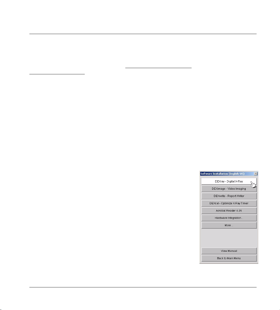
Select software
Click on “DEXray” to install the DEXray program.
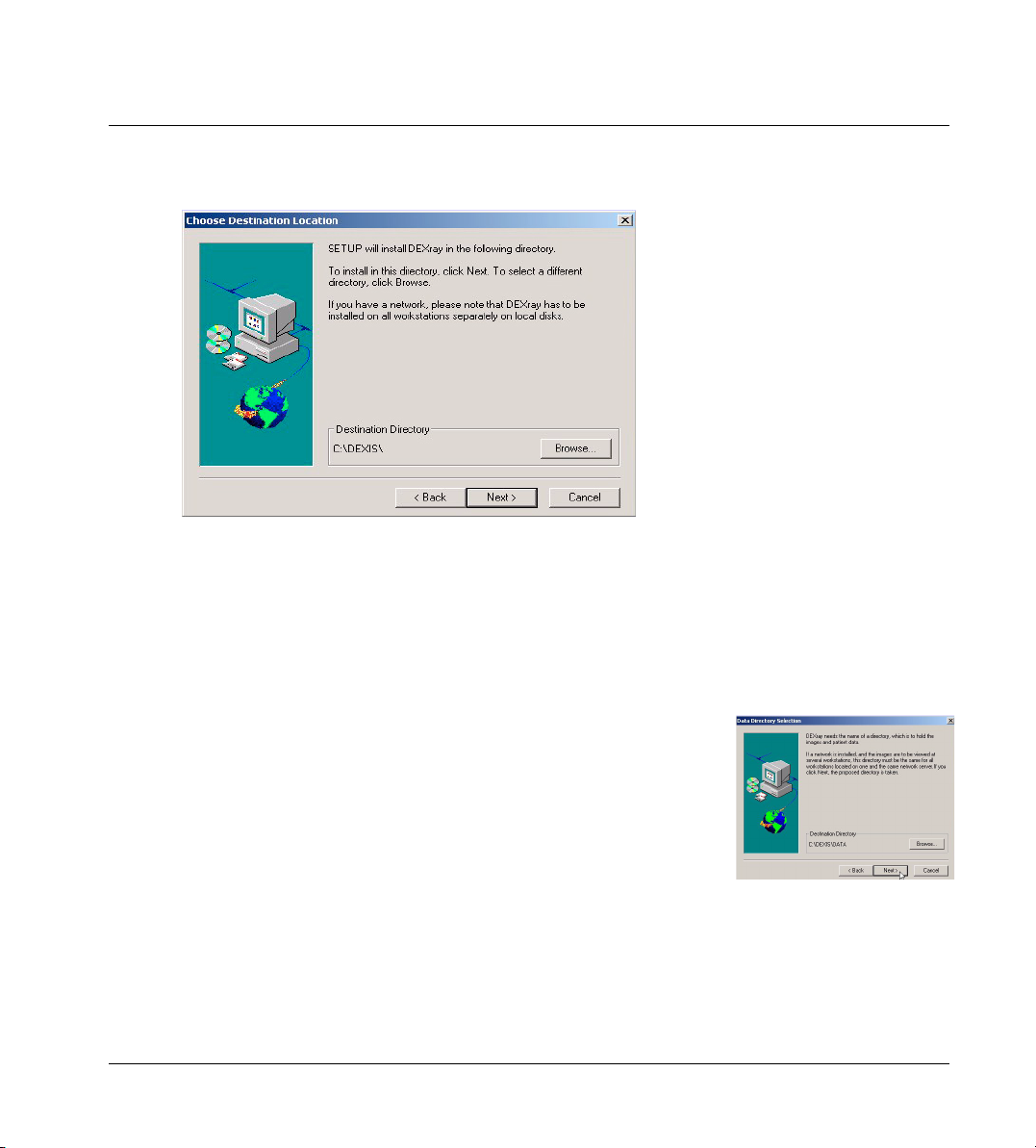
Choose destination location
During the installation process you will be asked for the folder into which the
software should be installed. Typically you should accept the default folder,
13
Page 14
Chapter 2 Installation, Care, and Maintenance
which is “C:\DEXIS\.” In any event, this must be a folder on a local hard disk,
not on a network drive.
Note: If this is an upgrade from a previous DEXIS version, please make sure to
install the latest version into the same folder as the older version. It will write
over the existing version and will not disturb your data. Do not uninstall the
older version unless requested to do so by DEXIS Technical Support.
Select data directory
Next, you will be asked where you would like to store DEXIS data. Typically, this
will be “C:\DEXIS\Data” for a non-networked computer. In a network, this will
be “C:\DEXIS\Data” on the server and “X:\DEXIS\Data” (or “\DEXIS\Data” on
any other drive) on the client workstations.
Note: If you installed DEXIS on the server first and mapped the drive properly,
the correct shared data folder will be automatically suggested by the installation program.
Follow the on-screen directions until DEXray is successfully installed.
Install additional software
Next, install DEXimage and DEXwrite using the previous method. It is strongly
suggested that you load these two modules even if you have not purchased
them. You will have a 30-day trial period to use and evaluate them.
14
Page 15
Chapter 2 Installation, Care, and Maintenance
Install other software only as it applies to your practice and purchased modules. Please call our telephone support professionals for assistance.
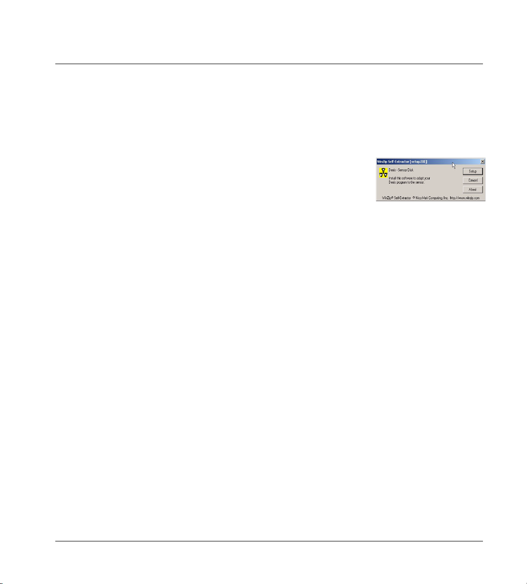
2.4.5 Installing the Sensor Disk
The Sensor Disk contains data specific to your particular sensor. It is used by
the DEXray software to maximize the image quality.
1. Place the floppy disk labeled “Sensor Disk” into your floppy drive.
2. Go to “Start”, and then “Run”.
3. Type “A:setup” (“A” in this case corresponds to your floppy drive letter) in
the window and click “OK”.
4. When the next screen appears, click on “Setup”.
5. Follow the onscreen instructions to complete the installation.
Note: Repeat this process on all workstations where X-rays are to be taken.
Special instructions for offices with multiple sensors
Each sensor is numbered with a unique identifier. This ID number is listed and
color-coded in the X-ray capture window once the sensor software is loaded.
Install all of the sensor disks on each and every computer and in order. Label
each sensor/board assembly with its appropriate number/color. Now, you will
be able to use any sensor on any computer by selecting the sensor from the Xray capture window, see “Taking X-Ray Images” on page 48.
2.4.6 Installing a link to your Practice Management Software
To utilize a link to Practice Management software, you must have a networked
system. If you have a non-networked system, please skip this section.
Practice Management-provided Link
If you have a link purchased from your practice management company, please
consult their Technical Support for assistance with installation and verification
of the link, and directions for its use.
15
Page 16
Chapter 2 Installation, Care, and Maintenance
DEXIS-provided link
Please contact our Technical Support for assistance with the installation and
verification of the link. Do not attempt to install without assistance as this
could cause corruption of your existing patient database.
See “DEXIS to Dentrix Link” on page 128 and “DEXIS to EagleSoft Link” on
page 130 for instructions for the use of DEXIS-provided links.
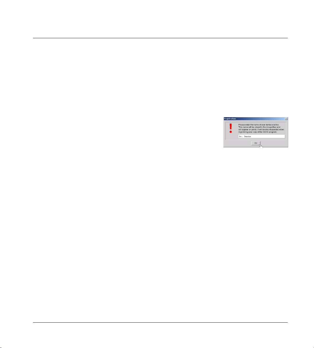
2.4.7 Adding Initial Information
Once DEXIS is installed you will find a DEXIS icon on your desktop.
To initiate the DEXIS Administration program, double-click on this icon. A window will appear asking for your Practice Name. Type the name exactly as you
want it to appear on printouts. Click “OK” when done.
16
Page 17
Chapter 2 Installation, Care, and Maintenance
Next, you will be asked to enter your telephone number. Type it in and click
“OK.”
Now, you will be asked to enter a new patient. For setup and test purposes, enter a test patient. Type in a number (such as “1”), a last name (such as “Test”),
and a first name (such as “Test”). Click “Done.” You will now have full view of
the DEXIS Administration screen, and patient’s name, Test Test, will appear on
the screen.
For network systems, this initial information should now be accessible across
the network and will not need to be added to each workstation.
If linked to a practice management software:
All patients must be added through your practice management software. However, you may add a test patient directly into DEXIS Administration (see above)
to be deleted after testing. Alternatively, you may add a test patient within your
Practice Management or choose to use an existing patient’s file with which to
practice. See “DEXIS to Dentrix Link” on page 128 and “DEXIS to EagleSoft
Link” on page 130 for instructions on the use of DEXIS-provided links.
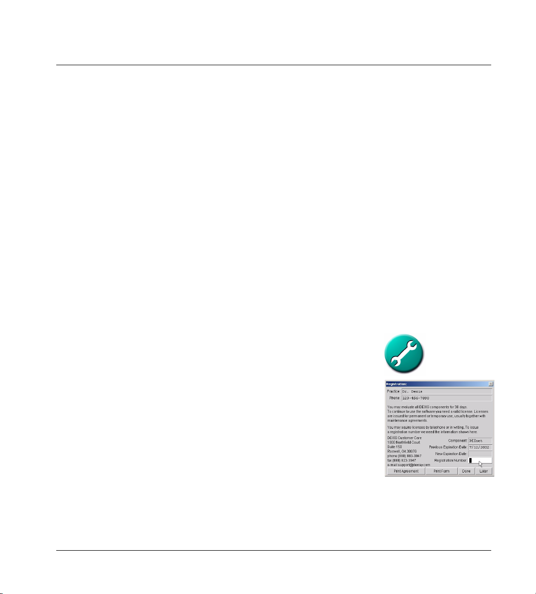
2.4.8 Obtain Registration Codes
From the DEXIS Administration screen, click on the “wrench” icon and then
click on “Component Licensing”. Call DEXIS Technical Support for registration
codes for your purchased programs. One of our technical representatives will
walk you through the process. Should you wish to make any changes to your
practice name or telephone number you will need to re-register your programs.
For network systems, you may obtain registration codes on any one workstation for the entire network.
Your DEXIS installation is now complete. Please go to “Installation Verification
and Testing” on page 114 for verification and testing.
2.5 Adjusting the X-ray Source
The following is a suggested method of setting up your X-ray machine in order
to effectively take a digital radiograph. Each X-ray machine may be somewhat
17
Page 18

Chapter 2 Installation, Care, and Maintenance
different and may require more or less radiation in order to satisfy the doctor’s
needs.
Clinical experience has shown that it is a safe bet that you can reduce the radiation by approximately 70% as a starting point if you are using D speed film or
by 30% if you have already changed to E speed film. With E speed film you have
already reduced the radiation significantly and therefore your savings with digital radiography will be less than with D speed film.
Remember that these settings will be different for anteriors (less exposure
needed) and posteriors (more exposure needed). You should take several test
images and then adjust the settings accordingly.
The radiation of X-ray tubes is controlled by the settings of:
• Voltage (kV or kVp)
•Current (mA)
• Exposure time (msec) or pulses
Some controls allow for the modification of all of the above, some have fixed
settings for current and/or voltage. Although many newer X-ray units have a
‘Digital’ button, pressing it generally results in a flat reduction in radiation and
may not be an ideal setting.
Starting from the settings you use for D speed film, you should modify the settings as follows: Keep the mA setting.
If possible, turn the kV or kVp down to 70. Some practices use voltages up to
90 kVp for film X-rays. These high settings give less contrast in digital X-rays. A
reduction by 10 cuts the radiation in half. This has to be taken into consideration when adjusting the time.
Adjust the time or pulses so that the resulting radiation is about 1/3 of the one
used for film. Take into account the reduction in voltage, if applicable.
No kVp reduction: reduce time by 60 - 70%
kVp reduction by 10: reduce time by 30%
kVp reduction by 20: leave time at film value
kVp reduction by 30: double the time
18
Page 19

Chapter 2 Installation, Care, and Maintenance
Distance of X-ray source to the sensor
There is a correlation between the distance of the cone to the sensor and the
resolution of the captured image. The radiation that reaches the sensor decreases with the square of the distance. That means if you double this distance, you receive only ¼ of the radiation. Be sure to place the cone as close
to the patient’s face as possible. If you are using the PositionIt parallel ring,
place the ring against the patient’s face and the cone against the ring.
Please note: X-ray machines, even the same brands and types purchased at
the same time, differ widely in their performance. In addition, on newer X-ray
machines, the “digital” setting on your dial or keypad may not be the ideal
setting. We suggest that you test each machine in order to calculate the proper setting for that machine.
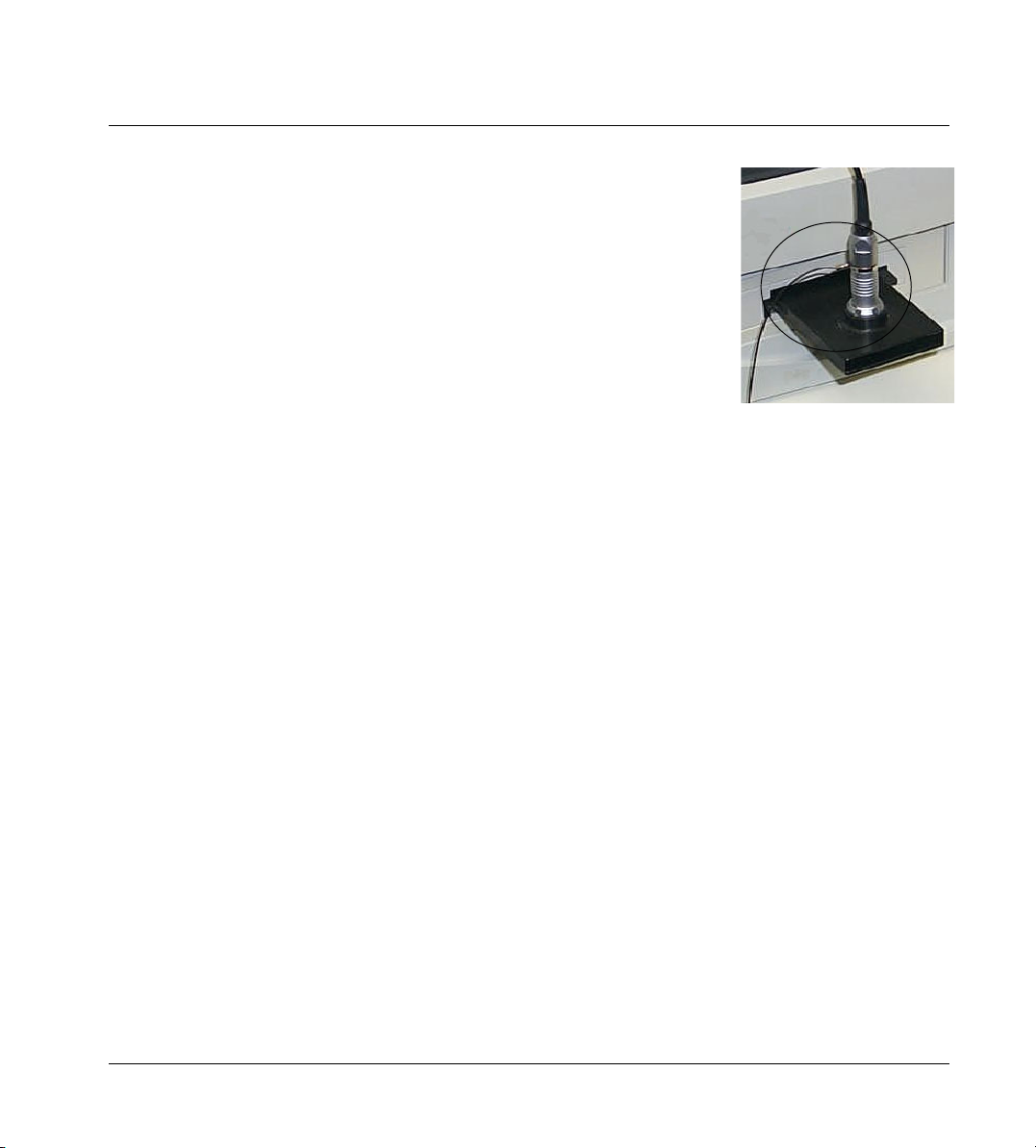
Selecting an Initial Setting
You need to take a few test X-rays with the calculated setting and critically review the images. Connect the sensor to the computer. Place your sensor into
the aluminum testblock and place it on a flat surface with the testblock facing
up. Aim your X-ray tube so that the long axis of the tube is perpendicular to the
flat surface of the testblock. The X-ray head should be directly over the testblock, not more than 1/2 inch away from it.
Choose or create a test patient and open this patient’s DEXray intra-oral
screen. Type “X” on your keyboard to open the Intra-oral X-ray Acquisition
screen. Select a tooth from the chart. Yellow, then green bands will appear on
the tooth chart. Leave the room and trigger the tube.
The DEXray software shows you the enlarged X-ray of the testblock. It looks
rather dull, but since the testblock has a similar radiographic density as an average adult molar, the characteristics of the image will indicate whether the exposure is appropriate for X-raying teeth. Two tools help you in evaluating the
test image:
Color indicator: The appearance of color indictors in the form of dots offers exposure information at a glance. If you receive a yellow dot, your level of radiation is too low. If you receive a red dot, your level of radiation is much too low.
If the dot is blue, the level or radiation is too high. If the dot is black, the level
of radiation is much too high.
19
Page 20
Chapter 2 Installation, Care, and Maintenance
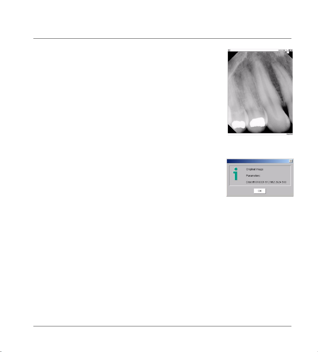
Parameters: Each image has a group of numbers associated with its exposure.
Check the parameters of the enlarged testblock image on the screen by clicking in the space between the date and the tack or on the color dot, if present.
This opens the Image Parameters information box. The second number from
the end (disregarding numbers in parentheses) is the one to look at. If that
number is under 1500, raise the duration setting (seconds or pulses) and test
again. If the parameter is over 2500, lower the duration setting and take another test X-ray. If the number is between 1500-2000, note the exposure setting for
taking X-rays on anteriors. If between 2000-2500, note the exposure setting for
taking X-rays on posteriors..
Note: Since the afore-mentioned parameter is a measure on how much radiation reaches the sensor, its value depends on the radiation issued by the tube,
on the distance between the tube and the sensor, and on the object being Xrayed. The above given numbers are only valid for X-raying the DEXIS testblock.
Click on the color dot in the
upper right corner.
When you X-ray actual teeth, you will usually receive a higher parameter value
because part of the X-ray shows "empty" space around and between the teeth
that is not absorbing much radiation. As a rule of thumb, the parameter value
(second last number disregarding numbers in brackets) is between 2500 and
3000 on well-exposed intraoral X-rays.
Evaluating Images
Use the setting established with the testblock to capture your first images on
patients.
Initially, upon taking images on actual patients, please take the time to critically evaluate the image quality. If images appear grainy, increase the radiation by increasing the time. If they seem rather dark, you should reduce
radiation. There is a wide range in which DEXIS compensates for under- and
over-exposure. If you get good results with a particular setting, you might try
less radiation to see whether you still gain good results.
Remember, as with standard film, you will need to adjust the duration setting
to compensate for tooth type (central incisor to molar) and body type (larger
adult to small child)
The settings you ultimately choose, no matter the setting number or parameter it gives, should be what you consider to be suitable for your diagnostic
needs.
20
Page 21

Chapter 2 Installation, Care, and Maintenance
2.6 Safety Procedures with X-Rays
The rules of dental radiography still apply to digital X-ray systems. Although
there is less radiation with digital X-rays, please continue to use protection for
your patients. As a clinician, clear the immediate area when exposing the sensor.
When beginning to take DEXray images, please use the guidelines in “Taking
X-Ray Images” on page 48. Only take X-rays on patients once you have adjusted your X-ray exposure and taken test images.
2.7 Proper Care of the DEXIS Hardware
The sensor, cable (or cord) and board comprise the heart of the DEXIS system.
Please treat your sensor and board with the care and respect afforded to other
very sensitive electronic devices, such as digital cameras or laptop computers.
The system is extremely important to your practice and productivity; it replaces
your film, processor and darkroom. Please adhere to these important guidelines to keep your DEXIS system running at optimum levels.
2.7.1 Sensor and Board Care
• Never soak the sensor in any solution. Soaking and using caustic chemicals
will weaken the sensor housing and the sensor-cable connection. Never expose the board to moisture. Also, Never autoclave the sensor or board.
• Never use hemostats or "clamping" devices on the sensor or cable. Doing so
will cause sensor housing or cable wiring damage.
• Never twist, tightly coil, or wrap the sensor cable around any objects. This includes coiling it around the sensor board when not in use. Also, keep the
sensor cable off the floor where chairs or carts may roll over the cable. In addition, keep the sensor cable clear of drawers and doors where it may be
crimped upon their closing. Lastly, never pull or stretch the cable including
when disconnecting the sensor from the board or removing barriers. Exposing the sensor cable to these situations will damage the sensor cable causing the sensor to pre-fire, give an unclear image or render it fatally damaged.
• Never allow patients to bite the sensor or cable. This will damage the housing and/or cable and lead to a sensor malfunction. We strongly recommend
21
Page 22

Chapter 2 Installation, Care, and Maintenance
the use the DEXIS holders as they are designed to protect the sensor; In addition, latex barriers, may give added protection. Should you choose to NOT
use a DEXIS holder, you must protect the cord.
• Never insert foreign objects into the board or sensor connection housing.
Doing so will cause a short in the sensor pins and will loosen, and/or damage the connection site.
• Never drop your sensor or board. Dropping the sensor, especially on hard
surfaces such as floors and countertops, will shock the system causing the
internal electronics to malfunction or be fatally damaged.
• Remove the sensor's board from the computer when re-starting the computer, whether during the day or overnight. If the computer is started with the
board in the in PCMCIA slot, it is subject to power fluctuations that may
cause circuitry issues. In addition, always remove the board from the computer before attaching or detaching the sensor.
• Protect the sensor and board. When the sensor/board are not in use, contain
it in a way that will keep it from any conditions that can cause damage.
Please be advised: DEXprotect does not cover abuse or misuse. All visible
damage voids your DEXprotect coverage and warranty.
2.7.2 Connecting your Sensor and Board to the computer
The sensor is connected to the PC Card by a metal connector. This is a precise
connection. Therefore, please take the time to learn how this component functions. To separate the sensor from the board, pull them straight apart without
twisting or turning either part. Once the two are separated, you may cover the
sensor’s connection end with the attached cap.
To connect your sensor to the board, align the red dots on the two parts. Snap
the parts together firmly until you hear a click.
Carefully insert the sensor/board assembly into the PCMCIA slot of your computer. Please use caution, as there may be 2 slots – keep it level and insert into
one slot or the other. In most cases, you will hear two beeps. This is the signal
that your computer recognizes the board. Additionally, you may hear two
beeps each time you remove the board.
22
Page 23

Chapter 2 Installation, Care, and Maintenance
Please note: The DEXIS PC Card (or board) is “hot-swappable” meaning that
you do not have to notify Windows that you plan to remove it. Nor do you need
to restart your computer upon inserting the card. Should you receive a message that you “may lose valuable data” by removing hardware with out notifying Windows, please disregard. This does not pertain to the DEXIS card. The
only time you should not remove the card is when the “Intra-oral X-Ray Capture” screen is open.
2.8 Regular Backups of Image Files
It is extremely important to back up your data on a regular basis as a matter of
routine maintenance. DEXIS offers DEXsafe, a one step feature to copy all or
part of your DEXIS data to a specific backup drive. Please see our hardware requirements for recommendations on devices. Instructions for using DEXsafe
are found in“Backing Up Your Image Files” on page 131.
23
Page 24

Chapter 3 Clinical Use of the DEXIS Sensor Holders
Chapter 3
Clinical Use of the DEXIS Sensor Holders
Please become acquainted with your sensor. The DEXIS sensor has a unique
design; it has clipped corners and is thicker than film. This design, along with
proper placement, translates into patient comfort. The electronics are in the
bubble on the back, thereby utilizing nearly the entire surface of the sensor for
capture. You receive an image approximately equivalent to #2 size standard
film.
If you have not done so, please take some time to review the proper handling
guidelines in “Proper Care of the DEXIS Hardware” on page 21 before attempting to use your DEXIS sensor.
3.1 Overview of the Position-It System
The holders contained in your Position-It kit consist of:
• 2 posterior biteblocks
• 2 anterior biteblocks
• 2 periapical rings and bars
• 2 vertical bitewing biteblocks
• 2 horizontal bitewing biteblocks
• 1 bitewing bar and ring
• 2 vertical endo holders
• 2 horizontal endo holders
•2 cable clips
The bars, biteblocks and rings are similar to the RINN or XCP system and function in the same manner. The bitewing holders may be used with or without the
bars and rings, or you may use bitewing tabs (along with cord protection). The
periapical holders may be used alone or with the rings and bars. When the pe-
24
Page 25

Chapter 3 Clinical Use of the DEXIS Sensor Holders
riapical holders are used without the rings, they function as “stab” device. The
hand-held endo holders may be used with or without the bitewing ring and bar.
The sensor will only fit into the holder one way. Assemble the rings, bars and
holders so that the entire sensor area is visible through the ring. This applies
to horizontal or vertical bitewing holders, periapical (anterior or posterior)
holders, and endo holders.
Place the cord into the groove on the holder. This protects it when the patient
closes. Should you choose to use the cable clip, place the square hole on the
end of the bar and place the sensor cable into the clip.
3.2 Correct Placement Using the Paralleling Technique
We recommend the use of the DEXIS Sensor Holders contained in the “Position-It System” included with your new DEXIS Digital X-ray System. Correct
placement of the DEXIS sensor in the patient’s mouth is essential for obtaining
acceptable X-ray image quality. These holders have been specially designed to
work with the DEXIS Sensor and the DEXray software.
Please note: Holders shipped after January 1, 2003 are autoclavable, provided
you use care and avoid direct contact with metal heating elements. These elements get very hot and direct contact will reduce the lifetime of your holders.
Holders shipped prior to this date may be autoclaved but are more sensitive to
overheating. Avoid direct contact with heating elements and do not expose to
temperatures above 257° F/125° C.
The DEXIS sensor in combination with the supplied rings and holders (PositionIt Kit) use the paralleling technique originally developed by the Rinn™ Corporation. This technique places the sensor in the mouth so that it is parallel to the
long axis of the tooth and perpendicular to the interproximal spaces. By drawing an imaginary line through the occlusal/incisal surfaces (occlusal line) of
the teeth to be X-rayed, and placing the sensor parallel to this line, it will be
perpendicular to the interproximal spaces. To achieve parallel positioning, the
sensor/holder must be positioned away from the lingual/palatal surface and
located in the deeper areas of the mouth in all areas except for mandibular molars.
25
Page 26
Chapter 3 Clinical Use of the DEXIS Sensor Holders
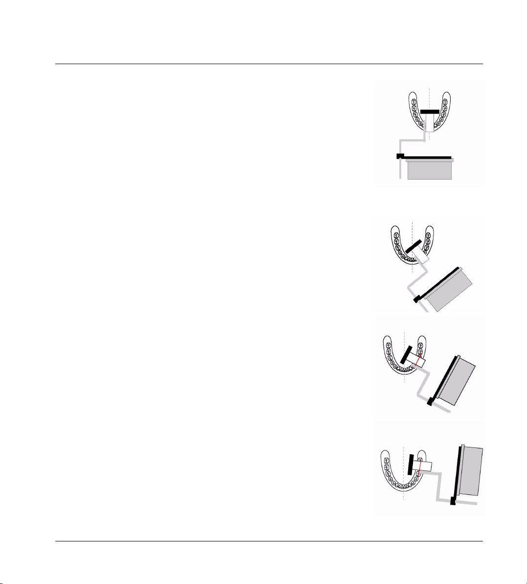
Mandibular Incisor
Position .the sensor/holder so that it is parallel to the roots of the mandibular
incisors. Place either under the tongue or over the tongue, whichever is most
comfortable for the patient. If large mandibular tori are present, position the
sensor/holder behind the tori, even if it is in the first molar area. Ask the patient to close end-to-end in order to maintain the placement. In the event that
the holder does not remain parallel to the roots of the incisors, bisect your angle. Should the incisal edges routinely be missing from your images, place a
cotton roll or flap between the tooth and the holder and/or verify that the sensor holder is parallel to the roots.
Mandibular Canine or Cuspid
Position.the sensor/holder so that it is parallel to the roots of the mandibular
canine. Place either under or over the tongue, whichever is most comfortable
for the patient. If large mandibular tori are present, position the sensor/holder
posterior to the tori, even if it is in the first molar area. Ask the patient to close
end-to-end in order to maintain the placement. In the event that the holder
does not remain parallel to the roots of the canine, bisect your angle. Should
the incisal edges be routinely missing from you images, place a cotton roll or
flap between the tooth and the holder and/or verify that the sensor holder is
parallel to the roots
Mandibular Premolar or Bicuspid
Position the sensor/holder so that it is parallel to the roots of the mandibular
premolars. Place either under or over the tongue, whichever is most comfortable for the patient. Once you establish that the sensor/holder is parallel to the
roots and parallel to the occlusal line, move the sensor/holder to the midline.
Ask the patient to close. In the event that the holder does not remain parallel
to the roots of the premolars, bisect your angle.
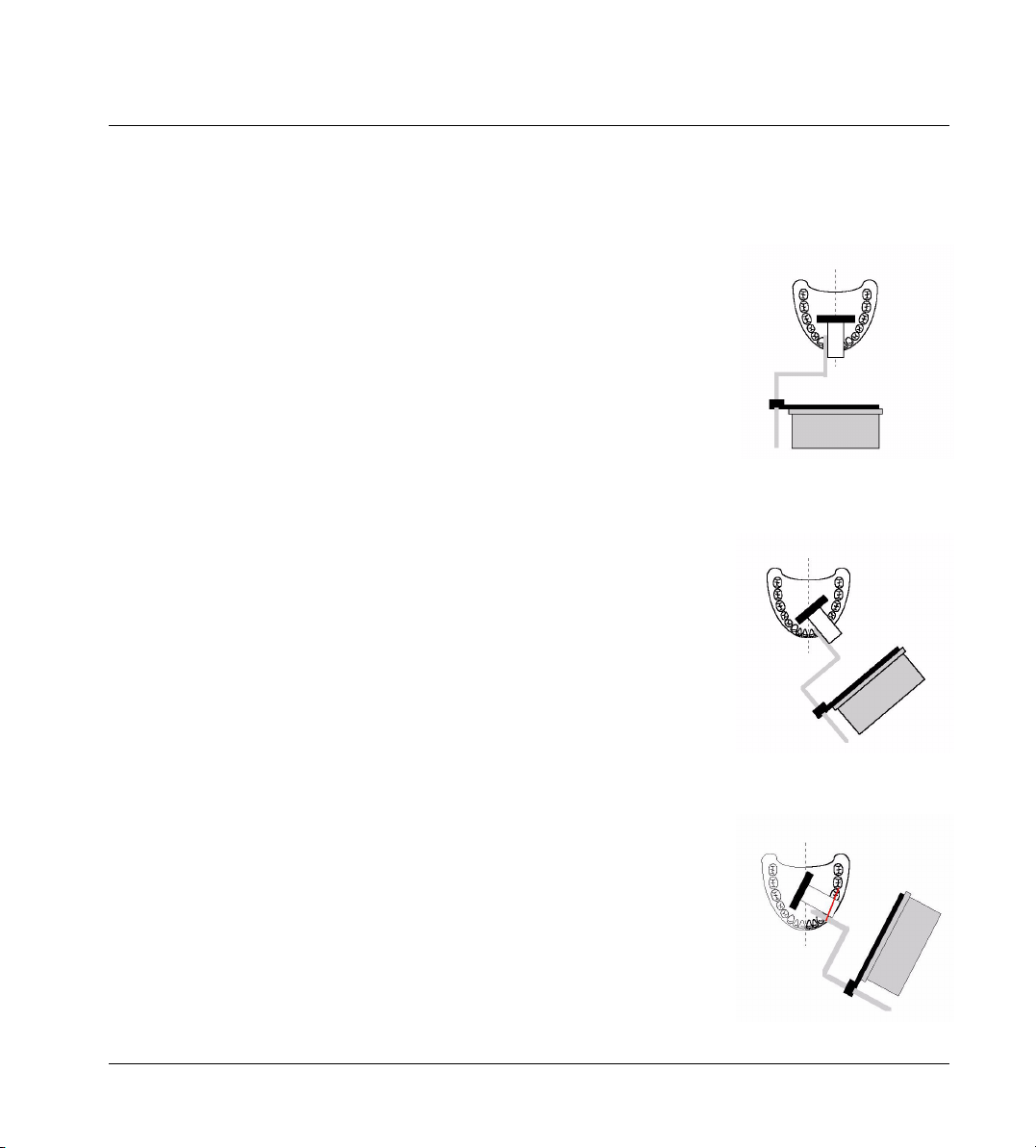
Mandibular Molar
Position the sensor/holder so that it is parallel to the roots of the mandibular
molars. Place between the tongue and the teeth. Once you establish that the
sensor/holder is parallel to the roots and parallel to the occlusal line, ask the
patient to close. This is the only position that does not require placement in the
26
Page 27
Chapter 3 Clinical Use of the DEXIS Sensor Holders
midline for comfort. In the event that the holder does not remain parallel to the
roots of the premolars, bisect your angle.
Maxillary Incisor
Position the sensor/holder so that it is parallel to the roots of the maxillary incisors. Once you establish that the sensor/holder is parallel to the roots, move
the sensor/holder toward the center of the palate. Ask the patient to close endto-end in order to maintain the placement. In the event that the holder does not
remain parallel to the roots, bisect your angle. If a large maxillary torus is
present and you are unable to place the sensor/holder in a traditional position,
the sensor/holder must be placed on the torus as you would place traditional
film and you must bisect you angle. Should the incisal edges be routinely missing from you images, place a cotton roll or flap between the tooth and the holder and/or verify that the sensor holder is parallel to the roots.
Maxillary Canine or Cuspid
Position the sensor/holder so that it is parallel to the roots of the maxillary canine. Once you establish that the sensor/holder is parallel to the roots, move
the sensor/holder toward the center of the palate. Ask the patient to close endto-end in order to maintain the placement. In the event that the holder does not
remain parallel to the roots, bisect your angle. If a large maxillary torus is
present and you are unable to place the sensor/holder in a traditional position,
the sensor/holder must be placed on the torus as you would place traditional
film and you must bisect you angle. If the incisal edges are routinely missing
from you images, place a cotton roll or flap between the tooth and the holder
and/or verify that the sensor holder is parallel to the roots.
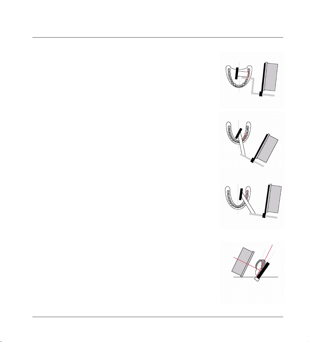
Maxillary Premolar or Bicuspid
Position the sensor/holder so that it is parallel to the roots of the maxillary premolars. Once you establish that the sensor/holder is parallel to the roots and
parallel to the occlusal line, move the sensor/holder toward the center of the
palate. Ask the patient close. In the event that the holder does not remain parallel to the roots, bisect your angle. If a large maxillary torus is present and you
are unable to place the sensor/holder in a traditional position, the sensor/
holder must be placed on the torus as you would place traditional film and you
must bisect you angle.
27
Page 28
Chapter 3 Clinical Use of the DEXIS Sensor Holders
Maxillary Molar
Position the sensor/holder so that it is parallel to the roots of the maxillary molars. Once you establish that the sensor/holder is parallel to the roots and parallel to the occlusal line, move the sensor/holder toward the center of the
palate. Ask the patient to close. In the event that the holder does not remain
parallel to the roots, bisect your angle. If a large maxillary torus is present and
you are unable to place the sensor/holder in a traditional position, the sensor/
holder must be placed on the torus as you would place traditional film and you
must bisect you angle.
Bitewing - Premolar or Bicuspid
Position the sensor/holder so that it is parallel to the occlusal line, move the
sensor/holder toward the midline. Ask the patient to close.
Bitewing – Molar
Position the sensor/holder so that it is parallel to the occlusal line, move the
sensor/holder toward the midline. Ask the patient to close.
Endo Holders
You may use the bitewing bar and ring with the endo holder to use the paralleling technique. Position the sensor/holder so that it is parallel to the root of the
tooth and toward the midline. Ask the patient to grasp the handle after you
have placed the sensor in the appropriate position. The patient may close to
stabilize if position permits. The patient will not be able to close completely
due to the design of the holder. Should you choose not to use the paralleling
technique, bisect your angle.
28
Page 29
Chapter 3 Clinical Use of the DEXIS Sensor Holders
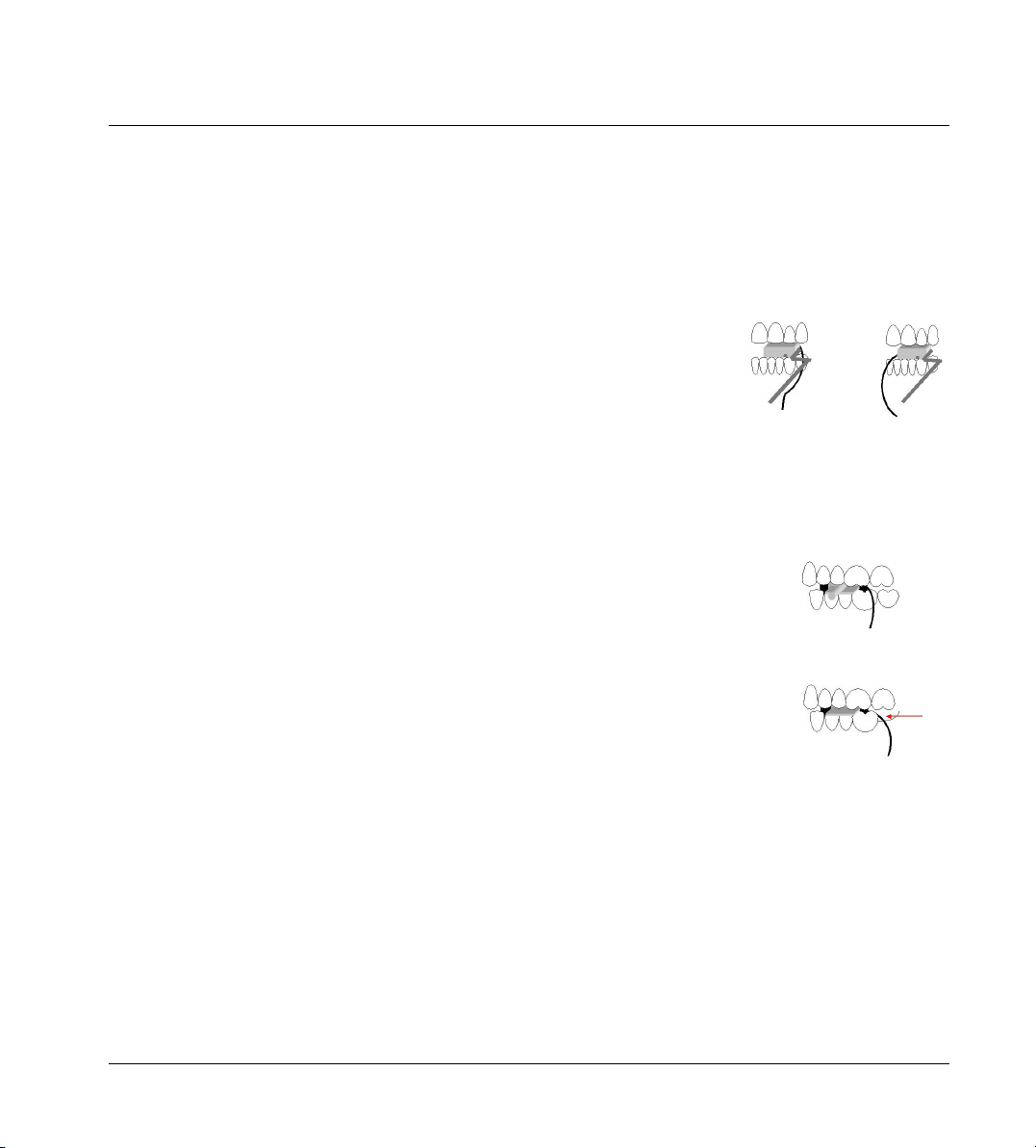
3.3 Cord Protection
There is a groove on the underside of the periapical biteblocks and a slightly
different groove in the bitewing biteblocks. Place the sensor cord into this
groove for protection. This works well when the sensor is placed into the holder
and then the entire assembly is sleeved.
On those occasions where it is necessary to sleeve the sensor before placing
in the holder, due to the thickness of the barrier, the cord may not stay in the
groove. In this case, verify that the cord is adjacent to the holder, either to the
side that is to the anterior or posterior of the biteblock. Since the biteblock will
not allow for full closure, the cord is protected. Again, please verify that the
cord is not between the biteblock and the teeth as it may become crimped
upon the patient closing.
We strongly recommend the use of the DEXIS holders as they are designed to
protect the sensor and cord. However, should you choose not to use the DEXIS
holders, you must take steps to protect the sensor and the cord. The use of latex barriers and sponge bw tabs may offer additional protection. However, no
matter the barrier or bw tab, you must protect the cord
You must always ask patients to close "lightly" so that they have only the
slightest of contact. Do not allow patients to depress the cord. If you feel that
you will not have the patient's full cooperation, place an object such as a folded gauze or cotton roll on the tab, to hold the teeth open just enough to keep
the cord from harm. You may also place the cord in an area where there are
missing teeth or in an area where, anatomically, there is an open space or lack
full occlusion.
3.4 Barriers and Protection
There are many types of barriers that you can use with your sensor, and other
hardware. Sensors must be covered with some type of barrier that covers the
sensor and at least 3”– 4” of the cable. Barriers made of latex, urethane or
plastic (such as a handpiece sleeve) are widely available. Keyboards may be
covered with pre-formed plastic covers or plastic wrap. Use a baggie or a lowtack light handle sheet to cover the mouse. Low-tack light handle covers also
work well for barriers for laptop touch pads. Use sterile barriers for surgical settings.
29
Page 30

Chapter 3 Clinical Use of the DEXIS Sensor Holders
Cleaning and Decontamination of the Sensor and Holders
To comply with ADA and CDC guidelines on decontamination, you must follow
these steps: First, sleeve your sensor with an appropriate barrier, place into
the holder and change the holders as needed. When you complete your images, remove and discard the barrier. Use a hard-surface disinfectant spray or
pop-up wipe on the sensor and cord. Always use a solution that does NOT contain bleach, glutaraldehyde, alcohol, or other strong chemical components.
Your sensor may be washed with warm water and soap, if necessary.
Sterilize/Decontaminate your holders. Please note: The current DEXIS sensor
holders are autoclavable, however, certain restrictions apply:
• Always avoid direct contact of the holders with metal trays, instruments, and
heating elements.
• Always place holders in autoclave bags
• Always situate bagged holders into the autoclave so that they are furthest
from the heat source.
Exposing the holders to hot metal and placing them close to heating elements
will reduce the lifetime of the holders.
Older versions of the holders are more sensitive to overheating. Decontaminate these holders using a cold sterile solution. Please consult the manufacturer's recommendations for the solution you are using.
Should you use only one holder for a patient’s procedure, you may cover the
entire assembly with a barrier. However, decontamination is as previously described: Use hard surface disinfectant on the sensor and decontaminate/sterilize your holders.
Please decontaminate you new sensor and holders prior to use.
Please note: Should you have any questions regarding the decontamination
of your sensor and holders, contact our Customer Care Center.
30
Page 31

Chapter 4 The DEXIS Administration Program
Chapter 4
The DEXIS Administration Program
The DEXIS Administration Program is the starting point for all “stand-alone”
versions of the DEXIS Digital X-ray System. All of the other DEXIS programs (including DEXray, DEXimage, and DEXwrite) are accessed through this program
after first selecting a patient or creating a new patient.
In addition, this program is the starting point for setting up various global
“preferences” or default settings with regard to your office and clinical team
members (“Providers”). Other preferences control the look and feel of the DEXIS program and automate certain frequently used functions.
DEXIS owners who choose to set up their DEXIS programs to interface directly
with their practice management software programs will use the DEXIS Administration Program much less frequently (primarily to set global preferences) as
they will select their patients from the equivalent screen in the Practice Management Software.
4.1 DEXIS Administration Screen Overview
To open the DEXIS Administration screen, double-click on the DEXIS icon on
your desktop.
You may apply certain Windows functions to this screen. You may size the
screen using click-and-drag. You may also use the three buttons in the upper
right to minimize the screen (thus sending it to the task bar — click the tab to
bring it back up), maximize or restore a screen, or close a screen.
There are icons across the top of the screen for various functions. When entered, a list of patients will appear on the right side of the DEXIS Administration
screen. A patient search field, alphabet keys, buttons to access patient information, and Referring Dentists are on the left side of the screen. If entered, patient pictures are visible in this area.
Place your cursor over any of the icons and buttons and a help bubble, called
a Tooltip, will appear with information about the function. Often, there is also
31
Page 32

Chapter 4 The DEXIS Administration Program
a keystroke that will execute the function. The Tooltip help feature is available
throughout the DEXIS system.
There are four program icons that appear on the upper left area of the DEXIS Administration screen: The first leads to the DEXray X-ray screen, the second to
the DEXimage screen, the third leads to DEXwrite, and the fourth closes DEXIS
Administration. (You will only see those icons for which you have installed the
programs.)
Click on the DEXIS logo icon on the far right to open the Program Information
screen. This screen offers program information and will allow you to access the
Context Sensitive Help feature and the DEXIS Web Site.
The Help feature:
Click on the Help button and your cursor gains a “?” symbol. Now, click on a
feature or icon and the DEXIS on-screen manual will open in an Acrobat Reader
screen to the page where the use of the function is described. You may zoom
in on the screen shots to see more detail.
Click on “DEXIS Web Site” to open the site in your browser if you are online.
Click “OK” to close the Program Information screen.
4.2 Entering Practice Details
The “wrench” icon opens Tools and Preferences where a variety of information
is offered and/or changed:
Providers
Click the Providers arrow to open the Provider Selection screen and view the
list of providers for the practice. A search field is located at the top of the
screen. To use the search function, type the first few letters of the provider’s
name until the name appears.
To add a new provider, click New to open a blank Provider Data screen. Type
the last name; DEXIS will capitalize the first letter. Use the tab or arrow key to
go to the next line and add a first name. Again, DEXIS will capitalize the first letter. Add any other information as desired, including the provider’s practice
management number or letters under Ref.#/Initials. Individual provider logos
for use with DEXwrite can be captured with a scanner using the Acquire Logo
32
Page 33

Chapter 4 The DEXIS Administration Program
button. See “DEXscan: Scanned Images” on page 91 for scanning instructions.
Delete the current logo for this provider by clicking the Delete Logo button.
Click “Done” to save or “Cancel” to cancel.
To modify information for an existing provider, search for the name, click on the
name to highlight the line, and then click Modify to open the Provider Data
screen for that particular provider. Alternatively, you may double-click on the
name to open this screen. Tab or arrow down to make changes.
To delete a provider, click on the name to highlight the line, then click “Delete.”
The provider will no longer show on the list; however, patients attached to this
provider will still show the providers name on their Patient Data screens until
another one is selected.
Component Licensing
Click on the Component Licensing button to open the Component Licensing
screen: This area shows your practice name and phone number and is the information with which you license the use of DEXIS. You must obtain a registration code for each of your purchased modules. To obtain a code, go to this
screen and call tech support. Should you decide to change your practice name
or phone number, you will need to re-register within 30 days.
Patient IDs
Should you wish to give your patients specific numbers, choose Manual. DEXIS
will automatically assign a unique number to each patient if you choose Automatic. If you use a practice management software we recommend using manual numbering and entering the ids issued by that software. If your practice
management program is linked to DEXIS, Manual must be selected.
DEXIS defaults to Manual upon installation.
4.3 Setting Global Preferences
DEXray and DEXimage Preferences
Each screen has its own preferences and defaults. You may access the programs’ preferences here or from their actual screens. Please see “Setting
33
Page 34

Chapter 4 The DEXIS Administration Program
DEXray Preferences” on page 43 and “Setting DEXimage Preferences” on
page 79.
Signatures and Logos
These items are used to scan signatures and the practice logo for use with DEXwrite. You may also access these functions from DEXwrite Preferences; see
“Setting DEXwrite Preferences” on page 98. See also “Scanning a Signature or
Logo” on page 95.
Scanner
Once your scanner software is loaded, choose it from the list by clicking on the
arrow button. You may also choose your scanner software in DEXray or DEXwrite Preferences.
Twain Camera
Click on the arrow button to choose the hardware to be used. These choices are
covered in detail in “Taking Digital Photographs” on page 82.
Tooltip delay ms
The number in the box is the delay in time (number of milliseconds) before the
Tooltip bubble appears. Choose between 0 and 9999. By choosing 0, Tooltip
will not appear.
Larger Font
Select the Larger Font box to increase the size of the font on the patient list.
This change takes effect after first closing and then reopening DEXIS. Upon installation, the font defaults to the larger size.
Monitor Testpattern
Monitors are a crucial system component, see “Diagnostic Imaging” on page 9.
By clicking this button you display a testpattern that helps you evaluate the
suitability of your monitor:
• In the squares labeled 0/5% and 95/100%, you should be able to see smaller squares with slightly different brightness inside the larger squares.
34
Page 35

Chapter 4 The DEXIS Administration Program
• You should clearly see gray lines in the squares adjacent to those with black
and white lines.
• If you move the pattern into the corners of your screen, the lines should stay
parallel should be clearly visible.
On 2nd Monitor
This button is for two monitor setups that allow you to move windows between
the two monitors (needs a special display adapter). If the button is checked,
the DEXray and DEXimage screens will be shown on the second monitor, and
the DEXIS Administration screen can be moved to either monitor. The DEXIS Administration will remember its position and will show up on the monitor where
it has been left.
Comm Folder
This is the default folder for importing and exporting images. The DEXIS Setup
sets it to the subfolder Comm of your data folder. You may want to change it if
you frequently exchange images with another program that expects them in a
different location.
Folders
Click on the arrow button to have DEXIS search for possible DEXIS database
folders and to select from the list.
Rebuild Index
If you experience a loss of database information, DEXIS tech support will use
this feature to help you rebuild the database. Please do not use this feature
without assistance.
Print/Export System Info
Should you have technical isues, DEXIS tech support may ask you send information about your computer and the DEXIS installation.
These two buttons issue this information. - It is either printed or written to a text
file on your desktop. The file can be viewed, printed, or sent by e-mail.
35
Page 36

Chapter 4 The DEXIS Administration Program
Specialty
Selecting one of the specialties will initialize preference settings as mostly
used by dentists of the selected specialty. Of course, you may change the individual settings one by one according to your needs, see also “Setting DEXray
Preferences” on page 43.
• General: Set ClearVu Mode to “General” and Startup View to “Mouth”.
• Perio: Set ClearVu Mode to “Perio” and Startup View to “Mouth”.
• Endo: Set ClearVu Mode to “General” and Startup View to “History”.
4.4 Entering Patient Data
The patient list is shown on the main DEXIS Administration screen. You may
use the scroll bar to the right to search for a patient. The search field for patients is located in the top left side of the main screen. Type the first few letters
on the patient’s name until the name is visible. Instead of typing, you may click
on the letter buttons. To select a patient, click on the name; the line then becomes highlighted.
To add a new patient, click the “New Patient” button to open a blank Patient
Data screen. Type a number, if applicable. Tab or arrow down to the next line.
Type the last name; DEXIS will capitalize the first letter. Tab or arrow to the next
line and add a first name. Again, DEXIS will capitalize the first letter. Add any
other information as desired. The Date of Birth may be entered in different formats: with slashes (M/D/YYYY), with dashes (D-M-YYYY), or 6-digit no dashes,
spaces or slashes (MMDDYY).
Choose a provider by clicking on the arrow button next to Provider. This will
bring up the Provider Selection screen. Click on the name to highlight the desired provider, and then click Select.
Choose a referring doctor by clicking on the arrow button next to Referrer. This
will bring up the Referrer Selection screen. Click on the name to highlight the
desired name and then click Select.
Use New Picture to insert a patient’s picture via scanner or digital camera. This
is covered in detail in “Scanning a Picture for Patient Data” on page 95 and
“Taking Digital Photographs” on page 82. Delete the current picture for this pa-
36
Page 37

Chapter 4 The DEXIS Administration Program
tient by clicking the Delete Picture arrow button. Click “Done” to save or “Cancel” to cancel.
To modify information for an existing patient, search for the name and then
click on the name to highlight the line. Click “Modify” to open the Patient Data
screen for that particular patient. Tab or arrow down to make changes.
Modification of the patient number is a special case: you may freely change the
number to one that is not yet given to another patient. You may change the patient number to a number already in use only if the names of both patients are
the same.
To delete a patient file, click on the name to highlight the line and then click
“Delete.” As a security feature, all images must be deleted before the patient
file can be deleted.
Once a patient is added or selected (the line will be highlighted), click the appropriate icon to proceed to his or her DEXray, DEXimage or DEXwrite screen.
Alternatively, you may double-click on the patient’s name to open a screen.
37
Page 38

Chapter 4 The DEXIS Administration Program
However, since DEXIS remembers the last screen opened (DEXray, DEXimage
or DEXwrite) for the last patient, this is the screen that will open for your newly
chosen patient.
Please note: If you are using a DEXIS/practice management link, enter all new
patients through your practice management software and NOT on the DEXIS
Administration screen. See “Interfaces, Bridges, and Links” on page 127 for
more information.
4.5 Administrative Tools
Referring Dentists
Referring dentists need to be entered and matched to patients if DEXwrite is
used to write letters to them. Click on the Referring Dentist button to see the
list of referring dentists. This opens the Referrer Selection screen. A search
field is located at the top of the screen. To use the search function, type the first
few letters on the referrer’s name until the name is visible.
To add a new referring doctor (or a doctor or company to whom you refer or correspond), click New to open a blank Referrer Data screen. Type the last name;
DEXIS will capitalize the first letter. Tab or arrow to the next line and add a first
name. Again, DEXIS will capitalize the first letter. Add any other information as
desired.
Click “Done” to save or “Cancel” to cancel.
To modify information for an existing Referring Dentist, search for the name,
click on the name to highlight the line. Click “Modify” to open the Referrer Data
screen for this particular individual. Alternatively, you may double-click on the
name to open this screen. Tab or arrow down to make changes.
Again, click “Done” to save or “Cancel” to cancel.
To delete a Referring Dentist, click on the name to highlight the line, then click
“Delete.” The referrer will no longer show on the list, however, patients attached to this referrer will still show the name on their Patient Data screens until another one is selected.
Print Reports
The Print Icon allows you to print and export reports containing various data:
38
Page 39

Chapter 4 The DEXIS Administration Program
Print Patient List
This feature prints a list of patients in alphabetical order with patient number,
date of birth, gender, and provider number.
Print Provider List
This feature prints a list of providers showing the provider name, DEXIS number
and practice management number.
Print Ref. Dentists
This feature prints a list of referring dentists showing each doctor’s name, address, phone number and DEXIS number.
Print Activity Report
This feature prints a list of patients and images taken for them over a selected
time period. This list also shows deletions plus initials used for each deletion.
Additionally, it shows the source of each image (i.e., imported, scanned, etc.)
Export Activity Report
You may also choose to export activity information to a file. This file has one
line per activity. The lines contain fields separated by tabulator characters. The
format is suited for import into other software such as spreadsheet programs.
Print Queued Letters
When you chose to put a DEXwrite letter into the queue for later printing (see
“Queue” on page 102), this button will appear on the DEXIS Administration
screen. The function shows a list of all letters in the queue and enables you to
print all letters, to print just selected letters, or to delete letters from the queue.
Import from Communication Folder
If the communication folder (set in Tools & Preferences, see “Comm Folder” on
page 35) contains images, an Import icon will appear in the tool bar. If you click
on that icon, a list with information about each image in the communication
folder will be shown: file name, date, patient name, tooth number.
If you double-click on an image entry, the respective patient file will be selected. If the patient file does not yet exist, the New Patient screen will appear with
39
Page 40

Chapter 4 The DEXIS Administration Program
all known information already entered. When you now open the DEXray or DEXimage screen for this patient, the Import dialog will show up automatically.
This mechanism allows for the easy transfer of images between locations if the
sending dentist A and the receiving dentist B both have a DEXIS system:
1. Dentist A sends X-rays of patient P by e-mail or on a floppy disk to dentist B.
2. Dentist B opens the X-rays with DEXview and selects “Export to DEXIS.” This
will put the X-ray into the communication folder of his DEXIS installation.
3. Dentist B selects patient P either manually by clicking on the Import button
in DEXIS Administration.
4. Dentist B opens the DEXray screen for patient P; the Import dialog shows up
automatically and allows him to import the X-ray.
The mechanism also allows for convenient transfer of images between two
DEXIS databases on the same network. In this case, the Communication Folder
entries of both installations should point to the same folder. X-rays can then
be exported from one database, and semi-automatically imported to the same
patient in the other database.
4.6 Interfacing with Practice Management Systems
Links are available between DEXIS and most Practice Management Programs
(PMP) on the market that contain chairside modules. These links are in most
cases provided by the PMP company based on information from and in cooperation with DEXIS. For some PMPs, DEXIS has programmed links based on information from the PMP company. Please ask your DEXIS representative what
is applicable in your case.
If your PMP does not yet interface with DEXIS, we will be happy to provide the
necessary information. It is usually a minor task to implement the link.
If you have a PMP in your office but plan to implement the link only later, you
should use Manual Numbering in the DEXIS Administration and use the chart
numbers of your PMP as DEXIS patient IDs. This makes a link easier to implement later on.
40
Page 41

Chapter 5 DEXray™: X-Ray Images
Chapter 5
DEXray™: X-Ray Images
The DEXray program is the main software application for acquiring, storing, displaying and sharing Digital X-ray images. It is accessed via the DEXIS Administration program directly from all the major Practice Management Software
programs or from any of the other main DEXIS programs.
DEXray is a sophisticated piece of software that has been carefully designed
and developed to be simple and quick to learn and intuitively easy to use. It is
possible to shoot your first X-ray within minutes of initial setup. All unnecessary keystrokes have been eliminated to ensure that attention is focused on
the patient, not on the computer, while an X-ray image is being taken. Information about the patient, provider, tooth number, date and exposure settings are
automatically captured at the click of the radiation button.
Despite its ease of use, DEXray is enormously powerful in its capabilities. Icons
and function buttons enable the user to move, size, enhance, measure, save,
and compare images with just a click and/or drag of the mouse.
There are many shortcuts and timesaving tools in DEXray, more than appear in
this manual. Typically, there are 2–3 methods for achieving any desired outcome. For users who invest enough time in learning or discovering the shortcuts, tricks, and tools, DEXray will become an invaluable and highly productive
addition to the dental practice.
5.1 DEXray Screen Overview
To open the DEXray screen, select a patient on the DEXIS Administration screen
and click on the DEXray icon. If you use a link to a practice management program, the method for opening the DEXray screen depends on the program in
use.
You may apply certain Windows functions to this screen. You may size the
screen using click-and-drag. You may also use the three buttons in the upper
right to minimize the screen (thus sending it to the task bar – click the tab to
41
Page 42

Chapter 5 DEXray™: X-Ray Images
bring it back up), maximize or restore a screen, or close a screen. For more information on screen sizing and multiple screens, see “Screen and Window Adjustments” on page 125.
The patient information is shown in the header bar; function icons are located
across the top of the main window. Place your cursor on any of the icons and
buttons and a help bubble, called a Tooltip, will appear with information about
the function. Often, there is also a keystroke that will execute the function. The
Tooltip help feature is available throughout the DEXIS system.
The screen is divided into four quadrants. The midline’s teeth numbers appear
in the center of the screen distinguishing the location of each quadrant.
The DEXIS Logo icon gives access to program information, DEXray Preferences,
Help, and DEXIS Web Site, see “DEXIS Logo icon” on page 68.
5.2 Taking Your First Digital X-Ray
Click on your test patient in DEXIS Administration and click on the DEXray icon:
the intra-oral screen of the DEXray program will open. You are now ready to take
your first digital X-ray image!
IMPORTANT: If you have not done so, please take the time to review “Safety
Procedures with X-Rays” on page 21 and “Proper Care of the DEXIS Hardware”
on page 21 before you attempt to use the sensor!
42
Page 43

Chapter 5 DEXray™: X-Ray Images
Attach the sensor to the DEXIS card and insert the card into the PC Card slot. If
this is the first time the card is being inserted in this computer, Windows will
recognize the new hardware and install the drivers. Please wait until this process finishes.
Please do not take your first X-ray on a person!
Instead, put the sensor on a counter or table, flat side up; put a metal object
on top of it – a ring, coin, key or your favorite dental instrument; aim the X-ray
tube over the object, pointing down and about an inch away.
Type “X” on your keyboard to open the Intra-oral X-ray Acquisition screen — it
looks like a tooth chart!
Select a tooth from the chart. Yellow, then green bands will appear on the tooth
chart.
Leave the room, lower the setting by 50%, and trigger the tube.
Your first digital X-ray will appear on the screen after a few seconds!
5.3 Setting DEXray Preferences
You may access the DEXray preferences in two ways:
43
Page 44

Chapter 5 DEXray™: X-Ray Images
From DEXIS Administration, click on the “wrench” icon to open Tools and Preferences; select DEXray Preferences
From a patient’s DEXray screen, click on the DEXIS logo to open the Program Information screen; select Preferences.
Sensor
Select “No Sensor” for workstations where X-rays will NOT be taken, “DEXIS”
for workstations where X-rays are taken, and “Simulation” to have DEXIS simulate taking intra-oral X-ray images. Other choices may be available for additionally purchased modules.
X-Ray Series
When taking a series of X-rays, DEXIS automatically advances from one position to the next once radiation is detected. This method lets you take a series
without having to touch the computer in between.
You can use the sequences already in the system or set up your own sequence,
up to four in total per computer. To see the three sequences already placed into
DEXIS, click on X-ray Series. Please note: For a Full Mouth series, DEXIS uses a
sequence that affords the fewest changes of the holders when utilizing the Position-It kit.
You may edit or overwrite the existing series. However, each group of tooth
numbers, such as seen under Full Mouth “1-3 3-5…”, r efers to a ce rtain position
on the screen. Click on the boxes showing the tooth numbers for each existing
series. Use the arrow keys to move through this box and take note of these
groups of numbers. It is strongly suggested that you use the same groups of
tooth numbers to set up your own series sequence to keep your images from
overlapping on the screen.
To set up your own series, click in a box under Name and give your series a
name. Next, under Teeth, type a beginning tooth number for each image in your
series, then a hyphen, then the ending tooth number, then a space, and so on.
The space lets DEXIS know that you are moving to the next image of your series.
Choose “Done” to save or “Cancel” to cancel.
44
Page 45

Chapter 5 DEXray™: X-Ray Images
Sensor Settings
You may assign a certain color to a specific sensor by first choosing the sensor’s number from the drop down box under Current Sensor, and then clicking
on the desired color in Color Coding. This is helpful if you have multiple sensors in your office: Mark the sensors with different colors and enter the colors
here. The sensor selection buttons on the Intra-oral X-ray Capture screen will
then show the same colors.
You may remove a sensor from the list by choosing the number in Current Sensor and clicking Remove Sensor.
Please call DEXIS tech support before changing numbers in Min. Threshold, Filter Length and Integration Time.
Click Done to save changes and Cancel to cancel.
Format
DEXIS stores the images in one of three image file formats: the proprietary DEXIS format, a compressed format; uncompressed TIFF, helpful if your Practice
Management software is to directly access the images; DICOM, a universal digital format for medical and dental imaging being standard in hospital environments. The default and recommended format is DEXIS. When exporting images
you may still ask for a different format; the DEXIS software will convert the images for you.
Digital Panorama
Shows the brand of connected digital panorama equipment; otherwise blank.
Scanner
Shows blank if no scanner is selected; your scanner software if a scanner is
connected. By clicking the down arrow you can select which of the installed
scanner drivers to use.
Frame Removal
This feature controls how scanned X-rays are to be handled: set to 0 for normal
flat bed scanners to enable automatic cropping of intra-oral X-rays; set to 1 for
single-film scanners – automatic cropping is then disabled; set to some value
between 2 and 7, if the single-film scanner produces black edges or frames.
45
Page 46

Chapter 5 DEXray™: X-Ray Images
Start with 2, and increase the value if the frame is not reliably removed. You
need to select the scanner before setting this value.
Large Image Size, Panorama Size
You can set the sizes of enlarged intra-oral and panorama X-rays in percent of
the screen width. The defaults are 60 for intra-oral, 110 for panorama X-rays.
Address Text, Report Text
Place the practice address in Address Text, up to 5 lines. Choose “Done” to
save or “Cancel” to cancel changes. This information appears on your printouts.
Report Text offers a basic letter. Change the letter here for the default – it can
be adapted for each printout. The referrer (w/o address), patient, date and provider will merge – no other information is available for merging. The letters created from DEXray, unlike DEXwrite, are not saved and therefore not editable.
Background Color
Click on the down arrow to choose a background color for the main window.
Startup View
Choose the Startup View, to select the view you initially want to be visible when
DEXray opens for a new patient. Mouth refers to intra-oral images in the mounted view; History refers to intra-oral images in chronological order; Pano refers
to panoramic or cephalometric images. You will have the option to change
views according to patient, see “Archive icon” on page 61.
ClearVu Mode
Select which mode of the ClearVu image enhancement you prefer. “General
Dentistry” is best suited for detecting caries and fractures while “Perio” shows
bone structures and ligatures in the crispest way.
Record Measurement
Select the results of which type of measurements you want to record as image
notes: all types of measurements, canal measurements only, or no measurements at all. Whenever you carry out one of the selected measurements, you
46
Page 47

Chapter 5 DEXray™: X-Ray Images
will be asked whether to transfer the result to notes, see “Measurement icon”
on page 63.
Auto-Contrast
Check the selection box to have all X-rays appear in contrast mode when initially shown.
Navigator
Check the selection box to show the Navigator when an X-ray is enlarged.
Show Folders
Click to display DEXIS software and data folders.
Initials
You may place initials into this field, which are then proposed when deleting
X-rays. This is useful if the system is always being used by the same person.
She/he then need not put in the initials each time she/he deletes an X-ray.
Tooltip Delay
The number in the box is the delay in time (number of milliseconds) before the
Tooltip bubble appears. Choose between 0 and 9999. By choosing 0, Tooltip
will not appear.
Length of RC File
Set the proposed length of the file to be displayed in Canal Measurement.
Flipped View
Choose Flipped View to have the patient’s X-rays shown in inside-out view, so
that the right images appear on the right side of the screen.
5 Anterior FMS
Choose 5 Anterior FMS to have the screen accommodate 5 anterior images instead of 3.
47
Page 48

Chapter 5 DEXray™: X-Ray Images
Once you added to or changed items in DEXray Preferences, choose “Done” to
save changes, “Cancel” to cancel changes.
5.4 Taking X-Ray Images
Click on the X-ray capture icon or hit “X” on your keyboard. This will open the
Intra-oral X-ray screen. If applicable, choose the appropriate sensor from the
numbers on the lower left area of this screen. Although you will be able to use
“Other Sensor,” choosing the appropriate sensor will result in an image of better quality.
5.4.1 Taking an individual image
Click on the desired tooth or range of teeth on the chart, or type the tooth number and hit the Enter key. The tooth will be highlighted in gold and green bands
will appear (think of this as “green means go”). Also, a message will display,
“Trigger the X-ray tube... ” You have up to 10 minutes to take your image. After
10 minutes, you will receive a “timed-out” message. If this happens, you need
to bring up the Intra-oral X-ray screen again as described above to restart the
process. When you reenter this screen, DEXray remembers the tooth number
last chosen. Click Start or hit the Enter key to receive your green bands.
Now, position the sensor in the patient’s mouth, position the cone close to the
face and expose the sensor as you would with film (but of course using less radiation). Once radiation is detected, the sensor will capture the X-ray and the
enlarged image will appear on the screen.
5.4.2 Repeating an X-ray
If you want to take an X-ray of a tooth (or range of teeth) for which you already
have an X-ray, enlarge the existing X-ray then click on “Repeat X-ray” in the
Navigator box or hit “y” on your keyboard. This will open the Intra-oral X-ray
screen with the tooth selected and automatically prepared to take another Xray.
48
Page 49

Chapter 5 DEXray™: X-Ray Images
5.4.3 Taking a series of images
From the Intra-oral X-ray screen, choose the desired series. The first range of
teeth programmed into the series will be highlighted. Now, position the sensor
in the patient’s mouth to X-ray the highlighted teeth and expose the sensor.
Once radiation is detected, a thumbnail (preview) of the image will appear on
the Intra-oral X-ray screen. DEXray will highlight the next image area and will
show green; your computer is ready to receive the next X-ray of the series. Note:
It is not uncommon for the thumbnail to appear upside down. Remember, it is
only a preview.
If you are not satisfied with your image you can use the Back button on the lower right of the screen to retake the image. If you want to skip forward to a different image area, use the Next button. Please note: You will not need to return to
the computer for the duration of the series unless you want to retake or skip
areas.
When the series is complete, the X-rays will appear as if in a mount. That is,
DEXray will automatically mount your images for you.
For programming your own series, see “X-Ray Series” on page 44
5.4.4 One Tooth Series
Endodontists often have the need to take several X-rays of the same tooth. You
can do that without touching the computer in between by selecting “One Tooth
Series” when taking the first X-ray. If this button is selected the software will
automatically prepare the sensor to take the next X-ray as soon as one has
been taken and is shown on the screen. You cancel out of this loop by clicking
Cancel or by closing the DEXray program.
Note: Since the sensor is always prepared to take the next X-ray, certain restrictions apply:
• Do not remove the DEXIS Mobile card while in One Tooth Series mode.
• The image enhancement functions are slowed down - use them sparingly.
49
Page 50

Chapter 5 DEXray™: X-Ray Images
5.5 Image Management Tools
You may control all functions in the DEXIS software by mouse-click or keyboard, whatever is more convenient for you. The Tooltip bubbles will give a
short description and keystroke for each item. There is a complete listing of
keystrokes in “Keyboard Use and Shortcuts” on page 120.
5.5.1 Selection and Navigation
All X-ray images have a tooth number, date, and close button in a band at the
top (title bar) of the image. To select a specific image, click on the body of the
image (the actual X-ray part of the image). The title bar turns from gray to white.
To sel ect a dif ferent image, click on that image. You may also navigate between
images with the arrow keys.
You can move the small images by clicking on the title bar (the mouse cursor
will become a hook) and dragging to the desired location. This location will be
remembered and the image will come up in the same spot the next time you
open DEXray. But there is always a “home” position determined by the tooth
number, see “Home Icon” on page 61.
You may also move dialog boxes, such as the Navigator, on the screen using
this function.
If you have images with the same tooth number, the newest image will be
“mounted” on top of the previous image with the image’s title bar visible. Click
on the title bar to bring the previous image forward.
Enlarging an Image
To enlarge the selected image, click once on the body of the image or hit the
Enter key. To reduce the image, double click on the image or click on the “x” in
the upper right corner or hit the Enter key. Once an image is enlarged, you may
click on another image to have it appear enlarged. There is no need to reduce
the first image.
The enlarged image may be moved by clicking on the title bar and dragging to
the desired location. It may be resized by dragging at a side or corner; the aspect ratio will be maintained.
50
Page 51

Chapter 5 DEXray™: X-Ray Images
Image Parameters
A bar appears at the bottom of all enlarged images. In this bar the image’s security status shows in a footnote:
• DEXray by DEXIS: Original DEXIS image, not modified
• Original:Other original, unmodified image
• DEXray by DEXIS — Enhanced: Original DEXIS image, contrast and brightness
are adjusted or a filter is active
• Enhanced: Other original image, contrast and brightness are adjusted or a
filter is active
• Scanned: Image scanned into DEXIS software; alteration of the scanned original cannot be excluded
• Derived: Image has been computed, e.g. by subtracting two images
• Imported: Image coming from non-DEXIS software; alteration cannot be excluded
See also “X-Ray Image Security” on page 75.
More image parameters, which may be helpful for technical support, are displayed if you click on the space between the date and the tack of an enlarged
image.
Changing Brightness and Contrast
To change the brightness and contrast of an enlarged image, click and drag on
the body of the image. Up for lighter, down for darker, left for less contrast and
right for more contrast. You may also use the arrow keys to change contrast and
brightness. The changed setting will be visible until changed again; however,
you may always return an image to its original settings using the Home icon,
see “Home Icon” on page 61.
Changing Tooth Number and Date, Mirroring
You may change the tooth number or numbers of an image by enlarging the image and clicking on the current tooth numbers. The Tooth box (a tooth chart)
appears. Click on the tooth or teeth highlighted in gold. This will deselect the
unwanted numbers. Now, click on the appropriate tooth or teeth. You may also
51
Page 52

Chapter 5 DEXray™: X-Ray Images
choose primary tooth numbers. The new number(s) will appear in a box in the
lower left.
Click “Done” to save.
The image will be repositioned on the screen and show the new numbers in the
upper left.
You cannot change the date of a captured X-ray image. The date showing on
your computer when the image is captured becomes the date encrypted into
the image, see X-Ray Image Security. To change the date of a scanned or imported image, click on the tooth number to bring up the Tooth box. It bears an
additional date field, which can be edited.
If an X-ray has been inadvertantly scanned from the wrong side, or if some external equipment delivered a mirrored image, you may flip it back by clicking
the Mirror button in the Tooth Number box. Images mirrored this way are
marked “Mirrored” to avoid confusion.
Tacking an Image
An enlarged image may be tacked to the screen by clicking on the tack button
located on the right side of the title bar. An image tacked to the screen will remain in position when you enlarge another image or when you switch from intra-oral to extra-oral screen or vice versa. You may move a tacked image as you
would any other image. When you have multiple images tacked or enlarged,
the Home function will arrange them proportionally on the screen without overlapping, see “Home Icon” on page 61.
The Navigator
When an image is enlarged, a dialog box opens to the right of the image. If in
mouth view, this Navigator box shows all images taken on the same date as
thumbnails relative to their position on the DEXray screen. If in history view, it
shows all visible images as thumbnails. You may click on a thumbnail to display the enlarged image.
Check the box to the left of Next after and DEXray will automatically advance
through the images for this date. To turn this slide show feature off, deselect
the box. The slide show feature allows an interval of 3 to 30 seconds between
images, i.e., the amount of time before the next image appears. You may use
the space bar to pause and restart the slide show.
52
Page 53

Chapter 5 DEXray™: X-Ray Images
You may take another X-ray of the area shown on the enlarged image by clicking Repeat X-ray or by hitting “Y” on your keyboard, see “Repeating an X-ray”
on page 48.
If the Add ClearVu button is selected, enlarged images are shown side by side
in two modes: standard mode and ClearVu, see “ClearVu icon” on page 60.
You may choose to clear the screen of all but the selected image by clicking on
Clean or “L” on your keyboard. Click on the button or “L” again to deselect the
function.
You may move among the images using the Prev (for previous) button, or “P”
or Backspace on your keyboard, and the Next button, or “N” or Space on your
keyboard.
Click on the Compare button to compare two images. See “The Compare Function” on page 57 for a full description of this tool.
You may hide the Navigator for an image by clicking Done. Turn off Navigator
entirely in Preferences, see “Navigator” on page 47.
5.5.2 DEXray Screen Icons
An icon will turn gold when initiated. For example, when on the intra-oral
screen the “tooth” icon is highlighted. When a function icon is chosen or an appropriate key is typed on the keyboard, the selected image will automatically
enlarge and the function box will open next to the image. In addition, many
icons will allow you to drag an image to them thereby opening their function.
Click again on the icon or corresponding keystroke to terminate its function.
In addition, DEXIS will apply the current function to another image once you
click on that image. There is no need to close the current function and image to
work on a newly chosen image.
Please remember, the Tooltip is available for help. The corresponding keystroke will show in the help bubble.
DEXimage icon
The Wand icon leads DEXimage to where images from intra-oral, microscopic,
digital cameras or scanned photos are captured, stored and managed. Click on
the icon or type “V” (for video) to initiate its function.
53
Page 54

Chapter 5 DEXray™: X-Ray Images
Intra-oral and Extra-oral icons
By clicking on the Intra-oral or “tooth” icon, you switch to the intra-oral screen.
The Extra-oral or “head” icon leads to this patient’s extra-oral X-ray screen
where digitally captured or scanned panoramic or cephalometric images are
stored and managed. Click on this icon or “O” (for outside) to move to this
screen.
Note: By dragging an image to one of these icons, it will be moved to the ap-
propriate screen.
Zoom icon
Use the Zoom or “Magnifying glass” Icon to magnify an area of an enlarged image. You may also type “Z” (for zoom) or drag an image to this icon to initiate
its function.
Once this function is initiated, notice that a box appears on the standard-sized
image. The contents of this box correspond to the visible part of the magnified
image. You may click and drag the box on the standard-sized image to view a
different area.
On the magnified image, the active function for the different areas is indicated
by the mouse cursor: an arrow in the center which you can click and drag to
change brightness/ contrast, and a magnifying glass at the edges which you
can click to view a different part of the image.
Click on the Zoom icon again or double click on the body of the magnified image to return to standard enlargement.
As an added feature, once you choose the area of magnification you may tack
(see “Tacking an Image” on page 52) the magnified image to the screen and select the same or another image by clicking on it and view it in standard enlargement or magnification.
Notes icon
This icon will allow you to attach text (notes, diagnoses or comments) to an image or to a selected area of the image. You may click on the icon or type “T” (for
text) or drag an image to the icon to initiate the function.
You may change the type or number of an image using the selections at the top
of the box.
54
Page 55

Chapter 5 DEXray™: X-Ray Images
You may type text in the box below “Notes:” or click on the down arrow to open
the Select a Diagnosis or Condition screen that displays categories of conditions and diagnoses from which to choose.
If you have existing text attached to an image you will be asked to choose “Append to Note” in order to add additional text or to eliminate your current note
by choosing “New Diagnosis.”
For each category, you may add, edit or replace the text by typing into the appropriate field. Click on the selection box to the left of the diagnosis or condition to select it.
If you edit or add a new diagnosis or condition, you will be asked if you wish to
permanently save it.
Click “Done” to save your changes to the list of diagnoses and conditions or
“Cancel “to cancel.
Once all selections are made or text is typed, click “Done” to save or “Cancel”
to cancel.
The last line of text appears or the last diagnosis chosen appears on the title
bar of the image as space permits.
To remove a note, open the function; delete the text and click “Done” to save.
To enter Alerts referring to a specific region on the X-ray, open the Notes function and then click on “Alerts”. Again, you may type text here, or pick from the
list as described in the previous section. To place additional Alerts on the same
image, click on the Next button and add your Alert as previously described.
Before clicking “Done” for your final save, click and drag to draw a box around
the area of concern. Now click “Done” to save. A red box now shows on the image.
Your message will appear when the cursor is stopped in the box of an enlarged
image or when you click in the red box of a standard-sized image. The up to 5
lines of the full text will be visible. To remove the text and the box, open the
notes function again then open Alerts. Delete the text and click “Done” to save.
Enhancement icon
Click on the Enhancement icon or type “E” to use different display modes.
55
Page 56

Chapter 5 DEXray™: X-Ray Images
Please note: These modes do not alter the image files; they instead extract dif-
ferent information from the image files and emphasize the display to aid in
your diagnosis. A mode that aids in diagnosis for one condition may not with
another condition. Please inspect the modes thoroughly and experiment with
them; you may always return the image to its original settings using the
“home” icon, see “Home Icon” on page 61
The top of the Enhancement dialog box shows a histogram of the selected image and a curve showing the current contrast and brightness setting. You may
manipulate this curve by clicking and dragging at the two crosses.
Contrast
This mode displays the image in a more contrasted way. This mode was designed to help in cavity detection. The keystroke for this feature is “C.”
Neutral
This feature will restore the image back to its neutral settings. The keystroke for
this feature is “t” (for take back).
Invert.
Invert or the keystroke “I” displays the image in negative mode. Click and drag
in the center of the image or use the arrow keys to change brightness and contrast. Click again to turn off Invert
56
Page 57

Chapter 5 DEXray™: X-Ray Images
ClearVu
This mode clarifies and sharpens the image. Click on ClearVu or “U” on your
keyboard to use the ClearVu function. When “General Dentistry” ClearVu mode
is selected in Preferences (see “Setting DEXray Preferences” on page 43),
ClearVu resets the brightness and contrast to neutral; to change, click and drag
in the center of the image or use the arrow keys. Click again on ClearVu or type
“U” to turn the feature off. This mode is remembered between sessions. This
means that if you leave it turned on, images will always appear in ClearVu
mode until you turn it off.
Darker
This mode compensates for density differences on the image and is highly recommended for bitewing images. Click and drag in the center of the image or
use the arrow keys to change brightness and contrast. Click again on Darker to
turn the feature off. This mode is remembered between sessions. This means
that if you leave it turned on, images will always appear “darkened” until you
go back and turn it off.
Color
This mode colorizes the image. Click and drag in the center of the image or use
the arrow keys to change the colors. Click again on Color to turn the feature off.
Please note: You may combine Invert with ClearVu and Invert with Color.
The Compare Function
Compare allows for the comparison of two images either side-by-side or overlaid in different modes to ascertain their differences. It was designed in response to requests by the research community; however, all DEXIS owners
have the opportunity to use this function.
Select your first image, usually the newer of the two. Click Compare in the Navigator box (see “The Navigator” on page 52) to open the X-ray Comparison box.
The software will show the selected image and an older one of the same tooth
next to each other. The Comparison box gives you the choice to select a different image to compare to by listing all images of the same tooth and “Other”.
When you selected “Other” or there is no image with the same tooth number,
57
Page 58

Chapter 5 DEXray™: X-Ray Images
you will be asked to choose your second image by clicking on it. You can now
select one of the four comparison tools: Show Side-by-Side, Color Addition,
Subtraction, Red-Green Stereo.
Show Side-by-Side
This is the default mode. It shows the two images next to each other and proportional in size.
Choose one of the remaining tools, and the images are overlaid with the selected tool applied.
Aligning Images
Since two images will rarely be captured using the exact same angle or position, it will be necessary to align the two using the following methods – the active function will be shown through the shape of the mouse cursor:
Click and drag in the center of the image to reposition the entire second image
on top of the first.
Stretch the second image horizontally by clicking and dragging on the side or
vertical margins of the image.
Stretch the second image vertically by clicking and dragging on the top or bottom or horizontal margins of the image.
Rotate the second image by clicking and dragging in a corner of the image.
Alternatively, you may use the “+”, ” –“, and “0” buttons in the upper part of
the X-ray Comparison box:
Horizontal Shift: move the second image to the left (-) or right (+).
Vertical Shift: move the second image to down (-) and up (+).
Rotation: rotate the second image counter-clockwise (-) or clockwise (+).
Horizontal Stretch: shrink (-) or stretch (+) the second image horizontally.
Vertical Stretch: shrink (-) or stretch (+) the second image vertically.
Click on the “0” to return the function to the original value.
The Weight tool shifts the appearance of one image over the other.
58
Page 59

Chapter 5 DEXray™: X-Ray Images
Colored Addition
The goal of Colored Addition is to have areas of common density appear gray
and the non-common areas in green or magenta. The color areas are changes
in density from the first X-ray to the next.
Once your images are aligned, use the Weight scale if necessary. By moving the
sliding bar to the left the second image (in green) becomes more visible or has
more “weight.” Move the bar to the right and the first image (in magenta) becomes more visible or has more “weight.” By moving the bar to balance the
weight, gray areas (common densities) appear.
On the combined, aligned image, magenta areas are areas of greater density
on the first image while green areas are areas of greater density on the second
image.
Subtraction
The goal of Subtraction is to have areas of common density appear gray and
the non-common areas in light or dark. The light and dark areas are changes in
density from the first X-ray to the next.
Once your images are aligned, use the Weight scale if necessary. By moving the
sliding bar to the left the second image (in green) becomes more visible or has
more “weight.” Move the bar to the right and the first image (in magenta) becomes more visible or has more “weight.” By moving the bar to balance the
weight, gray areas (common densities) appear. The second image is subtracted from the first one, which means that if you give more weight to the second
one, the resulting image will appear negative.
On the combined, aligned image, lighter areas are areas of greater density on
the first image and darker areas are areas of greater density on the second image.
Stereo
The goal of Stereo is to achieve a 3-D appearance. Choose two images for the
same area that were taken at slightly different angles (8 degrees or less). When
viewed with 3-D glasses (red-green lenses), the combined image appears in 3D. The Weight tool can also be used to enhance the 3-D image.
59
Page 60

Chapter 5 DEXray™: X-Ray Images
Invert Logic
Use Invert Logic to reverse the properties of the compared images; i.e., have
the second image take over the role of the first one and vice versa.
Save
You may save the combined images as an additional image by choosing
“Save”. The new image will have the current date and the parameter “Comparison: (date of first image) vs. (date of second image)” When using “Color Addition” and “Stereo” the saved, combined images will appear on the X-ray screen
and print in color. The security bar will show “Derived”.
ClearVu icon
The ClearVu or “eye” icon is a shortcut to the ClearVu mode. Two modes are
available and can be selected in Preferences: “General Dentistry” and “Perio”,
see “Setting DEXray Preferences” on page 43. As discussed under Enhancements, click on ClearVu or “U” on your keyboard to use the ClearVu function.
This mode clarifies and sharpens the image. Click and drag in the center of the
image or use the arrow keys to change brightness and contrast. Click again on
ClearVu or type “U” to turn the feature off.
Voice Notes icon
To attach a voice note to an image you must have a sound card and microphone attached to your computer.
To start, click on the Voice Notes icon or type “S” for sound. This opens the
“voice recorder.” There are buttons for rewind, record, play, stop and fast-forward.
To record, click on the “Record” button (circle symbol) or type “R” on your keyboard.
After recording the message, click on the “Stop” button (square symbol) or
type “S” on your keyboard. Click “Done” to save.
Musical notes will appear in the upper left corner of the image to the right of
the tooth number(s). Click on these musical notes to play the sound attachment. Alternatively, you can re-open the Voice Notes function and click on the
“Play” button (single forward arrow symbol) or type “P” on your keyboard.
60
Page 61

Chapter 5 DEXray™: X-Ray Images
To stop, click on the “Stop” button (square symbol) or type “S” on your keyboard. In addition, rewind by clicking on the “Rewind” button (double-arrows
to the left) or type “B” on your keyboard; fast-forward by clicking on the “Forward” button (double arrows to the right) or click “F” on your keyboard. To delete the voice note, click on the “Erase” button.
When adding to a previous sound note, you have several options:
Use the “Forward” button to “wind the tape” to the end before recording. This
will append the new recording to the end of the existing recording.
Start recording to insert the newer recording before the existing recording.
Erase the existing recording and begin again.
Rotate icon
Although DEXIS software orients captured X-rays automatically, occasionally
the proper orientation cannot be recognized. In this case the image (standard
and enlarged) may be rotated using the Rotate icon. You can also type “R” on
your keyboard or drag the image to the icon to rotate it in 90-degree increments.
Home Icon
The “Home” function is activated by clicking on the “Home” icon, by typing “B”
(for back) on your keyboard, or by dragging the image to the icon.
There are 3 sub-functions of the “Home” icon:
1. Return the contrast of an enlarged image to standard settings. The function
toggles between neutral setting and contrast setting.
2. Standard images that have been moved from their original position are
placed back by clicking the Home icon when no image is enlarged.
3. Tack one or more images to the screen using the “tack” in the upper right
corner of an enlarged image. Click on the Home icon. The images appear
enlarged and proportionately sized without overlapping.
Archive icon
The “Archive” icon allows access to the patient’s entire image history. Equate
this feature to searching through a patient’s chart to choose which films are to
61
Page 62

Chapter 5 DEXray™: X-Ray Images
be placed on the view box for the current procedure. To “file” an image or to
place it in the Archive, close a standard-sized image using the “x” or drag it to
the icon and a box will open asking you to Archive or Delete. Choose Archive
and the image will be placed in the archive.
Archive Screen overview
Click on the “Archive” icon or type “H” for a “history” of images for the patient
in order to open the Visible Images screen.
Visible Images refers to the images that are currently visible on the screen.
Again, this may be changed for every patient and every procedure.
All images are listed in the center area by tooth numbers and dates. A small selection box is located next to each. This part of the screen is set up in quadrants-UR, UL, LR, LL and bitewing area in the center.
There is also an area that resembles a tooth chart. Teeth in gold with a black
outline have images that are visible on the current X-ray screen. Teeth in gray
with a gold outline have images that are currently archived or hidden so they
are not visible on the current X-ray screen. Teeth in gray with a black outline
have no images.
Choosing Visible Images
You may choose to hide all the images by clicking the “Hide All“ button in the
upper left of the screen or to show all the images by clicking on the “Show All”
button.
You may pick images taken on a certain date by using the drop down arrow next
to Show consultation of and clicking on the desired date. You may pick images
taken since
a certain date by using the drop down arrow next to “Show Images”
since and clicking on the desired date. When the date(s) are chosen, the image
selection buttons for those specific images are checked.
You may click on the image selection box to select and deselect individual images.
In addition, you may click on the actual image on the X-ray screen to select or
deselect the image.
For help in identification, the selected image on the X-ray screen has its box
highlighted in Archive.
62
Page 63

Chapter 5 DEXray™: X-Ray Images
To view your selected images in a mounted format, click on the Mouth button
on the lower left of the screen.
If you want to view your selected images in chronological order, choose the
“History” button. The “History” view is helpful when performing a procedure for
one tooth or area, such as endodontics. Once this view is chosen and you return to the X-ray screen, all captured images will also appear in chronological
order.
After making your selections, click “Done” to see only the requested images in
the requested view.
DEXray allows you to see all images for a certain tooth or area from different
dates. For example, if a patient has pain on tooth #1, open “Archive”, click on
“Hide all” and click “tooth #1” on the tooth chart. Next, choose the desired
view and then “Done”. All images that include tooth #1 will appear on the
screen in the view you selected.
Measurement icon
The Measurement tool is primarily used for endodontic and implant measuring, although any area on an image may be measured, e.g., a periodontal defect or overhanging margin.
General Distance Measuring
To begin, enhance the image to its
optimum contrast. If desired, enlarge the image by resizing. Click
on the Measurement icon or type
“M” on your keyboard. This opens
the measuring function box
Grid
Click on the “Grid” button. This displays a millimeter grid on the image (centimeter grid for panoramic and cephalometric images). This grid, of course, is in
relation to the sensor and does not take into account the foreshortening or
elongation of an image.
63
Page 64

Chapter 5 DEXray™: X-Ray Images
Distance
Click on the selection button to the left of Distance. Click on the image at your
start point. You can continue the measurement by adding additional points as
necessary, DEXIS will add each subsequent distance to the previous one.
These multiple points allow you to follow the shape of anatomical structures.
You may use Delete or Backspace on your keyboard to delete points beginning
with the last one entered. You may also drag points (shown as crosses) and insert new points by clicking and dragging on segments to conform to shapes
once your final measurement is obtained. The total distance is shown in the
function box.
Double-click the “Distance” selection button to start a new measurement.
To measure using your keyboard, move the green circle to a start point using
the arrow keys, then hit Enter to establish a point. Next, move the new green
circle to the next point and hit “Enter”. Continue until you have the desired area
measured.
Endodontic Measurement
Initial Measuring with the Distance Feature
To obtain the initial lengths of the canals before files are set, you need to use
the general distance measurement as described above. Click on the image at
a starting point where the rubber stopper would contact the tooth. Using multiple clicks, follow the shape of this first canal. Make a note of the distance
shown. Next, measure the remaining canals in the same fashion. Since this
measurement is not calibrated, take into account that the canal(s) may be
shown elongated, i.e., the actual canal length might be shorter than the measurement suggests.
64
Page 65

Chapter 5 DEXray™: X-Ray Images
Canal Feature
The Canal Measurement compensates for projection errors by calibrating the
measurement with the known length of the endodontic file. To use this feature,
the image must show the entire tooth and the initial file(s) must be set.
Open Measurement, change the number of canals if applicable and then click
on Canal. Click on the Site boxes to change or give the canal an abbreviated
name that refers to its location.
Adjust the file lengths in all the “Depth” boxes by using the up and down arro ws or b y typin g the nu mber in the box. These distances, from the rubber stoppers (or handles) to the end of the files, are known values. The software will
need to know these lengths in order to calibrate the remaining information to
compensate for possible image elongation or foreshortening.
The default length of 20mm may be changed in DEXIS preferences.
Measuring with the Canal Feature
Starting with the canal whose site box is highlighted in gold, return to your image. The Canal function needs three
clicks: Click on the beginning of the file
where the rubber stopper touches the tooth, then click on the end of the file,
65
Page 66

Chapter 5 DEXray™: X-Ray Images
and then click on the apex
. The software will automatically insert a forth point
to make the line a smooth curve and also to make it follow the shape of the canal. You may drag the points to further adjust them.
Keyboard users may select the Correct button to adjust points. After selecting
Correct, hit Enter and use Backspace to move to the desired point. Then use the
arrow keys to reposition the point. Hit “Enter” to save the changes.
The measurement dialog box shows the distance between your end-of-file
point and the apex- point and the entire length of this canal (the sum of the file
length and the remaining distance). Click “Next” to go to the next canal and repeat the process.
Saving information
Once you finish with all canals, click “Done”. When asked to “Transfer results
to notes?” choose “Yes” and the new lengths will be listed in the Notes and appear on the image in its title bar. This feature can be switched on and off in Preferences.
Calibrated Measurement
The Calibration feature provides a more general method to compensate for projection errors by comparing to a known length. It is most often used by the implant community. To calibrate, there must be an object of known length entirely
visible on the image. Also, the area to be measured must be along the same
axis as this known object. An example of such a known object is the thread of
66
Page 67

Chapter 5 DEXray™: X-Ray Images
an implant or the length of a directional post being placed prior to placing the
actual implant.
Open Measurement and click on “Calibration”. Click on the beginning and end
of the known object. An “Attention” box will open and the approximate length
of the object will be shown. You will be asked to “Please enter true (or your
known) distance” to replace the shown distance. If these distances are the
same, your image is not foreshortened or elongated. If not, enter the true distance and click “Done”.
Now, measure along the same axis using the techniques for Distance; you may
use multiple clicks. The new measurement will compensate for any foreshortening or elongation. It will appear in red on the image and in the measurement
box under Distance in mm.
Bone Density Measurement
The radiographic density of the X-rayed material directly relates to the gray level of the resulting image. If you click on the Density button then drag a rectangle on the image, the median density of the selected area will be shown as
percentage:
• 0% = black = lowest density
• 100% = white = highest density
The values shown relate to the original image and are not modified by modifying brightness or contrast.
67
Page 68

Chapter 5 DEXray™: X-Ray Images
Quit icon
Click on the “X” icon, type “Q” (for quit) on your keyboard, click on the “x” in
the upper right corner of the screen, or hit the “Esc” key to leave the patient’s
DEXray screen.
X-Ray Capture icon
Click on the X-Ray Capture icon or type “X” on your keyboard to open the Intraoral X-Ray Capture screen in preparation for capturing images, see “Taking XRay Images” on page 48.
Scanner icon
Click on the Scanner icon or type “S” on your keyboard to open the scanner
software in preparation for scanning X-rays, see “Scanning X-Ray Films” on
page 91.
DEXwrite icon
Click on the DEXwrite icon or type “W” on your keyboard to open the DEXwrite
program for the selected patient, see “DEXwrite: Chairside Report Generator”
on page 97.
DEXIS Logo icon
Click on the DEXIS Logo icon or click “I” on your keyboard to obtain program
information, the DEXray Preferences button and these two additional features:
Help
Click on this button and your cursor gains a “?” Now, click on an item on the
DEXray screen and the manual will open in Acrobat Reader to the page that describes that item’s function.
DEXIS Web Site
Click on this button to open the DEXIS web site in your browser.
Click “OK” to close the Program Information screen.
68
Page 69

Chapter 5 DEXray™: X-Ray Images
5.5.3 Communications: Printing from DEXray
Before printing from DEXray, please verify that your printer functions outside
DEXIS.
Note: Images should be enhanced prior to printing.
Click on the Print icon, or type “P” on your keyboard to open the Windows Print
Dialog. This dialog allows you to select a different printer and to access the
printer settings. You may also open the Windows Print menu by dragging an image to the Print icon.
Print Dialog Overview
From the Windows Print dialog, choose “OK” to open the DEXIS Print Dialog.
You will notice that this screen is similar to the Archive screen. All visible images are listed in the center section by tooth numbers and dates. A small selection box is located next to each. In addition, this part of the screen is set up in
quadrants-UR, UL, LR, LL and bitewing area in the center.
You may choose images taken on a certain date by using the drop down arrow
next to Print Consultation of, and clicking on the desired date. You may choose
images taken since
certain date by using the drop down arrow next to Print Im-
ages since and clicking on the desired date.
When the date(s) are chosen, the image selection boxes for those specific images are checked.
You may click on the image selection box to select and deselect the images for
print.
In addition, you may click on the actual image on the X-ray screen to select and
deselect the image for print.
For help in identification, the selected image on the X-ray screen has its box
highlighted.
When you are finished selecting the images, choose to print the image with the
notes attached to it and/or print in ClearVu.
Choose a print format
• “Start Printing” for 6 images per page
• “Print Enlarged” for 2 images per page
69
Page 70

Chapter 5 DEXray™: X-Ray Images
• “Full Mouth” to print images in landscape or horizontally on the paper simi-
lar to a full mouth mount
• “Report” to add the images to the standard report. The text of the standard
report can be modified in DEXIS Preferences; the text of an individual report
can be modified before printing. In the report the referring dentist, patient,
date, and provider information will be merged. Arrow down to change the
text as needed; you are changing it for this patient only. Now, choose “Done”
to start printing. Please remember, the letter will not be saved in DEXIS nor
can you change font or layout. Only DEXwrite offers this feature, as well as
other merging and format possibilities.
Once you choose one of these functions, the information will be sent to the
printer.
“Add to Printout” will allow you to print additional images on the last page
printed for this patient. This feature is for standard sized images given only
with the “Start Printing” button. It can be used to add an intra-oral camera image to a previously printed intra-oral X-ray to the same page. After the initial
print, insert the paper, choose your images and choose “Add to Printout”.
5.5.4 Communications: Export
Click on the Export icon or type “>” on your keyboard to open the Export Images
screen. Alternatively, you may drag an image to the Export icon to open the Export Images screen.
Choose a destination:
• “E-mail” to send images electronically
• “Floppy Disk” to copy images to a floppy disk
• “Hard Disk” to copy images within your own system
• “to:” The area to where images will transfer appears in a box on the upper
left marked “to:” You may type a destination folder into this box.
Choose a format
DEXIS to move images within your own DEXIS system or to send to colleagues
with DEXIS or DEXview.
70
Page 71

Chapter 5 DEXray™: X-Ray Images
TIFF (.TIF) or JPEG (.JPG) to export images for use by other software programs.
These formats are generally accepted by word processing and graphics software programs.
DICOM is for colleagues who have DICOM-compliant software. DICOM is a universal digital format for medical and dental images. The image carries patient
information and the date on which the image was taken. Dentists with DICOMcompliant software from different suppliers should be able to exchange X-rays
along with the medical information attached to them.
Choose images
You may choose images taken on a certain date by using the drop down arrow
next to Export Consultation of and then clicking on the desired date. You may
choose images taken since
a certain date by using the drop down arrow next
to Export Images since and then clicking on the desired date. When the date(s)
are chosen, the image selection boxes for those specific images are automatically checked.
You may click on the image selection box to select and deselect the images for
export.
In addition, you may click on the actual image on the X-ray screen to select and
deselect the image for export.
When you drag an image to the Export icon, that image is automatically selected.
For help in identification, the selected image on the X-ray screen has its box
highlighted in Export Images screen.
Send images and/or DEXview:
Export images + DEXview to export images and the DEXview program
Export installable DEXview to export only the DEXview program for installation
on a different computer
Export Images to move images within your system, to send images to colleagues who use DEXIS or to send images to colleagues who have previously
installed DEXview
Click “Cancel” to cancel the export process
71
Page 72

Chapter 5 DEXray™: X-Ray Images
Once you make your selection and the export is accomplished, the Export Images screen will close.
5.5.5 Additional Information
Move Images to the Correct Patient
The Export function may be used to move an image that was taken on the
wrong patient’s screen. By choosing Hard Disk, selecting images and then
choosing Export Images, the images move to the DEXIS communication folder
ready to be imported into the correct patient’s screen, see “Communications:
Import” on page 73.
Please note: these images are not removed from the incorrect file; they are simply copied. The images will need to be deleted from the incorrect file.
Send a Set of X-Rays on Floppy Disk
To send a set of X-rays to a colleague who does not have DEXIS, choose Floppy
Disk and DEXIS format and then select the desired images. Now choose to Export images + DEXview, to send the images with DEXview. Your colleague simply needs to insert the floppy disk and double-click on DEXview to view the
images.
E-mail Images
Choose E-mail and the appropriate format and then select images. Either add
the recipient’s e-mail address to the “to” field behind the “>” sign, or add it later to the message in your e-mail program. Now, choose Export installable DEXview to send only the viewer, or Export Images to send only the images. For
security reasons you may not send images and DEXview together. Once the
screen closes, your e-mail program will open with a new message created with
the X-rays attached. Send the message as you would any other e-mail message.
Place images directly into word processing programs
To copy an image to a word-processing program such as Word or WordPerfect,
enlarge and enhance the desired image, hold down the Control key and type
the “C” key. Typically, you will hear a tweeting sound verifying export. Now,
72
Page 73

Chapter 5 DEXray™: X-Ray Images
open your word-processing program and hold down the Control key and type
the “V” key or use the Paste icon. The image will appear on the document ready
for sizing.
DEXview
DEXview is a mini-software program that allows your colleagues to view, enhance and save DEXIS images without installing the full DEXIS program. DEXview runs on any Windows computer. You may freely distribute DEXview. Two
packagings are available:
You can export “Images + DEXview” onto a diskette. The receiving dentist
opens the diskette by double-clicking on My Computer, then double-clicking
on the floppy drive. She/he then opens DEXview by double-clicking on it. It will
show the images on the diskette.
You can send “Installable DEXview” by diskette or e-mail. This is a SETUP program which, when executed, installs DEXview as the software for opening DEXIS images with the file extension .DEX. After DEXview is installed, your
colleagues can open DEXIS image files by double-clicking on them. DEXview
will open and show the image.
Now, each time an image file is opened, your colleague will be able to view the
image, use ClearVu, change the contrast using click and drag, use home, rotate, mirror image. Tooltip is available for help. Use the arrows to scroll through
the images on the disk. In addition, the images may be s aved to a file in vari ous
formats by using the Export icon.
5.5.6 Communications: Import
Click on the Import icon or type “<” on your keyboard to open the “Import Images” screen.
Choose a Source
• “Floppy Disk” to import images from a floppy disk
• “ Hard Di sk” to imp ort im age s within yo ur own s ystem, typica lly fro m the DE X-
IS communication folder.
• “from:” The area from where images will transfer appears in a box on the up-
per left marked “from:.” You may change the location by typing, go one level
73
Page 74

Chapter 5 DEXray™: X-Ray Images
up by clicking the button to the right, or select a subfolder from the list below.
Images contained in the selected folder are listed: file name; patient name;
tooth number(s), if applicable; date; note attached to the image, if applicable.
To import the file, click on the desired file and click on “Import File”, doubleclick on the file or arrow to the file and hit the “Enter” key.
Continue importing image files using the same process. Imported files will disappear from the list. When you have imported all desired files, click “Done” to
close the Import dialog box. The images will now appear on the patient’s
screen.
Please note: If importing an image with a different patient name, you will receive a warning message and will need to choose “Yes” to import or “No” to
cancel the process.
Get from Clipboard
After the desired image is placed onto the Windows clipboard from another
program, open the patient’s screen and the Import Images screen. Click on the
“Get” from Clipboard button and click “Done.” This image will now appear on
the patient’s screen.
5.5.7 Additional Import Information
Import from Patient’s Screen
If you know the patient’s name whose images are stored on a floppy disk, select the patient’s proper screen, insert the disk in your floppy drive and import
that patient’s images following the import directions as described in the previous section.
Import from Outside DEXIS
Open a floppy disk containing images outside DEXIS. Or open an e-mail attachment of an image.
After opening an image in DEXview you may send it to DEXIS by clicking on the
Export icon on the DEXview screen. Scroll through the images using the arrows
and export all desired images in this manner.
74
Page 75

Chapter 5 DEXray™: X-Ray Images
Now, open DEXIS Administration. Click on the Import icon. This icon will only
be visible if images are waiting to be imported. Highlight an image and click on
“Select Patient”. DEXIS will choose a patient with the same name or, if none is
found, will open a new Patient Data screen. Add the appropriate information
and click “Done” to save.
If a new Patient Data screen appears but you wish to choose a patient on
record, click “Cancel” to return to the patient list.
Proceed to the patient’s screen and import the images as previously described.
Only images appropriate to that particular screen will appear for import.
5.6 X-Ray Image Security
Beginning with video imaging, there has always been a concern about the
medical/legal aspects of the image. Can the image be altered? And if so, will it
be acceptable in a court of law?
It is common knowledge that any form of digital image can be changed in a
commonly available image-processing program. However, DEXIS images have
a built-in Digital Signature feature. When an X-ray is captured and stored to
disk, a code is computed from the image using encryption methods. This “digital signature” is stored together with the image and compared when the image
is loaded. Three cases are distinguished and displayed:
1. The digital signature matches the image contents. The image is labeled
“Original.”
2. The digital signature does not match the image contents. The image has
been tampered with; it will be labeled “Modified.”
3. There is no digital signature present. The image has been imported into
DEXIS from elsewhere. The software cannot decide whether it is original or
modified. This image will be labeled “Imported.”
5.7 Working with Panoramic and Cephalometric Images
DEXIS allows for the capture and storage of panoramic and cephalometric images in the Extra-oral DEXray screen. You may digitally capture images, see
“DEXpan” on page 127, or scan standard film, see “DEXscan: Scanned Images”
75
Page 76

Chapter 5 DEXray™: X-Ray Images
on page 91 in order to place them into this screen. Once there, images are
available for use with the Image Management Tools.
Please refer to the Image Management Tools for the Intra-oral screen section
(“Image Management Tools” on page 50). Since the majority of the icons and
functions are the same for both screens, only the differences are listed here:
There is no Canal function (or related functions) under Measurement.
Since all images are displayed in chronological order, there is no choice of
Mouth or History view in Archive.
The X-ray capture button functions only if digital panoramic equipment is installed or if Simulation is chosen in DEXray Preferences.
Due of the size and shape of panoramic and cephalometric images, the images
always print in landscape when Start Printing, Print Enlarged, or Full Mouth is
chosen. Diagnosis and ClearVu are options. Add to Printout and Report are not
available.
76
Page 77

Chapter 6 DEXimage: Photographic Images
Chapter 6
DEXimage: Photographic Images
The DEXimage program is the main software application for acquiring, storing,
displaying, and sharing “light-based” digital photographic images.
DEXimage is an important adjunct program to the DEXray program. Simply stated, DEXimage is to light-based images what DEXray is to X-ray images.
DEXimage works with two principal types of Photographic equipment: extraoral Digital Cameras and Intra-oral Video Cameras and variations thereof. DEXimage displays both still and video images in both color and monochrome, although only still images may be stored on the computer’s hard drive.
Like DEXray, DEXimage is also a sophisticated piece of software that has been
carefully designed and developed to be easy and quick to learn and intuitively
easy to use. Icons and function buttons enable the user to move, size, enhance, measure, save, and compare images with just a click and/or drag of the
mouse.
6.1 DEXimage Screen Overview
You may open DEXimage from the DEXIS Administration screen or a patient’s
DEXray screen by clicking on the DEXimage icon on either screen. Practice management programs may contain a direct link to DEXimage, but typically you
need to access DEXimage through DEXray if you are linked.
77
Page 78

Chapter 6 DEXimage: Photographic Images
You may apply certain Windows functions to this screen. You may size the
screen using click-and-drag. You may also use the three buttons in the upper
right to minimize the screen (thus sending it to the task bar – click the tab to
bring it back up), maximize or restore a screen, or close a screen. For more information on screen sizing and multiple screens, see “Screen and Window Adjustments” on page 125
The patient information is shown in the header bar; function icons are located
across the top of the main window. Place your cursor on any of the icons and
buttons and a help bubble, called a Tooltip, appears with information about
the function. Often, there is also a keystroke that will execute the function. The
Tooltip help feature is available throughout the DEXIS system. Many of the
functions in DEXimage are equivalent to the corresponding functions in the
DEXray program. In these cases we will refer to their description in the DEXray
chapter..
The DEXIS Logo icon gives access to program information, DEXimage Preferences, Help, and DEXIS Web Site.
Like DEXray, DEXimage contains separate screens for intra-oral images that
may be positioned according to tooth numbers, and for extra-oral images that
do not require tooth numbers. In contrast to DEXray, you may decide to place
all your photographic images on the extra-oral screen by setting the default accordingly. If you do that, all images will be placed in chronological order, and
you need not give tooth numbers to your intra-oral images.
78
Page 79

Chapter 6 DEXimage: Photographic Images
6.2 Setting DEXimage Preferences
You may access the DEXimage preferences in two ways:
From DEXIS Administration, click on the “wrench” icon to open Tools and Preferences; select DEXimage Preferences
From a patient’s DEXimage screen, click on the DEXIS logo to open the Program
Information screen; select Preferences.
Video Hardware
You may select which interface to use for your video capture card and which
size the live video image should have. The best choice is usually “WDM Full
Screen”, which uses the WDM interface and shows the live video image filling
the entire screen. On some older Windows 95 systems, this choice might not
work, and you might have to select any of the “VfW” settings. If you use “VfW,”
the window size has to match the size of the live video set in the capture card’s
driver. See also “Hardware Installation” on page 10.Choose No Board for workstations where video images will not be taken. You may also choose Simulation to have DEXimage simulate taking video images.
The fields Image Width and Image Height contain the size of the window for the
live video image. You may modify the size if none of the proposed sizes fits
your needs. If Image Width or Image Height is set to zero, full screen format is
assumed.
Small Image Size
Defines the size of the small images expressed as percentage of the screen
width. The default is 16.
Large Image Size
Defines the size of the small images expressed as percentage of the screen
width. The default is 65.
Image Format
DEXIS stores the images in one of three image file formats: the proprietary DEXIS format, a compressed format; uncompressed TIFF, helpful if your Practice
Management software is to directly access the images; DICOM, standard in a
hospital environment. The default and recommended format is DEXIS. When
79
Page 80

Chapter 6 DEXimage: Photographic Images
exporting images you may still ask for a different format and the DEXIS software will convert the images for you.
Mirror
Use the Mirror setting to compensate should your camera capture in reverse. A
simple test: Capture an image of printed material. If the print appears backwards, then all captured images will be reversed.
Choose:
• “Never” to have images on intra-oral and extra-oral screens never reverse.
• “Intra-oral” to have images captured on the intra-oral screen be reversed
• “Extra-oral” to have only images captured on the extra-oral screen only re-
versed
• “Always” to have images on intra-oral and extra-oral screen always reverse.
Please note: You are choosing a default setting. You will have the option to
change “Mirror” in the Live Video screen and on the actual DEXimage screen
for any given picture as well.
Pedal
If you use a foot pedal or another external switch, choose the appropriate port.
Footpedals may be connected to a serial port or to a game port. Choose -- for
no external switch. See also “Hardware Installation” on page 10
Twain Camera
Click on the down arrow to select from the list of installed digital cameras and
scanners using the Twain interface. Though still image acquisition in DEXimage
usually uses a camera, you may also select a scanner here. If you do not acquire pictures from a digital camera or scanner, or if your camera pictures are
transferred through memory cards, select “—”.
Note: most digital cameras do not have Twain drivers but use memory cards
which are shown as drives in Windows Explorer, when the camera or card reader is connected. In this case set Twain Camera to “—”.
80
Page 81

Chapter 6 DEXimage: Photographic Images
Frame Removal
If your scanner or digital camera produces unused edges or frames, you may
set this entry to a value between 1 and 6. Start with 1 and increase the value
until the frame is removed. You need to select the camera or scanner before
setting this value.
Address Text
Place the practice address in Address Text, up to 5 lines.
Once entered in DEXray Preferences, the same text will appear here. This information appears on your printouts.
Background Color
Click on the down arrow to choose a background color for the main window.
Startup View
Select the view you want to be initially visible when DEXimage opens for a new
patient: Mouth refers to intra-oral images in the mounted view; History refers
to intra-oral images in chronological order; Front refers to extra-oral or facial
images. You have the option to change the view for each patient, see “Archive
icon” on page 89.
Navigator
Check the selection box to show the Navigator when an image is enlarged.
Show Folders
Click to display DEXIS software and data folders.
Tooltip Delay
The number in the box is the delay in milliseconds before the Tooltip bubble
appears. Choose between “0” and “9999”. By choosing “0”, Tooltip will not
appear.
Once you have made your selections, choose “Done” to save changes and
“Cancel” to cancel changes.
81
Page 82

Chapter 6 DEXimage: Photographic Images
6.3 Taking Digital Photogr aphs
The Camera icon on the DEXimage screen is used to acquire digital photographs from a still image digital camera or from a scanner.
There are two paths to acquire photographs from a digital camera; which one
you use depends on the camera model:
Most modern digital cameras store images on memory cards. The pictures are
transferred to the computer through a card reader that allows the memory card
to appear as a disk drive. Card readers may be connected via USB or have
adapters that fit into the PC Card slot. Some cameras have built-in card readers
that support the same path.
Some cameras and practically all scanners support the Twain interface, which
allows applications to launch the camera/scanner software and request pictures from it.
Please note: Before attempting to use your digital camera with DEXIS, please
install your camera’s software (if applicable) and test its function outside DEXIS, see “Installation Verification and Testing” on page 114.
6.3.1 Memory Card with Card Reader
Make sure the Digital Camera is
set to “—“ in Global Preferences
or DEXimage Preferences.
Choose your patient and open
DEXimage.
Insert the memory card into the
reader.
Click on the Camera icon to
open the “Picture Acquisition”
box to view the images stored on your memory card. Click on the picture. You
may now Rotate or Crop the picture before choosing “Select” or dragging it to
the DEXimage screen. You may also “Delete” the picture from the memory card.
If a picture is to be placed onto the intra-oral screen, you will be prompted to
assign a tooth number.
82
Page 83

Chapter 6 DEXimage: Photographic Images
6.3.2 Twain Interface
Make sure the digital camera is set to the model you use in Global Preferences
or DEXimage Preferences. This may be a Twain compatible camera or a scanner. Choose your patient and open DEXimage. Connect your camera or scanner.
Click on the Camera icon to open your camera/scanner software. In the case of
a digital camera, it will show you thumbnails for all images stored in the camera and you can select from them. When you close the scanner/camera software the selected images will be shown in “Picture Acquisition” box. Click on
a picture. You may now Rotate or Crop the picture before choosing “Select” or
dragging it to the DEXimage screen.
If a picture is to be placed onto the intra-oral screen, you will be prompted to
assign a tooth number.
6.3.3 Patient Picture
You may acquire a patient’s picture on one of the paths as described above to be shown on
the DEXIS Administration
screen once the patient is selected. When in place, this picture becomes a helpful
identifier and is also an image
option in DEXwrite. To acquire a
patient’s picture, click on the
New Picture button on the patient’s Patient Data screen (from DEXIS Administration) to open the Picture Acquisition box.
6.4 Taking Intra-oral Video Images
To capture images from Live Video with devices such as an intra-oral or microscopic camera, you must choose the setting for your video capture card. The
choices appear in DEXimage Preferences. See “Video Hardware” on page 79.
Verify that your camera is on, click again on the “wand’ icon or type “v” (for vid-
83
Page 84

Chapter 6 DEXimage: Photographic Images
eo) on your keyboard to open the Live Video Image screen. The camera’s live
video will appear.
6.4.1 Additional Settings
If the live video does not appear or is of poor quality, click on the “wrench” icon
in the upper right corner to open the adjustments screen of your video capture
hardware. The options may vary depending on the capture card and its driver.
Important settings are:
The Video Source needs to be set to the connector your camera is connected
to, usually either “Composite” or “S-Video.”
The Video Standard needs to be set to the standard of the camera, usually
NTSC in the US.
The Video Format should be set to “Full.” It needs to be reduced to “Half” if the
full format causes speed issues or other problems.
84
Page 85

Chapter 6 DEXimage: Photographic Images
6.4.2 Capturing Images
Left-click on the “Stop” icon or anywhere outside the icons to freeze an image.
Left-click again to return to live video. Once the image is satisfactory, click on
the file icon or right-click anywhere outside the icons to save it.
You may also use the space bar to start and stop the video, the “T” key (for
“take”) to save the image, or the arrow keys to scroll through the icons, hitting
Enter to initiate their function.
The number of images saved to file will appear in a box in the upper right corner.
If your camera captures images flipped, use the Mirror icon (or press “m”) to
correct. You may also flip the image when back on the DEXimage screen. Alternatively, you may change the default setting in DEXimage Preferences, see
“Mirror” on page 80
Exit with the “X” icon or hit “q.” The captured images will appear on the DEXimage screen.
When capturing images on the intra-oral screen, you will be asked to choose
tooth numbers for captured images.
If the capturing software is set to any of the “WDM” modes (e.g. WDM
Fullscreen, see “Video Hardware” on page 79), the software continuously captures video frames while the live video is running. When you stop the live video, you may browse through the last 10 frames and select the best one by
clicking the “previous” or “next” button.
Note: The frame browsing feature is only available when in WDM mode.
6.4.3 Simulation Mode
DEXimage has sample images within the program that can be captured, thus
simulating the process of camera image capture. To capture the sample images, open DEXimage Preferences and Choose Simulation under Video Hardware, see “Video Hardware” on page 79.
Upon returning to the DEXimage screen, open the Live Video Image screen.
Since there is no camera attached to your computer, you will not see any live
video. However, as with live video, click on the file icon to “save” the simulated
images.
85
Page 86

Chapter 6 DEXimage: Photographic Images
Exit with the “X” icon. The simulated images will appear on the DEXimage
screen.
6.4.4 Foot pedal or Wand Capture
DEXimage supports foot pedals connected to the serial or game port. Presence
of a foot pedal and the port number need to be set in DEXimage Preferences,
see “Pedal” on page 80. Some intra-oral cameras have buttons to start, stop
and capture images. Ask DEXIS tech support if these buttons are supported.
Foot pedal capture: Quickly step down once to freeze the video. Step down
again to restart it. Having frozen the video, you can step down again and hold
the pedal for about 1 second to save the image.
Wand capture (if supported): Press down on the capture button on the wand to
freeze the video. Press it again to restart. Having frozen the video, double-click
the capture button to save the image.
Quad feature
If your camera has a quad feature, please be aware that the four images will appear as one on the DEXimage screen. Since you may assign tooth numbers to
images, we suggest that you turn off the quad feature.
6.5 Image Management Tools
You may control all functions in the DEXIS software by mouse-click or keyboard, whatever is more convenient for you. The Tooltip bubbles will give a
short description and keystroke of each item. There is a complete listing of keystrokes in “Keyboard Use and Shortcuts” on page 120.
Many of the functions in DEXimage are equivalent to the corresponding functions in the DEXray program. In these cases we will refer to their descriptions
in the DEXray chapter.
6.5.1 Selection and Navigation
See DEXray, “Selection and Navigation” on page 50.
86
Page 87

Chapter 6 DEXimage: Photographic Images
6.5.2 DEXimage Screen Icons
An icon will turn gold when initiated. For example, the “tooth” icon is highlighted when on the intra-oral screen. When a function icon is chosen or the appropriate key typed on the keyboard, the selected image will automatically
enlarge and the function box will open next to the image. In addition, many
icons will allow you to drag an image to them thereby opening their function.
Click again on the icon or corresponding keystroke to terminate its function.
In addition, DEXIS will apply the current function to another image once you
click on that image. There is no need to close the current function and image in
order to begin working with a newly chosen image.
Please remember that the Tooltip is available for help. The corresponding keystroke will show in the help bubble.
DEXray icon
The DEXray icon leads to DEXray where X-ray images are captured, stored and
managed. Click on the icon or type “X” (for X-ray) to initiate its function.
Intra-oral and Extra-oral icons
By clicking on the Intra-oral or “tooth” icon you switch to the intra-oral screen.
The Extra-oral or “head” icon leads to a patient’s extra-oral images screen.
Click on this icon or “O” (for outside) to move to this screen.
If you drag an image to one of these icons, it will be moved to the appropriate
screen.
Zoom icon
Use the Zoom Icon to magnify an area of an enlarged image. You may also type
“Z” (for zoom) as seen in the Tooltip or drag an image to this icon to initiate its
function. In DEXimage, magnified images fill the screen completely.
On the magnified image, the active function for the different areas is indicated
by the mouse cursor: an arrow in the center where you can click and drag to
change brightness/ contrast, and a magnifying glass at the edges where you
can click to view different parts of the image.
Double-click on the body of the magnified image or hit Enter to return to standard enlargement.
87
Page 88

Chapter 6 DEXimage: Photographic Images
Notes icon
This icon will allow you to attach text (notes, diagnoses or comments) to an image or to a selected area of the image. See DEXray “Notes icon” on page 54
Enhancement icon
Click on the Enhancement icon or type “E” to open the Image Enhancement box
to adjust brightness, contrast and color of the selected image.
The top of the Enhancement dialog box shows a histogram of the selected image and a curve showing the current contrast and brightness setting. You may
manipulate this line by clicking and dragging at the two crosses.
Use the sliding bars to increase the hue of the Color and the Saturation.
Automatic: DEXimage automatically sets the contrast and brightness
Brighten: Click multiple times to lighten the image.
Darken: Click multiple times to darken the image.
Reset: Use to reset the values and start again.
Neutral: Use to take the image back to the originally captured settings.
Click “Done” to save your changes.
Voice Notes icon
To attach a voice note to an image you must have a sound card and microphone attached to your computer. See DEXray “Voice Notes icon” on page 60.
Rotate icon
The image (standard and enlarged) may be rotated using the Rotate icon. You
can also type “R” on your keyboard or drag the image to the icon to rotate it in
90-degree increments.
Mirror icon
Click the Mirror icon or type ”M“ on your keyboard to flip the image horizontally
or “mirror” your image. Alternatively, you may drag an image to this icon to mirror it.
88
Page 89

Chapter 6 DEXimage: Photographic Images
Home Icon
The Home function is activated by clicking on the Home icon, by typing “B” (for
back) on your keyboard or by dragging the image to the icon. See DEXray
“Home Icon” on page 61.
Archive icon
The Archive icon allows access to the patient’s entire image history. See
DEXray “Archive icon” on page 61.
Quit icon
Click on the Quit icon, type “Q” on your keyboard, click on the x in the upper
right corner of the screen or hit the Esc key to leave the patient’s DEXimage
screen.
Wand icon
Click on the Wand icon, or type “V” (for video) on your keyboard to open the
Live Video Images screen in preparation for capturing images with an intra-oral
or microscopic camera, see “Taking Intra-oral Video Images” on page 83.
Camera icon
Click on the C amera i con or type “C” on you r keyb oard to load imag es from your
digital camera, see “Taking Digital Photographs” on page 82. You may also use
this icon to open the scanner software to scan a picture into DEXimage.
DEXwrite icon
Click on the DEXwrite icon or type “W” on your keyboard to open the DEXwrite
program, see “DEXwrite: Chairside Report Generator” on page 97.
DEXIS Logo icon
Click on the DEXIS Logo icon or click “I” on your keyboard to obtain program
information, the DEXimage Preferences button and these two additional features:
89
Page 90

Chapter 6 DEXimage: Photographic Images
Help
Click on this button and your cursor gains a “?” Now, click on an item on the
DEXimage screen and the manual will open in Acrobat Reader to the page that
describes that item’s function.
DEXIS Web Site
Click on this button to open the DEXIS web site in your browser.
Click OK to close the Program Information screen.
6.5.3 Communications: Printing from DEXimage
Click on the Print icon, or type “P” on your keyboard to open the Windows Print
Dialog. This dialog allows you to select a different printer and to access the
printer settings. You may also open the Windows Print menu by dragging an image to the Print icon. From the Windows Print dialog, choose OK to open the
DEXIS Print Dialog. See “Communications: Printing from DEXray” on page 69.
6.5.4 Communications: Export
Click on the Export icon or type “>” on your keyboard to open the Export Images
screen. Alternatively, you may drag an image to the Export icon to open the Export Images screen. See DEXray “Communications: Export” on page 70.
6.5.5 Communications: Import
Click on the Import icon or type “<” on your keyboard to open the Import Images
screen. See DEXray “Communications: Import” on page 73.
90
Page 91

Chapter 7 DEXscan: Scanned Images
Chapter 7
DEXscan: Scanned Images
The DEXscan program is an important software application for scanning filmor paper-based X-ray and Photographic images.
DEXscan is an invaluable tool for incorporating historic images or images supplied from another source into either DEXray or DEXimage. Most commonly, it
is used by offices wishing to convert their historic film-based patient X-rays
(both intra-oral and extra-oral) into a digital format for comparison with later Xray images.
A particularly special feature of DEXscan when scanning intra-oral X-rays is the
ability to place many X-ray films on a flatbed scanner; the software will separate them automatically and will optionally assign tooth numbers based on the
position of the film on the scanner.
7. 1 Sc an n i n g X- Ray Fi lm s
DEXscan owners may scan standard intra-oral and extra-oral films into DEXray.
Once the film becomes a digital image, it is available for Image Management
Tool functions. This includes the ability to print them instead of copying them
with duplicating film and traditional processing with chemicals.
Although your scanned images will not have the same high resolution as images captured with your DEXIS sensor, they will be available for tool bar use.
Please note: Before attempting to scan, please verify that your scanner meets
the DEXIS systems requirements, see “Hardware Requirements” on page 7. In
addition, verify that your scanner’s software is installed, and test its function
outside DEXIS. You must have a transparency adapter to scan X-ray film.
7.1.1 Intra-oral with Flatbed Scanner
Open a patient’s DEXray intra-oral screen. Open DEXray Preferences and
choose your scanner software under “Scanner.” Click “Done.”
91
Page 92

Chapter 7 DEXscan: Scanned Images
Remove the films from the mount, if applicable. Place the intra-oral films on the
scanner bed bubble side down.
Leave a ¼ inch space between and around each film. DEXIS will “cut” around
each film.
Click on the Scanner icon to open the scanner software.
When the scanner software opens, Choose the
following settings: Transmissive, Grayscale or B/W
photo, 300 DPI and 100%.
Click Preview to show the
placement of the films on
the scanner bed. Adjust
the scan area, i.e., draw a
box around the entire
area to be scanned using
click and drag. Again, allow ¼ inch around the outermost edges of the films. Click Scan to send the information to DEXray.
When the scan is complete, the scanning software will close. One at a time,
each image will appear along with the Tooth box. Assign a tooth number or
numbers and a date (the actual date the film was taken) to each image. Once
you select a date for one image, that date will be proposed for all subsequent
images of the same date.
Automatic Assignment of Tooth Numbers
If you scan a series of X-rays (FMX
or bitewing series), place the films
on the scanner as you would like
them to appear in mounted view
on the screen. The rest position of
the scanning bar should be at the
top side or at the left side of the Xrays. Leave a ¼ inch space between and around each X-ray.
92
Page 93

Chapter 7 DEXscan: Scanned Images
After having scanned the series and having cut out the individual images, the
software will show the Tooth Number box. First, change the date, then click on
“AutoNum”; the software will automatically assign tooth numbers based on
the position of the film. If any tooth number is wrong due to inaccurate placement, you may correct that by enlarging the image, clicking on the tooth number and assigning the right one.
If you scanned several X-rays, all of the same tooth, you select the tooth in the
Tooth Number box, then click on “1 Tooth” - the X-rays will all be assigned the
same tooth number.
7.1.2 Intra-oral with Single-Film Scanner
If you want to use a single-film scanner to scan intra-oral X-rays one at a time
you need to switch the automatic separation of X-rays off. Go to DEXray Preferences, select your scanner software under Scanner and then set Frame Removal to “1”, see “Frame Removal” on page 45
Open a patient’s DEXray intra-oral screen. Click on the Scanner icon to open
the scanner software.
When the scanner software opens, choose the following settings: Transmissive, Grayscale or B/W photo, 300 DPI. Insert the X-ray film into the scanner
and start the scanning process.
When the scan is complete, the scanning software will close. The image will become visible along with the Tooth box. Assign a tooth number or numbers and
a date (the actual date the film was taken).
7.1.3 Extra-oral
Open a patient’s DEXray extra-oral screen. Open DEXray Preferences and
choose your scanner software under Scanner. Click “Done.”
Click on the Scanner icon to open the scanner software.
When the scanner software opens, place the panoramic or cephalometric film
face down on the scanner bed.
Choose the following settings: Transmissive, Grayscale or B/W photo, 150 DPI
and 100%.
93
Page 94

Chapter 7 DEXscan: Scanned Images
Click “Preview” to show the placement of the film on the scanner bed. Adjust
the scan area, i.e., draw a box around the entire area to be scanned using click
and drag. Click “Scan” to send the information to DEXray.
When the scan is complete, the scanner software will close. The film image will
appear enlarged on the DEXray screen. Click on the number in the upper left
corner to open the “Tooth” box. Assign a date to the image.
7.2 Scanning a Photograph
There are two areas where scanned photos are applicable: Patient picture
found in Patient Data and DEXimage.
7.2.1 Scan a Photo into DEXimage
Photos can be scanned into DEXimage and stored there with captured or imported pictures. Once the film becomes a digital image, it is available for Image
Management Tool functions.
Please note: Before attempting to scan, please install your scanner’s software
and test its function outside DEXIS, see “Installation Verification and Testing”
on page 114.
Choose your patient and open DEXimage intra-oral or extra-oral screen, whichever is applicable. Now open DEXimage Preferences and choose your scanner
software under Twain Camera; we are essentially using the scanner as a camera. Click “Done.”
Click on the Camera icon to open the scanner software.
When the scanner software opens, place the photo face down on the scanner
bed. Choose the following settings: Reflective, true color, 300 DPI and 100%.
Click “Preview” to show the placement of the photo on the scanner bed. Adjust
the scan area, i.e., draw a box around the part of the photo to be sent to DEXIS
using click and drag. Click “Scan” to send the information to DEXIS.
When the scan is complete, the scanning software will close and a “Picture Acquisition” box will appear.
94
Page 95

Chapter 7 DEXscan: Scanned Images
Click on the picture. You may now Rotate or Crop the picture before choosing
Select or dragging it to the DEXimage screen. You may also Delete the picture
and begin again.
If a picture is scanned into the intra-oral screen, assign a tooth number or numbers once it appears on the DEXimage screen.
7.3 Scanning a Picture for Patient Data
A patient’s picture appears on the DEXIS Administration screen. Once in place,
this picture becomes a helpful identifier and is also an image option in DEXwrite. You may scan a patient’s picture into DEXIS without having any additional modules such as DEXwrite or DEXscan.
Please note: Before attempting to scan, please install your scanner’s software
and test its function outside DEXIS, see “Installation Verification and Testing”
on page 114.
Open DEXIS Administration and click on the “wrench” icon to open Tools and
Preferences. Choose your scanner software under Twain Camera; we are essentially using the scanner as a camera. Click “Done.”
Click on the patient’s name and then click on “Modify” to open the Patient Data
screen. Click on the “New Picture” button to open the scanner software.
When the scanner software opens, place the photo face down on the scanner
bed. Choose the following settings: Reflective, true color, 300 DPI and 100%.
Click “Preview” to show the placement of the photo on the scanner bed. Adjust
the scan area, i.e., draw a box around the part of the photo to be sent to DEXIS
using click and drag. Click “Scan” to send the information to DEXIS. When the
scan is complete, the scanning software will close and a “Picture Acquisition”
box will appear.
Click on the picture. You may now Rotate or Crop the picture before choosing
Select or dragging it to DEXIS Administration. You may also “Delete” the picture
and begin again.
7.4 Scanning a Signature or Logo
DEXwrite owners may scan signatures and logos into the system for use with
DEXwrite letters.
95
Page 96

Chapter 7 DEXscan: Scanned Images
Please note: Before attempting to scan, please install your scanner’s software
and test its function outside DEXIS, see “Installation Verification and Testing”
on page 114
Open DEXIS Administration and click on the “wrench” icon to open Tools and
Preferences. Choose your scanner software under Scanner. Then click on Signature or Logo. The Picture Acquisition box will open and will show you the signatures/logos scanned so far. Click on “New” to open the scanner software
and place the original signature or logo face down on the scanner bed. Choose
the following settings: Reflective, True Color or Grayscale (sometimes called B/
W photo), 300 DPI and 100%.
Click “Preview” to show the placement of the signature/logo on the scanner
bed. Adjust the scan area, i.e., draw a box around the part to be sent to DEXIS
using click and drag. Click “Scan” to send the information to DEXIS. When the
scan is complete, the scanning software will close and the new signature/logo
will be added to the Picture Acquisition box. Click on the picture. You may now
Rotate or Crop the image.
Logos can now be assigned to individual providers: Open the Provider Data by
clicking on the “wrench” icon, then “Providers”; select a provider and click on
Modify. Click on “Acquire Logo” to open the “Picture Acquisition” box which
shows all scanned logos. Click on one, Rotate or Crop it if you wish, then click
on Select to assign it to the provider. A logo assigned to provider #1 will become the default logo for all providers.
96
Page 97

Chapter 8 DEXwrite: Chairside Report Generator
Chapter 8
DEXwrite: Chairside Report Generator
DEXwrite allows you to create reports, letters or any type of document directly
from DEXIS. Items such as patient, practice and provider data merge into letters and reports automatically. DEXwrite is specifically designed to work in harmony with DEXray, DEXimage and DEXscan. You can create a marketing letter,
insurance report, referral letter or any type of correspondence you may need
during your day from either the operational or front office computers.
It is suggested that you review the material contained within the DEXwrite portion of the manual before beginning your first letter or report so that you can
maximize your benefits and minimize frustrations.
Once DEXwrite is installed (see “Software Installation” on page 11), you can
start the program from the DEXIS Administration screen by first selecting the
patient and then clicking on the DEXwrite icon. Alternatively, you may open
DEXwrite from within DEXray or DEXimage either by clicking on the DEXwrite
icon or by dragging an image onto the DEXwrite icon. In the latter case, the image will automatically be placed on the default report.
8.1 DEXwrite Screen Overview
The patient information appears at the top of the screen. The Default Report is
the one that is now visible; it appears each time DEXwrite is opened. The name
of this Default Report appears below the patient information. There is a dropdown arrow to the right of it. When clicked, the report library appears.
97
Page 98

Chapter 8 DEXwrite: Chairside Report Generator
There are function buttons to the right of the shown report and an Image Selection box to the left.
8.2 Setting DEXwrite Preferences
Open DEXwrite Preferences by clicking on the DEXIS logo in the upper right corner of the DEXwrite screen, then click on Preferences.
Click on Scan Signature to scan signatures for use with the Sign function. See
“Sign” on page 101.
Click on Scan Logo to scan a practice logo. See “Scanning a Signature or Logo”
on page 95.
Choose the appropriate scanner software under Scanner.
Twain Camera refers to camera software choice.
Printer Queue refers to the folder where queued reports are held. The default
queue location is a subfolder Queue in the DEXIS data folder (c:\dexis\data\queue). You may change this location to your desktop folder (usually
C:\Windows\Desktop) or to the desktop of some other computer. If you do this,
you will see the queued reports as icons on the desktop. You can then print
them by dragging them onto a printer icon or delete them by dragging them to
the recycle bin. Note: We suggest that you leave the default settings unless you
are skilled in the use of Windows and with the creation of folders and icons.
Print Mode: DEXwrite prints reports by writing them to a PDF file and by launching Adobe Acrobat Reader. This program “reads and prints” DEXwrite reports.
Choose “Hidden” (the default setting) to hide Acrobat Reader entirely.
98
Page 99

Chapter 8 DEXwrite: Chairside Report Generator
Choose “Visible” to have Acrobat Reader print the reports and at the same time
show them on the screen.
Choose “Open Only” to view the report in the Acrobat Reader screen and print
only from the Acrobat Reader screen. This selection gives you the most control
but requires an additional step and slows down the printing process.
When the Align Frames box is checked frames will automatically be aligned
when created or moved to a grid of 5 screen pixels in both directions. This
makes it easier to obtain straight margins and to have pictures well aligned
and of the same size.
Check Print ClearVu if you want DEXwrite to print all X-rays in ClearVu mode
(sharpened) regardless of the settings for individual frames. This box is
checked by default if printing in ClearVu mode is selected in DEXray.
Click Done to save any changes.
8.3 Generating Your First DEXwrite Report
Open a patient that has X-ray images in DEXray and click on the DEXwrite icon;
the DEXwrite program will open.
In the Image Selection box double-click on the X-ray image to send it to the report. Click on the spots where you want to modify text and type in any changes.
Click on the Print button to print the report.
You now have you first DEXwrite report!
8.4 Report Management Tools
There are two components to DEXwrite: Report Creation and Templates Construction.
Report Creation is accomplished using existing templates.
Templates Construction is the process by which you design templates that
have specific components to meet your needs.
Each component has specific tools and functions.
The following describes the tools and functions for Report Creation:
99
Page 100

Chapter 8 DEXwrite: Chairside Report Generator
8.4.1 Default Report
The report that is visible upon opening DEXwrite is called the Default Report.
You will notice that the report appears with the appropriate patient and practice data already merged. This default can be changed in Templates Management discussed later in this section of the manual. In the example, we have
chosen the Prostho Interim Report as our Default Report.
8.4.2 Report Library
To select a different report, open the Report Library. Click on the down-arrow
next to the name of the current report at the top of the window. This will open
a list of letters and reports from which to choose.
8.4.3 Frames
If you click in different areas of your report, you will notice that there are several
sections to the report. Each section is housed in a box called a “frame.” Each
frame contains specific data, such as text, logos and images. Once your basic
Template is constructed you will probably not need to make changes when creating a report. The exception may be in the text in the body of the letter or report. To change this text, click on the area to be changed and add or delete text.
The function and modification of frames is discussed in detail in the Templates
Management section of the manual.
8.4.4 Image Selection Box
Most of the letters and reports that will be created with DEXwrite will include
images of one sort or another. The Image selection box shows the visible images for this patient. That is, you will see all the X-rays as they were placed from
the last time that patient’s file was accessed. Images should be enhanced prior
to entering DEXwrite.
There are Selection buttons at the bottom of this screen. From here you are able
to select images from one of the other integrated DEXIS modules.
For example, clicking on the Intra-oral Image button will open a screen that
stores intra-oral camera images within that patient’s DEXimage record.
100
 Loading...