

Page 1

DELL PowerVault MD32xxi Deployment
Guide for VMware ESX4.1 Server Software
A Dell Technical White Paper
Version 1.3
PowerVault MD3200i and MD3220i Storage Arrays
Page 2

Dell PowerVault MD32xxi Configuration Guide for VMware ESX4.1 Server Software
THIS WHITE PAPER IS FOR INFORMATIONAL PURPOSES ONLY, AND MAY CONTAIN TYPOGRAPHICAL
ERRORS AND TECHNICAL INACCURACIES. THE CONTENT IS PROVIDED AS IS, WITHOUT EXPRESS OR
IMPLIED WARRANTIES OF ANY KIND.
© 2010 Dell Inc. All rights reserved. Reproduction of this material in any manner whatsoever without
the express written permission of Dell Inc. is strictly forbidden. For more information, contact Dell.
Dell, the DELL logo, and the DELL badge, and PowerVault are trademarks of Dell Inc. VMware and the
VMware logo are trademarks or registered trademarks of VMware Corporation or its affiliates in the US
and other countries. Other trademarks and trade names may be used in this document to refer to
either the entities claiming the marks and names or their products. Dell Inc. disclaims any proprietary
interest in trademarks and trade names other than its own.
June 2010
Page ii
Page 3

Dell PowerVault MD32xxi Configuration Guide for VMware ESX4.1 Server Software
Table of Contents
Table of Contents ............................................................................................. 1
Terminology/Glossary ........................................................................................ 2
Introduction ................................................................................................... 3
Implementing ESX4.1 on the MD32xxi Storage Array ................................................ 3
New Features in vSphere4 Software iSCSI Initiator ............................................... 3
Supported Hardware and Software ........................................................................ 4
Hardware Requirements .................................................................................. 4
Supported Operating Systems for MD32xxi array ..................................................... 4
Architectural Setup........................................................................................... 4
Considerations When Using iSCSI Software or Hardware Initiators for ESX4.1 on the MD32xxi Storage
Array ......................................................................................................... 4
Establishing Sessions to a SAN ........................................................................... 5
PowerVault MD32xxi Storage Setup and Configuration ................................................ 6
iSCSI Software Initiator Configuration on ESX4.1 Server ............................................... 9
Clustering with ESX4.1 / Creating DRS Clusters ....................................................... 12
Configure iSCSI storage on ESX4.1 Server - Example Installation Steps ........................... 12
Step1: Configure vSwitch & Enable Jumbo Frames ................................................ 13
Step2: Add iSCSI VMkernel Ports ...................................................................... 13
Step3: Assign Network Adapters ...................................................................... 15
Step4: Associate VMkernel Ports to Physical Adapters ............................................ 18
Step5: Enable VMware iSCSI Software Initiator ..................................................... 21
Step6: Binding VMkernel Ports to iSCSI Software Initiator........................................ 23
Step7: Connect to PowerVault MD32XXi Storage ................................................... 25
Step8: Connect to a Volume on PowerVault SAN ................................................... 29
Step9: Enabling VMware Native Multipathing – MRU ............................................... 30
Step10: Create VMFS Datastores and Connect More Volumes ......................................... 30
Contact Information ........................................................................................ 30
Appendix A ................................................................................................... 31
Step A1: Configure vSwitch and Enable Jumbo Frames ........................................... 31
Step A2: Add iSCSI VMkernel Ports .................................................................... 31
Step A3: Assign Network Adapters .................................................................... 33
Step A4: Associate VMkernel Ports to Physical Adapters ......................................... 34
Step A5: Enable VMware iSCSI Software Initiator .................................................. 36
Page 1
Page 4

Dell PowerVault MD32xxi Configuration Guide for VMware ESX4.1 Server Software
Step A6: Binding VMkernel Ports to iSCSI Software Initiator ..................................... 36
Step A7: Connect to the Dell PowerVault Storage ................................................. 39
Terminology/Glossary
VD == virtual disk
VM == virtual machine
NIC == network interface card
3
MPIO == Multi-Path I/O
SAN == Storage Area Network
RDM == Raw Device Map
DVS == Distributed Virtual Switch
HA == high availability
DRS == Distributed Resource Scheduler
MRU == Most Recently Used
IQN == iSCSI Qualified Name
Page 2
Page 5

Dell PowerVault MD32xxi Configuration Guide for VMware ESX4.1 Server Software
Introduction
The Dell™ PowerVault™ MD32XXi storage solution consists of either a standard or high availability configuration.
The standard (simplex) configuration has a single controller with four 1GbE ports. It can be deployed to support up
to 16 hosts non-redundantly. The high availability (duplex) configuration has dual controllers with four 1GbE ports
per controller for a total of eight 1GbE ports. The dual controller option can connect up to 32 fully redundant
hosts. This document provides instructions to setup the MD32XXi iSCSI storage solution for use with VMware®
ESX4.1 Server™ software.
Provisioning of storage on servers in a VM environment is a multi-step process starting with definition of the server
names for host access. The iSCSI connection is then established from the storage subsystem. After which,
detection and configuration are established as a two-way link with the associated ESX server(s), completing the
iSCSI communication subsystem. The final step allocates the detected storage to the individual virtual machines
(VMs), where all or part of the configured storage can be assigned to individual VMs.
VMware® vSphere4™ offers many new and advanced enhancements over the iSCSI software initiator in
conjunction with iSCSI SAN connectivity. Many of these new features require advanced configuration in order to
work properly. Administrators who are familiar with ESX 3.5 iSCSI SAN configuration may find that their current
configuration steps are not sufficient to enable all of the advanced features offered in vSphere4.
This whitepaper addresses some of the new features in vSphere4 as well as showing two examples of how to
connect a vSphere4 environment to a Dell™ PowerVault™ iSCSI SAN.
These steps are documented in VMware’s iSCSI SAN Configuration Guide which can be found on VMware’s website
but this whitepaper goes into depth on configuration steps for connecting to a PowerVault™ SAN.
This whitepaper also covers steps for utilizing the software iSCSI initiator inside the ESX server. Users connecting
their vSphere4 environment using just iSCSI HBAs or users wishing to only assign a single iSCSI NIC with no Jumbo
Frame support will not follow these steps and instead configure their environment as normal. Users who wish to
only enable Jumbo Frame support for their environment will want to take note of steps 1 and 2 but only create a
single VMkernel port through the vCenter GUI after that.
Implementing ESX4.1 on the MD32xxi Storage Array
New Features in vSphere4 Software iSCSI Initiator
VMware vSphere4 ESX4.1 has new support for various new advanced capabilities that were not found in
ESX 3.5. This whitepaper will cover the new features in the iSCSI software initiator as well as how to
configure them to connect to the SAN.
iSCSI Software Initiator – With ESX4.1, the iSCSI software initiator was re-written from the ground up for
better performance and functionality.
Jumbo Frames – With ESX 4.1 and vSphere4, Jumbo Frames can be enabled on the iSCSI software
initiator. Jumbo Frame support allows for larger packets to be transferred between the ESX4.1 servers and
the SAN for increased efficiency and performance. Jumbo Frame Support can be enabled via the CLI.
Page 3
Page 6

Dell PowerVault MD32xxi Configuration Guide for VMware ESX4.1 Server Software
MPIO – With ESX4.1 and vSphere4, customers can benefit from Multi-Path I/O from the ESX4.1 server and
the SAN. This allows for multiple connections to be concurrently used to allow for greater bandwidth.
This is especially important for the PowerVault SAN as each PowerVault member has multiple connections
and now ESX4.1 can take full advantage of these connections.
Third Party MPIO Support – With ESX4.1 and vSphere4, VMware has provided an architecture that
enables storage vendors to provide new and advanced intelligent integration.
Supported Hardware and Software
Hardware Requirements
Refer to the following VMware website for a complete up-to-date list of the prerequisites for installing
VMware ESX server.
http://www.vmware.com/pdf/vsphere4/r40_u1/vsp_40_u1_esx_get_start.pdf
Supported Operating Systems for MD32xxi array
ESX4.1 is the only supported VMware OS for MD32xxi.
Architectural Setup
As a best practice, Dell recommends using a separate Gigabit Ethernet network switch to handle iSCSI storage
traffic. Each server is connected to two switches. Each switch has a path to the MD32XXi via two dual-port
controllers. In this base HA configuration, the servers, switches, and MD32XXi ports share the same subnet. The
NIC ports serving iSCSI traffic on the ESX servers are teamed in order to re-route traffic in the event of an adapter
failure.
Considerations When Using iSCSI Software or Hardware Initiators for ESX4.1
on the MD32xxi Storage Array
Taking advantage of all of these new features requires some new steps to be taken by ESX administrators.
Configuration is done via either GUI or CLI inside the ESX4.1 server. The remainder of this whitepaper
focuses on installation and configuration of an iSCSI software initiator connection to a PowerVault Series
SAN. Each of these commands can be found inside the VMWARE ISCSI SAN CONFIGURATION Guide and where
names and IP Addresses are used, they will be different for each environment. This serves as an example
and demonstration of how to configure a new vSphere4 ESX4.1 server correctly and connect it to the
PowerVault SAN.
The following assumptions are made for this example:
1. Running ESX4.1
2. Running latest Dell PowerVault MD32xxi firmware
Page 4
Page 7

Dell PowerVault MD32xxi Configuration Guide for VMware ESX4.1 Server Software
3. More than one Network Interface Card (NIC) set aside for iSCSI traffic
4. No Distributed Virtual Switch (DVS) for iSCSI traffic
Not every environment requires all of the steps detailed in this whitepaper.
Users wishing to only enable Jumbo Frame support for the iSCSI connection need to follow steps 1 and
steps 2 with the following changes:
Step 1: Configure vSwitch and Enable Jumbo Frames – No changes to the instructions
Step 2: Add iSCSI VMkernel Ports – Instead of assigning multiple VMkernel Ports, administrators will only
assign a single VMkernel Port
Once these two steps are done, the rest of the configuration can be accomplished in the vCenter GUI by
attaching NICs, assigning storage and then connecting to the storage.
The rest of this document assumes the environment will be using multiple NICs and attaching to a Dell
PowerVault SAN utilizing Native Multipathing (NMP) from VMware.
Establishing Sessions to a SAN
Before continuing the examples, we first must discuss how VMware ESX4.1 establishes its connection to
the SAN utilizing the new vSphere4 iSCSI Software Adapter. VMware uses VMkernel ports as the session
initiators and so we must configure each port that we want to use as a path to the storage. This is
independent of the number of network interfaces but in most configurations it will be a one-to-one
relationship. Once these sessions to the SAN are initiated, the VMware NMP will take care of load
balancing and spreading the I/O across all available paths.
Each volume on the PowerVault array can be utilized by ESX4.1 as either a Datastore or a Raw Device Map
(RDM). To do this, the iSCSI software adapter utilizes the VMkernel ports that were created and
establishes a session to the SAN and to the volume in order to communicate. With previous versions of
ESX, this session was established using a single NIC path and any additional NICs were there for failover
only. With the improvements to vSphere4 and MPIO, administrators can now take advantage of multiple
paths to the SAN for greater bandwidth and performance. This does require some additional
configuration which is discussed in detail in this whitepaper.
Each VMkernel is bound to a physical adapter. Depending on the environment this can create a single
session to a volume or up to 8 sessions (ESX4.1 maximum number of connections per volume). For a
normal deployment, it is acceptable to use a one-to-one (1:1) ratio of VMkernels to physical network
cards. This means if there are 3 physical NICs, you would establish 1 VMkernel per physical NIC and
associate a separate NIC with each VMkernel port. In this example you would establish 3 sessions to a
single volume on the SAN. This scheme can be expanded depending on the number of NICs you have in
the system. As the environment grows, you can establish multiple sessions to the SAN by oversubscribing
VMkernel ports to actual physical NICs. This establishes multiple sessions to a volume but still utilizes the
same physical NICs as the means to get to the volume. As more PowerVault members are added
intelligent routing will come into the picture and allow for dynamic allocation of sessions as the SAN
group grows.
Page 5
Page 8
Dell PowerVault MD32xxi Configuration Guide for VMware ESX4.1 Server Software
PowerVault MD32xxi Storage Setup and Configuration
CREATE VIRTUAL DISKS ON MD32XXI USING STEPS DESCRIBED IN:
http://support.dell.com/support/edocs/systems/md3000i/multlang/gsg/DAO_BCC/DY731A00MR.pdf.
AFTER OPENING THE MODULAR DISK STORAGE MANAGER AND SELECTING THE MD32XXI STORAGE ARRAY TO BE CONFIGURED, SELECT THE
SETUP TAB.
NOTE: IN THE EXAMPLES TO FOLLOW THE STORAGE ARRAY IS AN MD32XXI WITH VIRTUAL DISKS ALREADY CONFIGURED USING THE
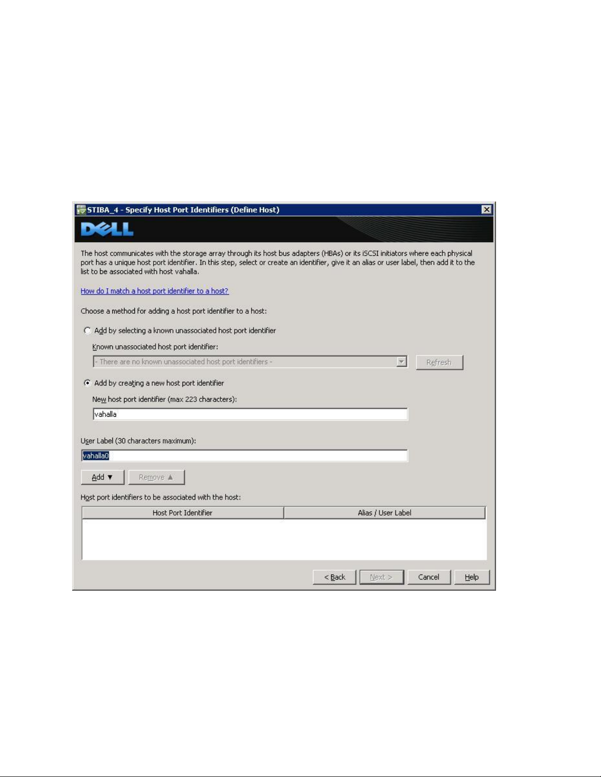
CONFIGURE STORAGE ARRAY SELECTION. THE NEW SERVER BEING ADDED TO AN EXISTING HOST GROUP IS NAMED “VALHALLA”.
FROM THE SETUP TAB
Page 6
Page 9
Dell PowerVault MD32xxi Configuration Guide for VMware ESX4.1 Server Software
1. SELECT MANUALLY DEFINE HOSTS.
2. ENTER THE HOST NAME FOR THE SERVER WHICH HAS THE ESX SERVER SOFTWARE IS INSTALLED.
3. SELECT VMWARE AS THE HOST TYPE.
From the next screen, specify the iSCSI Initiator by entering a name for the iSCSI initiator. The label is autopopulated from the server name.
Host Group configuration starts from the screen titled “Manually Define Hosts”. For ESX servers supporting
VMotion, HA, and DRS (Distributed Resource Scheduler), a host group must be defined so the MD32xxi storage
subsystem has a configured iSCSI path to each of the hosts.
Select “Yes: This host will share access to the same virtual disks with other hosts”
Page 7
Page 10
Dell PowerVault MD32xxi Configuration Guide for VMware ESX4.1 Server Software
If a new host group is desired select the radio button for that option and enter in a name for your host
group using standard host naming conventions (e.g. no spaces etc.).
Should you already have one or more host groups assigned, select the radio button enabling selection
from a drop down list of existing host groups. This option is to be used when configuring the second,
third, etc. host in a group. Once the host group is selected, previously configured hosts for that host group
will be displayed. Note that these are shown as VMware hosts.
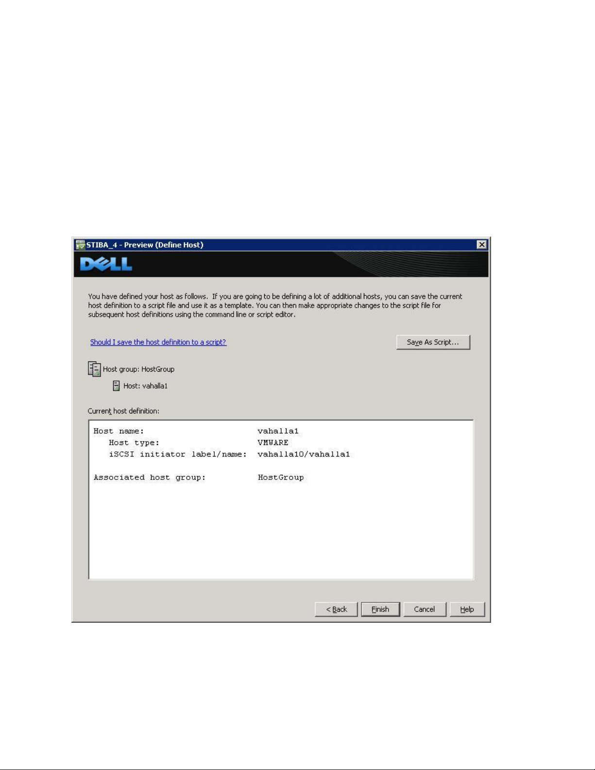
Selecting Next provides a Confirmation screen in which the new server being configured is shown and the other
previously configured associated hosts are named. For the first server configured in a new host group there will be
no associated hosts listed under the Associated host group.
Select Finish confirming the new host definition. This initiates the wizard configuration of the
new host.
Page 8
Page 11
Dell PowerVault MD32xxi Configuration Guide for VMware ESX4.1 Server Software
On completion,
Select Yes to proceed to the next host you wish to configure, or
Select No to end the configuration wizard.
Helpful Hint: Record the MD32xxi IP address for later configuration
iSCSI Software Initiator Configuration on ESX4.1 Server
This section lists the steps required to configure the software initiator on the VMware ESX4.1 Server. Connect to
the ESX4.1 server/vCenter using VI Client, and follow these steps:
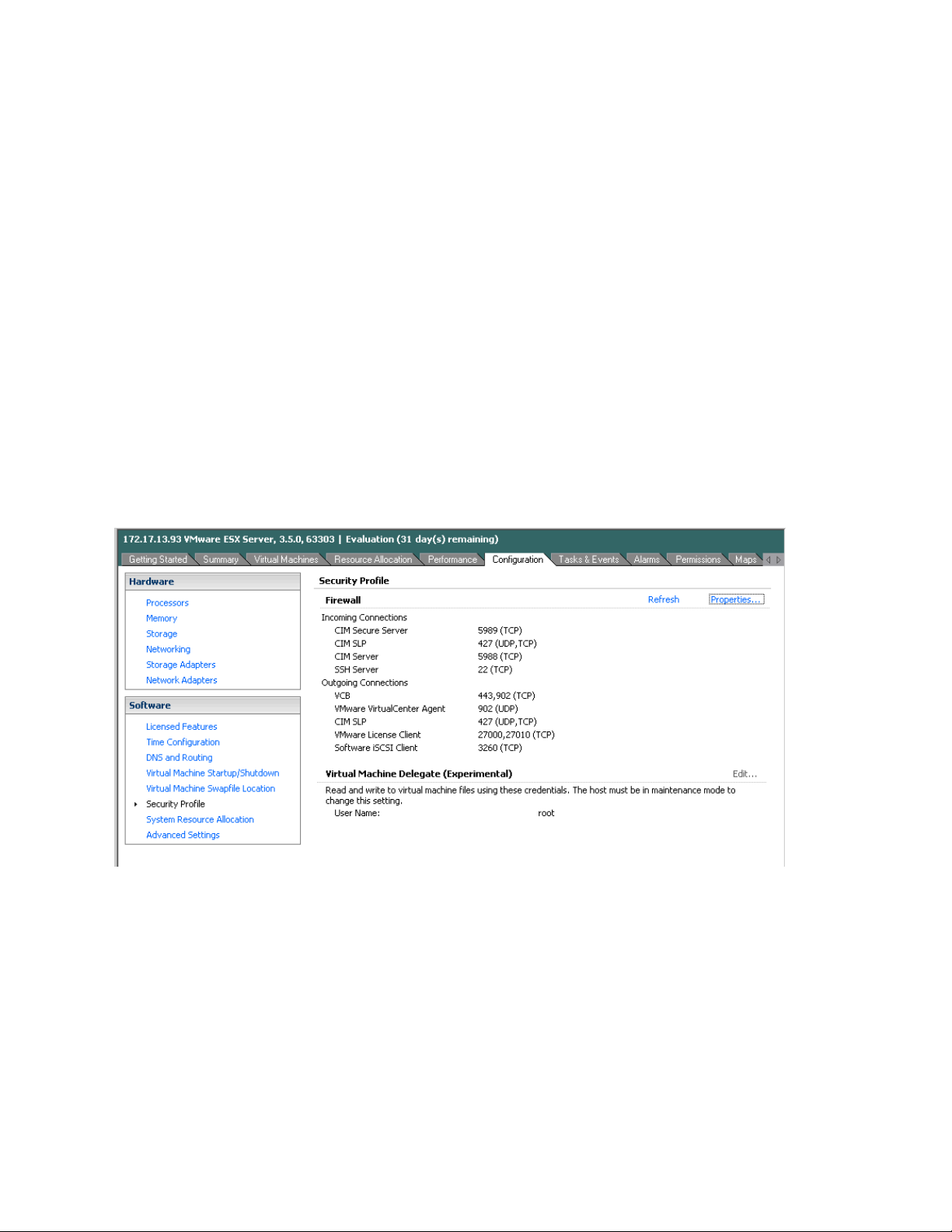
1. Select Configuration->Security Profile on the ESX server.
2. Click on Properties. The Firewall Properties box appears.
Page 9
Page 12
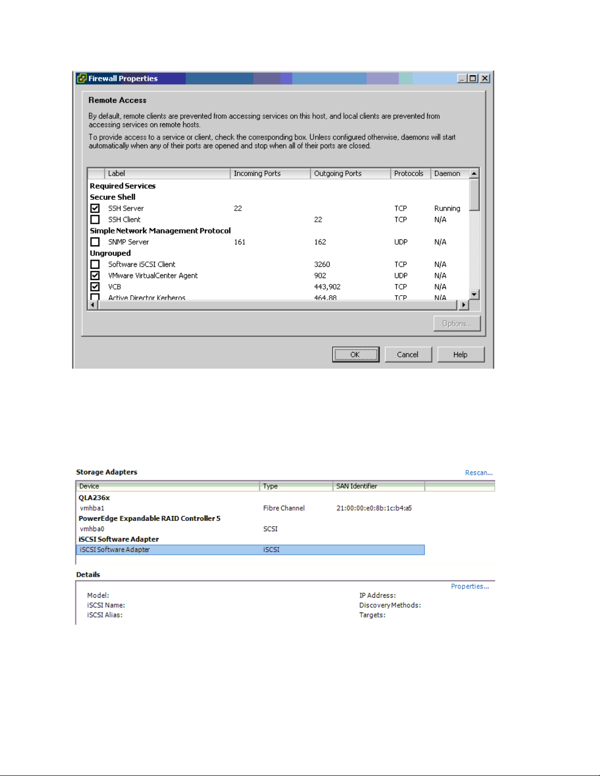
Dell PowerVault MD32xxi Configuration Guide for VMware ESX4.1 Server Software
3. Check Software iSCSI Client option.
4. Select Configuration->Storage Adapters on the ESX4.1 server.
5. Select iSCSI Software Adapter and click on Properties.
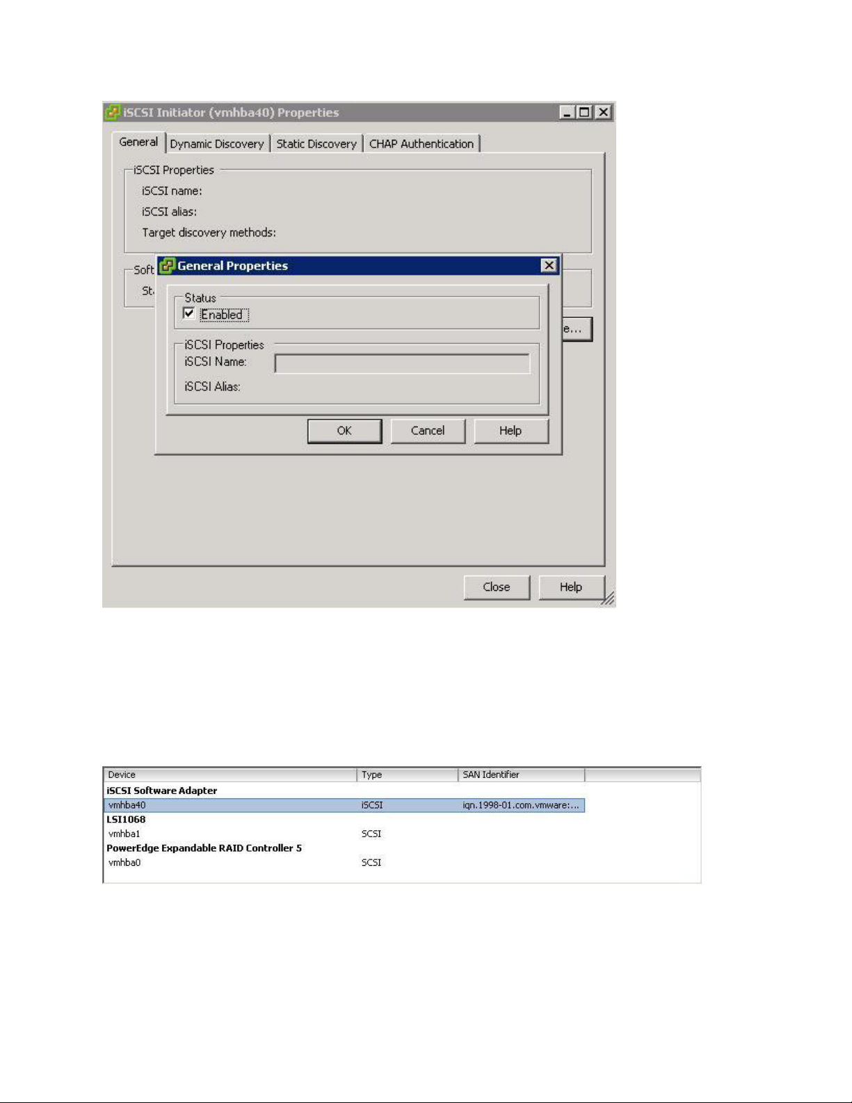
6. The iSCSI initiator Properties window appears.
7. Under the General tab select Configure tab. Select the Enabled checkbox and click OK. Select Close.
Page 10
Page 13
Dell PowerVault MD32xxi Configuration Guide for VMware ESX4.1 Server Software
8. Select iSCSI Software Adapter under Storage Adapters. You should now see your iSCSI Target name
listed.
9. Select Properties under storage adapters. Select Dynamic Discovery. Select Add. Provide the IP address
of the MD32xxi iSCSI Target Port and click OK. There may be a slight delay before the process completes.
Page 11
Page 14

Dell PowerVault MD32xxi Configuration Guide for VMware ESX4.1 Server Software
10. Click Close.
Clustering with ESX4.1 / Creating DRS Clusters
Refer to the following VMware website for a complete up-to-date list of the prerequisites for clustering with
ESX4.1 server.
http://www.vmware.com/pdf/vsphere4/r40/vsp_40_mscs.pdf
Configure iSCSI storage on ESX4.1 Server - Example
Installation Steps
Connect to the ESX server/vCenter using VI Client and follow the steps below.
Page 12
Page 15

Dell PowerVault MD32xxi Configuration Guide for VMware ESX4.1 Server Software
Go to the configuration tab and select Storage Adapters. Select the iSCSI Software Adapter and click Rescan. The
newly created iSCSI target and LUN should be visible from the ESX server.
Step1: Configure vSwitch & Enable Jumbo Frames
This step will create a new vSwitch and enable Jumbo Frame support for this switch. This step is used for
both examples no matter the number of VMkernels or physical NICs. Currently there is no option to
enable Jumbo Frames on a vSwitch from VMware vCenter GUI so these commands must be run via CLI. Be
sure to check the environment to make sure that Jumbo Frames are supported at the networking layer
before enabling it on the ESX host.
The following command will create a new vSwitch called vSwitch2:
esxcfg-vswitch –a vSwitch2
Next, enable Jumbo Frames on the vSwitch:
esxcfg-vswitch –m 9000 vSwitch2
To verify that the switch was configured properly run the following command:
esxcfg-vswitch –l
Your output will look similar to this:
Switch Name Num Ports Used Ports Configured Ports MTU Uplinks
vSwitch2 64 1 64 9000
You can note the new vSwitch2 with the MTU of 9000 to verify that the switch was created correctly. You
can also see it displayed in the GUI of vCenter. Throughout these procedures some of the verification can
be done via command line or seen in the vCenter GUI. The polling rate of vCenter is not instant so changes
will not show up immediately after it is typed.
Step2: Add iSCSI VMkernel Ports
This next step will assign VMkernel Ports to the new vSwitch2. It will also configure Jumbo Frame support
as well as assign the IP Addresses. Administrators familiar with iSCSI connectivity in ESX3.5 will find that it
is no longer required to configure a Service Console port for the iSCSI connection. Another thing to notice
is that because the Service Console is not needed, the iSCSI switch environment can be on a different
subnet than the public environment or existing service console. Each VMkernel Port will need its own IP
Address and they must all be on the same subnet and be on the same subnet as the PowerVault IP
Address.
Page 13
Page 16

Dell PowerVault MD32xxi Configuration Guide for VMware ESX4.1 Server Software
There are some suggested configurations depending on the number of NICs that will be used for iSCSI
traffic. Every environment will differ depending on the number of hosts, the number of members, and the
number of volumes.
In a default configuration assign one VMkernel port for each physical NIC in the system. So if there are 3
NICs, assign 3 VMkernel Ports. This is referred to in the VMware’s iSCSI SAN Configuration Guide as 1:1
port binding.
In the two examples provided, both a 1:1 relationship with 3 physical NICs and a 3:1 relationship with 2
physical NICs are shown.
VMware vCenter has a maximum of 8 connections to a single volume. In this whitepaper we choose 3
connections in the 1:1 scenario and 6 connections in the 3:1 scenario. This provides scalability and
performance as the SAN environment grows without having to make changes on each ESX host.
If fewer connections are desired follow the above sample configurations to obtain the number of
VMkernel Ports that match the environment and the number of paths you need.
Always keep the entire virtual datacenter in mind when deciding on path and volume count. View the
Release Notes of the PowerVault Firmware for the current connection limits for the Dell PowerVault.
All of these configurations are done for the vSwitch itself. This means that once it is done, the ESX4.1 host
will create multiple connections to the PowerVault SAN. Every new volume will have more connections as
well. Once this is configured there only need to be changes made if more NICs are being added or if more
or less paths are needed.
Note: Host profiles do not keep information on Jumbo Frames or Port Bindings.
For the rest of this whitepaper the configuration steps and commands will be given for the 1:1 binding.
See Appendix A for an example of the 3:1 VMkernel port binding.
The following command will add a new iSCSI VMkernel Port named iSCSI1 on the vSwitch created in the
previous step.
esxcfg-vswitch –A iSCSI1 vSwitch2
This next command will configure the IP Address, Subnet Mask and enable Jumbo Frame support for the
new VMkernel Port iSCSI1
esxcfg-vmknic –a –i 10.10.5.173 –n 255.255.255.0 –m 9000 iSCSI1
For our example with a 1:1 relationship with 3 NICs we need to create 2 more VMkernel Ports named
iSCSI2 and iSCSI3
esxcfg-vswitch –A iSCSI2 vSwitch2
esxcfg-vmknic –a –i 10.10.5.174 –n 255.255.255.0 –m 9000 iSCSI2
esxcfg-vswitch –A iSCSI3 vSwitch2
esxcfg-vmknic –a –i 10.10.5.175 –n 255.255.255.0 –m 9000 iSCSI3
Page 14
Page 17

Dell PowerVault MD32xxi Configuration Guide for VMware ESX4.1 Server Software
To verify the configuration enter the following command:
esxcfg-vswitch –l
The output will look similar to this:
Switch Name Num Ports Used Ports Configured Ports MTU Uplinks
vSwitch2 64 7 64 9000
PortGroup Name VLAN ID Used Ports Uplinks
iSCSI3 0 1
iSCSI2 0 1
iSCSI1 0 1
This will show the VMkernel ports that are assigned to the vSwitch. To verify the IP addresses enter the
following command:
esxcfg-vmknic –l
The output will look similar to the graphic below.
You can also verify the IP Addresses via the vCenter GUI. In vCenter, on the ESX Host, navigate to
Configuration -> Networking.
Step3: Assign Network Adapters
The next step in the process is to assign the network adapters (NICs) that will be attached to the iSCSI
network and used for iSCSI traffic. These will be attached to the vSwitch2 that we created earlier. This can
be done two ways, in the vCenter GUI or by CLI.
To list all of the adapters in the system run the following command:
Page 15
Page 18

Dell PowerVault MD32xxi Configuration Guide for VMware ESX4.1 Server Software
esxcfg-nics –l
The output will look similar to this:
Name PCI Driver Link Speed Duplex MAC Address MTU
vmnic0 03:00.00 bnx2 Up 1000Mbps Full 00:21:9b:8b:4b:b0 1500
This will list all of the adapters in the system. Assign the NICs that are physically connected to the SAN
infrastructure and to the vSwitch. The following command assumes that we are assigning vmnic1, vmnic2,
and vmnic3 to the vSwitch.
esxcfg-vswitch –L vmnic1 vSwitch2
esxcfg-vswitch –L vmnic2 vSwitch2
esxcfg-vswitch –L vmnic3 vSwitch2
Once again, to verify the configuration type the following command to list the vSwitch information:
esxcfg-vswitch –l
Your output will look similar to the following. Note the new vmnics that were assigned to the vSwitch
under uplinks.
Switch Name Num Ports Used Ports Configured Ports MTU Uplinks
vSwitch2 64 9 64 9000
PortGroup Name VLAN ID Used Ports Uplinks
iSCSI3 0 1 vmnic1,vmnic2,vmnic3
iSCSI2 0 1 vmnic1,vmnic2,vmnic3
iSCSI1 0 1 vmnic1,vmnic2,vmnic3
Adding a NIC can also be configured and verified in the vCenter GUI. Remember that the polling of
vCenter is not instant so a refresh might need to occur to see the latest changes. To configure this same
process from the GUI, first navigate to the Networking section on the ESX host you are configuring.
Configuration -> Networking.
From here, click Properties on the vSwitch2.
Page 16
Page 19

Dell PowerVault MD32xxi Configuration Guide for VMware ESX4.1 Server Software
Click the Network Adapters tab. Then click Add. This will open up the Add Adapter Wizard. From here
select the vmnics that you want to add to the vSwitch. In our example it will be vmnic1, vmnic2 and
vmnic3.
Page 17
Page 20

Dell PowerVault MD32xxi Configuration Guide for VMware ESX4.1 Server Software
Click Next after you have selected the chosen adapters. For now keep the defaults listed in the Failover
Order screen and click Next. Review the adapters listed and click Finish completing the process.
These adapters will now show up in the GUI under the Network Adapters tab.
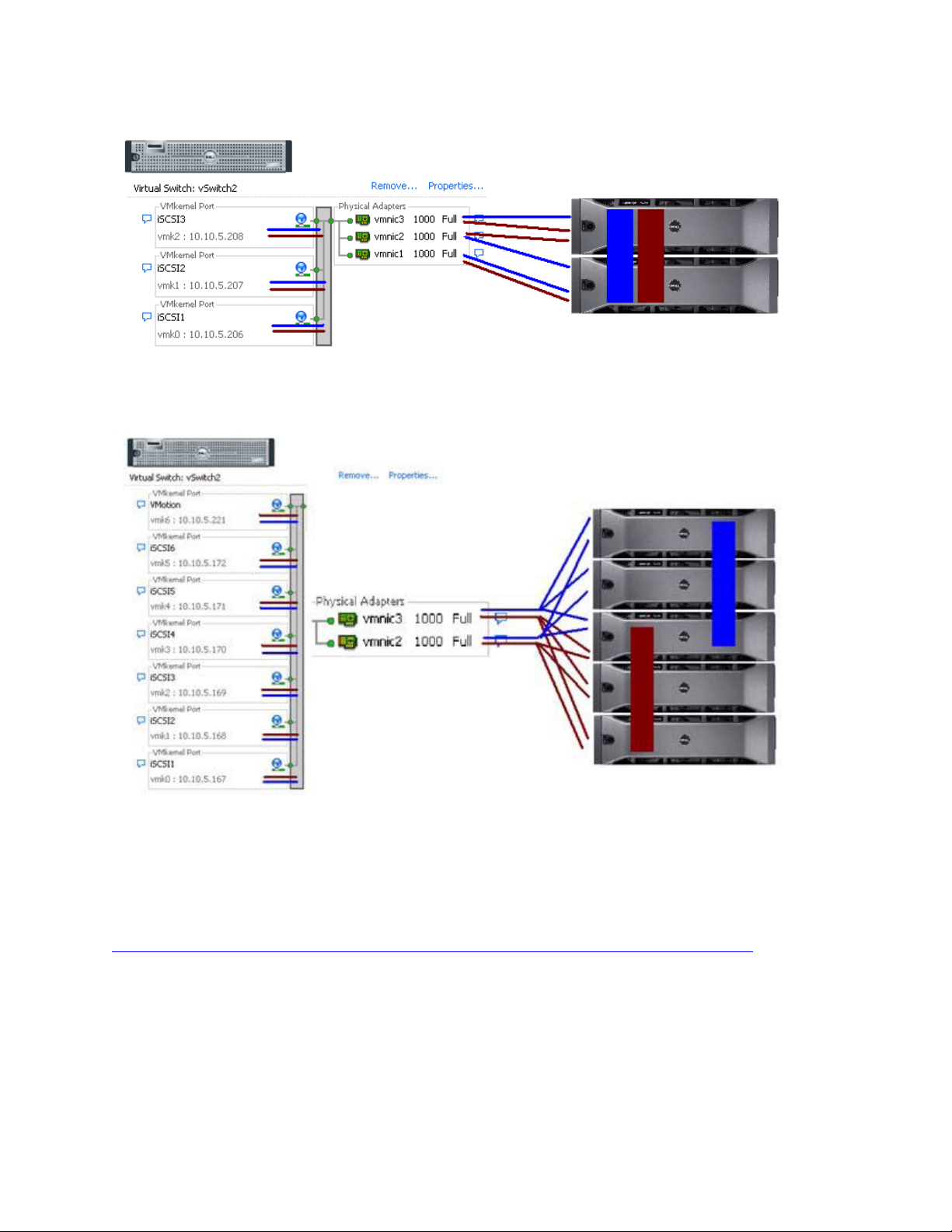
Step4: Associate VMkernel Ports to Physical Adapters
The next step is used to create the individual path bindings for each VMkernel to a NIC. This is required in
order to take advantage of the new advanced features such as Most Recently Used(MRU) MPIO or 3rd
party MPIO plug-ins available from Dell.
From our previous step there are 3 VMkernel ports and 3 NICs. This means that each NIC will have 1
VMkernel ports assigned to it. Again, each environment will differ and these numbers can change based
on the number of NICs and the number of paths assigned.
This process can be done either via CLI or through the vCenter GUI.
Page 18
Page 21

Dell PowerVault MD32xxi Configuration Guide for VMware ESX4.1 Server Software
By default, all the vmnics are assigned to each VMkernel port. We need to remove all but one vmnic from
each VMkernel port so that each VMkernel port has only one uplink.
Before running these commands the switch information looks like the following (obtained using esxcfg-
vswitch –l again):
Switch Name Num Ports Used Ports Configured Ports MTU Uplinks
vSwitch2 64 7 64 9000
PortGroup Name VLAN ID Used Ports Uplinks
iSCSI3 0 1 vmnic1,vmnic2,vmnic3
iSCSI2 0 1 vmnic1,vmnic2,vmnic3
iSCSI1 0 1 vmnic1,vmnic2,vmnic3
You can see that there are three vmnics in each uplink for each VMkernel Port. This is what we need to
change so that only a single vmnic is in each uplink and that we manually load balance them across all
available VMkernel Ports.
To configure this process via CLI first note the vmnic number of a NIC you want to remove and type the
following command:
esxcfg-vswitch –p iSCSI1 –N vmnic3 vSwitch2
What this will do is remove vmnic3 from VMkernel port iSCSI1 so that now vmnic1 and vmnic2 are left on
iSCSI1. We then need to remove vmnic2 so that only vmnic1 is associated with the iSCSI1. To do this type
the following command:
esxcfg-vswitch –p iSCSI1 –N vmnic2 vSwitch2
Now that we have just one vmnic associated with one VMkernel port we need to remove the excess NICs
on the other ports.
esxcfg-vswitch –p iSCSI2 –N vmnic1 vSwitch2
esxcfg-vswitch –p iSCSI2 –N vmnic3 vSwitch2
esxcfg-vswitch –p iSCSI3 –N vmnic1 vSwitch2
esxcfg-vswitch –p iSCSI3 –N vmnic2 vSwitch2
To verify that this was done correctly type the following command:
esxcfg-vswitch –l
The output will look similar to this:
Page 19
Page 22

Dell PowerVault MD32xxi Configuration Guide for VMware ESX4.1 Server Software
Switch Name Num Ports Used Ports Configured Ports MTU Uplinks
vSwitch2 64 7 64 9000
PortGroup Name VLAN ID Used Ports Uplinks
iSCSI3 0 1 vmnic3
iSCSI2 0 1 vmnic2
iSCSI1 0 1 vmnic1
The important thing to note is that under the Uplinks section there is only one vmnic assigned to each
iSCSI VMkernel port and that they are evenly distributed across them.
This can also be done through the vCenter GUI. To configure this from the GUI first navigate to the
Networking section on the ESX host you are configuring. Configuration -> Networking.
From here, click Properties on the vSwitch2.
Select one of the VMkernel Ports, in this example iSCSI1 and click Edit.
From here select the NIC Teaming tab.
Here you are going to select the check box for Override vSwitch failover order.
Just like in the CLI example we will assign vmnic1 to iSCSI1. This is done by selecting the adapters that are
not going to be assigned to the VMkernel (vmnic2 and vmnic3 in this case) and clicking the Move Down
button until it is listed under Unused Adapters. The following figure shows the completed result. Click Ok
to complete the process. Do this same thing for each of the iSCSI VMkernel ports so that each VMkernel
port is mapped to only one adapter and they are all balanced. In this example we assigned iSCSI1to
vmnic1, iSCSI2 to vmnic2 and iSCSI3 to vmnic3.
Page 20
Page 23

Dell PowerVault MD32xxi Configuration Guide for VMware ESX4.1 Server Software
Step5: Enable VMware iSCSI Software Initiator
The next step, if it has not been done already, is to enable the iSCSI initiator to prepare the ESX host to
connect to the PowerVault SAN. This can be done either through a CLI command or through the vCenter
GUI.
To enable the iSCSI initiator through the CLI type the following command:
esxcfg-swiscsi –e
Page 21
Page 24

Dell PowerVault MD32xxi Configuration Guide for VMware ESX4.1 Server Software
This will enable the software iSCSI initiator. To verify that it is enabled type the following command:
esxcfg-swiscsi –q
This can also be accomplished by using the vCenter GUI.
From the vCenter GUI on the ESX host navigate to Configuration -> Storage Adapters. Select the iSCSI
Software Adapter and click Properties.
Under the General tab click the Configure button. Place a check mark in Enabled and hit Ok. This will
enable the iSCSI initiator and assign a unique iqn to the ESX host. Administrators familiar with enabling
iSCSI in ESX 3.5 will notice that the firewall policies are automatically set when you enable it in vSphere4.
Page 22
Page 25

Dell PowerVault MD32xxi Configuration Guide for VMware ESX4.1 Server Software
Step6: Binding VMkernel Ports to iSCSI Software Initiator
This next step will bind the VMkernel ports, which were configured in Step 4 earlier, to the iSCSI Software
Initiator. If this step is skipped there will only ever be a single connection to the PowerVault SAN. This step
must be done via CLI.
The first thing to do is to note the vmhba# of the iSCSI Software Initiator. This can be seen in the vCenter
GUI on the ESX host under Configuration -> Storage Adapters.
This can also be found by running the following CLI command to discover all SCSI devices including the
iSCSI software adapter:
esxcfg-scsidevs –a
The output will look something like the following:
vmhba0 mptsas link-n/a sas.5001ec90e0ba7c00
(1:0.0) LSI Logic / Symbios Logic LSI1068E
vmhba1 ata_piix link-n/a ide.vmhba1
(0:31.1) Intel Corporation 631xESB/632xESB IDE Controller
vmhba32 ata_piix link-n/a ide.vmhba32
(0:31.1) Intel Corporation 631xESB/632xESB IDE Controller
vmhba33 iscsi_vmk link-n/a iscsi.vmhba33
() Software iSCSI
In this example from both the GUI and CLI we can determine that the vmhba# for the iSCSI Software
Initiator is vmhba33. This will be used in the next part. This will differ on various systems based on the
devices installed.
The next piece of information to gather is the vmk# of each of the VMkernel ports. This can be done via
the GUI or CLI.
To determine the vmk# of each VMkernel port from the vCenter GUI navigate to Configuration ->
Networking. From the vSwitch that was created earlier under each VMkernel port, the vmk# will be listed.
NOTE: It is important to recognize that they may not start with vmk0, vMotion ports and other VMkernels
will utilize the same numbers based on the order they are created.
Page 23
Page 26

Dell PowerVault MD32xxi Configuration Guide for VMware ESX4.1 Server Software
In this example we see that iSCSI1 is vmk0, iSCSI2 is vmk1, and iSCSI3 is vmk2. This is also information that
we need to note.
We can also see this in the CLI by using the following command:
esxcfg-vmknic –l
The output will look similar to this:
Interface Port Group/DVPort IP Family IP Address
Netmask Broadcast MAC Address MTU TSO MSS
Enabled Type
vmk0 iSCSI1 IPv4 10.10.5.173
255.255.255.0 10.10.5.255 00:50:56:7b:d8:3e 9000 65535 true
STATIC
vmk1 iSCSI2 IPv4 10.10.5.174
255.255.255.0 10.10.5.255 00:50:56:7e:ae:80 9000 65535 true
STATIC
vmk2 iSCSI3 IPv4 10.10.5.175
255.255.255.0 10.10.5.255 00:50:56:74:a4:e0 9000 65535 true
STATIC
We can determine this same information from the GUI.
Now that we know the vmhba# and the vmk# we can map each VMkernel Port to the iSCSI Software
Initiator. This is done through the CLI by typing the following command:
esxcli swiscsi nic add –n vmk0 –d vmhba33
This will bind the vmk0 VMkernel port to the iSCSI Software Adapter vmhba33. We then proceed to bind
all of the other vmk# to the same vmhba.
esxcli swiscsi nic add –n vmk1 –d vmhba33
esxcli swiscsi nic add –n vmk2 –d vmhba33
To verify that all of the vmk# are bound properly to the vmhba run the following command:
Page 24
Page 27

Dell PowerVault MD32xxi Configuration Guide for VMware ESX4.1 Server Software
esxcli swiscsi nic list –d vmhba33
This will list all of the information for VMkernel ports that are assigned to the iSCSI Software Adapter.
Step7: Connect to PowerVault MD32XXi Storage
Now that the advanced configuration for the vSphere4 iSCSI Software Initiator has been completed, the
next stage is to connect to the Dell PowerVault SAN and to the volumes it contains.
More information for complete administration of the Dell PowerVault SAN can be found in the
PowerVault User’s Guide. In this example we will attach the iSCSI Software Initiator to the SAN and to a
single volume. We will skip configuring CHAP but both one way and bi-directional CHAP is supported by
the PowerVault SAN.
The first thing to do is add the PowerVault IP Address to the dynamic discovery of the ESX Host iSCSI
Software Initiator. This is done to enable rescans to find new volumes that can be seen by ESX and used to
create Datastores.
To configure this, navigate in the vCenter GUI to Configuration -> Storage Adapters.
Click on the iSCSI Software Adapter and click Properties.
Click the Dynamic Discovery tab.
Click Add.
In the iSCSI Server box type in the IP Address of the PowerVault SAN and hit Ok.
Page 25
Page 28

Dell PowerVault MD32xxi Configuration Guide for VMware ESX4.1 Server Software
When this is done click Close or enter in another IP Address if there are multiple SANs in your
environment.
You will be prompted for a Rescan of the HBAs but at this time as there are no volumes assigned it is
unnecessary.
The next step will be to create a new volume and assign it to the ESX server. This can be done multiple
ways so refer to the PowerVault User’s Guide for more information. In this example we will create a
100GB Volume and assign it to this ESX host via the iqn name.
Create a new volume named ‘1’.
Page 26
Page 29

Dell PowerVault MD32xxi Configuration Guide for VMware ESX4.1 Server Software
1. Set the volume size and keep the rest of the defaults and click Finish.
Page 27
Page 30

Dell PowerVault MD32xxi Configuration Guide for VMware ESX4.1 Server Software
2. Under iSCSI Access you can choose to use an IP Address or Initiator Name.
3. To find the iSCSI Initiator Name from the vCenter GUI go to Configuration -> Storage Adapters. Click
on the iSCSI Software Adapter. The iqn can be copied and pasted into the Group Manager interface
for the Initiator Name.
There is another check box option for “Disallow un-named discovery sessions”.
Page 28
Page 31

Dell PowerVault MD32xxi Configuration Guide for VMware ESX4.1 Server Software
4. Check Disallow un-named discovery sessions, if desired.
Step8: Connect to a Volume on PowerVault SAN
The next step is to connect to the volume on the SAN and verify the connection status. Since the iSCSI
access and configuration was configured in the last step, the only thing to do now is to rescan the HBAs
and make sure the volume appears correctly.
In the vSphere4 GUI click on Configuration -> Storage Adapters and select the iSCSI Software Adapter.
Click Rescan All and choose to Scan for New Storage Devices and select Ok.
When this is done, if everything has been configured properly under Devices there will be a new
PowerVault iSCSI Disk with the correct size similar to what’s shown below.
Page 29
Page 32

Dell PowerVault MD32xxi Configuration Guide for VMware ESX4.1 Server Software
Step9: Enabling VMware Native Multipathing – MRU
One of the new advanced features that is enabled by configuring the iSCSI Software Initiator the way we
have is that now we can take advantage of MPIO by using MRU. This combined with the fan-out
intelligent design of the PowerVault group allows for greater and better bandwidth utilization than in
previous versions of ESX.
To configure MRU Multipathing on a volume, select the volume from the vCenter GUI. Configure ->
Storage. Right click and select Manage Paths. This will display the path information with the default of
fixed path.
To enable MRU select the drop down next to Path Selection and choose MRU(VMware). This will
reconfigure the volume to utilize a load balancing policy going across all available paths.
NOTE: This needs to be done for every existing and new volume that you want the MRU policy for.
To verify that all of the configuration settings were made correctly, in the PowerVault Storage Manager,
select the Volume and then click the Connections tab.
Step10: Create VMFS Datastores and Connect More Volumes
Now that the iSCSI Software vSwitch is set up and configured, follow steps 8-9 for each additional new
Volume that is created. Each Volume can also be formatted VMFS and utilized as normal.
Each existing Volume can be modified to allow multiple ESX servers to attach to it by adding the Initiator
Name in the Access Tab inside the Group Manager. See the PowerVault User’s Guide for more
information on adding more access control connections to a volume.
Contact Information
HTTP://SUPPORT.DELL.COM/SUPPORT/TOPICS/GLOBAL.ASPX/SUPPORT/PRODUCT_SUPPORT/PRODUCT_SUPPORT_CENTRAL?C=US&CS=5
55&L=EN&S=BIZReferences
VMware vSphere 4.1 Documentation:
Page 30
Page 33

Dell PowerVault MD32xxi Configuration Guide for VMware ESX4.1 Server Software
http://www.vmware.com/support/pubs/vs_pages/vsp_pubs_esxi41_e_vc41.html
Dell/VMware alliance home page:
http://www.dell.com/vmware
Appendix A
This appendix details an example of how to over commit the number of VMkernel ports to the physical NICs. This is
usually done in environments in which the NIC is capable of handling multiple sessions such as 10GbE. This can also
be done in larger environments combined with a PowerVault SAN to help achieve maximum bandwidth to the
SAN.
In this appendix example we are using 2 physical NICs and assigning 3 VMkernel ports to each one for a total of 6
sessions to the SAN.
Step A1: Configure vSwitch and Enable Jumbo Frames
Follow the Step 1 configuration steps in the main document as there are no changes for adding multiple
VMkernel ports.
Step A2: Add iSCSI VMkernel Ports
The following command will add a new iSCSI VMkernel Port named iSCSI1 on the vSwitch created in the
previous step.
esxcfg-vswitch –A iSCSI1 vSwitch2
This next command will configure the IP Address, Subnet Mask and enable Jumbo Frame support for the
new VMkernel Port iSCSI1
esxcfg-vmknic –a –i 10.10.5.173 –n 255.255.255.0 –m 9000 iSCSI1
Following the example from before we are just adding more VMkernel ports. We need to create 5 more
VMkernel Ports named iSCSI2, iSCSI3, iSCSI4, iSCSI5 and iSCSI6. Then configure the IP addresses, subnet
masks and enable Jumbo Frames.
esxcfg-vswitch –A iSCSI2 vSwitch2
esxcfg-vmknic –a –i 10.10.5.174 –n 255.255.255.0 –m 9000 iSCSI2
esxcfg-vswitch –A iSCSI3 vSwitch2
Page 31
Page 34

Dell PowerVault MD32xxi Configuration Guide for VMware ESX4.1 Server Software
esxcfg-vmknic –a –i 10.10.5.175 –n 255.255.255.0 –m 9000 iSCSI3
esxcfg-vswitch –A iSCSI4 vSwitch2
esxcfg-vmknic –a –i 10.10.5.176 –n 255.255.255.0 –m 9000 iSCSI4
esxcfg-vswitch –A iSCSI5 vSwitch2
esxcfg-vmknic –a –i 10.10.5.177 –n 255.255.255.0 –m 9000 iSCSI5
esxcfg-vswitch –A iSCSI6 vSwitch2
esxcfg-vmknic –a –i 10.10.5.178 –n 255.255.255.0 –m 9000 iSCSI6
To create less VMkernel Ports just skip iSCSI5 and iSCSI6 for example.
To verify the configuration enter the following command:
esxcfg-vswitch –l
This will show the VMkernel ports that are assigned to the vSwitch. To verify the IP addresses enter the
following command:
esxcfg-vmknic –l
You can also verify the IP Addresses via the vCenter GUI. Navigate to Configuration ->
Networking.
Page 32
Page 35

Dell PowerVault MD32xxi Configuration Guide for VMware ESX4.1 Server Software
Step A3: Assign Network Adapters
Just like in the previous example, the next step in the process is to assign the network adapters (NICs) that
will be attached to the iSCSI network and used for iSCSI traffic. These will be attached to the vSwitch2 that
we created earlier. This can be done two ways, in the vCenter GUI or by CLI.
To list all of the adapters in the system run the following command:
esxcfg-nics –l
This will list all of the adapters in the system. Assign the NICs that are physically connected to the SAN
infrastructure and to the vSwitch. The following command assumes that we are assigning vmnic2 and
vmnic3 to the vSwitch.
esxcfg-vswitch –L vmnic2 vSwitch2
esxcfg-vswitch –L vmnic3 vSwitch2
Once again to verify the configuration type the following command to list the vSwitch information:
esxcfg-vswitch –l
Your output will look similar to the following. Note the new vmnics that were assigned to the vSwitch
under uplinks.
Switch Name Num Ports Used Ports Configured Ports MTU Uplinks
vSwitch2 64 9 64 9000 vmmnic3,vmnic2
PortGroup Name VLAN ID Used Ports Uplinks
iSCSI6 0 1 vmnic2,vmnic3
iSCSI5 0 1 vmnic2,vmnic3
iSCSI4 0 1 vmnic2,vmnic3
iSCSI3 0 1 vmnic2,vmnic3
iSCSI2 0 1 vmnic2,vmnic3
iSCSI1 0 1 vmnic2,vmnic3
This can also be configured and verified in the vCenter GUI. Remember that the polling of vCenter is not
instant so a refresh might need to occur to see the latest changes. To configure this same process from
the GUI, first navigate to the Networking section on the ESX host you are configuring. Configuration ->
Networking.
From here, click Properties on the vSwitch2.
Page 33
Page 36

Dell PowerVault MD32xxi Configuration Guide for VMware ESX4.1 Server Software
Click the Network Adapters tab. Then click Add. This will open up the Add Adapter Wizard. From here
select the vmnics that you want to add to the vSwitch. In our example it will be vmnic2 and vmnic3.
Click Next after you have selected the chosen adapters. For now keep the defaults listed in the Failover
Order screen and click Next. Review the adapters listed and click Finish completing the process.
These adapters will now show up in the GUI under the Network Adapters tab.
Step A4: Associate VMkernel Ports to Physical Adapters
The next step is used to create the individual path bindings for each VMkernel to a NIC. This is required in
order to take advantage of the new advanced features such as Round Robin MPIO or 3rd party MPIO plugins that will be available from Dell.
From our previous step there are 6 VMkernel ports and 2 NICs. This means that each NIC will have 3
VMkernel ports assigned to it. Again, each environment will differ and these numbers can change based
on the number of NICs and the number of paths assigned. If we ever add a third NIC then we would
rebalance the number of VMkernel ports to two ports per NIC.
This process can be done either via CLI or through the vCenter GUI.
By default, both vmnic2 and vmnic3 are assigned to each VMkernel port. We need to remove one vmnic
from each VMkernel port so that each VMkernel port has only one uplink.
Before running these commands the switch information looks like the following (obtained using esxcfgvswitch –l again):
Page 34
Page 37

Dell PowerVault MD32xxi Configuration Guide for VMware ESX4.1 Server Software
Switch Name Num Ports Used Ports Configured Ports MTU Uplinks
vSwitch2 64 9 64 9000 vmnic3,vmnic2
PortGroup Name VLAN ID Used Ports Uplinks
iSCSI6 0 1 vmnic2,vmnic3
iSCSI5 0 1 vmnic2,vmnic3
iSCSI4 0 1 vmnic2,vmnic3
iSCSI3 0 1 vmnic2,vmnic3
iSCSI2 0 1 vmnic2,vmnic3
iSCSI1 0 1 vmnic2,vmnic3
You can see that there are two vmnics in each uplink for each VMkernel Port. This is what we need to
change so that only a single vmnic is in each uplink and that we manually load balance them across all
available VMkernel Ports.
To configure this process via CLI first note the vmnic number of the NICs you want to remove and type the
following command:
esxcfg-vswitch –p iSCSI1 –N vmnic3 vSwitch2
What this will do is remove vmnic3 from VMkernel port iSCSI1 so that just vmnic2 is on iSCSI1.
We then need to do the same thing for the other 4 VMkernel ports making sure to remove vmnics so that
an equal number of VMkernel ports are on each vmnic (3 per vmnic).
esxcfg-vswitch –p iSCSI2 –N vmnic3 vSwitch2
esxcfg-vswitch –p iSCSI3 –N vmnic3 vSwitch2
esxcfg-vswitch –p iSCSI4 –N vmnic2 vSwitch2
esxcfg-vswitch –p iSCSI5 –N vmnic2 vSwitch2
esxcfg-vswitch –p iSCSI6 –N vmnic2 vSwitch2
In an example where there are 3 or more vmnics, you would remove each one from the vSwitch to make
sure there is only a single vmnic per uplink.
To verify that this was done correctly type the following command:
esxcfg-vswitch –l
The output will look similar to this:
Switch Name Num Ports Used Ports Configured Ports MTU Uplinks
vSwitch2 64 9 64 9000 vmnic3,vmnic2
PortGroup Name VLAN ID Used Ports Uplinks
iSCSI6 0 1 vmnic3
iSCSI5 0 1 vmnic3
iSCSI4 0 1 vmnic3
iSCSI3 0 1 vmnic2
iSCSI2 0 1 vmnic2
iSCSI1 0 1 vmnic2
Page 35
Page 38

Dell PowerVault MD32xxi Configuration Guide for VMware ESX4.1 Server Software
The important thing to note is that under the Uplinks section there is only one vmnic assigned to each
iSCSI VMkernel port and that they are evenly distributed across them all.
This can also be done through the vCenter GUI. To configure this from the GUI first navigate to the
Networking section on the ESX host you are configuring. Configuration -> Networking.
From here, click Properties on the vSwitch2.
Select one of the VMkernel Ports, in this example iSCSI1 and click Edit.
From here select the NIC Teaming tab.
Here you are going to select the check box for Override vSwitch Failover Order.
Just like in the CLI example we will assign vmnic2 to iSCSI1. This is done by selecting the adapter that is
not going to be assigned to the VMkernel (vmnic3 in this case) and clicking the Move Down button until it
is listed under Unused Adapters. Click Ok to complete the process. Do this same thing for each of the iSCSI
VMkernel ports so that each VMkernel port is mapped to only one adapter and they are balanced across
them all. In this example we assigned iSCSI1, iSCSI2 and iSCSI3 to vmnic2 and assigned iSCSI4, iSCSI5 and
iSCSI6 to vmnic3.
Step A5: Enable VMware iSCSI Software Initiator
The next step, if it has not been done already, is to enable the iSCSI initiator to prepare the ESX host to
connect to the PowerVault SAN. This can be done either through a CLI command or through the vCenter
GUI.
To enable the iSCSI initiator through the CLI type the following command:
esxcfg-swiscsi –e
This will enable the software iSCSI initiator. To verify that it is enabled type the following
command:
esxcfg-swiscsi –q
This can also be accomplished by using the vCenter GUI.
From the GUI first navigate to Configuration -> Storage Adapters. Select the iSCSI Software Adapter and
click Properties.
Under the General tab click the Configure button. Place a check mark in Enabled and hit Ok.
This will enable the iSCSI initiator and assign a unique iqn to the ESX host.
Step A6: Binding VMkernel Ports to iSCSI Software Initiator
This next step will bind the VMkernel ports that were configured in Step 4 earlier, to the iSCSI Software
Initiator. If this step is skipped there will only ever be a single connection to the PowerVault SAN. This step
must be done via CLI.
Page 36
Page 39

Dell PowerVault MD32xxi Configuration Guide for VMware ESX4.1 Server Software
The first thing to do is to note the vmhba# of the iSCSI Software Initiator. This can be seen in the vCenter
GUI under Configuration -> Storage Adapters.
This can also be found by running the following CLI command to discover all SCSI devices including the
iSCSI software adapter:
esxcfg-scsidevs –a
The output will look something like the following:
vmhba33 iscsi_vmk link-n/a iscsi.vmhba33
() Software iSCSI
In this example from both the GUI and CLI we can determine that the vmhba# for the iSCSI Software
Initiator is vmhba33. This will be used in the next part. This will differ on various systems based on the
devices installed.
The next piece of information to gather is the vmk# of each of the VMkernel ports. This can be done via
the GUI or CLI.
To determine the vmk# of each VMkernel port from the GUI navigate to Configuration -> Networking.
From the vSwitch that was created earlier under each VMkernel port, the vmk# will be listed.
NOTE: It is important to recognize that they may not start with vmk0, VMotion ports and other VMkernels
will utilize the same numbers based on the order they are created.
Page 37
Page 40

Dell PowerVault MD32xxi Configuration Guide for VMware ESX4.1 Server Software
In this example we see that iSCSI1 is vmk0, iSCSI2 is vmk1, iSCSI3 is vmk2 and iSCSI4 is vmk3. This is also
information that we need to note.
We can also see this in the CLI by using the following command:
esxcfg-vmknic –l
The output will look similar to this:
Interface Port Group/DVPort IP Family IP Address
Netmask Broadcast MAC Address MTU TSO MSS
Enabled Type
vmk0 iSCSI1 IPv4 10.10.5.173
255.255.255.0 10.10.5.255 00:50:56:7b:d8:3e 9000 65535 true
STATIC
vmk1 iSCSI2 IPv4 10.10.5.174
255.255.255.0 10.10.5.255 00:50:56:7e:ae:80 9000 65535 true
STATIC
vmk2 iSCSI3 IPv4 10.10.5.175
255.255.255.0 10.10.5.255 00:50:56:74:a4:e0 9000 65535 true
STATIC
vmk3 iSCSI4 IPv4 10.10.5.176
255.255.255.0 10.10.5.255 00:50:56:70:80:a7 9000 65535 true
STATIC
vmk4 iSCSI5 IPv4 10.10.5.177
255.255.255.0 10.10.5.255 00:50:56:77:f2:64 9000 65535 true
STATIC
vmk5 iSCSI6 IPv4 10.10.5.178
Page 38
Page 41

Dell PowerVault MD32xxi Configuration Guide for VMware ESX4.1 Server Software
255.255.255.0 10.10.5.255 00:50:56:7d:b5:f2 9000 65535 true
STATIC
We can determine the same information as was found from the GUI.
Now that we know the vmhba# and the vmk# we can map each VMkernel Port to the iSCSI Software
Initiator. This is done through the CLI by typing the following command:
esxcli swiscsi nic add –n vmk0 –d vmhba33
This will bind the vmk0 VMkernel port to the iSCSI Software Adapter vmhba33. We then proceed to bind
all of the other vmk# to the same vmhba.
esxcli swiscsi nic add –n vmk1 –d vmhba33
esxcli swiscsi nic add –n vmk2 –d vmhba33
esxcli swiscsi nic add –n vmk3 –d vmhba33
esxcli swiscsi nic add –n vmk4 –d vmhba33
esxcli swiscsi nic add –n vmk5 –d vmhba33
To verify that all of the vmk# are bound properly to the vmhba run the following command:
esxcli swiscsi nic list –d vmhba33
This will list all of the information for VMkernel ports that are assigned to the iSCSI Software Adapter.
Step A7: Connect to the Dell PowerVault Storage
Now that the iSCSI initiator has been configured properly, follow steps 7 through 10 above to assign the
new volumes and make them available for use.
One thing you will note is the increased number of connections seen in the connection tab of the volume
inside the PowerVault Storage administrator.
Page 39
 Loading...