

Page 1
Midi-Lathe
Tour Midi-Lathe
LA200
Torno Midi
A17997_Rev. B_09-20-06
Copyright © 2006 Delta Machinery
Instruction Manual
Manuel d’Utilisation
Manual de Instrucciones
FRANÇAIS (22) ESPAÑOL (42)
www.deltamachinery.com
(800) 223-7278 - US
(800) 463-3582 - CANADA
Page 2

TABLE OF CONTENTS
IMPORTANT SAFETY INSTRUCTIONS ....................2
SAFETY GUIDELINES - DEFINITIONS .....................2
GENERAL SAFETY RULES .......................................3
ADDITIONAL SPECIFIC SAFETY RULES ................4
FUNCTIONAL DESCRIPTION ...................................6
CARTON CONTENTS ...............................................6
ASSEMBL Y .................................................................7
OPERA TION ...............................................................10
TROUBLESHOOTING ................................................20
MAINTENANCE ..........................................................20
SERVICE .....................................................................20
ACCESSORIES ...........................................................21
WARRANTY ................................................................21
FRANÇAIS ..................................................................22
ESPAÑOL ....................................................................42
IMPORTANT SAFETY INSTRUCTIONS
Read and understand all warnings and operating instructions before using any tool
or equipment. When using tools or equipment, basic safety precautions should always be followed
to reduce the risk of personal injury. Improper operation, maintenance or modification of tools or
equipment could result in serious injury and property damage. There are certain applications for which
tools and equipment are designed. Delta Machinery strongly recommends that this product NOT be modified and/or
used for any application other than for which it was designed.
If you have any questions relative to its application DO NOT use the product until you have written Delta Machinery and
we have advised you. Contact us online at www.deltamachinery.com or by mail at Technical Service Manager, Delta
Machinery, 4825 Highway 45 North, Jackson, TN 38305. In Canada,125 Mural St. Suite 300, Richmond Hill, ON, L4B 1M4)
Information regarding the safe and proper operation of this tool is available fr om the following sources:
• Power Tool Institute, 1300 Sumner Avenue, Cleveland, OH 44115-2851or online at www.powertoolinstitute.org
• National Safety Council, 1121 Spring Lake Drive, Itasca, IL 60143-3201
• American National Standards Institute, 25 W est 43r d Street, 4 floor, New York, NY 10036 www .ansi.org - ANSI 01.1
Safety Requirements for Woodworking Machines
• U.S. Department of Labor regulations www .osha.gov
SAVE THESE INSTRUCTIONS!
SAFETY GUIDELINES - DEFINITIONS
It is important for you to read and understand this manual. The information it contains relates to protecting YOUR SAFETY
and PREVENTING PROBLEMS. The symbols below are used to help you recognize this information.
Indicates an imminently hazardous situation which, if not avoided, will result in death or serious
injury.
Indicates a potentially hazardous situation which, if not avoided, could result in death or serious
injury.
Indicates a potentially hazardous situation which, if not avoided, may result in minor or moderate
injury.
Used without the safety alert symbol indicates a potentially hazardous situation which, if not avoided,
may result in property damage.
CALIFORNIA PROPOSITION 65
Some dust created by power sanding, sawing, grinding, drilling, and other construction activities
contains chemicals known to cause cancer, birth defects or other reproductive harm. Some
examples of these chemicals are:
• lead from lead-based paints,
• crystalline silica from bricks and cement and other masonry products, and
• arsenic and chromium from chemically-treated lumber.
Your risk from these exposures varies, depending on how often you do this type of work. To reduce your
exposure to these chemicals: work in a well ventilated area, and work with approved safety equipment, al ways
wear NIOSH/OSHA approved, properly fit ting face mask or res pi ra tor when us ing such tools.
2
Page 3

GENERAL SAFETY RULES
Failure to follow these rules may result in serious personal injury.
1. FOR YOUR OWN SAFETY, READ THE INSTRUCTION
MANUAL BEFORE OPERATING THE MACHINE. Learning
the machine’s application, limitations, and specific hazards
will greatly minimize the possibility of accidents and injury.
2. WEAR EYE AND HEARING PROTECTION. ALWAYS
USE SAFETY GLASSES. Everyday eyeglasses are NOT
safety glasses. USE CERTIFIED SAFETY EQUIPMENT.
Eye protection equipment should comply with ANSI Z87.1
standards. Hearing equipment should comply with ANSI
S3.19 standards.
3. WEAR PROPER APPAREL. Do not wear loose clothing,
gloves, neckties, rings, bracelets, or other jewelry which may
get caught in moving parts. Nonslip protective footwear is
recommended. Wear protective hair covering to contain long
hair .
4. DO NOT USE THE MACHINE IN A DANGEROUS
ENVIRONMENT. The use of power tools in damp or wet
locations or in rain can cause shock or electrocution. Keep
your work area well-lit to prevent tripping or placing arms,
hands, and fingers in danger .
5. MAINTAIN ALL TOOLS AND MACHINES IN PEAK
CONDITION. Keep tools sharp and clean for best and safest
performance. Follow instructions for lubricating and changing
accessories. Poorly maintained tools and machines can further
damage the tool or machine and/or cause injury.
6. CHECK FOR DAMAGED PARTS. Before using the machine,
check for any damaged parts. Check for alignment of moving
parts, binding of moving parts, breakage of parts, and any
other conditions that may affect its operation. A guard or any
other part that is damaged should be properly repaired or
replaced with Delta or factory authorized replacement
parts. Damaged parts can cause further damage to the
machine and/or injury.
7. KEEP THE WORK AREA CLEAN. Cluttered areas and benches
invite accidents.
8. KEEP CHILDREN AND VISITORS AWAY. Your shop is a
potentially dangerous environment. Children and visitors can be
injured.
9. REDUCE THE RISK OF UNINTENTIONAL STARTING. Make
sure that the switch is in the “OFF” position before plugging
in the power cord. In the event of a power failure, move the
switch to the “OFF” position. An accidental start-up can cause
injury. Do not touch the plug’s metal prongs when unplugging
or plugging in the cord.
10. USE THE GUARDS. Check to see that all guards are in place,
secured, and working correctly to prevent injury.
11. REMOVE ADJUSTING KEYS AND WRENCHES BEFORE
STARTING THE MACHINE. Tools, scrap pieces, and other
debris can be thrown at high speed, causing injury .
12. USE THE RIGHT MACHINE. Don’t force a machine or an
attachment to do a job for which it was not designed. Damage
to the machine and/or injury may result.
13. USE RECOMMENDED ACCESSORIES. The use of
accessories and attachments not recommended by Delta
may cause damage to the machine or injury to the user .
14. USE THE PROPER EXTENSION CORD. Make sure your
extension cord is in good condition. When using an extension
cord, be sure to use one heavy enough to carry the current
your product will draw. An undersized cord will cause a drop
in line voltage, resulting in loss of power and overheating. See
the Extension Cord Chart for the correct size depending on
the cord length and nameplate ampere rating. If in doubt, use
the next heavier gauge. The smaller the gauge number, the
heavier the cord.
15. SECURE THE WORKPIECE. Use clamps or a vise to hold the
workpiece when practical. Loss of control of a workpiece can
cause injury.
16. FEED THE WORKPIECE AGAINST THE DIRECTION OF
THE ROTATION OF THE BLADE, CUTTER, OR ABRASIVE
SURFACE. Feeding it from the other direction will cause the
workpiece to be thrown out at high speed.
17. DON’T FORCE THE WORKPIECE ON THE MACHINE.
Damage to the machine and/or injury may result.
18. DON’T OVERREACH. Loss of balance can make you fall into
a working machine, causing injury.
19. NEVER STAND ON THE MACHINE. Injury could occur if the tool
tips, or if you accidentally contact the cutting tool.
20. NEVER LEAVE THE MACHINE RUNNING UNATTENDED.
TURN THE POWER OFF. Don’t leave the machine until it comes
to a complete stop. A child or visitor could be injured.
21. TURN THE MACHINE “OFF”, AND DISCONNECT THE
MACHINE FROM THE POWER SOURCE before installing or
removing accessories, changing cutters, adjusting or changing
set-ups. When making repairs, be sure to lock the start switch
in the “OFF” position. An accidental start-up can cause injury .
22. MAKE YOUR WORKSHOP CHILDPROOF WITH
PADLOCKS, MASTER SWITCHES, OR BY REMOVING
STARTER KEYS. The accidental start-up of a machine by a
child or visitor could cause injury.
23. STAY ALERT, WATCH WHAT YOU ARE DOING, AND USE
COMMON SENSE. DO NOT USE THE MACHINE WHEN
YOU ARE TIRED OR UNDER THE INFLUENCE OF DRUGS,
ALCOHOL, OR MEDICA TION. A moment of inattention while
operating power tools may result in injury .
24. USE OF THIS TOOL CAN GENERATE AND
DISBURSE DUST OR OTHER AIRBORNE PARTICLES,
INCLUDING WOOD DUST, CRYSTALLINE SILICA DUST
AND ASBESTOS DUST. Direct particles away from face
and body. Always operate tool in well ventilated area and
provide for proper dust removal. Use dust collection system
wherever possible. Exposure to the dust may cause serious
and permanent respiratory or other injury, including silicosis (a
serious lung disease), cancer, and death. Avoid breathing the
dust, and avoid prolonged contact with dust. Allowing dust to
get into your mouth or eyes, or lay on your skin may promote
absorption of harmful material. Always use properly fitting
NIOSH/OSHA approved respiratory protection appropriate for
the dust exposure, and wash exposed areas with soap and
water .
3
Page 4

ADDITIONAL SPECIFIC SAFETY RULES
Failure to follow these rules may result in serious personal injury.
1. DO NOT OPERATE THIS MACHINE UNTIL it is
assembled and installed according to the instructions.
2. OBTAIN ADVICE from your supervisor, instructor, or
another qualified person if you are not familiar with the
operation of this machine.
3. FOLLOW ALL WIRING CODES and recommended
electrical connections.
4. ROUGH CUT THE WORKPIECE as close as possible to
the finished shape before installing it on the faceplate.
5. EXAMINE THE WORKPIECE FOR FLAWS and test glue
joints before mounting the workpiece on machine. DO
NOT mount a split workpiece or one containing a knot.
6. SECURELY FASTEN THE WORKPIECE to the faceplate
prior to faceplate turning. Use the appropriate size
faceplate to properly support the workpiece. Do not let
the screw fasteners interfere with the turning tool at the
finished dimension of the workpiece.
7. NEVER DRIVE THE WORKPIECE into the drive center
while the drive center is in the headstock. Set the drive
center into the workpiece with a soft mallet prior to
installing it on the headstock.
8. SNUG THE TAILSTOCK CENTER against the workpiece
and lock it. Lubricate the tailstock center if it is not a ball
bearing center.
9. PROPERLY ADJUST THE TOOL REST HEIGHT.
10. ADJUST THE TOOL REST so it is as close to the
workpiece as possible.
11. TIGHTEN ALL CLAMP LOCKING HANDLES before
operating.
12. ROTATE THE WORKPIECE BY HAND to check clearance
before turning the machine “ON”.
13. CLEAR THE LATHE BED OF ALL OBJECTS (tools, scraps
of wood, etc.) before turning the machine “ON”.
14. EXAMINE THE SET-UP CAREFULLY before turning the
machine “ON”.
15. STAND CLEAR, AND KEEP ALL OBSERVERS AND
PASSERSBY clear of rotating path of workpiece to avoid
injury from flying debris.
16. USE THE LOWEST SPEED when starting a new
workpiece. NEVER EXCEED recommended speeds.
17. NEVER ADJUST THE TOOL REST while the workpiece is
turning.
18. NEVER LOOSEN THE TAILSTOCK SPINDLE or the
tailstock while workpiece is turning.
19. MOVE THE CUTTING TOOL INTO THE WORKPIECE
SLOWLY, and cut small amounts when roughing.
20. REMOVE THE TOOL REST before sanding or polishing.
21. NEVER PERFORM LAYOUT, assembly, or set-up work
on the table/work area when the machine is running.
22. TURN THE MACHINE “OFF” AND DISCONNECT THE
MACHINE from the power source before installing or
removing accessories, before adjusting or changing setups, or when making repairs.
23. TURN THE MACHINE “OFF”, disconnect the machine
from the power source, and clean the table/work area
before leaving the machine. LOCK THE SWITCH IN THE
“OFF” POSITION to prevent unauthorized use.
24. ADDITIONAL INFORMATION
proper operation of power tools (i.e. a safety video)
is available from the Power Tool Institute, 1300
Sumner Avenue, Cleveland, OH 44115-2851 (www.
powertoolinstitute.com). Information is also available
from the National Safety Council, 1121 Spring Lake
Drive, Itasca, IL 60143-3201. Please refer to the
American National Standards Institute ANSI 01.1 Safety
Requirements for Woodworking Machines and the
U.S. Department of Labor OSHA 1910.213 Regulations.
regarding the safe and
SAVE THESE INSTRUCTIONS.
Refer to them often and use them to instruct others.
4
Page 5
POWER CONNECTIONS
A separate electrical circuit should be used for your machines. This circuit should not be less than #12 wire and should
be protected with a 20 Amp time lag fuse. If an extension cord is used, use only 3-wire extension cords which have
3-prong grounding type plugs and matching receptacle which will accept the machine’s plug. Before connecting the
machine to the power line, make sure the switch (s) is in the “OFF” position and be sure that the electric current is of
the same characteristics as indicated on the machine. All line connections should make good contact. Running on low
voltage will damage the machine.
Do not expose the machine to rain or operate the machine in damp locations.
MOTOR SPECIFICATIONS
Your machine is wired for 120 Volt, 60 HZ alternating current. Before connecting the machine to the power source, make
sure the switch is in the “OFF” position.
GROUNDING INSTRUCTIONS
This machine must be grounded while in use to protect the operator from electric shock.
1. All grounded, cor d-connected machines:
In the event of a malfunction or breakdown, grounding provides a path of least resistance for electric current to
reduce the risk of electric shock. This machine is equipped with an electric cord having an equipment-grounding
conductor and a grounding plug. The plug must be plugged into a matching outlet that is properly installed and
grounded in accordance with all local codes and ordinances.
Do not modify the plug provided - if it will not fit the outlet, have the proper outlet installed by a qualified electrician.
Improper connection of the equipment-grounding conductor can result in risk of electric shock. The conductor with
insulation having an outer surface that is green with or without yellow stripes is the equipment-grounding conductor.
If repair or replacement of the electric cord or plug is necessary, do not connect the equipment-grounding conductor
to a live terminal.
Check with a qualified electrician or service personnel if the grounding instructions are not completely understood, or
if in doubt as to whether the machine is properly grounded.
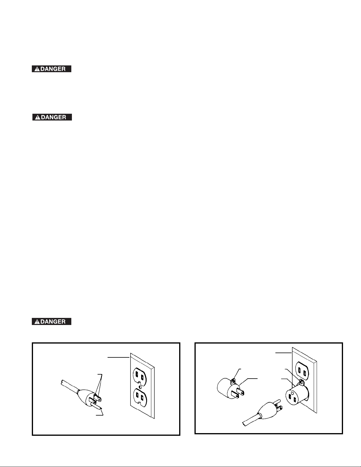
Use only 3-wire extension cords that have 3-prong grounding type plugs and matching 3-conductor receptacles that
accept the machine’ s plug, as shown in Fig. A.
Repair or replace damaged or worn cord immediately.
2. Grounded, cord-connected machines intended for use on a supply circuit having a nominal rating less than
150 volts:
If the machine is intended for use on a circuit that has an outlet that looks like the one illustrated in Fig. A, the
machine will have a grounding plug that looks like the plug illustrated in Fig. A. A temporary adapter, which looks like
the adapter illustrated in Fig. B, may be used to connect this plug to a matching 2-conductor receptacle as shown
in Fig. B if a properly grounded outlet is not available. The temporary adapter should be used only until a properly
grounded outlet can be installed by a qualified electrician. The green-colored rigid ear, lug, and the like, extending
from the adapter must be connected to a permanent ground such as a properly grounded outlet box. Whenever the
adapter is used, it must be held in place with a metal screw .
NOTE: In Canada, the use of a temporary adapter is not permitted by the Canadian Electric Code.
In all cases, make certain that the receptacle in question is properly grounded. If you are not sure,
have a qualified electrician check the receptacle.
GROUNDED OUTLET BOX
CURRENT
CARRYING
PRONGS
GROUNDING BLADE
IS LONGEST OF THE 3 BLADES
Fig. A Fig. B
GROUNDED OUTLET BOX
GROUNDING MEANS
ADAPTER
5
Page 6
EXTENSION CORDS
Use proper extension cords. Make
sure your extension cord is in good condition and is a
3-wire extension cord which has a 3-prong gr ounding
type plug and matching receptacle which will accept
the machine’s plug. When using an extension cord,
be sure to use one heavy enough to carry the current
of the machine. An undersized cord will cause a
drop in line voltage, resulting in loss of power and
overheating. Fig. D-1 shows the correct gauge to use
depending on the cord length. If in doubt, use the
next heavier gauge. The smaller the gauge number,
the heavier the cord.
FUNCTIONAL DESCRIPTION
MINIMUM GAUGE EXTENSION CORD
RECOMMENDED SIZES FOR USE WITH STATIONARY ELECTRIC MACHINES
Total
Ampere
Rating Volts
0-6 120
0-6 120 25-50 16 AWG
0-6 120 50-100 16 AWG
0-6 120 100-150 14 AWG
6-10 120
6-10 120 25-50 16 AWG
6-10 120 50-100 14 AWG
6-10 120 100-150 12 AWG
10-12 120
10-12 120 25-50 16 AWG
10-12 120 50-100 14 AWG
10-12 120 100-150 12 AWG
12-16 120
12-16 120 25-50 12 AWG
12-16 120
Length of
Cord in
Feet
up to
25 18 AWG
up to
25 18 AWG
up to
25 16 AWG
up to
GREATER THAN 50 FEET NOT RECOMMENDED
Fig. D-1
Gauge of Extension
Cord
25 14 AWG
FORWARD
Delta Model LA200 is a compact and stable wood lathe with a powerful 1/2 HP, 1725 rpm motor. This lathe will tur n
objects up to 10" in diameter over the bed and 6" in diameter over the tool rest base with a maximum distance between
centers of 37" with the optional bed extension.
NOTICE: The photo on the manual cover illustrates the current production model. All other illustrations contained in the
manual are representative only and may not depict the actual labeling or accessories included. These are intended to
illustrate technique only .
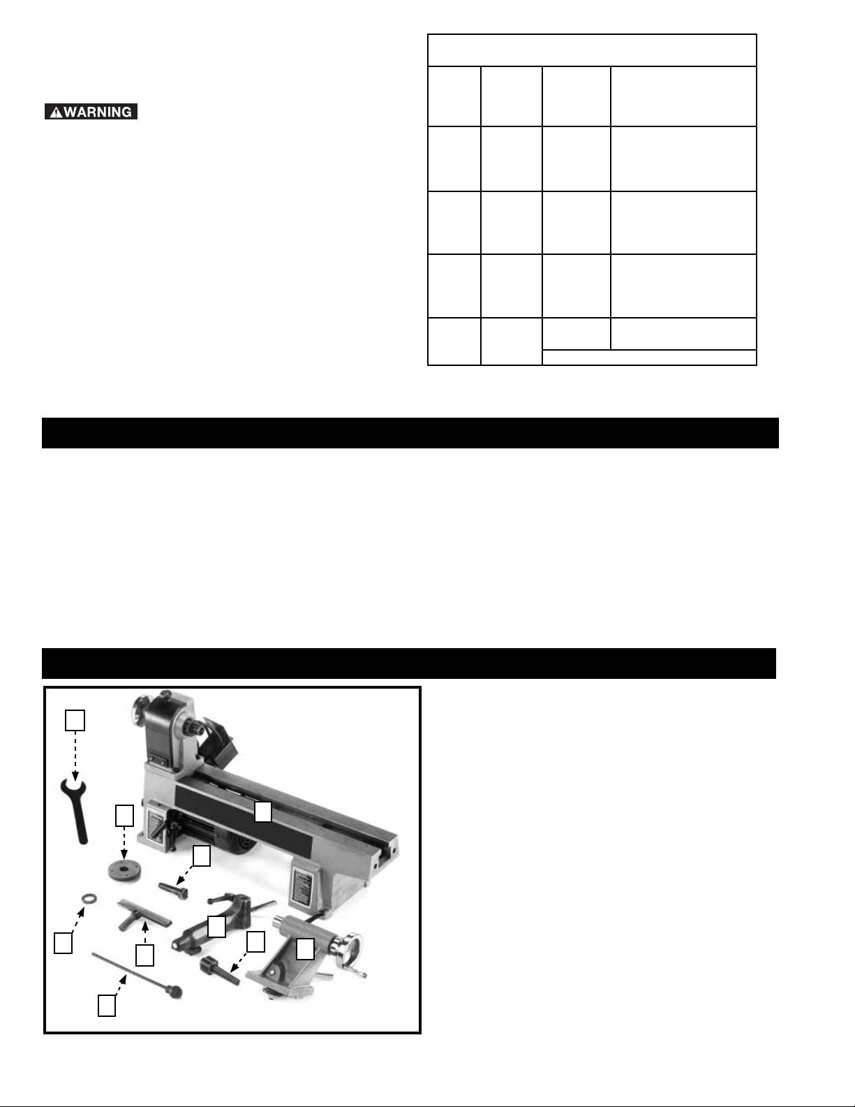
CARTON CONTENTS
10
9
1
6
1.
Lathe
2.
Tailstock
3.
Live Center
4.
Knockout Bar
5.
Tool Rest Base
6.
Spur Center
7.
Tool Rest
Spacer
5
8
7
3
2
8.
9.
10.
Face Plate
Spanner Wrench
4
6
Page 7
UNPACKING AND CLEANING
Carefully unpack the machine and all loose items from the shipping container(s). Remove the rust-preventative oil from
unpainted surfaces using a soft cloth moistened with mineral spirits, paint thinner or denatured alcohol.
Do not use highly volatile solvents such as gasoline, naphtha, acetone or lacquer thinner for cleaning your machine.
After cleaning, cover the unpainted surfaces with a good quality household floor paste wax.
ASSEMBLY
For your own safety, do not connect the machine to the power source until the machine is
completely assembled and you read and understand the entire instruction manual.
ASSEMBLY TOOLS REQUIRED
Open-end wrench (supplied)
Philips Head Screwdriver (not supplied)
ASSEMBLY TIME ESTIMATE
The assembly time for this unit is approximately 30 minutes.
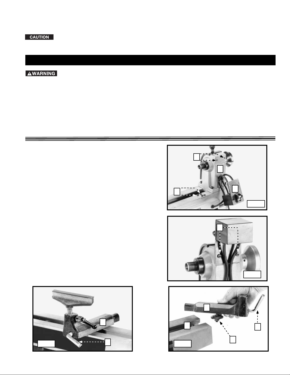
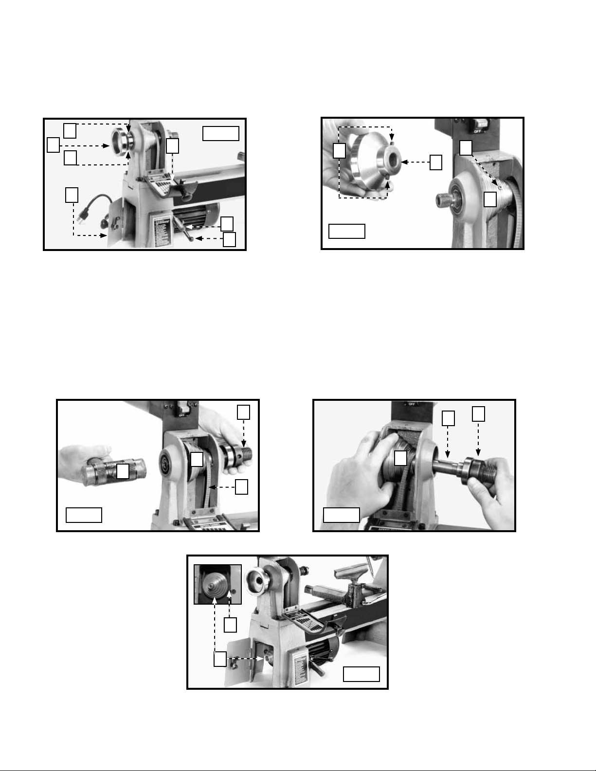
ATTACHING THE ON/OFF SWITCH
To prevent damage to the "ON/OFF" switch, the lathe
is shipped with the switch bracket detached. Attach the
switch bracket in the upright position. Align the two holes
in the switch bracket (A) Fig. 1 with the two holes (B) at
the rear of the headstock (C). Attach the switch bracket
(A) to the machine with two pan head screws (D) and
lockwashers (Fig. 2).
B
D
C
A
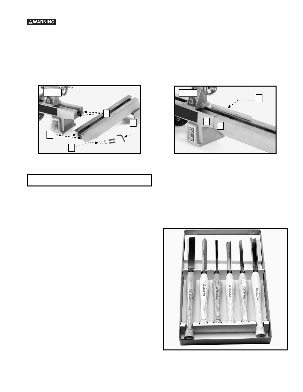
A TT ACHING THE TOOL REST TO THE LATHE BED
1. Loosen the locking lever (A) Fig. 3. Slide the tool rest
base (B) into the channel of the lathe bed (C) Fig. 4.
NOTE: If the tool rest base will not slide easily into the
channel of the lathe bed, turn the tool rest base over and
loosen the locknut (D) Fig. 3. Tighten the locking lever (A)
Fig. 4 securely.
2. IMPORTANT: If the clamping action on the tool rest
base (B) Fig. 4 is too tight or too loose on the lathe bed,
remove the base and turn the nut (D) Fig. 4 clockwise to
tighten clamping action, or counter-clockwise to loosen
the clamping action. Attach the tool rest base on the
lathe bed.
B
Fig. 3 Fig. 4
A
Fig. 1
D
Fig. 2
B
C
A
D
7
Page 8
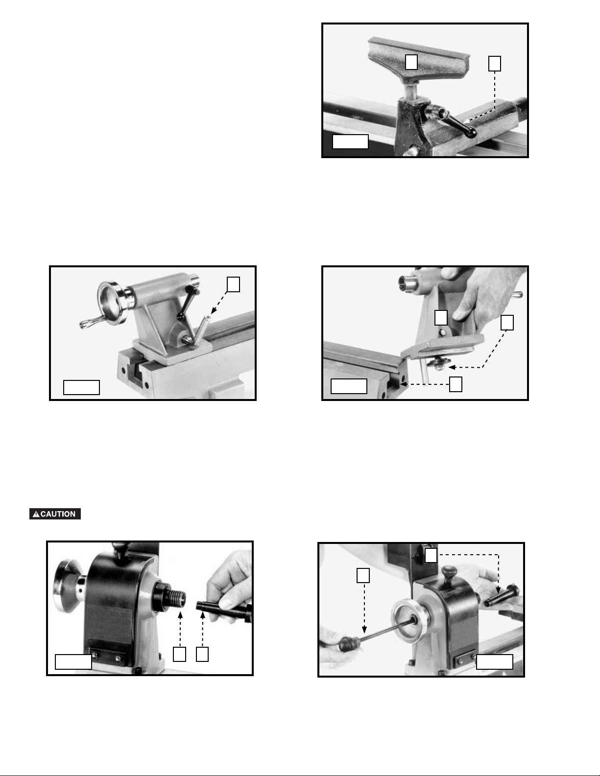
3. Loosen the locking lever (E) Fig.5 and insert the tool
rest (F) in the tool rest base.
NOTE: To adjust the height of the tool rest, loosen the
loching lever (E). After adjustment, tighten the locking
lever.
F
E
Fig. 5
A TT ACHING THE TAILSTOCK TO THE LATHE BED
1. Loosen the locking lever (A) Fig. 6, and slide the tailstock assembly (B) Fig. 7 in the channel (C) of the lathe bed.
2. IMPORTANT: If the clamping action on the tailstock (B) Fig. 7 is too tight or too loose on the lathe bed, remove the
tailstock and turn the nut (D) Fig. 7 clockwise to tighten the clamping action, or counter-clockwise to loosen the
clamping action. Attach the tailstock on the lathe bed and tighten locking lever (A) Fig. 6.
A
B
Fig. 6
ATTACHING THE HEADSTOCK SPUR CENTER TO THE LATHE
1. The supplied spur center (A) Fig. 8 is equipped with a No. 2 Morse Tapered shank (B). It will fit snugly into the headstock spindle.
NOTE: Before inserting, clean both the shank and the headstock spindle to remove grease or debris.
2. Use the knockout bar (C) Fig. 9 through the hole in the opposite end of the spindle to remove the spur center (A).
Be careful of the sharp points on the shank spur center.
Fig. 7
C
D
A
C
Fig. 8
B
A
8
Fig. 9
Page 9
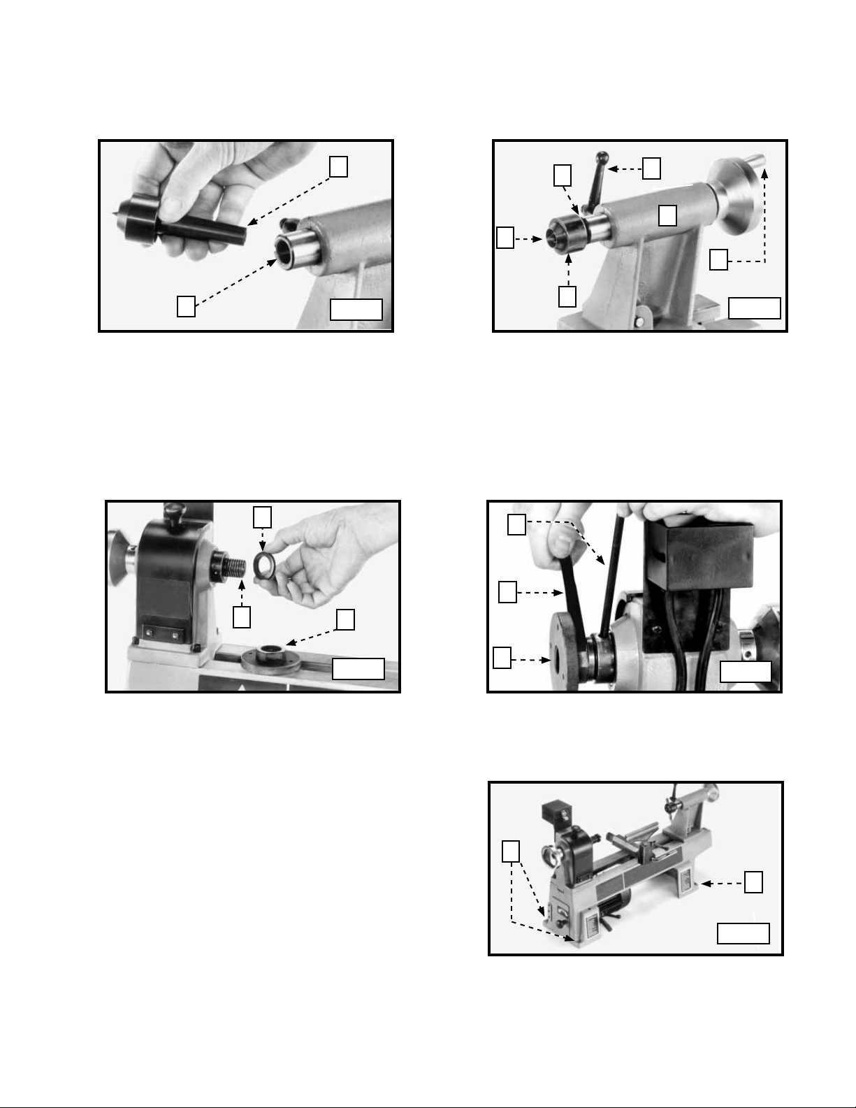
ATTACHING THE LIVE CENTER TO THE TAILSTOCK
The supplied tailstock live center (A) Fig. 10 is equipped with a No. 2 Morse Taper shank (B). This center comes inserted
in the tailstock spindle. To remove the live center (A) Fig. 11 from the tailstock spindle, loosen the lock knob (C) and rotate
the handwheel (D) to push the live center (A) out of the spindle (B). Use the knockout bar through the hollow tailstock (F) to
remove the center point (E).
B
B
C
F
E
D
A
To use the faceplate for inboard turning, mount the faceplate to the headstock spindle (shown without a workpiece for
clarity).
1. Install the spacer (A) Fig. 12 on the headstock spindle (B).
2. Thread the faceplate (C) Fig. 13 on spindle. Insert the knockout bar (D) into the hole in the spindle to keep it from turning.
Tighten the faceplate (C) with the supplied wrench (B) on the flats.
A
Fig. 10
D
A
Fig. 11
B
C
Fig. 12
FASTENING THE LATHE TO A SUPPORTING SURFACE
You must fasten the wood lathe to a supporting surface.
Four mounting holes (three of which are shown at (A) Fig.
14 are provided in the base of the lathe.
B
C
Fig. 13
A
A
Fig. 14
9
Page 10
OPERATION
OPERATIONAL CONTROLS AND ADJUSTMENTS
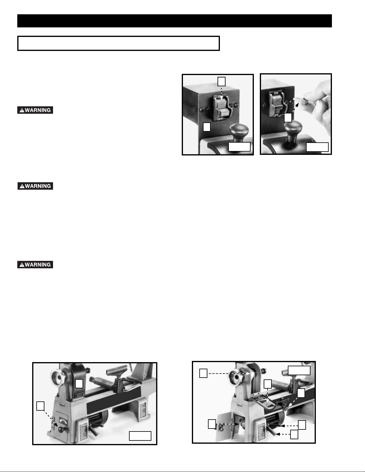
STARTING AND STOPPING THE LATHE
The on/off switch (A) Fig. 15 is located on the bracket (B)
attached earlier to the rear of the headstock. To turn the
switch “ON”, move the switch (A) up to the “ON” position.
To tur n the switch “OFF”, move the toggle switch (A) down
to the “OFF” position.
Make sure that the switch is in the “OFF”
position before plugging in the power cord. In the event
of a power failure, move the switch to the “OFF”
position. An accidental start-up can cause injury.
LOCKING THE SWITCH IN THE “OFF” POSITION
IMPORTANT: When the tool is not in use, the switch
should be locked in the “OFF” position to prevent
unauthorized use. To lock the machine, grasp the switch toggle (C) Fig. 16 and pull it out of the switch. With the switch
toggle (C) removed, the switch will not operate. However, should the switch toggle be removed while the lathe is running,
the machine can be turned “OFF,” but cannot be restarted without re-inserting the switch toggle (C).
In the event of a power outage (such as a breaker or fuse trip), always move the switch to the “OFF”
position until the main power is restored.
SPINDLE SPEEDS
This wood lathe is capable of providing speeds of 500, 800, 1250, 1800, 2650, and 3700 RPM.
CHANGING SPINDLE SPEEDS
The wood lathe features a six-step motor pulley and spindle pulley to provide the different spindle speeds for particular wood
turning applications. To change speeds:
A
C
B
Fig. 15
Fig. 16
Disconnect the machine from the power source
1. Open the doors (A) and (B) Fig. 17 to gain access to the motor pulley (C) Figs. 19 and 20, and spindle pulley (D) Figs. 18
and 20.
2. Loosen the locking lever (E) Fig. 18. Raise the lever (F) Fig. 18 and tighten the locking lever (E) to enable the drive belt to
move on the pulleys.
IMPORTANT: A speed and belt position chart (G) Figs. 18 and 20 is located on the inside of the door (A) Fig. 17 to help
position the belt correctly.
3. While holding the lever (F) Fig. 18, loosen the locking lever (E). Lower the motor.
NOTE: Push down slightly on the motor with firm finger pressure (to tension the drive belt) before you retighten the locking
lever.
4. Tighten the locking lever (E).
A
!
D
Fig. 18
G
A
B
C
Fig. 17
E
F
10
Page 11
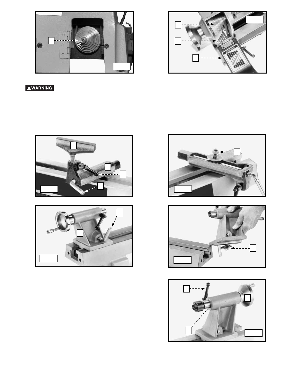
Fig. 20
D
C
C
G
Fig. 19
ADJUSTING THE TOOL REST
Disconnect the machine from the power source
For most applications, position the tool rest as close as possible to the workpiece and approximately 1/8” above the workpiece
centerline.
1. To position the tool rest base (A) Fig. 21 along the lathe bed, loosen the locking lever (B), slide the tool rest base to the
desired position, and tighten the lever (B).
2. To adjust the height of the tool rest (C) Fig. 21, loosen the lever (D), raise or lower tool rest, and tighten the lever (D).
3. You can adjust the clamping device on the tool rest base by adjusting the nut (E) clockwise to tighten or counter-clockwise
to loosen the clamping action.
!
C
E
A
D
Fig. 21 Fig. 22
B
A
B
Fig. 23
ADJUSTING THE TAILSTOCK
1. T o slide the tailstock along the lathe bed, loosen the locking
lever (A) Fig. 23. Slide the tailstock (B) into position, and
tighten the lever (A). The clamping device for the tailstock
was set prior to shipping. However, if the clamping action
needs adjustment, remove the tailstock and tighten (or
loosen) the nut (C) Fig. 24 on the bottom of the tailstock.
Re-attach the tailstock to the lathe bed.
2. To move the ram (D) Fig. 25, in or out, loosen the locking
lever (E) and turn the handwheel (F). Tighten the lever (E)
after adjusting the ram (D).
NOTE: Total ram (D) travel ranges from 0" to 1-1/2".
Fig. 24
E
C
F
D
Fig. 25
11
Page 12
REPLACING THE DRIVE BELT
1 Open the two doors (A) Fig. 26.
2. Hold the handle (B) Fig. 26, and loosen the locking lever (C). Pull up on the handle (B) to remove tension on the drive belt and
then tighten locking lever (C).
3. Loosen the two set screws (D) Figs. 26 and 27, and remove the handwheel (E).
4. Loosen the set screw (G) Fig. 27 on the spindle pulley (H).
D
E
A
D
A
Fig. 26
B
D
Fig. 27
G
E
H
C
5. Use a soft-tipped mallet (J) Fig. 28 to carefully tap the spindle shaft (K) thru the bearing. Tap it far enough to move the
spindle shaft to the right to remove the spindle pulley (H), and spindle shaft (K), (Fig. 29).
IMPORTANT: Be careful not to drop the metal key (M) Fig. 29 into the hub of the spindle pulley (H).
6. Remove the drive belt (A) Fig. 30 from the motor pulley (B).
7. Replace the drive belt and the spindle assembly in reverse order. Apply proper tension to the drive belt. Refer to section
“CHANGING SPINDLE SPEEDS”.
8. IMPORT ANT: When attaching the spindle and handwheel, tighten the the set screws in the spindle pulley against the flat
surface of the spindle. Check the spindle pulley to see if it is aligned with the motor pulley. Adjust if necessary.
K
M
K
H
J
L
Fig. 28 Fig. 29
A
B
Fig. 30
H
12
Page 13
ATTACHING THE BED EXTENSION
Disconnect the machine from the power source
The total bed length of the lathe (center to center) can be increased to 37" by purchasing and installing an accessory bed
extension. To attach the bed extension to the lathe:
1. Align the two holes in the end of the lathe bed (A) Fig. 30 with the two holes (B) in the end of bed extension. Fasten the
extension to the lathe bed with two M10 x 40 x 1-1/2" hex head screws, lockwashers, and flat washers (C) using the
supplied wrench (D).
2. IMPORTANT: Before tightening the screws, use a straight edge (E) Fig. 33 to level the lathe bed (A) with the bed
extension (B).
Fig. 30
!
Fig. 31
E
A
D
A
B
B
C
MACHINE USE
The following directions will give the inexperienced operator a beginning point for common lathe operations. Practice on
scrap material before attempting serious work.
LATHE TOOLS
Standard wood turning tools come in several different
configurations (Fig. A1). The majority of turnings will
require the gouge tool (A) Fig. A1. Use this round-nosed
hollow chisel for roughing cuts, cove cuts, and other
operations. The skew chisel (B) is a double-ground flat
chisel, with an angled end. Use this tool for smoothing
cylinders, for cutting shoulders, beads, vee-grooves, etc.
The parting tool (C) is a double-ground chisel, used for
cutting-off, or for making straight incisions or sizing cuts to
any required diameter. Use the round-nose scraper (D) for
mostly hollowing work, and the square-end scraper for the
outside of bowls.
E
CD
B
A
A
13
Fig. A1
Page 14
HOW TO TURN SPINDLES
Spindle turning is turning a workpiece attached to the lathe centers, and is used for chair and table legs, lamp stems, etc.
You can use either a scraping or cutting technique for spindles. The cutting technique, by virtue of faster wood removal and a
cleaner surface, is the preferred method.
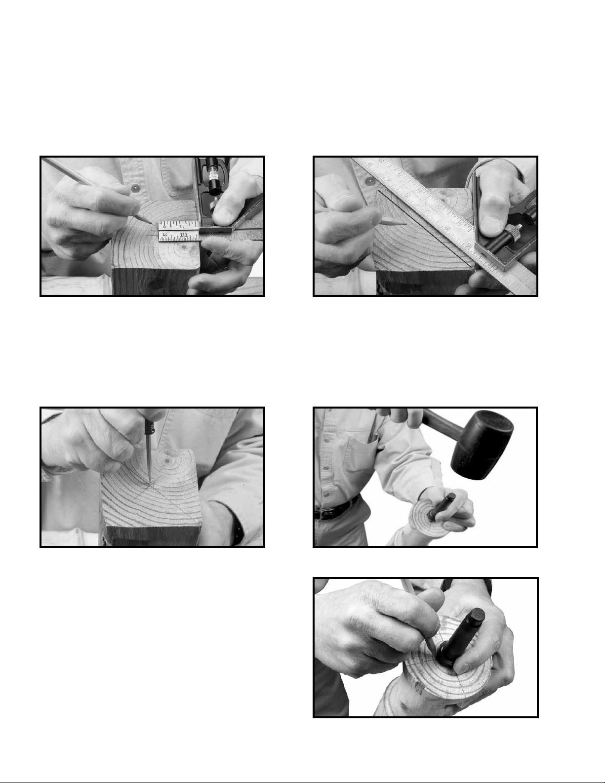
CENTERING THE WORKPIECE
Wood stock for any spindle turning should be approximately square, and the ends should be square with the sides. Two
common methods of determining the center are shown in Figs. A2 and A3. In Fig. A2, a distance a little more or a little less
than one-half the width of the stock is set off from each of the four sides. The small square set off in the center can then
be used in marking the true center. The diagonal method, Fig. A3, consists of drawing lines from corner to corner, with the
intersection marking the center of the workpiece.
Fig. A2
After marking each end, mark the true center with a punch awl or dividers (Fig. A4). If the stock is hardwood, drill the centers
to a depth of about 1/8”. Place the spur or live center against one end of the workpiece and strike it with a mallet to seat it
(Fig. A5). In hardwood, make a starting seat for the spur center by sawing on the diagonal lines, and drilling a small hole at
the intersection. After driving the center, hold the center and the workpiece together and fit both immediately to headstock
spindle. If you are not using a ball-bearing center, oil the end of workpiece at the tailstock center. Place the lubricant on the
wood either before or after it is put on the lathe. Many turners use beeswax, tallow, or a wax-and-oil mixture as a lubricant.
A ball-bearing center is ideal because it eliminates lubricating. If you plan to remove the workpiece from the lathe before
completion, make an index mark as a guide for re-centering (Fig. A6). A permanent indexer can be made by grinding off one
corner of one of the spurs.
Fig. A4
MOUNTING THE WORKPIECE
Mount the workpiece by moving the tailstock to a position
about 1" or 1-1/2" from the end of the workpiece, and
locking it in this position. Advance the tailstock center by
turning the feed handle until the center cup makes contact
with the workpiece. Do not support the workpiece on the
center pin alone. Always have the rim of the center cup
imbedded at least 1/8" into the workpiece. Continue to
advance the center while slowly rotating the workpiece
by hand. After the workpiece becomes difficult to turn,
slack off on the feed about one-quarter turn and lock the
tailstock spindle.
Fig. A3
Fig. A5
14
Fig. A6
Page 15
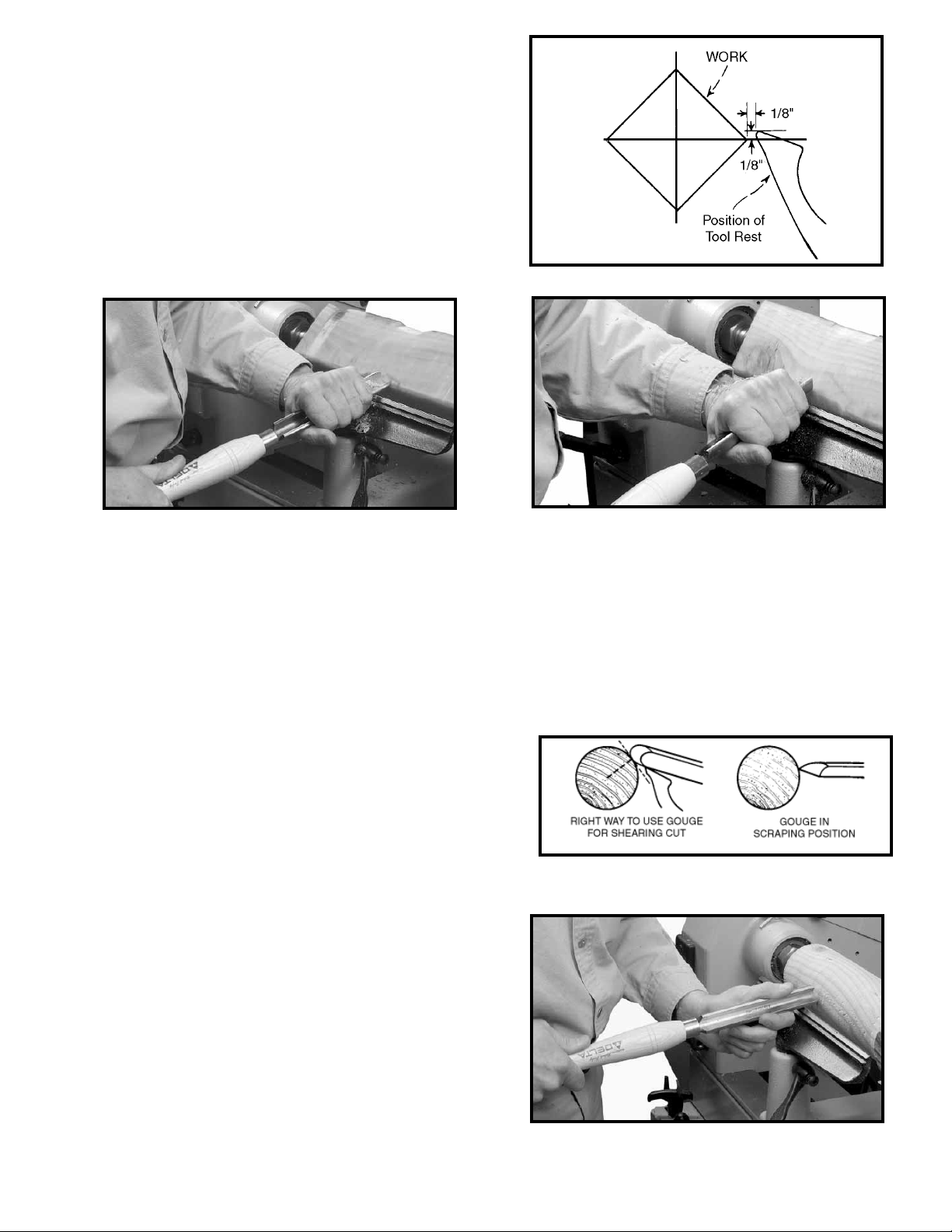
TOOL REST POSITION
Mount the tool rest in place about 1/8" away from the
work and 1/8" above the workpiece centerline (Fig. A7.)
This position may be varied to suit the workpiece and the
operator. Place a guide mark on the tool rest shank as an
aid to quick and accurate resetting.
Fig. A7
Fig. A8
ROUGHING A CYLINDER
Use the large gouge in the first turning operation to smooth the sharp corners of the workpiece. Run the lathe at low speed
and hold the gouge in the manner shown in Fig. A8. Start the cut about 2" from the tailstock end and continue to the end of the
tailstock. Make the second pass beginning about 2" or 3" to the left of the first cut. Advance again toward the tailstock, and
merge with the previous cut. Toward the end of the live center, roll the gouge in the opposite direction (Fig. A9) to carry the final
cut off the live center end of the workpiece. Do not make the roughing cut in one continuous movement. This action would tear
long slivers from the corners of the workpiece. Neither should you start the cut directly at the end of the stock. You can safely
carry the cut from the center of the stock toward and off either end once the first r oughing cuts have been made.
The position of the gouge involves two or three important angles. (1) You can advance the tool along the workpiece either from
right to left or from left to right. Left to right (from headstock to tailstock) is preferred since this action throws chips away from
you. (2) Roll the gouge over slightly in the same direction as you advance the cut. (3) Hold the tool well up on the workpiece,
with the bevel or grind tangent to the revolving surface (Fig. A10).
This position will give a clean shearing cut. When pushed straight
into the workpiece (Fig. A10), the gouge has a scraping action,
(normally a poor practice in spindle turning). Continue the roughing
cut until the workpiece approaches 1/8" of the required diameter.
Once you have a cylindrical form, you can change your turning
speed to the second or third speed setting.
NOTE: Continue to move the tool rest inward towar d the workpiece
to keep a safe distance between the two.
POSITION OF THE HANDS
Hold the tool handle in a natural position. This hand position
provides leverage for the tool by moving the chisel in or out.
The position of the tool rest hand is a matter of individual
preference, rather than a “set” or “proper” position. However,
a palm-up grip (Fig. A11) is generally considered best. In this
position, the first finger acts as a guide, sliding along the tool
rest as you make the cut.
Fig. A9
Fig. A10
15
Fig. A11
Page 16
The alternate position is a palm-down grip (Fig. A12). In this
position, the heel of the hand or the little finger serves as a guide.
The palm-down position is solid and positive – excellent for
roughing or heavy cutting. Most beginners start with the palmdown grip, switching later to the palm-up position for better
manipulation of the chisel.
SMOOTHING A CYLINDER
To smooth a cylinder, use a large skew chisel. This requires
practice, but experience with this tool is very important. Place
the cutting point near the center of chisel and high on the
workpiece (Fig. A13). Sometimes, in striving for a certain position
in relation to the workpiece, the beginner will often overlook this
all-important point. Raising the handle will increase the depth
of cut while lowering the handle does the opposite. As with the
gouge, you can advance the skew in either direction. The center
of the skew toward the heel does the actual cutting. The back
portion of the grind or bevel supports the tool, while the handle
hand controls the depth of cut by rocking the chisel on this pivot
point. Because of this, keep the skew bevel perfectly flat.
USING THE PARTING TOOL
The parting tool is perhaps the easiest turning chisel to handle.
Simply push this scraping tool into the workpiece (Fig. A14).
You will achieve a better cutting action if you hold the handle
low. In many cases, you can hold the tool with one hand while
your other hand holds the calipers in the cutting groove. When
parting tool cuts are deep, make a clearance cut alongside the
first cut (Fig. A15) to prevent burning the tool point.
Fig. A12
Fig. A13
Fig. A14
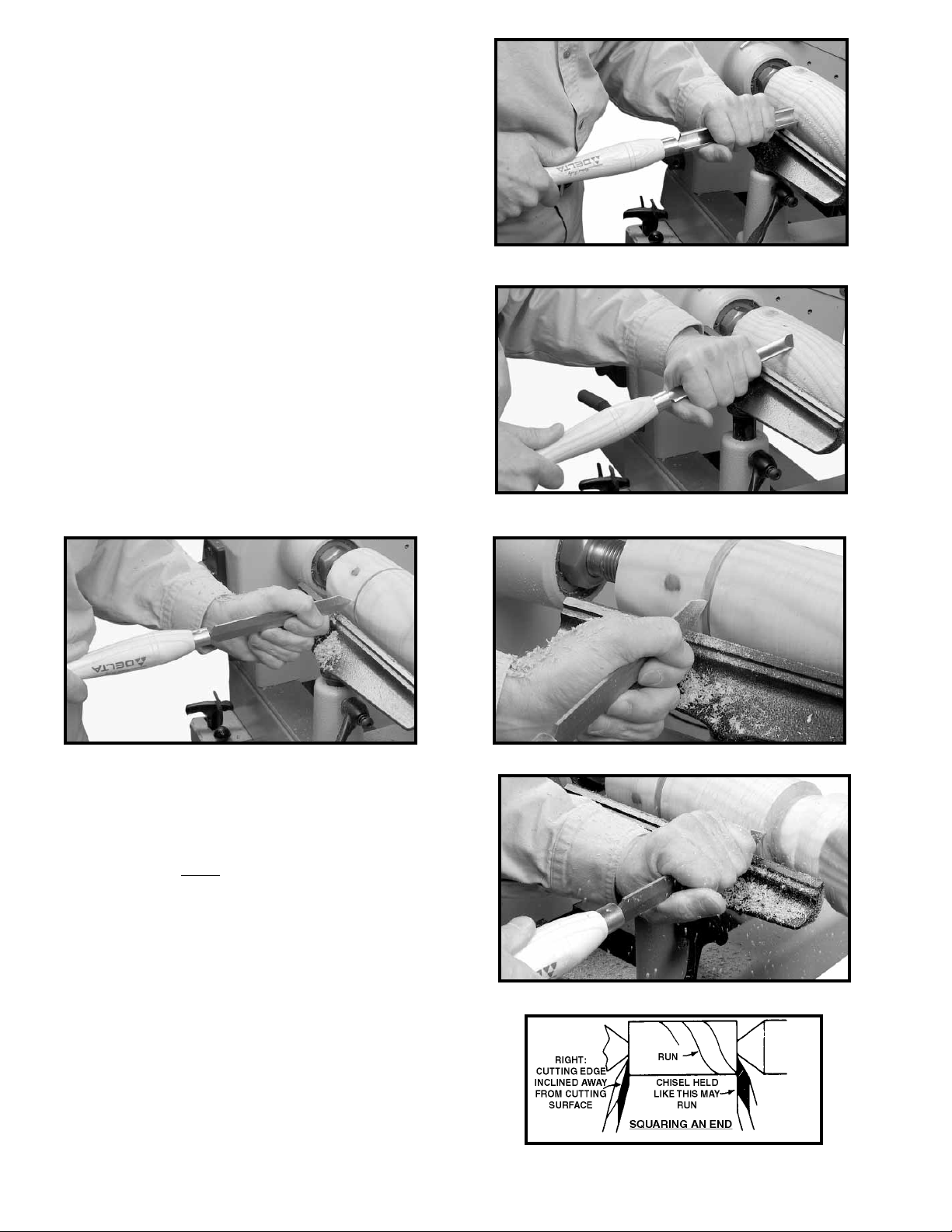
SQUARING AN END
You can use the parting tool to quickly square an end. The
parting tool is a rough cutter, but you can smooth the cut with a
skew. However, the whole operation can be done with the skew.
In using the skew, make the first nicking cut with the toe of the
skew (Fig. A16). A deep cut here could burn the chisel, so make
a clearance cut by inclining the skew away from the first cut and
pushing the tool into the workpiece. Continue this procedure of
side cut and clearance cut as often as needed.
NOTE: While the skew can be pushed into the wood in any
direction, you must incline the cutting edge a little away from
this plane. If the full cutting edge of skew bears against the cut
surface, the tool will have a tendency to run. See Fig. A17 for
the proper way to make the cut. Push the chisel straight into
the workpiece, and incline the cutting edge away from the cut
surface. Use only the extreme end of the toe for this cut. You
will use this method of skew handling repeatedly in making
shoulders, beads and vee cuts.
16
Fig. A15
Fig. A16
Fig. A17
Page 17
CUTTING A SHOULDER
Use the parting tool first to reduce the wood to within
1/16” of the required shoulder diameter (Fig. A18). Clean
the waste stock out with the gouge (Fig. A19), then use
the skew (Fig. A20) for the actual cutting of the shoulder (a
duplication of squaring an end). Use the skew to make the
horizontal cut, but in a different manner from plain cylinder
work. If the shoulder is long, use the ordinary skew position
for the outer portion of the cut. At the angle between the
horizontal and vertical cuts, move the heel of the chisel
into a position tangent between the skew and the cylinder
(Fig. A21). Raise the handle of the chisel slightly to allow it
to cut while the tool moves along the rest. Use a very light
cut to produce a smooth workpiece. You can use the heel
of the skew to make the entire cut, if desired, but, whether
in this position or any other position, do not pick up the
cut directly at the end of the stock. Horizontal cuts started
directly from the end of the workpiece will have a tendency
to bite into the wood, often ruining the entire piece. Always
run off the end and not into it. Where a very short shoulder
makes this impossible, use the skew in a flat scraping
position. If the cutting technique is used, engage only with
the heel of skew in a very light cut.
Parting tool
cuts
Fig. A18
Fig. A20
Fig. 49
Fig. A19
Fig. A21
Spear-Point
Chisel
"BEADS"
SCRAPING METHOD
Fig. A22
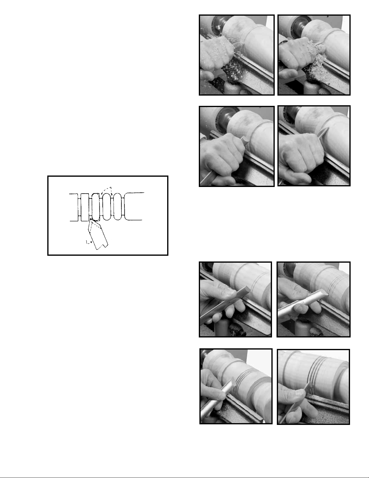
CUTTING SMALL BEADS
Beads can be scraped or cut. The spear chisel provides
the easiest method of scraping, and works well on beads
separated by parting tool cuts (Fig. A22). Scraping is
slower than cutting and is not as clean, but it has the
advantage of protecting the workpiece from long gashes.
Cutting beads quickly and accurately with the small skew
is one of the most difficult lathe operations. You can use
various working methods. One method is a vertical incision
at the point where the two curved surfaces will eventually
come together. Make this cut with either the heel or the
toe of the skew. (Fig. A23 shows the use of the toe). Place
the skew at right angles to the workpiece. Place the chisel
flat on its side at the start, and evenly rotate it through the
successive stages of the cut (Figs. A24, A25, and A26). At
the same time, pull the chisel slightly backward to maintain
the cutting point. The entire cut is made with the heel of
chisel. The opposite side of the bead is cut in the same
manner, one cut serving to produce the full shape in each
instance. This action produces beads that are beautifully
smooth and polished, and the technique is well worth
mastering.
Fig. A23
Fig. A24
17
Fig. A25
Fig. A26
Page 18
VEE GROOVES
Cutting the vee groove demands much the same technique
as the bead, except the skew is hinged straight into the
workpiece without rotation (Fig. A27). Only one-half of the
vee is made at a time, and one, two, or more cuts may be
needed on each side to obtain the desired shape. As in all
cutting with the skew, the bevel next to the cut must be
used as a fulcrum. Be careful not to allow full edge of the
chisel to catch and cause a run. You can also make Vee
grooves with the toe of the skew, in the same manner as
squaring an end.
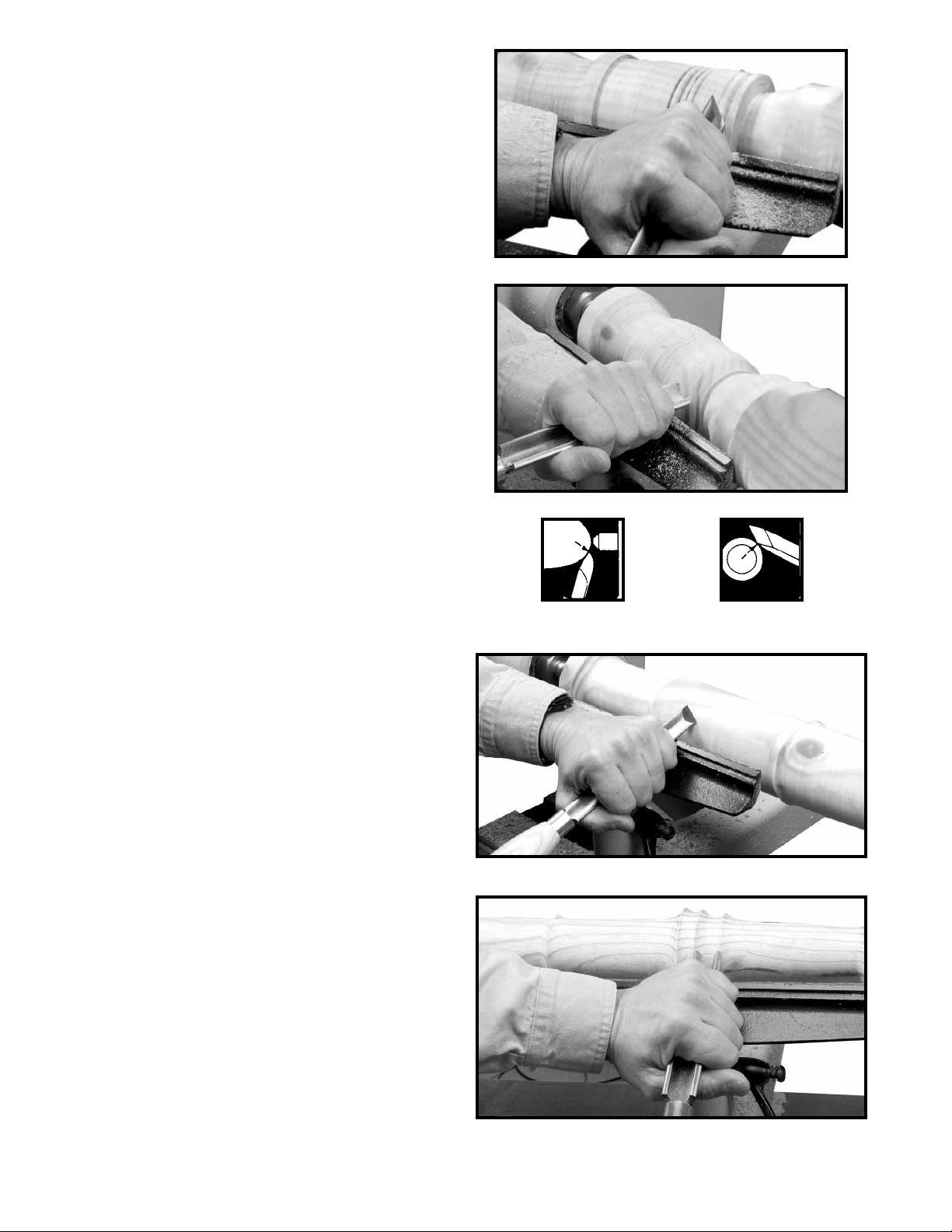
LONG CUTS
Convex or straight-tapered surfaces usually require long
cuts. With a convex surface, the method used in making
the finishing cut is shown in Fig. A28. Turn the gouge on
the tool rest so that it will be inclined toward the direction
that it will move. The grind is tangent to the workpiece, and
the center point of the cutting edge is the contact point
with the wood. As the cut progresses toward and around
the end of the curve, gradually raise the handle and swivel
it to the right (Fig. A29) to maintain the tangency between
the grind and the workpiece .
Fig. A27
Fig. A28
Figs. A30 and A31 show the cutting of a long taper with
a skew. The operation differs from smoothing a cylinder
only at the start of the cut. Make the starting cut with the
heel (Fig. A30) to prevent the tool from digging into the
workpiece. As the tool moves down the workpiece, pull the
chisel back to allow the center point of the cutting edge to
cut. However, you can make the full taper with the heel. Be
careful not to cut too deeply at the center of the taper. The
direction of cutting is always downhill.
COVE CUTS
Second to forming a perfect bead, the cove or concave
cut is the most difficult to master. Make this cut with the
gouge, where the size of the tool depends on the size of
the cut. Push the gouge directly into the workpiece to
remove the surplus stock (Fig. A32).
Fig. A29
Fig. A30
Fig. A31
18
Fig. A32
Page 19
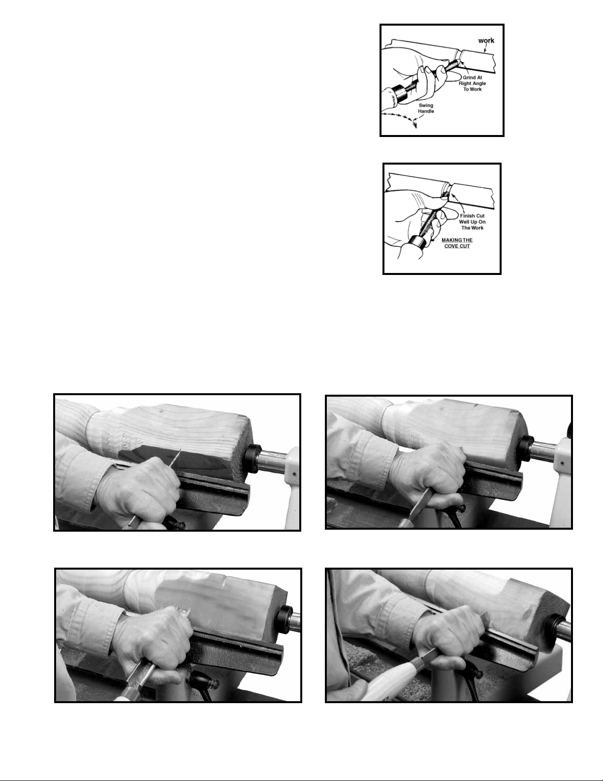
Place the gouge on the edge of the tool rest so that the
grind of the chisel forms an approximate right angle with
the workpiece (Fig. A33). Allow the chisel to contact the
workpiece at the center of the cutting edge. Hold the tool
so that the centerline of the gouge is pointing directly
toward the center of the revolving stock. This starting
position is important to prevent the gouge from running
along the surface of the workpiece.
From the starting position, push the gouge into the
workpiece and roll the tool on the rest. A triple action takes
place here. (1) Roll the chisel to follow the shape of the cut,
(2) drop the handle slightly so that the portion already cut
will force the lip of the chisel sideways and, (3) push the
chisel forward so that at the end of the cut (Fig. A34), the
chisel will be well up on the workpiece and tangent with
the cut surface. Make only one-half of the cut at a time,
then reverse the chisel to cut the other half. The occasional
turner should make cove cuts with a scraping technique,
using either the small gouge or round nose chisel.
Fig. A33
Fig. A34
Fig. A35
Fig. A37
Fig. A36
Fig. A38
19
Page 20
FACEPLATE TURNING
Mount most turnings that cannot be worked between centers on a faceplate. Some jobs require special chucks. All cutting
in faceplate work is done by scraping. Any attempt to use a cutting technique on the edge grain of large workpiece will
result in a hogging, gouging cut which may jerk the chisel out of your hands. Use a band saw on all workpiece to roughly cut
the turning area to eliminate heavy roughing cuts in turning.
MOUNTING THE WORKPIECE TO THE FACEPLATE
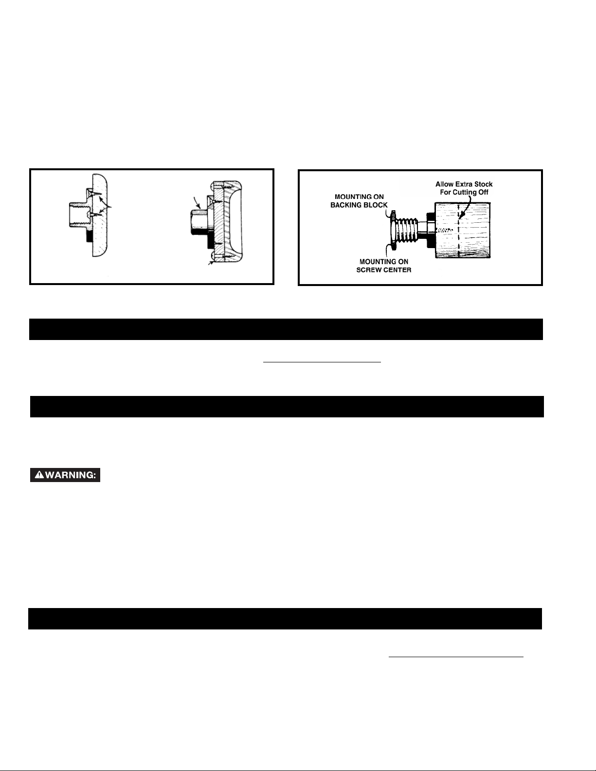
Fig. A39 shows direct mounting the workpiece to the 3" faceplate, along with attaching it to the backing block. Because of
the ease of setting up, use this mounting whenever the work permits. Hold larger pieces in the same way by using the 6"
faceplate. When normal screw-fastenings interfere, mount the workpiece on a backing block (Fig. A39). When screws are
not permissible at all, glue the workpiece to the backing block by fitting a sheet of paper at the joint to allow later separation
without damaging the wood. Some workpieces can be screwed or nailed from the face side into the backing block. Mount
workpieces less than 3” in diameter on a single screw center (Fig. A40).
8" FACEPLATE
# 8 SCREW
DIRECT MOUNTING
ON 8" FACEPLATE)
Fig. A39
BACKING BLOCK
Fig. A40
TROUBLESHOOTING
For assistance with your machine, visit our website at www.deltamachinery.com for a list of service centers or call the
DELTA Machinery help line at 1-800-223-7278 (In Canada call 1-800-463-3582).
MAINTENANCE
KEEP MACHINE CLEAN
Periodically blow out all air passages with dry compressed air. All plastic parts should be cleaned with a soft damp
cloth. NEVER use solvents to clean plastic parts. They could possibly dissolve or otherwise damage the material.
Wear certified safety equipment for eye, hearing and respiratory pr otection while using compressed air.
FAILURE TO START
Should your machine fail to start, check to make sure the prongs on the cord plug are making good contact in the
outlet. Also, check for blown fuses or open circuit breakers in the line.
LUBRICATION & RUST PROTECTION
Apply household floor paste wax to the machine table, extension table or other work surface weekly. Or use a commercially
available protective product designed for this purpose. Follow the manufacturer’s instructions for use and safety.
To clean cast iron tables of rust, you will need the following materials: a sheet of medium Scotch-Brite™ Blending Hand
Pad, a can of WD-40® and a can of degreaser. Apply the WD-40 and polish the table surface with the Scotch-Brite pad.
Degrease the table, then apply the protective product as described above.
SERVICE
REPLACEMENT PARTS
Use only identical replacement parts. For a parts list or to order parts, visit our website at
can also order parts from your nearest factory-owned branch, or by calling our Customer Care Center at 1-800-223-7278 to receive
personalized support from highly-trained technicians.
20
servicenet.deltamachinery.com.
Yo u
Page 21

FREE WARNING LABEL REPLACEMENT
If your warning labels become illegible or are missing, call
1-800-223-7278
for a free replacement.
SERVICE AND REPAIRS
All quality tools will eventually require servicing and/or replacement of parts. For information about Delta Machinery, its factoryowned branches, or an Authorized Warranty Service Center, visit our website at www.deltamachinery .com or call our Customer
Care Center at 1-800-223-7278. All repairs made by our service centers are fully guaranteed against defective material and
workmanship. We cannot guarantee repairs made or attempted by others.
You can also write to us for information at Delta Machinery, 4825 Highway 45 North, Jackson, Tennessee 38305 - Attention:
Product Service. Be sure to include all of the information shown on the nameplate of your tool (model number, type, serial number,
etc.)
ACCESSORIES
A complete line of accessories is available from your Delta Supplier, Porter-Cable • Delta Factory Service Centers, and
Delta Authorized Service Stations. Please visit our Web Site www.deltamachinery.com for a catalog or for the name of
your nearest supplier.
Since accessories other than those offered by Delta have not been tested with this product, use
of such accessories could be hazardous. For safest operation, only Delta recommended accessories should be
used with this product.
WARRANTY
To register your tool for warranty service visit our website at www.deltamachinery.com.
Two Year Limited New Product Warranty
Delta will repair or replace, at its expense and at its option, any new Delta machine, machine part, or machine accessory which in normal
use has proven to be defective in workmanship or material, provided that the customer returns the product prepaid to a Delta factory service
center or authorized service station with proof of purchase of the product within two years and provides Delta with reasonable opportunity
to verify the alleged defect by inspection. For all refurbished Delta product, the warranty period is 180 days. Delta may require that electric
motors be returned prepaid to a motor manufacturer’ s authorized station for inspection and r epair or replacement. Delta will not be responsible
for any asserted defect which has resulted from normal wear, misuse, abuse or repair or alteration made or specifically authorized by anyone
other than an authorized Delta service facility or representative. Under no circumstances will Delta be liable for incidental or consequential
damages resulting from defective products. This warranty is Delta’ s sole warranty and sets forth the customer’s exclusive remedy, with respect
to defective products; all other warranties, express or implied, whether of merchantability, fitness for purpose, or otherwise, are expressly
disclaimed by Delta.
21
Page 22

LES INSTRUCTIONS IMPORTANTES DE SURETE
d'utiliser n'importe quel outil ou n'importe quel équipement. En utilisant les outils ou l'équipement,
les précautions de sûreté fondamentales toujours devraient être suivies pour réduire le risque de
blessure personnelle. L'opération déplacée, l'entretien ou la modification d'outils ou d'équipement ont
pour résultat la blessure sérieux et les dommages de propriété. Il y a de certaines applications pour lequel outils et
l'équipement sont conçus. La Delta Machinery recommande avec force que ce produit n'ait pas modifié et/ou utilisé
pour l'application autrement que pour lequel il a été conçu.
Si vous avez n'importe quelles questions relatives à son application n'utilisent pas le produit jusqu'à ce que vous
avez écrit Delta Machinery et nous vous avons conseillé. La forme en ligne de contact à www.deltamachinery.com
Courrier Postal: Technical Service Manager, Delta Machinery, 4825 Highway 45 North, Jackson, TN 38305.
125 Mural St. Suite 300, Richmond Hill, ON, L4B 1M4.
Information en ce qui concerne l'opération sûre et correcte de cet outil est disponible des sources suivantes:
• Power Tool Institute, 1300 Sumner Avenue, Cleveland, OH 44115-2851 ou en ligne www.powertoolinstitute.org
• National Safety Council, 1121 Spring Lake Drive, Itasca, IL 60143-3201
• American National Standards Institute, 25 West 43rd Street, 4 floor, New York, NY 10036 www.ansi.org - ANSI 01.1
Safety Requirements for Woodworking Machines
• U.S. Department of Labor regulations www.osha.gov
Lire et comprendre toutes instructions d'avertissements et opération avant
Dans Canada,
MESURES DE SÉCURITÉ - DÉFINITIONS
Ce guide contient des renseignements importants que vous deviez bien saisir. Cette information porte sur VOTRE
SÉCURITÉ et sur LA PRÉVENTION DE PROBLÈMES D’ÉQUIPEMENT. Afin de vous aider à identifier cette
information, nous avons utilisé les symboles ci-dessous. Veuillez lir e attentivement ce guide en portant une attention
particulière à ces sections.
Indique un danger imminent qui, s'il n'est pas évité, causera de graves blessures ou la mort.
Indique la possibilité d’un danger qui, s’il n’est pas évité, pourrait causer de graves blessures ou
la mort
Indique la possibilité d’un danger qui, s’il n’est pas évité, peut causer des dommages à la
propriété.
S
dommages; mineures ou moyennes.
.
ans le symbole d’alerte.
Indique la possibilité d'un danger qui, s'il n'est pas évité,
peut causer des
LA PROPOSITION DE CALIFORNIE 65
activités de construction peut contenir des produits chimiques qui sont reconnus, par l'état de la Californie, de causer
le cancer, les anomalies congénitales ou autres maux de reproduction. Ces produits chimiques comprennent, entre
autres :
• le plomb provenant des peintures à base de plomb;
• la silice cristalline provenant de briques, de béton ou d'autres produits de maçonnerie
• l'arsenic et le chrome provenant du bois de charpente traité chimiquement
Le risque d'exposition à ces produits dépend de la fréquence d'exécution de ce genre de travaux. Afin de réduire l'exposition
à ces produits chimiques, travaillez dans un endroit bien aéré et utilisez de l'équipement de sécurité approuvé,
un masque facial ou respirateur homologué MSHA/NIOSH bien ajusté lorsque vous utilisez de tels outils.
La poussière produite par le ponçage électrique le sciage, le meulage, le perçage et autres
portez toujours
CONSERVEZ CES INSTRUCTIONS!
22
Page 23

RÈGLES DE SÉCURITÉ GÉNÉRALES
L ’inobservation de ces règles peut conduire à des blessures graves.
1. POUR SA SÉCURITÉ PERSONNELLE, LIRE LA NOTICE
D’UTILISATION, AVANT DE METTRE LA MACHINE EN
MARCHE, et pour aussi apprendre l’application et les limites de
la machine ainsi que les risques qui lui sont particuliers ainsi, les
possibilités d’accident et de blessures seront beaucoup réduites.
2. PORTEZ DES DISPOSITIFS DE PROTECTION DES YEUX ET DE
L'OUÏE. UTILISEZ TOUJOURS DES LUNETTES DE SÉCURITÉ.
Des lunettes ordinaires ne constituent PAS des lunettes de sécurité.
UTILISEZ DES ÉQUIPEMENTS DE SÛRETÉ HOMOLOGUÉS.
Les dispositifs de protection des yeux doivent être conformes aux
normes ANSI Z87.1. Les dispositifs de protection de l'ouïe doivent
être conformes aux normes ANSI S3.19.
3. PORTER UNE TENUE APPROPRIÉE. Pas de cravates, de gants,
ni de vêtements amples. Enlever montre, bagues et autres bijoux.
Rouler les manches. Les vêtements ou les bijoux qui se trouvent
pris dans les pièces mobiles peuvent entraîner des blessures.
4. NE PAS UTILISER LA MACHINE DANS UN ENVIRONNEMENT
DANGEREUX. L’utilisation d’outils électriques dans des endroits
humides ou sous la pluie peut entraîner des décharges électriques
ou une électrocution. Garder la zone de travail bien éclairée pour
éviter de trébucher ou d’exposer les doigts, les mains ou les bras à
une situation dangereuse.
5. GARDER LES OUTILS ET LES MACHINES EN PARFAIT ÉTAT.
Garder les outils affûtés et propres afin d’obtenir le meilleur et le
plus sûr rendement. Suivre les instructions pour lubrifier et changer
les accessoires. Les outils et les machines mal entretenus peuvent
se dégrader davantage, et/ou entraîner des blessures.
6. INSPECTER LES PIÈCES POUR DÉCELER TOUT DOMMAGE.
Avant d’utiliser la machine, la vérifier pour voir s’il n’y a pas de
pièces endommagées. Vérifier l’alignement des pièces mobiles et si
ces pièces ne se coincent pas, la rupture de pièces, ou toute autre
condition pouvant en affecter le fonctionnement. Toute pièce ou
protecteur endommagé doit être réparé ou remplacé. Les pièces
endommagées peuvent dégrader davantage la machine et/ou
entraîner des blessures.
7. GARDER L’AIRE DE TRAVAIL PROPRE. Les zones et établis
encombrés favorisent les accidents.
8. GARDER LES ENFANTS ET LES VISITEURS À DISTANCE.
L’atelier est un lieu potentiellement dangereux. Les enfants et les
visiteurs peuvent se blesser .
9. ÉVITER LE DÉMARRAGE ACCIDENTEL. S’assurer que
l’interrupteur est sur « OFF » (ARRÊT) avant de brancher le cordon.
En cas de coupure de courant, placer l’interrupteur à la position
« OFF » (ARRÊT). Un démarrage accidentel peut entraîner des
blessures.
10. UTILISER LES DISPOSITIFS PROTECTEURS. Vérifier que tous
les dispositifs protecteurs sont bien en place, bien fixés et en bon
état de marche pour éviter les blessures.
11. ENLEVER LES CLÉS DE RÉGLAGE ET CELLES DE SERRAGE
AVANT DE METTRE LA MACHINE EN MARCHE. Les outils, les
chutes et les autres débris peuvent être projetés violemment et
blesser .
12. UTILISER LA BONNE MACHINE. Ne pas forcer la machine ou
l’accessoire à faire un travail pour lequel il n’a pas été conçu. Des
dommages à la machine et/ou des blessures pourraient s’ensuivre.
13. UTILISER LES ACCESSOIRES RECOMMANDÉS. L’utilisation
d’accessoires non recommandés par Delta peut endommager la
machine et blesser l’utilisateur .
14. UTILISER LE CORDON PROLONGATEUR APPROPRIÉ.
S’assurer que le cordon prolongateur est en bon état. Lorsqu’un
cordon prolongateur est utilisé, s’assurer que celui-ci est d’un
calibre suffisant pour l’alimentation nécessaire à la machine. Un
cordon d’un calibre insuffisant entraînera une perte de tension d’où
une perte de puissance et surchauffe. V oir le tableau sur les cor dons
prolongateurs pour obtenir le calibre approprié selon la longueur du
cordon et l’ampérage de la machine. S’il y a un doute, utiliser un
cordon d’un calibre supérieur. Plus le chiffre est petit, plus le fil est
gros.
15. FIXER LA PIÈCE. Utilisez les brides ou l'étau quand vous ne
pouvez pas fixer l'objet sur la table et contre la barrière à la main ou
quand votre main sera dangereusement près de la lame (à moins de
6").
16. AVANCER LA PIÈCE DANS LE SENS CONTRAIRE À LA
ROTATION DE LA LAME, DE LA FRAISE OU DE LA SURFACE
ABRASIVE. L’alimentation dans l’autre sens peut entraîner une
projection violente de la pièce.
17. NE PAS FORCER LA MACHINE EN AVANÇANT LA PIÈCE TROP
VITE. Des dommages et/ou des blessures peuvent s’ensuivre.
18. NE PAS SE PENCHER AU-DESSUS DE LA MACHINE. Une perte
de l’équilibre peut entraîner une chute sur la machine en marche et
causer des blessures.
19. NE JAMAIS MONTER SUR LA MACHINE. On peut se blesser
gravement si la machine bascule ou si l’on touche accidentellement
son outil tranchant.
20. NE JAMAIS LAISSER LA MACHINE EN MARCHE SANS
SURVEILLANCE. COUPER LE COURANT. Ne pas quitter la
machine tant qu’elle n’est pas complètement arrêtée. Un enfant ou
un visiteur pourrait se blesser .
21. METTRE LA MACHINE À L’ARRÊT « OFF » ET LA DÉBRANCHER
avant d’installer ou d’enlever des accessoires, d’ajuster ou de
changer des montages, ou lors des réparations. Un démarrage
accidentel peut entraîner des blessures.
22. METTRE L’ATELIER À L’ABRI DES ENFANTS AU MOYEN
DE CADENAS, D’INTERRUPTEURS PRINCIPAUX OU EN
ENLEVANT LES BOUTONS DES DISPOSITIFS DE MISE EN
MARCHE. Le démarrage accidentel de la machine par un enfant ou
un visiteur peut entraîner des blessures.
23. RESTER VIGILANT, ATTENTIF, ET FAIRE PREUVE DE BON
SENS. NE PAS UTILISER LA MACHINE LORSQUE L’ON EST
FATIGUÉ OU SOUS L’INFLUENCE DE DROGUES, D’ALCOOL
OU DE MÉDICAMENTS. Un instant d’inattention lors de l’utilisation
d’outils électriques peut entraîner des blessures graves.
24.
PEUT PRODUIRE ET DISPERSER DE LA POUSSIÈRE OU
D'AUTRES PARTICULES EN SUSPENSION DANS L'AIR,
TELLES QUE LA SCIURE DE BOIS, LA POUSSIÈRE DE
SILICIUM CRISTALLIN ET LA POUSSIÈRE D'AMIANTE. Dirigez
les particules loin du visage et du corps. Faites toujours fonctionner
l'outil dans un espace bien ventilé et prévoyez l'évacuation de la
poussière. Utilisez un système de dépoussiérage chaque fois que
possible. L'exposition à la poussière peut causer des problèmes
de santé graves et permanents, respiratoires ou autres, tels que
la silicose (une maladie pulmonaire grave) et le cancer, et même le
décès de la personne affectée. Évitez de respirer de la poussière
et de rester en contact prolongé avec celle-ci. En laissant la
poussière pénétrer dans vos yeux ou votre bouche, ou en la laissant
reposer sur votre peau, vous risquez de promouvoir l'absorption de
substances toxiques. Portez toujours des dispositifs de protection
respiratoire homologués par NIOSH/OSHA, appropriés à l'exposition
à la poussière et de taille appropriée, et lavez à l'eau et au savon les
surfaces de votre corps qui ont été exposées.
L'UTILISATION DE CET OUTIL
23
Page 24

RÈGLES SPÉCIFIQUES ADDITIONNELLES DE SÛRETÉ
L ’inobservation de ces règles peut conduire à des blessures graves.
1. NE PAS F AIRE FONCTIONNER CETTE MACHINE A VANT
QU’elle ne soit assemblée et installée conformément à ces
directives.
2. DEMANDER CONSEIL à un superviseur, instructeur, ou
toute autre personne qualifiée si vous ne maîtrisez pas
parfaitement l’utilisation de cette machine.
3. SUIVRE TOUS LES CODES DE CÂBLAGE et les con-
nexions électriques recommandées.
4. DÉGROSSIR LA PIÈCE pour lui donner la forme la plus
proche de la forme finale avant de la placer sur le plateau
de montage.
5. VÉRIFIER QUE LA PIÈCE NE PRÉSENTE PAS DE
DÉFAUT et tester les joints de colle avant de monter la
pièce sur la machine. NE PAS monter une pièce fendue ou
présentant un nœud.
6. FIXER FERMEMENT LA PIÈCE au plateau de montage
avant le tournage sur plateau. Utiliser un plateau de montage de dimension appropriée pour soutenir la pièce. Les
attaches à vis ne doivent pas gêner l’outil de tournage aux
dimensions finales de la pièce.
7. NE JAMAIS DIRIGER LA PIÈCE vers la pointe
d’entraînement tant que cette dernière est dans la poupée
fixe. Insérer la pointe d’entraînement dans la pièce à l’aide
d’un maillet avant de l’installer sur la poupée fixe.
8. AJUSTER ET BLOQUER LA CONTREPOINTE contre la
pièce. Lubrifier la contrepointe si elle ne présente pas de
roulement à billes.
9. AJUSTER CORRECTEMENT LA HAUTEUR DU PORTE-
OUTIL.
10. AJUSTER LE PORTE-OUTIL de façon à ce qu’il soit aussi
près que possible de la pièce.
11. SERRER TOUTES LES POIGNÉES DE VERROUILLAGE
DES FIXATIONS avant d’utiliser l’outil.
12. TOURNER LA PIÈCE MANUELLEMENT pour vérifier le
dégagement avant de mettre la machine sous tension.
13. S’ASSURER QU’AUCUN OBJET NE SE TROUVE SUR
LE BANC DU TOUR (outils, chutes de bois, etc.) avant de
mettre la machine sous tension.
14. VÉRIFIER LE RÉGLAGE SOIGNEUSEMENT avant de
mettre la machine sous tension.
15. SE TENIR SUFFISAMMENT À L’ÉCART ET ÉLOIGNER
LES CURIEUX de la trajectoire de rotation de la pièce
afin d’éviter toute blessure due à la projection de débris.
16. UTILISER LA VITESSE LA PLUS FAIBLE lorsque vous
commencez à travailler sur une nouvelle pièce. NE
JAMAIS DÉPASSER les vitesses recommandées.
17. NE JAMAIS AJUSTER LE PORTE-OUTIL alors que la
pièce tourne.
18. NE JAMAIS DESSERRER LE FOURREAU ou la poupée
mobile alors que la pièce tourne.
19. ENGAGER LENTEMENT L’OUTIL DE COUPE DANS
LA PIÈCE, et couper de petites quantités pour le
grossissage.
20. ÔTER LE PORTE-OUTIL avant le ponçage ou le
polissage.
21. NE JAMAIS EFFECTUER D’OPÉRATIONS DE
TRAÇAGE, d’assemblage, ou de réglage sur la table/
l’espace de travail lorsque la machine est en marche.
22. ÉTEINDRE LA MACHINE ET LA DÉBRANCHER de la
source d’alimentation avant d’ajouter ou d’enlever des
accessoires, avant d’ajuster ou de modifier les réglages,
ou lors d’une réparation.
23. ÉTEINDRE LA MACHINE, la débrancher, et nettoyer
la table/l’espace de travail avant de quitter la machine.
AFIN D’ÉVITER TOUTE UTILISATION NON AUTORISÉE,
verrouiller l’interrupteur en position ARRÊT.
24. DES INFORMATIONS SUPPLÉMENTAIRES (c.-à-d.,
une vidéo sur la sécurité), indiquant comment utiliser
des outils électriques correctement et en toute sécurité,
sont disponibles auprès du Power Tool Institute, 1300
Sumner Avenue, Cleveland, OH 44115-2851, États-Unis
(www.powertoolinstitute.com). Des renseignements sont
également disponibles auprès du National Safety Council,
1121 Spring Lake Drive, Itasca, IL 60143-3201 É.-U. Se
reporter à la norme ANSI 01.1 de l’American National
Standards Institute concernant les machines de travail
du bois, ainsi que la réglementation OSHA 1910.213 du
département américain du travail.
CONSERVER CES DIRECTIVES.
Les consulter souvent et les utiliser pour donner des directives aux
autres.
24
Page 25

RACCORDEMENTS ÉLECTRIQUES
Un circuit électrique séparé doit être utilisé pour les machines. Les fils de ce circuit doivent être au moins de calibre 12. Ce
circuitdoit être protégé par un fusible temporisé de 20 A. Si on utilise un cordon prolongateur, ce cordon doit être à trois fils,
avoir unefiche à trois broches et une prise de courant à trois cavités, mise à la terre qui correspond à la fiche de la machine.
Avant debrancher la machine, s’assurer que l’interrupteur (les interrupteurs) se trouve(nt) en position « OFF » (ARRÊT) et que
le courantélectrique présente les mêmes caractéristiques que celles qui sont inscrites sur la machine. Toutes les connexions
électriquesdoivent établir un bon contact. Le fonctionnement sur une basse tension endommagera la machine.
Ne pas exposer la machine à la pluie, et ne pas l’utiliser dans des endroits humides.
SPÉCIFICATIONS DU MOTEUR
Cette machine est câblée pour un fonctionnement sur un courant alternatif de 120 volts 60 Hz. Avant de brancher la machine,
s’assurer que l’interrupteur se trouve à la position « OFF » (ARRÊT).
INSTRUCTIONS DE MISE À LA TERRE
électriques.
Cette machine doit être mise à la terre pendant son emploi, afin de protégerl’utilisateur des décharges
1. Toutes les machines avec cordon mis à la terre: Dans l’éventualité d’un mauvais fonctionnement ou d’unepanne, la
mise à la terre fournit un trajet de moindre résistancepermettant de réduire le risque de décharge électrique. Cettemachine
est dotée d’un cordon électrique possédant unconducteur de mise à la terre de l’équipement ainsi que d’unefiche mise
à la terre. La fiche doit être branchée dans une prisede courant correspondante, installée de façon adéquate etmise à la
terre conformément à tous les codes et règlementslocaux.
Ne pas modifier la fiche fournie - si elle ne s’adapte pas à laprise de courant, il faut faire installer une prise de
courantconvenable par un électricien compétent.
Un mauvais raccordement du conducteur de mise à la terrede l’équipement peut entraîner un risque de
déchargeélectrique. Le conducteur possédant un isolant avec surfaceextérieure de couleur verte, avec ou sans rayures
jaunes, estle conducteur de mise à la terre de l’équipement. Si uneréparation ou un remplacement du cordon électrique
s’avèrenécessaire, ne pas brancher le conducteur de mise à la terrede l’équipement à une borne sous tension.
Consulter un électricien compétent ou le personnel de serviceaprès-vente si on ne comprend pas entièrement
lesinstructions de mise à la terre, ou si l’on doute que la machinesoit correctement mise à la terre.
Utiliser seulement des cordons prolongateurs à trois fils dotésd’une fiche mise à la terre, à trois broches, et de prises à
troiscavités convenant à la fiche de la machine, comme l’illustre lafigure A.
Réparer ou remplacer sans délai tout cordon endommagé ouusé.
2. Machines avec cordon mis à la terre prévues pour uneutilisation sur une alimentation nominale inférieure
à150volts :Si cette machine est prévue pour être utilisée sur un circuit quicomporte une prise semblable à celle illustrée
à la figure A, lamachine devra comporter une fiche mise à la terre semblableà celle illustrée à la figureA. Un adaptateur
temporairesemblable à celui illustré à la figureB, peut être utilisé pourraccorder cette fiche à une prise à deux cavités
comme celleillustrée à la figure B, si une prise correctement mise à la terren’est pas disponible. L’adaptateur temporaire ne
doit êtreutilisé que jusqu’au moment où une prise correctement miseà la terre est installée par un électricien compétent.
L’oreillerigide ou autre dispositif semblable de couleur verte, sur ledessus de l’adaptateur, doit être connecté sur une
mise à laterre permanente comme, par exemple une boîte à prisescorrectement mise à la terre. Quand un adaptateur est
utilisé,celui-ci doit être retenu en place par une vis en métal.
REMARQUE: Au Canada, le Code canadien de l’électriciténe permet pas l’emploi d’un adaptateur temporaire.
Dans tous les cas, s'assurer quela prise en question est bien mise à la terre. Dans le doute, demander à
un électiciencompétentent de vérifier la prise.
BOÎTE À PRISES MISE À LA TERRE
BROCHES
CONDUCTRICESDE
COURANT
LA BROCHE DE MISE
ÀLA TERRE EST LA PLUS
LONGUEDES TROIS
Fig. A
BOÎTE À PRISES MISE À LA TERRE
OREILLE DE MISEÀ LA
TERRE
ADAPTATEUR
Fig. B
25
Page 26

CORDON DE RALLONGE
Employez les cordes
appropriées de prolongation. S'assurent votre corde
de prolongation est en bon état. En utilisant une corde
de prolongation, soyez sûr d'employer un assez lourd
pour porter le courant de la machine. Une corde trop
petite causera une baisse dans la tension secteur, ayant
pour résultat la perte de puissance et de surchauffe. Fig.
D-1 expositions la mesure correcte à employer selon la
longueur de corde. En cas de doute, utilisez la prochaine
mesure plus lourde. Plus le nombre de mesure est petit,
plus la corde est lourde.
DESCRIPTION FONCTIONNELLE
MESUR MINIMUM DE CORDE D’EXTENSION
TAILLES RECOMMANDÉES POUR L'CUSAGE AVEC STATIONNAIRES ÉLECTRIQUES LES OUTILS
Longueur
Estimation
pere Volts
0-6 120
0-6 120 25-50 16 AWG
0-6 120 50-100 16 AWG
0-6 120 100-150 14 AWG
6-10 120
6-10 120 25-50 16 AWG
6-10 120 50-100 14 AWG
6-10 120 100-150 12 AWG
10-12 120
10-12 120 25-50 16 AWG
10-12 120 50-100 14 AWG
10-12 120 100-150 12 AWG
12-16 120
12-16 120 25-50 12 AWG
12-16 120
Totale De
Corde En
Pieds
up to
up to
up to
up to
50 PI PLUS GRANDS QUE NON RECOMMANDES
Fig. D-1
Mesure De Corde D’Am
D’Extension
25 18 AWG
25 18 AWG
25 16 AWG
25 14 AWG
AVANT-PROPOS
Le modèle Delta LA200 est un tour à bois compact et stable doté d’un puissant moteur de 1/2 hp, 1 725 tr/min. Ce tour
permet le tournage de pièces jusqu’à 25,4 cm (10 po) de diamètre au-dessus du banc et 15,2 cm (6 po) de diamètre
au-dessus de la base du porte-outil, avec une distance maximum entre les centres de 94 cm (37 po) avec l’extension
de banc en option.
REMARQUE : La photo de la couverture du mode d’emploi illustre le modèle de production actuel. Les autres illustrations
de ce mode d’emploi ne sont présentes qu’à titre indicatif et il est possible que les étiquettes et accessoires actuels diffèrent des caractéristiques réelles de ce modèle. Ces illustrations ont uniquement pour but d’illustrer la technique.
CARTON CONTENTS
10
9
1
6
1.
Tour
2.
Poupée mobile
3.
Pointe d’entraînement
4.
Barre d’éjection
5.
Base du porte-outil
6.
Pointe à griffe
7.
Porte-outil
8.
5
8
7
3
2
10.
Cale
9.
Plateau de montage
Clé à écrous
4
26
Page 27

DÉSEMBALLAGE ET NETTOYAGE
Désemballer soigneusement la machine et toutes les pièces de ou des emballage(s) d’expédition. Retirer l’huile anticorrosion des
surfaces non peintes à l’aide d’un chiffon doux humidifié avec de l’alcool, du diluant à peinture ou de l’alcool dénaturé.
nettoyer.
Après nettoyage, couvrir les surfaces non peintes d’une cire à parquets d’usage domestique de bonne qualité.
N’utiliser pas de solvants hautement volatils tel l’essence, le naphte, l’acétone ou du diluant à laque pour
ASSEMBLAGE
soit complètement assemblée et vous lisez et comprenez le manuel d'instruction entier.
ASSEMBLAGE DE L’INTERRUPTEUR MARCHE/ARRÊT
Pour éviter que l’interrupteur MARCHE/ARRÊT ne soit
endommagé, le support de l’interrupteur n’est pas fixé sur
le tour à la livraison. Assembler le support de l’interrupteur
en position verticale. Aligner les deux trous du support de
l’interrupteur (A) fig. 1 avec les deux trous (B) situés à l’arrière
de la poupée fixe (C). Fixer le support de l’interrupteur (A) à la
machine à l’aide de deux vis à tête cylindrique à dépouille (D)
et deux rondelles de blocage (fig. 2).
Pour votre propre sûreté, ne reliez pas la machine à la source d'énergie jusqu'à ce que la machine
OUTILS NÉCESSAIRES POUR L’ASSEMBLEE
Clé à fourche (fournie)
Tournevis à tête cruciforme (non fourni)
L'ESTIMATION DE TEMPS D'ASSEMBLEE
L'assemblée pour cette machine prend approximativement 30 minutes.
B
C
D
A
FIXA TION DU PORTE-OUTIL SUR LE BANC DU TOUR
1. Desserrer le levier de blocage (A) fig. 3. Glisser la base du porteoutil (B) dans la glissière du banc du tour (C) fig. 4.
REMARQUE : Si la base du porte-outil ne glisse pas facilement
dans la glissière du banc du tour, retourner la base du porte-outil et
desserrer l’écrou de verrouillage (D) fig. 3. Serrer fermement le levier
de blocage (A) fig. 4.
2. IMPORTANT : Si l’effet de serrage de la base du porte-outil
(B) fig. 4 est trop fort ou trop faible sur le banc du tour, ôter
la base et tourner l’écrou (D) fig. 4 dans le sens des aiguilles
d’une montre pour augmenter l’effet de serrage, ou dans le
sens inverse des aiguilles d’une montre pour le réduire.
Fixer la base du porte-outil sur le banc du tour.
B
Fig. 3 Fig. 4
A
Fig. 1
D
Fig. 2
B
C
A
D
27
Page 28

3. Desserrer le levier de blocage (E) fig.5, et insérer le porteoutil (F) dans la base du porte-outil.
REMARQUE : Pour régler la hauteur du porte-outil, desserrer
le levier de blocage (E). Une fois le réglage effectué, serrer le
levier de blocage.
F
E
Fig. 5
FIXA TION DE LA POUPÉE MOBILE SUR LE BANC DU TOUR
1. Desserrer le levier de blocage (A) fig. 6, et glisser la poupée mobile (B) fig. 7 dans la glissière (C) du banc du tour.
2. IMPORTANT : Si l’effet de serrage de la poupée mobile (B) fig. 7 est trop fort ou trop faible sur le banc du tour, ôter la poupée
mobile et tourner l’écrou (D) fig. 7 dans le sens des aiguilles d’une montre pour augmenter l’effet de serrage, ou dans le sens
inverse des aiguilles d’une montre pour le réduire. Fixer la poupée mobile sur le banc du tour et serrer le levier de blocage (A)
fig. 6.
A
B
Fig. 6
FIXATION DE LA POINTE À GRIFFE DE LA POUPÉE FIXE SUR LE TOUR
1. La pointe à griffe fournie (A) fig. 8 est dotée d’une tige avec emmanchement conique Morse n° 2 (B). Elle s’insère
parfaitement dans le fourreau.
REMARQUE : Avant de l’insérer, nettoyer la tige et le fourreau afin d’enlever toute trace de graisse ou débris.
2. Faire glisser la barre d’éjection (C) fig. 9 dans le trou situé à l’opposé du fourreau pour ôter la pointe à griffe (A).
Fig. 7
C
D
Attention aux pointes de la pointe à griffe.
A
C
Fig. 8
B
A
28
Fig. 9
Page 29

FIXATION DE LA POINTE D’ENTRAÎNEMENT SUR LA POUPÉE FIXE
La pointe d’entraînement de poupée fixe fournie (A) fig. 10 est dotée d’une tige avec emmanchement conique Morse n° 2
(B). Cette pointe est insérée dans le fourreau. Pour ôter la pointe d’entraînement (A) fig. 11 du fourreau, desserrer la poignée
de verrouillage (C) et faire tourner le volant (D) pour pousser la pointe d’entraînement (A) vers l’extérieur du fourreau (B).
Faire glisser la barre d’éjection dans le creux de la poupée mobile (F) pour ôter la pointe de centrage (E).
B
B
C
F
E
D
A
Pour utiliser le plateau de montage pour un tournage intérieur, monter le plateau de montage sur le fourreau (sur la figure,
cette opération est réalisée sans pièce pour plus de clarté).
1. Fixer la cale (A) fig. 12 sur le fourreau (B).
2. Visser le plateau de montage (C) fig. 13 sur le fourreau. Insérer la barre d’éjection (D) dans le trou du fourreau pour l’empêcher
de tourner . Serrer le plateau de montage (C) sur les méplats à l’aide de la clé fournie (B).
A
Fig. 10
D
A
Fig. 11
B
C
Fig. 12
FIXATION DU TOUR À UNE SURFACE DE SUPPORT
Vous devez fixer le tour à bois à une surface de support. Le
socle du tour présente quatre trous de montage (dont trois
sont illustrés à (A) fig. 14).
B
C
Fig. 13
A
A
Fig. 14
29
Page 30

FONCTIONNEMENT
L'OPERATION CONTROLE DE LE ET LES AJUSTEMENTS
DÉMARRAGE ET ARRÊT DU TOUR
A
L’interrupteur marche/arrêt (A) fig. 15 est situé sur le support
(B) assemblé précédemment à l’arrière de la poupée fixe. Pour
allumer l’interrupteur, déplacer le bouton de l’interrupteur (A)
en position « MARCHE » (ON). Pour éteindre l’interrupteur,
déplacer l’interrupteur à bascule (A) vers le bas, en position «
ARRÊT » (OFF).
se trouve sur la position d’arrêt avant de brancher le
S’assurer que l’interrupteur
cordon d’alimentation. En cas de panne de courant,
mettre l’interrupteur sur la position d’arrêt. Un démarrage
accidentel peut provoquer des blessures.
VERROUILLAGE DE L’INTERRUPTEUR EN POSITION D’ARRÊT
IMPORTANT : lorsque l’outil est inutilisé, l’interrupteur doit être verrouillé en position d’arrêt afin d’empêcher toute
utilisation non autorisée. Pour verrouiller la machine, saisir la bascule de l’interrupteur (C) fig. 16 et la retirer de l’interrupteur.
Une fois la bascule de l’interrupteur (C) retirée, l’interrupteur ne fonctionnera pas. Cependant, si la bascule de l’interrupteur est
retirée tandis que le tour est en marche, il sera possible d’éteindre l’outil mais pas de le redémarrer sans réinsérer la bascule de
l’interrupteur (C).
En cas de panne d’électricité (disjoncteur désarmé ou un fusible grillé), toujours déplacer
l’interrupteur en position d’arrêt (off) jusqu’à ce que l’alimentation soit rétablie.
VITESSES DE BROCHE
Ce tour à bois peut fournir des vitesses de 500, 800, 1 250, 1 800, 2 650, et 3 700 tr/min.
B
Fig. 15
C
Fig. 16
MODIFICATION DES VITESSES DE BROCHE
Ce tour à bois dispose d’une poulie de moteur et d’une poulie de broche à six positions pour permettre différentes vitesses de
broche selon les applications de tournage du bois. Pour modifier la vitesse :
Débrancher la machine de la source de pouvoir.
1. Ouvrir les portes (A) et (B) fig. 17 pour accéder à la poulie du moteur (C) fig. 19 et 20 et à la poulie de la broche (D) fig. 18 et
20.
2. Desserrer le levier de blocage (E) fig. 18. Soulever le levier (F) fig. 18 et serrer le levier de blocage (E) pour permettre à la
courroie d’entraînement de se déplacer sur les poulies.
IMPORTANT : Vous trouverez un tableau des vitesses et de positionnement de la courroie (G) fig. 18 et 20 sur la face
interne de la porte (A) fig. 17 pour vous aider à positionner la courroie correctement.
3. Tout en tenant le levier (F) fig. 18, desserrer le levier de blocage (E). Abaisser le moteur.
REMARQUE : Appliquer une légère pression du doigt sur le moteur (pour tendre la courroie d’entraînement) avant de resserrer
le levier de blocage.
4. Serrer le levier de blocage (E).
D
A
G
Fig. 18
A
B
Fig. 17
30
C
E
F
Page 31

Fig. 20
D
C
G
Fig. 19
RÉGLAGE DU PORTE-OUTIL
Débrancher la machine de la source de pouvoir.
Pour la plupart des applications, positionner le porte-outil aussi près que possible de la pièce, et environ 3,2 mm (1/8 po) au-dessus du
centre de la pièce.
1. Pour positionner la base du porte-outil (A) fig. 21 le long du banc du tour, desserrer le levier de blocage (B), glisser la base du porteoutil à l’emplacement désiré, et serrer le levier (B).
2. Pour régler la hauteur du porte-outil (C) fig. 21, desserrer le levier (D), lever ou abaisser le porte-outil, et serrer le levier (D).
3. Vous pouvez régler le dispositif de serrage sur la base du porte-outil en ajustant l’écrou (E) dans le sens des aiguilles d’une montre
pour augmenter l’effet de serrage, ou dans le sens inverse des aiguilles d’une montre pour le réduire.
C
E
A
D
Fig. 21
B
A
B
Fig. 23
RÉGLAGE DE LA POUPÉE MOBILE
1. Pour glisser la poupée mobile le long du banc du tour,
desserrer le levier de blocage (A) fig. 23. Glisser la poupée
mobile (B) en position, et serrer le levier (A). Le dispositif
de serrage de la poupée mobile a été réglé en usine.
Toutefois, s’il est nécessaire de régler l’effet de serrage,
ôter la poupée mobile et serrer (ou desserrer) l’écrou (C) fig.
24 qui se trouve sur la partie inférieure de la poupée mobile.
Fixer à nouveau la poupée mobile au banc du tour.
Fig. 22
C
Fig. 24
E
F
2. Pour déplacer le fourreau (D) fig. 25 vers l’intérieur ou vers
l’extérieur, desserrer le levier de blocage (E) et tourner le
volant (F). Serrer le levier (E) après avoir ajusté le fourreau
(D).
REMARQUE : La course totale du fourreau (D) varie entre 0 mm
et 38 mm (1 1/2 po).
D
Fig. 25
Page 32

REMPLACEMENT DE LA COURROIE D’ENTRAÎNEMENT
1 Ouvrir les deux portes (A) fig. 26.
2. Tenir la poignée (B) fig. 26, et desserrer le levier de blocage (C). Tirer sur la poignée (B) pour r elâcher la tension de la courr oie et
serrer le levier de blocage (C).
3. Desserrer les deux vis de calage (D) fig. 26 et 27, et retirer le volant (E).
4. Desserrer la vis de calage (G) fig. 27 qui se trouve sur la poulie de la broche (H).
D
E
A
D
Fig. 26
G
D
E
A
H
B
C
5. Utiliser un maillet-caoutchouc (J) fig. 28 pour enfoncer doucement l’arbre de la broche (K) dans le roulement. L’enfoncer assez
profond pour déplacer l’arbre de la broche vers la droite de façon à retirer la poulie de la broche (H), et l’arbre de la broche (K)
fig. 29.
IMPORTANT : Attention à ne pas faire tomber la clé en métal (M) fig. 29 dans le moyeu de la poulie de la broche (H).
6. Retirer la courroie d’entraînement (A) fig. 30 de la poulie du moteur (B).
7. Remonter la courroie d’entraînement et la broche en effectuant l’inverse de la procédure décrite ci-dessus. Ajuster
correctement la tension de la courroie d’entraînement. Consulter la section « MODIFICATION DES VITESSES DE BROCHE ».
8. IMPORTANT : Lors de l’assemblage de la broche et du volant, serrer les vis de calage de la poulie de la broche contre la
surface plane de la broche. Vérifier que la poulie de la broche est alignée à la poulie du moteur. Régler le cas échéant.
Fig. 27
K
H
J
L
Fig. 28 Fig. 29
A
B
Fig. 30
M
K
H
32
Page 33

FIXATION DE L’EXTENSION DE BANC
Débrancher la machine de la source de pouvoir.
La longueur totale du banc du tour (centre à centre) peut être augmentée jusqu’à 94 cm (37 po) en achetant et en installant
une extension de banc accessoire. Pour fixer l’extension de banc au tour:
1. Aligner les deux trous qui se trouvent à l’extrémité du banc du tour (A) fig. 30 avec les deux trous (B) qui se trouvent à
l’extrémité de l’extension de banc. Fixer l’extension au banc du tour avec deux vis à tête hexagonale M10 x 40 x 38 mm
( M10 x 40 x 1 1/2 po), deux rondelles de blocage et deux rondelles plates (C) à l’aide de la clé fournie (D).
2. IMPORTANT : Avant de serrer les vis, utiliser une règle droite (E) fig. 33 pour mettre à niveau le banc du tour (A) avec
l’extension de banc (B).
Fig. 30
Fig. 31
E
A
D
A
B
B
C
UTILISATION DE LA MACHINE
Les directives suivantes donneront à l’opérateur sans expérience une idée des principales opérations de tournage. Effectuer
des essais sur des déchets de découpe avant de réaliser le tournage de la pièce.
OUTILS DE TOURNAGE
Les outils standard de tournage du bois existent
en différentes configurations (fig. A1). La plupart des
tournages nécessitent l’utilisation d’une gouge (A) fig. A1.
Utiliser ce bédane creux à bout rond pour le dégrossissage,
les coupes de gorges, et d’autres opérations. Le ciseau à
épauler (B) est un burin à bout plat à double meulage dont
l’extrémité est biseautée. Utiliser cet outil pour lisser les
cylindres, réaliser des épaulements, des baguettes, des
rainures en V, etc. Le ciseau à couper (C) est un ciseau à
double meulage qui est utilisé pour tronçonner, ou pour
réaliser des incisions droites ou mettre à dimension une
pièce à un diamètre donné. Utiliser principalement le
grattoir à bout rond (D) pour les ouvrages de mortaisage et
le grattoir à bout droit pour l’extérieur des bols.
33
E
CD
B
A
Fig. A1
A
Page 34

COMMENT RÉALISER UN TOURNAGE ENTRE POINTES
Le tournage entre pointes consiste à tourner une pièce fixée aux pointes du tour et est utilisé pour les chaises et les pieds de table,
les tiges de lampe, etc. Vous pouvez utiliser une technique de raclage ou de coupe pour le tournage entre pointes. La technique de
coupe est la méthode la plus prisée, car elle permet de couper le bois plus rapidement et offre une surface plus nette.
CENTRAGE DE LA PIÈCE
Pour un tournage entre pointes, la pièce de bois doit avoir une forme relativement carrée, et ses extrémités doivent être à angle
droit avec les côtés. Deux méthodes couramment utilisées pour déterminer le centre sont illustrées par les fig. A2 et A3. Pour la
fig. A2, une distance plus ou moins égale à la moitié de la largeur de la pièce de bois est déterminée à partir de chacun des quatre
côtés. Ce petit carré déterminé au centre peut alors être utilisé pour marquer le centre réel. La méthode des diagonales, fig. A3,
consiste à tracer des lignes d’un coin à l’autre pour déterminer le centre de la pièce grâce au point d’intersection de ces lignes.
Fig. A2
Après avoir marqué chaque extrémité, marquer le centre réel à l’aide d’un poinçon ou d’un compas (fig. A4). Si la pièce est en bois
dur, percer le centre jusqu’à environ 3,2 mm (1/8 po) de profondeur. Placer la pointe à griffe ou la pointe d’entraînement contre l’une
des extrémités de la pièce et la frapper à l’aide d’un maillet pour l’enfoncer (fig. A5). Si la pièce est en bois dur, faire une première
marque pour la pointe à griffe en perçant un petit trou à l’intersection des diagonales. Après avoir vissé la pointe, maintenir la pointe
et la pièce ensemble et les fixer immédiatement à la broche de la poupée fixe. Si vous n’utilisez pas une pointe à roulement à billes,
lubrifier l’extrémité de la pièce au niveau de la contrepointe. Appliquer le lubrifiant sur le bois avant ou après avoir placé la pièce sur
le tour. De nombreux tourneurs utilisent de la cire d’abeilles, du suif, ou une mixture à base de cire et d’huile en guise de lubrifiant.
L’utilisation d’une pointe à roulement à billes est idéale car il n’est alors pas nécessaire de lubrifier. Si vous prévoyez de retirer la
pièce du tour avant d’avoir terminé votre ouvrage, effectuez une marque pour vous aider à centrer la pièce à nouveau (fig. A6). Il est
possible d’effectuer une marque permanente en meulant un des coins de l’une des griffes.
Fig. A4
MONTAGE DE LA PIÈCE
Fig. A3
Fig. A5
Monter la pièce en déplaçant la poupée mobile à une position
d’environ 25 mm (1 po) ou 38 mm (1 1/2 po) à partir de
l’extrémité de la pièce, et en la bloquant dans cette position.
Avancer la contrepointe en tournant la poignée d’avance
jusqu’à ce que la pointe soit en contact avec la pièce. Ne
pas maintenir la pièce seulement sur la broche centrale. Le
bord de la pointe doit toujours être enfoncé d’au moins 3,2
mm (1/8 po) dans la pièce. Continuer à avancer la pointe tout
en faisant lentement tourner la pièce manuellement. Une fois
qu’il devient difficile de tourner la pièce, relâcher l’avance
d’environ un quart de tour et bloquer le fourreau.
Fig. A6
34
Page 35

POSITION DU PORTE-OUTIL
Fixer le porte-outil en place à environ 3,2 mm (1/8 po)
de la pièce et 3,2 mm (1/8 po) au-dessus du centre de la
pièce (fig. A7). Cette position peut varier selon la pièce
et l’opérateur. Placer une marque de guide sur la tige du
porte-outil pour vous permettre de repositionner la pièce
rapidement et avec précision.
PIÈCE
POSITION
DU PORTE-OUTIL
Fig. A7
Fig. A8
Fig. A9
DÉGROSSISSAGE D’UN CYLINDRE
Utiliser la grande gouge pour la première phase du tournage afin de lisser les coins tranchants de la pièce. Utiliser le tour à faible
vitesse et tenir la gouge comme indiqué sur la fig. A8. Commencer la coupe à environ 50 mm (2 po) de l’extrémité de la poupée
mobile et continuer jusqu’à l’extrémité de la poupée mobile. Effectuer la seconde coupe en commençant à environ 50,8 mm ou 76,2
mm (2 po ou 3 po) à gauche de la première coupe. Avancer à nouveau vers la poupée mobile, jusqu’à rejoindre la coupe précédente.
Faire rouler la gouge dans l’autre sens vers l’extrémité de la pointe d’entraînement (fig. A9) pour effectuer la coupe finale jusqu’à
l’extrémité de la pointe d’entraînement de la pièce. Ne pas dégrossir d’un seul mouvement continu. En effet, de longs éclats de bois
pourraient se détacher des coins de la pièce. Ne pas commencer la coupe directement par l’extrémité de la pièce. Vous pouvez
réaliser la coupe en toute sécurité du centre de la pièce vers l’une de ses extrémités, une fois que le dégrossissage a été effectué.
La position de la gouge implique deux ou trois angles importants. (1) Vous pouvez avancer l’outil le long de la pièce de gauche à
droite ou de droite à gauche. Il est recommandé d’avancer l’outil de gauche à droite (de la poupée fixe à la poupée mobile) pour
que les copeaux ne soient pas projetés dans votre direction. (2) Faire rouler la gouge légèrement dans la même direction alors
que vous faites progresser la coupe. (3) Bien tenir l’outil au-dessus de la pièce, le biseau ou la pointe de meulage tangent(e) à la
surface tournante (fig. A10). Cette position permet une coupe nette.
Lorsqu’elle est avancée tout droit dans la pièce (fig. A10), la gouge a
pour effet de racler (ce qui constitue une pratique médiocre pour le
tournage entre pointes). Continuer le dégrossissage jusqu’à ce que la
pièce ne soit plus qu’à 3,2 mm (1/8) du diamètre désiré. Lorsque vous
avez obtenu une forme cylindrique, vous pouvez changer de vitesse
de tournage pour passer à la deuxième ou troisième vitesse.
FAÇON CORRECTE D’UTILISER LA
GOUGE POUR UNE COUPE PRÉCISE
GOUGE EN POSITION
DE RACLAGE
REMARQUE : Continuer à déplacer le porte-outil vers l’intérieur en
direction de la pièce pour conserver une distance de sécurité entre
les deux.
Fig. A10
POSITION DES MAINS
Tenir le manche de l’outil de façon naturelle. Cette position
des mains permet d’utiliser l’outil avec efficacité en
déplaçant le ciseau vers l’intérieur ou vers l’extérieur. La
position de la main qui se trouve sur le porte-outil dépend
des préférences de chacun, et n’obéit pas à des règles
particulières. Toutefois, il est souvent préférable de tenir le
porte-outil paume vers le haut (fig. A11). Dans cette position,
l’index sert de guide en glissant le long du porte-outil à
mesure que vous réalisez la coupe.
35
Fig. A11
Page 36

Il est également possible de tenir le porte-outil paume vers le bas (fig. A12). Dans cette position, c’est la paume de la main ou
l’auriculaire qui sert de guide. La position paume vers le bas permet une bonne prise, idéale pour le dégrossissage ou pour couper les
pièces épaisses. La plupart des débutants commencent par tenir le porte-outil paume vers le bas, puis finissent par utiliser la position
paume vers le haut pour une meilleure manipulation du ciseau.
LISSAGE D’UN CYLINDRE
Pour lisser un cylindre, utiliser un grand ciseau à épauler. Cette opération exige une grande pratique, mais il est très important de
s’entraîner avec cet outil. Placer la pointe coupante près du centre du ciseau et haut sur la pièce (fig. A13). Parfois, en essayant
tant bien que mal de trouver la bonne position par rapport à la pièce, les débutants en oublient ce point très important. Lever le
manche aura pour effet d’augmenter la profondeur de la coupe, tandis qu’abaisser le manche produira l’effet inverse. Concernant la
gouge, vous pouvez avancer le ciseau à épauler dans l’une ou l’autre direction. La coupe s’effectue en dirigeant le centre du ciseau
à épauler vers le talon. La partie arrière de la pointe de meulage ou du biseau soutient l’outil, tandis que la main qui se trouve sur le
manche contrôle la profondeur de coupe en balançant le ciseau sur son point de pivotement. De ce fait, s’assurer que le biseau du
ciseau à épauler est parfaitement plat.
UTILISATION DU CISEAU À COUPER
Le ciseau à couper est peut-être le ciseau de tournage le plus facile à manipuler. Il suffit d’avancer cet outil de raclage dans la
pièce (fig. A14). L’action de coupe sera meilleure en tenant le manche assez bas. Dans de nombreuses situations, il est possible de
tenir l’outil à une main tandis que l’autre main tient le compas dans la rainure de la coupe. Lorsque les coupes réalisées à l’aide du
ciseau à couper sont profondes, effectuer une coupe de dégagement le long de la première coupe (fig. A15) pour éviter de brûler la
pointe de l’outil.
Fig. A12 Fig. A13
Fig. A14
ÉQUARRISSAGE D’UNE EXTRÉMITÉ
Il est possible d’utiliser le ciseau à couper pour équarrir
rapidement une extrémité. Le ciseau à couper effectue des
coupes grossières, mais il est possible de lisser la coupe à
l’aide d’un ciseau à épauler. Il faut noter que l’intégralité de
l’opération peut être effectuée à l’aide du ciseau à épauler.
Lors de l’utilisation du ciseau à épauler, effectuer la première
entaille avec le bout du ciseau (fig. A16). Une coupe profonde
pourrait brûler le ciseau, par conséquent il est nécessaire de
réaliser une coupe de dégagement en inclinant le ciseau à
l’écart de la première coupe et en enfonçant l’outil dans la
pièce. Réaliser cette procédure de coupe latérale et de coupe
de dégagement aussi souvent que nécessaire.
REMARQUE : Bien que le ciseau à épauler puisse être
enfoncé dans le bois dans toutes les directions, le bord
coupant doit être incliné un peu en retrait de ce plan. Si le
bord coupant est complètement appuyé contre la surface
coupée, l’outil aura tendance à déraper. Voir la (fig. A17) pour
savoir comment réaliser la coupe correctement. Enfoncer le
ciseau tout droit dans la pièce, et incliner le bord coupant
de façon à l’éloigner de la surface coupée. N’utiliser que la
pointe du bout du ciseau pour cette coupe. Cette méthode de
manipulation du ciseau à épauler sera fréquemment utilisée
pour réaliser des épaulements, des baguettes et des rainures
en V.
Fig. A15
Fig. A16
MÉTHODE
CORRECTE :
BORD COUPANT
INCLINÉ DE FAÇON
À S’ÉLOIGNER
DE LA SURFACE
À COUPER
Fig. A17
DÉRAPAGE
TENU AINSI, LE
CISEAU PEUT
DÉRAPER
ÉQUARRIR UNE EXTRÉMITÉ
36
Page 37

RÉALISER UN ÉPAULEMENT
Utiliser d’abord le ciseau à couper pour que la pièce ne
soit plus qu’à 1,6 mm (1/16 po) du diamètre souhaité pour
l’épaulement (fig. A18). Enlever les chutes de bois à l’aide
de la gouge (fig. A19), puis utiliser le ciseau à épauler (fig.
A20) pour réaliser la coupe de l’épaulement (opération
identique à l’équarrissage d’une extrémité). Utiliser le ciseau à
épauler pour réaliser la coupe horizontale, mais différemment
d’un simple ouvrage sur cylindre. Si l’épaulement est long,
utiliser le ciseau à épauler en position ordinaire pour la partie
extérieure de la coupe. À un angle qui se situe entre la coupe
horizontale et la coupe verticale, déplacer le talon du ciseau
selon une position tangente entre le ciseau à épauler et le
cylindre (fig. A21). Lever le manche du ciseau doucement
pour lui permettre de couper pendant que l’outil se déplace
le long du porte-outil. Réaliser une coupe très légère pour
produire une pièce lisse. Vous pouvez utiliser le talon du
ciseau à épauler pour réaliser la coupe dans son intégralité si
vous le souhaitez, cependant, qu’il s’agisse de cette position
ou de toute autre position, vous ne devez pas commencer
la coupe directement à l’extrémité de la pièce. Les coupes
horizontales réalisées directement depuis l’extrémité de la
pièce auront tendance à « mordre » le bois, ruinant ainsi
souvent la pièce tout entière. Toujours procéder de l’intérieur
vers l’extrémité, et non pas de l’extrémité vers l’intérieur.
Lorsqu’un épaulement très petit le permet, utiliser le ciseau
à épauler dans une position de raclage à plat. Si la technique
de coupe est utilisée, n’utiliser que le talon du ciseau pour
une coupe très légère.
Fig. A18
Fig. 49
Fig. A19
Coupes réalisées avec
le ciseau à couper
MÉTHODE DE RACLAGE
Ciseau
à pointe javelot
POUR RÉALISER DES
BAGUETTES
Fig. A22
COUPE DE PETITES BAGUETTES
Il est possible de racler ou de couper de petites baguettes.
Le ciseau à pointe javelot offre la méthode de raclage la plus
simple, et fonctionne bien sur les baguettes séparées par des
coupes réalisées au ciseau à couper (fig. A22). Le raclage est
plus lent que la coupe et n’est pas aussi net, mais il présente
l’avantage de protéger la pièce contre les longues entailles.
Couper des baguettes rapidement et avec précision avec
un petit ciseau à épauler est l’une des opérations les plus
complexes à réaliser avec un tour. Il existe plusieurs méthodes
de travail. L’une de ces méthodes consiste à pratiquer une
incision verticale à l’endroit où les deux surfaces courbées
finiront par se rejoindre. Réaliser cette coupe à l’aide du talon
ou du bout du ciseau à épauler. (La fig. A23 montre l’utilisation
du bout du ciseau). Placer le ciseau perpendiculairement à la
pièce. Placer un des côtés du ciseau à plat pour commencer,
puis le faire tourner uniformément au cours des différentes
étapes de la coupe (fig. A24, A25, et A26). En même temps,
ramener légèrement le ciseau en arrière pour maintenir la
pointe coupante. La coupe est entièrement réalisée avec
le talon du ciseau. L’autre côté de la baguette est coupé
selon la même méthode, de façon à ce qu’une seule coupe
permette de produire la forme complète de chaque baguette.
Cette opération produit des baguettes magnifiquement lisses
et polies, et cette technique vaut vraiment la peine d’être
maîtrisée.
Fig. A20
Fig. A23
Fig. A25
Fig. A21
Fig. A24
Fig. A26
37
Page 38

RAINURES EN V
Réaliser des rainures en V exige en grande partie la
même technique que celle utilisée pour les baguettes, à
l’exception que le ciseau à épauler est engagé directement
dans la pièce sans rotation (fig. A27). Le V doit être réalisé
en deux temps (une moitié, puis l’autre), et il est possible
qu’une ou deux coupes, voire plus, soient nécessaires de
chaque côté pour obtenir la forme souhaitée. Comme pour
toute coupe réalisée avec le ciseau à épauler, le biseau
qui se trouve à côté de la coupe doit être utilisé comme
point d’appui. Attention à ne pas appuyer complètement le
bord du ciseau car il risquerait de déraper. Il est également
possible de réaliser des rainures en V avec le bout du
ciseau à épauler, en procédant comme pour équarrir une
extrémité.
COUPES LONGUES
Les surfaces convexes ou les surfaces coniques droites
nécessitent en général des coupes longues. La méthode
utilisée pour réaliser la coupe de finition sur surface
convexe est montrée sur la (fig. A28). Faire tourner la
gouge sur le porte-outil de façon à l’incliner dans la
direction qu’elle empruntera. La pointe de meulage est
tangente à la pièce, et la pointe centrale du bord coupant
est en contact avec la pièce de bois. À mesure que la
coupe progresse en direction et autour de l’extrémité de
la courbe, lever petit à petit le manche et l’orienter vers la
droite (fig. A29) pour conserver la tangente entre la pointe
de meulage et la pièce.
Les fig. A30 et A31 montrent la coupe d’un long cône à
l’aide d’un ciseau à épauler. Cette opération ne diffère du
lissage d’un cylindre que sur le début de la coupe. Réaliser
la coupe initiale avec le talon (fig. A30) afin d’éviter que
l’outil ne creuse la pièce. À mesure que l’outil descend
le long de la pièce, ramener le ciseau en arrière pour
permettre à la pointe centrale du bord coupant de réaliser
la coupe. Toutefois, il est possible de réaliser l’intégralité
du cône avec le talon. Attention à ne pas couper trop en
profondeur au centre du cône. La coupe se fait toujours
vers le bas.
Fig. A29
Fig. A27
Fig. A28
Fig. A30
COUPES DE GORGES
La coupe de gorge ou coupe concave est la plus difficile
à maîtriser après la coupe de baguettes. Réaliser cette
coupe avec la gouge en prenant en considération que la
taille de l’outil dépend de la taille de la coupe. Enfoncer la
gouge directement dans la pièce pour retirer l’excédent de
bois (fig. A32).
Fig. A31
Fig. A32
38
Page 39

Placer la gouge au bord du porte-outil de façon à ce que la
pointe de meulage du ciseau soit perpendiculaire à la pièce
(Fig. A33). Faire en sorte que le ciseau soit en contact avec
la pièce au centre du bord coupant. Tenir l’outil de façon à
ce que le centre de la gouge soit directement pointé vers
le centre de la pièce tournante. Cette position initiale
est importante car elle permet d’empêcher la gouge de
déraper le long de la pièce.
À partir de cette position initiale, enfoncer la gouge dans
la pièce et faire rouler l’outil sur le porte-outil. Une triple
action doit être réalisée. (1) Faire rouler le ciseau de
façon à ce qu’il suive la forme de la coupe, (2) abaisser
légèrement le manche pour que la partie déjà coupée
entraîne le bord du ciseau sur le côté, (3) enfoncer le
ciseau dans la pièce de sorte que, à la fin de la coupe (fig.
A34), le ciseau soit bien au-dessus de la pièce et tangent à
la surface coupée. Ne réaliser que la moitié de la coupe à
la fois, puis retourner le ciseau pour couper l’autre moitié.
Pour les tourneurs qui ne maîtrisent pas parfaitement la
technique, il est conseillé de réaliser les coupes de gorges
en utilisant la méthode du raclage, avec la petite gouge ou
le ciseau à bout rond.
PIÈCE
Pointe de meulage
perpendiculaire
à la pièce
Faire tourner
le manche
Fig. A33
Terminer la coupe
bien au-dessus
de la pièce
RÉALISER LA COUPE DE
GORGE
Fig. A34
Fig. A35
Fig. A37
Fig. A36
Fig. A38
39
Page 40

TOURNAGE SUR PLATEAU
Monter sur un plateau la plupart des pièces qui ne peuvent pas être tournées entre pointes. Certains ouvrages nécessitent
des mandrins spéciaux. Pour les opérations de tournage sur plateau, la coupe est réalisée par raclage. Toute tentative
d’utiliser une technique de coupe radiale sur une grande pièce ciseau des mains. Utiliser une scie à ruban sur toute la pièce
pour dégrossir la surface à tourner afin d’éliminer les coupes profondes.
FIXATION DE LA PIÈCE AU PLATEAU DE MONTAGE
La fig. A39 montre le montage direct de la pièce sur le plateau de 76,2 mm (3 po), ainsi que sa fixation sur le bloc de
support. Du fait de sa simplicité d’installation, utiliser ce montage chaque fois que possible. Tenir les pièces les plus
grandes de la même façon à l’aide du plateau de montage de 152 mm (6 po). Lorsque des attaches à vis normales gênent
le tournage, monter la pièce sur un bloc de support (fig. A39). Lorsqu’il n’est pas du tout possible d’utiliser des vis, coller
la pièce au bloc de support en intercalant une feuille de papier au niveau du joint pour permettre de détacher la pièce
ultérieurement sans endommager le bois. Pour certaines pièces, il est possible de visser ou clouer le côté de la face au bloc
de support. Fixer les pièces de moins de 76,2 mm (3 po) de diamètre sur une pointe à vis (fig. A40).
LAISSER UN EXCÉDENT
PLATEAU DE MONTAGE
DE 20,3 CM (8 PO)
VIS N° 8
MONTAGE SUR
UN BLOC
DE SUPPORT
DE BOIS QUI SERA
TRONÇONNÉ PAR LA SUITE
MONTAGE DIRECT SUR
UN PLATEAU DE 20,3 CM (8 PO)
Fig. A39
BLOC DE SUPPORT
MONTAGE SUR
UNE POINTE À VIS
Fig. A40
DEPANNAGE
Pour l'assistance avec votre outil, visiter notre site web à www.deltamachinery.com pour une liste de centres de maintenance
ou appeler la ligne d'aide de Delta Machinery à
1-800-223-7278. (Canada: 1-800-463-3582).
ENTRETIEN
GARDER LA MACHINE PROPRE
Dégager régulièrement toutes les conduites d’air avec de l’air comprimé sec. Toutes les pièces en plastique doivent être nettoyées à l’aide d’un chiffon doux humide. NE JAMAIS utiliser de solvants pour nettoyer les pièces en plastique. Les solvants
peuvent dissoudre ou endommager le matériel.
Porter des protections oculaire et auditive homologuées et utiliser un appareil respiratoire
lors de l’utilisation d’air comprimé.
DÉMARRAGE IMPOSSIBLE
Si la machine ne démarre pas, s’assurer que les lames de la fiche du cordon d’alimentation sont bien enfoncées dans la prise
de courant. Vérifier également que les fusibles ne sont pas grillés ou que le disjoncteur ne s’est pas déclenché.
LUBRIFICATION ET PROTECTION CONTRE LA ROUILLE
Appliquer chaque semaine une cire à parquets d’usage domestique sur la table de la machine, sur la rallonge de table ou
toute autre surface de travail. Ou utiliser un produit protecteur commer cial conçu à cet ef fet. Suivr e les directives du fabricant
pour l’utilisation et la sécurité.
Pour nettoyer les tables en fonte contre la rouille, utiliser le matériel suivant : une feuille de papier à poncer Scotch-Brite™
medium, une boîte de WD-40® et une boîte de dégraissant. Appliquer le WD-40 et polir la surface de la table avec le papier
à poncer Scotch-Brite. Dégraisser la table puis appliquer le produit protecteur comme décrit ci-dessus.
SERVICE
PIÈCES DE RECHANGE
Utiliser seulement des pièces de rechange identiques. Pour obtenir une liste des pièces de rechange ou pour en commander,
consulter notre site Web au servicenet.deltamachinery.com. Commander aussi des pièces auprès d’une succursale d’usine
ou composer le 1-800-223-7278 pour le service à la clientèle et recevoir ainsi une assistance personnalisée de techniciens bien
formés.
40
Page 41

REMPLACEMENT GRATUIT DE L'ÉTIQUETTE
Si vos étiquettes d'avertissement deviennent illisibles ou sont manquantes, composez le 1-800-223-7278 pour obtenir
une étiquette de remplacement gratuite.
ENTRETIEN ET RÉPARATION
Tous les outils de qualité finissent par demander un entretien ou un changement de pièce. Pour de plus amples renseignements
à propos de Delta Machinery, ses succursales d’usine ou un centre de réparation sous garantie autorisé, consulter notre site
Web au www.deltamachinery.com ou composer le 1-800-223-7278 pour le service à la clientèle. Toutes les réparations
effectuées dans nos centres de réparation sont entièrement garanties contre les défauts de matériaux et de main-d’oeuvre.
Nous ne pouvons garantir les réparations effectuées en partie ou totalement par d’autres.
Pour de plus amples renseignements par courrier, écrire à Delta Machinery, 4825 Highway 45 North, Jackson, Tennessee
38305, É.-U. – à l’attention de : Product Service. S’assurer d’indiquer toutes les informations figurant sur la plaque signalétique
de l’outil (numéro du modèle, type, numéro de série, etc.).
ACCESSOIRIES
Une ligne complète des accessoires est fournie des centres commerciaux d'usine de par votre de Porter-Cable•Delta
fournisseur, de Porter-Cable•Delta, et des stations service autorisées par Porter-Cable. Veuillez visiter notre site Web
www.deltamachinery.com pour un catalogue ou pour le nom de votre fournisseur plus proche.
avec ce produit, utilisation de tels accessoires a pu être dangereux. Pour l'exploitation sûre, seulement PorterCable•Delta a recommandé des accessoires devrait être utilisé avec ce pr oduit.
Depuis des accessoires autre que ceux offertspar Porter-Cable•Delta n'ont pas été testés
GARANTIE
Pour enregistrer votre outil pour la garantie service la visite notr e site Web à www.deltamachinery .com.
Garantie limitée de deux ans
Delta réparera ou remplacera, à ses frais et à sa discrétion, toute nouvelle machine Delta, pièce de rechange ou tout accessoire qui,
dans des circonstances d'utilisation normale, s'est avéré défectueux en raison de défauts de matériau ou de fabrication, à condition
que le client retourne le produit (transport payé d'avance) au centre de réparation de l'usine Delta ou à un centre de réparation autorisé
accompagné d'une preuve d'achat et dans les deux ans de la date d'achat du produit, et fournisse à Delta une opportunité raisonnable de
vérifier le défaut présumé par une inspection. La période de garantie des produits Delta réusinés est de 180 jours. Delta peut demander
que les moteurs électriques soient retournés (transport payé d'avance) à un centre de réparation autorisé du fabricant du moteur en vue
d'une inspection, d'une réparation ou d'un remplacement. Delta ne peut être tenu pour responsable des défauts résultants de l'usure
normale, de la mauvaise utilisation, de l'abus, de la réparation ou de la modification du produit, sauf en cas d'autorisation spécifique
d'un centre de réparation ou d'un représentant Delta autorisé. En aucune circonstance Delta ne peut être tenu pour responsable des
dommages accidentels ou indirects résultant d'un produit défectueux. Cette garantie constitue la seule garantie de Delta et le recours
exclusif des clients en ce qui concerne les produits défectueux ; toutes les autres garanties, expresses ou implicites, de qualité
marchande, d'adéquation à un usage particulier, ou autre, sont expressément déclinées par Delta.
41
Page 42

INSTRUCCIONES DE SEGURIDAD IMPORTANTES
Lea y entienda todas advertencias y las instrucciones operadoras antes de utilizar
cualquier instrumento o el equipo. Cuando se usa instrumentos o equipo, las precauciones básicas
de la seguridad siempre se deben seguir para reducir el riesgo de la herida personal. La operación
impropia, la conservación o la modificación de instrumentos o equipo podrían tener como resultado el
daño grave de la herida y la propiedad. Hay ciertas aplicaciones para que equipaas con herramienta y el equipo
se diseña. La Delta Machinery recomienda totalmente que este producto no sea modificado y/o utilizado para
ninguna aplicación de otra manera que para que se diseñó.
Si usted tiene cualquiera pregunta el pariente a su aplicación no utiliza el producto hasta que usted haya escrito Delta
Machinery y nosotros lo hemos aconsejado. La forma en línea del contacto en www . deltamachinery. com o por
correoTechnical Service Manager, Delta Machinery, 4825 Highway 45 North, Jackson, TN 38305. En Canada, 125 Mural St.
Suite 300, Richmond Hill, ON, L4B 1M4
Información con respecto a la operación segura y apropiada de este instrumento está disponible
de las fuentes siguientes:
•
Power Tool Institute, 1300 Sumner Avenue, Cleveland, OH 44115-2851 o en línea ww.powertoolinstitute.org
•
National Safety Council, 1121 Spring Lake Drive, Itasca, IL 60143-3201
•
American National Standards Institute, 25 W est 43r d Street, 4 floor, New York, NY 10036 www .ansi.org - ANSI 01.1
Safety Requirements for Woodworking Machines
•
U.S. Department of Labor regulations www .osha.gov
GUARDE ESTAS INSTRUCCIONES!
PAUTAS DE SEGURIDAD/DEFINICIONES
Es importante para usted leer y entender este manual. La información que lo contiene relaciona a proteger
SU SEGURIDAD y PREVENIR los PROBLEMAS. Los símbolos debajo de son utilizados para ayudarlo a
reconocer esta información.
Indica una situación de inminente riesgo, la cual, si no es evitada, causará la muerte o lesiones
serias.
Indica una situación potencialmente riesgosa, que si no es evitada, podría resultar en la muerte o
lesiones serias.
Indica una situación potencialmente peligrosa, la cual, si no es evitada, podría resultar en lesiones
menores o mode-radas.
Usado sin el símbolo de seguridad de alerta indica una situa-ción potencialmente riesgosa la que,
si no es evitada, podría causar daños en la propiedad.
Proposición de CALIFORNIA 65
Algunos tipos de aserrín creados por máquinas eléctricas de lijado, aserrado, amolado,
perforado u otras actividades de la construcción, contienen materiales químicos conocidos (en el Estado de
California) como causantes de cáncer, defectos de nacimiento u otros daños del aparato reproductivo. Algunos
ejemplos de dichos productos químicos son:
• El plomo contenido en algunas pinturas con base de plomo
• Sílice cristalizado proveniente de los ladrillos, el cemento y otros productos de albañilería
• Arsénico y cromo de madera tratada químicamente
Su riesgo por causa de estas exposiciones varía, dependiendo de con cuánta frecuencia realice este tipo de trabajo. Para
reducir su exposición a estos agentes químicos: trabaje en un área bien ventilada y trabaje con equipo de seguridad aprobado,
use siempre protección facial o respirador NIOSH/OSHA apr obados cuando deba utilizar dichas herramientas.
42
Page 43

NORMAS GENERALES DE SEGURIDAD
Si no se siguen estas normas, el resultado podría ser lesiones graves.
1. PARA SU PROPIA SEGURIDAD, LEA EL MANUAL DE
INSTRUCCIONES ANTES DE UTILIZAR LA MÁQUINA. Al
aprender la aplicación, las limitaciones y los peligros específicos
de la máquina, se minimizará enormemente la posibilidad de
accidentes y lesiones.
2. USE PROTECCIÓN DE LOS OJOS Y DE LA AUDICIÓN.
USE SIEMPRE ANTEOJOS DE SEGURIDAD. Los lentes de
uso diario NO son anteojos de seguridad. USE EQUIPO DE
SEGURIDAD CERTIFICADO. El equipo de protección de los ojos
debe cumplir con las normas ANSI Z87.1. El equipo de protección
de la audición debe cumplir con las normas ANSI S3.19.
3. USE INDUMENTARIA ADECUADA. No use ropa holgada,
guantes, corbatas, anillos, pulseras u otras joyas que podrían
engancharse en las piezas móviles. Se recomienda usar calzado
antideslizante. Use una cubierta protectora del pelo para sujetar
el pelo largo.
4. NO UTILICE LA MÁQUINA EN UN ENTORNO PELIGROSO.
La utilización de herramientas mecánicas en lugares húmedos
o mojados, o en la lluvia, puede causar descargas eléctricas o
electrocución. Mantenga bien iluminada el área de trabajo para
evitar tropezar o poner en peligro los brazos, las manos y los
dedos.
5. MANTENGA TODAS LAS HERRAMIENTAS Y MÁQUINAS EN
CONDICIONES ÓPTIMAS. Mantenga las herramientas afiladas
y limpias para lograr el mejor y más seguro rendimiento. Siga
las instrucciones de lubricación y cambio de accesorios. Las
herramientas y las máquinas mal mantenidas pueden dañar más
la herramienta o la máquina y/o causar lesiones.
6. COMPRUEBE SI HAY PIEZAS DAÑADAS. Antes de utilizar
la máquina, compruebe si hay piezas dañadas. Compruebe la
alineación de las piezas móviles, si las piezas móviles se atascan,
si hay piezas rotas y toda otra situación que podría afectar su
funcionamiento. Un protector o cualquier otra pieza que presente
daños debe repararse o reemplazarse apropiadamente. Las
piezas dañadas pueden causar daños adicionales a la máquina
y/o lesiones.
7. MANTENGA LIMPIA EL ÁREA DE TRABAJO. Las áreas y los
bancos desordenados invitan a que se produzcan accidentes.
8. MANTENGA ALEJADOS A LOS NIÑOS Y A LOS VISITANTES.
El taller es un entorno potencialmente peligroso. Los niños y los
visitantes pueden sufrir lesiones.
9. REDUZCA EL RIESGO DE UN ARRANQUE NO
INTENCIONADO. Asegúrese de que el interruptor esté en la
posición de apagado antes de enchufar el cable de alimentación.
En caso de un apagón, mueva el interruptor a la posición de
apagado. Un arranque accidental podría causar lesiones.
10. UTILICE LOS PROTECTORES. Asegúrese de que todos los
protectores estén colocados en su sitio, sujetos firmemente y
funcionando correctamente para prevenir lesiones.
11. QUITE LAS LLAVES DE AJUSTE Y DE TUERCA ANTES DE
ARRANCAR LA MÁQUINA. Las herramientas, los pedazos
de desecho y otros residuos pueden salir despedidos a alta
velocidad, causando lesiones.
12. UTILICE LA MÁQUINA ADECUADA. No fuerce una máquina
o un aditamento a hacer un trabajo para el que no se diseñó. El
resultado podría ser daños a la máquina y/o lesiones.
13. UTILICE ACCESORIOS RECOMENDADOS. La utilización de
accesorios y aditamentos no recomendados por Delta podría
causar daños a la máquina o lesiones al usuario.
14. UTILICE EL CORDÓN DE EXTENSIÓN ADECUADO. Asegúrese
de que el cordón de extensión esté en buenas condiciones.
Cuando utilice un cordón de extensión, asegúrese de utilizar
un cordón que sea lo suficientemente pesado como para
llevar la corriente que su producto tome. Un cordón de tamaño
insuficiente causará una caída de la tensión de la línea, lo cual
producirá una pérdida de potencia y recalentamiento. Consulte
el Cuadro de cordones de extensión para obtener el tamaño
correcto dependiendo de la longitud del cordón y la capacidad
nominal en amperios indicada en la placa de especificaciones. En
caso de duda, utilice el próximo calibre más grueso. Cuanto más
pequeño sea el número de calibre, más pesado será el cordón.
15. SUJETE FIRMEMENTE LA PIEZA DE TRABAJO. Utilice las
abrazaderas o el tornillo cuando usted no puede asegurar el
objeto en la tabla y contra la cerca a mano o cuando su mano
estará peligroso cerca de la lámina (dentro de 6").
16. HAGA AVANZAR LA PIEZA DE TRABAJO CONTRA EL
SENTIDO DE ROTACIÓN DE LA HOJA, EL CORTADOR O
LA SUPERFICIE ABRASIVA. Si la hace avanzar desde el otro
sentido, el resultado será que la pieza de trabajo salga despedida
a alta velocidad.
17. NO FUERCE LA PIEZA DE TRABAJO SOBRE LA MÁQUINA.
El resultado podría ser daños a la máquina y/o lesiones.
18. NO INTENTE ALCANZAR DEMASIADO LEJOS. Una
pérdida del equilibrio puede hacerle caer en una máquina en
funcionamiento, causándole lesiones.
19. NO SE SUBA NUNCA A LA MÁQUINA. Se podrían producir
lesiones si la herramienta se inclina o si usted hace contacto
accidentalmente con la herramienta de corte.
20. NO DEJE NUNCA DESATENDIDA LA MÁQUINA CUANDO
ESTÉ EN MARCHA. APÁGUELA. No deje la máquina hasta
que ésta se detenga por completo. Un niño o un visitante podría
resultar lesionado.
21. APAGUE LA MÁQUINA Y DESCONÉCTELA DE LA FUENTE
DE ALIMENTACIÓN antes de instalar o quitar accesorios, antes
de ajustar o cambiar configuraciones o al realizar reparaciones.
Un arranque accidental puede causar lesiones.
22. HAGA SU TALLER A PRUEBA DE NIÑOS CON CANDADOS E
INTERRUPTORES MAESTROS O QUITANDO LAS LLAVES DE
ARRANQUE. El arranque accidental de una máquina por un niño
o un visitante podría causar lesiones.
23. MANTÉNGASE ALERT A, FÍJESE EN LO QUE ESTÁ HACIENDO
Y USE EL SENTIDO COMÚN. NO UTILICE LA MÁQUINA
CUANDO ESTÉ CANSADO O BAJO LA INFLUENCIA DE
DROGAS, ALCOHOL O MEDICA-MENTOS. Un momento de
distracción mientras se estén utilizando herramientas mecánicas
podría causar lesiones.
24. EL USO DE ESTA HERRAMIENTA PUEDE
GENERAR Y DISPERSAR POLVO U OTRAS PARTÍCULAS
SUSPENDIDAS EN EL AIRE, INCLUYENDO POLVO DE
MADERA, POLVO DE SÍLICE CRISTALINA Y POLVO DE
ASBESTO. Dirija las partículas de modo que se alejen de la
cara y del cuerpo. Utilice siempre la herramienta en un área
bien ventilada y proporcione un medio apropiado de remoción
de polvo. Use un sistema de recolección de polvo en todos los
lugares donde sea posible. La exposición al polvo puede causar
lesiones respiratorias graves y permanentes u otras lesiones
graves y permanentes, incluyendo silicosis (una enfermedad
pulmonar grave), cáncer y muerte. Evite aspirar el polvo y evite
el contacto prolongado con el polvo. Si se permite que el polvo
entre en la boca o en los ojos, o que se deposite en la piel, se
puede promover la absorción de material nocivo. Use siempre
protección respiratoria aprobada por NIOSH/OSHA que se ajuste
apropiadamente y sea adecuada para la exposición al polvo, y
lávese las áreas expuestas con agua y jabón.
43
Page 44

NORMAS ESPECÍFICAS ADICIONALES DE SEGURIDAD
Si no se siguen estas normas, el resultado podría ser lesiones personales graves.
1. NO OPERE ESTA MÁQUINA HASTA que esté armada e
instalada según las instrucciones.
2. SOLICITE EL ASESORAMIENTO de su supervisor,
instructor o alguna persona calificada si no está familiarizado con el funcionamiento de esta máquina.
3.
SIGA TODOS LOS CÓDIGOS DE CABLEADO
nes eléctricas recomendadas.
4. DESBASTE la PIEZA DE TRABAJO de modo que su
forma se parezca tanto como sea posible a la forma de la
pieza terminada antes de instalarla en la placa frontal.
5. EXAMINE LA PIEZA DE TRABAJO EN BUSCA DE
FALLAS y controle las juntas encoladas antes de montar
la pieza de trabajo en la máquina. NO monte una pieza de
trabajo dividida o una pieza de trabajo con un nudo.
6. ASEGURE LA PIEZA DE TRABAJO a la placa frontal
antes de girar la placa frontal. Apoye correctamente la
pieza de trabajo en una placa frontal de tamaño adecuado.
No permita que los tornillos de sujeción interfieran con la
herramienta de torneado en la dimensión terminada de la
pieza de trabajo.
7. NUNCA COLOQUE LA PIEZA DE TRABAJO en el centro
impulsor mientras el centro impulsor está en la contrapunta. Coloque el centro impulsor en la pieza de trabajo con
un mazo blando antes de instalarlo en la contrapunta.
8. ASIENTE EL CENTRO DEL CABEZAL MÓVIL contra la
pieza de trabajo y trábelo. Si el centro del cabezal móvil
no es un centro de rodamiento, lubríquelo.
9. AJUSTE ADECUADAMENTE LA AL TURA DEL SOPORTE
DE LA HERRAMIENTA.
10. AJUSTE EL SOPORTE DE LA HERRAMIENTA para que
esté tan cerca de la pieza de trabajo como sea posible.
11. ANTES DE UTILIZAR LA HERRAMIENTA, AJUSTE
todos las manijas de bloqueo de las abrazaderas.
12. Antes de encender la máquina, GIRE LA PIEZA DE
TRABAJO MANUALMENTE para verificar que no presente obstrucciones.
13. Antes de encender la máquina, DESPEJE LA BANCADA
DEL TORNO DE TODO TIPO DE OBJETOS (herramientas, fragmentos de madera, etc.).
y las conexio-
14. Antes de encender la máquina, EXAMINE LA
instalación con cuidado.
15. TOME DISTANCIA Y MANTENGA ALEJADOS A TODOS
LOS ESPECTADORES Y TRANSEÚNTES del recorrido
de rotación de la pieza de trabajo para evitar que los
residuos volátiles ocasionen lesiones.
16. Cuando empieza a trabajar en una pieza nueva, USE
la velocidad más baja. NUNCA EXCEDA las velocidades
recomendadas.
17. NUNCA AJUSTE EL SOPORTE DE LA HERRAMIENTA
con la herramienta en funcionamiento.
18. NUNCA AFLOJE EL EJE DEL CABEZAL MÓVIL ni el
cabezal móvil con la herramienta en funcionamiento.
19. Cuando realice el desbaste de la pieza de trabajo,
MUEVA LENTAMENTE LA HERRAMIENTA DE CORTE
SOBRE LA PIEZA DE TRABAJO y corte pequeñas
cantidades.
20. RETIRE EL SOPORTE DE LA HERRAMIENTA antes de
lijar o pulir.
21. NUNCA REALICE TRABAJOS DE TRAZADO, armado
o instalación en la mesa o área de trabajo cuando la
máquina esté en funcionamiento.
22. APAGUE LA MÁQUINA Y DESCONÉCTELA de la fuente
de alimentación antes de instalar o quitar los accesorios,
antes de ajustar o cambiar las configuraciones o cuando
haga reparaciones.
23. APAGUE LA MÁQUINA, desconéctela del suministro
de energía y limpie la mesa o área de trabajo antes
de abandonarla.BLOQUEE EL INTERRUPTOR EN LA
POSICIÓN de apagado (“OFF”) para evitar el uso no
autorizado.
24. Encontrará INFORMACIÓN ADICIONAL disponible
acerca de la operación correcta y segura de herramientas
eléctricas (por ejemplo: un vídeo de seguridad) en el
Instituto de Herramientas Eléctricas (Power Tool Institute),
1300 Sumner Avenue, Cleveland, OH 44115-2851 (www.
powertoolinstitute.com). Además, encontrará información
disponible en el Consejo Nacional de Seguridad (National
Safety Council), 1121 Spring Lake Drive, Itasca, IL 60143-
3201. Remítase a los Requisitos de Seguridad 01.1 para
las máquinas de carpintería del Instituto Estadounidense
de Normas Nacionales (American National Standards
Institute - ANSI) y a las Normas OSHA 1910.213 del
Ministerio de Trabajo de los Estados Unidos.
GUARDE ESTAS INSTRUCCIONES.
Refiérase a ellas con frecuencia y utilícelas para adiestrar a otros.
44
Page 45

CONEXIONES A LA FUENTE DE ALIMENTACIÓN
Debe utilizarse un circuito eléctrico independiente para las máquinas. Este circuito debe tener alambre de no menos del
No. 12 y debe estar protegido con un fusible de acción retardada de 20 A. Si se utiliza un cordón de extensión, utilice
únicamente cordones de extensión de tres alambres que tengan enchufes de tipo de conexión a tierra con tres terminales y
un receptáculo coincidente que acepte el enchufe de la máquina. Antes de conectar el máquina a la línea de alimentación,
asegúrese de que el interruptor(s) esté en la posición de apagado y cerciórese de que la corriente eléctrica tenga las mismas
características que las que estén indicadas en la máquina. Todas las conexiones a la línea de alimentación deben hacer buen
contacto. El funcionamiento a bajo voltaje dañará el máquina.
No exponga la máquina a la lluvia ni la utilice en lugares húmedos.
ESPECIFICACIONES DEL MOTOR
La máquina está cableada para corriente alterna de 120 V, 60 Hz. Antes de conectar la máquina a la fuente de alimentación,
asegúrese de que el interruptor esté en la posición de apagado.
INSTRUCCIONES DE CONEXIÓN A TIERRA
Esta máquina debe estar conectada a tierra mientras se esté utilizando, para proteger al operador
contra las descargas eléctricas.
1. Todas las máquinas conectadas con cordón conectadas a tierra:
En caso de mal funcionamiento o avería, la conexión a tierra proporciona una ruta de resistencia mínima para la corriente
eléctrica, con el fin de reducir el riesgo de descargas eléctricas. Esta máquina está equipada con un cordón eléctrico que tiene
un conductor de conexión a tierra del equipo y un enchufe de conexión a tierra. El enchufe debe enchufarse en un tomacorriente
coincidente que esté instalado y conectado a tierra adecuadamente, de acuerdo con todos los códigos y ordenanzas locales.
No modifique el enchufe suministrado. Si el enchufe no cabe en el tomacorriente, haga que un electricista calificado instale el
tomacorriente apropiado.
La conexión inapropiada del conductor de conexión a tierra del equipo puede dar como resultado riesgo de descargas eléctricas.
El conductor con aislamiento que tiene una superficie exterior de color verde con o sin franjas amarillas es el conductor de
conexión a tierra del equipo. Si es necesario reparar o reemplazar el cordón eléctrico o el enchufe, no conecte el conductor de
conexión a tierra del equipo a un terminal con corriente.
Consulte a un electricista competente o a personal de servicio calificado si no entiende completamente las instrucciones de
conexión a tierra o si tiene dudas en cuanto a si la máquina está conectada a tierra apropiadamente.
Utilice únicamente cordones de extensión de tres alambres que tengan enchufes de tipo de conexión a tierra con tres terminales
y receptáculos de tres conductores que acepten el enchufe de la máquina, tal como se muestra en la Fig. A.
Repare o reemplace inmediatamente los cordones dañados o desgastados.
2. Máquinas conectadas con cordón conectadas a
tierra diseñadas para utilizarse en un circuito de alimentación que
tenga una capacidad nominal de menos de 150 V:
Si la máquina está diseñada para utilizarse en un circuito que tenga un tomacorriente parecido al que se ilustra en la Fig. A, la
máquina tendrá un enchufe de conexión a tierra que se parece al enchufe ilustrado en la Fig. A. Puede utilizarse un adaptador
temporal, que se parece al adaptador ilustrado en la Fig. B, para conectar este enchufe a un receptáculo coincidente de dos
conductores, tal como se muestra en la Fig. B, si no se dispone de un tomacorriente conectado a tierra apropiadamente. El
adaptador temporal debe utilizarse solamente hasta que un electricista calificado pueda instalar un tomacorriente conectado a
tierra apropiadamente. La orejeta, lengüeta, etc., rígida de color verde que sobresale del adaptador debe conectarse a una toma
de tierra permanente, como por ejemplo una caja tomacorriente conectada a tierra adecuadamente. Siempre que se utilice un
adaptador , debe sujetarse en su sitio con un tornillo de metal.
NOT A: En Canadá, el uso de un adaptador temporal no está permitido por el Código Eléctrico Canadiense.
damente. Si no está seguro, haga que un electricista calificado compruebe el receptáculo.
En todos los casos, asegúrese de que el receptáculo en cuestión esté conectado a tierra adecua-
CAJA TOMACORRIENTE
CONECTADA A TIERRA
TERMINALES
QUE LLEVAN
CORRIENTE
EL TERMINAL DE CONEXIÓN A
TIERRA ES EL MÁS LARGO DE
LOS 3 TERMINALES
Fig. A
CAJA TOMACORRIENTE
CONECTADA A TIERRA
MEDIO DE CONEXIÓN
TIERRA
ADAPTADOR
Fig. B
45
Page 46

CORDONES DE EXTENSIÓN
Utilice cordones de extensión
apropiados. Asegúrese de que el cordón de extensión
esté en buenas condiciones y de que sea un cordón de
extensión de tres alambres que tenga un enchufe de tipo
de conexión a tierra con tres terminales y un receptáculo
coincidente que acepte el enchufe de la máquina. Cuando
utilice un cordón de extensión, asegúrese de emplear un
cordón que sea lo suficientemente pesado como para
llevar la corriente de la máquina. Un cordón de tamaño
insuficiente causará una caída de la tensión de la línea
eléctrica que dará como resultado pérdida de potencia
y recalentamiento. En la Fig. D1 se muestra el calibre
correcto que debe utilizarse dependiendo de la longitud del
cordón. En caso de duda, utilice el siguiente calibre más
pesado. Cuanto más pequeño sea el número de calibre,
más pesado será el cordón.
DESCRIPCIÓN FUNCIONAL
CORDÓN DE EXTENSIÓN DE CALIBRE MÍNIMO
TAMAÑOS RECOMENDADOS PARA USO CON MÁQUINAS ELÉCTRICAS ESTACIONARIAS
Capacidad
Nominal
En
Amperios Voltios
0-6 120
0-6 120 25-50 16 AWG
0-6 120 50-100 16 AWG
0-6 120 100-150 14 AWG
6-10 120
6-10 120 25-50 16 AWG
6-10 120 50-100 14 AWG
6-10 120 100-150 12 AWG
10-12 120
10-12 120 25-50 16 AWG
10-12 120 50-100 14 AWG
10-12 120 100-150 12 AWG
12-16 120
12-16 120 25-50 12 AWG
12-16 120
Longitud Total
Del Cordon En
Pies
Hasta
25 18 AWG
Hasta
25 18 AWG
Hasta
25 16 AWG
Hasta
25 14 AWG
GREATER THAN 50 FEET NOT RECOMMENDED
Fig. D-1
Calibre Del Cordon De
Extensión
PROLOGO
El modelo LA200 de DELTA es un tor no estable y compacto para madera que tiene un motor poderoso de 1/2 HP y 1.725
rpm. Este torno girará objetos de hasta 254 mm (10”) de diámetro sobre la bancada y de hasta 152 mm (6”) de diámetro
sobre la base del soporte de la herramienta con una distancia máxima entre los centros y la extensión opcional de la bancada
de 94 cm (37”).
REMARQUE : La photo de la couverture du mode d’emploi illustre le modèle de production actuel. Les autres illustrations de ce
mode d’emploi ne sont présentes qu’à titre indicatif et il est possible que les étiquettes et accessoires actuels diffèrent des caractéristiques réelles de ce modèle. Ces illustrations ont uniquement pour but d’illustrer la technique.
CONTENIDO DE CARTON
10
9
1
6
1.
Torno
2.
Cabezal móvil
3.
Centro giratorio
4.
Barra de extracción
5.
Base del soporte de la herramienta
6.
Centro de dientes rectos
7.
Soporte de la herramienta
Espaciador
10.
8.
Placa frontal
9.
Llave de tuercas
5
8
7
3
2
4
46
Page 47

DESEMPAQUETADO Y LIMPIEZA
Desembale cuidadosamente la máquina y todos los elementos sueltos del o los contenedores de envío. Retire el aceite
anticorrosivo de las superficies sin pintura con un paño suave humedecido con alcohol mineral, solvente o alcohol
desnaturalizado.
Luego de limpiar, cubra las superficies sin pintura con cera en pasta de buena calidad que se utiliza para los pisos del hogar.
No use solventes volátiles como gasolina, nafta, acetona o solvente de barniz para limpiar la máquina.
ENSAMBLAJE
haya sido ensamblada por completo y usted haya leido y entendido completamente el manual del propietario.
Para su propia seguridad, no conecte la maquina a la fuente de energia hasta que la maquina
HERRAMIENTAS DE ENSAMBLAJE REQUERIDAS
Llave de boca (suministrada)
Destornillador Phillips (no suministrado)
ESTIMACIÓN DEL TIEMPO DE ENSAMBLAJE
La asamblea para esta máquina toma aproximadamente 30 minutos.
COLOCACIÓN DEL INTERRUPTOR DE ENCENDIDO/APAGADO
Para evitar que el interruptor de ENCENDIDO/APAGADO
se dañe, el torno se envía con el soporte del interruptor
separado. Coloque el soporte del interruptor en posición
vertical. Alinee los dos orificios del soporte del interruptor
(A), Fig. 1, con los dos orificios (B) en la parte trasera de
la contrapunta (C). Acople el soporte del interruptor (A) a
la máquina con dos tornillos de cabeza troncocónica (D) y
arandelas de bloqueo (Fig. 2).
COLOCACIÓN DEL SOPORTE DE LA HERRAMIENTA EN LA
BANCADA DEL TORNO
1. Afloje la palanca de bloqueo (A) Fig. 3. Deslice la base del
soporte de la herramienta (B) en el canal de la bancada
del torno (C) Fig. 4.
NOTA: Si la base del soporte de la herramienta no se desliza
fácilmente en el canal de la bancada del torno, gire la base del
soporte de la herramienta y afloje la tuerca de seguridad (D)
Fig. 3. Ajuste la palanca de bloqueo (A), Fig. 4, con firmeza.
2. IMPORTANTE: Si la acción de sujeción de la base del
soporte de la herramienta (B), Fig. 4, en la bancada del
torno está demasiado ajustada o demasiado floja, retire la
base y gire la tuerca (D), Fig. 4, en el sentido de las agujas
del reloj para ajustar la acción de sujeción o
contrario a las agujas del reloj para aflojar la acción de
sujeción. Acople la base del soporte de la herramienta
a la bancada de la herramienta.
en sentido
D
B
C
A
D
Fig. 2
Fig. 1
B
Fig. 3 Fig. 4
A
47
B
C
A
D
Page 48

3. Afloje la palanca de bloqueo (E), Fig.5, e introduzca el
soporte de la herramienta (F) en la base del soporte de
la herramienta.
NOTA: Para ajustar la altura del soporte de la herramienta,
afloje la palanca de bloqueo (E). Una vez realizado el
ajuste, tensione nuevamente la palanca de bloqueo.
F
E
Fig. 5
COLOCACIÓN DEL CABEZAL MÓVIL EN LA BANCADA DEL TORNO
1. Afloje la palanca de bloqueo (A), Fig. 6, y deslice el conjunto del cabezal móvil (B), Fig. 7, en el canal (C) de la bancada
del torno.
2. IMPORTANTE: Si la acción de sujeción del cabezal móvil (B), Fig. 7, en la bancada del torno está demasiado ajustada
o demasiado floja, retire el cabezal móvil y gire la tuerca (D), Fig. 7, en el sentido de las agujas del reloj para ajustar la
acción de sujeción o en sentido contrario a las agujas del reloj para aflojar la acción de sujeción. Acople el cabezal móvil
a la bancada del torno y ajuste la palanca de bloqueo (A), Fig. 6.
A
B
Fig. 6
COLOCACIÓN DEL CENTRO DE DIENTES RECTOS DE LA CONTRAPUNTA EN EL TORNO
1. El centro de dientes rectos suministrado (A), Fig. 8, está equipado con un cono Morse Nº2 (B). El cono Morse encajará
justo en el eje de la contrapunta.
NOTA: Antes de insertar el cono y el eje de la contrapunta, límpielos para retirar la grasa y la suciedad.
Fig. 7
C
D
2. Introduzca la barra de extracción (C), Fig. 9, a través del orificio en el extremo opuesto del eje para retirar el centro
de dientes rectos (A).
Tenga cuidado con las puntas filosas del centro de dientes rectos.
A
C
Fig. 8
B
A
48
Fig. 9
Page 49

COLOCACIÓN DEL CENTRO GIRATORIO EN EL CABEZAL MÓVIL
El centro giratorio para el cabezal móvil suministrado (A), Fig. 10, está equipado con un cono Morse Nº2 (B). Este centro
viene insertado en el eje del cabezal móvil. Para retirar el centro giratorio (A), Fig. 11, del eje del cabezal móvil, afloje
la perilla de bloqueo (C) y gire el volante (D) para empujar el centro giratorio (A) fuera del eje (B). Introduzca la barra de
extracción a través del cabezal móvil hueco (F) para retirar la punta central (E).
B
B
C
F
E
D
A
Para usar la placa frontal para realizar torneados internos, monte la placa frontal en el eje de la contrapunta (se muestra sin la pieza
de trabajo para mayor claridad).
1. Instale el espaciador (A), Fig. 12, en el eje de la contrapunta (B).
2. Enrosque la placa frontal (C), Fig. 13, en el eje. Introduzca la barra de extracción (D) en el orificio del eje para evitar que gire.
Ajuste la placa frontal (C) en los planos del eje con la llave suministrada (B).
A
Fig. 10
D
A
Fig. 11
B
C
Fig. 12
FIJACIÓN DEL TORNO A UNA SUPERFICIE DE APOYO
Debe sujetar el torno para madera a una superficie de
apoyo. En la base del torno, se suministran cuatro orificios
para montaje (tres de los cuales se muestran en la Fig. 14,
(A).
B
C
Fig. 13
A
A
Fig. 14
49
Page 50

OPERACIÓN
CONTROLES Y AJUSTES OPERACIONALES
ENCENDIDO Y APAGADO DEL TORNO
El interruptor de encendido/apagado (A), Fig. 15, se halla
en el soporte (B) que previamente se acopló a la parte
posterior de la contrapunta. Para encender el torno, mueva
el interruptor (A) hacia arriba, a la posición de encendido
(“ON”). Para apagar el torno, mueva el interruptor (A) hacia
abajo, a la posición de apagado (“OFF”).
A
en la posición de apagado (“OFF”) antes de enchufar
el cable de alimentación. En caso de producirse un
corte de corriente, mueva el interruptor a la posición de
apagado (“OFF”). Un arranque accidental podría causar
lesiones.
BLOQUEO DEL INTERRUPTOR EN LA POSICIÓN DE APAGADO (“OFF”)
IMPORTANTE: Cuando no utilice la herramienta, bloquee el interruptor en la posición de apagado (“OFF”) para
prevenir el uso no autorizado. Para bloquear la máquina, tome la palanca del interruptor (C), Fig. 16, y tire de ésta hacia
fuera del interruptor. Al quitar la palanca del interruptor (C), éste n funcionará. Sin embargo, si se extrajera la palanca
del interruptor mientras el torno está funcionando, la máquina se puede “APAGAR” y no se puede volver a encender sin
reinsertar la palanca del interruptor (C).
bloquee siempre el interruptor en la posición de apagado (“OFF”) hasta que se restablezca la energía principal.
VELOCIDADES DEL EJE
Este torno para madera es capaz de suministrar velocidades de 500, 800, 1.250, 1.800, 2.650 y 3.700 RPM.
CAMBIO DE LAS VELOCIDADES DEL EJE
El torno para madera posee una polea de eje y una polea de motor de seis pasos para suministrar las diferentes velocidades
de eje que requieren las diferentes aplicaciones de torneado. Para cambiar velocidades:
1. Abra las puertas (A) y (B), Fig. 17, para obtener acceso a la polea del motor (C), Figuras 19 y 20, y a la polea del eje (D),
Figuras 18 y 20.
2. Afloje la palanca de bloqueo (E), Fig. 18. Levante la palanca (F), Fig. 18, y ajuste la palanca de bloqueo (E) para permitir
que la correa impulsora mueva las poleas.
Asegúrese de que el interruptor esté
B
Fig. 15
En el caso de produrcirse un corte eléctrico (por ejemplo, por un interruptor o fusible quemado),
¡Desconecte la máquina de la fuente del poder!
C
Fig. 16
IMPORTANTE: En la cara interna de la puerta (A), Fig. 17, encontrará un cuadro sobre las posiciones de la correa y la
velocidad (A), Figuras 18 y 20, que le permitirá ubicar la correa correctamente.
3. Mientras sostiene la palanca (F), Fig. 18, afloje la palanca de bloqueo (E). Baje el motor.
NOTA: Antes de volver a ajustar la palanca de bloqueo, presione el motor hacia abajo con firmeza (para tensar la correa
impulsora).
4. Ajuste la palanca de bloqueo (E).
D
A
G
Fig. 18
A
B
C
Fig. 17
50
E
F
Page 51

Fig. 20
D
C
G
Fig. 19
AJUSTE DEL SOPORTE DE LA HERRAMIENTA
¡Desconecte la máquina de la fuente del poder!
Para la mayoría de las aplicaciones, ubique el soporte de la herramienta tan cerca de la pieza de trabajo como sea posible y
aproximadamente a 3,2 mm (1/8”) por encima de la línea central de la pieza de trabajo.
1. Para ubicar la base del soporte de la herramienta (A), Fig. 21, a lo largo de la bancada del torno, afloje la palanca de
bloqueo (B), deslice la base del soporte de la herramienta hasta la posición deseada y ajuste la palanca (B).
2. Para ajustar la altura del soporte de la herramienta (C), Fig. 21, afloje la palanca (D), levante o baje el soporte de la
herramienta y ajuste la palanca (D).
3. Para regular el dispositivo de sujeción de la base del soporte de la herramienta, puede girar la tuerca (E) en el sentido
de las agujas del reloj para ajustar la acción de sujeción o puede girarla en el sentido contrario para aflojar la acción de
sujeción.
C
E
A
D
Fig. 21
B
A
B
Fig. 23
AJUSTE DEL CABEZAL MÓVIL
1. Para deslizar el cabezal móvil a lo largo de la bancada
del torno, afloje la palanca de bloqueo (A), Fig. 23.
Deslice el cabezal móvil (B) a la posición deseada y
ajuste la palanca (A). El dispositivo de sujeción del
cabezal móvil se instaló en forma previa al envío. No
obstante, si la acción de sujeción necesita ser ajustada,
retire el cabezal móvil y ajuste (o afloje) la tuerca (C),
Fig. 24, en la parte inferior del cabezal móvil. Vuelva a
acoplar el cabezal móvil a la bancada del torno.
2. Para mover el carro (D), Fig. 25, hacia adentro y hacia
fuera, afloje la palanca de bloqueo (E) y gire el volante
(F). Una vez que ajuste el carro (D), ajuste la palanca (E).
Fig. 22
Fig. 24
E
C
F
D
Fig. 25
NOT A: El recorrido total del carro (D) oscila entre 0 mm y 38
mm (0” y 1-1/2”).
51
Page 52

REEMPLAZO DE LA CORREA IMPULSORA
1 Abra las dos puertas (A), Fig. 26.
2. Sostenga el mango (B), Fig. 26, y afloje la palanca de bloqueo (C). Tire del mango hacia arriba (B) para eliminar la tensión de
la correa impulsora y luego ajuste la palanca de bloqueo (C).
3. Afloje los dos tornillos de bloqueo (D), Figuras 26 y 27, y retire el volante (E).
4. Afloje los tornillos de fijación (G), Fig. 27, de la polea del eje (H).
D
E
A
D
Fig. 26
G
D
E
A
H
B
C
5. Use un mazo blando (J), Fig. 28, para golpear el eje ligeramente y con cuidado (K) a través del cojinete. Golpéelo lo
suficiente para mover el eje hacia la derecha para retirar la polea del eje (H) y el eje (K), Fig. 29.
IMPORTANTE: Tenga cuidado de no dejar caer el pasador metálico (M), Fig. 29, en el centro de la polea del eje (H).
6. Retire la correa impulsora (A), Fig. 30, de la polea del motor (B).
7. Reemplace el conjunto de la correa impulsora y el eje en orden inverso. Ejerza presión adecuada sobre la correa
impulsora. Consulte la sección “CAMBIO DE LAS VELOCIDADES DEL EJE”.
8. IMPORTANTE: Cuando acople el eje y el volante, ajuste los tornillos de fijación de la polea del eje contra la superficie
plana del eje. Controle que la polea del eje esté alineada con la polea del motor. De ser necesario, realice un ajuste.
K
Fig. 27
M
K
H
J
L
Fig. 28 Fig. 29
A
B
Fig. 30
H
52
Page 53

COLOCACIÓN DE LA EXTENSIÓN DE LA BANCADA
¡Desconecte la máquina de la fuente del poder!
El largo total de la bancada del torno (de centro a centro) puede aumentar 94 cm (37”) mediante la compra y la instalación
de un accesorio para extender la bancada. Para acoplar la extensión de la bancada al torno:
1. Alinee los dos orificios en el extremo de la bancada del torno (A), Fig. 30, con los dos orificios (B) en el extremo de la
extensión de la bancada. Con la llave suministrada (D), sujete la extensión a la bancada del torno con dos tornillos de
cabeza hexagonal M10 x 40 x 38 mm (1-1/2”), arandelas de bloqueo y arandelas planas (C).
2. IMPORTANTE: Antes de ajustar los tornillos, use una regla (E), Fig. 33, para nivelar la bancada del torno (A) con la
extensión de la bancada (B).
Fig. 30
Fig. 31
E
A
D
A
B
B
C
UTILIZAR LA MAQUINA
Las siguientes directivas le proporcionarán al operador inexperto un punto de comienzo para familiarizarse con las
operaciones típicas que se realizan con un torno. Practique con material de descarte antes de trabajar con una pieza de
trabajo auténtica.
TORNOS
Las herramientas de torneado de madera vienen en varias
configuraciones diferentes (Fig. A1). La mayoría de las
aplicaciones de torneado requerirán una gubia (A), Fig.
A1. Use este cincel hueco de punta redonda para los
desbastes, los cortes cóncavos y otras operaciones. El
cincel para sesgar (B) es un cincel plano de doble bisel,
con un extremo en ángulo. Use esta herramienta para pulir
cilindros, cortar hombros y ranuras en V, realizar cortes
convexos, etc. El escoplo (C) es un cincel de doble bisel
que se utiliza para cortar o para realizar incisiones o cortes
de diámetros específicos. Use el raspador de punta redonda
(D) para la mayoría de los trabajos de ahuecamiento y el
raspador de punta cuadrada para la parte externa de los
recipientes.
53
E
CD
B
A
Fig. A1
A
Page 54

CÓMO TORNEAR EJES
El torneado de ejes es el torneado de la pieza de trabajo acoplada a los centros del torno y se utiliza para hacer las patas de
sillas y mesas, las bases de las lámparas, etc. Para el torneado de ejes, puede usar una técnica de corte o de raspado. La
técnica de corte es el método preferido debido a que elimina la madera con mayor rapidez y deja la superficie más limpia.
CENTRADO DE LA PIEZA DE TRABAJO
El trozo de madera para el torneado de un eje debe ser aproximadamente cuadrado, y los extremos deben ser
perpendiculares a los lados. Los dos métodos más comunes para determinar el centro de una pieza de trabajo se muestran
en las Figuras A2 y A3. En la Fig. A2, se observa que en cada uno de los cuatro lados se ha resaltado una distancia de
aproximadamente la mitad del ancho de la pieza que se va a trabajar. Luego se puede usar el cuadrado pequeño resaltado
en el centro para marcar el verdadero centro. El método diagonal, Fig. A3, consiste en determinar el centro de la pieza de
trabajo mediante la intersección que se forma del trazado de líneas de esquina a esquina.
Fig. A2
Una vez que ha marcado el centro, marque el verdadero centro con un punzón o un compás de puntas secas (Fig. A4). Si el
material es madera dura, perfore centros de 3,2 mm (1/8”) de profundidad aproximadamente. Coloque el centro de dientes
rectos o el centro giratorio contra uno de los extremos de la pieza de trabajo y golpéelo con un mazo blando para asentarlo
(Fig. A5). Cuando utilice madera dura, realice cortes con sierra en las líneas diagonales y perfore un orificio pequeño en la
intersección a fin de realizar un asentamiento inicial para el centro de dientes rectos. Después de accionar el centr o, sostenga
el centro y la pieza de trabajo juntos y encájelos de inmediato en el eje de la contrapunta. Si no está utilizando un centro de
rodamiento, lubrique el extremo de la pieza de trabajo en el centro del cabezal móvil. Coloque el lubricante en la madera
antes o después de colocarla en el torno. Muchos torneros usan cera de abeja, sebo o una mezcla de aceite y cera como
lubricante. Un centro de rodamiento es ideal porque elimina la necesidad de lubricación. Si planea quitar la pieza de trabajo
del torno antes de completar la tarea, haga una marca indicadora como una guía para volver a centrar la pieza (Fig. A6). Se
puede establecer un indicador permanente mediante el pulido de una de las esquinas de los dientes rectos.
Fig. A4
MONTAJE DE LA PIEZA DE TRABAJO
Para montar la pieza de trabajo, mueva el cabezal móvil a
una distancia que oscile entre 25,4 mm (1”) y 38 mm (11/2”) desde el extremo de la pieza de trabajo, y trábelo en
esa posición. Luego, gire el volante de alimentación hasta
que el centro fijo haga contacto con la pieza de trabajo para
que avance el centro del cabezal móvil. No apoye la pieza
de trabajo solamente en la clavija central. Incruste siempre
el borde del centro fijo por lo menos 3,2 mm (1/8”) dentro
de la pieza de trabajo. Siga avanzando el centro mientras
rota lentamente la pieza de trabajo a mano. Cuando la
rotación de la pieza de trabajo se dificulta, disminuya el
avance aproximadamente un cuarto de vuelta y trabe el eje
del cabezal móvil.
Fig. A3
Fig. A5
Fig. A6
54
Page 55

POSICIÓN DEL SOPORTE DE LA HERRAMIENTA
Monte el soporte de la herramienta aproximadamente a
3,2 mm (1/8”) de la pieza de trabajo y a 3,2 mm (1/8”) por
encima de la línea central de la pieza de trabajo.(Fig. A7).
Esta posición puede variar para adecuarse a la pieza de
trabajo y al operador. Coloque una marca de guía en el
vástago del soporte de la herramienta como una ayuda
para poder volver a posicionar la pieza de trabajo en
forma rápida y precisa.
PIEZA DE
TRABAJO
POSICIÓN DEL SOPORTE DE
LA HERRAMIENTA
Fig. A7
Fig. A8
Fig. A9
DESBASTE DE UN CILINDRO
En el primer torneado, use la gubia grande para pulir las esquinas filosas de la pieza de trabajo. Opere el torno a baja
velocidad y sostenga la gubia como se muestra en la Fig. A8. Comience el corte aproximadamente a 51 mm (2”) del extremo
del cabezal móvil y continúe hasta el final del cabezal móvil. Comience la segunda pasada aproximadamente entre 51 mm
(2”) y 76 mm (3”) a la izquierda del primer corte. Avance nuevamente hacia el cabezal móvil y funda el corte con el corte
anterior. Hacia la parte final del centro giratorio, enrolle la gubia en la dirección opuesta (Fig. A9) para llevar el corte fuera del
extremo del centro giratorio de la pieza de trabajo. No realice el corte de desbaste en un movimiento continuo. Esta acción
desprendería astillas largas de las esquinas de la pieza de trabajo. Tampoco debe comenzar el corte directamente en el
extremo del material. Puede realizar el corte en forma segura desde el centro de la pieza de trabajo hacia y fuera de cualquiera
de los extremos una vez que ha realizado los cortes de desbaste.
La posición de la gubia involucra dos o tres ángulos importantes. (1) Puede avanzar la herramienta a lo largo de la pieza de
trabajo desde la derecha o desde la izquierda. Es preferible que lo haga de izquierda a derecha (desde la contrapunta al
cabezal móvil), ya que este movimiento arroja las astillas en dirección opuesta a usted. (2) A medida que realiza el corte, haga
rodar la gubia levemente en la misma dirección. (3) Sostenga bien la herramienta sobre la pieza de trabajo, con el bisel o la
tangente de pulido en dirección a la superficie giratoria (Fig. A10). Esta posición proporcionará un corte limpio. Cuando se
empuja la gubia sobre la pieza de trabajo (Fig. A10), ésta tiene una acción de raspado (por lo general, una práctica deficiente
en el torneado de ejes). Continúe el corte de desbaste hasta que
el diámetro de la pieza de trabajo esté aproximadamente a 3,2
mm (1/8”) del diámetro requerido. Una vez que logró una forma
cilíndrica, puede cambiar la velocidad de torneado a la segunda o
tercera configuración.
NOTA: Continúe moviendo el soporte de la herramienta hacia
adentro, en dirección a la pieza de trabajo, para mantener una
FORMA CORRECTA DE USAR
LA GUBIA PARA REALIZAR
CIZALLADURAS
GUBIA EN POSICIÓN
DE RASPADO
distancia segura entre los dos elementos.
Fig. A10
POSICIÓN DE LAS MANOS
Sostenga el mango de la herramienta en una posición
natural. La posición de las manos proporciona un efecto de
palanca para la herramienta al mover el cincel hacia adentro
y hacia fuera. La posición de la mano que maneja el soporte
de la herramienta es una cuestión de preferencia personal
más que una cuestión de posición “correcta” o posición
“determinada”. Sin embargo, generalmente se considera
que el agarre con la palma hacia arriba es mejor (Fig. A11).
En esta posición, el dedo índice actúa como una guía al
deslizarse a lo largo del soporte de la herramienta mientras
usted realiza el corte.
Fig. A11
55
Page 56

Fig. A12
Fig. A13
Fig. A14
Fig. A15
Fig. A17
DERECHA:
BORDE CORTANTE
INCLINADO LEJOS
DE LA SUPERFICIE
DE CORTE
TAJO
SOSTENER EL CINCEL
DE ESTA FORMA PUEDE
PRODUCIR UN TAJO
FORMACIÓN DE EXTREMOS
EN ÁNGULOS DE 90º
Fig. A16
La posición alternativa corresponde al agarre con la palma hacia abajo (Fig. A12). En esta posición, la parte inferior de la palma de la
mano o el dedo meñique actúa como guía. El agarre con la palma hacia abajo proporciona una posición sólida y positiva, excelente
para los desbastes y los cortes pesados. La mayoría de los principiantes comienzan con la posición de agarre con la palma hacia
abajo y luego cambian a la posición de agarre con la palma hacia arriba para lograr un menor manejo del cincel.
PULIDO DE UN CILINDRO
Para pulir un cilindro, utilice un cincel para sesgar. Esta acción requiere práctica, pero la experiencia con esta herramienta es
muy importante también. Coloque la punta de corte cerca del centro del cincel y alta sobre la pieza de trabajo (Fig. A13). Con
frecuencia, al esforzarse por lograr una posición determinada en relación con la pieza de trabajo, el principiante pasa por alto este
punto de suma importancia. Levantar el mango aumentará la profundidad de corte, en tanto que bajar el mango produce el efecto
contrario. Como con la gubia, puede avanzar el cincel para sesgar en cualquier dirección. El centro del cincel para sesgar hasta la
base realiza el corte propiamente dicho. La parte posterior del pulidor o bisel sostiene la herramienta, mientras que la mano en el
mango controla la profundidad de corte al oscilar el cincel en este punto pivote. Por esta razón, use el escoplo para mantener el
bisel para
SESGAR COMPLETAMENTE HORIZONTAL.
Posiblemente, el escoplo sea la herramienta de torneado más fácil de manejar. Simplemente presione la herramienta de raspado
en la pieza de trabajo (Fig. A14). Si sostiene el mango bajo, logrará una mejor acción de corte. En muchos casos, puede sostener
la herramienta con una mano mientras con la otra sostiene un compás de gruesos en la ranura de corte. Cuando los cortes que
debe realizar con el escoplo son profundos, corte a lo largo del primer corte (Fig. A15) para evitar que la punta de la herramienta se
FORMACIÓN DE EXTREMOS EN ÁNGULOS DE 90º
Puede usar el escoplo para escuadrar extremos. Si bien el escoplo es una herramienta para desbaste, luego puede pulir el corte
con un cincel para sesgar. No obstante, la operación completa se puede realizar con el cincel para sesgar. Cuando use el cincel
para sesgar, realice el primer corte de muescas con la punta del cincel para sesgar (Fig. A16). Realizar aquí un corte profundo
podría quemar el cincel. Para evitar esto, incline el cincel lejos del primer corte y presione la herramienta hacia la pieza de trabajo,
y realice un corte de paso. Continúe con este procedimiento de corte lateral y corte de paso tanto como sea necesario.
NOTA: Dado que el cincel para sesgar se puede presionar sobre la madera en cualquier dirección, debe inclinar el borde cortante
ligeramente alejado de este plano. Si todo el borde cortante del cincel para sesgar se apoya sobre la superficie de corte, la
herramienta tenderá a realizar un corte. Consulte la Fig. A17 para conocer la forma correcta para realizar el corte. Presione el
cincel directamente sobre la pieza de trabajo e incline el borde cortante lejos de la superficie de corte. Para realizar este corte,
use solamente el extremo de la punta de la herramienta. Usará este método de manejo del cincel para sesgar con frecuencia para
cortar hombros y realizar cortes convexos y en V.
56
Page 57

CORTE DE UN HOMBR
Primero use el escoplo para reducir el diámetro de la madera
aproximadamente a 1,6 mm (1/16”) del diámetro requerido
(Fig. A18). Limpie el desperdicio de material de la gubia (Fig.
A19) y luego use el cincel para sesgar (Fig. A20) para realizar
el corte del hombro propiamente dicho (duplicación de la
formación de ángulos rectos en un extremo). Use el cincel
para sesgar para realizar el corte horizontal, pero de manera
diferente a la usada para trabajar un cilindro. Si el hombro es
largo, para la parte externa del corte, use la posición común
del cincel para sesgar. En el ángulo que se forma entre los
cortes vertical y horizontal, mueva la base del cincel a una
posición tangencial entre el cincel para sesgar y el cilindro
(Fig. A21). Eleve el mango del cincel ligeramente para permitir
que realice el corte mientras la herramienta se mueve a lo
largo del soporte. Efectúe un corte muy leve para producir una
pieza de trabajo uniforme. Si lo desea, puede usar la base del
cincel para realizar el corte completo, pero no levante el corte
directamente en el extremo del material, ni en esta posición
ni en ninguna otra. Los cortes horizontales que se comienzan
directamente en la parte final de la pieza de trabajo tenderán
a morder la madera, lo que con frecuencia arruina la pieza
completa. Siempre haga funcionar la herramienta lejos del
extremo y no hacia éste. Cuando el corte de un hombro
muy corto dificulte esta posición, use la posición de raspado
horizontal. Si usa la técnica de corte, enganche solamente la
base del cincel para sesgar en un corte muy leve.the heel of
skew in a very light cut.
Fig. A18
Fig. 49
Fig. A19
Cortes con escoplo
MÉTODO DE RASPADO
Cincel punta de
lanza
PARA CORTES
CONVEXOS
Fig. A22
CORTES CONVEXOS PEQUEÑOS
Los cortes convexos se pueden raspar o cortar. El cincel
punta de lanza proporciona el método más fácil de raspado
y trabaja bien los cortes convexos separados por cortes de
escoplo (Fig. A22). El raspado es más lento que el corte y
genera más suciedad, pero tiene la ventaja de proteger la
pieza de trabajo de los cortes profundos.
Realizar cortes convexos en forma rápida y precisa con
cinceles para sesgar pequeños es una de las operaciones
más difíciles de torneado. Puede utilizar varios métodos de
trabajo. Un método se basa en la incisión vertical en el punto
donde las dos superficies curvas finalmente se unirán. Haga
este corte con la base o con la punta del cincel para sesgar
(la Fig. A23 muestra el uso de la punta). Coloque el cincel
para sesgar en forma perpendicular a la pieza de trabajo.
Al comienzo, coloque el cincel horizontalmente sobre su
costado, y rótelo en forma pareja a través de las sucesivas
etapas del corte (Figuras A24, A25 y A26). Al mismo tiempo,
tire del cincel levemente hacia atrás para mantener el punto
de corte. El corte completo se realiza con la base del cincel.
El lado opuesto del corte convexo se corta de la misma
forma; un solo corte sirve para producir la forma completa
en cada instancia. Esta acción produce cortes convexos
perfectamente parejos y pulidos. Es una técnica que vale la
pena dominar.
Fig. A20
Fig. A23
Fig. A25
Fig. A21
Fig. A24
Fig. A26
57
Page 58

RANURAS EN V
Cortar ranuras en V demanda una técnica muy parecida a la
de cortes convexos, con la excepción de que el cincel para
sesgar es articulado directamente en la pieza de trabajo sin
rotación (Fig. A27). Sólo una mitad de la V se realiza con
un solo corte, en tanto que es posible que se necesiten
uno, dos o más cortes a cada lado para obtener la forma
deseada. Como en todos los cortes con el cincel para sesgar,
el bisel próximo al corte debe usarse como un fulcro. Tenga
cuidado de no permitir que el cincel se enganche en la pieza
de trabajo y realice un tajo. Puede hacer ranuras en V de la
misma manera en que forma ángulos rectos en un extremo,
con la punta del cincel para sesgar.
CORTES LARGOS
Por lo general, las superficies convexas o rectas afiladas
requieren cortes largos. En el caso de las superficies
convexas, el método que se usa para los cortes de acabado
se muestra en la Fig. A28. Gire la gubia del soporte de la
herramienta de modo que esté inclinada en la dirección en
que se moverá. El pulidor está tangente con la pieza de
trabajo, y el punto central del borde cortante es el punto de
contacto con la madera. A medida que el corte avanza hacia
y alrededor del extremo de la curva, levante gradualmente el
mango y gírelo hacia la de derecha (Fig. A29) para mantener
la tangencia entre el pulidor y la pieza de trabajo.
Fig. A27
Fig. A28
Las Figuras A30 y A31 muestran el corte de un rebajo largo
con un cincel para sesgar. La operación se diferencia del
lijado de un cilindro solamente en el comienzo del corte.
Haga el corte inicial con la base (Fig. A30) para evitar que
la herramienta se entierre en la pieza de trabajo. Con el
movimiento descendente de la herramienta sobre la pieza de
trabajo, tire del cincel hacia atrás para permitir que la punta
central del borde cortante efectúe el corte. No obstante,
puede realizar el rebajo completo con la base. Tenga cuidado
de no realizar un corte muy profundo en el centro del
rebajado. La dirección de corte es siempre en cuesta abajo.
CORTES CÓNCAVOS
Luego del corte convexo perfecto, el corte cóncavo es el
más difícil de aprender. Haga este corte con la gubia, donde
el tamaño de la herramienta depende del tamaño del corte.
Presione la gubia directamente sobre la pieza de trabajo para
eliminar el exceso de material (Fig. A32).
Fig. A29
Fig. A30
Fig. A31
58
Fig. A32
Page 59

Coloque la gubia en el borde del soporte de la herramienta
de modo que el pulidor del cincel forme un ángulo recto
aproximado con la pieza de trabajo (Fig. A33). Permita que
el cincel haga contacto con la pieza de trabajo en el centro
del borde cortante. Sostenga la herramienta de forma que la
línea central de la gubia apunte directamente hacia el centro
de la pieza que está girando. Esta posición inicial es muy
importante porque evita que la gubia se accione a lo largo de
la superficie de la pieza de trabajo.
PIEZA DE TRABAJO
Pulidor perpendicular
a la pieza de trabajo
Mango
oscilante
SECCIONES EN ÁNGULO RECTO
Cuando la pieza que desea tornear tiene una sección en
ángulo recto, una el material antes de proceder a tornear.
El centrado correcto es esencial, ya que cualquier error
se reflejará en el hombro donde las partes redondas se
encuentran con las rectas. Puede pasar el hombro de
cuadrado a redondo de varias maneras (vea las Figuras A35,
A36, A37 y A38). Si el escoplo está afilado, puede saltearse el
corte de muescas con el cincel para sesgar (Fig. A37). Realice
la operación final de recorte (Fig. A38) con el cincel para
sesgar, el cincel punta de lanza o la gubia. Realícela como
una operación de raspado. Si bien puede cortar el hombro
con la misma técnica que se usa para cortes convexos, el
método de raspado que se ilustra es más simple y permite
realizar el trabajo con prolijidad.
Fig. A33
Finalice el corte
exactamente sobre la
pieza de trabajo
REALIZACIÓN DEL
CORTE CÓNCAVO
Fig. A34
Fig. A35
Fig. A37
Fig. A36
Fig. A38
59
Page 60

TORNEADO EN LA PLACA FRONTAL
Monte la mayoría de los torneados que no pueden ser trabajados entre los centros de una placa frontal. Algunos trabajos
requieren portabrocas especiales. Todos los cortes que se realizan en la placa frontal se deben realizar mediante raspado.
Cualquier intento de utilizar una técnica de corte siguiendo las vetas verticales de una pieza de trabajo grande resultará en
un corte tosco y curvo que puede sacudir el cincel de sus manos. Use una sierra de banda en todas las piezas de trabajo
para desbastar el área que desea tornear y eliminar así los cortes de desbaste pesados que debería realizar durante el
torneado.
MONTAJE DE LA PIEZA DE TRABAJO A LA PLACA FRONTAL
La Fig. A39 muestra el montaje directo de la pieza de trabajo a una placa frontal de 76 mm (3”), junto con su acoplamiento
al bloque de apoyo. Dada la facilidad de instalación, use este montaje siempre que el trabajo lo permita. Sostenga piezas
más grandes de la misma forma con placas frontales de 152 mm (6”). Cuando los tornillos de sujeción regulares interfieren,
monte la pieza de trabajo en un bloque de apoyo (Fig. A39). Cuando no se pueden usar tornillos, encole la pieza de trabajo
al bloque de apoyo y coloque una hoja de papel en la unión para permitir su posterior desprendimiento sin que la madera
se dañe. Algunas piezas de trabajo pueden ser atornilladas o clavadas desde la parte delantera en el bloque de apoyo.
Monte las piezas de trabajo de menos de 76 mm (3”) de diámetro en un centro de tornillo único (Fig. A40).
PLACA FRONTAL DE 203
TORNILLO Nº 8
MONTAJE DIRECTO EN UNA
PLACA FRONTAL DE 203 MM (8”)
Fig. A39
MM (8”)
BLOQUE DE APOYO
MONTAJE EN
EL BLOQUE DE
APOYO
MONTAJE EN
UN CENTRO DE
TORNILLO ÚNICO
PERMITE AÑADIR
MATERIAL DE CORTE
Fig. A40
LOCALIZACION DE FALLAS
Para obtener asistencia para su máquina, visite nuestro sitio Web en www.deltamachinery.com para tener acceso a una lista de
centros de servicio o llame a la línea de ayuda de Delta Machinery al 1-800-223-7278. (En Canadá, llame al 1-800-463-3582.)
60
Page 61

MANTENIMIENTO
MANTENGA LA MÁQUINA LIMPIA
Periódicamente sople por todas las entradas de aire con aire comprimido seco. Todas las piezas de plástico deben limpiarse
con un paño suave y húmedo. NUNCA utilice solventes para limpiar las piezas de plástico. Podrían derretirse o dañar el
material.
use aire comprimido.
FALLA EN EL ENCENDIDO
Si la máquina no enciende, verifique que las patas del enchufe del cable hagan buen contacto en el tomacorriente. Además,
revise que no hayan fusibles quemados o interruptores automáticos de circuito abierto en la línea.
LUBRICACIÓN Y PROTECCIÓN CONTRA ÓXIDO
Aplique semanalmente cera en pasta para pisos a la mesa de la máquina y a la extensión u otra superficie de trabajo. También
puede usar productos protectores disponibles en comercios y diseñados con este propósito. Siga las instrucciones del fabricante para su uso y seguridad.
Para limpiar el óxido de las mesas de hierro fundido, necesitará los siguientes materiales: 1 hoja de Almohadilla Manual
para Matizado mediana Scotch-Brite™ , 1 lata de WD-40® y 1 lata de desgrasador. Aplique el WD-40 y pula la superficie
de la mesa con la almohadilla Scotch-Brite. Desgrase la mesa y luego aplique el producto protector como se muestra más
arriba.
Utilice equipo de seguridad certificado para proteger sus ojos, oídos y vías respiratorias cuando
SERVICIO
PIEZAS DE REPUESTO
Utilice sólo piezas de repuesto idénticas. Para obtener una lista de piezas o para solicitar piezas, visite nuestro sitio web en
servicenet.deltamachinery.com. También puede solicitar piezas en nuestro centro más cercano, o llamando a nuestro Centro
de atención al cliente al 1-800-223-7278 para obtener asistencia personalizada de nuestros técnicos capacitados.
REEMPLAZO GRATUITO DE LAS ETIQUETAS DE ADVERTENCIA
Si las etiquetas de advertencia se tornan eligibles o se pierden, llame al 1-800-223-7278 para reemplazarlas sin costo
alguno.
61
Page 62

MANTENIMIENTO Y REPARACIONES
Con el paso del tiempo, todas las herramientas de calidad requieren mantenimiento o reemplazo de las piezas. Para obtener
información acerca de Delta Machinery, sus sucursales propias o un Centro de mantenimiento con garantía autorizado, visite
nuestro sitio web en www .deltamachinery.com o llame a nuestro Centro de atención al cliente al 1-800-223-7278. Todas
las reparaciones realizadas por nuestros centros de mantenimiento están completamente garantizadas en relación con los
materiales defectuosos y la mano de obra. No podemos otorgar garantías en relación con las reparaciones ni los intentos de
reparación de otras personas.
También puede escribir nos solicitando información a Delta Machinery, 4825 Highway 45 North, Jackson, Tennessee 38305
- Mantenimiento de productos. Asegúrese de incluir toda la información mencionada en la placa de la herramienta (número de
modelo, tipo, número de serie, etc.)
ACCESORIOS
Una línea completa de accesorios está disponible de su surtidor de Porter-Cable • Delta, centros de servicio de la
fábrica de Porter-Cable • Delta, y estaciones autorizadas delta. Visite por favor nuestro Web site www.deltamachinery .
com para un catálogo o para el nombre de su surtidor más cercano.
este producto, el uso de tales accesorios podría ser peligroso. Para la operación más segura, solamente el delta
recomendó los accesorios se debe utilizar con este producto.
Puesto que los accesorios con excepción de ésos ofrecidos por Delta no se han probado con
GARANTIA
Para registrar la herramienta para obtener el mantenimiento cubierto por la garantía de la herramienta, visite nuestro sitio web
en www.deltamachinery.com.
Garantía limitada de dos años para productos nuevos
Delta reparará o reemplazará, a expensas y opción propias, cualquier máquina nueva, pieza de máquina nueva o accesorio de máquina nuevo
Delta que durante el uso normal haya presentado defectos de fabricación o de material, siempre que el cliente devuelva el producto con el
transporte prepagado a un centro de servicio de fábrica Delta o una estación de servicio autorizado Delta, con un comprobante de compra
del producto, dentro del plazo de dos años y dé a Delta una oportunidad razonable de verificar el supuesto defecto mediante la realización de
una inspección. Para todos los productos Delta reacondicionados, el período de garantía es de 180 días. Delta podrá requerir que los motores
eléctricos sean devueltos con el transporte prepagado a una estación autorizada de un fabricante de motores para ser sometidos a inspección y
reparación o para ser reemplazados. Delta no será responsable de ningún defecto alegado que haya resultado del desgaste normal, uso indebido,
abuso o reparación o alteración realizada o autorizada específicamente por alguien que no sea un centro de servicio autorizado Delta o un
representante autorizado Delta. Delta no será responsable en ninguna circunstancia de los daños incidentales o emergentes que se produzcan
como resultado de productos defectuosos. Esta garantía es la única garantía de Delta y establece el recurso exclusivo del cliente en lo que
respecta a los productos defectuosos; Delta rechaza expresamente todas las demás garantías, expresas o implícitas, tanto de comerciabilidad
como de idoneidad para un propósito o de cualquier otro tipo.
62
Page 63

NOTES
63
Page 64

The following are trademarks for one or more Porter -Cable and Delta products: Les marques suivantes sont des marques de commerce se rapportant
à un ou plusieurs produits Porter-Cable ou Delta : Las siguientes son marcas comerciales para uno o más productos de Porter-Cable y Delta:
2 BY 4®, 890™, Air America®, AIRBOSS™, Auto-Set®, B.O.S.S.®, Bammer®, Biesemeyer®, Builders Saw®, Charge Air®, Charge Air Pro®,
CONTRACTOR SUPERDUTY®, Contractor's Saw®, Delta®, DELTA®, Delta Industrial®, DELTA MACHINERY & DESIGN™, Delta Shopmaster
and Design®, Delta X5®, Deltacraft®, DELTAGRAM®, Do It. Feel It.®, DUAL LASERLOC AND DESIGN®, EASY AIR®, EASY AIR TO GO™,
ENDURADIAMOND®, Ex-Cell®, Front Bevel Lock®, Get Yours While the Sun Shines®, Grip to Fit®, GRIPVAC™, GTF®, HICKORY WOODWORKING®,
Homecraft®, HP FRAMER HIGH PRESSURE®, IMPACT SERIES™, Innovation That Works®, Jet-Lock®, Job Boss®, Kickstand®, LASERLOC®,
LONG-LASTING WORK LIFE®, MAX FORCE™, MAX LIFE®, Micro-Set®, Midi-Lathe®, Monsoon®, MONSTER-CARBIDE™, Network®, OLDHAM®,
Omnijig®, PC EDGE®, Performance Crew™, Performance Gear®, Pocket Cutter®, Porta-Band®, Porta-Plane®, Porter Cable®, Porter-Cable
Professional Power Tools®, Powerback®, POZI-STOP™, Pressure Wave®, PRO 4000®, Proair®, Quicksand and Design®, Quickset II®, QUIET
DRIVE TECHNOLOGY™, QUIET DRIVE TECHNOLOGY AND DESIGN™, Quik-Change®, QUIK-TILT®, RAPID-RELEASE™, RAZOR®, Redefi ning
Performance®, Riptide®, Safe Guard II®, Sand Trap and Design®, Sanding Center®, Saw Boss®, Shop Boss®, Sidekick®, Site Boss®, Speed-Bloc®,
Speedmatic®, Stair Ease®, Steel Driver Series®, SUPERDUTY®, T4 & DESIGN®, THE AMERICAN WOODSHOP®, THE PROFESSIONAL EDGE®,
Thin-Line®, Tiger Saw®, TIGERCLAW®, TIGERCLAW AND DESIGN®, Torq-Buster®, TRU-MATCH®, T-Square®, Twinlaser®, Unifence®, Uniguard®,
UNIRIP®, UNISAW®, UNITED ST ATES SAW
Whisper Series®, X5®, YOUR ACHIEVEMENT. OUR TOOLS.
Trademarks noted with ® are registered in the United States Patent and Trademark Office and may also be registered in other countries. Other
trademarks may apply. Les marques de commerce suivies du symbole ® sont enregistrées auprès du United States Patent and Trademark Offi ce et
peuvent être enregistrées dans d’autres pays. D’autres marques de commerce peuvent également être applicables. Las marcas comerciales con el
símbolo ® están registradas en la Ofi cina de patentes y marcas comerciales de Estados Unidos (United States Patent and Trademark Offi ce), y también
pueden estar registradas en otros países. Posiblemente se apliquen otras marcas comerciales r egistradas.
®,
Veri-Set®, Versa-Feeder®, VIPER®, VT™, VT RAZOR
®
™,
Water Driver®, WATER VROOM®, Waveform®,
Delta Machinery
4825 Highway 45 North
Jackson, TN 38305
(800) 223-7278
www.deltamachinery.com
64
 Loading...