

Page 1
If you have questions or comments, contact us.
Pour toute question ou tout commentaire, nous contacter. Llámenos si tiene alguna pregunta o comentario.
855-805-5745 • www.dewalt.com
INSTRUCTION MANUAL
GUIDE DE’UTILISATION
MANUAL DE INSTRUCCIONES
SAVE THESE INSTRUCTIONS
CONSERVEZ CES INSTRUCTIONS
GUARDE ESTAS INSTRUCCIONES
Kerosene Forced-air
Heater DXH70KTFRHC
Radiateur au Kérosène à Ventilation Forcée DXH70KTFRHC
Calefactor de Aire Forzado a Kerosene DXH70KTFRHC
READ INSTRUCTIONS CAREFULLY: Read
and follow all instructions. Place instructions
in a safe place for future reference. Do
not allow anyone who has not read these
instructions to assemble, adjust or operate
the heater.
VEUILLEZ LIRE ATTENTIVEMENT LES INSTRUCTIONS :
Lisez et observez toutes les instructions. Conservez
ces instructions dans un endroit sécuritaire pour vous
y référer ultérieurement. Interdisez à quiconque n’ayant
pas lu les présentes directives d’assembler, de régler
ou de faire fonctionner cette fournaise.
LEA CUIDADOSAMENTE LAS INSTRUCCIONES:
Lea y siga todas las instrucciones. Conserve
estas instrucciones en un lugar seguro para futura
referencia. No permita que nadie que no haya
leído estas instrucciones arme, ajuste o use el
calentador.
2018 WO
Page 2
English
2
WARNING: NOT FOR HOME OR RECREATIONAL VEHICLE USE.
Denitions: Safety Guidelines
The definitions below describe the level of severity for each signal word. Please read the manual and pay attention to these symbols.
DANGER: Indicates an imminently hazardous situation which, if not avoided, will result in death or serious injury.
WARNING: Indicates a potentially hazardous situation which, if not avoided, could result in death or serious injury.
CAUTION: Indicates a potentially hazardous situation which, if not avoided, may result in minor or moderate injury.
NOTICE: Indicates a practice not related to personal injury which, if not avoided, may result in property damage.
GENERAL HAZARD WARNING:
FAILURE TO COMPLY WITH THE PRECAUTIONS AND INSTRUCTIONS
PROVIDED WITH THIS HEATER, CAN RESULT IN DEATH, SERIOUS
BODILY INJURY AND PROPERTY LOSS OR DAMAGE FROM HAZARDS
OF FIRE, EXPLOSION, BURN, ASPHYXIATION, CARBON MONOXIDE
POISONING, AND/OR ELECTRICAL SHOCK.
ONLY PERSONS WHO CAN UNDERSTAND AND FOLLOW THE
INSTRUCTIONS SHOULD USE OR SERVICE THIS HEATER.
IF YOU NEED ASSISTANCE OR HEATER INFORMATION SUCH
AS AN INSTRUCTIONS MANUAL, LABELS, ETC. CONTACT THE
MANUFACTURER.
WARNING: FIRE BURN, INHALATION, AND EXPLOSION HAZARD.
KEEP SOLID COMBUSTIBLES, SUCH AS BUILDING MATERIALS, PAPER,
OR CARDBOARD, A SAFE DISTANCE AWAY FROM THE HEATER AS
RECOMMENDED BY THE INSTRUCTIONS. NEVER USE THE HEATER IN
SPACES WHICH DO OR MAY CONTAIN VOLATILE OR AIRBORNE COMBUSTIBLES, OR PRODUCTS SUCH AS GASOLINE, SOLVENTS, PAINT
THINNER, DUST PARTICLES OR UNKNOWN CHEMICALS.
WARNING: CARBON MONOXIDE CAN KILL YOU
USING A PORTABLE HEATER IN AN ENCLOSED AREA CAN PRODUCE
DEADLY CARBON MONOXIDE.
WARNING: This product can expose you to chemicals including lead
and lead compounds, which are known to the State of California to cause
cancer and birth defects or other reproductive harm. For more information
visit www.P65Warnings.ca.gov
This is an unvented gas-fired portable heater. It uses air (oxygen) from the
area in which it is used. Adequate combustion and ventilation air must be
provided. Refer to Safety Precautions on page 4.
WARNINGS
WARNING:
• DO NOT USE GASOLINE, NAPHTHA OR VOLATILE FUELS.
• STOP HEATER BEFORE ADDING FUELS.
• ALWAYS FILL OUTDOORS AWAY FROM OPEN FLAME.
• DO NOT USE EXTERNAL FUEL SOURCE.
• DO NOT OPERATE HEATER WHERE FLAMMABLE LIQUIDS OR VAPORS
MAY BE PRESENT.
• DO NOT START HEATER WHEN CHAMBER IS HOT.
• DO NOT START HEATER WHEN EXCESS FUEL HAS ACCUMULATED IN
THE CHAMBER.
• DO NOT PLACE COOKING UTENSILS ON TOP OF THE HEATER.
• DO NOT PLACE CLOTHING OR OTHER COMBUSTIBLE ARTICLES ON
TOP OF HEATER
• PLUG ELECTRICAL CORD INTO A PROPERLY GROUNDED THREE-
PRONG RECEPTACLE.
Page 3
3
English
CONTENTS
WARNINGS 2
HEATER SPECIFICATIONS 3
OPERATING & SAFETY PRECAUTIONS 4
OPERATING INSTRUCTIONS 4
MAINTENANCE 5
TROUBLESHOOTING 7
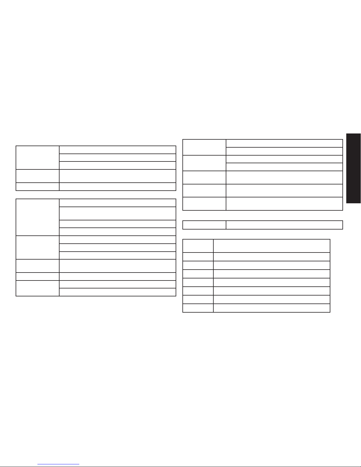
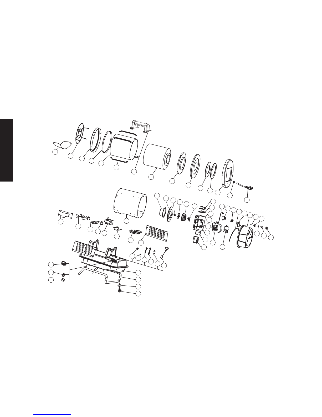
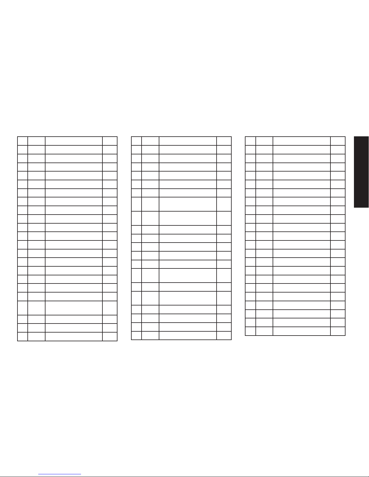
EXPLODED VIEW AND PARTS LIST 8
WIRING DIAGRAM 10
WARRANTY 11
Heater Specications
WARNING: If the information in this manual is not followed
exactly, a fire or explosion may result causing injury or loss of
life.
- Do not store or use gasoline or other flammable vapors and liquids in the
vicinity of this or any other appliance.
- Service must be performed by a qualified service agency.
WARNING
Not suitable for use on wood floors or other combustible materials. When
used the heater should rest on a suitable insulating material at least 1 inch
thick and extending 3 feet or more beyond the heater in all directions.
CAUTION: CSA certied for use with only No. 1-K kerosene fuel.
Factory Tested: Kerosene, Diesel #1 and #2, Fuel Oil #1 and #2, JP8
(Jet A Fuel)
MODEL NO.: ............................................................................. DXH70KTFRHC
BTU/hr: .......................................................................................70,000 BTU/hr
(20.5 kW)
CONSUMPTION RATE: ..................................................................0.52 GAL/hr
(1.97 L/hr)
TANK CAPACITY: ......................................................................2.77 GALLONS
(10.5 L)
RUN TIME: ....................................................................................... 5.34 hours
ELECTRICAL INPUT: .................................................................... 115 V, 60 HZ
ASSEMBLED DIMENSIONS: ...........................................13.25” X 25” X 22.25”
(33.6 cm X 63.5 cm X 56.5 cm)
DRY WEIGHT: ........................................................................40 lbs. (18.14 kg)
FULL WEIGHT: ......................................................................... 44 lbs. (20.0 kg)
APPROXIMATE HEATING AREA: ............................ 1750 SQ. FT (162.5 SQ. m)
THERMOSTAT RANGE: .................................... 41°F to 99°F ( 5 °C to 37.2 °C )
DEFAULT THERMOSTAT SETTING: .............................................68 °F ( 20 °C )
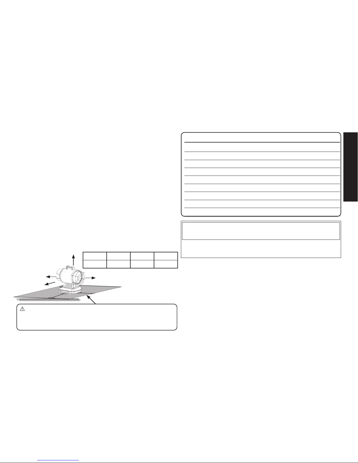
Clearance To Combustibles
From Outlet From Sides From Top From Rear
8 ft (2.44m) 3ft (0.9 m) 3ft (0.9 m) 3ft (0.9 m)
Top
Floor
Rear
Sides
Outlet
3 ft (0.91 m)
3 ft (0.91 m)
Page 4

English
4
Operating Precautions
This is a kerosene, direct-fired, radiant heater. It’s intended use is primarily temporary
heating of buildings under construction, alteration or repair.
Direct-Fired means that all of the combustion products enter the heated space. Even
though this heater operates very close to 100 percent combustion efficiency, it still
produces small amounts of carbon monoxide. Carbon monoxide (called CO) is toxic.
CO can build up in a heated space and failure to provide adequate ventilation could
result in death. The symptoms of inadequate ventilation are:
• Headache
• Dizziness
• Burning eyes and nose
• Nausea
• Dry mouth or sore throat
Be sure to follow advice about ventilation in the Safety Precautions section.
Forced Air means that a blower or fan pushes the air through the heater. Proper
combustion depends upon this air flow; therefore, the heater must not be revised,
modified or operated with parts removed or missing. Likewise, safety systems must
not be circumvented or modified in order to operate the heater.
When the heater is to be operated in the presence of other people the user is
responsible for properly acquainting those present with the safety precautions and
instructions, and of the hazards involved.
Safety Precautions
THIS IS A HEATING APPLIANCE. DO NOT ATTEMPT TO WARM OR COOK
FOOD ON THIS HEATER.
1. Recommended for use with No.1-K kerosene fuel. Factory tested for use with No.2-K
kerosene, No.1 or No.2 Diesel, No.1 or No.2 fuel oil or JP8 Jet A fuel and these fuels may
be used as well. Never use gasoline, biodiesel, oil drained from crank cases, naphtha, paint
thinners, alcohol or any other highly flammable fuels.
2. Check the heater thoroughly for damage. DO NOT operate a damaged heater.
3. DO NOT modify the heater or operate a heater which has been modified from its
original condition.
4. Suitable for outdoor use. For either outdoor or indoor use where adequate ventilation
is provided. Never use in areas normally for habitation. Not for use where exposed to
weather.
5. Use in well ventilated areas, provide at least 2 sq. ft. (0.19 sq. m.) of opening near
the floor and 2 sq. ft. (0.19 sq. m.) near the ceiling directly to outdoors. Increase air
openings as marked for each additional heater.
6. Always keep combustibles, like paper and wood at least 8 ft. from the heater
outlet and 3’ from the top, sides and inlet. Locate 8 ft. from canvas or plastic
coverings and secure them to prevent flapping movement.
7. Caution: Due to the high surface and exhaust temperatures, adults and children
must observe clearances to avoid burns or clothing ignition. Do Not Touch. Keep
children, clothing, and combustible away.
8. Install the heater such that it is not directly exposed to water spray, rain and / or
water.
9. Never use in areas normally for habitation and /or where children may be present.
10. Always operate only on a stable, level surface.
11. Do not use with duct work. Do not restrict inlet or exit.
12. Use only with electrical power specified. The electrical connection and grounding
must comply with National Electrical Code – ANSI/NFPA 70 (USA) and CSA
C22.1 Canadian Electrical Code, Part 1 (Canada).
13. Use only a properly grounded 3 pronged receptacle or extension cord.
14. Do not move, handle, or service while hot or in operation.
15. Use only in accordance with local, state (provincial) or national requirements,
ordinances and codes.
Operating Instructions
UNPACKING
1. Remove heater from carton.
2. Remove all protective material which may have been applied to the heater for shipment.
3. Check the heater for possible shipping damage. If any damage is found immediately
contact the manufacturer at 855-805-5745.
ASSEMBLY
1. First Locate the hardware package. You will find four long screws for the base
tubing, along with 4 nuts and washers. Place the heater on the base tubing as
shown on the front of this manual or in the parts diagram. Use the long screws and
matching fasteners to attach the base to the fuel tank.
2. In the hardware package you will also find two shorter washer headed screws for
attaching the handle to the top of the heater. Using a Phillips headed screw driver,
attach the handle to the top of the heater as shown on the front of this manual or in
the parts diagram.
3. Finally install the lower heat shield. The included heat shield will be located
centered at the 6 o’clock position. Only two screws are used to hold the shield in
Page 5

5
English
place. The middle hole is only for the locating pin that receives no fastener. Simply
remove the screws that line up with the holes on the heat shield when on the
centering pin. Put the heat shield into place and re-attach the screws.
PREPARATION FOR OPERATION
1. Check the heater for possible shipping damage. If any is found, immediately
contact the manufacturer at 855-805-5745.
2. Follow all of the “Operation Precautions” and “Safety Precautions”.
3. Fill the fuel tank with clean kerosene. In extremely cold weather, condensation may
develop in the tank and it is recommended that a tablespoon of de-icer be added
for each gallon (4 liters) of fuel in the tank. When filling the heater, use at least 2
gallons (8 liters) of fuel. Be sure heater is level and do not overfill. Use a funnel or
can with a long fill spout.
IMPORTANT: Before lling fuel tank the rst time or after extended storage
periods, drain the fuel tank of any moisture or condensation.
4. Locate heater at a safe distance from combustible materials. Not suitable for use
on wood floors or other combustible materials. When used, the heater should
rest on suitable insulating material at least 1 inch thick and extending 3 ft. or more
beyond the heater in all directions.
HEATER START UP
1. Locate the power plug near the controls of the heater. Using a properly sized
and grounded extension cord plug in the unit.
2. When power reaches the heater the Red light on the back of the heater will
illuminate.
3. Turn the power switch to the ON position. The LED read out will show the
approximate room temperature. When you turn the thermostat knob clockwise
the LED readout will change to show the set temperature. When that number
is higher than the room temperature the heater will begin is sequence of
operation.
4. Once the heater begins to run it will cycle on and off based on the thermostat
setting. If for any reason your heater does not run properly refer to the
Diagnostic and trouble shooting section in this manual or contact the
manufacturer with one of the methods listed on the back page of this manual.
HEATER SHUT DOWN
To turn off either turn the thermostat knob to a temperature lower than the room
temperature or move the power switch to the off position.
NOTICE: The heater is engineered with an integrated 3 minute cooling cycle
designed to prolong the life of internal components and to reduce surface
temperatures that tend to increase shortly after shutdown. Please allow this cycle to
complete before removing power from the heater.
Maintenance and Storage
Daily Maintenance Schedule
1. GENERAL. Make general visual inspection of heater for loose or damaged parts.
Check nuts and bolts to insure against looseness caused by vibration or rough
handling. Damaged parts should be repaired or replaced before using heater
again. Check heater operation to be sure it is operating normally (See “Servicing”
section for description of normal operation).
2. FILTERS. Dirty fuel filters will cause an imbalance in the air-fuel mixture. The best
indication that this condition exists is an increase in odors or difficulty getting your
heater to ignite. This heater should never be operated without the filter in place.
Contact DeWALT for replacement parts
500 Hour Maintenance schedule
1. REMOVE DUST. Clean heater twice a season (more often under dusty conditions).
Remove accumulated dust from the burner, motor and fan blades with
compressed air. Wipe area clean with a clean dry cloth. Inspect area to insure all
foreign materials are removed, especially around the burner and combustion area.
2. CAD CELL. Clean the glass portion of the cad cell with a soft dry cloth.
3. NOZZLE. Accumulation of dirt and carbon from the combustion process can
eventually fill up the passages in the nozzle, resulting in reduction of fuel and air
flow. If this occurs, replace the fuel nozzle. Contact DeWALT for service parts
4. FUEL TANK. Clean twice a season (during frequently used periods, clean twice a
month). Drain and flush the fuel tank with clean fuel oil.
Page 6

English
6
ANNUAL MAINTENANCE SCHEDULE
1. FUEL FILTER. Remove the fuel filter from fuel line and direct compressed air
through the filter in the opposite direction of fuel flow. Safety glasses should be
worn when using compressed air.
2. FUEL LINES. If the fuel lines are removed during cleaning, be sure all connections
are tight before operating unit. If any dry rotting or cracking in the lines is observed
replace with 1/4” id fuel line or contact DeWALT for service parts.
STORAGE
Store the heater in a dry location free from fumes or dust.
At the end of each heating season, clean the heater as described in the
MAINTENANCE section. Drain and flush the fuel tank with clean fuel. The
manufacturer recommends completely filling the tank with fuel for extended storage
to minimize condensation inside the tank.
It is recommended to only store kerosene in containers that are marked
“KEROSENE”.
SERVICING
A hazardous condition may result if a heater is used that has been modified or is not
functioning properly. When the heater is working properly:
* The flame is contained within the heater.
* The flame is essentially blue with perhaps some yellow tipping.
* There is no strong disagreeable odor, eye burning or other physical discomfort.
* There is no smoke or soot internal or external to the heater.
* There are no unplanned or unexplained shut downs of the heater.
The parts lists and exploded view show the heater as it was constructed. Do not
use a heater which is different from that shown. In this regard, use only the hose,
regulator and cylinder connection fitting (called a POL fitting) supplied with the heater.
Page 7
7
English
Diagnostic Safety Shutdown and Trouble Shooting
MOTOR DOES NOT START AND NO IGNITION
No electrical current
Check power supply (is it plugged in?)
Check proper position of the switch (is it on?)
Check fuse/breaker
Wrong setting on
thermostat
Check for setting of thermostat higher than room temp.
Defective motor Replace Motor
MOTOR STARTS NO IGNITION OR CUTS OUT
Not enough fuel at
the burner
Ensure an adequate level of fuel is in the tank.
Cycle unit a few time to allow fuel to fill the filter and fuel
system.
Check fuel lines including filter for leaks.
Clean or replace nozzle.
Electronic igniter
defective
Check igniter connections including transformer
Check electrodes for corrosion and carbon build up.
Replace transformer
Flame control box
defective
Replace flame control box
Photocell defective Clean or replace photo cell
Solenoid defective
Check connections
Replace solenoid
MOTOR STARTS, HEAT EMITS SMOKE
Not enough combustion air
Make sure Air inlet and outlet are free
Clean burner disc
Fuel contaminated
or contains water
Drain fuel in tank and replace with clean fuel
Clean or replace fuel filter
Air leaks in fuel
circuit
Check fuel lines and system for possible leaks
Not enough fuel at
burner
Clean or replace fuel nozzle
Too much fuel at
burner
Replace nozzle
HEATER DOES NOT STOP
Solenoid defective Replace solenoid
LED DIAGNOSTIC READ OUT TABLE
ERROR
CODE
DESCRIPTION
E1 Ignition failed or flame out
E2 Temperature sensor malfunction
E3 High limit switch over heat
E4 Flame control malfunction
E5 Solenoid monitor malfunction
E6 Photo cell fault
E7 Motor Speed fault
Page 8
English
8
1
2
27
28
3
4
5
6
7
8
9
10
11
12
13
14
15
16
17
18
19
19
20
21
22
23
24
25
26
29
30
55
56
31
32
33
34
35
39
42
43
44
45
46
47
48
49
50
51
52
53
54
57
58
59
60
61
62
63
36
37
38
40
41
Page 9
9
English
# P/N DESC. QTY
1 22300 Oil drain Plug 1
2 NA Drain plug O-ring 1
3 22302 Tank support foot 1
4 22303 Fuel tank 1
5 22304 Fill spout filter holder 1
6 22305 Fill spout Filter 1
7 22306 Fuel cap 1
8 NA Spring clamp 1
9 NA Fuel return line o-ring 1
10 22308 Fuel return stem 1
11 22309 Fuel pickup with filter 1
12 22311 Fuel filter 1
13 22312 Fuel level float and gauge 1
14 NA Side plate 2
15 NA Motor support 1
16 22315 External shell 1
17 22316 Air flow blower motor 1
18 NA Flue support bracket 4
19 NA Motor mounting support
bracket
2
20 22319 Air flow fan blade 1
21 NA Flue ring 1
22 NA Air Collection ring 1
# P/N DESC. QTY
23 NA Seal plate 1
24 22323 Nozzle 1
25 22324 Swirl plate 1
26 NA Burner head 1
27 22326 Igniter 1
28 22327 Control board 1
29 NA Control board mounting
bracket
1
30 NA Control systems mounting
bracket
1
31 22330 High limit switch 1
32 NA Photocell bracket 1
33 22332 Photocell 1
34 NA Ignition transformer bracket 1
35 22334 Ignition transformer 1
36 22335 Combustion blower as-
sembly
1
37 22336 Fuel supply line 1
38 NA Solenoid valve (comb. w/
pump)
1
39 22338 Solenoid pump 1
40 22339 Tip-over switch 1
41 NA Waterproof gasket 1
42 22341 Thermostat control board 1
# P/N DESC. QTY
43 22342 Rear plastic cover 1
44 NA Led Lens 1
45 NA LED display lens 1
46 NA Thermostat retention nut 1
47 22346 On/Off Switch 1
48 22347 Thermostat knob 1
49 NA Power cord 1
50 NA strain relief 1
51 22350 Rear cover 1
52 NA Seal ring 1, outer 1
53 NA seal ring 2, inner 1
54 NA Heat Shield 1
55 NA Combustion chamber rear 1
56 NA Combustion chamber rear 1
57 22356 Carry Handle 1
58 NA Air gap bracket 1
59 22358 Combustion chamber 1
60 NA Front combustion ring 1
61 NA External retention ring 1
62 22361 Front safety guard 1
63 22362 Lower heat Shield 1
** NA Hardware Kit (not shown) 1
Page 10
English
10
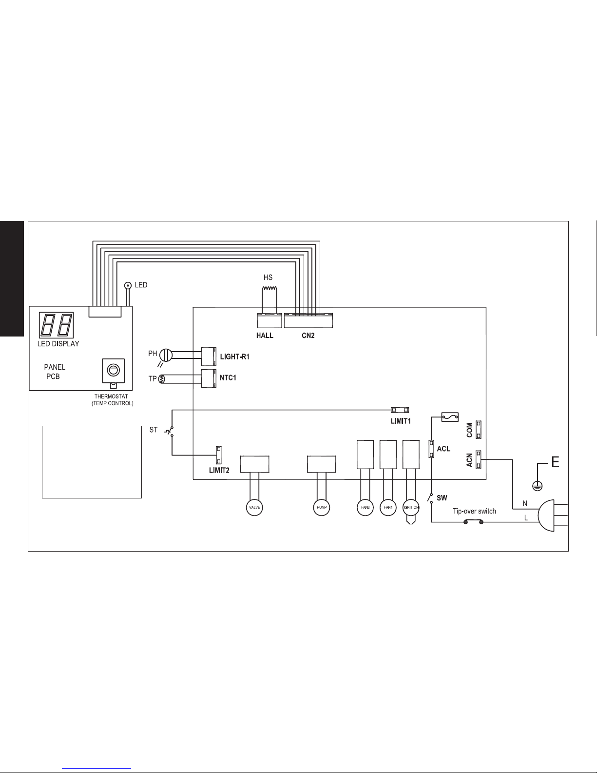
WIRING DIAGRAM
The parts lists and wiring diagram show the heater as it was constructed.
Do not use a heater which is different from that shown. Heater
performance is effected by air pressure setting. If there is any uncertainty
about the air pressure setting, have it checked. A heater which is not
working right must be repaired, but only by a trained, experienced service
person.
HS: hallsenor
PH: photocell
TP: temp probe
SW: switch
ST: safety thermostat
Page 11

11
English
INSTRUCTION MANUAL
Kerosene Forced Air Heater
DXH70KTFRHC
DEWALT®, GUARANTEED TOUGH® and the
yellow and black color scheme are trademarks
of the DEWALT Industrial Tool Co., used under
license. ©2017 DEWALT. EGI/Enerco Group Inc.
Under license from Dewalt Industrial Tool Co
Warning
USE ONLY MANUFACTURER’S REPLACEMENT PARTS. USE OF ANY
OTHER PARTS COULD CAUSE INJURY OR DEATH. REPLACEMENT PARTS
ARE ONLY AVAILABLE DIRECT FROM THE FACTORY AND MUST BE
INSTALLED BY A QUALIFIED SERVICE AGENCY.
PARTS ORDERING INFORMATION:
PURCHASING: Accessories may be purchased at any Dewalt® local dealer or
direct from the factory
FOR INFORMATION REGARDING SERVICE:
Please call Toll-Free 855-805-5745
www.dewalt.com
Our office hours are 8:00 AM – 5:00 PM, EST, Monday through Friday.
Please include the model number, date of purchase, and description of
problem in all communication.
LIMITED WARRANTY
DeWalt® warrants its heaters and accessories to be free from defects in material and workmanship for a period of 1 year from date of purchase.
DeWalt® will repair or replace this product free of charge if it has been prove
to be defective within the 1 year period, and is returned at customer expense
with proof of purchase to DeWalt® within the warranty period.
Page 12

Français
2
AVERTISSEMENT: NON CONÇU POUR ÊTRE UTILISÉ DANS UNE
HABITATION OU UN VÉHICULE RÉCRÉATIF.
AVERTISSEMENT G
ÉNÉRAL DE DANGER
:
LE NON-RESPECT DES MESURES DE PRÉVENTION ET INSTRUCTIONS
FOURNIES AVEC CET APPAREIL DE CHAUFFAGE RISQUE DE CAUSER LA MORT,
DES BLESSURES GRAVES ET DES DOMMAGES OU DES PERTES MATÉRIELLES
RÉSULTANT D’INCENDIE, D’EXPLOSION, DE BRÛLURE, D’ASPHYXIE,
D’INTOXICATION AU MONOXYDE DE CARBONE OU D’ÉLECTROCUTION.
SEULES LES PERSONNES APTES À COMPRENDRE ET À RESPECTER LES
INSTRUCTIONS DEVRAIENT UTILISER OU EFFECTUER L’ENTRETIEN DE CET
APPAREIL DE CHAUFFAGE.
SI VOUS AVEZ BESOIN D’AIDE OU D’INFORMATION AU SUJET DE L’APPAREIL
DE CHAUFFAGE (MANUEL D’INSTRUCTIONS, ÉTIQUETTES, ETC.), VEUILLEZ
COMMUNIQUER AVEC LE FABRICANT.
AVERTISSEMENT:
DANGER D’INCENDIE, D’EXPLOSION ET D’INHALATION.
CONSERVEZ LES MATÉRIAUX COMBUSTIBLES TELS QUE LES MATÉRIAUX DE
CONSTRUCTION, LE PAPIER ET LE CARTON À UNE DISTANCE SÉCURITAIRE DE
L’APPAREIL DE CHAUFFAGE COMME LE RECOMMANDENT LES INSTRUCTIONS.
N’UTILISEZ JAMAIS L’APPAREIL DE CHAUFFAGE DANS UN LOCAL QUI CONTIENT
OU RISQUE DE CONTENIR DES PARTICULES COMBUSTIBLES EN SUSPENSION
DANS L’AIR OU DES PRODUITS TELS QUE DE L’ESSENCE, DES SOLVANTS, DU
DILUANT À PEINTURE, DES PARTICULES DE POUSSIÈRE OU DES PRODUITS
CHIMIQUES INCONNUS.
AVERTISSEMENT: LE MONOXYDE DE CARBONE PEUT VOUSTUER
UTILISATION D’UN CHAUFFE PORTABLE DANS UN ESPACE CLOS PEUT PRODUIRE
AU MONOXYDE DE CARBONE MORTEL.
Cet appareil de chauffage portatif n’est pas ventilé. Il utilise l’oxygène de l’air
ambiant. Une circulation d’air adéquate doit être assurée pour la combustion et
la ventilation. Voir page3.
WARNINGS
AVERTISSEMENT:
• N’EMPLOYEZ PAS D’ESSENCE, DE NAPHTE OU DE PRODUITS
COMBUSTIBLES VOLATILS.
• ARRÊTEZ L’APPAREIL DE CHAUFFAGE AVANT D’Y AJOUTER DU
COMBUSTIBLE.
• REMPLISSEZ TOUJOURS LE RÉSERVOIR À L’EXTÉRIEUR, LOIN D’UNE
FLAMME NUE.
• N’UTILISEZ PAS DE SOURCE DE COMBUSTIBLE EXTERNE.
• NE FAITES PAS FONCTIONNER L’APPAREIL DE CHAUFFAGE SI DES VAPEURS
OU DES LIQUIDES INFLAMMABLES RISQUENT D’ÊTRE PRÉSENTS.
• NE DÉMARREZ PAS L’APPAREIL DE CHAUFFAGE SI LA CHAMBRE DE
COMBUSTION EST CHAUDE.
• NE DÉMARREZ PAS L’APPAREIL DE CHAUFFAGE SI UN SURPLUS DE
COMBUSTIBLE S’EST ACCUMULÉ DANS LA CHAMBRE DE COMBUSTION.
• NE PLACEZ PAS D’USTENSILES DE CUISSON SUR L’APPAREIL DE
CHAUFFAGE.
• BRANCHEZ LE CORDON ÉLECTRIQUE DANS UNE PRISE À TROIS BROCHES
ADÉQUATEMENT MISE À LA TERRE.
Dénitions : Directives de sécurité
Les dénitions ci-dessous décrivent le niveau de sévérité pour chaque mot signalétique. Veuillez lire le manuel et faire attention à ces symboles.
DANGER : Indique « une situation à risque imminent, laquelle, si elle n’est pas évitée, entraînera des blessures sérieuses ou la mort ».
AVERTISSEMENT :
Indique « une situation à risque potentiel, laquelle si elle n’est pas évitée, pourrait entraîner des blessures sérieuses ou la mort ».
MISE EN GARDE : Indique une situation dangereuse potentielle, laquelle, si elle n’est pas évitée, peut causer des blessures mineures ou des blessures légères.
AVIS : Indique une pratique non reliée à une blessure personnelle, laquelle, si elle n’est pas évitée, peut entraîner des dommages aux biens.
AVERTISSEMENT: LES SOUS-PRODUITS DE COMBUSTION ÉMIS LORS DE
L’UTILISATION DE CET APPAREIL CONTIENNENT DU MONOXYDE DE CARBONE, UN PRODUIT CHIMIQUE RECONNU PAR L’ÉTAT DE CALIFORNIE COMME
POUVANT CAUSER LE CANCER ET DES MALFORMATIONS CONGÉNITALES (OU
AUTRES DOMMAGES AU SYSTÈME REPRODUCTEUR). Pour plus d’informations,
visitez www.P65Warnings.ca.gov
Page 13

3
Français
CONTENTS
AVERTISSEMENTS 2
SPÉCIFICATIONS DU RADIATEUR 3
PRÉCAUTIONS DE SÉCURITÉ ET D’OPÉRATION 4
INSTRUCTIONS DE FONCTIONNEMENT 4
ENTRETIEN ET ENTREPOSAGE 5
DÉPANNAGE 7
LISTE DES PIÈCES 8
SCHÉMA DE CÂBLAGE 10
GARANTIE 11
Spécications du Radiateur
AVERTISSEMENT : Si l’information décrite dans ce manuel n’est
pas respectée exactement, un incendie ou une explosion peut en
résulter, et cela peut causer des dommages à la propriété, une
blessure personnelle ou un décès.
- Ne pas ranger ni utiliser d’essence ou d’autres liquides ou émanations
inflammables à proximité de cet appareil, ou de tout autre appareil.
- Tout service doit être effectué par une agence qualifiée de service.
WARNING
Cet appareil n’est pas conçu pour être utilisé sur les planchers de bois ou d’autres matériaux combustibles. Lorsqu’il est utilisé, le radiateur doit être muni d’un
matériau d’isolation adéquat d’au moins 2,5 cm (1 po) d’épaisseur et s’étendant
au-delà du radiateur d’au moins 0,9 m (3 pi) dans toutes les directions.
MISE EN GARDE: Homologué CSA pour utilisation seulement avec du kérosène no 1-K.
Testés à l’usine : Kérosène, diesel no 1 et no 2, mazout no 1 et no 2, JP8 (carburant d’aviation de type A)
MODÈLE: .................................................................................. DXH70KTFRHC
ÉVALUÉE À ................................................................................70,000 BTU/hr
(20.5 kW)
TAUX DE CONSOMMATION: .........................................................0.52 GAL/hr
(1.97 L/hr)
CAPACITÉ DU RÉSERVOIR: ......................................................2.77 GALLONS
(10.5 L)
DURÉE DE FONCTIONNEMENT: ..................................................... 5.34 hours
DONNÉES ÉLECTRIQUES: .......................................................... 115 V, 60 HZ
DIMENSIONS (ASSEMBLÉ): ...........................................13.25” X 25” X 22.25”
(33.6 cm X 63.5 cm X 56.5 cm)
POIDS À SEC: .......................................................................40 lbs. (18.14 kg)
OIDS LORSQUE PLEIN: ...........................................................44 lbs. (20.0 kg)
ZONE APPROXIMATIVE DE CHAUFFAGE: ............. 1750 SQ. FT (162.5 SQ. m)
PLAGE DU THERMOSTAT: ............................... 41°F to 99°F ( 5 °C to 37.2 °C )
RÉGLAGE PAR DÉFAUT DU THERMOSTAT: ................................68 °F ( 20 °C )
DÉGAGEMENT AVEC LES MATIÈRES COMBUSTIBLES
De la sortie Des côtés De haut De l’arrière
8 pi (2,44m) 3pi (0,9 m) 3pi (0,9 m) 3pi (0,9 m)
Haut
Du plancher
Arrière
Côtés
Sortie
3 ft (0.91 m)
3 pi (0.9 m)
Page 14

Français
4
Précautions d’opération
Cet appareil est un radiateur au kérosène, à feu direct, radiant. Il est conçu pour
usage principal de chauffage temporaire des immeubles en construction, en
rénovation ou en réparation.
Le terme feu direct signifie que tous les produits de combustion entrent dans la
zone chauffée. Bien que ce radiateur fonctionne à près de 100 % d’efficacité de
combustion, il produit quand même des petites quantités de monoxyde de carbone.
Le monoxyde de carbone (appelé communément CO) est toxique. Le CO peut
s’accumuler dans l’espace chauffé et un manquement à fournir une ventilation
adéquate peut entraîner un décès. Voici les symptômes d’une ventilation inadéquate :
• Mal de tête
• Étourdissement
• Yeux et le nez qui piquent/brûlent
• Nausée
• Bouche sèche ou mal de gorge
Assurez-vous de respecter les avis concernant la ventilation dans la section des
précautions de sécurité.
Le terme ventilation forcée signifie qu’une soufflante ou un ventilateur pousse l’air
au travers du radiateur. La bonne combustion dépend de ce courant d’air; en
conséquence, le radiateur ne doit pas être révisé, modifié ou opéré avec des pièces
retirées ou manquantes. Aussi, les systèmes sécurité ne doivent pas être circonvenus
ou modifiés pour faire fonctionner le radiateur.
Lorsque le radiateur doit fonctionner en présence d’autres personnes, l’utilisateur est
responsable d’aviser adéquatement ces personnes sur les précautions de sécurité, sur
les instructions, et sur les risques impliqués.
Précautions de Sécurité
CECI EST UN APPAREIL DE CHAUFFAGE. N’ESSAYEZ PAS DE CHAUFFER
OU DE CUIRE DES ALIMENTS SUR CE RADIATEUR.
1. Recommandé pour utilisation avec du kérosène no 1-K seulement. Testé à l’usine
pour usage avec du kérosène, du diesel no 1 et no 2, du mazout no 1 et no 2, du JP8
(carburant d’aviation de type A), et ces carburants peuvent aussi être utilisés. Ne jamais
utiliser de l’essence, du biodiesel, de l’huile drainée des carters de moteur, du Naphta, du
diluant à peinture, de l’alcool ni tout autre carburant hautement inflammable.
2. Inspecter minutieusement le radiateur pour la présence de dommage. Ne pas faire
fonctionner un radiateur endommagé.
3. Ne pas modifier le radiateur ni faire fonctionner un radiateur dont la condition d’origine
aurait été modifiée.
4. Adéquat pour usage à l’extérieur. Pour usage à l’intérieur ou à l’extérieur lorsqu’une
ventilation adéquate est fournie. Ne jamais utiliser dans des zones normales
d’habitation. Ne pas l’utiliser si exposé aux intempéries.
5. Utiliser dans des zones bien ventilées, fournir une ouverture d’au moins 0,19 m² (2 pi²)
près du sol et de 0,19 m2 (2 pi²) près du plafond donnant directement vers l’extérieur.
Augmenter les ouvertures d’air tel qu’indiqué, pour chaque radiateur additionnel.
6. Garder toujours les combustibles, comme le papier et le bois, à une distance
d’au moins 2,4 m (8 pi) de la sortie du radiateur et à 0,9 m (3 pi) du haut, des
côtés et de l’entrée. Distancer de 2,4 m (8 pi) des canevas ou des couvertures en
plastique, et bien les attacher pour prévenir tout mouvement.
7. Mise en garde : En raison des hautes températures de surface et d’évacuation, les
adultes et les enfants doivent respecter les dégagements pour éviter les brûlures
ou l’ignition des vêtements. Ne pas toucher. Garder les enfants, les vêtements, et
les combustibles éloignés.
8. Installer le radiateur de sorte qu’il ne puisse pas être exposé directement à de
l’eau pulvérisée, à de la pluie et/ou à de l’eau.
9. Ne jamais l’utiliser dans des zones qui sont normalement prévues pour habitation
et/ou là où des enfants pourraient être présents.
10. Toujours faire fonctionner cet appareil uniquement sur une surface stable et à
niveau.
11. Ne pas utiliser avec des gaines et conduits d’air. Ne pas restreindre l’entrée ou
la sortie.
12. Utiliser uniquement avec une alimentation électrique telle que spécifiée. La
connexion électrique et la mise à la terre doivent respecter le Code national
d’électricité – ANSI/NFPA 70 (États-Unis) et le Code canadien d’électricité CSA
C22.1, section 1 (Canada).
13. Utiliser seulement une fiche ou une rallonge à 3 alvéoles et mise à la terre
adéquate.
14. Ne pas déplacer, manipuler ou effectuer un service pendant qu’il est chaud ou
qu’il fonctionne.
15. Utiliser seulement en conformité avec les exigences et ordonnances des codes
locaux, de l’état (province) et nationaux.
Instructions de Fonctionnement
DÉBALLAGE
1. Sortir le radiateur de la boîte.
2. Retirer tout le matériel de protection qui pourrait avoir été appliqué sur le radiateur pour
Page 15

5
Français
l’expédition.
3. Inspecter le radiateur pour la présence possible de dommage survenu pendant
l’expédition. Si un dommage est découvert, communiquer immédiatement avec le
fabricant au numéro 855-805-5745.
ASSEMBLAGE
1. Localiser d’abord l’ensemble de quincaillerie. Vous trouverez quatre grandes vis
pour le tubage de la base, ainsi que 4 écrous et rondelles. Placer le radiateur
sur le tubage de la base tel qu’illustré sur le devant de ce manuel ou dans le
diagramme des pièces. Utiliserla grande vis et les fixations apparentées pour fixer
la base au réservoir de carburant.
2. Se trouvent dans l’ensemble de quincaillerie deux vis plus courte avec rondelle
pour la fixation de la poignée au dessus du radiateur. À l’aide d’un tournevis
cruciforme, fixer la poignée au dessus du radiateur tel qu’illustré sur le devant de
ce manuel ou dans le diagramme des pièces.
3. Finalement, installer le protecteur thermique inférieur. Le protecteur thermique
compris doit être situé au centre à la position correspondant à 6 heures.
Seulement deux vis sont utilisées pour retenir le protecteur en place. Le trou du
milieu est dédié uniquement à la tige de localisation qui ne reçoit pas de fixation.
Retirer simplement la vis qui s’aligne avec les trous sur le protecteur thermique,
lorsque sur la vis de centrage. Mettre le protecteur thermique en place et resserrer
la vis.
PRÉPARATION POUR LE FONCTIONNEMENT
1. Inspecter le radiateur pour la présence possible de dommage survenu pendant
l’expédition. Si un dommage est découvert, communiquer immédiatement avec le
fabricant au numéro 855-805-5745.
2. Respecter toutes les « mises en garde et avertissements ».
3. Remplir le réservoir de carburant avec du kérosène propre. Dans des conditions
de grand froid, une condensation pourrait se développer dans le réservoir et il est
recommandé d’ajouter une cuillère à table de liquide de dégivrage pour chaque
gallon (4 litres) de carburant dans le réservoir. Lors du remplissage du radiateur,
utiliser au moins 2 gallons (8 litres) de carburant. S’assurer que le radiateur est
bien à niveau et ne pas trop le remplir. Utiliser un entonnoir ou un contenant muni
d’un long bec.
IMPORTANT: Avant de remplir le réservoir de carburant pour la première
fois, ou après des périodes de rangement prolongées, drainer le réservoir de
carburant de toute humidité ou condensation.
4. Localiser le radiateur à une distance sécuritaire des matériaux combustibles.
Consulter le tableau des spécifications dans ce manuel pour déterminer les
bonnes distances.
DÉMARRAGE DU RADIATEUR
1. Localiser la fiche d’alimentation près des contrôles du radiateur. Brancher
l’appareil à l’aide d’une rallonge de taille appropriée et munie d’une mise à la
terre adéquate.
2. Quand le radiateur est alimenté, le témoin lumineux rouge s’illuminera, à
l’arrière du radiateur.
3. Placer le commutateur à la position de marche (ON). L’afficheur à DEL
indiquera la température approximative de la pièce. Lorsqu’on tourne le
bouton du thermostat en sens horaire, l’afficheur à DEL changera pour afficher
le point de réglage de température. Quandce nombre est plus élevé que la
température de la pièce, le radiateurlancera sa séquence de fonctionnement.
4. Après que le radiateur ait commencé à fonctionner, il effectuera un cycle
allumé - éteint selon le réglage du thermostat. Si votre radiateur ne fonctionne
pas bien pour quelque motif, se référer à lasection de diagnostique et
dépannage dans ce manuel, ou communiquer avec le fabricant par l’une des
méthodes listées à l’endos de ce manuel.
ARRÊT DU RADIATEUR
Pour éteindre le radiateur, on peut au choix régler le bouton du thermostat à une
température inférieure à la température de la pièce ou placer le commutateur
marche/arrêt à la position d’arrêt (OFF).
REMARQUE: Ces radiateurs sont conçus avec un cycle intégré de 3 minutes de
refroidissement, destiné à prolonger la durée de vie des composantes internes et
pour abaisser les températures de surface qui tendent à augmenter un peu après
l’extinction. Veuillez laisser ce cycle se terminer avant de couper l’alimentation du
radiateur.
Entretien et Entreposage
Programme Quotidien
1. GÉNÉRAL. Faites une inspection visuelle générale de l’appareil de chauffage
pour déceler les pièces endommagées ou desserrées. Inspectez les boulons et
les écrous pour vous assurer que les vibrations et les manipulations brusques
ne les ont pas desserrés. Les pièces endommagées doivent être réparées ou
Page 16

Français
6
remplacées avant d’utiliser à nouveau l’appareil de chauffage. Vérifiez si l’appareil
fonctionne normalement (consultez la section «Réparation» pour une description
du fonctionnement normal).
2. FILTRES. Les filtres à air et à combustible doivent être propres pour assurer
l’équilibre du mélange air-combustible. À défaut de quoi, l’odeur augmentera et
l’appareil de chauffage démarrera difficilement. Ne faites pas fonctionner l’appareil
sans les filtres. Si nécessaire, nettoyez les filtres tel qu’il est décrit aux sections
«Programme 500 heures» et «Programme annuel»
PROGRAMME AUX 500 HEURES
1. ENLÈVEMENT DE LA POUSSIÈRE. Nettoyez l’appareil de chauffage deux fois
par saison (plus souvent dans les endroits poussiéreux). Enlevez la poussière
accumulée sur le transformateur, le brûleur, le moteur et les pales du ventilateur à
l’aide d’un jet d’air comprimé. Essuyez les surfaces avec un chiffon sec et propre.
Inspectez ces endroits pour vous assurer que toute matière étrangère a été
enlevée, particulièrement autour du brûleur et de la zone de combustion.
2. CELLULE AU CADMIUM. Nettoyez la partie vitrée de la cellule au cadmium à
l’aide d’un chiffon doux et sec.
3. GICLEUR. L’accumulation de saleté de combustible et de carbone causée par
l’aube d’entrée obstruera éventuellement les conduits du gicleur et entraînera
une diminution du débit d’air et de combustible. La pression augmentera
graduellement, ce qui déséquilibrera le mélange air-combustible et produira un
surplus de fumée et d’odeur. Dans un tel cas, remplacez le gicleur.
4. RÉSERVOIR DE COMBUSTIBLE. Nettoyez-le deux fois par saison (au cours des
périodes d’utilisation intensive, nettoyez-le deux fois par mois). Rincez et vidangez
le réservoir à l’aide de mazout propre.
PROGRAMME ANNUEL
1. FILTRE DE CARBURANT. Sortir le filtre de carburant de la conduite de carburant
et diriger de l’air comprimé dans le filtre dans la direction opposée à l’écoulement
du carburant. Il est important de porter des lunettes de sécurité lors de l’utilisation
d’air comprimé.
2. CONDUITS DE CARBURANT. Si les conduits de carburant sont retirés pendant
le nettoyage, s’assurer que toutes les connections soient serrées avant de faire
fonctionner l’appareil. Si une craquelure sèche ou de la pourriture est détectée sur
les conduits, il faut le remplacer avec un conduit au diamètre intérieur de 1/4po,
ou communiquer avec Mr. Heater pour des pièces ou un service.
RANGEMENT
Ranger le radiateur dans un endroit sec et libre de toute émanation ou de poussière.
À la fin de chaque saison de chauffage, nettoyer le radiateur tel que décrit dans la
section ENTRETIEN. Drainer et rincer le réservoir de carburant avec du carburant
propre. Le fabricant recommande de remplir complètement le réservoir avec
du carburant pour une période prolongée de rangement, afin de minimiser la
condensation à l’intérieur du réservoir
Il est recommandé de stocké le kérosène uniquement dans des conteneurs portant
la mention «KÉROSÈNE».
SERVICE
Une condition dangereuse peut survenir si un radiateur qui a été modifié est utilisé,
ou s’il ne fonctionne pas correctement.
Quand le radiateur fonctionne normalement :
• La flamme est contenue dans le radiateur.
• Il n’y a pas d’odeur forte et désagréable, de brûlement des yeux ni d’autre
inconfort physique.
• Il n’y a pas de fumée ou de suies à l’intérieur ni à l’extérieur du radiateur.
• Il n’y a pas d’extinction inexpliquée ou non-planifiée du radiateur.
Page 17

7
Français
Dépannage et Diagnostique en Cas d’extinction de Sécurité
LE MOTEUR NE DÉMARRE PAS ET IL N’Y A PAS D’IGNITION
Pas de courant
électrique
Vérifier l’alimentation (bien connectée?)
Vérifier la bonne position du commutateur (allumé?)
Vérifier le fusible/disjoncteur
Mauvais réglage sur
le thermostat
Vérifier si le réglage du thermostat est plus élevé que la
température de la pièce
Moteur défectueux Remplacer le moteur
LE MOTEUR DÉMARRE, MAIS IL N’Y A PAS D’IGNITION OU ELLE
S’INTERROMPT
Pas assez de carburant au brûleur
S’assurer qu’il y a un niveau adéquat de carburant dans le
réservoir.
Faire cycler l’appareil quelque fois pour permettre au carburant de remplir le filtre et le système de carburant.
Vérifier les conduits de carburant, y compris le filtre, pour
la présence de fuite.
Nettoyer ou remplacer la buse.
Allumeur électronique défectueux
Vérifier les connexions de l’igniteur, y compris celles du
transformateur
Vérifier les électrodes pour une accumulation de corrosion
ou de carbone.
Remplacer le transformateur
Cabinet de contrôle
de flamme défectueux
Remplacer le cabinet de contrôle de flamme.
Photocellule défectueuse
Nettoyer ou remplacer la photocellule.
Solénoïde défectueux
Vérifier les connections
Remplacer le solénoïde
LE MOTEUR DÉMARRE, MAIS LE RADIATEUR ÉMET DE LA FUMÉE
Pas assez d’air de combustion
S’assurer que les entrées et sorties d’air sont
libres
Nettoyer le disque du brûleur
Carburant contaminé ou qui
contient de l’eau
Drainer le carburant dans le réservoir et le remplacer avec du carburant propre
Nettoyer ou remplacer le filtre de carburant
Fuites d’air dans le circuit de
carburant
Vérifier les conduits et le système de carburant
pour la présence de fuite
Pas assez de carburant au
brûleur
Nettoyer ou remplacer la buse de carburant
Trop de carburant au brûleur Remplacer la buse
LE RADIATEUR NE S’ARRÊTE PAS
Solénoïde défectueux Remplacer le solénoïde
TABLEAU DES LECTURES DU DIAGNOSTIQUE À DEL
CODE D’ERREUR DESCRIPTION
E1 Défaillance d’ignition ou extinction
E2 Défaillance du capteur de température
E3 Surchauffe du interrupteur de haute limite
E4 Défaillance du contrôle de flamme
E5 Défaillance de surveillance du solénoïde
E6 Défaillance de photocellule
E7 Faute de vitesse du moteur
Page 18

Français
8
1
2
27
28
3
4
5
6
7
8
9
10
11
12
13
14
15
16
17
18
19
19
20
21
22
23
24
25
26
29
30
55
56
31
32
33
34
35
39
42
43
44
45
46
47
48
49
50
51
52
53
54
57
58
59
60
61
62
63
36
37
38
40
41
Page 19

9
Français
# P/N DESC. QTY
1 22300 Bouchon de vidange d’huile 1
2 NA
Joint torique du bouchon de
vidange
1
3 22302 Trépied du réservoir 1
4 22303 Réservoir de carburant 1
5 22304
Retenue du bec du filtre de
remplissage
1
6 22305 Bec du filtre de remplissage 1
7 22306 Couvercle du carburant 1
8 NA Étrier de ressort 1
9 NA
Joint torique du conduit de
retour de carburant
1
10 22308 Tige de retour de carburant 1
11 22309
Alimentation en carburant avec
filtre
1
12 22311 Filtre de carburant 1
13 22312
Flotte de niveau et jauge de
carburant
1
14 NA Plaque latérale 2
15 NA Support du moteur 1
16 22315 Coque extérieure 1
17 22316 Moteur de soufflante d’air 1
18 NA
Support de montage du conduit
de cheminée
4
19 NA Support de montage du moteur 2
20 22319 Hélice du ventilateur d’air forcé 1
21 NA Anneau du conduit de cheminée 1
22 NA Anneau du collecteur d’air 1
23 NA Plaque d’étanchéité 1
24 22323 Buse 1
25 22324 Plaque à tourbillon 1
26 NA Tête du brûleur 1
27 22326 Igniteur 1
28 22327 Plaquette de contrôle 1
# P/N DESC. QTY
29 NA Support de montage de la 1
30 NA
Support de montage des sys-
tèmes de contrôle
1
31 22330 Interrupteur de haute limite 1
32 NA Support de photocellule 1
33 22332 Photocellule 1
34 NA
Support du transformateur
d’ignition
1
35 22334 Transformateur d’ignition 1
36 22335
Assemblage du ventilateur d’air
de combustion
1
37 22336
Conduit d’alimentation du
carburant
1
38 NA Électrovanne 1
39 22338 Pompe à solénoïde 1
40 22339 Interrupteur anti-basculement 1
41 NA Joint d’étanchéité imperméable 1
42 22341
Plaquette de contrôle du ther-
mostat
1
43 22342 Couvercle arrière en plastique 1
44 NA Lentilles à DEL 1
45 NA Lentilles de l’affichage à DEL 1
46 NA Écrou de retenue du thermostat 1
47 22346 Commutateur marche/arrêt 1
48 22347 Bouton du thermostat 1
49 NA Cordon d’alimentation 1
50 NA Collier de serrage 1
51 22350 Couvercle arrière 1
52 NA Joint d’étanchéité 1, externe 1
53 NA Joint d’étanchéité 2, interne 1
54 NA Protecteur thermique 1
# P/N DESC. QTY
55 NA
Arrière de la chambre de com-
bustion
1
56 NA
Arrière de la chambre de com-
bustion
1
57 22356 Poignée de transport 1
58 NA Support d’écartement 1
59 22358 Chambre de combustion 1
60 NA Anneau de combustion avant 1
61 NA Anneau externe de rétention 1
62 22361 Garde de sécurité avant 1
63 22362 Protecteur thermique inférieur 1
** NA Kit de quincaillerie (non illustré) 1
Page 20

Français
10
SCHÉMA DE CÂBLAGE
La liste des pièces et le schéma de câblage montrent le
radiateur tel qu’il a été construit. Ne pas utiliser un radiateur
qui diffère de cette illustration. La performance du radiateur est
affectée par le réglage de pression d’air. En cas d’incertitude
concernant le réglage de pression d’air, il faut faire vérifier votre
appareil.
Un radiateur qui ne fonctionne pas bien doit être réparé, mais
seulement par un technicien de service formé et expérimenté.
HS: capteur d’effet Hall
PH: photocellule
TP: sonde de température
SW: commutateur
ST: thermostat de sécurité
PLAQUETTE
DU PANNEAU
THERMOSTAT
(CONTRÔLE DE TEMPÉRATURE)
Interrupteur anti-basculement
VALVE POMPE
VENTILATEUR 1
VENTILATEUR 2
Allumage
LIMITE 1
LIMITE 2
AFFICHAGE À DEL
DEL
NTC1
TÉMOIN LUMINEUX -R1
Terre
Page 21

11
Français
GUIDE DE’UTILISATION
Radiateur au Kérosène à Ventilation Forcée
DXH70KTFRHC
Avertissement
UTILISER UNIQUEMENT LES PIÈCES DE RECHANGE D’ORIGINE
DU FABRICANT. L’UTILISATION D’AUTRES PIÈCES PEUT CAUSER
DES BLESSURES OU LA MORT. LES PIÈCES DE RECHANGE SONT
DISPONIBLES SEULEMENT DIRECTEMENT DU FABRICANT ET ELLES
DOIVENT ÊTRE INSTALLÉES PAR UNE AGENCE DE SERVICE QUALIFIÉE.
PARTS ORDERING INFORMATION:
PURCHASING: Accessories may be purchased at any Dewalt® local dealer or
direct from the factory
INFORMATION POUR LA COMMANDE DE PIÈCES:
APPROVISIONNEMENT : Il est possible d’acheter les accessoires auprès de
tout détaillant local DewaltMD ou alternativement, directement de l’usine
POUR DE L’INFORMATION CONCERNANT LE SERVICE:
Appeler sans frais au 855-805-5745
www.dewalt.com
Nos heures d’ouverture sont de 8h00 à 17h00, H.N.E, du lundi au vendredi.
Veuillez inclure votre numéro de modèle, la date d’achat, et une description
du problème dans toutes vos communications.
GARANTIE LIMITÉE
DeWalt® garantit que ses radiateurs et ses accessoires sont exempts de tout
défauts de matériaux et de fabrication pour une période de deux (2) ans à
compter de la date achat.
DeWalt® réparera ou remplacera ce produit sans les dépenses, si elles sont
jugées défectueuses au cours de cette période de deux (2) ans, et qu’il est retourné, aux frais du client, avec une copie de la preuve d’achat chez DeWalt®
pendant la période de garantie.
DEWALTMD, GUARANTEED TOUGHMD ainsi
que le schème jaune et noir sont des marques
déposées de DEWALT Industrial Tool Co., utilisés
sous licence. © DEWALT, 2017. EGI/Enerco Group
Inc. Sous licence de Dewalt Industrial Tool Co
Page 22

Español
2
ADVERTENCIA: NO APTO PARA USAR EN EL HOGAR NI EN CASAS
RODANTES.
ADVERTENCIA GENERAL DE PELIGRO:
EL NO CUMPLIR CON LAS PRECAUCIONES E INSTRUCCIONES QUE VIENEN
CON ESTE CALENTADOR PUEDE CAUSAR LA MUERTE, LESIONES GRAVES Y
PÉRDIDAS Y DAÑOS MATERIALES DERIVADOS DEL PELIGRO DE INCENDIO,
EXPLOSIÓN, QUEMADURAS, ASFIXIA, ENVENENAMIENTO CON MONÓXIDO DE
CARBONO, Y/O DESCARGAS ELÉCTRICAS.
SOLO LAS PERSONAS QUE ENTIENDAN Y PUEDAN SEGUIR LAS
INSTRUCCIONES DEBEN USAR O MANTENER ESTE CALENTADOR.
SI NECESITA AYUDA O INFORMACIÓN ACERCA DEL CALENTADOR, COMO UN
MANUAL DE INSTRUCCIONES, ETIQUETAS, ETC., PÓNGASE EN CONTACTO
CON EL FABRICANTE.
ADVERTENCIA:
PELIGRO DE INCENDIO, QUEMADURAS, INHALACIÓN Y
EXPLOSIÓN. MANTENGA LOS COMBUSTIBLES SÓLIDOS, TALES COMO MATERIALES DE CONSTRUCCIÓN, PAPEL O CARTÓN, A UNA DISTANCIA SEGURA
DEL CALENTADOR. COMO SE RECOMIENDA EN LAS INSTRUCCIONES, NUNCA
USE EL CALENTADOR EN ESPACIOS QUE CONTENGAN O PODRÍAN CONTENER
COMBUSTIBLES VOLÁTILES O GASEOSOS, NI PRODUCTOS COMO GASOLINA,
SOLVENTES, DILUYENTES DE PINTURA, PARTÍCULAS DE POLVO O PRODUCTOS
QUÍMICOS DESCONOCIDOS.
ADVERTENCIA: EL MONÓXIDO DE CARBONO PUEDE CAUSARLE
LA MUERTE EL USO DE CALENTADORES PORTÁTILES EN UN LUGAR CERRA-
DO PUEDE PRODUCIR MORTAL MONÓXIDO DE CARBONO.
Este es un calentador portátil a gas sin fuente propia de ventilación. Utiliza
el aire (oxígeno) del área en la cual se emplea. Debe suministrarse el aire
necesario para la ventilación y la combustión. Ver página 3.
WARNINGS
ADVERTENCIA:
• NO UTILICE GASOLINA, NAFTA NI COMBUSTIBLES VOLÁTILES.
• APAGUE EL CALENTADOR ANTES DE AGREGAR COMBUSTIBLES.
• SIEMPRE LLÉNELO EN EL EXTERIOR LEJOS DE LLAMAS EXPUESTAS.
• NO UTILICE UNA FUENTE DE COMBUSTIBLE EXTERNA.
• NO UTILICE EL CALENTADOR DONDE HAYA LÍQUIDOS O VAPORES
INFLAMABLES.
• NO ENCIENDA EL CALENTADOR CUANDO LA CÁMARA ESTÉ CALIENTE.
• NO ENCIENDA EL CALENTADOR CUANDO SE HAYA ACUMULADO
COMBUSTIBLE EN EXCESO EN LA CÁMARA.
• NO COLOQUE UTENSILIOS DE COCINA SOBRE EL CALENTADOR.
• ENCHUFE EL CABLE ELÉCTRICO EN UN TOMACORRIENTE DE TRES
CLAVIJAS CORRECTAMENTE CONECTADO A TIERRA. EL USO DE
CALENTADORES PORTÁTILES EN UN LUGAR CERRADO PUEDE
PRODUCIR MORTAL MONÓXIDO DE CARBONO.
ADVERTENCIA: UNA DE LAS SUSTANCIAS QUE SE DESPRENDE EN LA
COMBUSTIÓN AL USAR ESTE EQUIPO ES EL MONÓXIDO DE CARBONO, UN
PRODUCTO QUÍMICO QUE DE ACUERDO CON EL ESTADO DE CALIFORNIA
PRODUCE CÁNCER Y DEFECTOS DE NACIMIENTO (U OTROS DAÑOS REPRODUCTIVOS). Para obtener más información, visite www.P65Warnings.ca.gov
Deniciones: Indicaciones de seguridad
Las siguientes definiciones describen el nivel de severidad para cada una de estas señales. Lea el manual y preste atención a estos símbolos.
PELIGRO: Indica una situación inminente de peligro, la que si no se evita, causará heridas graves o la muerte.
ADVERTENCIA: Indica una situación potencial de peligro, la que si no se evita, podría causar heridas graves o la muerte.
CUIDADO: Indica una situación potencial de peligro, la que si no se evita, podría resultar en heridas menores o moderadas.
AVISO: Indica una práctica no relacionada con heridas personales que, si no se evita, podría causar daños materiales.
Page 23

3
Español
ÍNDICE
ADVERTENCIAS 2
ESPECIFICACIONES DE CALEFACTOR 3
PRECAUCIONES DE OPERACIÓN Y SEGURIDAD 4
INSTRUCCIONES DE OPERACIÓN 4
MANTENIMIENTO Y ALMACENAMIENTO 5
RESOLUCIÓN DE PROBLEMAS 7
LISTA DE PARTES 8
DIAGRAMA DE CABLEADO 10
GARANTÍA 12
Heater Specications
ADVERTENCIA: Si no se siguen al pie de la letra las instrucciones
de este manual, podría producirse un incendio o una explosión
que provocaría daños materiales, lesiones o muertes.
- No almacene ni utilice gasolina ni ningún otro vapor ni líquido inflamable cerca
de este ni de ningún otro artefacto.
- El mantenimiento debe realizarlo una agencia de servicios calificada.
ADVERTENCIA
No es adecuado para usar sobre pisos de madera ni sobre otros materiales
combustibles. Cuando el calentador debe colocarse sobre un material aislante
adecuado de al menos 1 pulgada de espesor y que sobresalga 3 pies o más
del calentador en todas las direcciones.
CUIDADO: Certicado por la CSA para usar únicamente con querosene No. 1-K.
Probado en fábrica: Querosene, diesel #1 y #2, aceite combustible #1 y #2, JP8
(combustible Jet A)
MODELO: ......................................................................................DXH70KTFRHC
POTENCIA: .................................................................................... 70,000 BTU/hr
(20.5 kW)
CONSUMO: ....................................................................................... 0,52 GAL/H
(1.97 L/H)
CAPACIDAD DEL TANQUE: ......................................................... 2,77 GALONES
(10.5 L)
TIEMPO DE FUNCIONAMIENTO: ..................................................... 5,34 HORAS
DATOS ELÉCTRICOS: .....................................................................115 V, 60 HZ
DIMENSIONES DEL PRODUCTO ARMADO: ...................... 13.25” X 25” X 22.25”
(33.6 cm X 63.5 cm X 56.5 cm)
PESO SECO: ..............................................................................40 LB (18.14 kg)
PESO LLENO: ...............................................................................44 LB (20.0 kg)
ÁREA APROXIMADA DE CALENTAMIENTO: ......................1750 PIES² (162.5 m²)
RANGO DEL TERMOSTATO: ................................41°F to 99°F ( 5 °C to 37.2 °C )
AJUSTE INICIAL DEL TERMOSTATO: ............................................. 68 °F ( 20 °C )
DISTANCIA A COMBUSTIBLES
De Salida De Costados a la cima
a la parte
trasera
8 pies
(2.44m)
3 pies (0.9 m) 3 pies (0.9 m) 3 pies (0.9 m)
parte
superior
Piso
Posterior
De Costados
De Salida
3 pies (0.91 m)
3 pies (0.91 m)
Page 24

Español
4
Precauciones de Utilización
Este es un calefactor radiante, de alimentación directa a querosene. Está diseñado
principalmente para el calentamiento de edificios en construcción, remodelación o
reparación.
De caldeo directo quiere decir que todos los productos de la combustión ingresan al
espacio calentado. Aunque este calefactor funciona casi a un 100% de eficiencia de
combustión, produce pequeñas cantidades de monóxido de carbono. El monóxido
de carbono (CO) es tóxico. El CO puede acumularse en el lugar que se calienta y si
no se establecen las condiciones de ventilación adecuadas puede resultar mortal. Los
síntomas de ventilación inadecuada son:
• Dolor de cabeza
• Mareos
• Ardor en los ojos y en la nariz
• Náuseas
• Boca reseca o dolor de garganta
Asegúrese de seguir las recomendaciones de ventilación de la sección Precauciones
de seguridad.
Aire forzado significa que un soplador o ventilador impulsa el aire a través del calefactor.
La combustión depende de este flujo de aire para realizarse correctamente, por lo
tanto, el calefactor no debe modificarse, alterarse o utilizarse si se le han sustraído o
le faltan partes. Asimismo, no se deben alterar ni modificar los sistemas de seguridad
para utilizar el calefactor.
Cuando deba utilizarse el calefactor en presencia de otras personas, el usuario será
responsable de poner a los presentes al corriente de las precauciones e instrucciones
de seguridad, y de los posibles peligros.
Precauciones de Seguridad
ESTE ES UN APARATO DE CALEFACCIÓN. NO INTENTE CALENTAR O
COCINAR ALIMENTOS EN ESTE CALENTADOR.
1. Recomendado para usar con combustible No.1-K de querosene. Probado en fábrica
con combustible querosene No. 2-K, diesel No. 1 o No. 2, aceite combustible No. 1 o
No. 2, combustible Jet-A JP8. Estos combustibles también se pueden utilizar. Nunca
use gasolina, biodiesel, aceite drenado del cárter, nafta, diluyente para pintura, alcohol o
cualquier otro combustibe altamente inflamable.
2. Revise cuidadosamente si el calefactor presenta daños. NO opere un calefactor
dañado.
3. NO modifique el calefactor ni opere un calefactor cuya configuración original haya sido
modificada.
4. Apto para uso en exteriores. Para uso en interior o exterior con ventilación adecuada.
Nunca lo use en áreas normalmente habitadas. No apto para usar expuesto a la
intemperie.
5. Úselo en áreas bien ventiladas, con una abertura de por lo menos 0,19 m2 cerca
del piso y de 0,19 m2 cerca del techo y con salida directa al exterior. Aumente las
ventilaciones como se indica para cada calefactor adicional.
6. Mantenga siempre los materiales combustibles como papel y madera a por lo
menos 8 pies de la salidad del calefactor y a 3 pies de su parte superior, sus
costados y su entrada. Colóquelo a 8 pies de lonas o cubiertas de plástico y
asegúrelas para evitar que flameen o se muevan.
7. Cuidado: Dadas las elevadas temperaturas de la superficie y del escape, tanto
los adultos como los niños deben mantener la distancia adecuada para evitar
quemaduras o la ignición de su ropa. No lo toque. Mantenga alejados a los niños,
la ropa y los combustibles.
8. Instale el calefactor de forma tal que no esté directamente expuesto a salpicaduras
de agua, lluvia y/o agua.
9. Nunca lo use en áreas normalmente habitadas y/o donde pueda haber niños
jugando.
10. Úselo únicamente sobre una superficie nivelada y estable.
11. No utilizar en redes de conductos. No restringir las entradas ni las salidas.
12. Utilice únicamente la alimentación eléctrica especificada. La conexión eléctrica y a
tierra debe cumplir con los requisitos del Código Eléctrico Nacional - ANSI/NFPA
70 (EE.UU.) y del Código Eléctrico Canadiense CSA C22.1, Parte 1 (Canadá).
13. Utilice únicamente un cable de extensión o un receptáculo de tres patas
correctamente conectado a tierra.
14. No lo mueva, manipule ni ajuste mientras esté caliente o encendido.
15. Úselo únicamente de acuerdo con los requisitos, reglamentaciones y normas
locales, estatales (provinciales) o nacionales.
Instrucciones de Operación
DESEMPACADO
1. Saque el calefactor de la caja.
2. Remueva todo el material protector que pudiera tener el calefactor para su transporte.
3. Revise el calefactor para determinar si sufrió daños durante el envío. Si encuentra algún
daño llame inmediatamente al fabricante al 855-805-5745.
ARMADO
1. Ubique el paquete de accesorios. Encontrará cuatro tornillos largos para el tubo de
Page 25

5
Español
la base, junto con 4 arandelas y tuercas. Coloque el calefactor sobre el tubo de
la base como se muestra en el frente de este manual o en el diagrama de partes.
Use los tornillos largos y las tuercas/arandelas correspondientes para fijar la base
al tanque de combustible.
2. En el paquete de accesorios también encontrará dos tornillos cortos con
arandela en la cabeza para fijar la manija a la parte superior del calefactor. Con
un destornillador Phillips, fije la manija a la parte superior del calefactor como se
muestra en el frente de este manual o en el diagrama de partes.
3. Finalmente, instale la cubierta inferior contra el calor. La cubierta contra el calor
incluida debe colocarse en el centro, en la posición de las 6 en punto. Solo
necesitará dos tornillos para fijarla en su lugar. El orificio del centro es únicamente
para la clavija de ubicación y no necesita un tornillo. Simplemente remueva los
tornillos que se alinean con los orificios de la cubierta contra el calor una vez
colocada en la clavija de centrado. Coloque la cubierta contra el calor y vuelva a
colocar los tornillos.
PREPARATIVOS PARA LA OPERACIÓN
1. Revise el calefactor para determinar si sufrió daños durante el envío. Si encuentra
algún daño llame inmediatamente al fabricante al 855-805-5745.
2. Siga todas las “Precauciones”.
3. Llene el tanque de combustible con querosene limpio. En climas extremadamente
fríos, puede aparecer condensación en el tanque y le recomendamos agregar
una cucharada de anticongelante por cada galón (4 litros) de combustible en el
tanque. Al llenar el tanque, use por lo menos 2 galones (8 litros) de combustible.
Verifique que el calefactor esté nivelado y no lo llene de más. Use un embudo o
una lata con un pico vertedor largo.
IMPORTANTE: Antes de llenar el tanque por primera vez o luego de un
¬largo tiempo de almacenamiento, drene la humedad o la condensación que
podría haberse acumulado en el tanque.
4. Ubique el calefactor a una distancia segura de materiales combustibles. Consulte
la tabla de especificaciones de este manual por las distancias. el calentador debe
colocarse sobre un material aislante adecuado de al menos 1 pulgada de grosor y
sobresaliendo 3 pies o más del calentador en todas las direcciones.
ENCENDIDO DEL CALEFACTOR
1. Localice el enchufe eléctrico cerca de los controles del calefactor. Enchufe
la unidad utilizando un cable de extensión de la capacidad adecuada y con
conexión a tierra.
2. Cuando el calefactor reciba energía eléctrica, se encenderá la luz roja de la
parte de atrás del mismo.
3. Gire la llave de encendido a la posición ON. La pantalla LED mostrará la
temperatura ambiente aproximada. Cuando mueva la perilla del termostato
en sentido horario, la pantalla LED cambiará para mostrar la temperatura
seleccionada. Cuando ese valor sea más alto que la temperatura del ambiente,
el calefactor comenzará su secuencia de funcionamiento.
4. Una vez que el calefactor comience a funcionar, se encenderá y apagará de
acuerdo con el ajuste del termostato. Si por algún motivo su calefactor no
funciona correctamente, consulte la sección Resolución de problemas de
este manual o póngase en contacto con el fabricante usando alguno de los
métodos indicados en la parte de atrás de este manual.
APAGADO DEL CALEFACTOR
Para apagarlo, puede girar la perilla del termostato hasta una temperatura más baja
que la del ambiente o puede mover la llave de encendido a la posición OFF.
AVISO: Estos calefactores están diseñados con un ciclo de 3 minutos incorporado
para prolongar la vida útil de los componentes internos y para reducir la temperatura
de sus superficies, la que tiende a aumentar luego de apagarlos. Permita que se
complete este ciclo antes de desenchufar el calefactor.
Mantenimiento Y Almacenamiento
Programa Diario
1. GENERAL. Realice una inspección visual general del calefactor buscando partes
flojas o dañadas. Revise las tuercas y los pernos para verificar que no se hayan
aflojado por la vibración o las sacudidas. Las partes dañadas deben repararse
o reemplazarse antes de volver a utilizar el calefactor. Verifique que el calefactor
esté funcionando normalmente (consulte la sección “Reparaciones” por una
descripción del funcionamiento normal).
2. FILTROS. Los filtros de combustible sucios causan un desbalance en la mezcla
de aire-combustible. La mejor indicación de que esto está sucediendo es
un aumento del olor o dificultad en encender el calefactor. Nunca utilice este
calefactor sin el filtro colocado. Llame a Mr. Heater para ordenar partes de
repuesto.
Page 26

Español
6
PROGRAMA CADA 500 HORAS
1. REMUEVA EL POLVO. Limpie el calefactor dos veces por temporada (más
seguido en ambientes con mucho polvo). Remueva el polvo acumulado en el
quemador, el motor y las aspas del ventilador usando aire comprimido. Repáselo
con un trapo seco. Inspeccione el área para verificar que no haya quedado ningún
material extraño, especialmente alrededor del quemador y el área de combustión.
2. CÉLULA DE SULFURO DE CADMIO (CAD). Limpie la parte de vidrio de la célula
CAD con un trapo suave y seco.
3. BOQUILLA. La acumulación de suciedad y carbón del proceso de combustión
puede eventualmente tapar los orificios de la boquilla, reduciendo el flujo de
combustible y aire. Si pasa eso, reemplace la boquilla de combustible.
Llame a Mr. Heater para ordenar partes de repuesto.
4. TANQUE DE COMBUSTIBLE. Límpielo dos veces por temporada (dos veces
por mes durante períodos de uso prolongado). Drene y enjuague el tanque de
combustible con aceite combustible limpio.
PROGRAMA ANUAL
1. FILTRO DE COMBUSTIBLE. Remueva el filtro de combustible de la línea de
combustible y haga pasar aire comprimido a través del filtro en dirección opuesta
a la del combustible. Debe usar gafas protectoras cuando trabaje con aire
comprimido.
2. LÍNEAS DE COMBUSTIBLE. Si remueve las líneas de combustible durante la
limpieza, verifique que todas las conexiones estén bien ajustadas antes de utilizar
la unidad. Si detecta cualquier tipo de resecado, deterioro o rajadura en las líneas,
reemplácelas con líneas de combustible de 1/4” de diámetro interno o llame a Mr.
Heater para ordenar partes de repuesto.
ALMACENAMIENTO
Guarde el calefactor en un lugar seco y libre de vapores o polvo.
Al final de cada temporada de calefacción, limpie el calefactor como se indica en
la sección MANTENIMIENTO. Drene y enjuague el tanque de combustible con
combustible limpio. El fabricante recomienda llenar completamente el tanque para
guardarlo por mucho tiempo, para minimizar la condensación dentro del tanque.
Se recomienda almacenar únicamente queroseno en contenedores marcados con
“KEROSENE”.
REPARACIÓN
Se puede producir una situación de riesgo si se utiliza un
calefactor cuya configuración original haya sido modificada o si
no está funcionando correctamente.
Cuando el calefactor funciona correctamente:
• La llama arde al interior del calefactor.
• No se percibe un olor desagradable fuerte, no arden los ojos y no hay ningún
otro tipo de incomodidad física.
• No hay humo ni hollín dentro ni fuera del calefactor.
• El calefactor no se apaga inesperadamente o inexplicablemente.
Page 27

7
Español
Diagnóstico de Apagado con Seguridad y Resolución de Problemas
EL MOTOR NO ENCIENDE Y NO HAY IGNICIÓN
No hay corriente
eléctrica
Revise la fuente de alimentación (¿está enchufado?)
Verifique la posición correcta del interruptor (¿está en ON?)
Verifique el fusible o la llave general
Ajuste inadecuado
del termostato
Verifique que el termostato esté ajustado más alto que la
temperatura ambiente
Motor defectuoso Reemplace el motor
EL MOTOR ARRANCA, NO HAY IGNICIÓN O SE APAGA
No hay suficiente
combustible en el
quemador
Asegúrese de que el tanque tenga suficiente combustible
Encienda y apague la unidad varias veces para que el
combustible llene el filtro y el sistema de combustible
Revise que las líneas de combustible, incluyendo el filtro,
no tengan fugas
Limpie o reemplace la boquilla
Encendedor electrónico defectuoso
Revise las conexiones del encendedor, incluyendo el
transformador
Revise que los electrodos no estén corroídos ni tengan
acumulación de carbón
Reemplazar el transformador
Caja de control de
llama defectuosa
Reemplace la caja de control de la llama
Célula fotoeléctrica
defectuosa
Limpie o reemplace la célula fotoeléctrica
Solenoide defectuoso
Verifique las conexiones
Reemplace el solenoide
EL MOTOR ARRANCA, EL CALEFACTOR EMITE HUMO
No hay suficiente combustión
Verifique que la entrada y salida de aire no tengan obstrucciones
Limpie el disco quemador
Combustible contaminado o
con agua
Drene el combustible del tanque y reemplácelo
por combustible limpio
Limpie o reemplace el filtro de combustible
Fugas de aire en el circuito de
combustible
Revise que las líneas y el sistema de combustible
no tengan fugas
No hay suficiente combustible
en el quemador
Limpie o reemplace la boquilla de combustible
Demasiado combustible en el
quemador
Reemplace la boquilla
EL CALEFACTOR NO SE APAGA
Solenoide defectuoso Reemplace el solenoide
TABLA DE INDICACIONES DE DIAGNÓSTICO
CÓDIGO DE ERROR DESCRIPCIÓN
E1 Falla de ignición o llama apagada
E2 Falla del sensor de temperatura
E3 Interruptor de límite superior sobrecalentado
E4 Falla de control de llama
E5 Falla del monitor del solenoide
E6 Falla de célula fotoeléctrica
E7 Falla de velocidad del motor
Page 28

Español
8
1
2
27
28
3
4
5
6
7
8
9
10
11
12
13
14
15
16
17
18
19
19
20
21
22
23
24
25
26
29
30
55
56
31
32
33
34
35
39
42
43
44
45
46
47
48
49
50
51
52
53
54
57
58
59
60
61
62
63
36
37
38
40
41
Page 29

9
Español
# Parte DESC. CANT.
1 22300 Tapón de drenaje de aceite 1
2 NA Junta tórica del tapón de drenaje 1
3 22302 Pie de apoyo del tanque 1
4 22303 Tanque de combustible 1
5 22304 Soporte del filtro de llenado 1
6 22305 Filtro de llenado 1
7 22306 Tapa del tanque 1
8 NA Gancho a resorte 1
9 NA
Junta tórica de línea de retorno
de combustible
1
10 22308 Varilla de retorno de combustible 1
11 22309 Toma de combustible con filtro 1
12 22311 Filtro de combustible 1
13 22312
Flotador de nivel de combustible
con indicador
1
14 NA Placa lateral 2
15 NA Soporte del motor 1
16 22315 Cubierta externa 1
17 22316 Motor del ventilador 1
18 NA Soporte de combustión 4
19 NA Soporte de montaje del motor 2
20 22319 Aspas del ventilador 1
21 NA Anillo de combustión 1
22 NA Anillo recolector de aire 1
23 NA Placa selladora 1
24 22323 Boquilla 1
25 22324 Placa giratoria 1
26 NA Cabezal del quemador 1
27 22326 Encendedor 1
28 22327 Placa de control 1
29 NA
Soporte de montaje de la placa
de control
1
# Parte DESC. CANT.
30 NA
Soporte de montaje del sistema
de control
1
31 22330 Interruptor de límite superior 1
32 NA Soporte de la célula fotoeléctrica 1
33 22332 Célula fotoeléctrica 1
34 NA
Soporte del transformador del
encendedor
1
35 22334 Transformador del encendedor 1
36 22335
Mecanismo del soplador de
combustión
1
37 22336
Línea de alimentación de com-
bustible
1
38 NA Válvula de solenoide 1
39 22338 Bomba un solenoide 1
40 22339
interruptor de operación de
interrupción de caída
1
41 NA junta impermeable 1
42 22341 Placa de control del termostato 1
43 22342 Cubierta plástica posterior 1
44 NA Lente del LED 1
45 NA Lente de la pantalla LED 1
46 NA
Tuerca de retención del termo-
stato
1
47 22346 Llave de encendido/apagado 1
48 22347 Perilla del termostato 1
49 NA Cable de alimentación 1
50 NA Prensacable 1
51 22350 Cubierta posterior 1
52 NA Anillo sellador 1, exterior 1
53 NA Anillo sellador 2, interior 1
54 NA Cubierta contra el calor 1
# Parte DESC. CANT.
55 NA
Parte posterior de la cámara de
combustión
1
56 NA
Parte posterior de la cámara de
combustión
1
57 22356 Mango de Transporte 1
58 NA Soporte de separación 1
59 22358 Cámara de combustión 1
60 NA Anillo frontal de combustión 1
61 NA Anillo de retención externo 1
62 22361 Cubierta delantera de seguridad 1
63 22362 Cubierta inferior contra el calor 1
** NA Kit de hardware (no se muestra) 1
Page 30

Español
10
Diagrama de Cableado
Las listas de partes y el diagrama de cableado muestran la
configuración original del calefactor. No utilice un calefactor que
sea diferente del que se muestra. El rendimiento del calefactor se
ve afectado por el ajuste de la presión de aire. Si hay alguna duda
acerca de la presión de aire, haga que lo revisen.
Si un calefactor no funciona correctamente debe ser reparado,
pero solo por un técnico de mantenimiento capacitado y
experimentado.
HS: Sensor de efecto Hall
PH: Célula fotoeléctrica
TP: Sonda de temperatura
SW: Interruptor
ST: Termostato de seguridad
PCB DEL PANEL
TERMOSTATO
(CONTROL DE TEMP.)
Protección contra caídas
VÁLVULA BOMBA
VENTILADOR 1
VENTILADOR 2
ENCENDEDOR
LÍMITE 1
LÍMITE 2
INDICADOR LED
LED
NTC1
LUZ -R1
Tierra
Page 31

11
Español
THIS PAGE INTENTIONALLY LEFT BLANK
CETTE PAGE A ÉTÉ INTENTIONNELLEMENT LAISSÉE VIERGE
ESTA PÁGINA SE DEJÓ INTENCIONALMENTE EN BLANCO
NOTES REMARQUES NOTAS
Page 32

Español
12
INSTRUCTION MANUAL
Kerosene Forced Air Heater
DXH70KTFRHC
DEWALT®, GUARANTEED TOUGH® y la
combinación de colores amarillo y negro son
marcas registradas de DEWALT Industrial Tool
Co., usadas bajo licencia. ©2017 DEWALT. EGI/
Enerco Group Inc. Bajo licencia de Dewalt
Industrial Tool Co.
Advertencia
USE SOLAMENTE PARTES DE REPUESTO DEL FABRICANTE. EL USO
DE CUALQUIER OTRA PARTE PODRÍA CAUSAR HERIDAS O LA MUERTE.
LAS PARTES DE REPUESTO ESTÁN DISPONIBLES ÚNICAMENTE EN LA
FÁBRICA Y DEBEN SER INSTALADAS POR UNA AGENCIA DE SERVICIO
CALIFICADA.
INFORMACIÓN PARA ORDENAR PARTES:
COMPRAS: Puede comprar accesorios en cualquier distribuidor local de
Dewalt® o directamente de la fábrica.
POR INFORMACIÓN ACERCA DE REPARACIONES:
Llame sin cargo al 855-805-5745
www.dewalt.com
Nuestro horario de trabajo es de 08:00 a.m. AM a 5:00 PM, de lunes a
viernes, hora del este.
Por favor, incluya el número de modelo, la fecha de compra y la descripción del problema en todas sus comunicaciones.
GARANTÍA LIMITADA
Dewalt® garantiza la calidad del material y la fabricación de sus calentadores
y accesorios por un período de 2 años a partir de la fecha de compra.
Dewalt® reparará o reemplazará este producto de forma gratuita si se daña
dentro del segundo año posterior a la compra, siempre que el el cliente paga
la devolución y presenta el comprobante de compra a Dewalt®
dentro del período de garantía.
 Loading...