

Page 1
If you have questions or comments, contact us.
Pour toute question ou tout commentaire, nous contacter. Si tiene dudas o comentarious, contéctenos.
a
855-805-5745 • www.dewalt.com
INSTRUCTION MANUAL
GUIDE DE’UTILISATION
MANUAL DE INSTRUCCIONES
INSTRUCTIVO DE OPERACION, CENTROS DE SERVICIO Y POLIZA
DE GARANTIA, ADVERTENCIA: LEASE ESTE INSTRUCTIVO ANTES
DE USAR EL PRODUCTO.
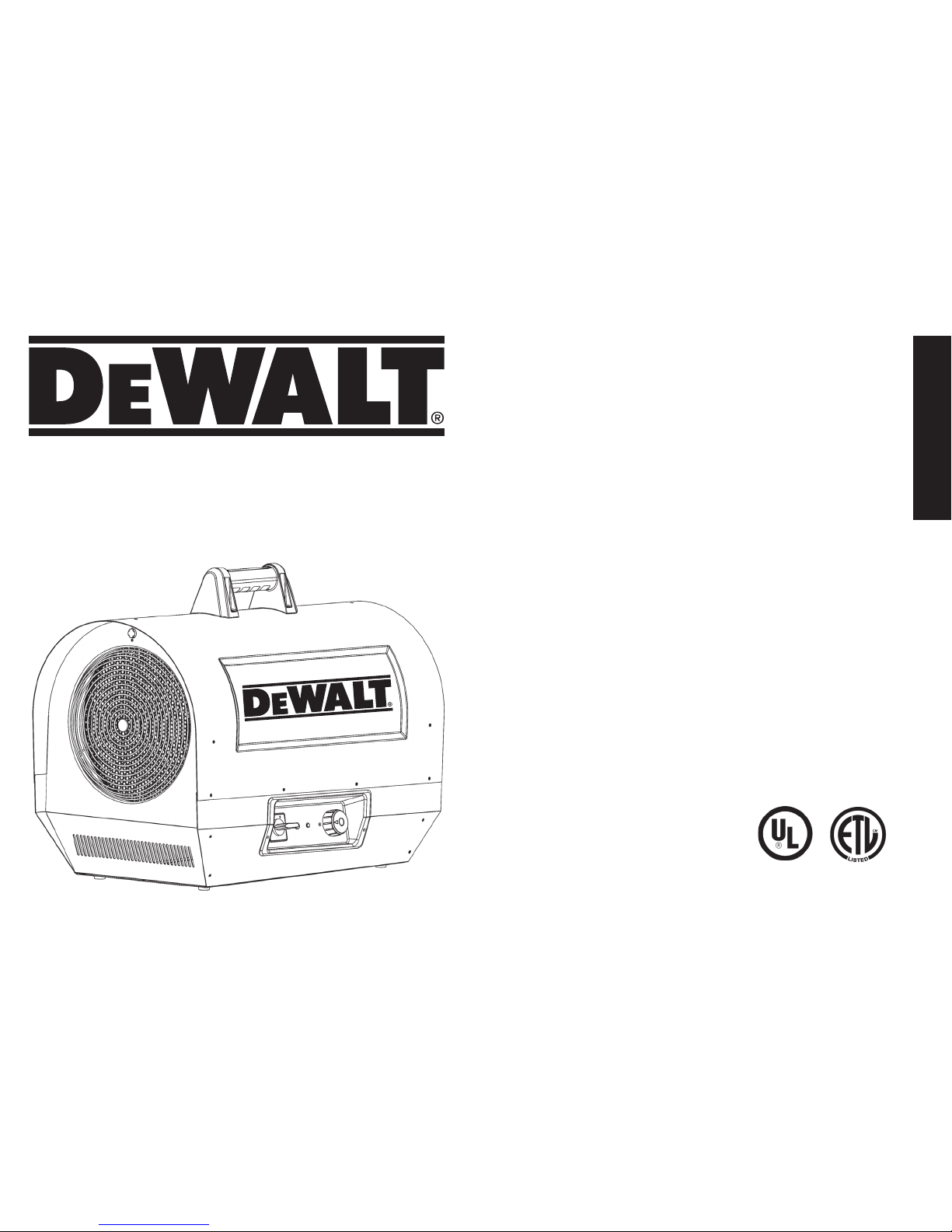
Electric Forced Air Heater DXH2000TS and DXH2003TS
Chauffage électrique à air forcé DXH2000TS and DXH2003TS
Calentador eléctrico de aire forzado DXH2000TS and DXH2003TS
7/13 41002 Rev13A
READ INSTRUCTIONS CAREFULLY: Read
and follow all instructions. Place instructions
in a safe place for future reference. Do
not allow anyone who has not read these
instructions to assemble, adjust or operate
the heater.
VEUILLEZ LIRE ATTENTIVEMENT LES INSTRUCTIONS :
Lisez et observez toutes les instructions. Conservez
ces instructions dans un endroit sécuritaire pour vous
y référer ultérieurement. Interdisez à quiconque n’ayant
pas lu les présentes directives d’assembler, de régler ou
de faire fonctionner cette fournaise.
LEA CUIDADOSAMENTE LAS INSTRUCCIONES:
Lea y siga todas las instrucciones. Conserve
estas instrucciones en un lugar seguro para futura
referencia. No permita que nadie que no haya
leído estas instrucciones arme, ajuste o use el
calentador.
Page 2
English
2
Definitions: Safety Guidelines
The denitions below describe the level of severity for each signal word. Please read the manual and pay attention to these symbols.
DANGER: Indicates an imminently hazardous situation which, if not avoided, will result in death or serious injury.
WARNING: Indicates a potentially hazardous situation which, if not avoided, could result in death or serious injury.
CAUTION: Indicates a potentially hazardous situation which, if not avoided, may result in minor or moderate injury.
NOTICE: Indicates a practice not related to personal injury which, if not avoided, may result in property damage.
WARNING: Do not use the heater if the unit, plug or cord has
visible damage or the unit has malfunctioned. Contact a reputable
electrician before reusing.
WARNING: Do not expose to wet conditions; unit is intended
for indoor use only.
WARNING: Unit not intended for use in indoor areas where
heater may be exposed to water. Avoid use in bathrooms, laundry
rooms or any other areas where the unit may come in contact with
water.
WARNING: Do not insert or allow any foreign objects to enter
the unit via the intake or exhaust vents on the unit. Failure to
observe this warning may result in electric shock, re or damage to
the unit.
WARNING: To prevent re do not block either the air intake or
exhaust.
WARNING: Unit is equipped with internal active electrical
components that spark during use. Do not use in areas where
fumes from gasoline, paint or other ammable liquids may be
present.
WARNING: Extreme caution must be used when any heater is
used by or near children or invalids and whenever the heater is left
operating and unattended.
SAVE THESE INSTRUCTIONS.
WARNING: DO NOT OPERATE THIS HEATER UNTIL YOU READ
AND UNDERSTAND THIS INSTRUCTION MANUAL FOR SAFETY,
OPERATION, AND MAINTENANCE INSTRUCTIONS.
CAUTION: Use of this heater in any means not described in this manual
may cause re, electric shock, personal injury and/or property damage.
CAUTION: This heater is hot when in use. To avoid burns,
do not let bare skin touch hot surfaces. Keep combustible materials, such
as furniture, pillows, bedding, papers, clothes, and curtains at least 6 feet
( 1.8 m) from the front of the heater and keep them at least 2 feet (.6 m)
away from the sides and rear
CAUTION: In order to avoid unintended cycling of the heater, always
unplug or disconnect unit from power source when not in use.
CAUTION: Do not cover the power supply wiring or run the wiring under
any carpet or rugs. Arrange cord and connections away from trafc patterns
so it is not a tripping hazard.
CAUTION: Connect unit to only properly grounded outlets and
adequately sized and grounded electrical systems.
CAUTION: Do not use this unit with unapproved or under sized electrical
connections or wiring. They may overheat and cause a risk of re.
Page 3

English
3
CONTENTS
WARNINGS ........................................................................... 2
ASSEMBLY ............................................................................ 3
OPERATION ........................................................................ 3-4
SPECIFICATIONS .................................................................. 4
CLEARANCES ....................................................................... 4
MAINTENANCE ..................................................................... 4
TROUBLESHOOTING .......................................................... 5
WIRING DIAGRAMS .............................................................. 6
PARTS LISTS/EXPLODED VIEWS .................................... 7-10
WARRANTY ......................................................................... 11
INSTRUCTIONS FOR ORDERING PARTS .......................... 11
Assembly
• Remove the heater and all of the packaging material from the box.
• Check all of the packing material for loose parts and set aside.
• Remove and retain the four handle mounting screws that are threaded into the
top shell.
• Throughly inspect the heater for damage. If any is found do not contact the place
of purchase. Please call the Manufacturer at 855-805-5745.
• Use the four handle mounting screws to fasten the handle to the top of the heater
Note: Do not over tighten the screws as they can crack the handle.
The handle is located in the carton loose be sure not to throw out.
Operational Information
The DeWalt Electric forced air heaters are designed to be used by professionals.
Heat is created by electric current passing through coiled metal elements bringing them up to very high temperatures. The fan then passes room air over the hot elements
exchanging cold air for warm.
The air moving over the coils keeps them from reaching temperatures that are not safe for the normal operation of the heater. However it is important to keep all combustible
materials and any objects that may be sucked into the fan blades at a safe distance (please refer to the table on the next page for appropriate distances). Make sure that the fan
blades remain unobstructed at all times.
Keep unit clean and dust free. Do not block unit intake or exhaust at any time.
Review and understand all warnings in this manual. Follow all local codes. These heaters are designed to be used with 240v ac only.
This heater must be wired by a certied electrician.
Operation
Page 4

English
4
ON/OFF HEAT ON INDICATOR LIGHT THERMOSTAT
WARNING:
Never attempt to service the heater while the unit is hot, In use, or plugged in. Only
qualified service technicians should service these units.
• Thoroughly inspect the unit prior to use.
• Keep heater clean and free of dust and debris.
• The use of an air compressor can be used to blow out the dust from the heater
case.
Be sure to only use moderate air pressure as to not damage any
internal components.
Starting Instructions, After Heater
Has Been Professionally Wired
1. Place the heater on a stable and level surface. Insure clearance to
combustibles are observed (see table on this page).
2. Turn thermostat counter-clockwise to lowest setting.
3. Move 4 way selector switch from the off position to the fan position for fan only
operation.
4. Move the selector switch to the 13kW position for partial power operation. The
partial power input requirement for the DXH2000TS is 240Vac/54A which
requires the use of a 60A/2 pole circuit breaker. The partial power input
requirement for the DXH2003TS is 240Vac/33A which requires the use of a
40A/3 pole circuit breaker.
5.
Turn thermostat knob up (clockwise) until desired temperature setting is reached.
6. Move the selector switch to the 20kW position for full power operation. The
full power input requirement for the DXH2000TS is 240Vac/81A which requires
the use of a 100A/2 pole circuit breaker. The full power requirement for the
DXH2003TS is 240Vac/50A which requires a 60A/3 pole circuit breaker.
7. The heating element and fan will remain on until the temperature setting is
reached. The heating element will cycle on and off as needed. The fan will remain
on as long as the control switch is in the on position.
To Stop Heating
Rotate the 4 way selector switch to the fan position for cool down. When the unit
is cool move the selector switch to the off position.
NOTE: This heater is equipped with an overheat limit switch which may cause the
heater to stop.This is indicated by a visual alarm when the power switch is in the
on position and all lights are off. (g 1) Check and remove the cause of the
overheating before restarting. This can take up to 15 minutes to cool before it
can be restarted.
Maintenance
• A soft dry cloth should be used for cleaning of outer shell and handle.
• The fan motor is sealed and does not need to be lubricated.
Specifications
Model: DXH2000 DXH2003P
Heat Output BTU/WATTS
44,357/13kW - 68,242/20kW 44,357/13kW - 68,242/20kW
Airflow (CFM) 725 725
Electrical Supply 240Vac 240Vac
Minimum Breaker Required
60A/2 Pole/Low - 100A/2 Pole/Hi 40A/3 Pole/Low - 60A/3 Pole/Hi
Amps
54/81
33/50
Thermostat
23°F - 95°F 23°F - 95°F
Dimensions: (L”xW”xH”) 27”x15”x18” 27”x15”x18”
Weight (lbs.) 49 lb. 49 lb.
Clearance to Combustibles
Outlet (Feet) 6 (1.8m)
Rear (Feet) 2 (.6m)
Top (Feet) 2 (.6m)
Bottom Non-combustible floor
FIG. 1
Fan indicator light is on when circulation fan is operating.
Page 5
English
5
Storage
When not in use, the heater must be disconnected from power source, dusted off
and the cord should be loosely wound around the handle.
For service :
Please call Toll-Free 855-805-5745 www.dewalt.com
Our office hours are 8:30 AM – 5:00 PM, EST, Monday through Friday.
Please include the model number, date of purchase, and description of problem in all
communication.
WARNING: USE ONLY MANUFACTURER’S REPLACEMENT PARTS. USE OF ANY OTHER PARTS COULD CAUSE INjURY OR
DEATH. REPLACEMENT PARTS ARE ONLY AVAILABLE DIRECT FROM THE FACTORY AND MUST BE INSTALLED BY A qUALIFIED
SERVICE AGENCY.
Troubleshooting
Unit does not work • Defective thermostat or wrong thermostat setting
• Open circuit breaker or fuse
• Thermal overload switch has been tripped
• Faulty Connection
• Damaged or defective plug or outlet
Unit runs continuously • Defective thermostat or wrong thermostat setting
• Heat losses higher than unit capacity (unit undersized)
Elements are on but motor does not rotate • Defective Motor
• Blocked fan blades
Enclosure is extremely hot • Defective thermal protection
• Blocked air vents
• Defective motor
Desired room temperature cannot be reached • One or more elements are defective
• Defective thermostat or wrong thermostat setting
• Voltage lower than that written on Rate tag
• Heat losses higher than unit capacity (unit undersized)
Overheating • Defective thermostat or wrong thermostat setting
• Defective Motor
Heater emits a humming sound • Defective motor
• Fan blade blocked
Note: Your heater is equipped with auto cool down and warm-up features.
AUTO COOLDOWN.
When the heater is running and the selector switch is rotated to the off position,
the heater will automatically keep the fan operating until the heater is cool. The
fan will then shut off.
AUTO WARM-UP.
When the heater is stored or started in very cold conditions and a heating mode
is selected, the heating element will turn on to warm up the unit before the fan
will start to blow hot air.
Page 6
English
6
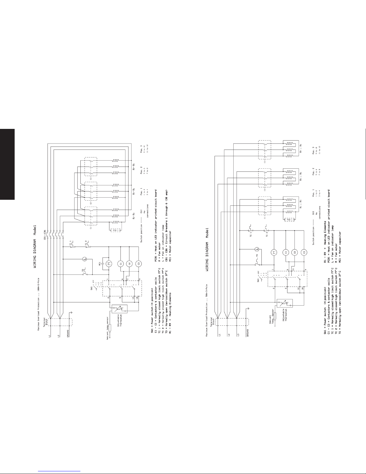
Wiring Diagrams
DXH2000TS
DXH2003TS
Page 7

English
7
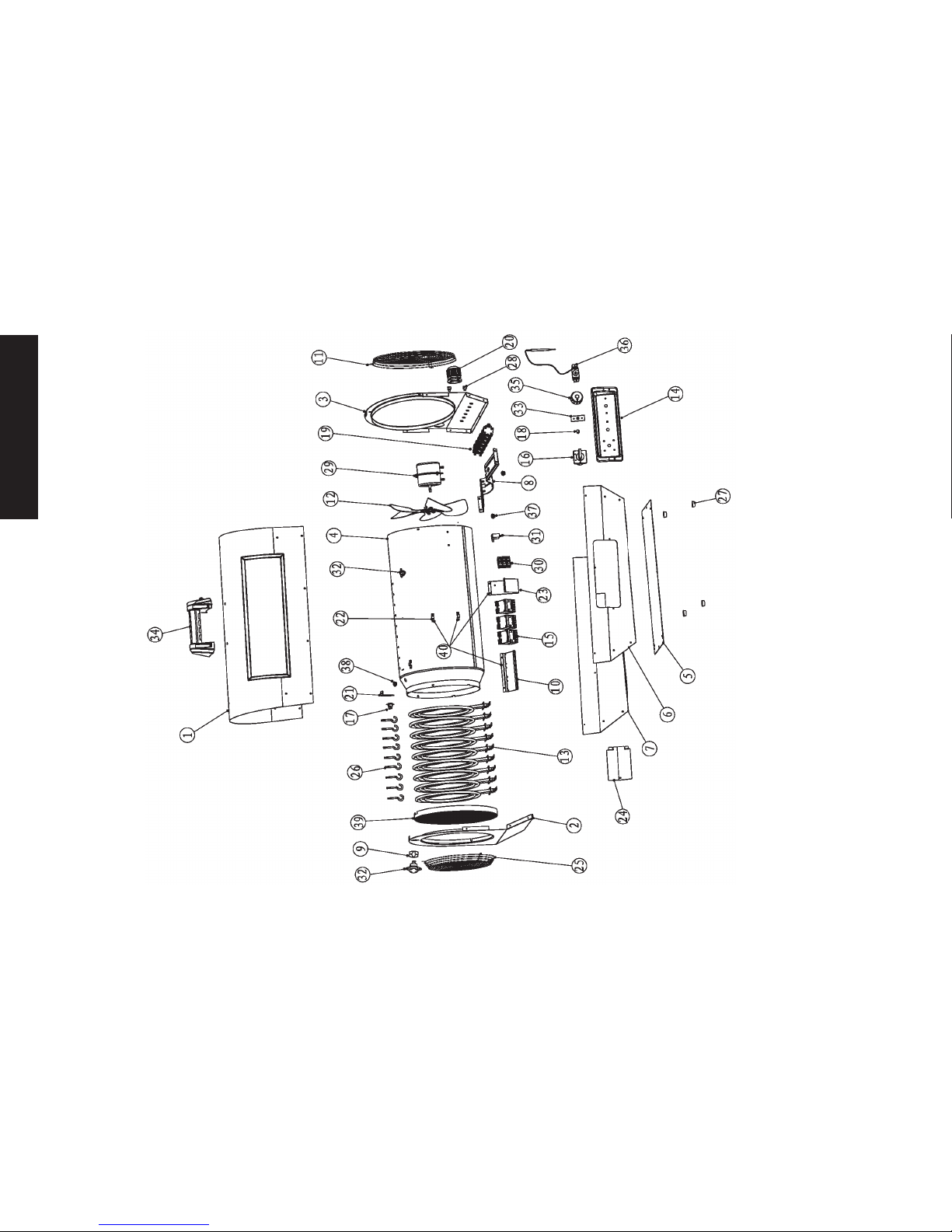
Parts List DXH2000TS
R E F. # ..............ITEM#............ DESCRIPTION
1 ...................... 41072 .............. COVER, TOP, SHELL, OUTER
2......................41073 .............. PANEL, FRONT
3
......................41074 .............. PANEL, REAR
4
......................41075 .............. SHIELD, RADIATION, TUBE
5
......................41076 .............. BASE, PLATE
6......................41077 ............. PANEL, SIDE, LEFT
7
......................41078 .............. PANEL, SIDE, RIGHT
8
......................41079 .............. BRACKET, MOUNT, MOTOR
9
......................41080 ............. BRACKET, SWITCH, HIGH LIMIT
10 .................... 410 81 ............
BRACKET, CONTACTOR, ELEMENT, HEATING
11
....................410 82 ............. GUARD, GRILL, REAR
12
.................... 41083 ............. BLADE, FAN
13 .................... 41084 ............. ELEMENT, HEATING
14 .................... 41085 ............. PANEL, CONTROL, PLASTIC
15 .................... 41086 ............. CONTACTOR, ELEMENT, HEATING
16
.................... 410 87 ............. SWITCH, MAIN, 4, POSITION
17
.................... 41088 ............. SWITCH, FAN, COOLDOWN, 37C
18 .................... 41089 ............. INDICATOR, FAN ON
19
.................... 41090 ............. BREAKER, CIRCUIT, 30AMP
20 .................... 410 91 .............. BUSHING, STRAIN, RELIEF
R E F. # ..............ITEM#............ DESCRIPTION
21 .................... 41092 ............. BRACKET, SWITCH, FAN, COOLDOWN
22 .................... 41028 ............. BRACKET, WIRE MOUNT
23
.................... 41093 ............. BRACKET, BLOCK, TERMINAL, WIRING
24
.................... 410 51 .............. DOOR, ACCESS
25
.................... 41064 ............. GUARD, GRILL, FRONT
26
.................... 4102 9 ............. SUPPORT, HEATING ELEMENT
27
.................... 41030 ............. FOOT, RUBBER
28
.................... 41031 .............. CLIP, SENSOR, CAPILLARY TUBE
29
.................... 410 67 ............. MOTOR, FAN
30
....................41094 ............. BLOCK, TERMINAL, WIRING
31 .................... 41070 .............. CAPACITOR, MOTOR, STARTER
32
.................... 41032 ............. SWITCH, HIGH LIMIT, 77C
33
....................41053 ............. BOARD, CIRCUIT, HEAT ON,INDICATOR
34
....................410 95 ............. HANDLE, CARRY
35....................410 27 ............. KNOB, THERMOSTAT, PLASTIC
36
.................... 41034 ............. THERMOSTAT, TEMPERATURE, AMBIANT
37
.................... 410 36 ............. BUSHING, PLASTIC, WIRE
38
....................41096 ............. BUSHING, PLASTIC, WIRE
39 ....................410 81 .............. FRONT SCREEN ASSEMBLY
40
....................4110 0 .............. RADIATION SHIELD TUBE W/BRACKETS
WARNING:
Use only manufacturer’s replacement parts. Use of any other parts could cause injury
or death. Replacement parts are only available direct from the factory and must be
installed by a qualified service agency.
For Service
Please call Toll-Free 855-805-5745 www.dewalt.com
Our office hours are 8:30 AM – 5:00 PM, EST, Monday through Friday.
Please include the model number, date of purchase, and description of problem in
all communication.
Page 8
English
8
DXH2000TS
Page 9

9
English
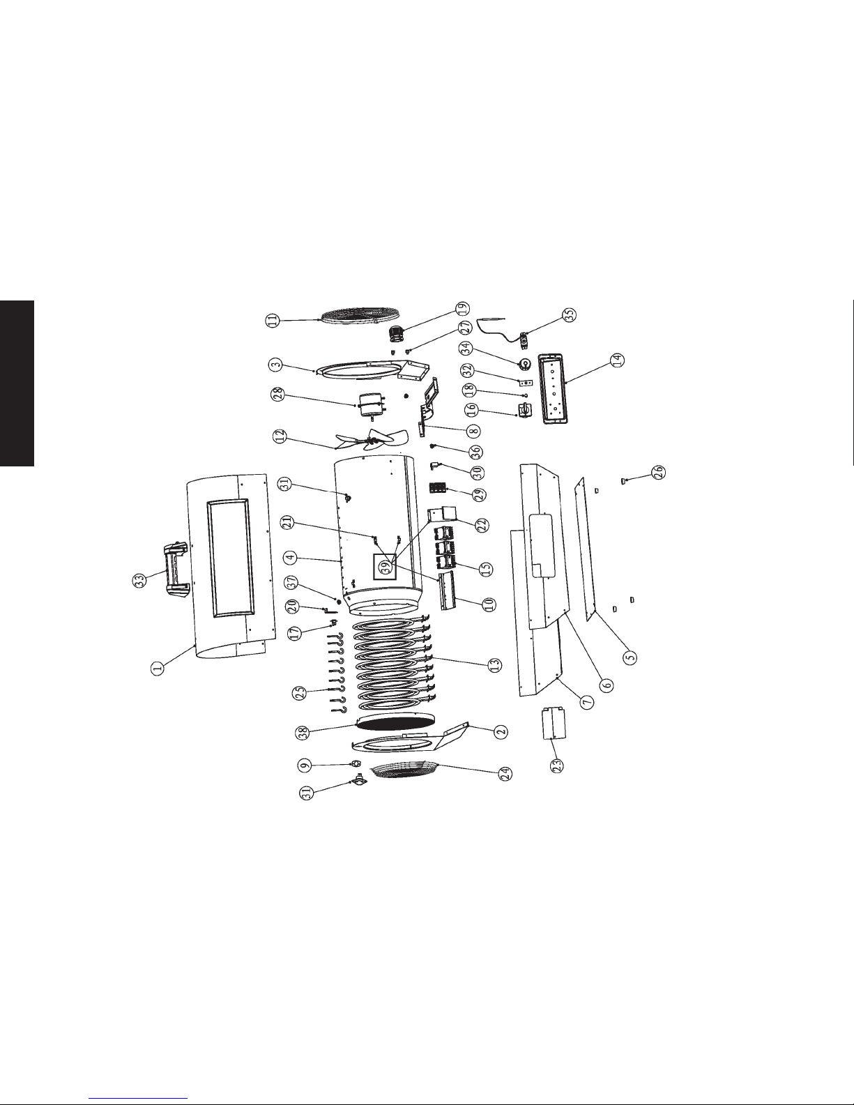
Parts List DXH2003TS
R E F. # ..............ITEM#............ DESCRIPTION
1 ...................... 41072 .............. COVER, TOP, SHELL, OUTER
2......................41073 .............. PANEL, FRONT
3
......................41074 .............. PANEL, REAR
4
......................41075 .............. SHIELD, RADIATION, TUBE
5
......................41076 .............. BASE, PLATE
6......................41077 ............. PANEL, SIDE, LEFT
7
......................41078 .............. PANEL, SIDE, RIGHT
8
......................41079 .............. BRACKET, MOUNT, MOTOR
9
......................41080 ............. BRACKET, SWITCH, HIGH LIMIT
10 .................... 410 81 ..............
BRACKET, CONTACTOR, ELEMENT, HEATING
11 ....................410 82 ............. GUARD, GRILL, REAR
12
.................... 41083 ............. BLADE, FAN
13
.................... 41084 ............. ELEMENT, HEATING
14 .................... 41085 ............. PANEL, CONTROL, PLASTIC
15 .................... 41086 ............. CONTACTOR, ELEMENT, HEATING
16
.................... 410 87 ............. SWITCH, MAIN, 4, POSITION
17
.................... 41088 ............. SWITCH, FAN, COOLDOWN, 37C
18
.................... 41089 ............. INDICATOR, FAN ON
19 .................... 410 91 .............. BUSHING, STRAIN, RELIEF
R E F. # ..............ITEM#............ DESCRIPTION
20 .................... 410 9 2 ............. BRACKET, SWITCH, FAN, COOLDOWN
21
.................... 41028 ............. BRACKET, WIRE MOUNT
22
.................... 41093 ............. BRACKET, BLOCK, TERMINAL, WIRING
23
.................... 410 51 .............. DOOR, ACCESS
24
.................... 41064 ............. GUARD, GRILL, FRONT
25
.................... 41029 ............. SUPPORT, HEATING ELEMENT
26
.................... 41030 ............. FOOT, RUBBER
27
.................... 410 31 .............. CLIP, SENSOR, CAPILLARY TUBE
28
.................... 41067 ............. MOTOR, FAN
29
.................... 41101 .............. BLOCK, TERMINAL, WIRING
30....................41070 .............. CAPACITOR, MOTOR, STARTER
31
.................... 41032 ............. SWITCH, HIGH LIMIT, 77C
32
.................... 41053 ............. BOARD, CIRCUIT, HEAT ON, INDICATOR
33
....................410 95 ............. HANDLE, CARRY
34....................410 27 ............. KNOB, THERMOSTAT, PLASTIC
35
....................41034 ............. THERMOSTAT, TEMPERATURE, AMBIANT
36
.................... 410 3 6 ............. BUSHING, PLASTIC, WIRE
37
.................... 41096 ............. BUSHING, PLASTIC, WIRE
38....................410 81 .............. FRONT SCREEN ASSEMBLY
39
.................... 4110 0 .............. RADIATION SHIELD TUBE W/BRACKETS
WARNING:
Use only manufacturer’s replacement parts. Use of any other parts could cause injury
or death. Replacement parts are only available direct from the factory and must be
installed by a qualified service agency.
For Service
Please call Toll-Free 855-805-5745 www.dewalt.com
Our office hours are 8:30 AM – 5:00 PM, EST, Monday through Friday.
Please include the model number, date of purchase, and description of problem in
all communication.
Page 10
English
10
DXH2003TS
Page 11
11
English
INSTRUCTION MANUAL
Electric Forced-Air Heater DXH2000TS, DXH2003TS
PARTS ORDERING INFORMATION:
Use only manufacturer’s replacement parts. Use of any other parts could cause
injury or death. Replacement parts are only available direct from the factory and
must be installed by a qualified service agency.
Warning:
PURCHASING: Accessories may be purchased at any DeWalt® local
dealer or direct from the factory
FOR INFORMATION REGARDING SERVICE:
Please call Toll-Free 855-805-5745
www.dewalt.com
Our office hours are 8:30 AM – 5:00 PM, EST, Monday through Friday.
Please include the model number, date of purchase, and description of
problem in all communication.
LIMITED WARRANTY:
DeWalt® warrants its heaters and accessories to be free from defects in
material and workmanship for a period of 1 year from date of purchase.
DeWalt® will repair or replace this product free of charge if it has been
proven to be defective within the 1-year period, and is returned at customer
expense with proof of purchase to DeWalt® within the warranty period.
U.L. 2021 CSA C22.2#46
Model Starting Serial Number
DXH2000 LN-340650-13001001
DXH2003P LN-340655-13001001
DEWALT®, GUARANTEED TOUGH® and the
yellow and black color scheme are trademarks
of the DEWALT Industrial Tool Co., used under
license. ©2013 DEWALT. EGI/Enerco Group Inc.
Under license from Dewalt Industrial Tool Co.
Page 12

Page 13

7/13 41002 Rev13A
If you have questions or comments, contact us.
Si vous avez des questions ou commentaires, veuillez nous contacter. Llámenos si tiene alguna pregunta o comentario.
INSTRUCTION MANUAL
MANUEL D’INSTRUCTIONS
MANUAL DE INSTRUCCIONES
READ INSTRUCTIONS CAREFULLY: Read
and follow all instructions. Place instructions
in a safe place for future reference. Do
not allow anyone who has not read these
instructions to assemble, adjust or operate
the heater.
VEUILLEZ LIRE ATTENTIVEMENT LES INSTRUCTIONS :
Lisez et observez toutes les instructions. Conservez
ces instructions dans un endroit sécuritaire pour vous
y référer ultérieurement. Interdisez à quiconque n’ayant
pas lu les présentes instructions d’assembler, d’ajuster
ou de faire fonctionner l’appareil de chauffage.
855-805-5745 • www.dewalt.com
Electric Forced Air Heater DXH2000TS and DXH2003TS
Appareil de chauffage à air forcé électrique modèles DXH2000TS et DXH2003TS
Calentador eléctrico a aire forzado DXH2000TS y DXH2003TS
LEA CUIDADOSAMENTE LAS INSTRUCCIONES:
Lea y siga todas las instrucciones. Conserve
estas instrucciones en un lugar seguro para futura
referencia. No permita que nadie que no haya
leído estas instrucciones arme, ajuste o use el
calentador.
Page 14

Français
2
AVERTISSEMENT : N’utilisez pas l’appareil de chauffage si
celui-ci, la che ou le cordon a des dommages visibles ou si l’appareil
a mal fonctionné. Avant d’utiliser de nouveau l’appareil, veuillez
communiquer avec un électricien qualié.
AVERTISSEMENT :
N’exposez pas l’appareil à des conditions
d’humidité; cet appareil est conçu seulement pour une utilisation à l’intéri.
AVERTISSEMENT : L’appareil n’est pas conçu pour être utilisé
dans des zones à l’intérieur où il peut être exposé à de l’eau. Évitez
de l’utiliser dans les salles de bain, les buanderies, ou toute autre
zone où l’appareil peut entrer en contact avec de l’eau.
AVERTISSEMENT :
N’insérez ni ne permettez à aucun objet
étranger d’entrer dans l’appareil par le biais de l’entrée ou de la sortie
d’air de l’appareil. Un non-respect de cet avertissement peut provoquer
une décharge électrique, un incendie ou des dommages à l’appareil.
AVERTISSEMENT : Pour empêcher tout incendie, ne bloquez ni
l’entrée ni la sortie d’air.
AVERTISSEMENT :
L’appareil est équipé avec des composants
électriques internes actifs qui produisent des étincelles lors de son
utilisation. Ne l’utilisez pas dans des zones où des émanations d’essence,
de peinture ou d’autres liquides inammables peuvent s’y trouver.
AVERTISSEMENT : Une étroite surveillance est requise lorsque
tout appareil de chauffage est utilisé par ou près des enfants ou des
personnes handicapées et lorsque l’appareil est laissé en opération
et sans surveillance.
CONSERVEZ CES INSTRUCTIONS.
AVERTISSEMENT : NE FAITES PAS FONCTIONNER CET
APPAREIL DE CHAUFFAGE JUSQU’À CE QUE VOUS AYEZ LU ET
COMPRIS CE MANUEL D’INSTRUCTIONS POUR LES DIRECTIVES
DE SÉCURITÉ, DE FONCTIONNEMENT ET D’ENTRETIEN.
MISE EN GARDE : L’utilisation de cet appareil de chauffage de toute
autre façon que celle décrite dans ce manuel peut provoquer un incendie,
une décharge électrique, des blessures personnelles et/ou aux biens.
MISE EN GARDE : Cet appareil devient chaud lorsqu’utilisé. Pour éviter
les brûlures, évitez que la peau touche aux surfaces chaudes. Gardez les
produits combustibles, tels que les meubles, les oreillers, la literie, les papiers,
les vêtements et les rideaux, à au moins 1,8 m (6 pi) du devant de l’appareil
de chauffage et gardez-les à au moins 0,6 m (2 pi) des côtés et de l’arrière.
MISE EN GARDE :
An d’éviter tout cycle inattendu de l’appareil de
chauffage, toujours le débrancher ou le déconnecter de la source d’alimentation
lorsque vous ne l’utilisez pas.
MISE EN GARDE :
Ne recouvrez pas le câblage de l’alimentation ni ne le
faites courir sous tout tapis ou carpette. Placez le cordon d’alimentation et les
branchements loin des zones de circulation, de sorte qu’ils ne deviendront pas un
risque de trébuchement.
MISE EN GARDE : Branchez l’appareil à des prises de courant
correctement mises à la terre et de la bonne grandeur, ainsi qu’à des
systèmes électriques mis à la terre.
MISE EN GARDE : N’utilisez pas l’appareil avec des connexions ou des
câblages électriques non approuvés ou trop petits. Ils peuvent surchauffer et
provoquer un risque d’incendie.
Définitions : Directives de sécurité
Les dénitions ci-dessous décrivent le niveau de sévérité pour chaque mot signalétique. Veuillez lire le manuel et faire attention à ces symboles.
DANGER : Indique « une situation à risque imminent, laquelle, si elle n’est pas évitée, entraînera des blessures sérieuses ou la mort ».
AVERTISSEMENT :
Indique « une situation à risque potentiel, laquelle si elle n’est pas évitée, pourrait entraîner des blessures sérieuses ou la mort ».
MISE EN GARDE : Indique une situation dangereuse potentielle, laquelle, si elle n’est pas évitée, peut causer des blessures mineures ou des blessures légères.
AVIS : Indique une pratique non reliée à une blessure personnelle, laquelle, si elle n’est pas évitée, peut entraîner des dommages aux biens.
Page 15

Français
3
TABLE DES MATIÈRES
AVERTISSEMENT .................................................................. 2
ASSEMBLAGE ....................................................................... 3
FONCTIONNEMENT........................................................... 3-4
SPÉCIFICATIONS .................................................................. 4
ESPACES LIBRES ............................................................... 4
ENTRETIEN ........................................................................... 4
GUIDE DE DÉPANNAGE ....................................................... 5
SCHÉMAS DU CÂBLAGE ..................................................... 6
LISTES DES PIÈCES/VUES ÉCLATÉES ........................... 7-10
GARANTIE ........................................................................... 11
INSTRUCTIONS POUR COMMANDER DES PIÈCES ......... 11
Assemblage
• Enlevez l’appareil de chauffage et tout le matériel d’emballage de la boîte.
• Vérifiez l’ensemble du matériel d’emballage pour toute pièce mobile et mettez-les
de côté.
• Enlevez et mettez de côté les quatre vis de montage de la poignée qui sont filetées
dans la coque supérieure.
• Inspectez à fond l’appareil de chauffage pour en déceler tout dommage. Si vous
en trouvez, ne communiquez pas avec le lieu d’achat. Communiquez plutôt avec le
fabricant au 855-805-5745.
• Utilisez les quatre vis de montage de la poignée pour fixer cette dernière au haut
de l’appareil de chauffage.
Remarque : Ne pas trop serrer les vis car cela peut fissurer la poignée.
La poignée est située dans le matériel d’emballage de la boîte; assurez-vous de ne
pas la jeter.
Information sur le fonctionnement
Les appareils de chauffage à air forcé électriques DeWalt sont conçus pour être utilisés par des professionnels.
La chaleur est créée par un courant électrique passant à travers des éléments métalliques spiralés, les chauffant à de très fortes températures. Le ventilateur fait courir l’air de la
pièce sur les éléments chauds, échangeant ainsi l’air froid en de l’air chaud.
L’air se déplaçant sur les spirales les empêche d’atteindre des températures dangereuses pour le fonctionnement normal de l’appareil de chauffage. Cependant, il est important
de garder tout matériel combustible et tout objet qui peuvent être aspirés dans les pales du ventilateur à une distance sécuritaire (veuillez vous référer à la table à la page
suivante pour les distances appropriées). Assurez-vous que les pales du ventilateur demeurent dégagées en tout temps.
Gardez l’appareil propre et libre de poussières. Ne jamais bloquer l’entrée ou la sortie de l’appareil.
Révisez et comprenez l’ensemble des avertissements dans ce manuel. Suivez tous les codes locaux. Ces appareils de chauffage sont conçus pour utilisation avec une tension de 240
VCA uniquement.
Cet appareil de chauffage doit être câblé par un électricien qualifié.
Fonctionnement
Page 16

Français
4
MARCHE/ARRÊT INDICATEUR DU CHAUFFAGE EN MARCHE THERMOSTAT
AVERTISSEMENT :
N’essayez jamais de faire l’entretien de l’appareil de chauffage s’il est chaud, en utilisation ou
branché. Seuls des techniciens qualifiés devraient faire l’entretien de ces appareils.
• Veuillez toujours inspecter l’appareil avant de l’utiliser.
• Gardez l’appareil propre et libre de poussières et de débris.
•
Vous pouvez utiliser de l’air comprimé pour souffler la poussière du bâti de l’appareil de chauffage.
Assurez-vous de seulement utiliser une pression d’air modérée afin de ne pas
endommager les composants internes.
Instructions de démarrage, après que l’appareil
de chauffage ait été câblé professionnellement
1. Placez l’appareil sur une surface plane et à niveau. Assurez-vous que l’espace libre entre tout
combustible soit respecté (voir la table sur cette page).
2. Tournez le thermostat dans le sens contraire des aiguilles d’une montre à sa plus basse position.
3. Déplacez le commutateur du sélecteur à 4 voies de la position « fermée » à la position « ventilation »
pour tout fonctionnement seul du ventilateur.
4. Déplacez le commutateur du sélecteur à la position 13kW pour un fonctionnement avec une tension
partielle. Les exigences de l’entrée de tension partielle pour le modèle DXH2000TS sont de 240
VCA/54 A, ce qui demandent l’utilisation d’un disjoncteur bipolaire de 60 A. Les exigences de l’entrée
de tension partielle pour le modèle DXH2003TS sont de 240 VCA/33A, ce qui demandent l’utilisation
d’un disjoncteur tripolaire de 40A.
5. Tournez le bouton du thermostat vers le haut (dans le sens horaire) jusqu’à ce que la température
désirée soit atteinte.
6. Déplacez le commutateur du sélecteur à la position 20kW pour un fonctionnement avec une tension
complète. Les exigences de l’entrée de tension complète pour le modèle DXH2000TS sont de 240
VCA/81A, ce qui demandent l’utilisation d’un disjoncteur bipolaire de 100A. Les exigences de l’entrée
de tension complète pour le modèle DXH2003TS sont de 240 VCA/50A, ce qui demandent l’utilisation
d’un disjoncteur tripolaire de 60A.
7.
L’élément chauffant et le ventilateur demeureront allumés jusqu’à ce que la configuration pour la température
soit atteinte. L’élément de chauffage va effectuer un cycle de marche et d’arrêt si besoin est. Le ventilateur
demeurera allumé aussi longtemps que le commutateur de contrôle est en position « marche ».
Pour fermer le chauffage
Tournez le commutateur du sélecteur à 4 positions à la position « ventilation » pour refroidir.
Lorsque l’appareil est refroidi, déplacez le commutateur du sélecteur à la position « fermé »
REMARQUE : Cet appareil de chauffage est équipé avec un commutateur de limite
de surchauffe qui peut provoquer l’arrêt de l’appareil. C’est indiqué par une alarme
visuelle lorsque le commutateur de tension est en position « en marche » et que tous les
indicateurs soient éteints. (gure 1) Vériez et enlevez la cause de la surchauffe avant de
redémarrer l’appareil. L’appareil peut prendre jusqu’à 15 minutes à se refroidir avant de
redémarrer.
Entretien
• Un doux chiffon sec devrait être utilisé pour nettoyer l’enceinte extérieure et la poignée.
• Le moteur du ventilateur est scellé et n’a pas besoin d’être lubrifié.
Modèle
: DXH2000 DXH2003P
Sortie de la chaleur BTU/WATTS
44357/13kW - 68242/20kW 44357/13kW - 68242/20kW
Flux d’air 725 pi3/mn 725 pi3/mn
Alimentation électrique 240 V CA 240 V CA
Disjoncteur min. requis
60A/Bipolaire/Bas - 100A/Bipolaire/Haut 40A/Tripolaire/Bas - 60A/Tripolaire/Haut
Courant
54/81 A
33/50 A
Thermostat
-5 °C - 35 °C -5 °C - 35 °C
Dimensions : (LxlxH) 68,6 x 38,1 x 45,7 cm 68,6 x 38,1 x 45,7 cm
Poids 22,2 Kg 22,2 Kg
Espace libre entre tout matériel combustible
Sortie 1,8 m
Arrière 0,6 m
Haut 0,6 m
Bas Plancher non-combustible
FIG. 1
L’indicateur du ventilateur est « en marche » lorsque le ventilateur de
circulation est en fonctionnement.
Spécifications
Page 17

Français
5
Entreposage
Lorsque l’appareil de chauffage n’est pas utilisé, il doit être débranché de la source
de tension, épousseté et le cordon doit être grossièrement enroulé autour de la
poignée.
Pour l’entretien :
Veuillez appeler sans frais le 855-805-5745 www.dewalt.com
Nos heures de bureau sont de 8 h 30 à 17 h, fuseau horaire de l’est, du lundi au vendredi.
Veuillez inclure le numéro du modèle, la date d’achat et la description du problème
lors de toute communication.
AVERTISSEMENT : N’UTILISEZ QUE LES PIÈCES DE REMPLACEMENT DU FABRICANT. L’UTILISATION D’AUTRES PIÈCES RISQUE DE CAUSER DES BLESSURES ET LA MORT. LES PIÈCES DE RECHANGE SONT SEULEMENT DISPONIBLES DIRECTEMENT
DE L’USINE ET DOIVENT ÊTRE INSTALLÉES PAR UNE ENTREPRISE DE SERVICE SPÉCIALISÉE.
Guide de dépannage
Remarque : Votre appareil de chauffage est équipé avec des options de refroidissement et de
chauffage automatiques.
REFROIDISSEMENT AUTOMATIQUE.
Lorsque l’appareil est en fonctionnement et que le commutateur du sélecteur est tourné à
la position « fermé », l’appareil de chauffage va automatiquement garder le ventilateur en
marche jusqu’à refroidissement de l’appareil de chauffage. Le ventilateur va alors s’arrêter.
CHAUFFAGE AUTOMATIQUE.
Lorsque l’appareil de chauffage est entreposé ou démarré dans des conditions très froides
et qu’un mode de chauffage est sélectionné, l’élément chauffant s’allumera pour réchauffer
l’appareil avant que le ventilateur commencer à soufer de l’air chaud.
L’appareil ne fonctionne pas • Thermostat défectueux ou mauvaise configuration du thermostat
• Disjoncteur ou fusible ouvert
• Le commutateur de surcharge thermique s’est déclenché
• Branchement défectueux
• Prise ou fiche endommagée ou défectueuse
L’appareil fonctionne sans arrêt • Thermostat défectueux ou mauvaise configuration du thermostat
•
Pertes de chaleur plus élevées que la capacité de l’appareil (l’appareil est sous-dimensionné)
Les éléments sont allumés mais le moteur ne tourne pas • Moteur défectueux
• Pales du ventilateur bloquées
L’enceinte est extrêmement chaude • Protection thermique défectueuse
• Évents d’air bloqués
• Moteur défectueux
La température désirée de la pièce ne peut pas être atteinte • Un élément, ou plus, est défectueux
• Thermostat défectueux ou mauvaise configuration du thermostat
• Tension plus basse que ce qui est indiquée sur l’étiquette du taux de tension
•
Pertes de chaleur plus élevées que la capacité de l’appareil (l’appareil est sous-dimensionné)
Surchauffe • Thermostat défectueux ou mauvaise configuration du thermostat
• Moteur défectueux
L’appareil émet un bourdonnement • Moteur défectueux
• Pale du ventilateur bloquée
Page 18

SCHÉMA DE CÂBLAGE MODÈLE DXH2000TS
Protection maximale contre les surcharges : 100 A/bipolaire
Bornier
Mise à
la terre
Sonde de température
ambiante
Thermostat
ajustable
Position du
commutateur
Arrêt
Nombre de
branchements
1 à 2
5 à 6
9 à 10
11 à 12
3 à 4
7 à 8
SW1 = Interrupteur d’alimentation (4 positions)
C1 - C3 = Contacteur et bobines du contacteur PCB1 = Circuit imprimé avec indicateur DEL « en marche »
TC 1 = Interrupteur de haute limite normalement fermé 77°C M = Moteur de ventilateur
TC 2 = Interrupteur de haute limite normalement fermé 77°C L = Lampe de l'indicateur du ventilateur « en marche »
TO = Commut. de refroid./ventilation norm. ouvert 37°C CB1 - CB6 = Disjoncteurs 1 à 6 (30 ampères)
R1 - R9 = Éléments chauffants MC1 = Condensateur du moteur
Protection maximale contre les surcharges : 50 A/bipolaire
SCHÉMA DE CÂBLAGE MODÈLE DXH2003TS
Bornier
Mise à
la
terre
Sonde de température
ambiante
Thermostat
ajustable
SW1 = Interrupteur d’alimentation (4 positions) R1 - R9 = Éléments chauffants
C1 - C3 = Contacteur et bobines du contacteur PCB1 = Circuit imprimé avec indicateur DEL « en marche »
TC 1 = Interrupteur de haute limite normalement fermé 77°C L = Lampe de l'indicateur du ventilateur « en marche »
TC 2 = Interrupteur de haute limite normalement fermé 77°C M = Moteur de ventilateur
TO = Commut. de refroid./ventilation norm. ouvert 37°C MC1 = Condensateur du moteur
Position du
commutateur
Arrêt
Nombre de
branchements
1 à 2
5 à 6
9 à 10
11 à 12
3 à 4
7 à 8
Français
6
Schémas du câblage
Page 19

Français
7
Liste des pièces DXH2000TS
RÉF. # .............ITEM#....... .... DESCRIPTION
1 ...................... 41072 .............. COUVERCLE, HAUT, COQUE, EXTÉRIEUR
2......................41073 .............. PANNEAU, AVANT
3
......................41074 .............. PANNEAU, ARRIÈRE
4
......................41075 .............. ÉCRAN, RADIATION, TUBE
5
......................41076 .............. BASE, PLAQUE
6......................41077 ............. PANNEAU, LATÉRAL, GAUCHE
7......................41078 .............. PANNEAU, LATÉRAL, DROIT
8
......................41079 .............. SUPPORT, MONTAGE, MOTEUR
9
......................41080 .............
SUPPORT, COMMUTATEUR, LIMITE ÉLEVÉE
10 .................... 410 81 ............
SUPPORT, CONTACTEUR, ÉLÉMENT, CHAUFFANT
11 ....................410 82 ............. GARDE, GRILLE, ARRIÈRE
12
.................... 41083 ............. PALE, VENTILATEUR
13 .................... 41084 ............. ÉLÉMENT, CHAUFFANT
14 .................... 41085 ............. PANNEAU, CONTRÔLE, PLASTIQUE
15 .................... 41086 ............. CONTACTEUR, ÉLÉMENT, CHAUFFANT
16
.................... 410 87 ............. COMMUTATEUR, PRINCIPAL, 4, POSITION
17
.................... 41088 .............
COMMUTATEUR, VENTILATEUR, REFROID., 37 ºC
18 .................... 41089 ............. INDICATEUR, VENTILATEUR EN MARCHE
19
.................... 41090 ............. DISJONCTEUR, CIRCUIT, 30 AMPÈRES
20 .................... 410 91 .............. BAGUE, TENSION, RÉDUCTEUR
RÉF. # .............ITEM#....... .... DESCRIPTION
21 .................... 41092 .............
SUPPORT, COMMUTATEUR, VENTILATEUR, REFROID.
22 ....................410 28 .............SUPPORT, MONTAGE SUR CÂBLE
23
.................... 41093 ............. SUPPORT, BORNIER, CÂBLAGE
24
.................... 410 51 .............. PORTE, ACCÈS
25
.................... 41064 ............. GARDE, GRILLE, AVANT
26 ....................410 29 ............. SUPPORT, ÉLÉMENT CHAUFFANT
27
.................... 41030 ............. PIED, CAOUTCHOUC
28
.................... 41031 .............. CLIP, SONDE, TUBE CAPILLAIRE
29
.................... 410 67 ............. MOTEUR, VENTILATEUR
30....................41094 ............. BORNIER, CÂBLAGE
31
.................... 41070 .............. CONDENSATEUR, MOTEUR, DÉMARREUR
32
.................... 41032 ............. COMMUTATEUR, LIMITE ÉLEVÉE, 77
ºC
33....................41053 .............
CIRCUIT IMPRIMÉ, CHALEUR ACTIVÉE, L’INDICATEUR
34
....................410 95 ............. POIGNÉE, TRANSPORT
35
....................410 27 ............. CONTROL, TERMOSTÁTICO, PLÁSTICO
36
.................... 41034 ............. BOUTON, THERMOSTAT, PLASTIQUE
37 .................... 410 36 ............. BAGUE, PLASTIQUE, CÂBLE
38
....................41096 ............. BAGUE, PLASTIQUE, CÂBLE
39 .................... 410 81 .............. ENSEMBLE ÉCRAN AVANT
40
....................4110 0 ..............
RAYONNEMENT TUBE DE PROTECTION AVEC SUPPORTS
AVERTISSEMENT :
N’utilisez que les pièces de remplacement du fabricant. L’utilisation d’autres pièces
risque de causer des blessures ou la mort. Les pièces de remplacement ne sont
offertes que par le fabricant et doivent être installées par une entreprise de service
spécialisée..
Pour l’entretien
Veuillez appeler sans frais le 855-805-5745 www.dewalt.com
Nos heures de bureau sont de 8 h 30 à 17 h, fuseau horaire de l’est, du lundi au
vendredi.
Veuillez inclure le numéro du modèle, la date d’achat et la description du problème
lors de toute communication.
Page 20

Français
8
DXH2000TS
Page 21

9
Français
Liste des pièces DXH2003TS
RÉF. # .............ITEM#....... .... DESCRIPTION
1 ...................... 41072 .............. COUVERCLE, HAUT, COQUE, EXTÉRIEUR
2......................41073 .............. PANNEAU, AVANT
3
......................41074 .............. PANNEAU, ARRIÈRE
4
......................41075 .............. ÉCRAN, RADIATION, TUBE
5......................41076 .............. BASE, PLAQUE
6
......................41077 ............. PANNEAU, LATÉRAL, GAUCHE
7
......................41078 .............. PANNEAU, LATÉRAL, DROIT
8
......................41079 .............. SUPPORT, MONTAGE, MOTEUR
9......................41080 .............
SUPPORT, COMMUTATEUR, LIMITE ÉLEVÉE
10 .................... 410 81 ..............
SUPPORT, CONTACTEUR, ÉLÉMENT, CHAUFFANT
11 ....................410 82 ............. GARDE, GRILLE, ARRIÈRE
12 .................... 41083 ............. PALE, VENTILATEUR
13
.................... 41084 ............. ÉLÉMENT, CHAUFFANT
14 .................... 41085 ............. PANNEAU, CONTRÔLE, PLASTIQUE
15 .................... 41086 ............. CONTACTEUR, ÉLÉMENT, CHAUFFANT
16 .................... 410 87 .............
COMMUTATEUR, PRINCIPAL, 4, POSITION
17 .................... 41088 .............
COMMUTATEUR, VENTILATEUR, REFROID., 37 ºC
18 .................... 41089 ............. INDICATEUR, VENTILATEUR EN MARCHE
19 .................... 410 91 .............. BAGUE, TENSION, RÉDUCTEUR
RÉF. # .............ITEM#....... .... DESCRIPTION
20 .................... 410 9 2 .............
SUPPORT, COMMUTATUR, VENTILATEUR, REFROID.
21 .................... 41028 ............. SUPPORT, MONTAGE DE CÂBLES
22
.................... 41093 .............
SUPPORT, BORNIER, CÂBLAGE
23 ....................410 51 .............. PORTE, ACCÈS
24
.................... 41064 ............. GARDE, GRILLE, AVANT
25 .................... 41029 ............. SUPPORT, ÉLÉMENT CHAUFFANT
26 .................... 41030 ............. PIED, CAOUTCHOUC
27 .................... 410 31 .............. CLIP, SONDE, TUBE CAPILLAIRE
28 .................... 41067 ............. MOTEUR, VENTILATEUR
29
.................... 41101 .............. BORNIER, CÂBLAGE
30....................41070 .............. CONDENSATEUR, MOTEUR, DÉMARREUR
31 .................... 41032 ............. COMMUTATEUR, LIMITE ÉLEVÉE, 77
ºC
32 .................... 41053 .............
CIRCUIT IMPRIMÉ, CHALEUR ACTIVÉE, INDICATEUR
33....................410 95 ............. POIGNÉE, TRANSPORT
34
....................410 27 ............. BOUTON, THERMOSTAT, PLASTIQUE
35....................41034 ............. THERMOSTAT, TEMPÉRATURE, AMBIANTE
36
.................... 410 3 6 ............. BAGUE, PLASTIQUE, CÂBLE
37 .................... 41096 ............. BAGUE, PLASTIQUE, CÂBLE
38....................410 81 .............. ENSEMBLE ÉCRAN AVANT
39
.................... 4110 0 ..............
RAYONNEMENT TUBE DE PROTECTION AVEC SUPPORTS
AVERTISSEMENT :
N’utilisez que les pièces de remplacement du fabricant. L’utilisation d’autres pièces
risque de causer des blessures ou la mort. Les pièces de remplacement ne sont
offertes que par le fabricant et doivent être installées par une entreprise de service
spécialisée..
Pour l’entretien
Veuillez appeler sans frais le 855-805-5745 www.dewalt.com
Nos heures de bureau sont de 8 h 30 à 17 h, fuseau horaire de l’est, du lundi au
vendredi.
Veuillez inclure le numéro du modèle, la date d’achat et la description du problème
lors de toute communication.
Page 22

Français
10
DXH2003TS
Page 23

11
Français
MANUEL D’INSTRUCTIONS
Appareil de chauffage à air forcé électrique modèles
DXH2000TS, DXH2003TS
U.L. 2021 CSA C22.2#46
Modèle Numéro de série de début
DXH2000 LN-340650-13001001
DXH2003P LN-340655-13001001
DEWALT®, GUARANTEED TOUGH® et les schémas
de couleurs jaune et noir sont des marques de
commerce de DEWALT Industrial Tool Co., utilisées
sous licence. ©2013 DEWALT. EGI/Enerco Group Inc.
sous licence de Dewalt Industrial Tool Co.
INFORMATION SUR LA COMMANDE DES PIÈCES :
N’utilisez que les pièces de remplacement du fabricant. L’utilisation d’autres
pièces risque de causer des blessures et la mort. Les pièces de remplacement
ne sont offertes que directement de l’usine et doivent être installées par une
entreprise de service spécialisée.
AVERTISSEMENT :
ACHAT : Les accessoires peuvent être achetés chez n’importe quel
revendeur local DeWalt® ou directement à l’usine.
POUR OBTENIR DES INFORMATIONS SUR LE SERVICE :
Appelez sans frais au 855-805-5745
www.dewalt.com
Nos heures de bureau sont de 8 h 30 à 17 h, HE, du lundi au vendredi.
Veuillez indiquer le numéro du modèle, la date d’achat et la description du
problème dans toutes vos communications.
GARANTIE LIMITÉE :
DeWalt® garantit ses appareils de chauffages et ses accessoires contre les
défauts de matériel et de main-d’œuvre pour une période d’un an à partir
de la date d’achat. DeWalt® réparera ou remplacera ce produit sans frais
s’il est démontré qu’il est devenu défectueux pendant la période d’un (1)
an et qu’il est retourné à DeWalt® aux frais de l’acheteur avec une preuve
d’achat, au cours de la période de garantie.
Page 24

Page 25

7/13 41002 Rev13A
If you have questions or comments, contact us.
Si vous avez des questions ou commentaires, veuillez nous contacter. Llámenos si tiene alguna pregunta o comentario.
INSTRUCTION MANUAL
MANUEL D’INSTRUCTIONS
MANUAL DE INSTRUCCIONES
READ INSTRUCTIONS CAREFULLY: Read
and follow all instructions. Place instructions
in a safe place for future reference. Do
not allow anyone who has not read these
instructions to assemble, adjust or operate
the heater.
VEUILLEZ LIRE ATTENTIVEMENT LES INSTRUCTIONS :
Lisez et observez toutes les instructions. Conservez
ces instructions dans un endroit sécuritaire pour vous
y référer ultérieurement. Interdisez à quiconque n’ayant
pas lu les présentes instructions d’assembler, d’ajuster
ou de faire fonctionner l’appareil de chauffage.
LEA CUIDADOSAMENTE LAS INSTRUCCIONES:
Lea y siga todas las instrucciones. Conserve
estas instrucciones en un lugar seguro para futura
referencia. No permita que nadie que no haya
leído estas instrucciones arme, ajuste o use el
calentador.
855-805-5745 • www.dewalt.com
Electric Forced Air Heater DXH2000TS and DXH2003TS
Appareil de chauffage à air forcé électrique modèles DXH2000TS et DXH2003TS
Calentador eléctrico a aire forzado DXH2000TS y DXH2003TS
Page 26

Español
2
ADVERTENCIA: No utilice el calentador si la unidad, el toma
o el cable presentan síntomas visibles de avería o si la unidad ha
sufrido desperfectos. Contacte a un electricista acreditado antes de
volver a usar el equipo.
ADVERTENCIA: No exponga la unidad a la humedad; está
diseñada únicamente para uso en interiores.
ADVERTENCIA: El calentador no está diseñado para usarse
en áreas interiores donde haya riesgo de que se moje. Evite usarlo
en baños, cuartos de lavado y en cualquier otra área donde pueda
entrar en contacto con el agua.
ADVERTENCIA: No inserte ni permita que ningún objeto
extraño se introduzca en la unidad a través de los conductos de
entrada y salida de ventilación. No respetar estas advertencias
puede causar descargas eléctricas, incendios, o dañar la unidad.
ADVERTENCIA: Para evitar incendios, mantenga desbloqueados los conductos de entrada y salida de ventilación.
ADVERTENCIA: La unidad está equipada con componentes
eléctricos internos activos que chisporrotean cuando están funcionando. No la emplee en áreas donde pueda haber vapores de
gasolina, pintura ni otros líquidos inamables.
ADVERTENCIA: Debe ponerse mucho cuidado cuando el
calentador sea utilizado por niños o inválidos o cerca de estos, y
siempre que se deje prendido y desatendido.
CONSERVE ESTAS INSTRUCCIONES.
ADVERTENCIA: NO USE ESTE CALENTADOR HASTA HABER
LEÍDO Y COMPRENDIDO ESTE MANUAL DE INSTRUCCIONES DE
SEGURIDAD, OPERACIÓN Y MANTENIMIENTO.
CUIDADO: Emplear este calentador de cualquier forma que no sea la
descrita en este manual puede provocar incendios, descargas eléctricas,
lesiones y/o daños materiales.
CUIDADO: Este calentador se calienta al usarlo. Para evitar quemaduras,
no toque las supercies calientes con la piel. Mantenga los materiales
combustibles, como muebles, almohadones, sábanas, papeles, ropa y
cortinas por lo menos a 1,8 m (6 pies) del frente del calefactor y al menos a
6 m (2 pies) de distancia de los costados y de la parte de atrás.
CUIDADO:
Para evitar que el calentador funcione cuando no lo desee,
desconéctelo siempre de la fuente de alimentación cuando no lo esté utilizando.
CUIDADO:
No cubra los cables de alimentación ni los haga pasar por debajo
de alfombras ni tapetes. Coloque el cable y las conexiones lejos de las áreas de
circulación, de manera tal que no se transformen en un riesgo de tropezones.
CUIDADO: Conecte la unidad únicamente a tomacorrientes
correctamente conectados a tierra y a sistemas eléctricos del tamaño
adecuado y con la adecuada conexión a tierra.
CUIDADO: No utilice esta unidad con conexiones ni cables no
recomendados o de tamaño inadecuado. Pueden recalentarse y provocar un
riesgo de incendio.
Definiciones: Indicaciones de seguridad
Las siguientes deniciones describen el nivel de severidad para cada una de estas señales. Lea el manual y preste atención a estos símbolos.
PELIGRO: Indica una situación inminente de peligro, la que si no se evita, causaría heridas graves o la muerte.
ADVERTENCIA: Indica una situación potencial de peligro, la que si no se evita, podría causar heridas graves o la muerte.
CUIDADO: Indica una situación potencial de peligro, la que si no se evita, podría resultar en heridas menores o moderadas.
AVISO: Indica una práctica no relacionada con heridas personales que, si no se evita, podría causar daños materiales.
Page 27

Español
3
ÍNDICE
ADVERTENCIAS .................................................................... 2
ARMADO ............................................................................... 3
FUNCIONAMIENTO............................................................ 3-4
ESPECIFICACIONES ............................................................. 4
DISTANCIAS ......................................................................... 4
MANTENIMIENTO ................................................................. 4
DIAGNÓSTICO DE FALLAS ................................................. 5
DIAGRAMAS DE CABLEADO ................................................ 6
LISTA DE PARTES/DIAGRAMAS EXTENDIDOS ............... 7-10
GARANTÍA ........................................................................... 11
I
NFORMACIÓN PARA ORDENAR PARTES
............................... 11
Armado
• Saque el calentador y todos los materiales de embalaje de la caja.
• Revise todo el material de embalaje para detectar si quedó en él alguna parte
suelta y luego póngalo a un lado.
• Retire y conserve los cuatro tornillos de montaje del asa que están atornillados a la
cubierta superior.
• Revise bien que el calentador no esté dañado. Si encuentra algún daño, no se ponga
en contacto con el lugar donde lo compró. Llame al Fabricante al 855-805-5745.
• Utilice los cuatro tornillos de montaje del asa para atornillar el asa a la parte
superior del calentador.
Nota: No ajuste demasiado los tornillos porque podría romper el asa.
El asa está suelta en la caja, tenga cuidado de no tirarla.
Información operacional
Los calentadores eléctricos a aire forzado DeWalt están diseñados para ser utilizados por profesionales.
El calor se genera mediante circulación de corriente eléctrica a través de bobinas metálicas, que hace que se calienten hasta temperaturas muy altas. A continuación, el
ventilador hace circular aire por las bobinas calientes intercambiando aire frío por aire caliente.
El aire que circula por las bobinas evita que alcancen temperaturas que no serían seguras para el funcionamiento normal del calentador. Sin embargo, es importante mantener
a una distancia prudencial todos los materiales combustibles y cualquier objeto que pueda ser succionado por las aspas del ventilador (consulte la tabla que aparece en la
página siguiente para conocer las distancias adecuadas). Asegúrese de que nada bloquee las aspas del ventilador en ningún momento.
Mantenga la unidad limpia y desempolvada. No bloquee nunca los conductos de entrada y salida de aire.
Lea y comprenda todas las advertencias que aparecen en este manual. Siga todas las normas locales. Estos calentadores están diseñados para usarse únicamente con 240 V de CA.
Este calentador debe ser conectado por un electricista certicado.
Funcionamiento
Page 28

Modelo: DXH2000 DXH2003P
Salida de calor BTU/WATTS
44357/13kW - 68242/20kW 44357/13kW - 68242/20kW
Flujo de aire 725 pies3/min 725 pies3/min
Alimentación 240 V CA 240 V CA
Mín. llave térmica necesaria
60A/2 polos/Bajo - 100A/2 Polos/Alto
40A/3 Polos/Bajo - 60A/3 Polos/Alto
Corriente
54/81 A
33/50 A
Termostato
-5 °C - 35 °C -5 °C - 35 °C
Dimensiones: (LxAxAl) 68,6 x 38,1 x 45,7 cm 68,6 x 38,1 x 45,7 cm
Peso 22,2 Kg 22,2 Kg
Español
4
ENCENDIDO/ APAGADO LUZ INDICADORA DE CALEFACCIÓN TERMOSTATO
ADVERTENCIA:
Nunca intente darle mantenimiento al calentador mientras esté caliente, funcionando o
conectado a la corriente. Estas unidades deben recibir mantenimiento únicamente por
parte de técnicos de servicio calificados.
• Revise exhaustivamente la unidad antes de utilizarla.
• Mantenga el calentador limpio y sin polvo ni basura.
• Se puede utilizar un compresor de aire para sacar el polvo de la cubierta del calentador.
Asegúrese de emplear una presión de aire moderada para no dañar ningún
componente interno.
Instrucciones de encendido, tras la
conexión profesional del calentador
1. Coloque el calentador en una superficie plana y estable. Asegúrese de respetar las
recomendaciones de separación con respecto a materiales combustibles (ver tabla en esta página).
2. Gire el termostato en sentido contra horario hasta el valor mínimo.
3. Mueva el selector de 4 posiciones desde la posición de apagado a la posición del ventilador
para hacer funcionar el ventilador solamente.
4. Mueva el selector a la posición de 13kW para funcionamiento a potencia parcial. Para funcionar a
potencia parcial, el DXH2000TS necesita una entrada de 240 V de CA/54A, lo cual requiere el uso
de una llave térmica bipolar de 60A. Para funcionar a potencia parcial, el DXH2003TS necesita
una entrada de 240 V de CA/33A, lo cual requiere el uso de una llave térmica tripolar de 40A.
5. Gire el control del termostato en sentido horario hasta alcanzar el valor de temperatura deseado.
6. Mueva el selector a la posición de 20kW para funcionamiento a plena potencia. Para funcionar a
plena potencia, el DXH2000TS necesita una entrada de 240 V de CA/81A, lo cual requiere el uso
de una llave térmica bipolar de 100A. Para funcionar a plena potencia, el DXH2003TS necesita
una entrada de 240 V de CA/50A, lo cual requiere el uso de una llave térmica tripolar de 60A.
7. El elemento calefactor y el ventilador permanecerán encendidos hasta que se alcance el
valor de temperatura seleccionado. El elemento calefactor se encenderá y apagará según sea
necesario. El ventilador permanecerá encendido mientras el interruptor de control esté en la
posición de encendido.
Para apagar el calentador
Para enfriar el calentador, gire el selector de 4 posiciones a la posición del ventilador.
Cuando la unidad esté fría, mueva el selector a la posición de apagado.
NOTA: Este calentador está equipado con un interruptor de límite de recalentamiento
que puede hacer que el calentador se detenga. Este estado se indica mediante una
alarma visual cuando el interruptor de encendido está en la posición de encendido y
todas las luces están apagadas. (Fig 1) Revise y elimine la causa del recalentamiento
antes de volver a encender el calentador. Puede demorar hasta 15 minutos en enfriarse
antes de volver a encenderse.
Mantenimiento
• Para limpiar la cubierta externa y el asa debe emplearse un paño suave y seco.
• El motor del ventilador está sellado y no necesita lubricación.
Especificaciones
Distancia a combustibles
Salida 1,8 m
Parte trasera 0,6 m
Parte superior 0,6 m
Parte inferior Piso no combustible
FIG. 1
La luz indicadora del ventilador se enciende cuando el ventilador de
circulación está funcionando.
Page 29

Español
5
Almacenamiento
Cuando no se esté usando, el calentador debe desconectarse de la fuente de
alimentación, desempolvarse, y el cable debe enrollarse en el asa sin apretarlo.
Para obtener servicio:
Llame sin cargo al 855-805-5745, www.dewalt.com
Nuestro horario de trabajo es de 8:30 AM a 5:00 PM, de lunes a viernes, hora del este.
Por favor, incluya el número de modelo, la fecha de compra y la descripción del
problema en todas sus comunicaciones.
ADVERTENCIA: USE SOLAMENTE PARTES DE REPUESTO DEL FABRICANTE. EL USO DE CUALQUIER OTRA PARTE PODRÍA
CAUSAR HERIDAS O LA MUERTE. LAS PARTES DE REPUESTO ESTÁN DISPONIBLES ÚNICAMENTE EN LA FÁBRICA Y DEBEN
SER INSTALADAS POR UNA AGENCIA DE SERVICIO CALIFICADA.
Diagnóstico de fallas
La unidad no funciona • Termostato dañado o configuración incorrecta del termostato
• Fusible o llave térmica abierta
• Se ha disparado el interruptor de recarga térmica
• Conexión defectuosa
• Toma o tomacorrientes dañados o defectuosos
La unidad funciona constantemente • Termostato dañado o configuración incorrecta del termostato
• Las pérdidas de calor superan la capacidad de la unidad (unidad insuficiente)
Los elementos están encendidos pero el motor no gira • Motor defectuoso
• Aspas del ventilador bloqueadas
El gabinete está extremadamente caliente • Protección térmica defectuosa
• Conductos de aire bloqueados
• Motor defectuoso
No se puede alcanzar la temperatura deseada • Hay uno o más elementos defectuosos
• Termostato dañado o configuración incorrecta del termostato
• El voltaje es inferior al que aparece escrito en la etiqueta
• Las pérdidas de calor superan la capacidad de la unidad (unidad insuficiente)
Recalentamiento • Termostato dañado o configuración incorrecta del termostato
• Motor defectuoso
El calentador emite un zumbido • Motor defectuoso
• Aspas del ventilador bloqueadas
Nota: Su calentador está equipado con funcionalidades de enfriamiento y
calentamiento automáticas.
ENFRIAMIENTO AUTOMÁTICO.
Cuando el calentador está funcionando y se gira el selector hasta la posición de
apagado, automáticamente el calentador mantendrá el ventilador funcionando
hasta que el calentador se enfríe. Luego se apagará el ventilador.
CALENTAMIENTO AUTOMÁTICO.
Cuando el calentador se almacena o se enciende en condiciones muy frías y
se selecciona un modo de calefacción, el elemento calefactor se encenderá y
calentará la unidad antes de que el ventilador comience a soplar aire caliente.
Page 30

DIAGRAMA DE CABLEADO DEL MODELO DXH2000TS
Protección máxima de sobrecarga: 100A/Bipolar
Bloque de
terminales
Tierra
Sensor de
temperatura ambiente
Termostato
ajustable
Posición del
interruptor
Sin
conexiones
Apagado
1 a 2
5 a 6
9 a 10
11 a 12
3 a 4
7 a 8
SW1 = Interruptor de encendido (De 4 posiciones)
C1 - C3 = Contactores y bobinas del contactor PCB1 = Indicador LED de calefacción encendida impreso en la placa del circuito
TC 1 = Interruptor norm. cerrado de límite superior 77°C M = Motor del ventilador
TC 2 = Interruptor norm. cerrado de límite superior 77°C L = Lámpara indicadora de ventilador encendido
TO = Interruptor norm. abierto del vent./enfriam. 37°C CB1 - CB6 = Llaves térmicas de la 1 a la 6 (30 amp)
R1 - R9 = Elementos calefactores MC1 = Capacitor del motor
Protección máxima de sobrecarga: 50A/Tripolar
DIAGRAMA DE CABLEADO DEL MODELO DXH2003TS
Bloque de
terminales
Tierra
Sensor de
temperatura ambiente
Termostato
ajustable
Posición del
interruptor
Sin
conexiones
Apagado
1 a 2
5 a 6
9 a 10
11 a 12
3 a 4
7 a 8
SW1 = Interruptor de encendido (De 4 posiciones) R1 - R9 = Elementos calefactores
C1 - C3 = Contactores y bobinas del contactor PCB1 = Indicador LED de calefacción encendida impreso en la placa del circuito
TC 1 = Interruptor norm. cerrado de límite superior 77°C L = Lámpara indicadora de ventilador encendido
TC 2 = Interruptor norm. cerrado de límite superior 77°C M = Motor del ventilador
TO = Interruptor norm. abierto del vent./enfriam. 37°C MC1 = Capacitor del motor
Español
6
Diagramas de cableado
Page 31

Español
7
Lista de partes DXH2000TS
REF .............. ARTÍCULO ....... DESCRIPCIÓN
1 ...................... 41072 .............. CUBIERTA, SUPERIOR, EXTERNA
2......................41073 .............. PANEL, FRONTAL
3
......................41074 .............. PANEL, TRASERO
4
......................41075 .............. PANTALLA, RADIACIÓN, TUBO
5
......................41076 .............. BASE, PL ACA
6......................41077 ............. PANEL, LATERAL, IZQUIERDO
7......................41078 .............. PANEL, LATERAL, DERECHO
8
......................41079 .............. SOPORTE, MONTAJE, MOTOR
9
......................41080 .............
SOPORTE, INTERRUPTOR, LÍMITE SUPERIOR
10 .................... 410 81 ............
SOPORTE, CONTACTOR, ELEMENTO CALEF.
11 ....................410 82 ............. PROTECTOR, REJILLA, TRASERA
12
.................... 41083 ............. ASPA, VENTILADOR
13 .................... 41084 ............. ELEMENTO, CALEFACTOR
14 .................... 41085 ............. PANEL, CONTROL, PLÁSTICO
15 .................... 41086 ............. CONTACTOR, ELEMENTO, CALEFACTOR
16
.................... 410 87 ............. INTERRUPTOR, PRINCIPAL, 4, POSICIONES
17
.................... 41088 .............
INTERRUPTOR, VENTILADOR, ENFRIAMIENTO, 37 ºC
18 .................... 41089 ............. INDICADOR, VENTILADOR ENCENDIDO
19
.................... 41090 ............. LLAVE TÉRMICA, CIRCUITO, 30AMP
20 .................... 410 91 .............. CASQUILLO, PRENSACABLES
REF .............. ARTÍCULO ....... DESCRIPCIÓN
21 .................... 41092 .............
SOPORTE, INTERRUPTOR, VENTILADOR, ENFRIAMIENTO
22 ....................410 28 .............SOPORTE, MONTAJE DE CABLES
23
.................... 41093 ............. SOPORTE, BLOQUE, TERMINAL, CABLEADO
24
.................... 410 51 .............. PUERTA, ACCESO
25
.................... 41064 ............. PROTECTOR, REJILLA, FRONTAL
26 ....................410 29 ............. SOPORTE, ELEMENTO CALEFACTOR
27
.................... 41030 ............. PATA, GOMA
28
.................... 41031 .............. PINZA, SENSOR, TUBO CAPILAR
29
.................... 410 67 ............. MOTOR, VENTILADOR
30....................41094 ............. BLOQUE, TERMINAL, CABLEADO
31
.................... 41070 .............. CAPACITOR, MOTOR, ARRANCADOR
32
.................... 41032 ............. INTERRUPTOR, LÍMITE SUPERIOR, 77
ºC
33
....................41053 .............
PLACA, CIRCUITO, CALE. ENCEND., INDICADOR
34
....................410 95 ............. ASA, TRANSPORTE
35
....................410 27 ............. CONTROL, TERMOSTÁTICO, PLÁSTICO
36
.................... 41034 ............. TERMOSTATO, TEMPERATURA, AMBIENTE
37 .................... 410 36 ............. CASQUILLO, PLÁSTICO, CABLE
38
....................41096 ............. CASQUILLO, PLÁSTICO, CABLE
39 .................... 410 81 .............. ASAMBLEA DE PANTALLA FRONTAL
40
....................4110 0 .............. RADIACIÓN TUBO SHIELD CON SOPORTES
ADVERTENCIA:
Use solamente partes de repuesto del fabricante. El uso de cualquier otra parte
podría causar heridas o la muerte. Las partes de repuesto están disponibles
únicamente en la fábrica y deben ser instaladas por una agencia de servicio
calificada.
Para obtener servicio
Llame sin cargo al 855-805-5745, www.dewalt.com
Nuestro horario de trabajo es de 8:30 AM a 5:00 PM, de lunes a viernes, hora del este.
Por favor, incluya el número de modelo, la fecha de compra y la descripción del
problema en todas sus comunicaciones.
Page 32

Español
8
DXH2000TS
Page 33

9
Español
Lista de partes DXH2003TS
REF .............. ARTÍCULO ....... DESCRIPCIÓN
1 ...................... 41072 .............. CUBIERTA, SUPERIOR, EXTERNA
2......................41073 .............. PANEL, FRONTAL
3
......................41074 .............. PANEL, TRASERO
4
......................41075 .............. PANTALLA, RADIACIÓN, TUBO
5
......................41076 .............. BASE, PL ACA
6......................41077 ............. PANEL, LATERAL, IZQUIERDO
7
......................41078 .............. PANEL, LATERAL, DERECHO
8
......................41079 .............. SOPORTE, MONTAJE, MOTOR
9
......................41080 .............
SOPORTE, INTERRUPTOR, LÍMITE SUPERIOR
10 .................... 410 81 ..............
SOPORTE, CONTACTOR, ELEMENTO, CALEFACTOR
11 ....................410 82 ............. PROTECTOR, REJILLA, TRASERO
12 .................... 41083 ............. ASPA, VENTILADOR
13
.................... 41084 ............. ELEMENTO, CALEFACTOR
14 .................... 41085 ............. PANEL, CONTROL, PLÁSTICO
15 .................... 41086 ............. CONTACTOR, ELEMENTO, CALEFACTOR
16 .................... 410 87 .............
INTERRUPTOR, PRINCIPAL, 4, POSICIONES
17 .................... 41088 .............
INTERRUPTOR, VENTILADOR, ENFRIAMIENTO, 37 ºC
18 .................... 41089 ............. INDICADOR, VENTILADOR ENCENDIDO
19 .................... 410 91 .............. CASQUILLO, PRENSACABLES
REF .............. ARTÍCULO ....... DESCRIPCIÓN
20 .................... 410 9 2 .............
SOPORTE, INTERRUPTOR, VENTILADOR, ENFRIAMIENTO
21 .................... 41028 ............. SOPORTE, MONTAJE DE CABLES
22
.................... 41093 ............. SOPORTE, BLOQUE, TERMINAL, CABLEADO
23
.................... 410 51 .............. PUERTA, ACCESO
24
.................... 41064 ............. PROTECTOR, REJILLA, FRONTAL
25 .................... 4102 9 ............. SOPORTE, ELEMENTO CALEFACTOR
26 .................... 41030 ............. PATA, GOMA
27
.................... 410 31 .............. PINZA, SENSOR, TUBO CAPILAR
28 .................... 41067 ............. MOTOR, VENTILADOR
29 ....................411 0 1 .............. BLOQUE, TERMINAL, CABLEADO
30....................41070 .............. CAPACITOR, MOTOR, ARRANCADOR
31 .................... 41032 ............. INTERRUPTOR, LÍMITE SUPERIOR, 77
ºC
32 .................... 41053 .............
PLACA, CIRCUITO, CALEF. ENCEND., INDICADOR
33....................410 95 ............. ASA, TRANSPORTE
34
....................410 27 ............. CONTROL, TERMOSTATO, PLÁSTICO
35....................41034 ............. TERMOSTATO, TEMPERATURA, AMBIENTE
36
.................... 410 3 6 ............. CASQUILLO, PLÁSTICO, CABLE
37 .................... 41096 ............. CASQUILLO, PLÁSTICO, CABLE
38....................410 81 .............. ASAMBLEA DE PANTALLA FRONTAL
39
.................... 4110 0 .............. RADIACIÓN TUBO SHIELD CON SOPORTES
ADVERTENCIA:
Use solamente partes de repuesto del fabricante. El uso de cualquier otra parte
podría causar heridas o la muerte. Las partes de repuesto están disponibles
únicamente en la fábrica y deben ser instaladas por una agencia de servicio
calificada.
Para obtener servicio
Llame sin cargo al 855-805-5745, www.dewalt.com
Nuestro horario de trabajo es de 8:30 AM a 5:00 PM, de lunes a viernes, hora del este.
Por favor, incluya el número de modelo, la fecha de compra y la descripción del
problema en todas sus comunicaciones.
Page 34

Español
10
DXH2003TS
Page 35

11
Español
MANUAL DE INSTRUCCIONES
Calentador eléctrico a aire forzado DXH2000TS, DXH2003TS
U.L. 2021 CSA C22.2#46
Modelo Números de serie iniciales
DXH2000 LN-340650-13001001
DXH2003P LN-340655-13001001
INFORMACIÓN PARA ORDENAR PARTES:
Use solamente partes de repuesto del fabricante. El uso de cualquier otra parte
podría causar heridas o la muerte. Las partes de repuesto están disponibles
únicamente en la fábrica y deben ser instaladas por una agencia de servicio
calificada.
Advertencia:
COMPRAS: Puede comprar accesorios en cualquier distribuidor local
de DeWalt® o directamente de la fábrica
POR INFORMACIÓN ACERCA DE SERVICIO:
Llame sin cargo al 855-805-5745
www.dewalt.com
Nuestro horario de trabajo es de 8:30 AM a 5:00 PM, de lunes a viernes,
hora del este.
Por favor, incluya el número de modelo, la fecha de compra y la
descripción del problema en todas sus comunicaciones.
DEWALT®, GUARANTEED TOUGH® y la combinación
de colores amarillo y negro son marcas registradas
de DEWALT Industrial Tool Co., usadas bajo licencia.
©2013 DEWALT. EGI/Enerco Group Inc. bajo licencia
de Dewalt Industrial Tool Co.
GARANTÍA LIMITADA:
DeWalt® garantiza la calidad del material y la fabricación de sus
calefactores y accesorios por un período de 1 año a partir de la fecha de
compra. DeWalt® reparará o reemplazará este producto sin cargo si se
encuentra defectuoso dentro del período de 1 año, luego de retornarlo
(por cuenta del cliente) junto con un comprobante de compra a DeWalt®
dentro del período de garantía.
Page 36

 Loading...