

Page 1
If you have questions or comments, contact us.
Pour toute question ou tout commentaire, nous contacter. Llámenos si tiene alguna pregunta o comentario.
855-805-5745 • www.dewalt.com
INSTRUCTION MANUAL
GUIDE DE’UTILISATION
MANUAL DE INSTRUCCIONES
SAVE THESE INSTRUCTIONS
CONSERVEZ CES INSTRUCTIONS
GUARDE ESTAS INSTRUCCIONES
DXH50KTHC, DXH75KTHC, DXH135KTHC, DXH175KTHC, DXH210KTHC
Kerosene Forced-aid Heater
Appareil de chauffage à air pulsé au Kérosène
Calentador Caldeo a aire forzado a Kerosene
READ INSTRUCTIONS CAREFULLY: Read
and follow all instructions. Place instructions
in a safe place for future reference. Do
not allow anyone who has not read these
instructions to assemble, adjust or operate
the heater.
VEUILLEZ LIRE ATTENTIVEMENT LES INSTRUCTIONS :
Lisez et observez toutes les instructions. Conservez
ces instructions dans un endroit sécuritaire pour vous
y référer ultérieurement. Interdisez à quiconque n’ayant
pas lu les présentes directives d’assembler, de régler
ou de faire fonctionner cette fournaise.
LEA CUIDADOSAMENTE LAS INSTRUCCIONES:
Lea y siga todas las instrucciones. Conserve
estas instrucciones en un lugar seguro para futura
referencia. No permita que nadie que no haya
leído estas instrucciones arme, ajuste o use el
calentador.
Page 2

English
2
WARNING: NOT FOR HOME OR RECREATIONAL VEHICLE USE.
Denitions: Safety Guidelines
The definitions below describe the level of severity for each signal word. Please read the manual and pay attention to these symbols.
DANGER: Indicates an imminently hazardous situation which, if not avoided, will result in death or serious injury.
WARNING: Indicates a potentially hazardous situation which, if not avoided, could result in death or serious injury.
CAUTION: Indicates a potentially hazardous situation which, if not avoided, may result in minor or moderate injury.
NOTICE: Indicates a practice not related to personal injury which, if not avoided, may result in property damage.
GENERAL HAZARD WARNING:
FAILURE TO COMPLY WITH THE PRECAUTIONS AND INSTRUCTIONS
PROVIDED WITH THIS HEATER, CAN RESULT IN DEATH, SERIOUS
BODILY INJURY AND PROPERTY LOSS OR DAMAGE FROM HAZARDS
OF FIRE, EXPLOSION, BURN, ASPHYXIATION, CARBON MONOXIDE
POISONING, AND/OR ELECTRICAL SHOCK.
ONLY PERSONS WHO CAN UNDERSTAND AND FOLLOW THE
INSTRUCTIONS SHOULD USE OR SERVICE THIS HEATER.
IF YOU NEED ASSISTANCE OR HEATER INFORMATION SUCH
AS AN INSTRUCTIONS MANUAL, LABELS, ETC. CONTACT THE
MANUFACTURER.
WARNING: FIRE BURN, INHALATION, AND EXPLOSION HAZARD.
KEEP SOLID COMBUSTIBLES, SUCH AS BUILDING MATERIALS, PAPER,
OR CARDBOARD, A SAFE DISTANCE AWAY FROM THE HEATER AS
RECOMMENDED BY THE INSTRUCTIONS. NEVER USE THE HEATER IN
SPACES WHICH DO OR MAY CONTAIN VOLATILE OR AIRBORNE COMBUSTIBLES, OR PRODUCTS SUCH AS GASOLINE, SOLVENTS, PAINT
THINNER, DUST PARTICLES OR UNKNOWN CHEMICALS.
WARNING: CARBON MONOXIDE CAN KILL YOU
USING A PORTABLE HEATER IN AN ENCLOSED AREA CAN PRODUCE
DEADLY CARBON MONOXIDE.
WARNING: This product can expose you to chemicals including lead
and lead compounds, which are known to the State of California to cause
cancer and birth defects or other reproductive harm. For more information
visit www.P65Warnings.ca.gov
This is an unvented gas-fired portable heater. It uses air (oxygen) from the
area in which it is used. Adequate combustion and ventilation air must be
provided. Refer to page 4.
WARNINGS
WARNING:
• DO NOT USE GASOLINE, NAPHTHA OR VOLATILE FUELS.
• STOP HEATER BEFORE ADDING FUELS.
• ALWAYS FILL OUTDOORS AWAY FROM OPEN FLAME.
• DO NOT USE EXTERNAL FUEL SOURCE.
• DO NOT OPERATE HEATER WHERE FLAMMABLE LIQUIDS OR VAPORS
MAY BE PRESENT.
• DO NOT START HEATER WHEN CHAMBER IS HOT.
• DO NOT START HEATER WHEN EXCESS FUEL HAS ACCUMULATED IN
THE CHAMBER.
• DO NOT PLACE COOKING UTENSILS ON TOP OF THE HEATER.
• PLUG ELECTRICAL CORD INTO A PROPERLY GROUNDED THREE-
PRONG RECEPTACLE.
Page 3
3
English
CONTENTS
WARNINGS 2
HEATER SPECIFICATIONS 3
OPERATING & SAFETY PRECAUTIONS 4
LIGHTING/OPERATING INSTRUCTIONS 5
MAINTENANCE 5
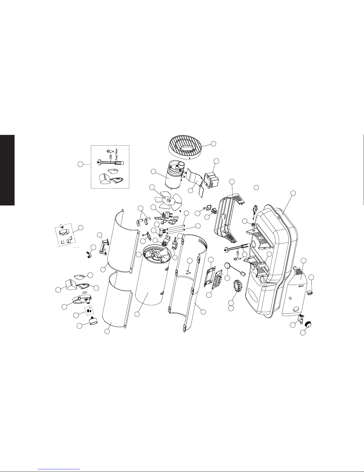
EXPLODED VIEW AND PARTS LIST 8
WIRING DIAGRAM 11
Model DXH50KTHC DXH75KTHC DXH135KTHC DXH175KTHC DXH210KTHC
Burn Rate: 50,000 BTU/hr (14.7 kW) 75,000 BTU/hr (22 kW) 125,000 BTU/hr (37 kW) 175,000 BTU/hr (51 kW) 210,000 BTU/hr (61.5 kW)
Fuel Rate: 0.37 gal/hr (1.5 L/hr) 0.55 gal/hr (2.1 L/hr) 0.96 gal/hr (3.5 L/hr) 1.3 gal/hr (5.0 L/hr) 1.6 gal/hr (6.0 L/hr)
Electrical Input
115 V, 60 HZ, 1 Ø, 3.5 A 1115 V, 60 HZ, 1 Ø, 4 A 115 V, 60 HZ, 1 Ø, 5.5 A 115 V, 60 HZ, 1 Ø, 5.5 A 115 V, 60 HZ, 1 Ø, 5.5 A
Min. operating voltage
110 V 110 V 110 V 110 V 110 V
Pressure Setting 3.5 psig (24 kPa) 4.2 psig (24 kPa) 5.1 psig (38 kPa) 6.8 psig (40 kPa) 8.2 psig (58.6 kPa)
Max. Outlet Temp. 1450 °F (787 °C) 1450 °F (787 °C) 1450 °F (787 °C) 1450 °F (787 °C) 1450 °F (787 °C)
Fuel Tank Capacity 4 gallons (15.1 L) 6 gallons (22.7 L) 8.45 gallons (32 L) 13.5 gallons (51 L) 13.5 gallons (51 L)
Ignition Direct Spark, Continuous Direct Spark, Continuous Direct Spark, Continuous Direct Spark, Continuous Direct Spark, Continuous
Spark Generator Igniter 13 kV, 10 ma Igniter 13 kV, 10 ma Igniter 13 kV, 10 ma Igniter 13 kV, 10 ma Igniter 13 kV, 10 ma
Primary Safety Control Solid State Control Solid State Control Solid State Control Solid State Control Solid State Control
Certification
Heater Specications
WARNING: If the information in this manual is not followed
exactly, a fire or explosion may result causing injury or loss of
life.
- Do not store or use gasoline or other flammable vapors and liquids in the
vicinity of this or any other appliance.
- Service must be performed by a qualified service agency.
DXH50KTHC & DXH75KTHC WARNING
Not suitable for use on wood floors or other combustible materials. When
used the heater should rest on a suitable insulating material at least 1 inch
thick and extending 3 feet or more beyond the heater in all directions.
CAUTION: CSA certied for use with only No. 1-K kerosene fuel.
Factory Tested: Kerosene, Diesel #1 and #2, Fuel Oil #1 and #2, JP8 (Jet A Fuel)
Page 4

English
4
Operating Precautions
This is a kerosene, direct-fired, forced air heater. It’s intended use is primarily
temporary heating of buildings under construction, alteration or repair.
Direct-Fired means that all of the combustion products enter the heated space. Even
though this heater operates very close to 100 percent combustion efficiency, it still
produces small amounts of carbon monoxide. Carbon monoxide (called CO) is toxic.
CO can build up in a heated space and failure to provide adequate ventilation could
result in death. The symptoms of inadequate ventilation are:
• headache
• dizziness
• burning eyes and nose
• nausea
• dry mouth or sore throat
Be sure to follow advice about ventilation in the Safety Precautions section.
Forced Air means that a blower or fan pushes the air through the heater. Proper
combustion depends upon this air flow; therefore, the heater must not be revised,
modified or operated with parts removed or missing. Likewise, safety systems must
not be circumvented or modified in order to operate the heater.
When the heater is to be operated in the presence of other people the user is
responsible for properly acquainting those present with the safety precautions and
instructions, and of the hazards involved.
Safety Precautions
THIS IS A HEATING APPLIANCE. DO NOT ATTEMPT TO WARM OR COOK
FOOD ON THIS HEATER.
1. Recommended for use with No.1-K kerosene fuel. Factory tested for use with No.2-K
kerosene, No.1 or No.2 Diesel, No.1 or No.2 fuel oil or JP8 Jet A fuel and these fuels may
be used as well. Never use gasoline, biodiesel, oil drained from crank cases, naphtha, paint
thinners, alcohol or any other highly flammable fuels.
2. Check the heater thoroughly for damage. DO NOT operate a damaged heater.
3. DO NOT modify the heater or operate a heater which has been modified from its
original condition.
4. Suitable for either outdoor or indoor use where adequate ventilation is provided. Never
use in areas normally for habitation. Not for use where exposed to weather.
5. Use in well ventilated areas, provide at least 2 sq. ft. (0.19 sq. m.) of opening near
the floor and 2 sq. ft. (0.19 sq. m.) near the ceiling directly to outdoors. Increase air
openings as marked for each additional heater.
6. Always keep combustibles, like paper and wood at least 8 ft. (2.4 m) from the
heater outlet and 3 ft. (1.0 m) from the top, sides and inlet. Locate 10 ft. (3.0 m)
from canvas or plastic coverings and secure them to prevent flapping movement.
7. Caution: Due to the high surface and exhaust temperatures, adults and children
must observe clearances to avoid burns or clothing ignition. Do Not Touch. Keep
children, clothing, and combustible away.
8. Install the heater such that it is not directly exposed to water spray, rain and / or
water.
9. Never use in areas normally for habitation and /or where children may be present.
10. Operate only on a stable, level surface.
(DXH50KTHC & DXH75KTHC – See wood floor warning on page 3).
11. Do not use with duct work. Do not restrict inlet or exit.
12. Use only with electrical power specified. The electrical connection and grounding
must comply with National Electrical Code – ANSI/NFPA 70 (USA) and CSA
C22.1 Canadian Electrical Code, Part 1 (Canada).
13. Use only a properly grounded 3-prong receptacle or extension cord.
14. Do not move, handle, or service while hot or in operation.
15. Use only in accordance with local, state (provincial) or national requirements,
ordinances and codes.
Operating Instructions
UNPACKING
1. Remove heater from carton.
2. Remove all protective material which may have been applied to the heater for shipment.
3. Check the heater for possible shipping damage. If any damage is found immediately
contact the manufacturer at 855-805-5745.
ASSEMBLY
(FOR 135,000, 175, AND 210 BTU/hr models only see page 10)
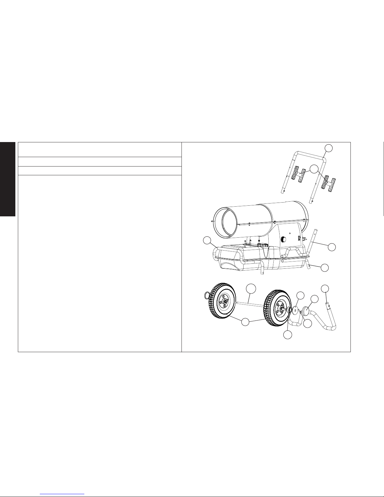
Wheels and handles are found in the shipping carton along with mounting hardware. The
wheels, axle and mounting hardware are in a package. Tools required are a 5/16” nut driver,
3/8” open or adjustable wrench and standard pliers.
1. Assemble the wheels onto the wheel support as shown.
2. Install one of the cotter pins into the hole on one end of axle.
3. Slide the large washer, then wheel onto the axle next to the cotter pin.
4. Slide the spacer onto the axle next to the wheel.
5. Slide the partially assembled axle through the wheel support frame.
6. Slide the spacer onto the axle next to the wheel support.
Page 5
5
English
7. Slide the wheel, then large washer onto the axle and hold in place with the remaining
cotter pin.
8. Install the caps over the larger washers to finish the wheel assembly.
PREPARATION FOR OPERATION
1. Check the heater for possible shipping damage. If any is found, immediately contact
the manufacturer at 855-805-5745.
2. Follow all of the “Precautions”.
3. Fill the fuel tank with clean kerosene. In extremely cold weather, condensation may
develop in the tank and it is recommended that a tablespoon of de-icer be added
for each gallon (4 liters) of fuel in the tank. When filling the heater, use at least 2
gallons (8 liters) of fuel. Be sure heater is level and do not overfill. Use a funnel or
can with a long fill spout.
IMPORTANT: Before lling fuel tank the rst time or after extended storage
periods, drain the fuel tank of any moisture or condensation.
4. Locate heater at a safe distance from combustible materials. Models DXH50K &
DXH75K are not suitable for use on wood floors or other combustible materials.
When used, the heater should rest on suitable insulating material at least 1 inch
thick and extending 3 ft. or more beyond the heater in all directions.
HEATER START UP
DXH50KTHC
1. Plug the heater into a grounded 115V, 60 Hz, 1 Ø outlet.
DXH75KTHC, DXH135KTHC, DXH175KTHC, DXH210KTHC
1. Turn thermostat to lowest setting and make sure “On/Off” switch is “Off”.
2. Plug the heater into a grounded 115V, 60 Hz, 1 Ø outlet.
3. Start heater by pushing toggle switch to “On” position (light signifies switch is in
“On” position.)
4. Adjust thermostat to desired setting. Heater will cycle on/off as heat is required.
NOTES FOR ALL MODELS:
• In cold weather (below 10 °F [-12.2 °C] ) starting may be improved by holding a nger over the vent hole of the pump adjustment screw cap until the
heater starts.
• This unit is equipped with an interrupt circuit. The reset is integrated into
the “On/Off” switch. If the unit does not start, toggle the switch to “Off”,
wait 5 min, and toggle the switch to “On”
• EXTENSION CORD REQUIREMENTS: Up to 100’ (30.5 M) use 16 awg conductor. 101’ - 200’ (30.5 - 61.0 m) use 14 awg conductor.
HEATER SHUT DOWN
DXH50KTHC
1. Unplug the heater from power source.
DXH75KTHC, DXH135KTHC, DXH175KTHC, DXH210KTHC
1. Push “On/Off” switch to “Off” position. For extended shutdown, unplug heater
from power source.
HEATER RESTART AFTER SAFETY SHUTDOWN
DXH50KTHC
1. Unplug the heater from power source.
2. Wait 5 minutes.
3. Plug the heater back into power source.
DXH75KTHC, DXH135KTHC, DXH175KTHC, DXH210KTHC
1. Toggle switch to “OFF” position
2. Wait 5 minutes
3. Restart
Maintenance and Storage
WARNING: To prevent personal injury, unplug the heater from the wall outlet
before servicing.
For maximum efficiency and trouble-free service, make the following periodic
maintenance, cleaning and inspections.
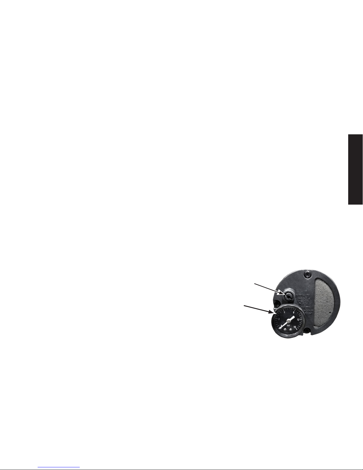
ADJUSTING PUMP PRESSURE
Due to varying fuel viscosities and normal component wear the pump pressure on
this heater may need to be adjusted.
FUEL PRESSURE ADJUSTMENT SCREW
(located at the rear of the heater)
PRESSURE GAGE
(not included on DXH50KTHC
or DXH75KTHC)
Page 6
English
6
ADJUSTMENT PROCEDURE
1. Fill fuel tank.
2. Start heater.
3. Locate the pressure adjustment screw, located on the back of the power pack assembly
and accessible by the handle of the heater.
4. Remove the rubber cap over the fuel pressure adjustment screw.
5. Using a flat bladed screw driver, turn the pump pressure adjustment screw:
• clockwise
to increase pump pressure
• counter-clockwise
to decrease pump pressure
By using the installed pressure gage (not included on DXH50KTHC) you may quantitatively
calibrate the pressure. The manufacturer’s recommended pump pressures are in the
specifications chart on page 3.
6. The desired qualitative burner characteristics are that the nose cone in the combustion
chamber should be cherry red with no dark spots and the flame should not extend
beyond the nose cone.
IMPROPER PRESSURE ADJUSTMENT
Problem: Heater does not have a strong consistent flame.
Heater smokes and spits raw fuel.
Nose cone does not get cherry red.
Adjustment: Pump pressure is too low.
Turn adjustment screw clockwise to increase pump pressure
Problem: Flame extends beyond the end of the heater.
Adjustment: Pump pressure is too high.
Turn adjustment screw counter clockwise to decrease pump pressure.
Daily Maintenance Schedule
1. GENERAL. Make general visual inspection of heater for loose or damaged parts.
Check nuts and bolts to insure against looseness caused by vibration or rough
handling. Damaged parts should be repaired or replaced before using heater
again. Check heater operation to be sure it is operating normally (See “Servicing”
section for description of normal operation).
2. FILTERS. Dirty air or fuel filters will cause an imbalance in the air-fuel mixture. The
best indication that this condition exists is an increase in odors or difficulty getting
your heater to ignite. This heater should never be operated without the filters
in place. If required, clean filters as described under “500 Hours” and “Annual
Schedules”.
500 Hour Maintenance Schedule
1. AIR INTAKE FILTER. Remove and wash the filter element with a mild detergent,
dry thoroughly and replace. Do not oil the filter element. If your heater is
used where there is considerable dust or dirt, clean as often as necessary
(approximately every 50 hrs.).
2. REMOVE DUST. Clean heater twice a season (more often under dusty conditions).
Remove accumulated dust from the transformer, burner, motor and fan blades
with compressed air. Wipe area clean with a clean dry cloth. Inspect area to insure
all foreign materials are removed, especially around the burner and combustion
area.
3. CAD CELL. Clean the glass portion of the cad cell with a soft dry cloth.
4. NOZZLE. Accumulation of dirt from fuel and carbon from the compressor vanes
will eventually fill up the passages in the nozzle, resulting in reduction of fuel and
air flow. Pressure will gradually increase giving improper fuel-air mixture and
excess odor and smoke. If this occurs, replace the fuel nozzle.
5. FUEL TANK. Clean twice a season (during frequently used periods, clean twice a
month). Drain and flush the fuel tank with clean fuel oil.
Annual Maintenance Schedule
1. AIR OUTPUT FILTER. Remove the air output filter and tap the contaminated side
gently on a solid object to remove contaminates. Compressed air or liquids should
not be used to clean this filter. Reinstall cleaned filter in filter body in the same
position as it was when removed. If the filter appears extremely dirty, replace it
with a new filter of the same type. When replacing the filter cover, be sure the
gasket is firmly in place and the screws in the filter cover are tight to prevent air
leaks.
2. FUEL FILTER. Remove the fuel filter from fuel line and direct compressed air
through the filter in the opposite direction of fuel flow. Safety glasses should be
worn when using compressed air.
3. AIR AND FUEL LINES. If the air or fuel lines are removed during cleaning, be sure
all connections are tight before operating unit.
Page 7

7
English
Storage
Store the heater in a dry location free from fumes or dust.
At the end of each heating season, clean the heater as described in the MAINTENANCE section. Drain and flush the fuel tank with clean fuel. The manufacturer
recommends completely filling the tank with fuel for extended storage to minimize
condensation inside the tank.
It is recommended to only store kerosene in containers that are marked
“KEROSENE”.
Servicing
A hazardous condition may result if a heater is used that has been modified or is not
functioning properly.
When the heater is working normally:
* The flame is contained within the heater.
* The flame is essentially yellow.
* There is no strong disagreeable odor, eye burning or other physical discomfort.
* There is not smoke or soot internal or external to the heater.
* There are no unplanned or unexplained shutdowns of the heater.
Troubleshooting
High limit switch open circuit
1. Make sure heater is cooled off, toggle switch to “OFF” position, wait 5 minutes and retry.
Sparks, calling for ame, but no or slow motor operation
1. Check wiring to motor (per wiring schematic in manual)
2. Make sure that the pressure gauge is in place and not damaged
3. Adjust pressure for proper heater operation per manual
4. With heater disconnected from AC source, rotate fan clockwise to verify motor is free
5. Remove air filter housing from motor and inspect the pump rotor for damage. If damaged,
replace rotor assembly.
6. If wiring is correct, pump rotor is okay, and motor is not rotating freely, replace motor or
power-pack assembly.
7. If problem persists, replace oil flame control assembly.
8. Check for spark arching from the electrode assembly, to the combustion cylinder.
9. Check the cad cell for continuity.
No Spark
1. Check length and gage of extension cord for proper amp. draw (check page 5)
2. Check wiring to igniter (per wiring schematic in manual)
3. Check gap between electrode probes (2.3 - 3mm)
4. Still no spark, replace igniter assembly
5. Replace oil flame control assembly
Abnormal Motor Operation - Motor overheats or Stops
1. Motor speed too low (Motor should operate at 3450 rpm) - Replace motor
2. With heater disconnected from AC source, rotate fan clockwise to verify motor is free
3. Remove air filter housing from motor and inspect the pump rotor for damage. If damaged,
replace rotor assembly
4. If wiring is correct, pump rotor is okay, and motor is not rotating freely, replace motor or
power-pack assembly
5. Replace oil flame control assembly
Unable to Detect Flame
1. Check wiring to cad cell (per wiring schematic in manual)
2. Clean cad cell photo cell
a) Slide cad cell out of cad cell holder
b) Push the photo cell out of the black rubber cad cell housing by pushing on the 2 purple
wires
c) Clean the photo cell with a soft cloth and rubbing alcohol
d) Pull the photo cell back into the cad cell housing and reinstall into holder
e) Test heater
3. If the heater still does not operate, replace cad cell
4. Replace oil flame control assembly
Flame Control Failure
1. Check wiring in heater (per wiring schematic in manual).
2. Replace oil flame control assembly.
Page 8
English
8
1
2
3
4
5
6
7
9
10
11
13
14
15
16
17
18
19
20
21
24
25
26
53
28
29
30
31
32
34
35
36
37
38
39
40
41
42
43
44
45
46
47
51
52
8
12
22
23
33
48
49
50
27
Filter Kit
51
52
Page 9
9
English
# 50K 75K 135K 175K 210K Description
1 21036 21036 21036 21036 21036 Power Cord
2 26958 26970 26974 27112 27112 Fuel Tank Assembly
3 **** 21883 21884 21885 21886 RadiationShield Ass’y
4 26960 26967 26975 26975 26975 Power Pac Ass’y
5 21686 24343 24346 24346 24346 Fuel Tube
6 21835 21836 21837 21837 21837 Grille Assembly
7 24011 24011 24011 24011 24011 Oil cad cell Bracket
8 28779 28779 28792 28793 28793 Fuel Filter
9 23449 23449 23449 23449 23449 Motor Cord Sleeve
10 26957 27144 26973 27111 27111 Bottom Shell
11 21844 27143 26972 27110 27110 Top Shell, Burner
12 21854 26966 26971 27109 27109 Top Shell, Insp. Cover
13 21864 21864 21865 21865 21865 Motor Mounting Brkt
14 **** 28788 28735 28735 28735 Start Capacitor
15 23725 23725 24345 24345 24345 Air Tube
16 26225 26225 26225 26225 26225 Snap Bushing
17 26962 21794 26901 22105 22105 High Limit Control
18 F226831 F226831 F226831 F226831 F226831 Kit, Rotor
19 **** 26898 26898 26898 26898 Receptacle, 110V
20 **** 22104 22104 22104 22104 AC Receptacle Cover
21 26833 26833 26833 26833 26833 Air Pump Cylinder
22 21810 21810 21810 21810 21810 Outlet Housing
23 21812 21812 21812 21812 21812 Inlet Housing
24 **** **** 22257 22257 22257 Burner Head Ass’y
25 F221887 F221887 F221887 F221887 F221887 Kit, Filter
26 21814 21814 21814 21814 21814 Outlet Filter
27 21815 21815 21815 21815 21815 Inlet Filter
28 F266842 F266842 F266842 F266842 F266842 Kit, Pump Adjustment
29 21866 21866 21867 21867 21867 Flame Control Ass’y
30 21816 21816 21816 21816 21816 Flame Control Bracket
31 F226865 F226865 F226865 F226865 F226865 cad cell Flame Sensor
32 21882 21868 21869 21870 21871
Comb.Chamber Cyl.
Ass’y
# 50K 75K 135K 175K 210K Description
33 26959 26959 26959 26959 26959 Fuel Cap
34 26910 26910 26910 26910 26910 Fuel Cap Gasket
35 27339 21817 21818 21818 21818 Motor
36 27790 27790 28739 28739 28739 Nozzle Adapter
37 27421 28740 26885 26866 26866 Fan
38 22142 22142 22142 22142 22142 Igniter Assembly
39
F227416 F221878 F221879 F221889 F221891
Fuel Air Aspir. Nozzle
40 26223 26223 26223 26223 26223 Strain Relief Bushing
41
F221857 F221857 F221857 F221857 F221857
Electrode Assembly
42 21820 21820 21820 21820 21820
Electrode Insulated
Cover
43 21821 21821 21821 21821 21821 Hose Barb Adapter
44 **** 21822 21822 21822 21822 Thermostat Knob
45 **** 21734 21734 21734 21734 Thermostat Assembly
46 28785 28785 28785 28785 28785 ON/OFF Switch
47 **** 28791 28778 22185 22185 Fuel Gauge
48 26964 21888 27107 27116 27116 Control Panel
49 26965 26968 27108 27117 27117 Control Panel Back
50 28786 28786 28786 28786 28786 Pressure Gauge, Round
51 40801 40801 **** **** **** Handle
52 21813 21813 21813 21813 21813 Gasket, Outlet Filter
* 24171 24171 **** **** **** Nozzle mtg. plate
* 26227 26227 26227 Snap Bushing
* 27429 27429 27429 27429 27429
Nozzle Ext. Retaining
Ring
* 28745 28745 **** **** **** Fuel Line Bushing
* **** 22146 22146 22146 22146 Bracket Thermostat Mtg.
* **** 26070 26070 26070 26070 Clamp Loop
REPLACEMENT PARTS LIST
* Not shown in Figure **** Not applicable to model
Page 10
English
10
* Not shown in drawing
Handle and wheel assembly for
DXH135KTHC, DXH175KTHC & DXH210KTHC only.
Ref. Item # Item # Item # Description
135K 175k 210K
1 40981 40981 40981 Wheel Assembly, 10”
2 27127 27129 27129 Upper Handle w/Spring Clips
* 27121 27121 27121 Lower Handle, Right
3 22173 22173 22173 Lower Handle, Left
* 27105 27105 27105 Leg Support, Right
4 27105 27105 27105 Leg Support, Left
5 27104 27132 27133 Support Leg
6 27128 27130 27131 Front Handle
7 28749 28749 28749 Large Retainer Washer
8 28750 28750 28750 Cotter Pin
9 28751 28751 28751 Hub Cap
10 28754 28754 28754 Extension Cord Caddy
11 21897 21897 21897 Wheel Spacer
12 22168 22184 22184 Axel
* 28787 28787 28787 Hardware Package
PARTS LIST
1
2
3
4
6
5
9
7
8
10
11
12
Page 11
11
English
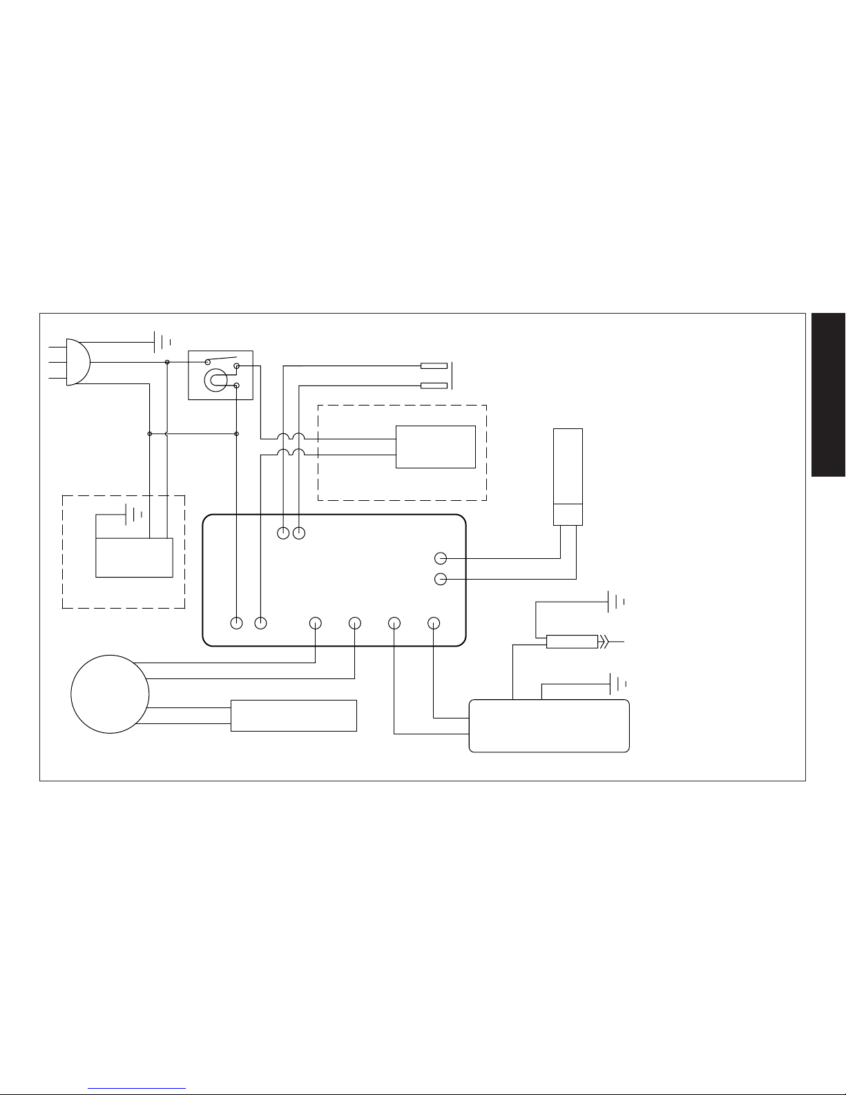
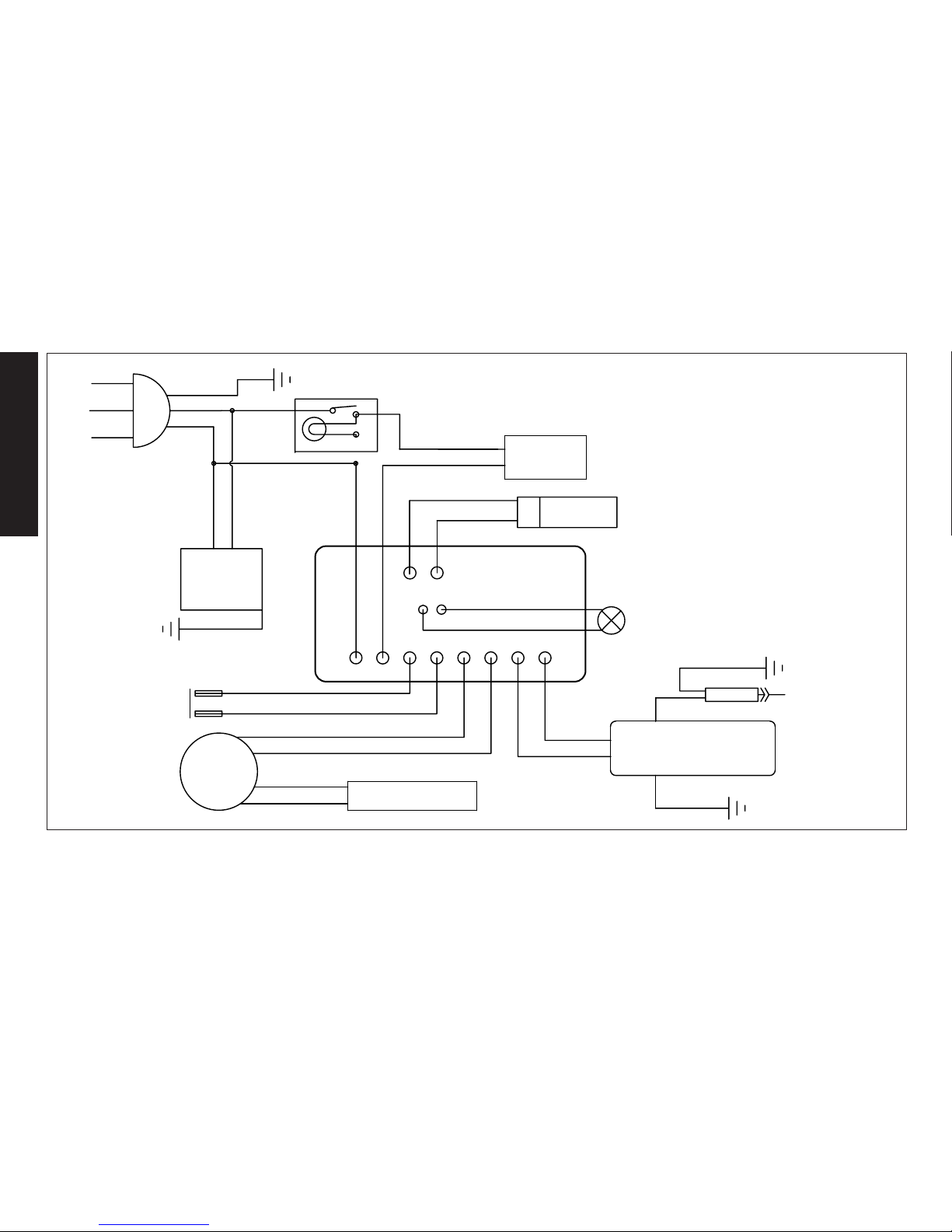
WIRING DIAGRAMS
DXH50KTHC
DXH75KTHC
18AWG BLUE
THERMOSTAT
18AWG PURPLE
COM1
I2
I1
M2
M1
L
N
18AWG PURPLE
18AWG GRN
18AWG BLK
18AWG WHT
18AWG YELL
18AWG YELL
FLAME CONTROL SCHEMATIC
(connections may not be in same
position on circuit board)
CORD SET
CAD CELL
HI-LIMIT
SWITCH
1
3
2
18AWG GRN
AC OUTLET
ON/OFF SWITCH
125KT,175KT,
210KT ONLY
75KT,125KT,175KT,210KT ONLY
18AWG PINK
18AWG PINK
MOTOR CAPACITOR
MOTOR
18AWG ORG
18AWG ORG
18AWG RED
18AWG RED
IGNITION TRANSFORMER
17AWG BLK
18AWG GRN
ELECTR0DE
17AWG BLK
18AWG BLK
18AWG WHT
H2
H1
The parts lists and wiring diagram show
the heater as it was constructed. Do not
use a heater which is different from that
shown. Heater performance is effected
by air pressure setting. If there is any
uncertainty about the air pressure setting,
have it checked. A heater which is not
working right must be repaired, but only by
a trained, experienced service person.
Page 12
English
12
WIRING DIAGRAMS
The parts lists and wiring diagram show the heater as it was constructed. Do not use a heater which is different from that shown. Heater performance is effected by air
pressure setting. If there is any uncertainty about the air pressure setting, have it checked. A heater which is not working right must be repaired, but only by a trained,
experienced service person.
ON/OFF SWITCH
AC OUTLET
18AWG GRN
18AWG ORG
18AWG ORG
2
3
1
IGNITION TRANSFORMER
MOTOR
HI-LIMIT
SWITCH
CORD SET
MOTOR CAPACITOR
CIRCUIT BOARD
18AWG YELL
18AWG YELL
18AWG RED
18AWG RED
18AWG WHT
18AWG BLK
18AWG GRN
18AWG PURPLE
18AWG PINK
18AWG PINK
1
2
3
4
5
6
18AWG PURPLE
THERMOSTAT
18AWG BLUE
7
8
ELECTR0DE
18AWG GRN
17AWG BLK
9
10
RED LED
11 12
18AWG BLUE
17AWG BLK
24AWG BLK
24AWG RED
18AWG BLK
18AWG WHT
CAD CELL
DXH135KTHC
DXH175KTHC
DXH210KTHC
Page 13

13
English
INSTRUCTION MANUAL
Kerosene Forced Air Heater
DXH50KTHC
DXH75KTHC
DXH135KTHC
DXH175KTHC
DXH210KTHC
DEWALT®, GUARANTEED TOUGH® and the
yellow and black color scheme are trademarks
of the DEWALT Industrial Tool Co., used under
license. ©2017 DEWALT. EGI/Enerco Group Inc.
Under license from Dewalt Industrial Tool Co
Warning
USE ONLY MANUFACTURER’S REPLACEMENT PARTS. USE OF ANY
OTHER PARTS COULD CAUSE INJURY OR DEATH. REPLACEMENT PARTS
ARE ONLY AVAILABLE DIRECT FROM THE FACTORY AND MUST BE
INSTALLED BY A QUALIFIED SERVICE AGENCY.
PARTS ORDERING INFORMATION:
PURCHASING: Accessories may be purchased at any Dewalt® local dealer or
direct from the factory
FOR INFORMATION REGARDING SERVICE:
Please call Toll-Free 855-805-5745
www.dewalt.com
Our office hours are 8:00 AM – 5:00 PM, EST, Monday through Friday.
Please include the model number, date of purchase, and description of
problem in all communication.
LIMITED WARRANTY
DeWalt® warrants its heaters and accessories to be free from defects in material and workmanship for a period of 2 years from date of purchase.
DeWalt® will repair or replace this product free of charge if it has been prove
to be defective within the 2 years period, and is returned at customer expense
with proof of purchase to DeWalt® within the warranty period.
UL733, CSA B140.8, CSA B140.9.3
Page 14

If you have questions or comments, contact us.
Pour toute question ou tout commentaire, nous contacter. Llámenos si tiene alguna pregunta o comentario.
855-805-5745 • www.dewalt.com
INSTRUCTION MANUAL
GUIDE DE’UTILISATION
MANUAL DE INSTRUCCIONES
SAVE THESE INSTRUCTIONS
CONSERVEZ CES INSTRUCTIONS
GUARDE ESTAS INSTRUCCIONES
DXH50KTHC, DXH75KTHC, DXH135KTHC, DXH175KTHC, DXH210KTHC
Kerosene Forced-aid Heater
Appareil de chauffage à air pulsé au Kérosène
Calentador Caldeo a aire forzado a Kerosene
READ INSTRUCTIONS CAREFULLY: Read
and follow all instructions. Place instructions
in a safe place for future reference. Do
not allow anyone who has not read these
instructions to assemble, adjust or operate
the heater.
VEUILLEZ LIRE ATTENTIVEMENT LES INSTRUCTIONS :
Lisez et observez toutes les instructions. Conservez
ces instructions dans un endroit sécuritaire pour vous
y référer ultérieurement. Interdisez à quiconque n’ayant
pas lu les présentes directives d’assembler, de régler
ou de faire fonctionner cette fournaise.
LEA CUIDADOSAMENTE LAS INSTRUCCIONES:
Lea y siga todas las instrucciones. Conserve
estas instrucciones en un lugar seguro para futura
referencia. No permita que nadie que no haya
leído estas instrucciones arme, ajuste o use el
calentador.
Page 15

Français
2
AVERTISSEMENT: NON CONÇU POUR ÊTRE UTILISÉ DANS UNE
HABITATION OU UN VÉHICULE RÉCRÉATIF.
AVERTISSEMENT G
ÉNÉRAL DE DANGER
:
LE NON-RESPECT DES MESURES DE PRÉVENTION ET INSTRUCTIONS
FOURNIES AVEC CET APPAREIL DE CHAUFFAGE RISQUE DE CAUSER LA MORT,
DES BLESSURES GRAVES ET DES DOMMAGES OU DES PERTES MATÉRIELLES
RÉSULTANT D’INCENDIE, D’EXPLOSION, DE BRÛLURE, D’ASPHYXIE,
D’INTOXICATION AU MONOXYDE DE CARBONE OU D’ÉLECTROCUTION.
SEULES LES PERSONNES APTES À COMPRENDRE ET À RESPECTER LES
INSTRUCTIONS DEVRAIENT UTILISER OU EFFECTUER L’ENTRETIEN DE CET
APPAREIL DE CHAUFFAGE.
SI VOUS AVEZ BESOIN D’AIDE OU D’INFORMATION AU SUJET DE L’APPAREIL
DE CHAUFFAGE (MANUEL D’INSTRUCTIONS, ÉTIQUETTES, ETC.), VEUILLEZ
COMMUNIQUER AVEC LE FABRICANT.
AVERTISSEMENT:
DANGER D’INCENDIE, D’EXPLOSION ET D’INHALATION.
CONSERVEZ LES MATÉRIAUX COMBUSTIBLES TELS QUE LES MATÉRIAUX DE
CONSTRUCTION, LE PAPIER ET LE CARTON À UNE DISTANCE SÉCURITAIRE DE
L’APPAREIL DE CHAUFFAGE COMME LE RECOMMANDENT LES INSTRUCTIONS.
N’UTILISEZ JAMAIS L’APPAREIL DE CHAUFFAGE DANS UN LOCAL QUI CONTIENT
OU RISQUE DE CONTENIR DES PARTICULES COMBUSTIBLES EN SUSPENSION
DANS L’AIR OU DES PRODUITS TELS QUE DE L’ESSENCE, DES SOLVANTS, DU
DILUANT À PEINTURE, DES PARTICULES DE POUSSIÈRE OU DES PRODUITS
CHIMIQUES INCONNUS.
AVERTISSEMENT: LE MONOXYDE DE CARBONE PEUT VOUSTUER
UTILISATION D’UN CHAUFFE PORTABLE DANS UN ESPACE CLOS PEUT PRODUIRE
AU MONOXYDE DE CARBONE MORTEL.
Cet appareil de chauffage portatif n’est pas ventilé. Il utilise l’oxygène de l’air
ambiant. Une circulation d’air adéquate doit être assurée pour la combustion et
la ventilation. Voir page3.
WARNINGS
AVERTISSEMENT:
• N’EMPLOYEZ PAS D’ESSENCE, DE NAPHTE OU DE PRODUITS
COMBUSTIBLES VOLATILS.
• ARRÊTEZ L’APPAREIL DE CHAUFFAGE AVANT D’Y AJOUTER DU
COMBUSTIBLE.
• REMPLISSEZ TOUJOURS LE RÉSERVOIR À L’EXTÉRIEUR, LOIN D’UNE
FLAMME NUE.
• N’UTILISEZ PAS DE SOURCE DE COMBUSTIBLE EXTERNE.
• NE FAITES PAS FONCTIONNER L’APPAREIL DE CHAUFFAGE SI DES VAPEURS
OU DES LIQUIDES INFLAMMABLES RISQUENT D’ÊTRE PRÉSENTS.
• NE DÉMARREZ PAS L’APPAREIL DE CHAUFFAGE SI LA CHAMBRE DE
COMBUSTION EST CHAUDE.
• NE DÉMARREZ PAS L’APPAREIL DE CHAUFFAGE SI UN SURPLUS DE
COMBUSTIBLE S’EST ACCUMULÉ DANS LA CHAMBRE DE COMBUSTION.
• NE PLACEZ PAS D’USTENSILES DE CUISSON SUR L’APPAREIL DE
CHAUFFAGE.
• BRANCHEZ LE CORDON ÉLECTRIQUE DANS UNE PRISE À TROIS BROCHES
ADÉQUATEMENT MISE À LA TERRE.
Dénitions : Directives de sécurité
Les dénitions ci-dessous décrivent le niveau de sévérité pour chaque mot signalétique. Veuillez lire le manuel et faire attention à ces symboles.
DANGER : Indique « une situation à risque imminent, laquelle, si elle n’est pas évitée, entraînera des blessures sérieuses ou la mort ».
AVERTISSEMENT :
Indique « une situation à risque potentiel, laquelle si elle n’est pas évitée, pourrait entraîner des blessures sérieuses ou la mort ».
MISE EN GARDE : Indique une situation dangereuse potentielle, laquelle, si elle n’est pas évitée, peut causer des blessures mineures ou des blessures légères.
AVIS : Indique une pratique non reliée à une blessure personnelle, laquelle, si elle n’est pas évitée, peut entraîner des dommages aux biens.
AVERTISSEMENT: LES SOUS-PRODUITS DE COMBUSTION ÉMIS LORS DE
L’UTILISATION DE CET APPAREIL CONTIENNENT DU MONOXYDE DE CARBONE, UN PRODUIT CHIMIQUE RECONNU PAR L’ÉTAT DE CALIFORNIE COMME
POUVANT CAUSER LE CANCER ET DES MALFORMATIONS CONGÉNITALES (OU
AUTRES DOMMAGES AU SYSTÈME REPRODUCTEUR). Pour plus d’informations,
visitez www.P65Warnings.ca.gov
Page 16

3
Français
TABLE DES MATIÈRES
AVERTISSEMENTS 2
SPÉCIFICATIONS DE CHAUFFAGE 3
PRÉCAUTIONS DE FONCTIONNEMENT ET DE SÉCURITÉ 4
INSTRUCTIONS D’ÉCLAIRAGE ET D’EXPLOITATION 5
ENTRETIEN 5
VUE ÉCLATÉE ET LISTE DES PIÈCES 8
SCHÉMA DE CÂBLAGE 11
Modèles
DXH50KTHC DXH75KTHC DXH135KTHC DXH175KTHC DXH210KTHC
Taux de combustion
: 50,000 BTU/hr (14,7 kW) 75,000 BTU/hr (22 kW) 125,000 BTU/hr (37 kW) 175,000 BTU/hr (51 kW) 210,000 BTU/hr (61,5 kW)
Consommation de combustible
: 0,37 gal/hr (1,5 L/hr) 0,55 gal/hr (2,1 L/hr) 0,96 gal/hr (3,5 L/hr) 1,3 gal/hr (5,0 L/hr) 1,6 gal/hr (6,0 L/hr)
Consommation électrique
115 V, 60 HZ, 1 Ø, 3,5 A 1115 V, 60 HZ, 1 Ø, 4 A 115 V, 60 HZ, 1 Ø, 5,5 A 115 V, 60 HZ, 1 Ø, 5,5 A 115 V, 60 HZ, 1 Ø, 5,5 A
Courant maximal 110 V 110 V 110 V 110 V 110 V
Pression 3,5 psig (24 kPa) 4,2 psig (24 kPa) 5,1 psig (38 kPa) 6,8 psig (40 kPa) 8,2 psig (58,6 kPa)
Température de sortie maximale:
1450 °F (787 °C) 1450 °F (787 °C) 1450 °F (787 °C) 1450 °F (787 °C) 1450 °F (787 °C)
Capacité du réservoir
4 gallons (15,1 L) 6 gallons (22,7 L) 8,45 gallons (32 L) 13,5 gallons (51 L) 13,5 gallons (51 L)
Allumage
Direct Spark, Continuous Direct Spark, Continuous Direct Spark, Continuous Direct Spark, Continuous Direct Spark, Continuous
Générateur d’étincelle
Igniter 13 kV, 10 ma Igniter 13 kV, 10 ma Igniter 13 kV, 10 ma Igniter 13 kV, 10 ma Igniter 13 kV, 10 ma
Appareil de commande
Solid State Control Solid State Control Solid State Control Solid State Control Solid State Control
Certification
Spécications
AVERTISSEMENT: Le non-respect des instructions, telles
u’indiquées dans le présent guide, risque d’entraîner une explosion
ou un incendie entraînant des dommages matériels ou des blessures
graves, voire mortelles.
- N’entreposez pas et n’utilisez pas d’essence ou d’autres liquides ou vapeurs
inflammables àproximité de ce type d’appareil.
- L’entretien doit être effectué par un fournisseur de services d’entretien qualifié.
AVERTISSEMENT RELATIF AUX MODÈLES DXH50KTHC ET DXH75KTHC
Non conçu pour être utilisé sur des planchers de bois ou d’autres matériaux
combustibles. Lors de son fonctionnement, l’appareil de chauffage doit reposer sur un matériau isolant adéquat d’au moins 2,5 cm (1 po) d’épaisseur et
dépassant l’appareil d’au moins 90 cm (3 pi) de tous les côtés.
PRUDENCE : CSA certié pour l’utilisation avec seulement No. 1-K le combustible de pétrole.
L’usine évaluée: No.2-K, No. 1 ou le gazole de No. 2, No. 1 ou le fuel de No. 2 ou le Jet de JP8
Page 17

Français
4
Précautions Liées au Fonctionnement
Cet appareil de chauffage à air pulsé et à feu direct fonctionne au kérosène. Il est
destiné principalement à chauffer temporairement des édifices en construction, en
rénovation ou en réparation.
Le fonctionnement à feu direct de cet appareil signifie que tous les produits de
combustion se retrouvent dans l’air ambiant. Même si la combustion de l’appareil de
chauffage est presque complète, il produit quand même de petites quantités de monoxyde de carbone. Le monoxyde de carbone (appelé CO) est toxique. Il est possible
que le CO s’accumule dans le local à chauffer. Une ventilation inadéquate pourrait
ainsi causer la mort. Les symptômes ressentis en cas de ventilation inadéquate sont
les suivants:
• mal de tête
• étourdissement
• sensation de brûlure au nez et aux yeux
• nausée
• mal de gorge ou bouche sèche
Assurez-vous de respecter les conseils au sujet de la ventilation mentionnés dans la
section Précautions liées à la sécurité.
Un appareil à air pulsé signifie que l’air est soufflé dans l’appareil de chauffage par une
soufflerie. La qualité de la combustion dépend du débit d’air. Par conséquent, l’appareil
de chauffage ne doit pas être modifié ni être utilisé si des pièces sont manquantes. De
même, les systèmes de sécurité ne doivent pas être contournés ni modifiés pour faire
fonctionner l’appareil.
Lorsque l’appareil de chauffage doit fonctionner en présence d’autres personnes,
l’utilisateur est responsable d’informer ces dernières des instructions et précautions liées
à la sécurité et de les avertir des dangers inhérents.
Précautions Liées au Fonctionnement À La Sécurité
CECI EST UN APPAREIL DE CHAUFFAGE. N’ESSAYEZ PAS DE CHAUFFER
OU DE CUIRE DES ALIMENTS SUR CE RADIATEUR.
1. Recommandé pour l’utilisation avec le combustible de pétrole No.1-K. L’usine évaluée pour
l’utilisation avec le pétrole No.2-K, No. 1 ou le gazole de No. 2, No. 1 ou le fuel de No. 2
ou le Jet de JP8. Un combustible et ces combustibles peuvent être utilisés aussi. N’utilisez
jamais de l’essence, le pétrole égoutté des cas de fanatique, le naphte, du diluant pour
peintures, de l’alcool ou autres combustibles extrêmement inflammables.
2. Vérifiez attentivement si l’appareil de chauffage a subi des dommages. NE FAITES PAS
fonctionner un appareil endommagé.
3. NE MODIFIEZ PAS l’appareil de chauffage et ne le faites pas fonctionner s’il n’est plus
dans son état d’origine.
4. Convient pour une utilisation en extérieur ou à l’intérieur lorsque la ventilation est
adéquate. Ne jamais utiliser dans des zones normalement habitables. Ne pas utiliser
lorsqu’il est exposé aux intempéries.L’appareil ne doit pas être exposé aux intempéries.
5. Faites fonctionner l’appareil dans des endroits bien aérés en laissant une ouverture
d’au moins 0,19m² (2pi²) près du plancher et une autre d’au moins 0,19m² (2pi²)
près du plafond, qui donnent directement sur l’extérieur. Augmentez la dimension de
ces ouvertures tel qu’indiqué pour chaque appareil de chauffage additionnel.
6. Gardez tous les matériaux combustibles, comme le papier et le bois, à au moins
2,4m (8pi) de la sortie de l’appareil de chauffage et à 1,0m (3pi) du dessus et des
côtés de l’appareil ainsi que de la prise d’air. Placez l’appareil à 3m (10pi) des toiles
et des revêtements plastiques, et fixez-les afin d’empêcher tout battement.
7. Attention : En raison des températures élevées à la surface et à la sortie, les adultes
et les enfants doivent respecter les distances de sécurité pour éviter les brûlures et
l’inflammation des vêtements. Ne touchez pas à l’appareil. Gardez les enfants, les
vêtements et les produits combustibles à bonne distance de l’appareil.
8. Placez l’appareil de chauffage de façon à ce qu’il ne soit pas exposé directement à
l’eau.
9. Ne l’utilisez jamais dans des endroits qui servent normalement à l’habitation ni où
sont présents des enfants.
10. Utilisez uniquement sur des surfaces stables et de niveau. (Modèles DXH50KTHC &
DXH75KTHC – Voir l’avertissement au sujet des planchers de bois.)
11. N’utilisez pas l’appareil avec des conduits d’air. N’obstruez pas l’entrée et la sortie
d’air.
12. Utilisez uniquement avec l’alimentation électrique spécifiée. Le raccordement
électrique et la mise à la terre doivent être conformes au Code national de
l’électricité – ANSI/NFPA 70 (É.-U.) – et au Code canadien de l’électricité – CSA
C22.1 – partie 1 (Canada).
13. N’utilisez qu’avec une fiche ou une rallonge mise à la terre munie de trois broches.
14. Ne déplacez pas l’appareil, ne lui touchez pas et n’essayez pas d’en faire l’entretien
lorsqu’il est chaud.
15. Utilisez-le uniquement en conformité avec les codes, les ordonnances et les
exigences de la province, de l’État ou de la municipalité concernés.
Intructions de Fonctionnement
Déballage
1. Retirez l’appareil de chauffage de la boîte.
2. Enlevez tout le matériel de protection installé sur l’appareil pour le transport.
3. Vérifiez soigneusement tout dommage qu’aurait pu subir l’appareil de chauffage pendant
l’expédition. Si vous constatez quelque dommage, avisez immédiatement le fabricant au
855-805-5745.
ASSEMBLAGE (Pour modèles de 135k, 175k, et 210k BTU/hr uniquement, voir page 10)
Les roues et les poignées se trouvent dans la boîte avec les pièces servant à l’assemblage.
Les roues, l’essieu et les pièces servant à l’assemblage se trouvent dans un emballage. Les
outils nécessaires sont une clé de 5/16 po, une clé ou une clé à molette de 3/8 po et une pince
ordinaire.
1. Assemblez les roues sur le cadre de support tel qu’illustré.
2. Insérez l’une des goupilles fendues dans le trou situé au bout de l’essieu.
3. Insérez la grande rondelle sur l’essieu, à côté de la goupille fendue, puis la roue.
4. Insérez un séparateur sur l’essieu jusqu’à côté de la roue.
Page 18

5
Français
5. Insérez l’essieu partiellement assemblé dans le cadre de support des roues.
6. Insérez un séparateur sur l’essieu jusqu’à côté du support de roue.
7. Insérez la roue sur l’essieu, puis la grande rondelle et fixez-les en place avec l’autre goupille
fendue.
8. Installez les capuchons sur les grandes rondelles pour terminer l’assemblage des roues.
AVANT LE FONCTIONNEMENT
1. Vérifiez soigneusement tout dommage qu’aurait pu subir l’appareil de chauffage
pendant l’expédition. Si vous constatez des dommages, avisez immédiatement le
fabricant au 855-805-5745.
2. Respectez toutes les «Précautions».
3. Remplissez le réservoir de kérosène propre. Dans des conditions de froid intense,
il est possible que de la condensation se forme dans le réservoir. Il est donc
recommandé d’ajouter une cuillère à table de liquide antigivrant par 4 litres (1
gallon) de combustible. Utilisez au moins 8litres (2gallons) de combustible lors du
remplissage du réservoir. Assurez-vous que l’appareil de chauffage est de niveau
et que le réservoir ne déborde pas. Servez-vous d’un entonnoir ou d’un contenant
muni d’un long bec verseur.
IMPORTANT : Avant de remplir le réservoir la première fois ou après des
périodes d’entreposage prolongées, enlevez-en la condensation.
4. Placez l’appareil de chauffage à une distance sécuritaire des matériaux
combustibles. Les modèles MH50KR et MH75KTR ne sont pas conçus pour être
utilisés sur des planchers de bois ni d’autres matériaux combustibles. Lors de
son fonctionnement, l’appareil de chauffage doit reposer sur un matériau isolant
adéquat d’au moins 2,5cm (1po) d’épaisseur et dépassant l’appareil d’au moins
90cm (3pi) ou plus de tous les côtés.
DÉMARRAGE DE L’APPAREIL
DXH50KTHC
1. Branchez le câble d’alimentation dans une prise mise à la terre de 115V, 60 Hz, 1Ø.
DXH75KTHC, DXH135KTHC, DXH180KTHC, DXH210KTHC
1. Réglez le thermostat au minimum et assurez-vous que l’interrupteur est à«OFF ».
2. Branchez le cordon de l’appareil de chauffage dans une prise mise à la terre de 115
V, 60 Hz, 1 Ø.
3. Démarrez l’appareil de chauffage en mettant l’interrupteur à « ON » (Marche) (La
lumière s’allume à la position « ON »)
4. Réglez le thermostat à la température désirée. L’appareil de chauffage s’arrêtera et
redémarrera au besoin.
Pour tous les modèles:
• Lorsque la température est inférieure à -12 °C (10 °F), le démarrage sera
facilité si l’on met un doigt sur l’orice de ventilation de la vis de réglage de
pression jusqu’à ce que l’appareil de chauffage démarre.
ARRÊT DE L’APPAREIL
DXH50KTHC
1. Débranchez l’appareil.
DXH75KTHC, DXH135KTHC, DXH175KTHC, DXH210KTHC
1. Placez l’interrupteur à« OFF ». Pour un arrêt prolongé, débranchez l’appareil de
chauffage de sa source d’alimentation.
HEATER RESTART AFTER SAFETY SHUTDOWN
DXH50KTHC
Débranchez l’appareil, attendez cinq minutes puis rebranchez l’appareil.
DXH75KTHC, DXH135KTHC, DXH175KTHC, DXH210KTHC
Placez l’interrupteur à«OFF», attendez 5minutes puis démarrez l’appareil.
Entretien et Entreposage
AVERTISSEMENT: Pour éviter toute blessure, débranchez l’appareil de
chauffage de la prise murale avant d’en effectuer l’entretien.
Pour optimiser le fonctionnement et éviter les problèmes, effectuez régulièrement les
inspections, le nettoyage et l’entretien suivants.
RÉGLAGE DE PRESSION DE LA POMPE
En raison des variations de viscosité des combustibles et de l’usure normale des
pièces, il peut devenir nécessaire de régler la pression de la pompe.
Réglage pression vis
(située à l’arrière de l’appareil de chauffage)
JAUGE DE PRESSION
(non inclus sur DXH50KTHC ou
DXH75KTHC)
• Cet appareil est équipé d’un disjoncteur intégré à l’interrupteur
marche-arrêt. Si l’appareil ne démarre pas, placez l’interrupteur à«OFF »,
attendez 5minutes et placez-le à « ON ».
• CONDITIONS POUR UTILISER UNE RALLONGE ÉLECTRIQUE: pour une
rallonge jusqu’à 30,5m (100pi), conducteurs de calibre16; pour une rallonge de 30,5 à 61m (101-200pi), conducteurs de calibre14.
Page 19

Français
6
POUR RÉGLER LA PRESSION
1. Remplissez le réservoir.
2. Démarrez l’appareil.
3. Repérez la vis du régulateur de pression de combustible. Cette vis est située à l’arrière,
sous le couvercle du boîtier de filtre à air (à environ 2 po à partir de la gauche et 1 po à partir
du haut).
4. Retirer et le capuchon en caoutchouc sur la vis de réglage de la pression du carburant.
5. À l’aide d’un tournevis plat, serrez la vis pour augmenter la pression ou desserrez-la
pour réduire la pression. Les pressions nominales sont indiquées dans le tableau des
spécifications à la page3 du Guide d’utilisation et instructions de fonctionnement.
• dans le sens horaire
augmente la pression de la pompe
• dans le sens antihoraire
diminue la pression de la pompe
6. Pour une efficacité maximale, le cône avant de la chambre de combustion doit être rouge
cerise sans présenter de taches foncées, et la flamme ne doit pas se prolonger au-delà du
cône.
SYMPTÔMES DE RÉGLAGE DE PRESSION INCORRECT
Problème: L’appareil ne produit pas une flamme forte et homogène.
L’appareil émet de la fumée et éjecte du combustible brut.
Le cône avant ne devient pas rouge cerise.
Ajustement La pression est trop faible.
Serrez la vis de réglage pour augmenter la pression de la pompe.
Problème: La flamme dépasse l’extrémité du tube de sortie.
Ajustement: La pression est trop forte.
Desserrez la vis pour réduire la pression de la pompe.
Programme Quotidien
1. GÉNÉRAL. Faites une inspection visuelle générale de l’appareil de chauffage
pour déceler les pièces endommagées ou desserrées. Inspectez les boulons et
les écrous pour vous assurer que les vibrations et les manipulations brusques
ne les ont pas desserrés. Les pièces endommagées doivent être réparées ou
remplacées avant d’utiliser à nouveau l’appareil de chauffage. Vérifiez si l’appareil
fonctionne normalement (consultez la section «Réparation» pour une description
du fonctionnement normal).
2. FILTRES. Les filtres à air et à combustible doivent être propres pour assurer
l’équilibre du mélange air-combustible. À défaut de quoi, l’odeur augmentera et
l’appareil de chauffage démarrera difficilement. Ne faites pas fonctionner l’appareil
sans les filtres. Si nécessaire, nettoyez les filtres tel qu’il est décrit aux sections
«Programme 500 heures» et «Programme annuel»
Programme 500 Heures
1. FILTRE D’ADMISSION D’AIR. Enlevez le filtre et lavez-le à l’aide d’un détergent
doux. Séchez-le à fond et remettez-le en place. Ne huilez pas l’élément filtrant. Si
vous utilisez l’appareil dans un endroit contenant beaucoup de poussières et de
saletés, nettoyez le filtre aussi souvent que requis (aux 50 heures environ).
2. ENLÈVEMENT DE LA POUSSIÈRE. Nettoyez l’appareil de chauffage deux fois
par saison (plus souvent dans les endroits poussiéreux). Enlevez la poussière
accumulée sur le transformateur, le brûleur, le moteur et les pales du ventilateur à
l’aide d’un jet d’air comprimé. Essuyez les surfaces avec un chiffon sec et propre.
Inspectez ces endroits pour vous assurer que toute matière étrangère a été
enlevée, particulièrement autour du brûleur et de la zone de combustion.
3. CELLULE AU CADMIUM. Nettoyez la partie vitrée de la cellule au cadmium à
l’aide d’un chiffon doux et sec.
4. GICLEUR. L’accumulation de saleté de combustible et de carbone causée par
l’aube d’entrée obstruera éventuellement les conduits du gicleur et entraînera
une diminution du débit d’air et de combustible. La pression augmentera
graduellement, ce qui déséquilibrera le mélange air-combustible et produira un
surplus de fumée et d’odeur. Dans un tel cas, remplacez le gicleur.
5. RÉSERVOIR DE COMBUSTIBLE. Nettoyez-le deux fois par saison (au cours des
périodes d’utilisation intensive, nettoyez-le deux fois par mois). Rincez et vidangez
le réservoir à l’aide de mazout propre.
Programme Annuel
1. FILTRE DE SORTIE D’AIR. Enlevez le filtre de sortie d’air et frappez-en doucement
le côté sale sur un objet dur pour enlever les saletés. N’utilisez pas d’air comprimé
ni de liquide pour nettoyer le filtre. Replacez le filtre propre dans son réceptacle
dans la position où il était. Si le filtre paraît extrêmement sale, remplacez-le par un
autre du même type. En remettant le couvercle du filtre en place, assurez-vous
que le joint d’étanchéité est solidement en place et que les vis du couvercle sont
assez serrées pour empêcher des fuites d’air.
2. FILTRE À COMBUSTIBLE. Enlevez le filtre de la canalisation de combustible
et dirigez de l’air comprimé à travers le filtre dans le sens contraire du débit
du combustible. Veuillez porter des lunettes protectrices en utilisant de l’air
comprimé.
3. CANALISATIONS D’AIR ET DE COMBUSTIBLE. Si ces canalisations sont
enlevées au cours du nettoyage, assurez-vous de bien serrer les raccords avant
de faire fonctionner l’appareil.
Page 20

7
Français
Entreposage
Entreposez l’appareil de chauffage dans un endroit sec exempt de vapeurs et de
poussières.
À la fin de chaque saison, nettoyez l’appareil de chauffage tel qu’indiqué dans la
section ENTRETIEN. Rincez et vidangez le réservoir à l’aide de combustible propre. Le
fabricant recommande de remplir complètement le réservoir de combustible avant un
entreposage prolongé pour diminuer les risques de condensation.
Il est recommandé de stocké le kérosène uniquement dans des conteneurs portant la
mention «KÉROSÈNE».
Entretien
Un appareil de chauffage qui a été modifié ou qui ne fonctionne pas correctement
risque d’être une cause de dangers.
Lorsque l’appareil de chauffage fonctionne normalement:
* La flamme reste dans l’appareil de chauffage.
* La flamme est vraiment jaune.
* Il n’y a pas de forte odeur désagréable, pas de sensation de brûlure aux yeux, ni de
malaise physique général.
* Il n’y a pas de fumée ni de suie à l’intérieur ou à l’extérieur de l’appareil de chauffage.
* Il ne se produit pas d’arrêts imprévus ou inexpliqués de l’appareil.
DIAGNOSTIC D’ARRÊT DE SÉCURITÉ ET DÉPANNAGE
Circuit ouvert d’interrupteur de limite élevée
1. Assurez-vous que la fournaise soit refroidie, basculez l’interrupteur à la position « OFF »,
attendez 5 minutes et essayez de nouveau.
Des étincelles se produisent cherchant une amme, mais il n’y a aucun
fonctionnement du moteur ou bien un fonctionnement lent de ce dernier
1. Vérifiez le câblage au moteur (selon le schéma de câblage dans le manuel).
2. Assurez-vous que le bouchon de la jauge de pression soit en place et non endommagé.
3. Réglez la pression pour un bon fonctionnement de la fournaise selon le manuel.
4. Avec la fournaise débranchée de la source CA, tournez le ventilateur dans le sens des
aiguilles d’une montre pour vérifier que le moteur soit libre.
5. Enlevez le bâti du filtre d’air du moteur et inspectez le rotor de la pompe pour tout dommage.
Si endommagé, remplacez l’assemblage du rotor.
6. Si le câblage est correct, que le rotor de la pompe est correct, et que le moteur ne tourne
pas librement, remplacez le moteur ou l’assemblage du bloc d’alimentation.
7. Si le problème persiste, remplacez l’assemblage du contrôle de la flamme d’huile.
8. Vérifiez pour toute étincelle arquant de l’assemblage de l’électrode au cylindre de
combustion.
9. Vérifiez la cellule au sulfure de cadmium pour la continuité.
Aucune étincelle
1. Vérifiez la longueur et la jauge de la rallonge électrique pour un ampérage correcte. (Voir les
exigences à la page 5.)
2. Vérifiez le câblage pour l’allumeur (selon le schéma de câblage dans le manuel).
3. Vérifiez l’espace entre les sondes d’électrodes (2,3 à 3,0 mm).
4. Toujours aucune étincelle, remplacez l’assemblage de l’allumeur.
5. Remplacez l’assemblage du contrôle de la flamme d’huile.
Fonctionnement anormal du moteur - Surchauffes ou arrêts du moteur
1. Vitesse du moteur trop basse (Moteur doit fonctionner à 3 450 RPM, sauf le 50K à 1 550
RPM) - Remplacez le moteur.
2. Avec la fournaise débranchée de la source CA, tournez le ventilateur dans le sens des
aiguilles d’une montre pour vérifier que le moteur soit libre.
3. Enlevez le bâti du filtre d’air du moteur et inspectez le rotor de la pompe pour tout
dommage. Si endommagé, remplacez l’assemblage du rotor.
4. Si le câblage est correct, que le rotor de la pompe est correct, et que le moteur ne tourne
pas librement, remplacez le moteur ou l’assemblage du bloc d’alimentation.
5. Remplacez l’assemblage du contrôle de la flamme d’huile.
Incapable de détecter la amme
1. Vérifiez le câblage à la cellule au sulfure de cadmium (selon le schéma de câblage dans le
manuel).
2. Nettoyez la cellule photovoltaïque de la cellule au sulfure de cadmium.
a) Glissez la cellule au sulfure de cadmium hors du support de la cellule au sulfure de
cadmium.
b) Poussez la cellule photovoltaïque hors du bâti en caoutchouc noir de la cellule au
sulfure de cadmium en poussant sur les 2 fils pourpres.
c) Nettoyez la cellule photovoltaïque avec un chiffon doux et de l’alcool à friction.
d) Remettez la cellule photovoltaïque dans le bâti de la cellule au sulfure de cadmium et
installez de nouveau dans le support.
e) Testez la fournaise.
3. Si la fournaise ne fonctionne pas, remplacez la cellule au sulfure de cadmium.
4. Remplacez l’assemblage du contrôle de la flamme d’huile.
Échec du contrôle de la amme
1. Vérifiez le câblage dans la fournaise (selon le schéma de câblage dans le manuel).
2. Remplacez l’assemblage du contrôle de la flamme d’huile.
Page 21

Français
8
1
2
3
4
5
6
7
9
10
11
13
14
15
16
17
18
19
20
21
24
25
26
53
28
29
30
31
32
34
35
36
37
38
39
40
41
42
43
44
45
46
47
51
52
8
12
22
23
33
48
49
50
27
Filter Kit
51
52
Page 22

9
Français
# 50K 75K 135K 175K 210K Description
1 21036 21036 21036 21036 21036 Cordon d’alimentation
2 26958 26970 26974 27112 27112 Réservoir de combustible
3 **** 21883 21884 21885 21886 Bouclier thermique
4 26960 26967 26975 26975 26975 Boîtier d’alimentation
5 21686 24343 24346 24346 24346
Canalisation du combustible
6 21835 21836 21837 21837 21837 Grille
7 24011 24011 24011 24011 24011
Support de cellule au cadmium
8 28779 28779 28792 28793 28793 Filtre à combustible
9 23449 23449 23449 23449 23449 Gaine du cordon moteur
10 26957 27144 26973 27111 27111 Coque inférieure
11 21844 27143 26972 27110 27110
Coque supérieure, brûleur
12 21854 26966 26971 27109 27109
Coque supérieure, inspection
13 21864 21864 21865 21865 21865 Support de moteur
14 **** 28788 28735 28735 28735
Condensateur de démarrage
15 23725 23725 24345 24345 24345 Canalisation d’air
16 26225 26225 26225 26225 26225 Bague pression
17 26962 21794 26901 22105 22105 Commande à maximum
18 F226831 F226831 F226831 F226831 F226831 Ensemble de rotor
19 **** 26898 26898 26898 26898 Réceptacle, 110V
20 **** 22104 22104 22104 22104 Couvercle de réceptacle
21 26833 26833 26833 26833 26833 Cylindre de pompe à air
22 21810 21810 21810 21810 21810 Boîtier de sortie
23 21812 21812 21812 21812 21812 Boîtier d’admission
24 **** **** 22257 22257 22257 Tête de brûleur
25 F221887 F221887 F221887 F221887 F221887 Ensemble de rotor
26 21814 21814 21814 21814 21814 Filtre de sortie
27 21815 21815 21815 21815 21815 Filtre d’entrée
28 F266842 F266842 F266842 F266842 F266842
Ensemble de réglage de pompe
29 21866 21866 21867 21867 21867 Commande de flamme
30 21816 21816 21816 21816 21816
Support de commande
de flamme
31 F226865 F226865 F226865 F226865 F226865 Capteur de flamme
32 21882 21868 21869 21870 21871
Cyl. chambre combustion
# 50K 75K 135K 175K 210K Description
33 26959 26959 26959 26959 26959 Bouchon de réservoir
34 26910 26910 26910 26910 26910 Joint de bouchon
35 27339 21817 21818 21818 21818 Moteur
36 27790 27790 28739 28739 28739 Adaptateur gicleur
37 27421 28740 26885 26866 26866 Ventilateur
38 22142 22142 22142 22142 22142 Allumeur
39
F227416 F221878 F221879 F221889 F221891
Embout entrée d’air
40 26223 26223 26223 26223 26223 Bague réd. tension
41
F221857 F221857 F221857 F221857 F221857
Électrode
42 21820 21820 21820 21820 21820 Couv. isolé d’électrode
43 21821 21821 21821 21821 21821 Adaptateur à barbelures
44 **** 21822 21822 21822 21822 Bouton thermostat
45 **** 21734 21734 21734 21734 Thermostat
46 28785 28785 28785 28785 28785 Interrupteur
47 **** 28791 28778 22185 22185 Jauge à combustible
48 26964 21888 27107 27116 27116 Panneau de commande
49 26965 26968 27108 27117 27117
Panneau de comm.,
arrière
50 28786 28786 28786 28786 28786 Manomètre
51 40801 40801 **** **** **** Poignée
52 21813 21813 21813 21813 21813 Joint de filtre de sortie
* 24171 24171 **** **** **** Plaque de gicleur
* 26227 26227 26227 Bague pression
* 27429 27429 27429 27429 27429 Bague de retenue ext.
* **** 22146 22146 22146 22146
Support de thermostat
de parenthèse
* **** 26070 26070 26070 26070 Boucle de serrage
* 28745 28745 **** **** **** Bague filtre combustible
REPLACEMENT PARTS LIST
* Non représenté sur la figure
**** Ne s’applique pas au modèle
Page 23

Français
10
* Not shown in drawing
Assemblage de la poignée et des roues – Modèles
DXH135KTHC, DXH175KTHC & DXH210KTHC
seulement.
Ref. Item # Item # Item # Description
135K 175k 210K
1 40981 40981 40981 Roues de 10 po
2 27127 27129 27129 Poignée supérieure
* 27121 27121 27121 Poignée inférieure, droite
3 22173 22173 22173 Poignée inférieure, gauche
* 27105 27105 27105 Support de patte, droit
4 27105 27105 27105 Support de patte, gauche
5 27104 27132 27133 Béquille
6 27128 27130 27131 Poignée avant avec essieu
7 28749 28749 28749 Grande rondelle
8 28750 28750 28750 Goupille fendue
9 28751 28751 28751 Chapeau de moyeu
10 28754 28754 28754 Support de rallonge électr.
11 21897 21897 21897 Séparateur
12 22168 22184 22184 Axe
* 28787 28787 28787 Ensemble de quincaillerie
PARTS LIST
1
2
3
4
6
5
9
7
8
10
11
12
Page 24

11
Français
SCHÉMA DE CÂBLAGE
DXH50KTHC
DXH75KTHC
La liste des pièces et le
schéma de câblage présentent
l’appareil de chauffage tel qu’il
a été construit. N’utilisez pas
un appareil de chauffage qui
diffère de ce qui est illustré.
Le rendement de l’appareil de
chauffage dépend du réglage de
la pression d’air. Si vous avez un
doute au sujet de la pression d’air,
faites-la vérifier.
Si l’appareil de chauffage ne
fonctionne pas correctement, il
doit être réparé uniquement par
un technicien qualifié.
COM1
I2
I1
M2
M1
L
N
1
3
2
H2
H1
VRT AWG 18
JAUNE AWG 18
INTERRUPTEUR COM
-
MANDE MAX.
JAUNE AWG 18
BLEU AWG 18
MODÈLES 75KT, 125KT, 175KT ET
210KT UNIQUEMENT
THERMOSTAT
VIOLET AWG 18
VIOLET AWG 18
NOIR AWG 17
VRT AWG 18
TRANSFORMATEUR D’AL
-
LUMAGE
NOIR AWG 17
ÉLECTRODE
RGE AWG 18
RGE AWG 18
CELLULE AU
CADMIUM
SCHÉMA DE LA COMMANDE
DE FLAMME
(la position des connexions peut
différer sur le circuit imprimé)
INTERRUPTEUR
MARCHE-ARRÊT
NOIR AWG 18
BLC AWG 18
VRT AWG 18
MODÈLES 125KT,175KT
ET 210KT UNIQUEMENT
PRISE C.A.
ORG AWG 18
CONDENSATEUR
DU MOTEUR
ORG AWG 18
ROSE AWG 18
ROSE AWG 18
MOTEUR
CORDON D’ALIMEN
-
TATION
Page 25

Français
12
La liste des pièces et le schéma de câblage présentent l’appareil de chauffage tel qu’il a été construit. N’utilisez pas un appareil de chauffage qui diffère de ce qui est
illustré. Le rendement de l’appareil de chauffage dépend du réglage de la pression d’air. Si vous avez un doute au sujet de la pression d’air, faites-la vérifier.
Si l’appareil de chauffage ne fonctionne pas correctement, il doit être réparé uniquement par un technicien qualifié.
DXH135KTHC
DXH175KTHC
DXH210KTHC
BLC AWG 18
NOIR AWG 18
2
3
1
1
2
3
4
5
6
7
8
9
10
11 12
VRT AWG 18
NOIR AWG 18
BLC AWG 18
CORDON D’ALI
-
MENTATION
INTERRUPTEUR
MARCHE-ARRÊT
JAUNE AWG 18
JAUNE AWG 18
THERMOSTAT
VIOLET AWG 18
VIOLET AWG 18
CELLULE AU
CADMIUM
VRT AWG 18
PRISE C.A.
ORG AWG 18
CONDENSATEUR
DU MOTEUR
ORG AWG 18
ROSE AWG 18
ROSE AWG 18
MOTEUR
RGE AWG 18
RGE AWG 18
TRANSFORMATEUR D’AL
-
LUMAGE
NOIR AWG 17
NOIR AWG 17
ÉLECTRODE
COMMUTATEUR
LIMITE HAUTE
JAUNE AWG 18
JAUNE AWG 18
VRT AWG 18
NOIR AWG 24
RGE AWG 24
CARTE DE CIRCUIT
IMPRIMÉ
LED ROUGE
SCHÉMA DE CÂBLAGE
Page 26

13
Français
GUIDE DE’UTILISATION
Appareil de chauffage à air pulsé au Kérosène
DXH50KTHC
DXH75KTHC
DXH135KTHC
DXH175KTHC
DXH210KTHC
Avertissement
UTILISER UNIQUEMENT LES PIÈCES DE RECHANGE D’ORIGINE
DU FABRICANT. L’UTILISATION D’AUTRES PIÈCES PEUT CAUSER
DES BLESSURES OU LA MORT. LES PIÈCES DE RECHANGE SONT
DISPONIBLES SEULEMENT DIRECTEMENT DU FABRICANT ET ELLES
DOIVENT ÊTRE INSTALLÉES PAR UNE AGENCE DE SERVICE QUALIFIÉE.
PARTS ORDERING INFORMATION:
PURCHASING: Accessories may be purchased at any Dewalt® local dealer or
direct from the factory
INFORMATION POUR LA COMMANDE DE PIÈCES:
APPROVISIONNEMENT : Il est possible d’acheter les accessoires auprès de
tout détaillant local DewaltMD ou alternativement, directement de l’usine
POUR DE L’INFORMATION CONCERNANT LE SERVICE:
Appeler sans frais au 855-805-5745
www.dewalt.com
Nos heures d’ouverture sont de 8h00 à 17h00, H.N.E, du lundi au vendredi.
Veuillez inclure votre numéro de modèle, la date d’achat, et une description
du problème dans toutes vos communications.
GARANTIE LIMITÉE
DeWalt® garantit que ses radiateurs et ses accessoires sont exempts de tout
défauts de matériaux et de fabrication pour une période de deux (2) ans à
compter de la date achat.
DeWalt® réparera ou remplacera ce produit sans les dépenses, si elles sont
jugées défectueuses au cours de cette période de deux (2) ans, et qu’il est retourné, aux frais du client, avec une copie de la preuve d’achat chez DeWalt®
pendant la période de garantie.
UL733, CSA B140.8, CSA B140.9.3
DEWALTMD, GUARANTEED TOUGHMD ainsi
que le schème jaune et noir sont des marques
déposées de DEWALT Industrial Tool Co., utilisés
sous licence. © DEWALT, 2017. EGI/Enerco Group
Inc. Sous licence de Dewalt Industrial Tool Co
Page 27

If you have questions or comments, contact us.
Pour toute question ou tout commentaire, nous contacter. Llámenos si tiene alguna pregunta o comentario.
855-805-5745 • www.dewalt.com
INSTRUCTION MANUAL
GUIDE DE’UTILISATION
MANUAL DE INSTRUCCIONES
SAVE THESE INSTRUCTIONS
CONSERVEZ CES INSTRUCTIONS
GUARDE ESTAS INSTRUCCIONES
DXH50KTHC, DXH75KTHC, DXH135KTHC, DXH175KTHC, DXH210KTHC
Kerosene Forced-aid Heater
Appareil de chauffage à air pulsé au Kérosène
Calentador Caldeo a aire forzado a Kerosene
READ INSTRUCTIONS CAREFULLY: Read
and follow all instructions. Place instructions
in a safe place for future reference. Do
not allow anyone who has not read these
instructions to assemble, adjust or operate
the heater.
VEUILLEZ LIRE ATTENTIVEMENT LES INSTRUCTIONS :
Lisez et observez toutes les instructions. Conservez
ces instructions dans un endroit sécuritaire pour vous
y référer ultérieurement. Interdisez à quiconque n’ayant
pas lu les présentes directives d’assembler, de régler
ou de faire fonctionner cette fournaise.
LEA CUIDADOSAMENTE LAS INSTRUCCIONES:
Lea y siga todas las instrucciones. Conserve
estas instrucciones en un lugar seguro para futura
referencia. No permita que nadie que no haya
leído estas instrucciones arme, ajuste o use el
calentador.
Page 28

Español
2
ADVERTENCIA: NO APTO PARA USAR EN EL HOGAR NI EN CASAS
RODANTES.
ADVERTENCIA GENERAL DE PELIGRO:
EL NO CUMPLIR CON LAS PRECAUCIONES E INSTRUCCIONES QUE VIENEN
CON ESTE CALENTADOR PUEDE CAUSAR LA MUERTE, LESIONES GRAVES Y
PÉRDIDAS Y DAÑOS MATERIALES DERIVADOS DEL PELIGRO DE INCENDIO,
EXPLOSIÓN, QUEMADURAS, ASFIXIA, ENVENENAMIENTO CON MONÓXIDO DE
CARBONO, Y/O DESCARGAS ELÉCTRICAS.
SOLO LAS PERSONAS QUE ENTIENDAN Y PUEDAN SEGUIR LAS
INSTRUCCIONES DEBEN USAR O MANTENER ESTE CALENTADOR.
SI NECESITA AYUDA O INFORMACIÓN ACERCA DEL CALENTADOR, COMO UN
MANUAL DE INSTRUCCIONES, ETIQUETAS, ETC., PÓNGASE EN CONTACTO
CON EL FABRICANTE.
ADVERTENCIA:
PELIGRO DE INCENDIO, QUEMADURAS, INHALACIÓN Y
EXPLOSIÓN. MANTENGA LOS COMBUSTIBLES SÓLIDOS, TALES COMO MATERIALES DE CONSTRUCCIÓN, PAPEL O CARTÓN, A UNA DISTANCIA SEGURA
DEL CALENTADOR. COMO SE RECOMIENDA EN LAS INSTRUCCIONES, NUNCA
USE EL CALENTADOR EN ESPACIOS QUE CONTENGAN O PODRÍAN CONTENER
COMBUSTIBLES VOLÁTILES O GASEOSOS, NI PRODUCTOS COMO GASOLINA,
SOLVENTES, DILUYENTES DE PINTURA, PARTÍCULAS DE POLVO O PRODUCTOS
QUÍMICOS DESCONOCIDOS.
ADVERTENCIA: EL MONÓXIDO DE CARBONO PUEDE CAUSARLE
LA MUERTE EL USO DE CALENTADORES PORTÁTILES EN UN LUGAR CERRA-
DO PUEDE PRODUCIR MORTAL MONÓXIDO DE CARBONO.
Este es un calentador portátil a gas sin fuente propia de ventilación. Utiliza
el aire (oxígeno) del área en la cual se emplea. Debe suministrarse el aire
necesario para la ventilación y la combustión. Ver página 3.
WARNINGS
ADVERTENCIA:
• NO UTILICE GASOLINA, NAFTA NI COMBUSTIBLES VOLÁTILES.
• APAGUE EL CALENTADOR ANTES DE AGREGAR COMBUSTIBLES.
• SIEMPRE LLÉNELO EN EL EXTERIOR LEJOS DE LLAMAS EXPUESTAS.
• NO UTILICE UNA FUENTE DE COMBUSTIBLE EXTERNA.
• NO UTILICE EL CALENTADOR DONDE HAYA LÍQUIDOS O VAPORES
INFLAMABLES.
• NO ENCIENDA EL CALENTADOR CUANDO LA CÁMARA ESTÉ CALIENTE.
• NO ENCIENDA EL CALENTADOR CUANDO SE HAYA ACUMULADO
COMBUSTIBLE EN EXCESO EN LA CÁMARA.
• NO COLOQUE UTENSILIOS DE COCINA SOBRE EL CALENTADOR.
• ENCHUFE EL CABLE ELÉCTRICO EN UN TOMACORRIENTE DE TRES
CLAVIJAS CORRECTAMENTE CONECTADO A TIERRA. EL USO DE
CALENTADORES PORTÁTILES EN UN LUGAR CERRADO PUEDE
PRODUCIR MORTAL MONÓXIDO DE CARBONO.
ADVERTENCIA: UNA DE LAS SUSTANCIAS QUE SE DESPRENDE EN LA
COMBUSTIÓN AL USAR ESTE EQUIPO ES EL MONÓXIDO DE CARBONO, UN
PRODUCTO QUÍMICO QUE DE ACUERDO CON EL ESTADO DE CALIFORNIA
PRODUCE CÁNCER Y DEFECTOS DE NACIMIENTO (U OTROS DAÑOS REPRODUCTIVOS). Para obtener más información, visite www.P65Warnings.ca.gov
Deniciones: Indicaciones de seguridad
Las siguientes definiciones describen el nivel de severidad para cada una de estas señales. Lea el manual y preste atención a estos símbolos.
PELIGRO: Indica una situación inminente de peligro, la que si no se evita, causará heridas graves o la muerte.
ADVERTENCIA: Indica una situación potencial de peligro, la que si no se evita, podría causar heridas graves o la muerte.
CUIDADO: Indica una situación potencial de peligro, la que si no se evita, podría resultar en heridas menores o moderadas.
AVISO: Indica una práctica no relacionada con heridas personales que, si no se evita, podría causar daños materiales.
Page 29

3
Español
CONTENTS
ADVERTENCIAS 2
ESPECIFICACIONES DEL CALENTADOR 3
PRECAUCIONES DE OPERACIÓN Y SEGURIDAD 4
ILUMINACIÓN Y INSTRUCCIONES DE OPERACIÓN 5
MANTENIMIENTO, ALMACENAMIENTO Y REPARACIÓN 5
LISTA DE PIEZAS 8
DIAGRAMA DE CABLEADO 11
Modelo DXH50KTHC DXH75KTHC DXH135KTHC DXH175KTHC DXH210KTHC
Tasa de combustión: 50,000 BTU/hr (14.7 kW) 75,000 BTU/hr (22 kW) 125,000 BTU/hr (37 kW) 175,000 BTU/hr (51 kW) 210,000 BTU/hr (61.5 kW)
Tasa de combustible: 0.37 gal/hr (1.5 L/hr) 0.55 gal/hr (2.1 L/hr) 0.96 gal/hr (3.5 L/hr) 1.3 gal/hr (5.0 L/hr) 1.6 gal/hr (6.0 L/hr)
Entrada de corriente:
115 V, 60 HZ, 1 Ø, 3.5 A 1115 V, 60 HZ, 1 Ø, 4 A 115 V, 60 HZ, 1 Ø, 5.5 A 115 V, 60 HZ, 1 Ø, 5.5 A 115 V, 60 HZ, 1 Ø, 5.5 A
Mín. Voltaje de operación:
110 V 110 V 110 V 110 V 110 V
Configuración de la presión:
3.5 psig (24 kPa) 4.2 psig (24 kPa) 5.1 psig (38 kPa) 6.8 psig (40 kPa) 8.2 psig (58.6 kPa)
Máx. Temperatura de salida:
1450 °F (787 °C) 1450 °F (787 °C) 1450 °F (787 °C) 1450 °F (787 °C) 1450 °F (787 °C)
Capacidad del tanque de
combustible:
4 gallons (15.1 L) 6 gallons (22.7 L) 8.45 gallons (32 L) 13.5 gallons (51 L) 13.5 gallons (51 L)
Ignición Direct Spark, Continuous Direct Spark, Continuous Direct Spark, Continuous Direct Spark, Continuous Direct Spark, Continuous
Generador de chispas: Igniter 13 kV, 10 ma Igniter 13 kV, 10 ma Igniter 13 kV, 10 ma Igniter 13 kV, 10 ma Igniter 13 kV, 10 ma
Control de seguridad
primario:
Solid State Control Solid State Control Solid State Control Solid State Control Solid State Control
Certificación
Especicaciones
ADVERTENCIA: si no se siguen al pie de la letra las instrucciones
de este manual, podría producirse un incendio o una explosión
que provocaría daños materiales, lesiones o muertes.
- No almacene ni utilice gasolina ni ningún otro vapor o líquido inflamable cerca
de este o de cualquier otro artefacto.
- El mantenimiento debe realizarlo una agencia de servicio calificada.
DXH50KTHC Y DXH75KTHC ADVERTENCIA
No es adecuado para usar sobre pisos de madera ni sobre otros materiales
combustibles. Cuando usa el calentador debe colocarlo sobre un material
aislante adecuado de al menos 1 pulgada de espesor y que sobresalga 3 pies
o más del calentador en todas las direcciones.
CUIDADO: certicación por CSA para uso únicamente con el combustible a base de kerosene n.° 1-K.
Probado en fábrica para utilizarlo con el kerosene N.º 2-K, diesel N.º 1 o N.º 2, fueloil N.º 1 o N.º 2 o combustible JP8 Jet A
Page 30

Español
4
Precauciones De Utilización
Este es un calentador de caldeo directo a aire forzado de kerosene. Está diseñado
principalmente para el calentamiento temporal de edificios en construcción, remodelación o reparación.
De caldeo directo quiere decir que todos los productos de la combustión ingresan al
espacio calentado. Aunque este calentador funciona casi a un 100% de eficiencia de
combustión, produce pequeáas cantidades de monóxido de carbono. El monóxido
de carbono (CO) es tóxico. El CO puede acumularse en el lugar que se calienta y si
no se establecen las condiciones de ventilación adecuadas puede resultar mortal. Los
síntomas de ventilación inadecuada son:
• dolor de cabeza
• mareos
• ardor en los ojos y en la nariz
• náuseas
• boca reseca o dolor de garganta
Asegúrese de seguir las recomendaciones sobre las condiciones de ventilación que se
incluyen en esta sección de precauciones de seguridad.
Aire forzado significa que un soplador o ventilador impulsa el aire a través del
calentador. La combustión depende de este flujo de aire para realizarse correctamente,
por tanto, el calentador no debe modificarse, alterarse o utilizarse si se le han sustraído
o le faltan partes. Asimismo, no se deben alterar ni modificar los sistemas de seguridad
para utilizar el calentador. Cuando deba utilizarse el calentador en presencia de otras
personas, el usuario será responsable de poner a los presentes al corriente de las
precauciones e instrucciones de seguridad, y de los posibles peligros.
Preauciones De Seguridad
ESTE ES UN APARATO DE CALEFACCIÓN. NO INTENTE CALENTAR O
COCINAR ALIMENTOS EN ESTE CALENTADOR.
1. Se recomienda utilizar con el combustible a base de kerosene N.º 1-K. Probado en
fábrica para utilizarlo con el kerosene N.º 2-K, diesel N.º 1 o N.º 2, fueloil N.º 1 o N.º 2 o
combustible JP8 Jet A, por lo que también es posible usar estos combustibles. Nunca
utilice gasolina, aceite drenado de los cárteres, nafta, diluyentes de pintura, alcohol o
cualquier otro combustible altamente inflamable.
2. Revise cuidadosamente si el calentador presenta daños. NO opere un calentador
dañado.
3. NO modifique el calentador ni opere un calentador cuya configuración original haya
sido modificada.
4. Adecuado para uso en exteriores o en interiores cuando la ventilación adecuada.
Nunca utilice normalmente en zonas habitables. No usar cuando se expone a la
intemperie.
5. Úselo en áreas bien ventiladas, deje al menos 2pies cuadrados (0.19metros
cuadrados) de abertura cerca del piso y 2pies cuadrados (0.19 metros cuadrados)
cerca del techo directamente hacia el exterior. Incremente las aberturas de aire tal como
se marcan para cada calentador adicional.
6. Siempre mantenga los materiales combustibles, como el papel y la madera, al
menos a 8pies (2.4m) de distancia de la salida del calentador y a 3pies (1.0m)
de distancia de la parte superior, los costados y la entrada. Colóquelo a 10pies
(3.0m) de las cubiertas de lona o plástico y asegúrelas de modo que no para que se
mantengan estáticas.
7. Cuidado: dadas las elevadas temperaturas de la superficie y del escape, tanto
los adultos como los niños deben mantener la distancia adecuada para evitar
quemaduras o la que prenda fuego la ropa. No tocar. Mantener alejados a los niños,
la ropa y el combustible.
8. Instale el calentador de forma tal que no esté directamente expuesto a salpicaduras
de agua, lluvia y/o agua.
9. Nunca lo use en áreas generalmente habitadas y/o en donde se encuentren niños.
10. Úselo únicamente sobre una superficie nivelada y estable. (DXH50KTHC &
DXH75KTHC – Ver la precaución sobre los pisos de madera página 3
11. No utilizar en redes de conductos. No restringir las entradas ni las salidas.
12. Utilice únicamente la alimentación de corriente especificada. La conexión eléctrica
y a tierra debe cumplir con los requisitos del Código Eléctrico Nacional - ANSI/
NFPA 70 (EE.UU.) y del Código Eléctrico Canadiense CSA C22.1, Primera parte
(Canadá).
13. Utilice únicamente un cable de extensión o un receptáculo de 3 clavijas
correctamente conectado a tierra.
14. No mueva, manipule ni ajuste el calentador mientras esté caliente o encendido.
15. Utilícelo conforme con los requisitos, las ordenanzas y los códigos locales, estatales
(provinciales) o nacionales.
Instrucciones De Operación
DESEMPACADO
1. Saque el calentador de la caja.
2. Quite todo el material de protección aplicado al calentador para su envío.
3. Revise si el calentador para determinar si sufrió daáos durante el envío. Si encuentra algún
daño, comuníquese inmediatamente con el fabricante al 855-805-5745.
ONTAJE (para los modelos 135,000, 175, AND 210 BTU/hr únicamente ver página10).
Las ruedas y los mangos en la caja de envío vienen junto a los accesorios de montaje. Las
ruedas, el eje y los accesorios de montaje se encuentran en un paquete. Las herramientas
necesarias son una llave para tuercas de 5/16”, una llave inglesa abierta o ajustable de 3/8” y
pinzas estándar.
1. Ensamble las ruedas en el soporte para ruedas tal como se muestra.
2. Instale una de las chavetas en el orificio en uno de los extremos del eje.
3. Deslice la arandela grande, luego la rueda para que encajen en el eje junto a la chaveta.
4. Deslice el espaciador en el eje junto a la rueda.
Page 31

5
Español
5. Deslice el eje parcialmente ensamblado a través del bastidor de soporte de la rueda.
6. Deslice el espaciador en el eje junto al soporte de la rueda.
7. Deslice la rueda y luego la arandela grande por el eje y manténgalo en su lugar con la
chaveta restante.
8. Instale las tapas sobre las arandelas grandes para terminar con el ensamblaje de la rueda.
PREPARATIVOS PARA OPERACIÓN
1. Revise si el calentador para determinar si sufrió daños durante el envío. Si encuentra
alguno, comuníquese inmediatamente con el fabricante al 855-805-5745.
2. Siga todas las “Precauciones”.
3. Llene el tanque de combustible con kerosene limpio. En condiciones climáticas
extremadamente frías, se puede desarrollar la condensación en el tanque, por lo que
se recomienda agregar una cucharada de anticongelante por cada galón (4 litros)
de combustible en el tanque. Cuando llene el calentador, use al menos 2 galones (8
litros) de combustible. Asegúrese de que el calentador esté nivelado y no lo llene de
más. Utilice un embudo o una lata con un pico de llenado largo.
IMPORTANTE: antes de llenar el tanque de combustible la primera vez o
después de períodos de almacenamiento extendidos, drene el tanque de
combustible para retirar la humedad y la condensación.
4. Coloque el calentador a una distancia segura de los materiales combustibles. Los
modelos MH50KR y MH75KTR no son adecuados para usarse en pisos de madera
u otros materiales combustibles. Cuando lo use debe colocar el calentador sobre
un material aislante adecuado de al menos 1pulgada de espesor y que sobresalga
3pies o más del calentador en todas las direcciones.
ENCENDIDO DEL CALENTADOR
DXH50KTHC
1. enchufe el calentador en un tomacorriente con clavija de tierra de 115 V, 60 Hz, 1 Ø.
DXH75KTHC, DXH135KTHC, DXH175KTHC, DXH210KTHC
1. gire el termostato al ajuste más bajo, asegurándose de que el interruptor “On/Off”
quede en la posición “Off”.
2. Enchufe el calentador en un tomacorriente con clavija de tierra de 115 V, 60 Hz, 1 Ø.
3. Gire el termostato al ajuste más alto. Para encender el calentador, coloque el
interruptor en la posición “On” (la luz significa que el interruptor se encuentra en la
posición “ON”).
4. Ajuste el termostato en el valor deseado. El calentador se prende y apaga según se
necesite o no calor.
PARA TODOS LOS MODELOS:
• En condiciones climáticas frías, (menos de -12 C° [10F°]), puede mejorarse
el encendido si se pone el dedo sobre el oricio de ventilación de la tapa del
tornillo de ajuste de la bomba hasta que el calentador se encienda.
• Esta unidad viene equipada con un circuito de interrupción. El reinicio está
integrado al interruptor “On/Off”. Si la unidad no se enciende, cambie el
interruptor a la posición “Off”, espere 5minutos y cambie el interruptor a la
posición “On”.
• REQUISITOS DEL CABLE DE EXTENSIÓN: hasta 100’ (30.5m) use un
conductor de calibre 16 awg. 101’ - 200’ (30.5 - 61.0m) use un conductor
de calibre 14 awg.
APAGADO DEL CALENTADOR
DXH50KTHC desenchufe el calentador de la alimentación.
DXH75KTHC, DXH135KTHC, DXH175KTHC, DXH210KTHC
ponga el interruptor “On/Off” en la posición “Off”. Para un apagado prolongado,
desconecte el calentador de la alimentación.
REINICIO LUEGO DEL APAGADO DE SEGURIDAD
DXH50KTHC
1. desenchufe la unidad. 2. Espere 5 minutos. 3. Enchúfela nuevamente
DXH75KTHC, DXH135KTHC, DXH175KTHC, DXH210KTHC
1. cambie el interruptor a la posición “OFF” 2. espere 5 minutos 3. Reinicie
Mantenimiento Y Almacenamiento
ADVERTENCIA: Para evitar lesiones personales, desenchufe el calentador
de la salida de corriente de la pared antes de realizar la reparación.
Para una mayor eficacia y reparación sin problemas, realice las siguientes
actividades periódicas de mantenimiento, limpieza e inspección.
AJUSTE DE LA PRESIÓN DE LA BOMBA
Debido a las viscosidades variables de combustible y el desgaste normal de los
componentes, puede que deba ajustarse la presión de la bomba de este calentador.
Ajuste de la presión del tornillo
(situado en la parte trasera del calentador)
GAGE DE PRESIÓN
(no incluido en DXH50KTHC o
DXH75KTHC)
Page 32

Español
6
PROCEDIMIENTO DE AJUSTE:
1. Llene el tanque de combustible.
2. Encienda el calentador.
3. Ubique el tornillo de ajuste de presión de combustible. El tornillo de ajuste de presión se
encuentra en la parte posterior del calentador, en la tapa de la cubierta del filtro de aire
(aprox. a 2” del lado izquierdo y a 1” de la parte superior).
4. Quite y deseche la tapa de goma para dejar expuesto el tornillo.
5. Con un destornillador de punta plana, gire el tornillo de ajuste de presión de la bomba
en sentido horario para aumentar la presión de la bomba y/o en sentido antihorario para
disminuir la presión de la bomba. Las presiones base de la bomba pueden encontrarse
en el cuadro de especificaciones en la página 3 de las “Instrucciones de uso y manual del
usuario”.
• en sentido horario
para aumentar la presión de la bomba
• en sentido antihorario para disminuir la presión de la bomba
6. Para obtener mejores resultados, el husillo de la cámara de combustión debe ser de color
rojo cereza sin puntos oscuros y la llama no debe sobrepasar al husillo.
AJUSTE DE PRESIÓN INADECUADO
Problema: el calentador no mantiene una llama fuerte constante.
El calentador humea y despide combustible crudo.
El husillo no toma color rojo cereza.
Ajuste: la presión de la bomba es demasiado baja.
Gire el tornillo de ajuste en sentido horario para aumentar la presión
de la bomba.
Problema: la llama se extiende más allá del extremo del calentador.
Ajuste: la presión de la bomba es demasiado alta.
Gire el tornillo de ajuste en sentido antihorario para disminuir la
presión de la bomba.
Cronograma Diario
1. GENERAL. Realice una inspección visual general del calentador para detectar
piezas sueltas o dañadas. Verifique las tuercas y los pernos para asegurarse
de que no estén sueltos debido a la vibración o al mal uso. Las piezas dañadas
deben repararse o reemplazarse antes de utilizar el calentador nuevamente.
Verifique el funcionamiento del calentador para asegurarse de que funcione
normalmente (Consulte la sección de “Reparación” para obtener una descripción
del funcionamiento normal).
2. FILTROS. El aire o los filtros sucios provocarán un desequilibrio en la mezcla airecombustible. La mejor indicación de que este problema existe es un aumento en
los olores o la dificultad para encender su calentador. No se debe hacer funcionar
el calentador sin los filtros en su lugar. Si es necesario, los filtros limpios se
describen en “500 horas” y “Cronogramas anuales”.
Cronograma De 500 Horas
1. FILTRO DE ADMISIÓN DE AIRE. Quite y lave el elemento del filtro con un detergente
suave, séquelo por completo y reemplácelo. No aceite el elemento de filtro. Si su
calentador se utiliza en lugares considerablemente sucios o con polvo, límpielo
cuantas veces sea necesario (aproximadamente cada 50horas).
2. QUITE EL POLVO. Limpie el calentador dos veces por temporada (con más
frecuencia cuando hay polvo). Quite el polvo acumulado del transformador,
quemador, motor y aspas del ventilador con aire comprimido. Limpie el área con un
paño seco y limpio. Inspeccione el área para asegurarse de quitar todos los materias
extrañas, especialmente alrededor del quemador y del área de combustión.
3. CÉLULA DEL CAD. Limpie la parte de vidrio de la célula del cad con un paño suave y
seco.
4. PICO. La acumulación de suciedad del combustible y del carbón de las aspas del
compresor eventualmente llena los pasajes del pico, lo que provoca una reducción
del flujo de combustible y aire. La presión aumenta gradualmente y provoca una
mezcla inadecuada de combustible y aire, y olor y humo en exceso. Si esto sucede,
cambie el pico de combustible.5. FUEL TANK. Clean twice a season (during
frequently used periods, clean twice a month). Drain and flush the fuel tank with clean
fuel oil.
5. TANQUE DE COMBUSTIBLE. Límpielo dos veces por temporada (durante períodos
de uso frecuente, límpielo dos veces por mes). Drene y enjuague el tanque de
combustible con fueloil limpio.
Cronograma Anual
1. FILTRO DE SALIDA DE AIRE. Quite el filtro de salida de aire y golpee suavemente
el lado contaminado contra un objeto sólido para quitar los contaminantes. El
aire comprimido o los líquidos no deben utilizarse para limpiar este filtro. Instale
nuevamente el filtro limpio en el cuerpo del filtro en la misma posición en la que
estaba cuando se quitó. Si parece que el filtro está demasiado sucio, cámbielo por
un nuevo filtro del mismo tipo. Cuando cambie la tapa del filtro, asegúrese de que la
junta esté sujeta firmemente en su lugar y que los tornillos de la tapa del filtro estén
ajustados para evitar fugas de aire.
2. FILTRO DE COMBUSTIBLE. Quite el filtro de combustible de la línea de combustible
y haga pasar el aire comprimido a través del filtro en sentido opuesto al flujo del
combustible. Se deben usar gafas de protección cuando se usa aire comprimido.
3. LÍNEAS DE AIRE Y COMBUSTIBLE. Si se quitan las líneas de aire o combustible
durante la limpieza, asegúrese de que todas las conexiones estén ajustadas antes de
volver a usar la unidad.
Page 33

7
Español
Almacenamiento
Guarde el calentador en un lugar seco sin vapores ni polvo.Al término de cada
temporada de calefacción, limpie el calentador como se describe en la sección de
MANTENIMIENTO. Drene y enjuague el tanque de combustible con combustible limpio.
El fabricante recomienda llenar el tanque con combustible por completo en caso de
almacenamiento prolongado para minimizar la condensación dentro del tanque.
Se recomienda almacenar únicamente queroseno en contenedores marcados con
“KEROSENE”.
Reparación
Se puede producir una situación de riesgo si se utiliza un calentador cuya configuración
original haya sido modificada o si no está funcionando correctamente.
Cuando el calentador funciona normalmente:
* La llama arde al interior del calentador.
* La llama es esencialmente amarilla.
* No se percibe un olor desagradable fuerte, no arden los ojos y no hay ningún otro
tipo de incomodidad física.
* No hay humo ni hollín dentro ni fuera del calentador.
* El calentador no se apaga inesperadamente o inexplicablemente.
Troubleshooting
Interruptor limitador máximo en circuito abierto
1. Asegúrese de que el calentador se enfríe por completo, cambie el interruptor a la posición
“OFF”, espere 5minutos e inténtelo nuevamente.
Chispas piden llama, pero el motor no funciona o funciona lentamente
1. Verifique el cableado al motor (según el esquema de cableado del manual).
2. Asegúrese de que el indicador de presión esté en su lugar y no esté dañado.
3. Ajuste la presión para un funcionamiento adecuado del calentador según el manual.
4. Con el calentador desconectado de la alimentación de CA, gire el ventilador en sentido
horario para verificar que el motor esté libre.
5. Quite la cubierta del filtro de aire del motor e inspeccione el rotor de la bomba para verificar si
hay daños. Si está dañado, reemplace el conjunto del rotor.
6. Si el cableado es correcto y el rotor de la bomba está en buenas condiciones, pero el motor
no gira libremente, reemplace el motor o el conjunto de la unidad de alimentación.
7. Si el problema persiste, reemplace el conjunto de control de la llama de aceite.
8. Verifique el arco de la chispa del conjunto de electrodo al cilindro de combustión.
9. Verifique la célula del cad para comprobar la continuidad.
Sin chispa
1. Verifique la longitud y el calibre del cable de extensión para comprobar que la corriente
arrastrada sea la adecuada. (Verifique los requisitos en la página 45.
2. Verifique el cableado al encendedor (según el esquema de cableado del manual).
3. Verifique el espacio entre las sondas de electrodos (2.3 - 3mm).
4. Aún sin chispa, reemplace el conjunto del encendedor.
5. Reemplace el conjunto de control de la llama de aceite.
Funcionamiento anormal del motor - El motor se recalienta o se detiene
1. Velocidad del motor demasiado baja (el motor debe funcionar a 3450rpm) - Reemplace
el motor.
2. Con el calentador desconectado de la alimentación de CA, gire el ventilador en sentido
horario para verificar que el motor esté libre.
3. Quite la cubierta del filtro de aire del motor e inspeccione el rotor de la bomba para
verificar si hay daños. Si está dañado, reemplace el conjunto del rotor.
4. Si el cableado es correcto y el rotor de la bomba está en buenas condiciones, pero el
motor no gira libremente, reemplace el motor o el conjunto de la unidad de alimentación.
5. Reemplace el conjunto de control de la llama de aceite.
No se puede detectar la llama
1. Verifique el cableado a la célula del cad (según el esquema de cableado del manual).
2. Célula del cad limpia, fotocélula.
a) Deslice la célula del cad para retirarla del sujetador del cad.
b) Empuje la fotocélula hacia afuera de la cubierta de goma negra de la célula del cad
presionando sobre los 2 cables púrpura.
c) Limpie la fotocélula con un paño suave y alcohol.
d) Tire la fotocélula nuevamente hacia la cubierta de la célula del cad y vuelva a instalarla
en el soporte.
e) Pruebe el calentador.
3. Si el calentador aún no funciona, reemplace la célula del cad.
4. Reemplace el conjunto de control de la llama de aceite.
Falla del control de la llama
1. Verifique el cableado en el calentador (según el esquema de cableado del manual).
2. Reemplace el conjunto de control de la llama de aceite.
Page 34

Español
8
1
2
3
4
5
6
7
9
10
11
13
14
15
16
17
18
19
20
21
24
25
26
53
28
29
30
31
32
34
35
36
37
38
39
40
41
42
43
44
45
46
47
51
52
8
12
22
23
33
48
49
50
27
Filter Kit
51
52
Page 35

9
Español
# 50K 75K 135K 175K 210K Description
1 21036 21036 21036 21036 21036 Cable de alimentación
2 26958 26970 26974 27112 27112
Conjunto del tanque de combus-
tible
3 **** 21883 21884 21885 21886
Conjunto de protección contra la
radiación
4 26960 26967 26975 26975 26975
Conjunto de la unidad de ali-
mentación
5 21686 24343 24346 24346 24346 Tubo de combustible
6 21835 21836 21837 21837 21837 Conjunto de la rejilla
7 24011 24011 24011 24011 24011
Soporte de la célula del cad de
aceite
8 28779 28779 28792 28793 28793 Filtro de combustible
9 23449 23449 23449 23449 23449 Cubierta del cable del motor
10 26957 27144 26973 27111 27111 Carcasa inferior
11 21844 27143 26972 27110 27110 Carcasa superior, quemador
12 21854 26966 26971 27109 27109 Carcasa superior, insp. Tapa
13 21864 21864 21865 21865 21865 Soporte de montaje del motor
14 **** 28788 28735 28735 28735 Condensador de arranque
15 23725 23725 24345 24345 24345 Tubo de aire
16 26225 26225 26225 26225 26225 Cojinete de cierre
17 26962 21794 26901 22105 22105 Control de limitador máximo
18 F226831 F226831 F226831 F226831 F226831 Juego, Rotor
19 **** 26898 26898 26898 26898 Receptáculo, 110 V
20 **** 22104 22104 22104 22104 Tapa del receptáculo de CA
21 26833 26833 26833 26833 26833 Cilindro de la bomba de aire
22 21810 21810 21810 21810 21810 Cubierta de salida
23 21812 21812 21812 21812 21812 Cubierta de entrada
24 **** **** 22257 22257 22257
Conjunto del cabezal del que-
mador
25 F221887 F221887 F221887 F221887 F221887 Juego, Filtro
26 21814 21814 21814 21814 21814 Filtro de salida
27 21815 21815 21815 21815 21815 Filtro de entrada
28 F266842 F266842 F266842 F266842 F266842 Ajuste de la bomba, juego
29 21866 21866 21867 21867 21867
Conjunto de control de la llama
# 50K 75K 135K 175K 210K Description
30 21816 21816 21816 21816 21816 Soporte de control de la llama
31 F226865 F226865 F226865 F226865 F226865
Sensor de llama de la célula del cad
32 21882 21868 21869 21870 21871
Conjunto del cilindro de la cámara
de combustión
33 26959 26959 26959 26959 26959 Tapa de combustible
34 26910 26910 26910 26910 26910
Junta de la tapa de combustible
35 27339 21817 21818 21818 21818 Motor
36 27790 27790 28739 28739 28739 Adaptador del pico
37 27421 28740 26885 26866 26866 Ventilador
38 22142 22142 22142 22142 22142 Conjunto del encendedor
39
F227416 F221878 F221879 F221889 F221891
Aspir. de aire del combustible Pico
40 26223 26223 26223 26223 26223 Cojinete de liberación de tensión
41
F221857 F221857 F221857 F221857 F221857
Electrodo
42 21820 21820 21820 21820 21820 Tapa aislante del electrodo
43 21821 21821 21821 21821 21821 Adaptador de traba de manguera
44 **** 21822 21822 21822 21822 Perilla del termostato
45 **** 21734 21734 21734 21734 Conjunto del termostato
46 28785 28785 28785 28785 28785 Llave de ENCENDIDO
47 **** 28791 28778 22185 22185 Indicador de combustible
48 26964 21888 27107 27116 27116 Panel de control
49 26965 26968 27108 27117 27117
Parte posterior del panel de
control
50 28786 28786 28786 28786 28786 Indicador de presión, redondo
51 40801 40801 **** **** **** Mango
52 21813 21813 21813 21813 21813 Junta, filtro de salida
* 24171 24171 **** **** **** Placa de montaje del pico
* 26227 26227 26227 Cojinete de cierre
* 27429 27429 27429 27429 27429 Pico ext. Anillo de retención
* 28745 28745 **** **** ****
Cojinete de la línea de combustible
* **** 22146 22146 22146 22146
Montaje del soporte del termostato
* **** 26070 26070 26070 26070 Sujetadores en bucle
REPLACEMENT PARTS LIST
* Non représenté sur la figure
**** Ne s’applique pas au modèle
Page 36

Español
10
* Not shown in drawing
Conjunto de la palanca y de la rueda
para los modelos
DXH135KTHC, DXH175KTHC &
DXH210KTHC only.
Ref. Item # Item # Item # Description
135K 175k 210K
1 40981 40981 40981 Conjunto de la rueda, 10”
2 27127 27129 27129 Palanca superior con abrazadera de resorte
* 27121 27121 27121 Palanca inferior, derecha
3 22173 22173 22173 Palanca inferior, izquierda
* 27105 27105 27105 Soporte de la pata, derecho
4 27105 27105 27105 Soporte de la pata, izquierdo
5 27104 27132 27133 Pata de soporte
6 27128 27130 27131 Palanca frontal
7 28749 28749 28749 Arandela de retención grande
8 28750 28750 28750 Chaveta
9 28751 28751 28751 Tapa del eje
10 28754 28754 28754 Carrito del cable de extensión
11 21897 21897 21897 Espaciador de la rueda
12 22168 22184 22184 Eje
* 28787 28787 28787 Paquete de accesorios
PARTS LIST
1
2
3
4
6
5
9
7
8
10
11
12
Page 37

11
Español
DIAGRAMA DE CABLEADO
DXH50KTHC
DXH75KTHC
Las listas de piezas y el diagrama del
cableado muestran la configuración original
del calentador. No utilice un calentador que
no sea el que se muestra. El ajuste de la
presión de aire afecta el rendimiento del
calentador. Si hay alguna duda acerca de
la instalación de la presión de aire, haga
que la revisen. Si un calentador no funciona
correctamente debe ser reparado, pero
solo por un técnico de mantenimiento
capacitado y experimentado.
I2
I1
M2
M1
L
N
1
3
2
H2
H1
18 AWG VERDE
18 AWG NEGRO
18 AWG BLANCO
LLAVE DE ENCENDIDO
INTERRUPTOR LIMITADOR MÁXIMO
18 AWG AMARILLO
18 AWG AMARILLO
JUEGO DE
CABLES
18 AWG NEGRO
18 AWG BLANCO
18 AWG VERDE
TOMACORRIENTE
DE CA
125KT, 175KT, 210KT
ÚNICAMENTE
18 AWG NARANJA
18 AWG NARANJA
18 AWG ROSADO
18 AWG ROSADO
CONDENSADOR
DEL MOTOR
18 AWG ROJO
18 AWG ROJO
TRANSFORMADOR
DE ENCENDIDO
MOTOR
18 AWG PÚRPURA
18 AWG PÚRPURA
CÉLULA
DEL CAD
DIAGRAMA DE CONTROL
DE LA LLAMA
(las conexiones pueden no estar
en la misma posición en la placa
de circuito)
TIC
17 AWG NEGRO
17 AWG NEGRO
ELECTRODO
18 AWG VERDE
TERMOSTATO
18 AWG AZUL
75KT, 125KT, 175KT,
210KT ÚNICAMENTE
COM1
Page 38

Español
12
DIAGRAMA DE CABLEADO
Las listas de piezas y el diagrama del cableado muestran la configuración original del calentador. No utilice un calentador que no sea el que se muestra. El ajuste de la
presión de aire afecta el rendimiento del calentador. Si hay alguna duda acerca de la instalación de la presión de aire, haga que la revisen. Si un calentador no funciona
correctamente debe ser reparado, pero solo por un técnico de mantenimiento capacitado y experimentado.
DXH135KTHC
DXH175KTHC
DXH210KTHC
2
3
1
1
2
3
4
5
6
7
8
9
10
11 12
LLAVE DE ENCENDIDO
18 AWG VERDE
18 AWG NEGRO
18 AWG BLANCO
JUEGO DE
CABLES
18 AWG NEGRO
18 AWG BLANCO
TOMACORRIENTE
DE CA
18 AWG VERDE
INTERRUPTOR
LIMITADOR MÁXIMO
18 AWG AMARILLO
18 AWG AMARILLO
TERMOSTATO
18 AWG AZUL
18 AWG AZUL
CÉLULA
DEL CAD
18 AWG PÚRPURA
18 AWG PÚRPURA
18 AWG NARANJA
18 AWG ROSADO
CONDENSADOR
DEL MOTOR
18 AWG ROSADO
18 AWG NARANJA
18 AWG ROJO
18 AWG ROJO
TRANSFORMADOR
DE ENCENDIDO
ELECTRODO
17 AWG NEGRO
17 AWG NEGRO
LED ROJO
PLACA DE CIRCUITO
24 AWG NEGRO
MOTOR
18 AWG VERDE
24 AWG ROJO
Page 39

13
Español
THIS PAGE INTENTIONALLY LEFT BLANK
CETTE PAGE A ÉTÉ INTENTIONNELLEMENT LAISSÉE VIERGE
ESTA PÁGINA SE DEJÓ INTENCIONALMENTE EN BLANCO
NOTES REMARQUES NOTAS
Page 40

Español
14
MANUAL DE INSTRUCCIONES
Calentador Caldeo a aire forzado a Kerosene
DXH50KTHC
DXH75KTHC
DXH135KTHC
DXH175KTHC
DXH210KTHC
UL733, CSA B140.8, CSA B140.9.3
DEWALT®, GUARANTEED TOUGH® y la
combinación de colores amarillo y negro son
marcas registradas de DEWALT Industrial Tool
Co., usadas bajo licencia. ©2017 DEWALT. EGI/
Enerco Group Inc. Bajo licencia de Dewalt
Industrial Tool Co.
Advertencia
USE SOLAMENTE PARTES DE REPUESTO DEL FABRICANTE. EL USO
DE CUALQUIER OTRA PARTE PODRÍA CAUSAR HERIDAS O LA MUERTE.
LAS PARTES DE REPUESTO ESTÁN DISPONIBLES ÚNICAMENTE EN LA
FÁBRICA Y DEBEN SER INSTALADAS POR UNA AGENCIA DE SERVICIO
CALIFICADA.
INFORMACIÓN PARA ORDENAR PARTES:
COMPRAS: Puede comprar accesorios en cualquier distribuidor local de
Dewalt® o directamente de la fábrica.
POR INFORMACIÓN ACERCA DE REPARACIONES:
Llame sin cargo al 855-805-5745
www.dewalt.com
Nuestro horario de trabajo es de 08:00 a.m. AM a 5:00 PM, de lunes a
viernes, hora del este.
Por favor, incluya el número de modelo, la fecha de compra y la descripción del problema en todas sus comunicaciones.
GARANTÍA LIMITADA
Dewalt® garantiza la calidad del material y la fabricación de sus calentadores
y accesorios por un período de 2 años a partir de la fecha de compra.
Dewalt® reparará o reemplazará este producto de forma gratuita si se daña
dentro del segundo año posterior a la compra, siempre que el el cliente paga
la devolución y presenta el comprobante de compra a Dewalt®
dentro del período de garantía.
 Loading...